Embed Size (px)
Citation preview

INCAS BULLETIN, Volume 11, Issue 1/ 2019, pp. 79 – 90 (P) ISSN 2066-8201, (E) ISSN 2247-4528
Using genetic algorithms to optimize airfoils in incompressible regime
Adrian DINA*,1,2, Sterian DANAILA2, Mihai-Victor PRICOP1, Ionut BUNESCU1,2
*Corresponding author *,1INCAS – National Institute for Aerospace Research “Elie Carafoli”,
B-dul Iuliu Maniu 220, 061126 Bucharest, Romania, [email protected]*, [email protected], [email protected]
2“POLITEHNICA” University of Bucharest, Faculty of Aerospace Engineering, Department of Aerospace Sciences “Elie Carafoli”,
Str. Polizu 1-7, sector 1, 011061 Bucharest, Romania, [email protected]
DOI: 10.13111/2066-8201.2019.11.1.6
Received: 07 January 2019/ Accepted: 03 February 2019/ Published: March 2019 Copyright © 2019. Published by INCAS. This is an “open access” article under the CC BY-NC-ND license (http://creativecommons.org/licenses/by-nc-nd/4.0/)
International Conference of Aerospace Sciences “AEROSPATIAL 2018” 25 - 26 October 2018, Bucharest, Romania, (held at INCAS, B-dul Iuliu Maniu 220, sector 6)
Section 1 – Aerodynamics
Abstract: Aerodynamic optimization is a very actual problem in aircraft design and airfoils are basic two-dimensional shape forming cross sections of wings. Traditionally, the airfoil geometry if defined by a very large number of coordinates. Nowadays, in order to simplify the optimization, the airfoil geometry is approximated by a parametrization, which enables to reduce the number of needed parameters to as few as possible, while effectively controlling the major aerodynamic features. The present work has been done on the Class-Shape function Transformation method (CST) [1, 2]. Also, the paper introduces the concept of Genetic Algorithm (GA) to optimize a NACA airfoil for specific conditions. A Matlab program has been developed to implement CS into the Global Optimization Toolkit. The pressure distribution lift and drag coefficients of the airfoil geometries have been calculated using two programs. The first one is an in-house code based on the Hess-Smith [3] panel technique and on the boundary layer integral equations, while the second is an XFOIL program. The optimized airfoil has improved aerodynamic characteristics as compared to the original one. The optimized airfoil is validated using the Ansys-Fluent commercial code. Key Words: optimization, genetic algorithms, parametrization, XFOIL, aerodynamic models
1. INTRODUCTION The airfoil optimization remains an actual topic of research in the frame of multidisciplinary aircraft optimization. Due to the large number of coordinate values needed to define the shape of an airfoil, a different types of parameterization have been developed [1, 2, 4, 5, 6]. Genetic Algorithm is a robust and accurate method for global aerodynamic shape optimization and this has been suggested in the literature [7, 8, 10]. This paper refers to the capitalization of low cost aerodynamic computational methods based on potential flow in aerodynamic optimization. Such methods can serve as a preliminary stage for optimization using more accurate techniques. The second section describes an approach to the airfoil

Adrian DINA, Sterian DANAILA,Mihai-Victor PRICOP, Ionut BUNESCU 80
INCAS BULLETIN, Volume 11, Issue 1/ 2019
optimization based on evolutionary algorithms. The third section includes a discussion of different designs parameterization. The fourth section deals with finding the appropriate/optimal solution of the flow around airfoils and explains the basic theoretical concepts of two-dimensional flows also describing the assessment of the XFOIL program performance. Finally, the numerical results and main conclusions are presented.
2. GENETIC ALGORITHM The basic rule of the Genetic Algorithm (GA) is to search for optimal solutions using an analogy with the theory of evolution [9, 10]. Starting with an initial population composed by a number of candidate solutions (designated as chromosomes), these parents are manipulated using various operators (combination, crossover, or mutation) to create a new set of chromosomes for the next generation. While the genetic operators are random, the genetic algorithm is not completely random. During the evolution of the solution the chromosomes are ranked in respect to the optimization criteria (the fitness). Only the higher-ranking chromosomes are selected to continue to the next generation. Once the new generation is created, its chromosomes are then evaluated for fitness and the process continues until an imposed convergence condition is satisfied or until the quasi steady population was reached. The basic genetic algorithm important steps are presented in Fig. 1.
Fig. 1 - Flow Chart of the Matlab Genetic Algorithm The main genetic operators are: selection of parents, recombination and the mutation.
We will focus on the functional description of each operator implemented in Matlab code. The roulette selection method refers to the fact that the best individuals are preferred, but not always selected. The worst individuals, which are not always excluded, are kipped in order to maintain the variability in each generation. Cross over is performed to combine the
GENERATE INITIAL POPULATION
CALCULATE FITNESS OF
INDIVIDIALS
STAR SELECTION OF
PARENTS
CROSSOVER TO PRODUCE
“CHILDREN”
MUTATION OF “CHILDREN”
CALCULATE FITNESS OF CHILDREN
NEW GENERATION “ELITISM”
SATISFY STOP
CRITERION ?
END
YE
NO

81 Using genetic algorithms to optimize airfoils in incompressible regime
INCAS BULLETIN, Volume 11, Issue 1/ 2019
desirable characters of two different parents which are selected for mating. The method of cross over depends on the kind of problem to be solved and the method of encoding. In this work, a single point, randomly chosen, was chosen to cut the string. So, two strings and two queues are produced. Then the queues were changed to produce two new individuals.
Mutation is the second way through which GA explores the search domain. It can introduce features that are not in the initial population and avoid premature convergence. The mutation points are randomly selected. Increasing the number of mutations increases the freedom of the algorithm to look outside the workspace region. It also tends to distract the convergence algorithm from a local solution.
3. AIRFOIL PARAMETRIZATION The Airfoil parameterization method is extremely important for aerodynamic optimization due the important influence on the nonlinearity of the optimization problem. There are several main criteria for selecting the most representative parameterization type: a) the number of parameters used for the geometric representation should be as small as possible; b) the method should be able to reproduce a variety of profiles; c) any constrain imposed on profile geometry should be easy to formulate and applied; d) parameterization should be effective in the optimization process. Several types of parameterizations have been studied such as:
• NACA parametrization. Early airfoil design was based on approximate theoretical models, the entire NACA 4
and 5 digits families were created using this method. For example, NACA 4 digits airfoils are describe by the equation:
]1015.02843.03516.01260.02969.0[5 432 xxxxxtyt −+−−= (1)
≤≤−+−−
≤≤−=
cxpccx
cxpp
pm
pcxcx
cxp
pm
yc
))()(2)21(()1(
0))()(2(
22
22
. (2)
where t is the maximum thickness as fraction of the chord, m represents the maximum camber as 100/1 from the chord, p represents the position of the maximum chamber as
10/1 from the chord, c represents the chord, cy represents the equation of curvature and ty represents the equation for thickness.
• Bezier parametrization. The Bezier parametrization uses the piecewise Bezier polynomials approximations of
curves, which in addition ensure some smoothness of the approximating curve. The Bezier curve can be represented as:
∑=
=n
ti
ni PtBtB
0
)()( , (3)
where n is the polynomial degree, i is the index, and t is the variable. • Hicks-Henne parametrization.
Hicks and Henne (1978) introduced a compact formula for modeling small or moderate perturbations of “baseline” airfoil shapes. Given an airfoil, the method generates new shapes with a generic disturbance function called “bumps”. The bumps function is defined as follows:
Adrian DINA, Sterian DANAILA,Mihai-Victor PRICOP, Ionut BUNESCU 82
INCAS BULLETIN, Volume 11, Issue 1/ 2019
)π(sin)( imti xxf =
)ln()5.0ln(
iMi x
m = (4)
Where iMx is the maximum position of the bumps function that can vary between one
and zero and t is the thickness of the jump. • PARSEC parametrization.
This type of parameterization was first proposed by Sobieczky [4]. The key idea is expressing the airfoil shape as an unknown linear combination of suitable base function, and selecting 11 important geometric characteristics of the airfoil as the control variables, in such a way that the airfoil shape can be determined from these control variables by solving a linear system. To approximate the shape of the airfoil, 11 parameters are needed. The upper side and lower side of the airfoil are represented as:
∑=
−=
6
1
21
n
n
nup xay , ∑=
−=
6
1
21
n
n
nlo xby (5)
where the coefficients na and nb can be determined by imposing geometric characteristics conditions.
• Class Shape Transformation (CST) parametrization: In this technique, introduced by Kulfan and Bussoletti [1, 2], the representation of the
airfoil is mapped as: 10Δ)()()( ≤≤+= xzxSxCxy te . (6)
where )(xS is the shape function, )(xC represents the class function and tez∆ is. the trailing edge thickness. The class function is defined by:
21 )1()( NN xxxC −= (7)
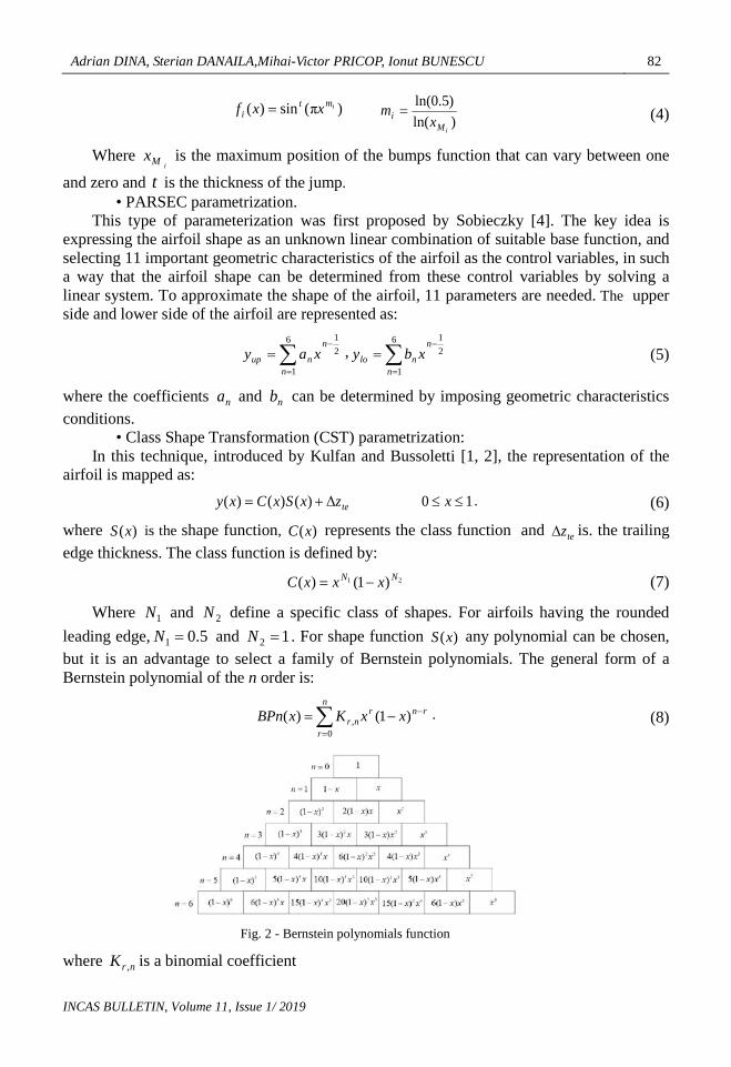
Where 1N and 2N define a specific class of shapes. For airfoils having the rounded leading edge, 5.01 =N and 12 =N . For shape function )(xS any polynomial can be chosen, but it is an advantage to select a family of Bernstein polynomials. The general form of a Bernstein polynomial of the n order is:
∑=
−−=n
r
rnrnr xxKxBPn
0, )1()( . (8)
Fig. 2 - Bernstein polynomials function
where nrK , is a binomial coefficient

83 Using genetic algorithms to optimize airfoils in incompressible regime
INCAS BULLETIN, Volume 11, Issue 1/ 2019
)!(!!
, rnrn
rn
K nr −=
= , (9)
and the shape function )(xS yields:
∑=
−−=n
r
rnrnri xxKAxS
0, )1()( . (10)
For flexibility, it is convenient to represent the upper and the lower side independently as:
10)1()1()(0
,21 ≤≤∆+−−= ∑
=
− xzxxKAuxxxy te
n
r
rnrnri
NNup (11)
10Δ)1()1()(0
,21 ≤≤+−−= ∑
=
− xzxxKAlxxxy te
n
r
rnrnri
NNlo . (12)
where the coefficients iAu and iAl can be selected as parameters in the optimization process. In our applications the order of Bernstein polynomials was n=6.
4. AERODYNAMIC MODEL In an optimization process, an objective function that must be minimized has to be defined. In our case the ratio of drag to the lift, /D LC C , was chosen. Then the fitness evaluation in the optimization algorithm requires the prediction of these aerodynamic characteristics of the each chromosome of successive populations.
Obliviously, a fast and relatively accurate aerodynamic model has to be implemented. Consequently, the linear potential model completed with the boundary layer correction was considered.
The panel method, which is the numerical method to solve the incompressible potential equation uses a superposition of particular solutions representing sources, doublets and vortices. The solution procedure for the panel technique consists of discretizing the surface of the airfoil into straight line segments or panels (Fig. 3).
There are many choices as how to formulate a panel method but the simplest and practical method was due to Hess and Smith [3]. We consider N+1 points equally distributed over the airfoil. The numbering system starts at the lower surface trailing edge and proceeds forward, around the leading surface and aft to the upper surface trailing edge [11].
1234
N + 1N
N - 1
node
panel Fig. 3 - Representation of an airfoil with straight line segments [6]
Sources and vortices with constant intensity are distributed along the panels. Imposing the slip condition on panel control points (usually the middle points) and the Kutta-Jukovski condition on the trailing edge a linear system of equations for the singularity intensities yields:

Adrian DINA, Sterian DANAILA,Mihai-Victor PRICOP, Ionut BUNESCU 84
INCAS BULLETIN, Volume 11, Issue 1/ 2019
11 1 1 1, 1 11
1 , 1
1 , 1
1,1 1, 1, 1, 1 1
i N N
i ii iN i N ii
N Ni NN N N NN
N N i N N N N N
A A A A bQ
A A A A bQ
A A A A bQA A A A bγ
+
+
+
+ + + + + +
… … … … … … … … …
= … … … … … …
… … …
, (13)
where the influence coefficients Aij and the right hand terms bi are given by the following equations:
( ) ( )11 1sin ln cos2 2
ijij i j i j ij
ij
rA
rθ θ θ θ β
π π+
= − + −
, i=1,N. j=1,N, (14)
( ) ( )1
1, 1
1 cos ln sin2
iji N i j i j ij
i
N
jj
rA
rθ θ θ θ β
π =
++
= − − − ∑ , i=1,N, (15)
( ) ( ), 1111 sin sin
2N j j j N j NjA θ θ β θ θ βπ+
= − + − −
( ) ( )11 1 1
1
cos ln cos lnj Njj N j
j Nj
r rr r
θ θ θ θ+ + − − − −
, (16)
( ) ( )1 1 11,
11 1
1
1 sin ln sin ln2
Nj Nj
N N j N jj Njj
r rA
r rθ θ θ θ
π+
=
++ +
= − + − +
∑
( ) ( )1 1cos cosj j N j Njθ θ β θ θ β+ − + − ,
(17)
( )sin sini ib V θ α∞= − , ( ) ( )1 1 Ncos cosNb V Vθ α θ α+ ∞ ∞= − − − − . (18)
where the geometrical parameters are sketched in Fig. 4, and α is the angle of attack. Once the system is solved, the induced velocities and the pressure coefficient on control
points can be calculated. Then, the lift coefficient results by summing the pressure forces on all panels.
Fig. 4 - Geometrical parameters

85 Using genetic algorithms to optimize airfoils in incompressible regime
INCAS BULLETIN, Volume 11, Issue 1/ 2019
Thwaites integral method [12] is used to calculate the laminar boundary layer parameters starting from the stagnation point to the transition onset, according to the following relation:
2 56
0
0.45 x
ee x
U dxU
νθ=
= ∫
(19)
where ( )eU x is the velocity distribution along the airfoil surface determined by the panel method and ν is the kinematic viscosity. After θ is found, the following correlations are used to compute the shape factor H:
22.61 3.75 5.24 0 0.1;H λ λ λ= − + ≤ ≤
(20)
0.01472.472 0.1 0,0.107
H λλ
= + − ≤ ≤+
(21)
where:
dxdue
νθ
=λ2
, (22)
The shear stress and the friction coefficient are estimated by the following empirical relation:
0.62( 0.09)ew
Uµτ λ
θ= + ,
212
wf
e
CU
τ
ρ= ,
(23)
The empirical criteria reported by Michel [14] are used in the present work to describe the location of the transition due to the growth of Tollmien-Schlichting assumed to occur when the local Reynolds number based upon the momentum thickness exceeds a critical value determined by the equation,
4.0tr,r, Re9.2Re xt =θ ,
ν=
xUexRe ,
νθ
=θeURe (24)
where θRe and xRe are the local Reynolds numbers based on momentum thickness and the distance from the airfoil leading edge, respectively. In the turbulent region of the boundary layer, the integral Head [13] method is employed to predict the turbulent flow parameters. Head suggested a new shape parameter 1H , given by
θδ−δ
≡*
1H
(25)
and the evolution of 1H along the boundary layer is given by the equation:
6169.011 )3(0306.0)(1 −−=θ HHU
dxd
U (26)
Equation (26) and Von Karman Momentum global equation:
dxdU
UH
dxdC e
e
f θθ )2(2
++=
(27)
are solved by moving from the transition location to the trailing edge. For closure Head proposed:

Adrian DINA, Sterian DANAILA,Mihai-Victor PRICOP, Ionut BUNESCU 86
INCAS BULLETIN, Volume 11, Issue 1/ 2019
6.1)1.1(8234.03.3 287.11 ≤−+= − HHH
(28)
6.1)6788.0(5501.13.3 064.31 ≥−+= − HHH
(29)
Friction coefficient in Head method is calculated by Ludwig-Tillman formula: 268.0678.0 Re)10(246.0 −
θ−= H
fC
(30)
The previously presented methods (the panel method and the boundary layer correction method) were applied to develop a Matlab program to estimate the fitness of the chromosomes in genetic algorithm. This variant of the resulting optimization program will be denoted in the following as Optaero.
A second code was developed in order to? check the results and to quantify the influence of the accuracy in evaluation of the aerodynamic characteristics. This code denoted Optx, uses the XFOIL program to calculate the lift and drag of a given airfoil. XFOIL is a free software aerodynamic code released under the General Public License. The flow solution in XFOIL is based on linear vortex panel method, coupled with a boundary layer model.
5. NUMERICAL RESULTS AND CONCLUSIONS In the following we will present some numerical solutions prescribed by the two codes: OptAero and Optx. Both codes are based on the Global Optimization Toolkit of Matlab, but with different flow solvers, as previously mentioned. Assuming a CST parametrization of the airfoil shape, equations (11) and (12), the design parameters were the coefficients iAu and
iAl , i=1,6. The airfoil was presumed having the rounded leading edge, the flow incompressible and a small angle of attack (0-0.5 deg). The data required by the GA were: the population number of 40, the recombination factor of 0.4, the mutation factor of 0.5, and the convergence criterion of 310− . Four cases are presented, corresponding to four values of the Reynolds number VcU /Re ∞= : 105, 5 105, 106, 5 106.
The results of the OptAero program are presented in Table 1. In this table, lC is the lift coefficient, dC is the drag coefficient, tezΔ is the trailing edge thickness, p represents the position of a maximum curvature, m is the maximum curvatures, b is the position of a maximum thickness and t - the maximum thickness for the optimum airfoil.
Table 1 - Result from OptAero
OPTAERO AIRFOIL 1
0=α 510Re =
29.0=lC
021.0=dC
406.015.003.0
===
ptm
003.0232.0
=∆=
tezb
AIRFOIL 2
0α = 5105Re ⋅=
35.0=lC
010.0=dC
406.016.0031.0
===
ptm
003.0232.0
=∆=
tezb

87 Using genetic algorithms to optimize airfoils in incompressible regime
INCAS BULLETIN, Volume 11, Issue 1/ 2019
AIRFOIL 3 0α =
610Re =
34.0=lC 0058.0=dC
376.0147.0029.0
===
ptm
003.0375.0
=∆=
tezb
AIRFOIL 4
0=α 6105Re ⋅=
36.0=lC 0058.0=dC
345.0147.0032.0
===
ptm
003.0345.0
=∆=
tezb
In Fig. 5 and 6 the airfoil polars are represented. We note the extremely large values of
the drag coefficient for low Reynolds number flows. These values are prescribed by the in-house aerodynamic code.
Fig. 5 - Cl vs Alpha (code Optaero)
Fig. 6 - Cl vs Cd (code Optaero)
The results of the second program, in which the aerodynamic performances are predicted by XFOIL, are presented in Table 2. In Fig. 7 and 8 the polar of the optimum shape are traced.
Table 2 - Result from OptX OPTX
AIRFOIL 1 0=α
510Re =
4.0=lC
016.0=dC
206.0130.0026.0
===
ptm
032.0287.0
=∆=
tezb
AIRFOIL 2
0=α 5105Re ⋅=
395.0=lC
0073.0=dC 376.0146.00322.0
===
ptm
032.0345.0
=∆=
tezb
AIRFOIL 3
0=α 610Re =
4.0=lC
0075.0=dC 469.0
150.00321.0
===
ptm
032.0316.0
=∆=
tezb
AIRFOIL 4
0=α 6105Re ⋅=
4.0=lC
0047.0=dC
468.0139.0030.0
===
ptm
032.0406.0=∆
=
tezb

Adrian DINA, Sterian DANAILA,Mihai-Victor PRICOP, Ionut BUNESCU 88
INCAS BULLETIN, Volume 11, Issue 1/ 2019
Again we made the polars for each airfoil for the same case as before o)6...2(−∈α and 610Re = :
Fig. 7 - Cl vs Alpha (code OptX)
Fig. 8 - Cl vs Cd (OptX)
Fig. 9 - Airfoils geometry comparison between OptAero and OptX programs
Fig. 9 presents a comparison of results of programs.
6. CFD RESULTS To verify, the obtained results for Airfoils-4 case from both programs were analyzed using Ansys-Fluent. Analyzing the two profiles in ANSYS, for the case of a viscous flow in incompressible regime at zero incidence using the k-omega SST method, we obtained the values shown in Table 3.4.
Table 3 - Comparison with the Ansys-Fluent
Airfoil4 - OptAero Airfoil4 – OptX - ANSYS Fluent Optimizer - ANSYS Fluent Optimizer
lC 0.3469 0.3685 lC 0.38002 0.4018
dC 0.00579 0.00585 dC 0.00573 0.00477
mC -0.05062 -0.064 mC -0.06789 -0.078

89 Using genetic algorithms to optimize airfoils in incompressible regime
INCAS BULLETIN, Volume 11, Issue 1/ 2019
Fig. 10 - Pressure Coefficient OptAero
Fig. 11 - Pressure Coefficient OptX
7. CONCLUSIONS Following the optimizations obtained, the following conclusions can be drawn:
• Designing an airfoil is a major activity in the aerodynamic design of an aircraft. • Five methods for parameterization of the shape of an aerodynamic profile were
selected. A method called Class Forms (CST) was chosen to generate the curve, due to the simplicity of the implementation and to the very small number of design parameters.
• Using a simplified aerodynamic model can accelerate the optimization process, but the results will not be the most satisfactory. Using a more advanced aerodynamic coefficient computation model, it can delay the process with an order of magnitude, but the results are of better quality.
• By optimizing the airfoils at different Re numbers, we found that airfoils with an increase in the number of Re profiles tend to become laminar, the maximum thickness and curvature moving to the trailing edge of the profile.
• The genetic algorithm uses constraints that can be imposed both in the geometric definition of the airfoil and in the aerodynamics characteristic.

Adrian DINA, Sterian DANAILA,Mihai-Victor PRICOP, Ionut BUNESCU 90
INCAS BULLETIN, Volume 11, Issue 1/ 2019
ACKNOWLEDGEMENT This paper is a part of the work in the bachelor’s thesis “Using genetic algorithm for airfoil optimization in incompressible regime”, by Adrian DINA, awarded with the “Nicolae TIPEI” prize during The International Conference of Aerospace Sciences “AEROSPATIAL 2018”, 25 - 26 October 2018, Bucharest, Romania, organized by the INCAS – National Institute for Aerospace Research “Elie Carafoli”. I would like to express my deep gratitude to Professor PhD. Eng. Sterian DANAILA and Eng. Mihai-Victor PRICOP, my research supervisors, for their patient guidance and useful critiques of this research work. I would also thanks to Professor Sever TIPEI the son of Nicolae TIPEI and to the INCAS institute, led by PhD. Eng. Catalin NAE, for their support and encouragement for young researchers.
REFERENCES [1] B. Kulfan, J. Bussoletti, “Fundamental” Parameteric Geometry Representations for Aircraft Component
Shapes, in: 11th AIAA/ISSMO multidisciplinary analysis and optimization conference, p. 6948, 2006. [2] B. M. Kulfan, Universal parametric geometry representation method, Journal of Aircraft, 45.1: 142-158,
2008. [3] S. Dănăilă, C. Berbente, Metode numerice în dinamica fluidelor, Bucureşti, Editura Academiei Romane,
2003. [4] H. Sobieczky, Parametric airfoils and wings, in: Recent development of aerodynamic design methodologies,
Vieweg+ Teubner Verlag, p. 71-87, 1999. [5] H. Sobieczky, Aerodynamic design and optimization tools accelerated by parametric geometry preprocessing,
in: European congress on computational methods in applied sciences and engineering, ECCOMAS, 2000. [6] H.-Y. Wu, et al., Comparisons of Three Geometric Representations of Airfoils for Aerodynamic Optimization,
in: 16th AIAA computational fluid dynamics conference, p. 4095, 2003. [7] D. A. Masters, et al., Review of aerofoil parameterisation methods for aerodynamic shape optimization, in:
53rd AIAA Aerospace Sciences Meeting, p. 0761, 2015. [8] J. H. Holland, Genetic algorithms and the optimal allocation of trials, SIAM Journal on Computing, 2.2: 88-
105, 1973. [9] J. H. Holland, Adaptation in natural and artificial systems: an introductory analysis with applications to
biology, control, and artificial intelligence, MIT press, 1992. [10] L. D. Chambers, The practical handbook of genetic algorithms: applications, Chapman and Hall/CRC, 2000. [11] J. Katz and A. Plotkin, Low-Speed Aerodynamics: From Wing Theory to Panel Methods, McGraw-Hill
Series in Aeronautical and Aerospace Engineering, McGraw-Hill, Inc., ISBN 0-07-100876-4, 1991. [12] B.Thwaites, Approximate calculation of the laminar boundary layer, The Aeronautical Quarterly, 1.3: 245-
280, 1949. [13] H. Schlichting and K. Gersten, Boundary-Layer Theory, Book, Publisher: Springer Berlin Heidelberg (Nov
1999), 8th Revised and Enlarged Edition, 2008. [14] R. Michel, Etude de la transition sur les profile d’ aile; Edtablishment d’un critere de determination de point
de transition et calcul de la trainee de profile incompressible, ONERA Report 1/1578A, 1951.


![Blended Wing’ CFD Analysis: Aerodynamic Coefficients. · airfoils at low Reynolds numbers, such as the XFLR5 [5, 7]. Nevertheless, the values obtained through this software are](https://img.dokumen.tips/doc/110x75/5e68547c68b2a32bb7246be4/blended-winga-cfd-analysis-aerodynamic-airfoils-at-low-reynolds-numbers-such.jpg)


![Aerodynamic Optimization Trade Study of a Box-Wing ...oddjob.utias.utoronto.ca/~dwz/Miscellaneous/gagnonzingg...only supercritical airfoils are selected [18]. Specifically, for the](https://img.dokumen.tips/doc/110x75/5ac15cd07f8b9a357e8c96b3/aerodynamic-optimization-trade-study-of-a-box-wing-dwzmiscellaneousgagnonzinggonly.jpg)