Embed Size (px)
Citation preview

User’sManual
IM XL100C-E
XL100Portable Data StationCommunication Function
IM XL100C-E1st Edition: October 2005 (MC)
1IM XL100C-E
IntroductionThank you for purchasing our XL100 Portable Data Station.
This Communication Function Manual provides information necessary for usingcommunication functions and creating communication programs. To ensure correct use,please read this manual thoroughly before beginning operation.
In addition to this manual, the User’s Manual (contained in the CD-ROM as with thismanual) and Quick Setup Manual are available separately.The User’s Manual provides detailed information regarding all of the functions and
operations of the XL100 excluding the communication functions. The Quick SetupManual briefly explains the basic operations such as measurement operation and setup.Use them together with this manual.
After reading this manual, keep it in an easily accessible place for later reference. Thismanual will come in handy when you are unsure of how to operate the product.
Notes• The contents of this manual are subject to change without prior notice.• Figures and illustrations representing display views in this manual may differ from
actual views.• Every effort has been made to ensure accuracy in the preparation of this manual.
However, should any doubts arise or errors come to your attention, please contact the
vendor from whom you purchased the product.• The contents of this manual may not be transcribed or reproduced, in part or in their
entirety, without prior permission.
Trademark AcknowledgementsThe company and product names referred to in this document are either trademarks or
registered trademarks of their respective holders.
Revision InformationFirst Edition: October, 2005
1st Edition: October 2005 (MC)
All Rights Reserved, Copyright © 2005, Yokogawa M&C Corporation

2 IM XL100C-E
Safety Precautions
When operating the instrument, be sure to observe the cautionary notes given below toensure correct and safe use of the instrument. If you use the instrument in any way other
than as instructed in this manual, the instrument’s protective measures may be impaired.Yokogawa Meters & Instruments Corporation is by no means liable for any damageresulting from use of the instrument in contradiction to these cautionary notes.
The following safety symbols are used on the instrument and in this manual.
Danger! Handle with Care. This symbol indicates that the operator must refer to
an explanation in the User’s Manual or this manual in order to avoid risk of injuryor death of personnel or damage to the instrument.
This symbol indicates DC voltage/current.
This symbol indicates AC voltage/current.
This symbol indicates ON (power).
This symbol indicates OFF (power).
WARNING
Indicates a hazard that may result in the loss of life or serious injury of the userunless the described instruction is abided by.
CAUTION
Indicates a hazard that may result in an injury to the user and/or physical damageto the product or other equipment unless the described instruction is abided by.
NoteIndicates information that should be noted in order to familiarize yourself with theinstrument’s operating procedures and/or functions or gives supplementary information.
3IM XL100C-E
Description of Displays and Exemption fromResponsibilityDescription of Displays
• Some of the representations of product displays shown in this manual may beexaggerated, simplified, or partially omitted for reasons of convenience whenexplaining them.
• Figures and illustrations representing the controller’s displays may differ from theactual displays in regard to the positions and/or indicated characters (upper-case orlower-case, for example), to the extent that they do not impair correct understanding
of the functions and the proper operation and monitoring of the system.
Exemption from Responsibility• Yokogawa Meters & Instruments does not make any warranties regarding the product
except those mentioned in the WARRANTY that is provided separately.• Yokogawa Meters & Instruments assumes no liability to any party for any loss or
damage, direct or indirect, caused by the use of the product, or any unpredictabledefect of the product.
• Be sure to use spare parts approved by Yokogawa Meters & Instruments when
replacing parts or consumables.• Modification of the product is strictly prohibited.• Reverse engineering such as the disassembly or decompilation of software is strictly
prohibited.• No portion of the product supplied by Yokogawa Meters & Instruments may be
transferred, exchanged, leased or sublet for use by any third party without the prior
permission of Yokogawa Meters & Instruments.
4 IM XL100C-E
Contents
Safety Precautions ......................................................................................................................... 2Description of Displays and Exemption from Responsibility .......................................................... 3
Chapter 1 Overview of the Communication Functions1.1 Relationship between the Communication Function and the Ethernet and Serial
Interfaces ......................................................................................................................... 1-11.2 Explanation of Functions .................................................................................................. 1-2
Chapter 2 Ethernet Interface2.1 Ethernet Interface Specifications ..................................................................................... 2-12.2 Connecting of the Ethernet Interface ............................................................................... 2-22.3 Configuring of the Ethernet Interface ............................................................................... 2-3
2.4 Checking the Connection Status of the Ethernet Interface .............................................. 2-72.5 Setting the FTP Client (Setting the Auto Transfer of Measurement and Alarm Data
Files) ................................................................................................................................ 2-8
2.6 FTP Test ........................................................................................................................ 2-112.7 Setting the Login and Timeout Functions of Ethernet Communications ........................ 2-132.8 Showing the Error, Communication, and FTP Log Displays .......................................... 2-15
2.9 Setting the Web Server Function ................................................................................... 2-182.10 Showing and Using the Monitor or Operator Page ........................................................ 2-212.11 Setting the E-mail Transmission Function ..................................................................... 2-23
2.12 E-mail Transmission Test .............................................................................................. 2-282.13 Starting/Stopping E-mail Transmissions ........................................................................ 2-30
Chapter 3 Serial Interface3.1 RS-232 Interface Specifications and Setup Procedure .................................................... 3-13.2 RS-485 Interface Specifications and Setup Procedure .................................................... 3-5
3.3 USB Communication Specifications and Setup Procedure ............................................. 3-8
Chapter 4 Modbus Protocol4.1 Modbus Protocol Specifications and Function Codes ...................................................... 4-14.2 Register Assignments (for Modbus Slave) ....................................................................... 4-2
4.3 Modbus Error Response (for Modbus Slave) ................................................................... 4-34.4 Setting the Modbus Master Function ............................................................................... 4-44.5 Data Dropout Handling of the Modbus Master ................................................................. 4-7
Chapter 5 Standard Protocol5.1 Command Syntax ............................................................................................................ 5-15.2 Response Syntax ............................................................................................................. 5-35.3 A List of Commands ....................................................................................................... 5-19
5.4 Input Range Parameters ................................................................................................ 5-235.5 Setting Commands (Setting) .......................................................................................... 5-255.6 Setting Commands (Control) ......................................................................................... 5-30
5.7 Basic Setting Commands ............................................................................................... 5-315.8 Output Commands (Control) .......................................................................................... 5-385.9 Output Commands (Setting/Measurement/Data Output) ............................................... 5-39
5.10 Output Commands (RS-485 and USB Dedicated Commands) ..................................... 5-415.11 Maintenance/Test Commands (Available when using the maintenance/test server
function via Ethernet communications) .......................................................................... 5-42
5IM XL100C-E
11
2
3
4
5
6
7
AppApp
IndexIndex
Chapter 6 Status6.1 Status Information andFilter ............................................................................................. 6-16.2 Bit Structure of the Status Information ............................................................................. 6-2
Chapter 7 Error Messages7.1 Error Messages Related to Settings ................................................................................ 7-1
7.2 Error Messages Related to Operation ............................................................................. 7-37.3 Communication Error Messages ...................................................................................... 7-8
AppendixAppendix 1 ASCII Character Codes .......................................................................................App-1
Appendix 2 Login Process......................................................................................................App-2Appendix 3 Data Output Flow ................................................................................................App-4
Index
Contents
1-1IM XL100C-E
11
2
3
4
5
6
7
App
Index
Overview
of th
e Co
mm
un
ication
Fu
nctio
ns
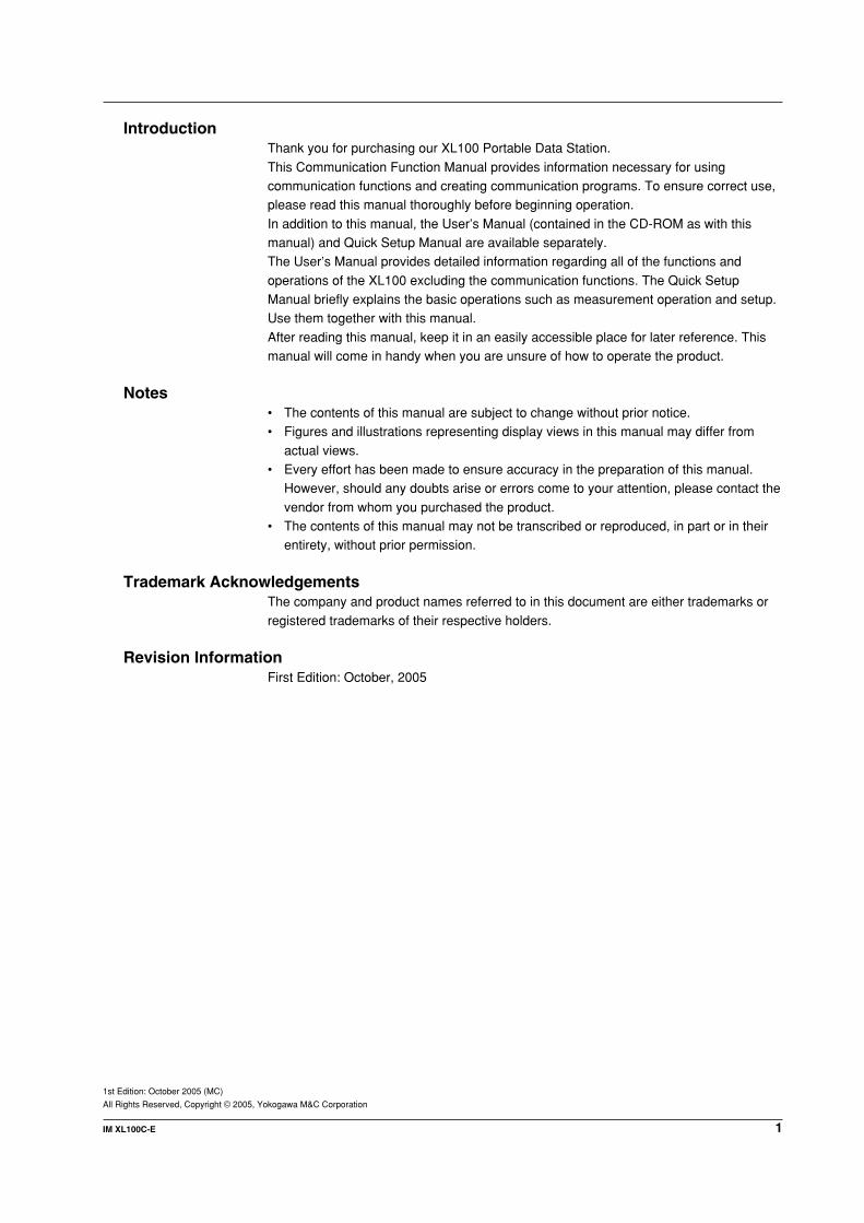
1.1 Relationship between the CommunicationFunction and the Ethernet and Serial Interfaces
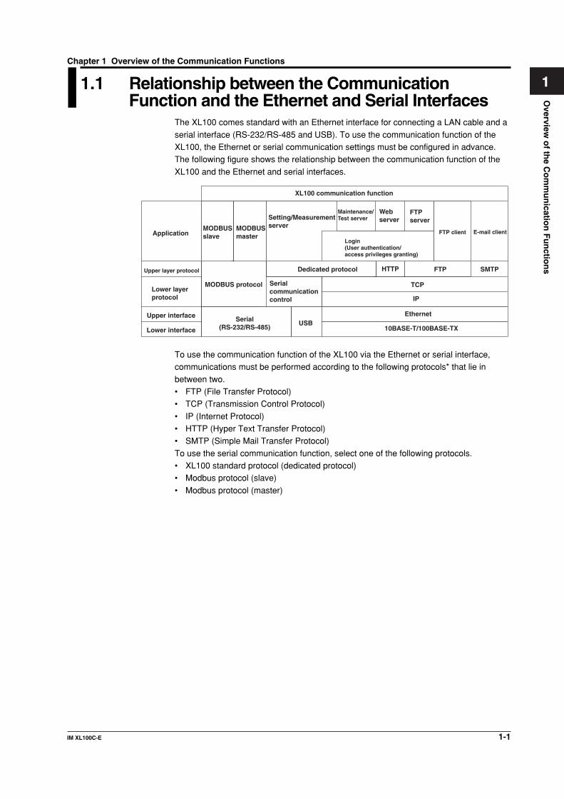
The XL100 comes standard with an Ethernet interface for connecting a LAN cable and a
serial interface (RS-232/RS-485 and USB). To use the communication function of theXL100, the Ethernet or serial communication settings must be configured in advance.The following figure shows the relationship between the communication function of the
XL100 and the Ethernet and serial interfaces.
Application
10BASE-T/100BASE-TX
IP
Serial communication control
MODBUS slave
FTP server
Maintenance/Test serverSetting/Measurement
server
XL100 communication function
MODBUS master
Serial(RS-232/RS-485)
Lower layer protocol
Upper layer protocol
Upper interface
Lower interface
Web server
FTP client E-mail client
USB
MODBUS protocol
Dedicated protocol HTTP FTP SMTP
TCP
Ethernet
Login(User authentication/access privileges granting)
To use the communication function of the XL100 via the Ethernet or serial interface,communications must be performed according to the following protocols* that lie in
between two.• FTP (File Transfer Protocol)• TCP (Transmission Control Protocol)
• IP (Internet Protocol)• HTTP (Hyper Text Transfer Protocol)• SMTP (Simple Mail Transfer Protocol)
To use the serial communication function, select one of the following protocols.• XL100 standard protocol (dedicated protocol)• Modbus protocol (slave)
• Modbus protocol (master)
Chapter 1 Overview of the Communication Functions

1-2 IM XL100C-E
1.2 Explanation of Functions
This section gives an overview of the communication function that can be used to controlthe XL100.
Modbus CommunicationModbus Slave• The Modbus protocol can be used to read the measured/calculated data written to the
input register of the XL100 from a PC or write/read communication input data from thehold register of the XL100.
• For details on the Modbus function codes that the XL100 supports, see section 4.1.• This function can be used only when communicating via the serial interface.• For a description on the settings required to use this function, see sections 4.2 and
4.3.
Modbus Master• Loads the measured data and other types of data of other instruments using the
Modbus protocol as communication channel input. The loaded data can be scaledand displayed with a unit that you assign. The data can also be used as a calculation
channel.• Function for writing data to other instruments is not supported.• For details on the Modbus function codes that the XL100 supports, see section 4.1.
• This function can be used only when communicating via the serial interface.• For a description on the settings required in using this function, see section 4.4.
Setting/Measurement Server• This function can be used to set almost all of the settings that can be configured using
the front panel keys. This function cannot be used to (1) turn the power switch ON/OFF, (2) set the user name/password for communications, (3) set the user name/
password for key login, and (4) set the destination of the FTP client function.• The following types of data can be output.
• Measured/calculated data.
• Data in the internal memory or files in the external storage medium.• Setup data.• Log data of operation errors and communications.
• The commands that can be used through this function are setting commands andoutput commands.
• This function can be used when communicating via the Ethernet or the serial
interface.
Maintenance/Test Server• This function can be used to output connection information, network information, and
other information regarding Ethernet communications.• The commands that can be used through this function are maintenance/test
commands.• This function can be used only when communicating via the Ethernet interface.

1-3IM XL100C-E
11
2
3
4
5
6
7
App
Index
Overview
of th
e Co
mm
un
ication
Fu
nctio
ns
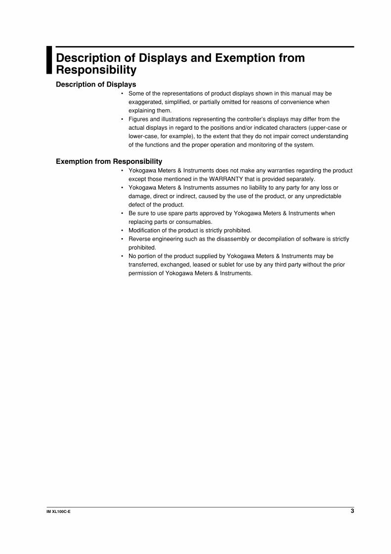
FTP Server• You can use a PC to access the XL100 via FTP. You can perform operations such as
retrieving directory and file lists from the internal memory or the external storagemedium of the XL100 and transferring and deleting files.
• This function can be used only when communicating via the Ethernet interface.
PC
Ethernet
Hub
Hub
Load measured data
PC
Load measured data
FTP server
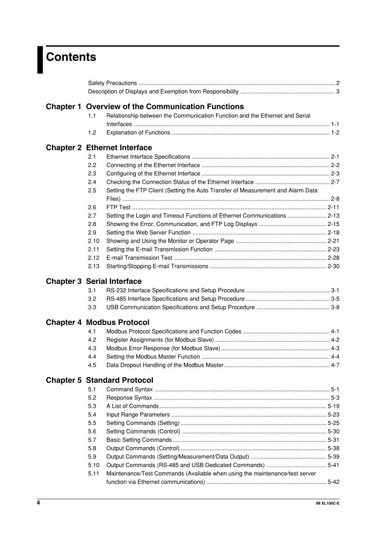
FTP Client• Automatic File Transfer
• The display data file and log data file that are created in the internal memory of the
XL100 can be automatically transferred to a remote FTP server. The result of thetransfer is recorded in the FTP log. The FTP log can be shown on the XL100’sdisplay or output to a PC using commands.
Ethernet
Primary FTP server
Hub
Hub
Automatically save measured data
Secondary FTP server
FTP client
You can specify two destination FTP servers, primary and secondary. If the primary
server is down, the file is transferred to the secondary server.• This function can be used only when communicating via the Ethernet interface.
• FTP Test• The file transfer can be checked by transferring a test file from the XL100 to a
remote FTP server.
• The result of the FTP test can be confirmed on the FTP log display.• This function can be used only when communicating via the Ethernet interface.
1.2 Explanation of Functions

1-4 IM XL100C-E
Login• This function can be used only when communicating via the Ethernet interface and
when using the setting/measurement server, maintenance/test server, and the FTPserver functions.
• User AuthenticationThis function allows only registered users to access the XL100 in order to preventinvalid access from the network.• Up to seven names can be registered. One of the names is fixed to administrator
privilege. For the other six names, you specify the access privilege when youregister the name.
• There are limitations on the number of simultaneous connections and the number
of simultaneous users accessing the XL100 from PCs (see section 2.1).
• Granting Access PrivilegesThis function grants access privilege (user level) to operate the XL100 for theregistered users. For example, this prevents user B (user level) from changing themeasurement conditions that were set by user A (administrator level).
• There are two user levels on the XL100, user and administrator.• Administrator
An administrator has privileges to use all setting/measurement server functions,
maintenance/test server functions, and FTP server functions.• User
A user has limited privileges to use the setting/measurement server functions,
maintenance/test server functions, and FTP server functions.• Limitations on the use of the setting/measurement server
A user cannot change settings that would change the XL100 operation. A
user can output measured data and setting data.• Limitations on the use of the maintenance/test server
A user cannot disconnect a connection between another PC and the XL100.
A user can disconnect the connection between the PC that the user is usingand the XL100.
• Limitations on the use of the FTP server
You cannot save files to the external storage medium of the XL100 or deletefiles on it. You can load files.
• Communication TimeoutThis function drops the connection with the PC if there is no data transfer for a giventime at the application level. For example, this function prevents a PC from beingconnected to the XL100 indefinitely which would prohibit other users from making new
connections for data transfer.
Web Server• This function can be used only when communicating via the Ethernet interface.• The XL100 display can be shown on a Web browser (for Web browsers that have
been tested for compatibility, see section 2.10).
• The following two pages are available.• Monitor page: Monitoring screen (switching is possible among measurement
data displays, alarm summary display, and log displays)
• Operator page: This page allows you to switch the XL100 display. You can alsoswitch to Setting mode or File Operation mode to control theXL100 in the respective mode.
You can use access control (user name and password) to limit the access to eachpage.
1.2 Explanation of Functions

1-5IM XL100C-E
11
2
3
4
5
6
7
App
Index
Overview
of th
e Co
mm
un
ication
Fu
nctio
ns
• The display section of the XL100 can be updated periodically (select from 2, 5, 10, or30 s).
• The following information can be displayed.• Measured data• Alarm summary
• Logs (error log, communication command log, key login/logout log, FTP client log,e-mail log, and Web operation log)
E-mail TransmissionThis function can be used only when communicating via the Ethernet interface.• Transmitting E-mail Messages
• E-mail can be automatically transmitted at the times indicated below. You canspecify two groups of destinations and specify the destination for each item. Inaddition, you can set a header string for each item.
• When an alarm is activated/releasedNotifies alarm information.
• When the XL100 recovers from a power failure
Notifies the time of the power failure and the time of recovery.• When an error related to the external storage medium and FTP client occurs
Notifies the error code and message when an error is detected on the external
storage medium or when the data cannot be stored due to insufficient freespace on the external storage medium. In addition, notifies the error code andmessage when data transfer fails using the FTP client function.
• At the specified timeTransmits an e-mail message when the specified time is reached. This can beused to confirm that the e-mail transmission function including the network is
working properly. You can specify the reference time and the e-mail transmissioninterval for each destination.
• E-mail Transmission Test• You can send a test message from the XL100 to the destination to check e-mail
transmissions.• You can confirm the result of the e-mail transmission test on the e-mail log screen.
Other Functions• SNTP (Simple Network Time Protocol) Connection
You can synchronize the standard clock by connecting to an SNTP server when usingthe Ethernet interface.
• Checking the Connection Status of the Ethernet InterfaceYou can check the connection status of the Ethernet interface with the LAN port LEDon the side panel of the XL100 and on the display of the XL100.
• Keepalive (Extension Function of TCP)This function drops the connection if there is no response to the test packet that issent periodically at the TCP level.
• Displaying the Error, Communication, FTP, Web Operation, and E-mail LogsYou can display the following operation logs on the log display.
• Error log display: Log of operation errors.• Communication command display: Log of communication input/output.• FTP client log display: Log of file transfers carried out using the FTP client function.
• Web operation log display: Log of operations using the Web server function.• E-mail log display: Log of e-mail transmissions.
1.2 Explanation of Functions

2-1IM XL100C-E
Eth
ernet In
terface
1
2
3
4
5
6
7
App
Index
2.1 Ethernet Interface Specifications
Basic Specifications
Item Specifications
Number of ports 1
Electrical and mechanical specifications Conforms to IEEE 802.3.
Transmission medium type Ethernet (100BASE-TX/10BASE-T)
Data rate 100 Mbps maximum
Protocol TCP/IP
Supported services FTP server, FTP client, SMTP client (mailtransmission), Web server, DHCP, DNS, and SNTP
Connector type RJ-45
Maximum Number of Simultaneous Connections/Number of Simultaneous UsersThe following table shows the maximum number of simultaneous connections, the
number of simultaneous users, and the port number for each function.
Function Maximum Number Number of Simultaneous Users Port Number*1
of Connections Administrator User
Setting/Measurement server 3 1 2*2 34339
Maintenance/Test server 1 1 1*2 34340
FTP server 2 2 2*2 21
*1 The port numbers are fixed.*2 There are user limitations. For details, see “Granting Access Privileges” under “Login” in section 1.2.
Chapter 2 Ethernet Interface

2-2 IM XL100C-E
2.2 Connecting of the Ethernet Interface
When Connecting Only the XL100 and the PCConnect the LAN ports of the XL100 and the PC using a 10BASE-T or 100BASE-TX
LAN cable.
LOGIC/PULSE
ALARMRS232
LAN port
LAN cable
If you are connecting the XL100 and the PC directly in a one-to-one configuration withoutusing a hub, use a cross LAN cable.
When Connecting to an Existing NetworkWhen connecting the XL100 or the PC to an existing network, communicationparameters such as the data rate and connector type must be matched. For details,
consult your system or network administrator.
Note• Depending on the reliability of the network or the volume of network traffic, all the
transferred data may not be retrieved by the PC.
• Communication performance deteriorates if multiple PCs access a XL100simultaneously.
• If the interface is not set to LAN, do not connect the LAN cable.

2-3IM XL100C-E
Eth
ernet In
terface
1
2
3
4
5
6
7
App
Index
2.3 Configuring of the Ethernet Interface
The following configurations must be made to use the Ethernet communication functionsof the XL100.
Selecting the Communication InterfaceCommunication can only be performed on a single interface at any given time. You must
select the communication interface by carrying out the steps below. The default setting isLAN (Ethernet).
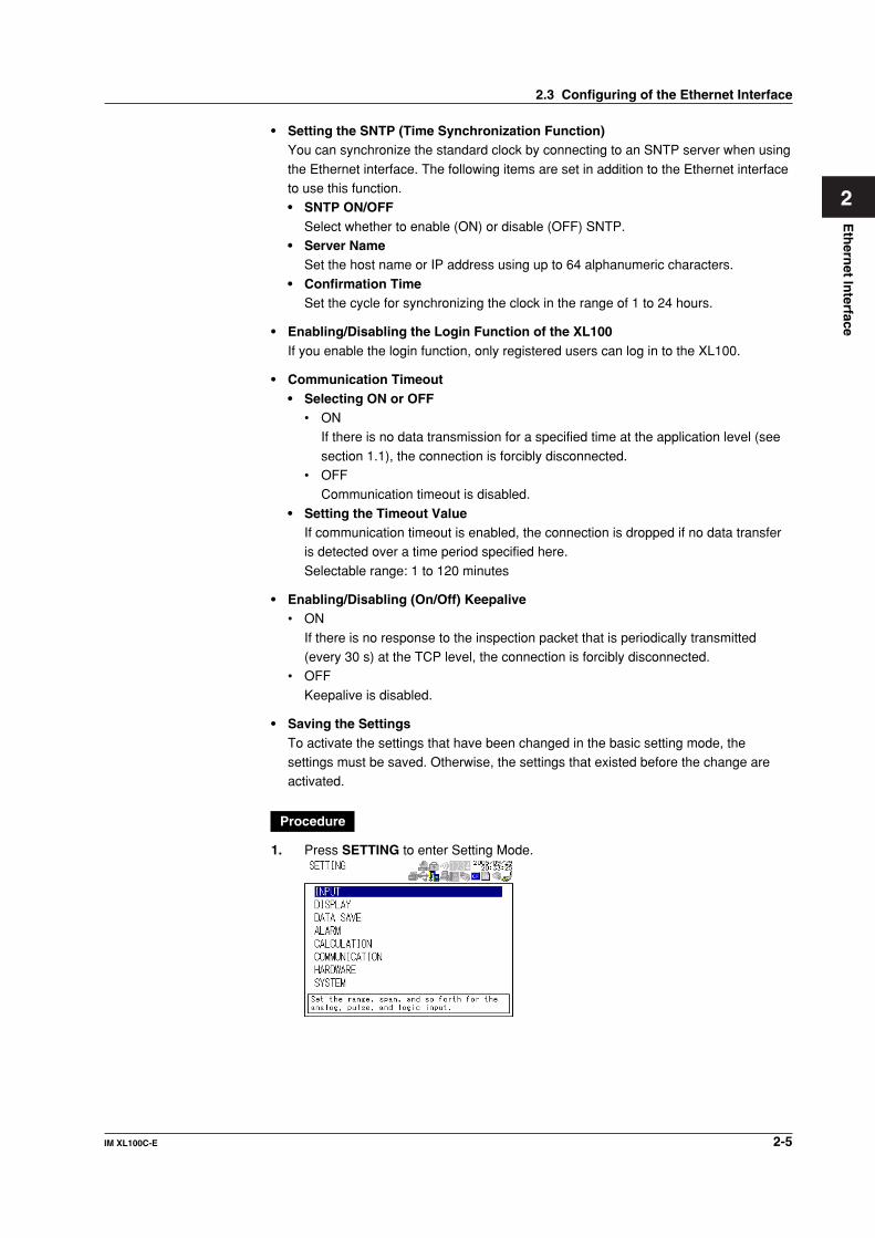
Procedure
1. Press SETTING to enter Setting Mode.
2. Use the arrow keys to select COMMUNICATION, and press SELECT.
→
3. With INTERFACE selected, press SELECT.An interface selection list is displayed.
4. Use the arrow keys to select a communication interface, and press SELECT.
5. Press SET.
Setting the Ethernet Parameters• Setting the Time Zone
Set the time difference from Greenwich Mean Time.
• Setting the DHCP, IP Address, Subnet Mask, Default Gateway, and DNSConsult your system or network administrator when setting parameters such as the IP
address, subnet mask, default gateway, and DNS (domain name system).• DHCP (Dynamic Host Configuration Protocol)
• The IP address, subnet mask, default gateway, and DNS can be automatically
set by using DHCP.• To use DHCP, the network must have a DHCP server.• Consult your network administrator to see if DHCP can be used.
• If you use DHCP, a different IP address may be assigned each time the XL100is powered up. You must pay attention when using the FTP server function ofthe XL100.
2-4 IM XL100C-E
• IP Address• Set the IP address to assign to the XL100. The default setting is 0.0.0.0.
• The IP address is used to distinguish between the various devices connected tothe Internet when communicating using the TCP/IP protocol. The address is a32-bit value expressed using four octets (each 0 to 255), each separated by a
period as in [192.168.111.24].• Subnet Mask
• Specify the mask that is used to determine the network address from the IP
address. The default setting is 0.0.0.0.• Set the value according to the system or network to which the XL100 belongs. In
some cases, this setting may not be necessary.
• Default Gateway• Set the IP address of the gateway (router, etc.) used to communicate with other
networks. The default setting is 0.0.0.0.
• Set the value according to the system or network to which the XL100 belongs. Insome cases, this setting may not be necessary.
• DNS (Domain Name System)You must set the DNS if you are using a host name to specify the destinationserver of the file transfer on an FTP client or the server of the e-mail recipient.* DNS is a system used to associate names used on the Internet called host
names and domain names to IP addresses. The host name/domain name canbe used instead of the IP address when accessing the network. The DNS servermanages the database that contains the host name/domain name and IP
address correlation.• DNS Server
• Set the IP address of the DNS server. The default setting is 0.0.0.0.
• You can specify up to two DNS server IP addresses, primary and secondary.If the primary DNS server is down, the secondary DNS server is automaticallylooked up for the mapping of the host name/domain name and IP address.
• Host NameSet the XL100’s host name using up to 64 characters.
• Domain Name• Set the network domain name that the XL100 belongs to using up to 64
characters.• When the destination server of the file transfer or the server of the e-mail
recipient is looked up using the DNS server, this domain name is appendedto the host name as a possible domain name if it is omitted. The recipientname (server name) is set to the name specified by FTP Server Name or
SMTP Server Name.• Domain Suffix
When the IP address corresponding to the server name with the domain name
of the previous section is not found, the system may be set up to search using adifferent domain name. In such cases, set the domain name to be searchedfollowing the “domain name” of the previous section as a domain suffix.
• Set the domain suffix using up to 64 characters.• You can specify up to two domain suffixes, primary and secondary.
2.3 Configuring of the Ethernet Interface
2-5IM XL100C-E
Eth
ernet In
terface
1
2
3
4
5
6
7
App
Index
• Setting the SNTP (Time Synchronization Function)You can synchronize the standard clock by connecting to an SNTP server when using
the Ethernet interface. The following items are set in addition to the Ethernet interfaceto use this function.• SNTP ON/OFF
Select whether to enable (ON) or disable (OFF) SNTP.• Server Name
Set the host name or IP address using up to 64 alphanumeric characters.
• Confirmation TimeSet the cycle for synchronizing the clock in the range of 1 to 24 hours.
• Enabling/Disabling the Login Function of the XL100If you enable the login function, only registered users can log in to the XL100.
• Communication Timeout• Selecting ON or OFF
• ONIf there is no data transmission for a specified time at the application level (see
section 1.1), the connection is forcibly disconnected.• OFF
Communication timeout is disabled.
• Setting the Timeout ValueIf communication timeout is enabled, the connection is dropped if no data transferis detected over a time period specified here.
Selectable range: 1 to 120 minutes
• Enabling/Disabling (On/Off) Keepalive• ON
If there is no response to the inspection packet that is periodically transmitted(every 30 s) at the TCP level, the connection is forcibly disconnected.
• OFF
Keepalive is disabled.
• Saving the SettingsTo activate the settings that have been changed in the basic setting mode, thesettings must be saved. Otherwise, the settings that existed before the change areactivated.
Procedure
1. Press SETTING to enter Setting Mode.
2.3 Configuring of the Ethernet Interface

2-6 IM XL100C-E
2. Use the arrow keys to select COMMUNICATION, and press SELECT.
→
3. Use the arrow keys to select ETHERNET, and press SELECT.
→
4. Use the arrow keys to select the desired item, and press SELECT.Press SELECT to show a selection list or display for setting the item.• IP Address Setting display
• DNS Setting display
• SNTP Setting display
5. Select or enter the item on the displayed selection list or window.
6. Press SET.
2.3 Configuring of the Ethernet Interface
2-7IM XL100C-E
Eth
ernet In
terface
1
2
3
4
5
6
7
App
Index
2.4 Checking the Connection Status of theEthernet Interface
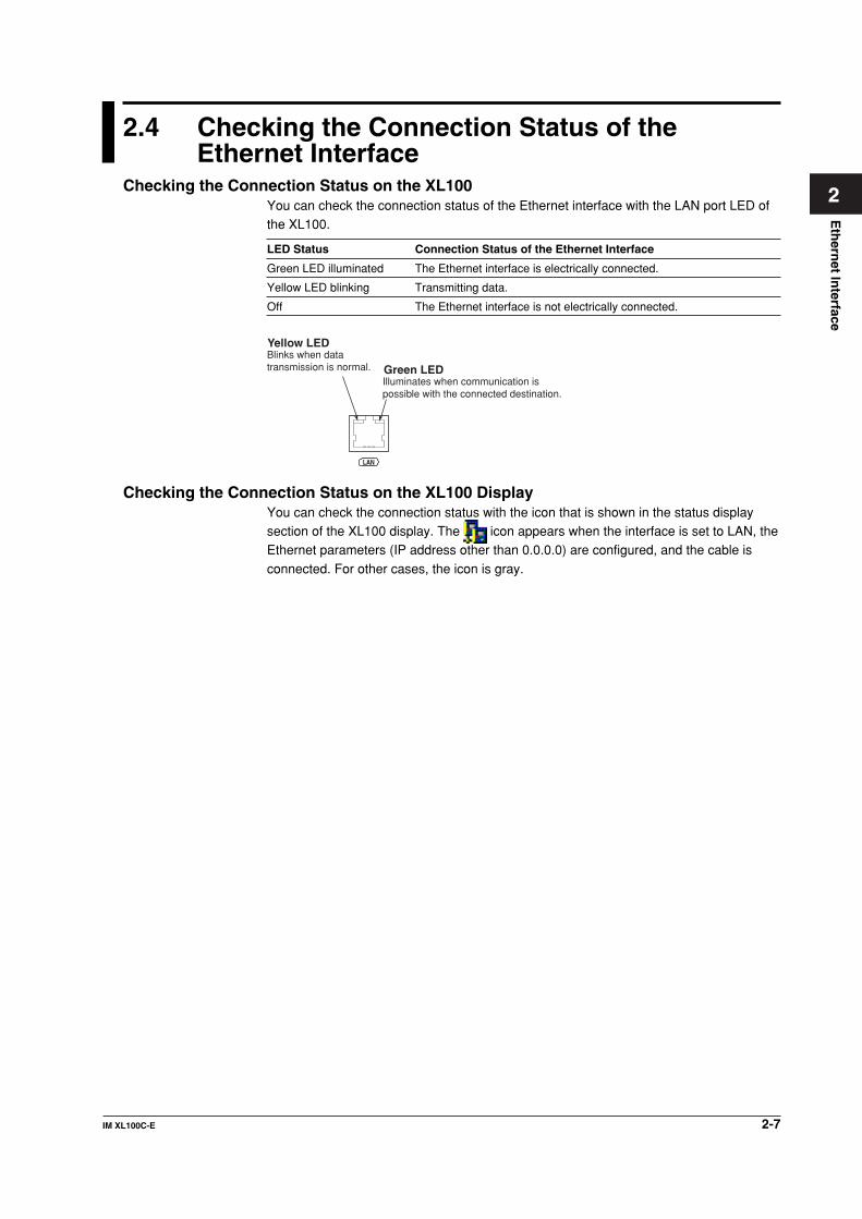
Checking the Connection Status on the XL100You can check the connection status of the Ethernet interface with the LAN port LED ofthe XL100.
LED Status Connection Status of the Ethernet Interface
Green LED illuminated The Ethernet interface is electrically connected.
Yellow LED blinking Transmitting data.
Off The Ethernet interface is not electrically connected.
LAN
Green LEDBlinks when data transmission is normal.
Illuminates when communication is possible with the connected destination.
Yellow LED
Checking the Connection Status on the XL100 DisplayYou can check the connection status with the icon that is shown in the status displaysection of the XL100 display. The icon appears when the interface is set to LAN, theEthernet parameters (IP address other than 0.0.0.0) are configured, and the cable is
connected. For other cases, the icon is gray.

2-8 IM XL100C-E
2.5 Setting the FTP Client (Setting the Auto Transferof Measurement and Alarm Data Files)
By setting this function, the measurement and alarm data files created in the internal
memory of the XL100 or an external storage medium can be automatically transferredusing FTP at the time the files are created. To use this function, however, the Ethernetinterface must be configured as described in section 2.3.
• Selecting the Transferred Files• You can select whether to automatically transfer the measurement and alarm data
files. The default setting is OFF.• The data files are automatically transferred to the FTP destination explained in the
next section at the end of the logging operation.
NoteIf a file with the same name is detected at the destination, the file is transferred with thelast character of the file name changed.
Example: If the file to be transferred named “050714130440.DLO” exists at thedestination, the file name is changed to “050714130441.DLO” before it istransferred.
• Setting the FTP DestinationConsult your system or network administrator when setting parameters such as theprimary/secondary FTP servers, port number, login name, password, account, and
availability of the PASV mode.
• Specifying Primary and SecondaryYou can specify two destination FTP servers, primary and secondary. If the primary
server is down, the file is transferred to the secondary server.• FTP Server Name
Enter the name of the file transfer destination FTP server using up to 64
alphanumeric characters.• If the DNS is used, you can set the host name as a server name.
For details on setting the DNS, see section 2.3, “Setting the Ethernet Interface.”
• You can also set the IP address. In this case, the DNS is not required.• Port Number
Enter the port number of the file transfer destination FTP server in the range of 1 to
65535. The initial value is 21.• Login Name
Enter the login name for accessing the FTP server using up to 32 alphanumeric
characters.• Password
Enter the password for accessing the FTP server using up to 32 alphanumeric
characters.• Account
Enter the account (ID) for accessing the FTP server using up to 32 alphanumeric
characters.• PASV Mode
Turn PASV mode ON when using the XL100 behind a firewall that requires the
passive mode. The default setting is OFF. A firewall is furnished on a router (or asimilar device) that has security features. It prevents intrusion from the outside intothe network system.

2-9IM XL100C-E
Eth
ernet In
terface
1
2
3
4
5
6
7
App
Index
• Initial PathEnter the directory of the file transfer destination using up to 64 alphanumericcharacters. The delimiter for directories varies depending on the implementation ofthe destination FTP server.
Example When transferring files to the “data” directory in the “home” directory ofan FTP server on a UNIX file system.
/home/data
NoteIf the file transfer to both primary and secondary servers fails, the XL100 aborts the filetransfer. When the connection to the destination recovers, the XL100 transfers the datafiles that failed to be transmitted in addition to the new data file.
Procedure
1. Press SETTING to enter Setting Mode.
2. Use the arrow keys to select COMMUNICATION, and press SELECT.
→
3. Use the arrow keys to select NETWORK FUNC., and press SELECT.
→
4. With FTP CLIENT selected, press SELECT.
2.5 Setting the FTP Client (Setting the Auto Transfer of Measurement and Alarm Data Files)

2-10 IM XL100C-E
5. Use the arrow keys to select the desired item, and press SELECT.Press SELECT to show a selection list or window for setting the item.
• Primary server setting display
6. Select or enter the item on the displayed selection list or window.
7. Press SET.
2.5 Setting the FTP Client (Setting the Auto Transfer of Measurement and Alarm Data Files)

2-11IM XL100C-E
Eth
ernet In
terface
1
2
3
4
5
6
7
App
Index
2.6 FTP Test
You can test whether files can be transferred via the Ethernet interface by transferring atest file from the XL100 to the FTP server specified in section 2.5.
• Items to Check before Performing This Test• Connect the Ethernet cable correctly. For the connection procedure, see section
2.2.• Check that the Ethernet interface settings are correct. For the procedure, see
section 2.3 or 2.5.
When setting the Ethernet interface, check the settings with your system or networkadministrator.
• Checking the Results of the FTP Test• When an FTP test is executed, a test file named XL_FTPC.TXT is transferred to
the directory indicated by the initial path at the FTP destination specified in section2.5.
• The result of the FTP test can be confirmed by displaying the FTP log (displayedon the XL100 (see section 2.8)) or Web screen (see section 2.10) or by outputtingthe result using the FL command (see section 4.8).
Procedure
1. Press SETTING to enter Setting Mode.
2. Use the arrow keys to select COMMUNICATION, and press SELECT.
→
3. Use the arrow keys to select NETWORK FUNCTION SETTINGS, and press
SELECT.
→
2-12 IM XL100C-E
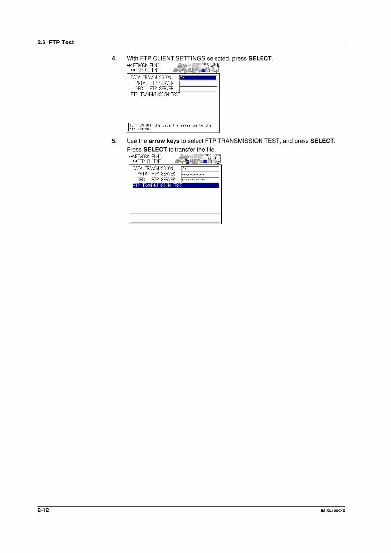
4. With FTP CLIENT SETTINGS selected, press SELECT.
5. Use the arrow keys to select FTP TRANSMISSION TEST, and press SELECT.Press SELECT to transfer the file.
2.6 FTP Test

2-13IM XL100C-E
Eth
ernet In
terface
1
2
3
4
5
6
7
App
Index
2.7 Setting the Login and Timeout Functions ofEthernet Communications
By setting these functions, you can prohibit invalid access from the network to the
XL100, authorize setup operations of the XL100 via the Ethernet network, anddisconnect connections if there is no data transmission for a certain time. To use thisfunction, however, the Ethernet interface must be configured as described in section 2.3.
Registering Users• Selecting the User Level
Select either user level, administrator or user.• Administrator
One administrator can be registered. The administrator has the privileges to use
all the functions of the setting/measurement server, maintenance/test server,and FTP server.
• User
Certain limitations exist in using the setting/measurement server, maintenance/test server, and FTP server.• Limitations on the use of the setting/measurement server
Users are not authorized to change the settings that would change theoperation of the XL100. Users can output measured and setting data.
• Limitations on the use of the maintenance/test server
A user cannot disconnect a connection between another PC and the XL100.A user can disconnect the connection between the PC that the user is usingand the XL100.
• Limitations on the use of the FTP serverA user cannot save files to the external storage medium of the XL100 ordelete files on it. A user can load files.
• Selecting Whether to Register (ON/OFF) Users• ON
Registers users. You can set the user name and password for logging in.
• OFFNot register users.
• Setting the User Name• Enter the user name using up to 16 alphanumeric characters.• You cannot register the same user names.• Since the word “quit” is reserved as a command on the XL100, the user name
“quit” is not allowed.• Setting the Password
Set the password using up to six alphanumeric characters.

2-14 IM XL100C-E
Note• The relationship between the login function and the user name for accessing the XL100
is as follows:• When the login function is set to ON
• You can log in to the XL100 using the registered user name and password.• The user level is the user level specified when the user name was registered.
• When the login function is set to OFF• You can log in to the XL100 as an administrator by accessing the XL100 using the
user name “admin.” No password is necessary.• You can log in to the XL100 as a user by accessing the XL100 using the user name
“user.” No password is necessary.• The user name “anonymous” has a special meaning only when the FTP server function
of the XL100 is used.• When the login function is set to ON
• If a user name “anonymous” is registered to the XL100, you can log in to the XL100using the user name “anonymous”.
• No password is necessary (you can log in regardless of whether a password isentered).
• The user level is set to the level of the user that registers “anonymous.”• When the login function is set to OFF
• You can login using the user name “anonymous”.• No password is necessary (you can log in regardless of whether a password is
entered).• The user level is set to user.
• There is a limitation on the number of simultaneous connections and the number ofsimultaneous users accessing the XL100 (see section 2.1).
• For a description of the login process of the Setting/Measurement server andMaintenance/Test server, see appendix 2, “Login Process.”
Procedure
1. Press SETTING to enter Setting Mode.
2. Use the arrow keys to select SYSTEM, and press SELECT.
→
3. With USER REGISTER selected, press SELECT.
4. Use the arrow keys to select the desired user, and press SELECT.
5. In the window shown, set the items, and press SELECT.
6. Press SET.
2.7 Setting the Login and Timeout Functions of Ethernet Communications

2-15IM XL100C-E
Eth
ernet In
terface
1
2
3
4
5
6
7
App
Index
2.8 Showing the Error, Communication, and FTPLog Displays
• Showing the Error Log DisplayThe error log display shows a log of operation errors. Up to 50 operation error logs areretained. Logs that exceed 50 are cleared from the oldest data.
31 2 4
1. Last line log No./total number of logsDisplays the log No. shown at the last line of the display and the total number of logs(up to 50*).* If the total number of logs exceeds 50, the log is deleted from the oldest one.
2. Date/Time of error occurrenceDisplays the date/time when the error occurred.
3. Error code4. Error Message
• Showing the Communication Log DisplayThe communication log display shows a log of communication interface I/O
operations. Up to a total of 50 logs is retained. Logs that exceed 50 are cleared fromthe oldest data.
31 2 4 5
1. Last line log No./total number of logsDisplays the log No. shown at the last line of the display and the total number of logs(up to 50*).* If the total number of logs exceeds 50, the log is deleted from the oldest one.
2. Date/Time of accessDisplays the date/time when the user connected and accessed the XL100.
3. Connection user ID numberDisplays the ID number (1 to 7) of the user connected to the XL100.
4. Input or output>: Input. <: Output.
5. MessageDisplays the message (up to 20 characters).

2-16 IM XL100C-E
• Showing the FTP Log DisplayThe FTP log display shows a log of file transfers. Up to 50 file transfer operation logs
are retained. Logs that exceed 50 are cleared from the oldest data.
31 2 4 5
1. Last line log No./total number of logsDisplays the log No. shown at the last line of the display and the total number of logs
(up to 50*).* If the total number of logs exceeds 50, the log is deleted from the oldest one.
2. Date/Time of the file transferDisplays the date/time when the file was transferred to the FTP server.
3. Error codeFor a description of errors, see chapter 8, “Error Messages.”
4. Destination FTP serverP: Primary. S: Secondary.
5. File nameDisplays the name of the transferred file (12 characters).
• Showing the Web Browser Operation Log DisplayYou can display a log (record) of the operations carried out using the Web screen on
the Web operation log display. Up to 50 previous operations are logged. Logs thatexceed 50 are cleared from the oldest data.
31 2 4 5
1. Last line log No./total number of logsDisplays the log No. shown at the last line of the display and the total number of logs(up to 50*).* If the total number of logs exceeds 50, the log is deleted from the oldest one.
2. Date/Time of Web screen operationDisplays the date/time when a operation was carried out on the Web screen.
3. Operation4. Error code
For a description of errors, see chapter 8, “Error Messages.”5. Operation type
2.8 Showing the Error, Communication, and FTP Log Displays

2-17IM XL100C-E
Eth
ernet In
terface
1
2
3
4
5
6
7
App
Index
• Showing the E-mail Log DisplayYou can show a log (record) of e-mail transmissions on the e-mail log display. Up to
50 previous e-mail transmissions are logged. Logs that exceed 50 are cleared fromthe oldest data.
31 2 4 5 6
1. Last line log No./total number of logsDisplays the log No. shown at the last line of the display and the total number of logs(up to 50*).* If the total number of logs exceeds 50, the log is deleted from the oldest one.
2. Date/time of e-mail transmissionDisplays the date/time of e-mail transmission.
3. E-mail timingDisplays the e-mail transmission timing (periodic, power failure, alarm, etc.).
4. Error codeFor a description of errors, see chapter 8, “Error Messages.”
5. Recipient No.1: Recipient 1. 2: Recipient 2
6. Error description
Note• There is also a log display that shows a log of key login operations.
• You can also use commands to output the error, communication, FTP, Web operation, ande-mail log data.
Procedure
1. Press DISPLAY to show a pop-up menu for switching the display.
2. Use the arrow keys to select the desired log display, and press SELECT.
2.8 Showing the Error, Communication, and FTP Log Displays

2-18 IM XL100C-E
2.9 Setting the Web Server Function
To use the Web server function, set the following parameters in addition to thosedescribed in section 2.3, “Setting the Ethernet Interface.”
• Enabling/Disabling the Web Server FunctionSelect ON (enable) or OFF (disable).
• Page Type (Type of Screen to Be Displayed)• Monitor
• The screen displayed on the XL100 is displayed.
• The following information can be displayed.• Alarm summary• Measured and calculated data of all channels
• Logs (message log, error log, key login log, FTP log, e-mail log, and Weboperation log)
• For display examples, see section 2.10.
• OperatorThe following operations can be carried out in addition to the functions available on
the monitor page.
• Switch the display on the XL100 by specifying the display type (trend, digital, orbar graph) and group.
• All operations except the HOLD key operation can be carried out.
• Monitor Page• Enabling/Disabling the Monitor Page
• ON
The monitor page can be displayed on a Web browser.• OFF
Disables the monitor page.
• Enabling/Disabling Access Control• ON
Enables access control. You must enter the user name and password to display
the monitor page.• OFF
Disables access control.
• Setting the User NameEnter the user name using up to 16 characters.
• Setting the PasswordEnter the password using up to six alphanumeric characters.
• Operator Page• Enabling/Disabling the Operator Page
• ONThe operator page can be displayed on the browser.
• OFFDisables the operator page.
• Enabling/Disabling Access Control• ON
Enables access control. You must enter the user name and password to displaythe operator page.
• OFFDisables access control.

2-19IM XL100C-E
Eth
ernet In
terface
1
2
3
4
5
6
7
App
Index
• Setting the User NameEnter the user name using up to 16 characters.
• Setting the PasswordEnter the password using up to six alphanumeric characters.
• Saving the SettingsTo activate the settings that have been changed in the basic setting mode, thesettings must be saved. Otherwise, the settings that existed before the change areactivated.
Procedure
1. Press SETTING to enter Setting Mode.
2. Use the arrow keys to select COMMUNICATION, and press SELECT.
→
3. Use the arrow keys to select NETWORK FUNC., and press SELECT.
→
4. Use the arrow keys to select WEB SERVER, and press SELECT.
→
5. Use the arrow keys to select the desired item, and press SELECT.
Press SELECT to show a selection list or window for setting the item.
2.9 Setting the Web Server Function

2-20 IM XL100C-E
6. Select or enter the item on the displayed selection list or window.
7. Press SET.
2.9 Setting the Web Server Function
2-21IM XL100C-E
Eth
ernet In
terface
1
2
3
4
5
6
7
App
Index
2.10 Showing and Using the Monitor or OperatorPage
This section describes how to show the monitor page and operator page on the Web
browser and the operation on each page.
• Web Browsers That Can Be UsedOperations have been confirmed on the following Web browser.• Microsoft Internet Explorer 6.0
• Setting the URLSet the URL (Uniform Resource Locator) appropriately according to the networkenvironment that you are using. You can access the XL100 by setting the URL as
follows:http://host name.domain name/file name• http: Protocol used to access the server. HTTP stands for HyperText Transfer
Protocol.• Host name.domain name: Host name and domain name of the XL100. You can
also use the IP address in place of the host name and domain name.
• File name: File name of the monitor page and operator page of the XL100.File name of the monitor page: monitor.htmFile name of the operator page: operator.htmOmitting the file name is equivalent to specifying the monitor page. However, if themonitor page is disabled, it is equivalent to specifying the operator page.
ExampleTo display the operator page using Internet Explorer on a PC in the same domain asthe XL100 (the domain name, host name, and IP address are assumed to begood.com, XL, and 123.45.67.89, respectively).
URL: http://XL.good.com/operator.htm orURL: http://123.45.67.89/operator.htm
• Contents of the Monitor Page• Display Shown by the XL100
• The display shown on the XL100 (waveform, digital, bar graph, review, alarm
summary, or log) is displayed on the monitor page.• If the XL100 is in the Setting Mode or File Operation Mode, the monitor page
cannot be displayed. An error message is displayed.
• Refreshing the Monitor PageThe monitor page can be refreshed automatically or manually.• Auto refresh ON
The monitor page is refreshed at the specified interval selected from 2, 5, 10, or30 s.
• Auto refresh OFF
The monitor page is not automatically refreshed. You can refresh the pagemanually. Within 2 s of the last refreshing, the page is not refreshed even if youattempt to refresh the page manually.
• Zooming in or out of the DisplayThe display shown on the XL100 can be expanded to 200%.

2-22 IM XL100C-E
• Contents of the Operator PageOn the operator page, the following operations can be carried out in addition to theinformation available on the monitor page.
Switching to Setting Mode or File Operation ModeYou can switch the XL100 to Setting Mode or File Operation Mode, and carry outoperations in the same fashion as when operating the XL100 directly using keys.
2.10 Showing and Using the Monitor or Operator Page
2-23IM XL100C-E
Eth
ernet In
terface
1
2
3
4
5
6
7
App
Index
2.11 Setting the E-mail Transmission Function
To use the e-mail transmission function, set the following parameters in addition to thosedescribed in section 2.3, “Setting the Ethernet Interface.”
• Basic Settings of E-mail Transmission• SMTP* Server Name
Set the SMTP server name (up to 64 alphanumeric characters) or the IP address ofthe SMTP server.* Simple Mail Transfer Protocol
• Port NumberSet the port number to be used. The default setting is 25.
• Recipient 1Set the recipient of the e-mail message using up to 150 alphanumeric characters.You can specify multiple addresses. To specify multiple addresses, delimit theaddresses using spaces.
• Recipient 2Set the recipient of the e-mail message using up to 150 alphanumeric characters.You can specify multiple addresses. To specify multiple addresses, delimit the
addresses using spaces.• Sender
Set the e-mail address that has been provided by the network administrator using
up to 64 alphanumeric characters. If omitted, the sender is set to the first addressspecified as the recipient.
• Settings for Transmitting Alarm Information• Recipient 1, Recipient 2
You can turn ON/OFF the function for each recipient.• ON
Transmits e-mail messages to the recipient.• OFF
Does not transmit e-mail messages to the recipient.
• Contents of the Transmitted Mail• Add Inst. Data
• ON
The instantaneous values of all channels are included in the e-mail message.• Off
The instantaneous values are not included in the e-mail message.
• Add Source URL (Uniform Resource Locator)• ON
If the Web server function is specified on the XL100, the URL of the XL100 is
attached to the e-mail.• OFF
The URL of the XL100 is not attached to the e-mail.
• SubjectSet the subject of the e-mail message using up to 32 alphanumeric characters.The default setting is “(XL100)Alarm_summary.”
• Header 1Set the string to be attached to the e-mail message using up to 64 alphanumericcharacters.
• Header 2Set the string to be attached to the e-mail message using up to 64 alphanumericcharacters.

2-24 IM XL100C-E
• Settings When Transmitting E-mail Messages at the Specified Time• Recipient 1, Recipient 2
You can turn ON/OFF the function for each recipient.• ON
Transmits e-mail messages to the recipient.
• OFFDoes not transmit e-mail messages to the recipient.
• IntervalTime interval used to repeat the e-mail transmission starting from theREFERENCE TIME. Select from the following:1h, 2h, 3h, 4h, 6h, 8h, 12h, or 24h
• REFERENCE TIMEThe time when the e-mail message is to be transmitted. In addition, the e-mailtransmission is repeated at the specified interval from this point. Specify the time in
the following range for each recipient.00:00 to 23:59Example: If Reference time is 17:15 and Interval is 8h, e-mail messages are
transmitted at 17:15, 01:15, and 09:15.• Contents of the Transmitted Mail
• Add Inst. Data• ON
Attaches to the e-mail message the instantaneous values of all channelsexisting at the time of e-mail transmission.
• OFFThe instantaneous values are not attached to the e-mail message.
• Add Source URL (Uniform Resource Locator)• ON
If the Web server function is specified on the XL100, the URL of the XL100 isattached to the e-mail.
• OFFThe URL of the XL100 is not attached to the e-mail.
• SubjectSet the subject of the e-mail message using up to 32 alphanumeric characters.The default value is “(XL100)Periodic_data.”
• Header 1Set the string to be attached to the e-mail message using up to 64 alphanumericcharacters.
• Header 2Set the string to be attached to the e-mail message using up to 64 alphanumericcharacters.
• Settings When Transmitting E-mail Messages at the Time of Recovery from aPower Failure (System Error Settings)For the transmitted contents of the system mail, see section 1.2.• Recipient 1, Sender
You can turn ON/OFF the function for each recipient.• ON
Transmits e-mail messages to the recipient.
• OFFDoes not transmit e-mail messages to the recipient.
2.11 Setting the E-mail Transmission Function
2-25IM XL100C-E
Eth
ernet In
terface
1
2
3
4
5
6
7
App
Index
• Contents of the Transmitted Mail• Include Source URL (Uniform Resource Locator)
• ONIf the Web server function is specified on the XL100, the URL of the XL100 isattached to the e-mail.
• OFFThe URL of the XL100 is not attached to the e-mail.
• SubjectSet the subject of the e-mail message using up to 32 alphanumeric characters.The default setting is “(XL100)System_warning.”
• Header 1Set the string to be attached to the e-mail message using up to 64 alphanumericcharacters.
• Header 2Set the string to be attached to the e-mail message using up to 64 alphanumericcharacters.
Procedure
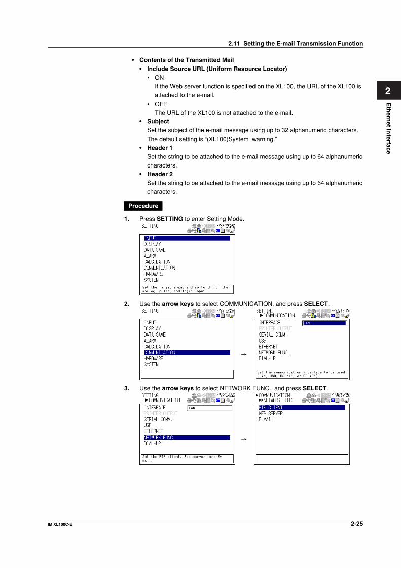
1. Press SETTING to enter Setting Mode.
2. Use the arrow keys to select COMMUNICATION, and press SELECT.
→
3. Use the arrow keys to select NETWORK FUNC., and press SELECT.
→
2.11 Setting the E-mail Transmission Function

2-26 IM XL100C-E
4. Use the arrow keys to select E-MAIL, and press SELECT.
→
5. Use the arrow keys to select the desired item, and press SELECT.Press SELECT to show a window for setting the item.
• Basic setting display
• Alarm information transmission setting display
• Designated time setting page 1/2
• Designated time setting page 2/2
2.11 Setting the E-mail Transmission Function

2-27IM XL100C-E
Eth
ernet In
terface
1
2
3
4
5
6
7
App
Index
• System error transmission setting display
6. Select or enter the item on the displayed selection list or window.
7. Press SET.
2.11 Setting the E-mail Transmission Function

2-28 IM XL100C-E
2.12 E-mail Transmission Test
You can transmit test e-mail messages to recipient 1 or recipient 2 that you specified toconfirm whether e-mail messages can be transmitted.
• Items to Check before Performing This Test• Connect the Ethernet cable correctly. For the connection procedure, see section
2.2.• Check that the Ethernet interface settings are correct. For the procedure, see
section 2.3.
• Check that the e-mail settings are correct. For the procedure, see section 2.11.When setting the Ethernet interface or e-mail, check the settings with your system ornetwork administrator.
• Checking the Results of the E-mail Transmission Test• The result of the e-mail transmission test can be confirmed by displaying the e-mail
log (displayed on the XL100 (see section 2.8)) or Web screen (see section 2.10) orby outputting the result using the FL command (see section 5.9).
• If an error message is displayed on the XL100, see chapter 8, “Error Messages.”
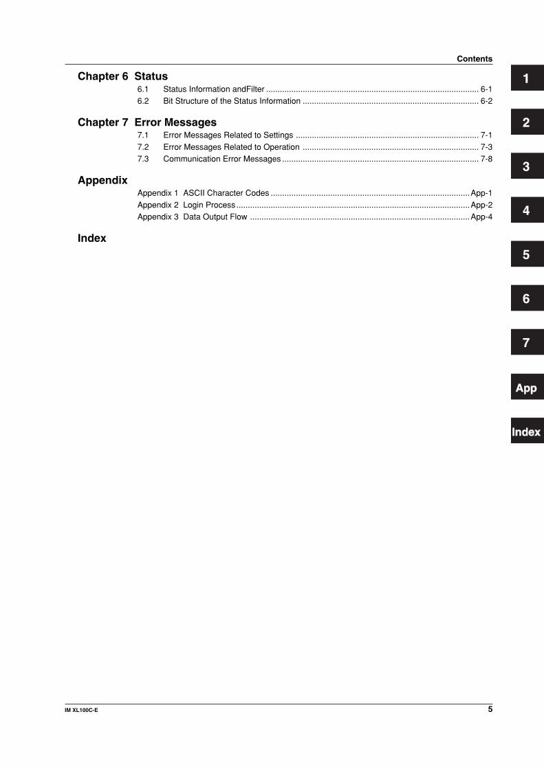
• Contents of the Test E-mail MessageThe figure below shows the contents of the test e-mail message.
From: [email protected]: Mon, 5 Dec 2005 07:15:41 +0900 (JST)Subject: (XL) Test_mailTo: [email protected]
Test mail<Host name>XL<Time of transmission>12/05 07:15:35
Test mail example
Procedure
1. Press SETTING to enter Setting Mode.

2-29IM XL100C-E
Eth
ernet In
terface
1
2
3
4
5
6
7
App
Index
2. Use the arrow keys to select COMMUNICATION, and press SELECT.
→
3. Use the arrow keys to select NETWORK FUNC., and press SELECT.
→
4. Use the arrow keys to select E-MAIL , and press SELECT.
→
5. With BASIC selected, press SELECT.
6. Use the arrow keys to select E-MAIL TRANSMISSION TEST, and press SELECT.
Press SELECT to send the mail.
2.12 E-mail Transmission Test

2-30 IM XL100C-E
2.13 Starting/Stopping E-mail Transmissions
• Starting/Stopping E-mail Transmissions• If E-MAIL SETTINGS > BASIC SETTINGS > E-MAIL TRANSMISSION is turned
ON, the e-mail transmission function is enabled.• If E-MAIL SETTINGS > BASIC SETTINGS > E-MAIL TRANSMISSION is turned
OFF, the e-mail transmission function is disabled. Unsent e-mail messages are
cleared.
Note• If the XL100 enters the basic setting mode while the e-mail transmission is turned ON,
the e-mail transmission is stopped. If the XL100 returns to the operation mode from thebasic setting mode, the condition that existed before entering the basic setting mode isresumed.
• If e-mail transmission fails, the message is retransmitted up to twice at 30-s intervals. Ifretransmission fails, the e-mail message is discarded.
• Contents of the E-mail MessageThe figure below shows examples of an e-mail messages.• Alarm mail example
From: [email protected]: Fri, 5 Aug 2005 08:12:48 +0900 (JST)Subject: (XL) Alarm_summaryTo: [email protected], [email protected]
LOOP1TEMPERATURE
Alarm summary<Host name>XL
<CH>02<Type>1L<On>08/05 08:10:13<Off>08/05 08:12:07
<Instantaneous value>08/05 08:12:0701=0.021V02=-0.041V03=-0.011V • •29=-0.541V30=-0.546V
The XL100 display can be seen at the following URL.http://XL.good.co.jp/
Header 1
Subject
Header 2
Channel numberNumber/Type
Date/Time of alarm occurrence/release
Instantaneous value(When Include INST is specified)• Date/Time• Channel number• Instantaneous value
URL(When Include source URL is specified)
• System mail example
From: [email protected]: Fri, 5 Aug 2005 08:12:48 +0900 (JST)Subject: (XL) System_warningTo: [email protected], [email protected]
LOOP1RAW MATERIAL
Memory full<Host name>XL
08/05 08:12:48<Media remaining> 53 KB<Memory remaining> 1 hour
Header 1
Subject
Header 2
The reason for the e-mail transmission
Detailed message(Media remaining is output when an external storage medium is inserted in the slot when data is saved.)
3-1IM XL100C-E
1
2
3
4
5
6
7
App
Index
Serial In
terface
3.1 RS-232 Interface Specifications and SetupProcedure
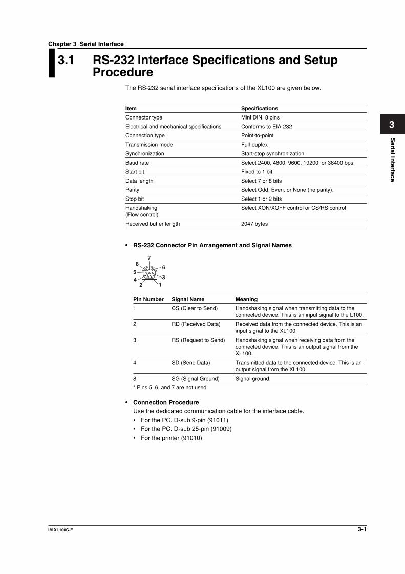
The RS-232 serial interface specifications of the XL100 are given below.
Item Specifications
Connector type Mini DIN, 8 pins
Electrical and mechanical specifications Conforms to EIA-232
Connection type Point-to-point
Transmission mode Full-duplex
Synchronization Start-stop synchronization
Baud rate Select 2400, 4800, 9600, 19200, or 38400 bps.
Start bit Fixed to 1 bit
Data length Select 7 or 8 bits
Parity Select Odd, Even, or None (no parity).
Stop bit Select 1 or 2 bits
Handshaking Select XON/XOFF control or CS/RS control(Flow control)
Received buffer length 2047 bytes
• RS-232 Connector Pin Arrangement and Signal Names
13
6
78
54
2
Pin Number Signal Name Meaning
1 CS (Clear to Send) Handshaking signal when transmitting data to theconnected device. This is an input signal to the L100.
2 RD (Received Data) Received data from the connected device. This is aninput signal to the XL100.
3 RS (Request to Send) Handshaking signal when receiving data from theconnected device. This is an output signal from theXL100.
4 SD (Send Data) Transmitted data to the connected device. This is anoutput signal from the XL100.
8 SG (Signal Ground) Signal ground.
* Pins 5, 6, and 7 are not used.
• Connection ProcedureUse the dedicated communication cable for the interface cable.• For the PC. D-sub 9-pin (91011)
• For the PC. D-sub 25-pin (91009)• For the printer (91010)
Chapter 3 Serial Interface

3-2 IM XL100C-E
Handshaking MethodWhen using the RS-232 interface for transferring data, it is necessary for equipment on
both sides to agree on a set of rules to ensure the proper transfer of data. The set ofrules is called handshaking. Because there are various handshaking methods that canbe used between the XL100 and the PC, you must make sure that the same method is
chosen by both the XL100 and the PC.You can choose any of the three methods on the XL100 in the table below.
Data Sending Control(Control used when sending data to a PC)
Data Receiving Control(Control used when receiving data from a PC)
Software Handshaking
Software Handshaking
Table of Handshaking Methods (Yes indicates that it is supported)
OFF
XON/XOFF
CS/RS
HandshakingStops transmission when X-OFF is received. Resume when X-ON is received.
Stops sending when CS (CTS) is false. Resumes when it is true.
No handshaking
No handshaking
Sends X-OFF when the receive data buffer is 3/4 full. Sends X-ON when the receive data buffer is 1/4th full.
Sets RS (RTS) to False when the receive data buffer is 3/4 full. Sets RS (RTS) to True when the receive data buffer becomes 1/4 full.
Hardware Handshaking
Hardware Handshaking
• OFF• Data transmission control
There is no handshaking between the XL100 and the PC. The “X-OFF” and “X-ON”signals received from the PC are treated as data, and the CS signal is ignored.
• Data reception controlThere is no handshaking between the XL100 and the PC. When the received bufferbecomes full, all of the data that overflows are discarded.
RS = True (fixed).
• XON/XOFF• Data transmission control
Software handshaking is performed between the XL100 and the PC. When an “X-OFF” code is received while sending data to the PC, the XL100 stops the data
transmission. When the XL100 receives the next “X-ON” code, the XL100 resumesthe data transmission. The CS signal received from the PC is ignored.
• Data reception control
Software handshaking is performed between the XL100 and the PC. When the freearea of the received buffer decreases to 1537 bytes, the XL100 sends an “X-OFF”code. When the free area increases to 511 bytes, the XL100 sends an “X-ON”
code.RS = True (fixed).
• CS/RS• Data transmission control
Hardware handshaking is performed between the XL100 and the PC. When the CSsignal becomes False while sending data to the PC, the XL100 stops the data
transmission. When the CS signal becomes True, the XL100 resumes the datatransmission. The “X-OFF” and “X-ON” signals received from the PC are treated asdata.
• Data reception controlHardware handshaking is performed between the XL100 and the PC. When thefree area of the received buffer decreases to 1537 bytes, the XL100 sets
“RS=False.” When the free area increases to 511 bytes, the XL100 sets“RS=True.”
3.1 RS-232 Interface Specifications and Setup Procedure

3-3IM XL100C-E
1
2
3
4
5
6
7
App
Index
Serial In
terface
Precautions Regarding Data Reception ControlWhen handshaking is used to control the reception of data, data may still be sent from
the PC even if the free space in the receive buffer drops below 256 bytes. In this case,after the receive buffer becomes full, the excess data will be lost, whether or nothandshaking is in effect. Data storage of data resumes when there is free space in the
buffer.
Setting the RS-232 Interface• Selecting the Slave Address
Select the address from the following values.1 to 32
• Selecting the Baud RateSelect the baud rate from the following:1200, 2400, 4800, 9600, 19200, or 38400
• Setting the Data LengthSelect the data length from below. To output data in binary format, be sure to set the
data length to 8 bits.7 or 8
• Setting the Stop BitSelect the stop bit from the following:1 or 2
• Selecting the Parity CheckSelect the parity check from the following:ODD, EVEN, or NONE
• Selecting the handshakingSelect the handshaking method from the following.OFF, XON/XOFF, or CS/RS
Procedure
1. Press SETTING to enter Setting Mode.
2. Use the arrow keys to select COMMUNICATION, and press SELECT.
→
3.1 RS-232 Interface Specifications and Setup Procedure

3-4 IM XL100C-E
3. Use the arrow keys to select SERIAL COMM., and press SELECT.
→
4. With PARAMETERS selected, press SELECT.Press SELECT to showPARAMETERS setting window.
5. Select or enter the item on the displayed selection list or window.
6. Press SET.
3.1 RS-232 Interface Specifications and Setup Procedure

3-5IM XL100C-E
1
2
3
4
5
6
7
App
Index
Serial In
terface
3.2 RS-485 Interface Specifications and SetupProcedure
Specifications
Item Specifications
Terminal block type Number of terminals: 6, terminal attachment screws:ISO M4/nominal length of 6 mm
Electrical and mechanical specifications Conforms to the EIA-485 (RS-485)
Connection type Multi-drop (1:32)
Transmission mode Half-duplex
Synchronization Start-stop synchronization
Baud rate Select 1200, 2400, 4800, 9600, 19200, 38400, 57600,or 115200 bps
Start bit Fixed to 1 bit
Data length Select 7 or 8 bits
Parity Select Odd, Even, or None (no parity).
Stop bit Fixed to 1 bit
Received buffer length 2047 bytes
Escape sequence Open and close
Electrical characteristics Three terminals, SG, +, and –
Communication distance Up to 1.2 km (when using two shielded twisted-paircables, AWG 24)
Terminator External: 120 Ω recommended, 1/2W (connectexternally between the + and – terminals)
• RS-485 Terminal Arrangement and Signal NamesSG
Signal Name Meaning
+ Data (+).
– Data (–).
SG (Signal Ground) Signal ground.
Connection ProcedureUp to 31 stations can be connected to a host calculater. The following figure shows anexample when connecting to a PC.
RS-232 / RS-485Converter
+ – SG
SG
XL100
PC
RS-232
Terminator ON
Connect a 120 Ω terminator
Communication cable Communication cable
Pair
Up to 31 stations
XL100XL100
SGSGSG
SGSG

3-6 IM XL100C-E
Setting the RS-485 Interface• Selecting the Slave Address
Select the address from the following values.1 to 32
• Selecting the Baud RateSelect the baud rate from the following:1200, 2400, 4800, 9600, 19200, 38400, 57600, or 115200
• Setting the Data LengthSelect the data length from below. To output data in binary format, be sure to set thedata length to 8 bits.
7 or 8
• Selecting the Parity CheckSelect the parity check from the following:
ODD, EVEN, or NONE
Procedure
1. Press SETTING to enter Setting Mode.
2. Use the arrow keys to select COMMUNICATION, and press SELECT.
→
3. Use the arrow keys to select SERIAL COMM., and press SELECT.
→
3.2 RS-485 Interface Specifications and Setup Procedure

3-7IM XL100C-E
1
2
3
4
5
6
7
App
Index
Serial In
terface
4. Use the arrow keys to select the desired item, and press SELECT.
5. Select the item from the displayed list.
6. Press SET.
3.2 RS-485 Interface Specifications and Setup Procedure

3-8 IM XL100C-E
3.3 USB Communication Specifications and SetupProcedure
When using the USB for serial communication, the XL100 is connected as a device to a
host calculater such as a PC.The only communication protocol that can be used is normal protocol (Yokogawa Meters& Instruments proprietary protocol).
Client End
Item Specifications
Number of ports 1
Electrical and Conforms to USB Rev.1.1mechanical specifications
Connector 5-pin Mini-B receptacle
Power supply Self-powered
PC system supported A PC running Windows 98 SE, Windows Me, Windows 2000, orWindows XP that is equipped with a USB port as standard (aseparate device driver is required for the connection with a PC)
Connection Procedure of the USB Communication InterfaceConnect a USB cable to the Mini-B connector on the XL100 and a USB hub or a type Aconnector of a PC on the host calculater end.
Setting the USB InterfaceSet the following item.Setting the USB IDSet the USB ID number of the XL100 within the following range.00 to 31You can connect multiple devices to a host controller on the USB. If the XL100 is
connected to multiple devices in a single USB system, the USB ID number is used by thehost controller to identify each device. Therefore, unique ID numbers must be assignedto the XL100s within a single system.
NoteDo not change the USB ID number while using the USB.
Procedure
1. Press SETTING to enter Setting Mode.

3-9IM XL100C-E
1
2
3
4
5
6
7
App
Index
Serial In
terface
2. Use the arrow keys to select COMMUNICATION, and press SELECT.
→
3. Use the arrow keys to select USB, and press SELECT.
→
4. Press SELECT to show the USB ID selection list.
5. Use the arrow keys to select the USB ID, and press SELECT.
6. Press SET.
3.3 USB Communication Specifications and Setup Procedure

4-1IM XL100C-E
1
2
3
4
5
6
7
App
Index
Mo
db
us P
roto
col
4.1 Modbus Protocol Specifications and FunctionCodes
The Modbus protocol can be used only on the serial interface (RS-232 or RS-485).
Modbus SpecificationsThe Modbus specifications of the XL100 are as follows:
Specifications Description
Transmission media RS-232 or RS-485
Baud rate Select 1200, 2400, 4800, 9600, 19200, 38400, 57600, or 115200 bps(57600 and 115200 are selectable only on the RS-485)
Start bit Fixed to 1 bit
Stop bit Select 1 or 2 bits
Parity Select Odd, Even, or None (no parity).
Transmission mode RTU (Remote Terminal Unit) mode or ASCII mode
Data length RTU mode: 8 bits. ASCII mode: Select 7 or 8 bits
Error detection RTU mode: Uses error detection CRC-16. ASCII mode: Uses LRC
Data interval RTU mode: Determines message termination with a time intervalequal to 3.5 characters or more.
ASCII mode: Indicates message termination with CR+LF.
Slave address RS-232: 1 to 247RS-485: 1 to 247
Function Codes of the Modbus ProtocolThe function codes of Modbus protocol that the XL100 supports are listed below.Slave FunctionThe slave function of the XL100 does not support broadcast commands.
Function Function OperationCode
3 Read the hold register (4xxxx) The master device can read the communicationinput data written using function codes 6 and 16.
4 Read the input register (3xxxx) The master device loads the calculated,measured, and time data of the XL100.
6 Single write to hold register (4xxxx) The master device writes to the communicationinput data of the XL100.
8 Loopback test The master device performs a loopback test ofthe XL100. The XL100 only supports messagereturn (test code 0x00*).
16 Write to the hold register (4xxxx) The master device writes to the communicationinput data of the XL100.
* Hexadecimal 00.
Master Function
Function Function OperationCode
3 Read the hold register Read the hold register data of another device into(4xxxx and 4xxxxx) communication input data (Cxx).
4 Read the input register Read the input register data of another(3xxxx and 3xxxxx) device into communication input data (Cxx).
Chapter 4 Modbus Protocol
4-2 IM XL100C-E
4.2 Register Assignments (for Modbus Slave)
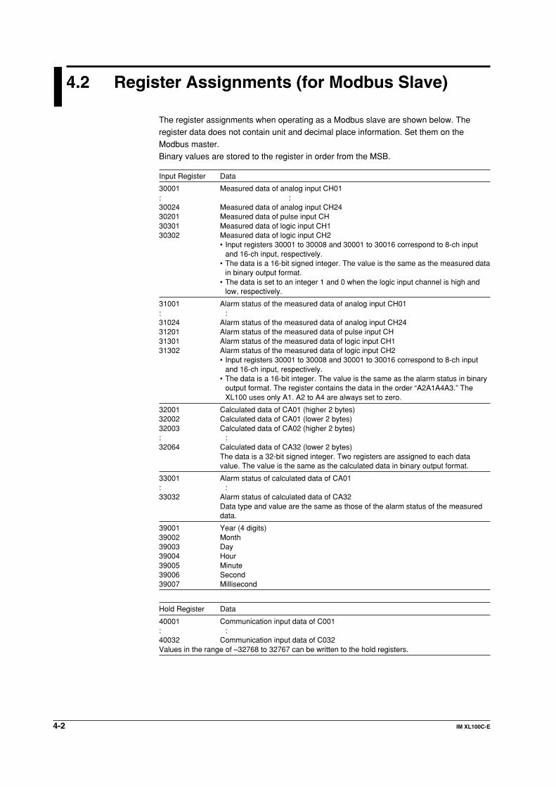
The register assignments when operating as a Modbus slave are shown below. Theregister data does not contain unit and decimal place information. Set them on the
Modbus master.Binary values are stored to the register in order from the MSB.
Input Register Data
30001 Measured data of analog input CH01: :30024 Measured data of analog input CH2430201 Measured data of pulse input CH30301 Measured data of logic input CH130302 Measured data of logic input CH2
• Input registers 30001 to 30008 and 30001 to 30016 correspond to 8-ch inputand 16-ch input, respectively.
• The data is a 16-bit signed integer. The value is the same as the measured datain binary output format.
• The data is set to an integer 1 and 0 when the logic input channel is high andlow, respectively.
31001 Alarm status of the measured data of analog input CH01: :31024 Alarm status of the measured data of analog input CH2431201 Alarm status of the measured data of pulse input CH31301 Alarm status of the measured data of logic input CH131302 Alarm status of the measured data of logic input CH2
• Input registers 30001 to 30008 and 30001 to 30016 correspond to 8-ch inputand 16-ch input, respectively.
• The data is a 16-bit integer. The value is the same as the alarm status in binaryoutput format. The register contains the data in the order “A2A1A4A3.” TheXL100 uses only A1. A2 to A4 are always set to zero.
32001 Calculated data of CA01 (higher 2 bytes)32002 Calculated data of CA01 (lower 2 bytes)32003 Calculated data of CA02 (higher 2 bytes): :32064 Calculated data of CA32 (lower 2 bytes)
The data is a 32-bit signed integer. Two registers are assigned to each datavalue. The value is the same as the calculated data in binary output format.
33001 Alarm status of calculated data of CA01: :33032 Alarm status of calculated data of CA32
Data type and value are the same as those of the alarm status of the measureddata.
39001 Year (4 digits)39002 Month39003 Day39004 Hour39005 Minute39006 Second39007 Millisecond
Hold Register Data
40001 Communication input data of C001: :40032 Communication input data of C032Values in the range of –32768 to 32767 can be written to the hold registers.

4-3IM XL100C-E
1
2
3
4
5
6
7
App
Index
Mo
db
us P
roto
col
4.3 Modbus Error Response (for Modbus Slave)
When using the Modbus slave function, the XL100 returns the error codes below to themaster device. For the error messages related to communications that the XL100
displays, see chapter 8, “Error Messages.”
Code Meaning Cause
1 Bad function code Unsupported function request. For a list of supportedfunctions, see section 4.1, “Modbus Protocol Specificationsand Function Codes.”
2 Bad register number Attempted to read/write to a register that has nocorresponding channel.
3 Bad number of registers The specified number of registers is zero.
However, no response is returned in the following cases.• CRC error• Errors other than those in the above list.

4-4 IM XL100C-E
4.4 Setting the Modbus Master Function
Set the items below to use the Modbus master function.• Communication Interval
The cycle at which data is read from other devices. Select the read cycle from thefollowing:100 ms, 200 ms, 500 ms, 1 s, 2 s, 5 s, or 10 s
• Timeout ValueTimeout occurs if a response is not received from the specified slave device within the
time specified here (timeout value) after a command is sent from the XL100. TheXL100 repeats the operation of sending a command and waiting for a response forthe number of times specified by the retrial value. If no response is received even
after waiting the timeout value for all retrials, the XL100 stops sending commands tothe slave device for a period equal to 10 times the timeout value. Then, the XL100tries again. For details, see section 4.5, “Data Dropout Handling of the Modbus
Master.”Select the timeout time from the following:100 ms, 200 ms, 500 ms, 1 s, 2 s, 5 s, 10 s, or 1 min
• RetrialsThis is the number of times to retransmit the command when there is no responsefrom the specified slave device. If no response is received even after retrying the
number of times specified here, the XL100 stops sending commands to the slavedevice for a period equal to 10 times the timeout value. Then, the XL100 tries again.For details, see section 4.5, “Data Dropout Handling of the Modbus Master.”
Select the number of retrials from the following:OFF (0), 1, 2, 3, 4, 5, 10, or 20
• CommandsThe commands are used to read the data in the register of slave devices into thecommunication input data of the XL100 at the read cycle. Consecutive registers of thesame data type in a slave device can be registered as a single command and read
into consecutive communication input data.• Enabling/Disabling Commands
Turn ON the command registration line to be used. Up to 32 commands can be
registered.• Read channel (First CH, Last CH)
Set the communication input data (CO01 to CO32) to which the data loaded from
the slave device is to be assigned.• Address
Specify the address of the slave device from the following:
1 to 247• Register
Specify the register number of the slave device. Since 32-bit data is assigned to
two registers, specify the smaller register number (see “Type” below).Input register: 30001 to 39999, 300001 to 365535Hold register: 40001 to 49999, 400001 to 465535
• TypeSpecify the data type assigned to the Modbus register of the slave device.• INT16
Specify this type when a “16-bit signed integer” is assigned to the Modbusregister.
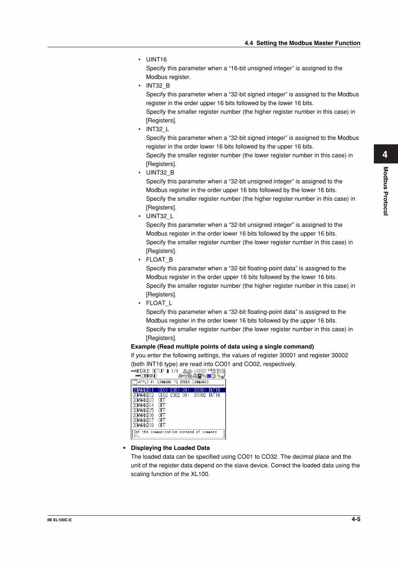
4-5IM XL100C-E
1
2
3
4
5
6
7
App
Index
Mo
db
us P
roto
col
• UINT16Specify this parameter when a “16-bit unsigned integer” is assigned to the
Modbus register.• INT32_B
Specify this parameter when a “32-bit signed integer” is assigned to the Modbus
register in the order upper 16 bits followed by the lower 16 bits.Specify the smaller register number (the higher register number in this case) in[Registers].
• INT32_LSpecify this parameter when a “32-bit signed integer” is assigned to the Modbusregister in the order lower 16 bits followed by the upper 16 bits.
Specify the smaller register number (the lower register number in this case) in[Registers].
• UINT32_B
Specify this parameter when a “32-bit unsigned integer” is assigned to theModbus register in the order upper 16 bits followed by the lower 16 bits.Specify the smaller register number (the higher register number in this case) in
[Registers].• UINT32_L
Specify this parameter when a “32-bit unsigned integer” is assigned to the
Modbus register in the order lower 16 bits followed by the upper 16 bits.Specify the smaller register number (the lower register number in this case) in[Registers].
• FLOAT_BSpecify this parameter when a “32-bit floating-point data” is assigned to theModbus register in the order upper 16 bits followed by the lower 16 bits.
Specify the smaller register number (the higher register number in this case) in[Registers].
• FLOAT_L
Specify this parameter when a “32-bit floating-point data” is assigned to theModbus register in the order lower 16 bits followed by the upper 16 bits.Specify the smaller register number (the lower register number in this case) in
[Registers].Example (Read multiple points of data using a single command)If you enter the following settings, the values of register 30001 and register 30002
(both INT16 type) are read into CO01 and CO02, respectively.
• Displaying the Loaded DataThe loaded data can be specified using CO01 to CO32. The decimal place and theunit of the register data depend on the slave device. Correct the loaded data using thescaling function of the XL100.
4.4 Setting the Modbus Master Function
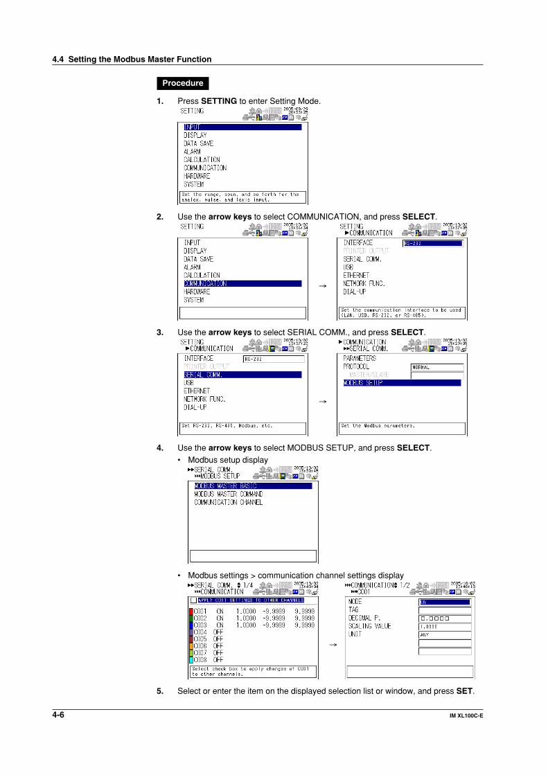
4-6 IM XL100C-E
Procedure
1. Press SETTING to enter Setting Mode.
2. Use the arrow keys to select COMMUNICATION, and press SELECT.
→
3. Use the arrow keys to select SERIAL COMM., and press SELECT.
→
4. Use the arrow keys to select MODBUS SETUP, and press SELECT.
• Modbus setup display
• Modbus settings > communication channel settings display
→
5. Select or enter the item on the displayed selection list or window, and press SET.
4.4 Setting the Modbus Master Function

4-7IM XL100C-E
1
2
3
4
5
6
7
App
Index
Mo
db
us P
roto
col
4.5 Data Dropout Handling of the Modbus Master
If the read cycle is exceeded before the response to the previous command is completedwhen the XL100 is communicating with multiple slave devices, a data dropout occurs
from not being able to send the command within the read cycle.If this happens, change the read cycle, timeout value, and retrials to appropriate settingsby referring to the figure below.
1. When the response from the slave device takes a long time
Read cycle
Data dropout(Slave 2 and 3)
Data dropout(Slave 3)
Slave device 1
Slave device 2
Slave device 3
2. When there is no response from the slave device (retrials = 1)Read cycle
Timeout value
Data dropout(Slave 2 and 3)
Slave device 1
Slave device 2
Slave device 3
3. When the XL100 disconnects the relevant slave device for a period equal to 10times the timeout value and makes a normal recovery at the retrial (disconnectsthe relevant slave device for a period equal to 110 times the timeout value andmakes a normal recovery at the retrial
Read cycle
Data dropout(Slave 2 and 3)
Slave device 1
Slave device 2
Slave device 3
Timeout value Timeout value
Time during which slave 2 is disconnected: 10 times the specified timeout

4-8 IM XL100C-E
After disconnecting slave 2, retry at the first read cycle after a period equal to10 times the specified timeout value
Read cycle
Slave device 1
Slave device 2
Slave device 3
Timeout value
Data dropout(Slave 2 and 3)
Normal recovery
4.5 Data Dropout Handling of the Modbus Master

5-1IM XL100C-E
1
2
3
4
5
6
7
App
Index
Stan
dard
Pro
toco
l
5.1 Command Syntax
The syntax of the setting/basic setting/output commands (see sections 5.3 to 5.10) of theXL100 is given below. ASCII codes (see appendix 1) are used for the character codes.
For the maintenance/test command syntax, see section 5.11.
Command name Parameter
?
Terminator
Delimiter
Sub delimiter
SR 02,SKIP;SR 03,VOLT,2V,-1500,1800Parameter (02 SKIP ... 1800)
Delimiter (,)
Command name (SR)
Sub delimiter (;)
Command example
• Command NameDefined using two alphabet characters.
• Parameters• Command parameters.• Set using alphabet characters or numerical values.• Parameters are separated by delimiters (commas).
• All numerical values are specified using integers.• When the parameter is a numerical value, the valid range of the value varies
depending on the command.
• Spaces around the parameter are discarded. (However, spaces are valid forparameters specified using an ASCII character string.)
• You can omit the parameters that do not need to be changed from their current
settings. However, delimiters cannot be omitted.Example SR 01,,2V<Terminator>
If multiple parameters are omitted and delimiters occur at the end of the command,
those delimiters can be omitted.Example SR 01,VOLT,,,<Terminator> → SR 01,VOLT<Terminator>
• The number of digits of the following parameters is fixed. If the number is exceeded
when entering the command, a syntax error results.• Date YY/MM/DD (8 characters)
YY: Enter the lower two digits of the year.
MM: MonthDD: Day
• Time HH: MM:SS (8 characters)
HH: HourMM: MinuteSS: Second
• Channel number: 2 characters• Alarm output number: 3 characters
Chapter 5 Standard Protocol
5-2 IM XL100C-E
• Query• A question mark is used to specify a query.
• By placing a query after a command or parameter, the setting information of thecorresponding command can be queried. Some commands cannot executequeries. For the query syntax of each command, see section 5.2.
• Delimiter• A comma is used as a delimiter.• Parameters are separated by delimiters.
• Sub Delimiter• A semicolon is used as a sub delimiter.
• By separating each command with a sub delimiter, up to 10 commands can bespecified one after another. However, the commands and queries cannot bespecified one after another. Use them independently.* If there are consecutive sub delimiters, they are considered to be single. In addition, sub
delimiters at the front and at the end are ignored.Example ;SR01,VOLT;;;SR02,VOLT;<terminator> is taken to be
SR01,VOLT;SR02,VOLT<terminator>.
• TerminatorUse either of the following two characters for the terminator.
• CR+LF (0DH 0AH in ASCII code)• LF (0AH in ASCII code)
Note• Do not specify a channel or alarm output number that is not available on the XL100. If
you do, an error will occur.
• The total data length from the first character to the terminator must be less than 2047bytes.
• Commands are not case sensitive (with the exception of user-specified characterstrings).
• All the commands that are listed using sub delimiters are executed even if any of thecommands in the middle is erroneous.
• Spaces that are inserted before and after a parameter are ignored. However, if spaces areinserted before a command, after a sub delimiter, or after a query, an error occurs.
5.1 Command Syntax

5-3IM XL100C-E
1
2
3
4
5
6
7
App
Index
Stan
dard
Pro
toco
l
5.2 Response Syntax
The following table shows the types of responses for various commands.The XL100 returns a response (affirmative/negative response) to a command that is
delimited by a single terminator. The controller should follow the one command to oneresponse format. When the command-response rule is not followed, the operation is notguaranteed.
Command Response Group Affirmation NegationSetting command Setting Control
Affirmative response and
Basic setting command ASCII output response
Negative Output command Control Affirmative response response Setup, measurement, and ASCII output response control data output BINARY output response RS-485 and USB RS-485 and USB response No response
Function
Setting/Measurement server
The syntax of each response is indicated below.Affirmative Response Syntax
When the command is processed correctly, an affirmative response is returned.
• SyntaxE0<CRLF>
• ExampleE0<CRLF>
Negative Response SyntaxSingle Negative Response SyntaxWhen the command is not processed correctly, a single negative response is returned. Fora description of error numbers and error messages, see chapter 8, “Error Messages.”• Syntax
E1_nnn_mmm...m<CRLF>
nnn Error number (001 to 999)mmm...m Message (variable length, one line)
_ Space• Example
E1 001 “System error”
Multiple Negative Response Syntax• If there is an error in any one of the multiple commands that are separated by sub
delimiters, multiple negative responses are returned.• The response is generated for each erroneous command.• If there are multiple commands that have errors, the negative responses are
separated by commas.• The error position number is assigned to the series of commands in order starting with
“1” assigned to the first command.
For a description of error numbers and error messages, see chapter 8, “Error Messages.”• Syntax
E2_ee:nnn<CRLF> (When there is only one error)
E2_ee:nnn,ee:nnn,•••,ee:nnn<CRLF> (When there are multiple errors)ee Error position (01 to 10)nnn Error number (001 to 999)
_ Space• Example
E2 02:001

5-4 IM XL100C-E
ASCII Output Response SyntaxThe basic ASCII output syntax is indicated below.
• SyntaxEA<CRLF>
•••••••••••••••<CRLF>
:
•••••••••••••••<CRLF>
•••••••••••••••<CRLF>
EN<CRLF>
The following types of ASCII data are available.
Query response, decimal place/unit information, measured/calculated data,communication log, FTP log, operation error log, key login log, Web operation log, e-maillog, alarm summary, status information, file list, and user level
Each type of ASCII data is described below.
Query ResponseThe response syntax of the setting corresponding to a command or parameter with aquestion mark is indicated below. For the query syntax of each command, see sections5.4 to 5.11.
• SyntaxEA<CRLF>
...<CRLF>
...
...<CRLF>
EN<CRLF>
• ExampleCommand UE?<CRLF>
Response EA<CRLF>
UE OK<CRLF>
EN<CRLF>
Decimal Place/Unit Information• The FE command is used to output the data.• The measured/calculated data that are output using the FD command contains only
the mantissa. By combining with the binary display data or the decimal place obtainedwith the FE command, the correct measured/calculated data can be derived.
• SyntaxThe data is output for each channel in the following syntax.EA<CRLF>
s_kccuuuuuu,pp<CRLF>
............
EN<CRLF>
s Data status (N, S)
N: NormalS: Skip (when the input range is set to SKIP for a measurement channel)
5.2 Response Syntax
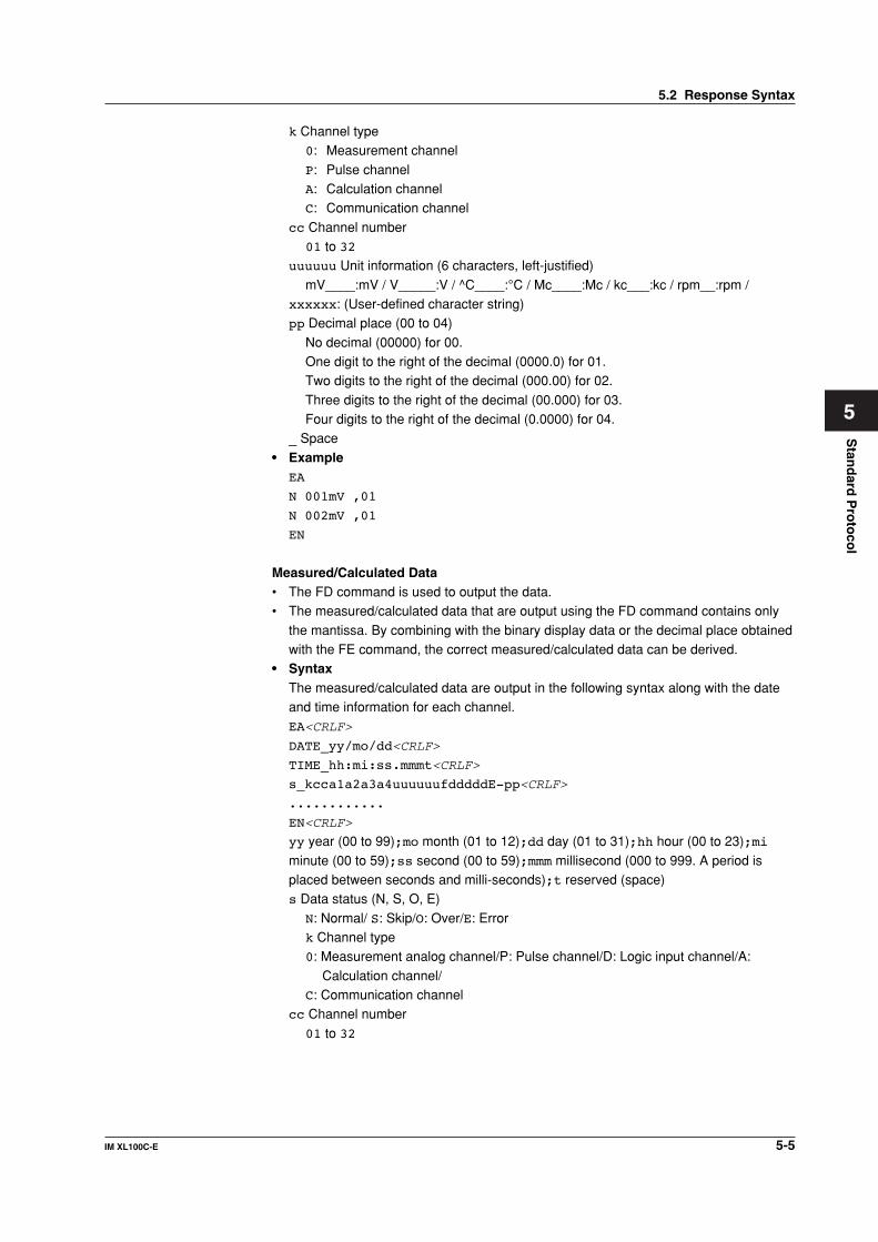
5-5IM XL100C-E
1
2
3
4
5
6
7
App
Index
Stan
dard
Pro
toco
l
k Channel type0: Measurement channel
P: Pulse channelA: Calculation channelC: Communication channel
cc Channel number01 to 32
uuuuuu Unit information (6 characters, left-justified)
mV____:mV / V_____:V / ^C____:°C / Mc____:Mc / kc___:kc / rpm__:rpm /xxxxxx: (User-defined character string)pp Decimal place (00 to 04)
No decimal (00000) for 00.One digit to the right of the decimal (0000.0) for 01.Two digits to the right of the decimal (000.00) for 02.
Three digits to the right of the decimal (00.000) for 03.Four digits to the right of the decimal (0.0000) for 04.
_ Space
• ExampleEA
N 001mV ,01
N 002mV ,01
EN
Measured/Calculated Data• The FD command is used to output the data.• The measured/calculated data that are output using the FD command contains only
the mantissa. By combining with the binary display data or the decimal place obtainedwith the FE command, the correct measured/calculated data can be derived.
• SyntaxThe measured/calculated data are output in the following syntax along with the dateand time information for each channel.EA<CRLF>
DATE_yy/mo/dd<CRLF>
TIME_hh:mi:ss.mmmt<CRLF>
s_kcca1a2a3a4uuuuuufdddddE-pp<CRLF>
............
EN<CRLF>
yy year (00 to 99);mo month (01 to 12);dd day (01 to 31);hh hour (00 to 23);mi
minute (00 to 59);ss second (00 to 59);mmm millisecond (000 to 999. A period isplaced between seconds and milli-seconds);t reserved (space)s Data status (N, S, O, E)
N: Normal/ S: Skip/O: Over/E: Errork Channel type0: Measurement analog channel/P: Pulse channel/D: Logic input channel/A:
Calculation channel/C: Communication channel
cc Channel number
01 to 32
5.2 Response Syntax

5-6 IM XL100C-E
a1a2a3a4
a1 Alarm status
a2 Reserved (space character at all times)a3 Reserved (space character at all times)a4 Reserved (space character at all times)
(H, L, I, O, or space)(H(High limit alarm)/L(Lower limit alarm)/ I(Window IN alarm)/O(Window OUTalarm))
Reserved (h, l, T, t, R, and r)Space (no alarm)uuuuuu Unit information (6 characters, left-justified)
mV____:mV/V_____:V/^C____:°C/Mc____:Mc/kc___:kc/rpm__:rpm/xxxxxx: (User-defined character string)
f Sign (+, -)
ddddd Mantissa (00000 to 99999, 5 digits)• Eight digits for calculated data.• For abnormal data (data status is E) or data of which the mantissa or the exponent
exceeds the range (data status is O), the mantissa is set to 99999 (99999999 forcalculated data).
pp Exponent (00 to 04)
_ Space• Example
EA
DATE 05/10/23
TIME 19:56:32.500
N 001h mV +12345E-03
N 002 mV -67890E-01
S 003
EN
Note• Data for non-existing channels are not output (not even the channel number).
• For channels set to skip, output values from alarm status to exponent are spaces.
Communication Log• The FL command is used to output the data.
• A log of setting/basic setting/output commands and responses is output. Up to 50 logsare retained. Logs that exceed 50 are cleared from the oldest data.
• SyntaxEA<CRLF>
yy/mo/dd_hh:mi:ss_n_uuu...ufd_mmm...m<CRLF>
...............
EN<CRLF>
yy Year (00 to 99)mo Month (01 to 12)
dd Day (01 to 31)hh Hour (00 to 23)mi Minute (00 to 59)
ss Second (00 to 59)
5.2 Response Syntax
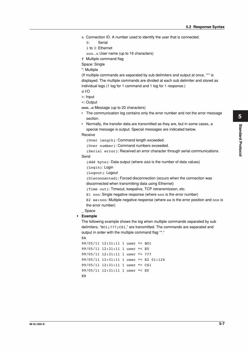
5-7IM XL100C-E
1
2
3
4
5
6
7
App
Index
Stan
dard
Pro
toco
l
n Connection ID. A number used to identify the user that is connected.0: Serial
1 to 3: Ethernetuuu...u User name (up to 16 characters)
f Multiple command flag
Space: Single*: Multiple(If multiple commands are separated by sub delimiters and output at once, “*” is
displayed. The multiple commands are divided at each sub delimiter and stored asindividual logs (1 log for 1 command and 1 log for 1 response.)d I/O
>: Input<: Outputmmm...m Message (up to 20 characters)
• The communication log contains only the error number and not the error messagesection.
• Normally, the transfer data are transmitted as they are, but in some cases, a
special message is output. Special messages are indicated below.Receive
(Over length): Command length exceeded.
(Over number): Command numbers exceeded.(Serial error): Received an error character through serial communications.
Send
(ddd byte): Data output (where ddd is the number of data values)(Login): Login(Logout): Logout
(Disconnected): Forced disconnection (occurs when the connection wasdisconnected when transmitting data using Ethernet)(Time out): Timeout, keepalive, TCP retransmission, etc.
E1 nnn: Single negative response (where nnn is the error number)E2 ee:nnn: Multiple negative response (where ee is the error position and nnn isthe error number)
_ Space• Example
The following example shows the log when multiple commands separated by sub
delimiters, “BO1;???;CS1,” are transmitted. The commands are separated andoutput in order with the multiple command flag “*.”EA
99/05/11 12:31:11 1 user *> BO1
99/05/11 12:31:11 1 user *< E0
99/05/11 12:31:11 1 user *> ???
99/05/11 12:31:11 1 user *< E2 01:124
99/05/11 12:31:11 1 user *> CS1
99/05/11 12:31:11 1 user *< E0
EN
5.2 Response Syntax

5-8 IM XL100C-E
FTP Log• The FL command is used to output the data.
• The FTP client log is output. Up to 50 file transfer logs are retained. Logs that exceed50 are cleared from the oldest data.
• SyntaxEA<CRLF>
yy/mo/dd_hh:mi:ss_nnn_xxxxxxxxx_k_ffffffff_eee<CRLF>
•••••••••••••••
EN<CRLF>
yy Year (00 to 99)mo Month (01 to 12)
dd Day (01 to 31)hh Hour (00 to 23)mi Minute (00 to 59)
ss Second (00 to 59)nnn Error code (001 to 999)xxxxxxxxx Detailed code (9 characters)
k Server type (FTP destination)P: PrimaryS: Secondary
ffffffff File name (8 characters)eee Extension (3 characters)_ Space
• ExampleEA
99/07/26 10:00:00 P 72610000 DDR
99/07/27 10:00:00 P 72710000 DDR
99/07/28 10:00:00 123 HOSTADDR P 72810000 DDR
99/07/29 10:00:00 123 HOSTADDR P 72910000 DDR
EN
Error Message Log• The FL command is used to output the data.• The operation error log is output. Up to 50 operation error logs are retained. Logs that
exceed 50 are cleared from the oldest data.
• Other communication messages (400 to 999) and status messages (500 to 599) arenot output.
• SyntaxEA<CRLF>
yy/mo/dd_hh:mi:ss_nnn_uuu•••u<CRLF>
•••••••••••••••
EN<CRLF>
yy Year (00 to 99)
mo Month (01 to 12)dd Day (01 to 31)hh Hour (00 to 23)
mi Minute (00 to 59)ss Second (00 to 59)nnn Error code (001 to 999)
uuu...u Error message (up to 80 characters)
5.2 Response Syntax

5-9IM XL100C-E
1
2
3
4
5
6
7
App
Index
Stan
dard
Pro
toco
l
_ Space• Example
EA
99/05/11 12:20:00 212 “Format error.”
99/05/11 12:30:00 217 “Unknown file type.”
EN
Key Login Log• The FL command is used to output the data.• A log of users that have logged in and logged out is output. Up to 50 login/logout logs
are retained. Logs that exceed 50 are cleared from the oldest data.
• If the power goes down while logged in, you will be logged out. In this case, however,it will not be recorded as a logout.
• User number and user name are not output at the time of the logout.
• SyntaxEA<CRLF>
yy/mo/dd_hh:mi:ss_xxx_nn_uuu•••u<CRLF>
.........................
EN<CRLF>
yy Year (00 to 99)
mo Month (01 to 12)dd Day (01 to 31)hh Hour (00 to 23)
mi Minute (00 to 59)ss Second (00 to 59)xxx Login or log out (In_ or Out). Output left-justified.
nn User number (01 to 07)uuu...u User name (up to 16 characters)_ Space
• ExampleEA
99/05/11 12:20:00 In 01 administrator
99/05/11 12:30:00 Out
99/05/11 12:20:00 In 03 user
99/05/11 12:30:00 Out
EN
Web Operation Log• The FL command is used to output the data.• The log of operations on the Web screen is output. Up to 50 operations are retained.
Logs that exceed 50 are cleared from the oldest data.
• SyntaxEA<CRLF>
yy/mo/dd_hh:mm:ss_ffffff_eee_???...?<CRLF>
..........
EN<CRLF>
5.2 Response Syntax

5-10 IM XL100C-E
yy Year (00 to 99)mo Month (01 to 12)
dd Day (01 to 31)hh Hour (00 to 23)mi Minute (00 to 59)
ss Second (00 to 59)ffffff Requested operationSCREEN: Screen change
KEY: Key operationeee Error code when executing the requested operationAll spaces: Success
001 to 999: Error code???...? Parameter for each cause (see below)• When ffffff = SCREEN
yy/mo/dd_hh:mm:ss_ffffff_eee_ddddd_nnCRLF
ddddd Screen typeTREND: Waveform & digital display
DIGIT: Digital displayBAR: Bar graph displaynn Group number (01 to 04)
• When ffffff = KEYyy/mo/dd_hh:mm:ss_ffffff_eee_kkkkkCRLF
kkkkk Type of key that was operated
ESC: ESC keyHOME: HOME keyREVIEW: REVIEW key
FILE: FILE keySETTING: SETTING keyHOLD: HOLD key
TIMEDIVSHORT: TIME/DIV left keyTIMEDIVLONG: TIME/DIV right keyRANGE: RANGE key
SAVE: SAVE keyDISP: DISPLAY keyGROUP: GROUP key
MARK: MARK keyMARKLEFT: MARK left keyMARKRIGHT: MARK right key
SET : SET keySTARTSTOP: START/STOP keyHOLD: HOLD key
UP: Up arrow keyDOWN: Down arrow keyRIGHT: Right arrow key
LEFT: Left arrow keySELECT: SELECT key
- Space
5.2 Response Syntax

5-11IM XL100C-E
1
2
3
4
5
6
7
App
Index
Stan
dard
Pro
toco
l
• ExampleEA
01/02/11 12:20:00 SCREEN 275 TREND 01
01/02/11 12:21:00 SCREEN BAR 01
01/02/11 12:30:00 KEY UP
01/02/11 12:31:00 KEY RIGHT
01/02/11 12:40:00 MSG 05 Hello-Hello
01/02/11 12:41:00 MSG 05 Hello-Hello
EN
E-mail Log• The FL command is used to output the data.• The e-mail transmission log is output. Up to 50 operations are retained. Logs that
exceed 50 are cleared from the oldest data.
• SyntaxEA<CRLF>
yy/mo/dd_hh:mm:ss_ffffff_eee_n_uuu...u<CRLF>
..........
EN<CRLF>
yy Year (00 to 99)
mo Month (01 to 12)dd Day (01 to 31)hh Hour (00 to 23)
mi Minute (00 to 59)ss Second (00 to 59)ffffff Factor
ALARM: Alarm mailTIME: Scheduled mailREPORT: Reserved
FAIL: Power failure recovery mailFULL: Memory full mailTEST: Test mail
ERROR: Error message maileee Error codeAll spaces: Success
001 to 999: Error coden Recipient list1: List 1
2: List 2+: List 1 and list 2uuu...u Array of recipient e-mail addresses (up to 30 characters)
_ Space• Example
EA
01/05/11 12:20:00 ALARM + notice
01/05/11 12:30:00 REPORT 375 1 user1 user2
EN
5.2 Response Syntax
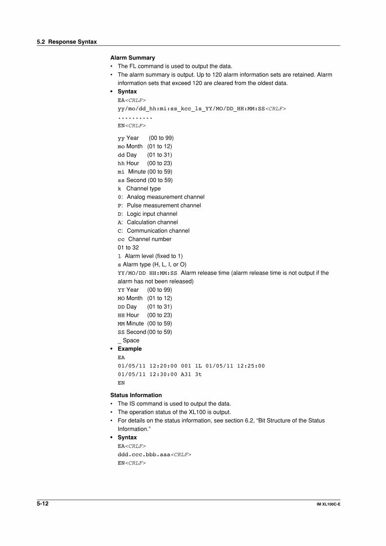
5-12 IM XL100C-E
Alarm Summary• The FL command is used to output the data.
• The alarm summary is output. Up to 120 alarm information sets are retained. Alarminformation sets that exceed 120 are cleared from the oldest data.
• SyntaxEA<CRLF>
yy/mo/dd_hh:mi:ss_kcc_ls_YY/MO/DD_HH:MM:SS<CRLF>
..........
EN<CRLF>
yy Year (00 to 99)mo Month (01 to 12)
dd Day (01 to 31)hh Hour (00 to 23)mi Minute (00 to 59)
ss Second (00 to 59)k Channel type0: Analog measurement channel
P: Pulse measurement channelD: Logic input channelA: Calculation channel
C: Communication channelcc Channel number01 to 32
l Alarm level (fixed to 1)s Alarm type (H, L, I, or O)YY/MO/DD HH:MM:SS Alarm release time (alarm release time is not output if the
alarm has not been released)YY Year (00 to 99)MO Month (01 to 12)
DD Day (01 to 31)HH Hour (00 to 23)MM Minute (00 to 59)
SS Second (00 to 59)_ Space
• ExampleEA
01/05/11 12:20:00 001 1L 01/05/11 12:25:00
01/05/11 12:30:00 A31 3t
EN
Status Information• The IS command is used to output the data.• The operation status of the XL100 is output.• For details on the status information, see section 6.2, “Bit Structure of the Status
Information.”• Syntax
EA<CRLF>
ddd.ccc.bbb.aaa<CRLF>
EN<CRLF>
5.2 Response Syntax

5-13IM XL100C-E
1
2
3
4
5
6
7
App
Index
Stan
dard
Pro
toco
l
aaa Status information 1 (000 to 255)bbb Status information 2 (000 to 255)
ccc Status information 3 (000 to 255)ddd Status information 4 (000 to 255)
• ExampleEA
000.000.032.000
EN
File List• The ME command is used to output the data.
• The file list and the file data sizes of the specified directory on the XL100’s externalstorage medium are output.
• SyntaxEACRLF
ffffffff_eee_ssssssss_yy/mo/dd_hh:mi:ss_llllllllll<CRLF>
.................
zzzzzzz Kbyte free<CRLF>
EN<CRLF>
ffffffff File name (8 characters)
If this is a directory, the characters <DIR> are shown at the position displaying the filedata size.eee Extension (3 characters)
ssssssss Data size of the file (_______0 to 99999999) [byte(s)]yy Year (00 to 99)mo Month (01 to 12)
dd Day (01 to 31)hh Hour (00 to 23)mi Minute (00 to 59)
ss Second (00 to 59)zzzzzzz Free space on the medium (______0 to 9999999)llllllllll ID number (_________0 to 9999999999)
• The ID number is set to a space.• The output is a “0” if the file was saved using another instrument._ Space
• ExampleEA
XV1 DEV 124 99/02/24 20:07:12 12310
XV1 PNL 1204 99/01/19 01:52:37
DATA <DIR> 99/01/19 01:23:64
523 Kbyte free
EN
5.2 Response Syntax

5-14 IM XL100C-E
User Level• The FU command is used to output the data.
• User name, user level, and other information are output.• Syntax
EA<CRLF>
p_l_uuu•••u<CRLF>
EN<CRLF>
p Physical layer
E: EthernetS: RS-232, RS-485, or USB
lUser level
A: Administrator privilegesU: User privileges
uuu...uUser name (up to 16 characters)
_ Space• Example
EA
E A admin
EN
Binary Output Syntax• Basic Syntax
'E' 'B' CR LF
Binary data
ASCII format
Binary format
Data length
Data sum
Flag ID Header sum
1 byte
Binary header(12 bytes)
Binary data
Binary footer(2 bytes)
• EBCRLFIndicates that the data is binary.
• Data LengthThe byte value of “flag + identifier + header sum + binary data + data sum.”
• Header SumThe sum value of “data length + flag + identifier.”
• Binary DataFor the output format of various data types, see section 5.3.
• Data SumThe sum value of binary data.
5.2 Response Syntax

5-15IM XL100C-E
1
2
3
4
5
6
7
App
Index
Stan
dard
Pro
toco
l
• Flag
FlagBit Name (Abbreviation) 0 1 Meaning of the Flag
7 BO MSB LSB Output byte order6 CS No Yes Existence of a checksum5 – – –4 – – –3 – – –2 – – –1 – – –0 END Middle End In the middle or at the end of the continuous data
• When the BO flag is “0,” the MSB is output first. When the BO flag is “1,” the LSB is
output first.• If the check sum is enabled (parameter = 1) using the CS command parameter,
each sum value is inserted in the header sum and data sum sections in the “Basic
Syntax” on the previous page. If the check sum is disabled (parameter = 0), a zerois inserted in the header sum and data sum sections.
• If the amount of data output in response to a ME command is large, not all the data
may be returned in one output request (parameter GET). In this case the END flagbecomes “0.” You must send output requests (parameter NEXT) to receive the restof the data until the END flag becomes “1.”
• The bits that have “–” for the name and flag are not used. The value is undefined.
• Identifier
ID Number Binary Data Type Type Format
0 Undefined file File (*.*) –1 Measured/calculated data Data X2 – – –3 – – –4 Manual sampled data file File (*.*) X5 – – –6 – – –7 – – –8 – – –9 – – –10 – – –11 – – –12 – – –13 Screen image data File (*.*) –
X: Disclosed. –: Common format
• Binary data can be classified by the ID number shown in the table above.• Binary data comes in two types, data and file.
• Data• Measured/calculated data can be output using the FD command.• The data format is disclosed. See the next and subsequent pages.
• File• Display data, event data, TLOG data, and setting data files can be used on
the software program that came with the XL100.
• Files that are in common formats can be opened using software programsthat are sold commercially.
• Other formats are written in ASCII code. A text editor can be used to open
these types of files.• The identifier section in the “Basic Syntax” on the previous page contains the
ID number that indicates the binary data type.
NoteBinary data that is not indicated in the above table is considered undefined files.
5.2 Response Syntax

5-16 IM XL100C-E
• Calculating the Sum ValueIf you set the parameter of the CS command to “1 (enabled),” the checksum value is
output only during serial communications. The check sum is the same as that used inthe TCP/IP and is derived according to the following algorithm.
Buffer on Which the Sum Value Is Calculated• For the header sum, it is calculated from “data length + flag + identifier” (fixed to 6
bytes).• The data sum is binary data.
1 byte
0
(1) (2) (3) (4) (6)(5)
Padding
If the data length of the buffer is odd, a “0” is padded so that it is even. (1) through (6)
are summed as unsigned two-byte integers (unsigned short). If the digit overflows a“1” is added. Finally, the result is bit-wise inverted.
Measured/Calculated Binary Data Syntax• The FD command is used to output the measured/calculated data.• The ID number of the output format is 1.
• The measured data is output using signed 16-bit integer; the calculated data is outputusing signed 32-bit integer. These integers can be understood as physical values byadding the decimal point and the unit. The decimal point position can be determined
using the FE command.
Example of Deriving Physical Values from Binary Data
Binary Data Decimal Position Code Physical Value (Measured Value)
10000 0 10000
10000 1 1000.0
10000 2 100.00
10000 3 10.000
10000 4 1.0000
• Binary Data Format
Number of bytes
2 bytes
Number of blocks
•••Binary data of block n
2 bytes
Binary data of block 1
• Number of BlocksThis is the number of blocks.
• Number of BytesThis is the size of one block in bytes.
5.2 Response Syntax

5-17IM XL100C-E
1
2
3
4
5
6
7
App
Index
Stan
dard
Pro
toco
l
• Block
YearM/C••••••
M/C••••••
MonthChannel
••••••
Channel••••••
DayA2A1
••••••
A2A1••••••
HourA4A3
••••••
A4A3••••••
Minute Millisecond (Reserved)* FlagSecondMeasured data
••••••
Calculated data••••••
1 byte 1 byte 1 byte 1 byte 1 byte 1 byte 2 byte 1 byte 1 byte
4 bytes
* The sections indicated as (Reserved) are not used. The value is undefined.
Block Member
Name Binary Value
Year 0 to 99
Month 1 to 12
Day 1 to 31
Hour 0 to 23
Minute 0 to 59
Second 0 to 59
Millisecond 0 to 999
(Reserved) Undefined
Measurement/Calculation 00H: measurement, 80H: calculation
Channel 01 to 60
Alarm status A1 (Bits 0 to 3) 0 to 11*
Alarm status A2 (Bits 4 to 7) Undefined
Alarm status A3 (Bits 0 to 3) Undefined
Alarm status A4 (Bits 4 to 7) Undefined
* A binary value 0 to 11 is entered in the upper and lower 4 bits of a byte (8 bits) for the alarmstatus. The binary value 0 to 11 correspond to different alarm types, H (high limit alarm), L(low limit alarm, I (window In), and O (window Out) as follows:0: no alarm, 1: H, 2: L, 10: I, and 11: O
• Special Data ValuesThe measured/calculated data take on the following values under special conditions.
Special Data Value Measured Data Math Data
+Over 7FFFH 7FFF7FFFH
–Over 8001H 80018001H
Skip (OFF) 8002H 80028002H
Error 8004H 80048004H
Undefined 8005H 80058005H
NoteThe number of blocks, number of bytes, and measured/calculated data are outputaccording to the byte order specified with the BO command.
5.2 Response Syntax

5-18 IM XL100C-E
Manual Sampled Data• The ME or MO command is used to output the data.
• The ID number of the output format is 4.• The data format is shown below.
MODEL,XL100,T004VERSION,1.00..
TEMP_UNIT,degC
Setup data
Blank lineData header
Unit header
Measured data
DATE,TIME,CH01,CH02,,,V,V,V,V,V,degC,
....
....
2005/03/27,14:30:00,0.0002005/03/27,14:31:00,0.000...
....
....
Screen Image DataThe screen image data is output to a bitmap file in BMP format.
RS-485 and USB Communication Dedicated SyntaxThe following table shows dedicated commands for the RS-485 interface and theirresponses when Yokogawa Meters & Instruments proprietary protocol is specified.
Command Syntax Meaning Response
<ESC>O<SPC>xx<CRLF> Open the device • Response from the device with the specifiedaddress<ESC>O<SPC>xx<CRLF>
• Response when the device with thespecified address does not exist*None
<ESC>C<SPC>xx<CRLF> Close the device. • Response from the device with the specifiedaddress<ESC>C<SPC>xx<CRLF>
• Response when the device with thespecified address does not exist*None
* Some of the possible reasons that cause the condition in which the device with the specifiedaddress cannot be found are a command error, the address not matching that of the device, thedevice is not turned ON, and the device not being connected via the serial interface.
Note• <ESC> denotes ASCII code 1BH.
• <CRLF> denotes ASCII codes 0DH and 0AH.
• <SPC> denotes a space and its ASCII code is 20H.
• xx indicates the device address. An address in the range of 01 to 99 can be specifiedhere.
• Only one device can be opened at any one time.• When a device is opened with the ESC O command, all commands on the device
become active.
• When a device is opened with the ESC O command, any other device that is open isautomatically closed.
• Normally, either <CR>+<LF> or <LF> can be used as a terminator for communication
commands. However, the terminator for these commands must be set to CR+LF.
5.2 Response Syntax

5-19IM XL100C-E
1
2
3
4
5
6
7
App
Index
Stan
dard
Pro
toco
l
5.3 A List of Commands
Setting Commands
Type Command Function Usable State Administrator User Page
Setting
SR Sets the input range and span. Logging stopped/Logging* Yes No 5-25
SO Sets the differential calculation. Logging stopped/Logging* Yes No 5-26
SA Sets the alarm. Logging stopped Yes No 5-27
SD Sets the date and time. Logging stopped Yes No 5-27
SW Sets the sampling interval. Logging stopped Yes No 5-27
SZ Reserved
SP Reserved
ST Sets the tag. Logging stopped Yes No 5-28
SX Sets the group. Logging stopped Yes No 5-28
SL Sets the alarm line All Yes No 5-28
SG Reserved
SH Reserved
SE Sets the background color, waveform All Yes No 5-28
line width, and alarm line width.
SB Sets the base position of the bar graph display. All Yes No 5-28
SV Sets the average. Logging stopped Yes No 5-28
SF Reserved
SC Sets the channel color and waveform line width. All Yes No 5-29
SQ Sets the backlight auto save of the display. All Yes No 5-29
SY Reserved
SU Reserved
SK Reserved
SI Reserved
SJ Reserved
FR Reserved
BA Reserved
BB Reserved
BC Reserved
BD Sets the alarm delay. Logging stopped Yes No 5-29
BY Sets automated measurement and Logging stopped Yes No 5-29
beep sound.
* Only a portion of the parameters such as the span settings can be changed while logging. Yes: Command usable No: Command not usable
Note• The operation of the XL100 can be divided into two states, logging stopped state and logging
state. The logging stopped state includes Free Running Mode, File Operation Mode, Setting Mode,and Review Mode. The logging state includes Logging Mode and Logging & Review Mode.
A syntax error will occur if you attempt to execute a command in the wrong operationstate. If this happens, stop the logging operation with the PS command to switch to theFree Running state, and then execute the command. Query commands can be executedregardless of the operation state.
• Logging stopped state
The settings can be changed in this state.
• Logging state
As a general rule, commands other than those used in the logging stopped state areused in this state.
• The administrator and user specifications in the table indicate the user level that isspecified using the login function for Ethernet communications.
For details, see section 2.7.

5-20 IM XL100C-E
Type Command Function Usable State Administrator User Page
Control
UD Switches the display. All Yes No 5-30
PS Starts/Stops logging. All Yes No 5-30
AK Confirms the alarm status (alarm acknowledge). All Yes No 5-30
EV Saves the manual sampled or screen image Logging stopped Yes No 5-30
data to the external storage medium.
MS Reserved
TL Reserved
DS Reserved
LO Loads the setting data. Logging stopped Yes No 5-30
LI Saves the setting data. Logging stopped Yes No 5-30
CM Sets the communication input data. Logging stopped Yes No 5-30
EM Starts/Stops e-mail messages. All Yes No 5-31
KE Key operation command All Yes No 5-31
Yes: Command usable No: Command not usable
5.3 A List of Commands

5-21IM XL100C-E
1
2
3
4
5
6
7
App
Index
Stan
dard
Pro
toco
l
Basic Setting Commands• In order to activate the settings that are changed using the basic setting commands,
the basic settings must be saved using the XE command. Be sure to save the settingswith the XE command before starting the logging operation from a logging stoppedstate. If you do not, the settings before the change are activated.
• The settings that are returned in response to a query while logging is stopped willcontain the new settings even if they are not saved with the XE command. However,the new settings will not be activated until they are saved. In order to activate the new
settings, the XE command must be issued as described earlier. If you discard thesettings with the XE command or start the logging operation from a logging stoppedstate before saving the settings with the XE command, the settings that are returned
in response to a query are those before the change.
Type Command Function Usable State Administrator User Page
Setting
XA Sets the alarm. Logging stopped Yes No 5-31
XI Reserved
XB Burnout (query only) All Yes Yes 5-31
XJ RJC (query only) All Yes Yes 5-32
XV Sets the sampling interval. Logging stopped Yes No 5-32
XS Reserved
XM Reserved
XU Sets the language. Logging stopped Yes No 5-32
XR Reserved
XQ Reserved
RO Reserved
RM Reserved
XD Sets the external storage medium. Logging stopped Yes No 5-32
XO Selects the communication method. Logging stopped Yes No 5-32
XT Selects the trigger. Logging stopped Yes No 5-32
XK Selects the start trigger. Logging stopped Yes No 5-32
XL Selects the end trigger. Logging stopped Yes No 5-33
XH Sets the key login and auto logout functions. Logging stopped Yes No 5-34
XE Sets whether or not to store the basic settings. Logging stopped Yes No 5-34
XG Sets the time zone. Logging stopped Yes No 5-34
XP Reserved
XY Sets the statistical calculation. Logging stopped Yes No 5-34
YA Sets the IP address, subnet mask, and Logging stopped Yes No 5-34
default gateway.
YB Shows the IPV6 settings (query only). Logging stopped Yes Yes 5-34
YK Sets the keepalive. Logging stopped Yes No 5-34
YN Sets the DNS. Logging stopped Yes No 5-35
YE Sets the SNTP (time synchronization function). Logging stopped Yes No 5-35
YQ Sets the communication timeout. Logging stopped Yes No 5-35
YS Sets the serial interface. Logging stopped Yes No 5-35
YO Loads the setting data. Yes No 5-36
YI Saves the setting data. Logging stopped Yes No 5-36
YC Resets the system (clears the measured/calculated Logging stopped Yes No 5-36
data and initializes the setting data) .
YT Sets the FTP transfer timing. Logging stopped Yes No 5-36
YG Sets whether to use the Web server function. Logging stopped Yes No 5-36
YL Sets the operation of the Modbus master function. Logging stopped Yes No 5-36
YM Sets the command of the Modbus master function. Logging stopped Yes No 5-36
Yes: Command usable No: Command not usable
5.3 A List of Commands

5-22 IM XL100C-E
Type Command Function Usable State Administrator User Page
Basic settings
YU Sets the contents to be sent via e-mail. Logging stopped Yes No 5-37
YV Sets the e-mail recipient address. Logging stopped Yes No 5-38
YW Sets the e-mail sender address. Logging stopped Yes No 5-38
YX Sets the e-mail SMTP server name. Logging stopped Yes No 5-38
Yes: Command usable No: Command not usable
Output Commands
Type Command Function Usable State Administrator User Page
Control
BO Sets the byte output order. All Yes Yes 5-38
CS Sets the check sum. All Yes Yes 5-38
(can be used only during serial communication)
IF Sets the status filter. All Yes Yes 5-38
CC Disconnects Ethernet connection. All Yes Yes 5-38
ID Outputs the system data. All Yes Yes 5-39
Setting, measurement, and control data output
FC Outputs the screen image data. Logging stopped Yes Yes 5-39
FE Outputs the setting data. Logging stopped Yes Yes 5-39
FD Outputs the most recent measured/calculated data. All Yes Yes 5-40
FF Reserved
FL Outputs the log and alarm summary. All Yes Yes 5-40
IS Outputs status information. All Yes Yes 5-40
FU Outputs the user level All Yes Yes 5-40
ME Outputs the data saved to the external storage Logging stopped Yes No 5-40
medium (can be used with Ethernet or serial
communication).
MI Reserved
MO Reserved
RS-485 and USB dedicated commands
Esc O Opens the device. All Yes Yes 5-41
Esc C Closes the device. All Yes Yes 5-41
Yes: Command usable No: Command not usable
Maintenance/Test Commands (Available when using the maintenance/test serverfunction via Ethernet communications)
Type Command Function Administrator User Page
Maintenance/Test
close Disconnects the connection between other devices Yes No 5-42
con Outputs connection information. Yes Yes 5-42
eth Outputs Ethernet statistical information. Yes Yes 5-42
help Outputs help. Yes Yes 5-42
net Outputs network statistical information. Yes Yes 5-42
quit Disconnects the connection of the device Yes Yes 5-43
being operated.
Yes: Command usable No: Command not usable
5.3 A List of Commands
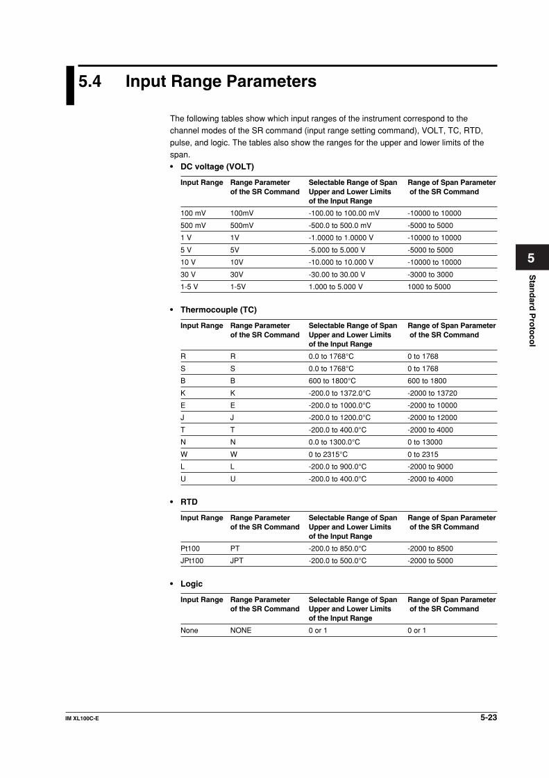
5-23IM XL100C-E
1
2
3
4
5
6
7
App
Index
Stan
dard
Pro
toco
l
5.4 Input Range Parameters
The following tables show which input ranges of the instrument correspond to thechannel modes of the SR command (input range setting command), VOLT, TC, RTD,
pulse, and logic. The tables also show the ranges for the upper and lower limits of thespan.• DC voltage (VOLT)
Input Range Range Parameter Selectable Range of Span Range of Span Parameterof the SR Command Upper and Lower Limits of the SR Command
of the Input Range
100 mV 100mV -100.00 to 100.00 mV -10000 to 10000
500 mV 500mV -500.0 to 500.0 mV -5000 to 5000
1 V 1V -1.0000 to 1.0000 V -10000 to 10000
5 V 5V -5.000 to 5.000 V -5000 to 5000
10 V 10V -10.000 to 10.000 V -10000 to 10000
30 V 30V -30.00 to 30.00 V -3000 to 3000
1-5 V 1-5V 1.000 to 5.000 V 1000 to 5000
• Thermocouple (TC)
Input Range Range Parameter Selectable Range of Span Range of Span Parameterof the SR Command Upper and Lower Limits of the SR Command
of the Input Range
R R 0.0 to 1768°C 0 to 1768
S S 0.0 to 1768°C 0 to 1768
B B 600 to 1800°C 600 to 1800
K K -200.0 to 1372.0°C -2000 to 13720
E E -200.0 to 1000.0°C -2000 to 10000
J J -200.0 to 1200.0°C -2000 to 12000
T T -200.0 to 400.0°C -2000 to 4000
N N 0.0 to 1300.0°C 0 to 13000
W W 0 to 2315°C 0 to 2315
L L -200.0 to 900.0°C -2000 to 9000
U U -200.0 to 400.0°C -2000 to 4000
• RTD
Input Range Range Parameter Selectable Range of Span Range of Span Parameterof the SR Command Upper and Lower Limits of the SR Command
of the Input Range
Pt100 PT -200.0 to 850.0°C -2000 to 8500
JPt100 JPT -200.0 to 500.0°C -2000 to 5000
• Logic
Input Range Range Parameter Selectable Range of Span Range of Span Parameterof the SR Command Upper and Lower Limits of the SR Command
of the Input Range
None NONE 0 or 1 0 or 1
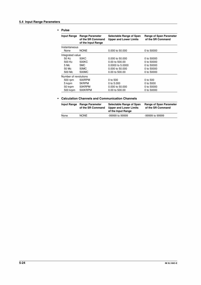
5-24 IM XL100C-E
• Pulse
Input Range Range Parameter Selectable Range of Span Range of Span Parameterof the SR Command Upper and Lower Limits of the SR Commandof the Input Range
InstantaneousNone NONE 0.000 to 50.000 0 to 50000
Integrated value50 Kc 50KC 0.000 to 50.000 0 to 50000500 Kc 500KC 0.00 to 500.00 0 to 500005 Mc 5MC 0.0000 to 5.0000 0 to 5000050 Mc 50MC 0.000 to 50.000 0 to 50000500 Mc 500MC 0.00 to 500.00 0 to 50000
Number of revolutions500 rpm 500RPM 0 to 500 0 to 5005 krpm 5KRPM 0 to 5.000 0 to 500050 krpm 50KRPM 0.000 to 50.000 0 to 50000500 krpm 500KRPM 0.00 to 500.00 0 to 50000
• Calculation Channels and Communication Channels
Input Range Range Parameter Selectable Range of Span Range of Span Parameterof the SR Command Upper and Lower Limits of the SR Command
of the Input Range
None NONE -99999 to 99999 -99999 to 99999
5.4 Input Range Parameters

5-25IM XL100C-E
1
2
3
4
5
6
7
App
Index
Stan
dard
Pro
toco
l
5.5 Setting Commands (Setting)
SR Sets the input rangeWhen setting the channel to skipSyntax SR p1,p2<terminator>
p1 Channel number
Analog CH 8-CH input: 01 to 08
16-CH input: 01 to 16
Pulse CH PL01
Logic CH DI01, DI02
Calc. CH CA01 to CA32
Comm. CH CO01 to CO32
p2 Channel mode SKIP
Query SR[ p1]?
Example Set channel 01 to OFF (SKIP).
SR 01,SKIP
Description • This command cannot be specified while
logging is in progress.
• Measurements are not made on channels that
are set to OFF.
When setting the channel to voltage,thermocouple, RTD, pulse input, calculationchannel, or communication channel withoutscalingSyntax SR p1,p2,p3,p4,p5<terminator>
p1 Channel number
Analog CH 8-CH input: 01 to 08
16-CH input: 01 to 16
Pulse CH PL01
Logic CH DI01, DI02
Calc. CH CA01 to CA32
Comm. CH CO01 to CO32
p2 Input type
DC voltage: VOLT
Thermocouple: TC
RTD: RTD
None: NONE
p3 Input Range
p4 Span lower limit
p5 Span upper limit
Query SR[ p1]?
Example Set the input type for channel 01 to TC type R,
span lower limit to 0°C, and span upper limit to
1760.0°C.
SR 01,TC,R,0,17600
Description • Only span parameters p4 and p5 can be
specified while logging is in progress.
• Set parameters p3, p4, and p5 according to
the tables in section 5.4, “Input Range
Parameters.”
• For parameters p4 and p6, enter a value using
5 digits or less excluding the decimal point.
The decimal position is fixed to the position
indicated in the tables in section 5.4, “Input
Range Parameters.”
• Select “None” for parameter p2 for pulse CH,
logic CH, calculation CH, and communication
CH.
When calculating the difference between channels(no scaling)Syntax SR p1,p2,p3,p4,p5,p6,p7<terminator>
p1 Channel number
Analog CH 8-CH input: 01 to 08
16-CH input: 01 to 16
Calc. CH CA01 to CA32
Comm. CH CO01 to CO32
p2 Setting type DELTA
p3 Input type
DC voltage: VOLT
Thermocouple: TC
RTD: RTD
None: NONE
p4 Input Range
p5 Span lower limit
p6 Span upper limit
p7 Reference channel
Analog CH 8-CH input: 01 to 08
16-CH input: 01 to 16
Calc. CH CA01 to CA32
Comm. CH CO01 to CO32
Constant –9.9999E+29 to
1.0000E – 30,0,1.0000E
– 30 to 9.9999E+29
Query SR[ p1]?
Example Set the channel 10 setting type to differential
calculation with respect to channel 01 (reference
channel), the input type to TC, the input range to
R, the span lower limit to 10.0°C, and the span
lower limit to 100.0°C.
SR 10,DELTA,TC,R,100,1000,01
Description • Only span parameters p5 and p6 can be
specified while logging is in progress.
• Set parameters p4, p5, and p6 according to
the tables section 5.4, “Input Range
Parameters.”
• For parameters p5 and p6, enter a value
using 5 digits or less excluding the decimal
point. The decimal position is fixed to the
position indicated in the tables in section 5.4,
“Input Range Parameters.”
When setting the channel to voltage,thermocouple, RTD, pulse input, calculationchannel, or communication channel with scaling
5.5 Setting Commands (Setting)

5-26 IM XL100C-E
Syntax SR p1,p2,p3,p4,p5,p6,p7,p8,p9,
p10<terminator>
p1 Channel number
Analog CH 8-CH input: 01 to 08
16-CH input: 01 to 16
Pulse CH PL01
Logic CH DI01, DI02
Calc. CH CA01 to CA32
Comm. CH CO01 to CO32
p2 Setting type SCALE
p3 Input type
DC voltage: VOLT
Thermocouple: TC
RTD: RTD
None: NONE
p4 Input range
p5 Span lower limit
p6 Span upper limit
p7 CH other than communication CH
Scaling lower limit: -30000 to 30000
Comm. CH
Span decimal place
x.xxxx: 0
xx.xxx: 1
xxx.xx: 2
xxxx.x: 3
xxxxx: 4
p8 CH other than communication CH
Scaling lower limit: -30000 to 30000
Comm. CH
Scaling factor: -99999 to 99999
p9 Scaling decimal place
x.xxxx: 0
xx.xxx: 1
xxx.xx: 2
xxxx.x: 3
xxxxx: 4
p10 Unit (up to 6 characters)
Query SR[ p1]?
Example Convert the DC voltage measured on channel 02
to DC current. Set the input range to 6 V, the
span lower limit to 1 V, the span upper limit to 5
V, the scale lower limit to 1.00 A, and the scale
upper limit to 5.00 A.
SR 02,SCALE,VOLT,6V,1000,5000,100,
500,2,A
Description • Only span parameters p5 and p6 can be
specified while logging is in progress.
• Set parameters p4, p5, and p6 according to
the tables in section 5.4, “Input Range
Parameters.”
• For parameters p5 and p6, enter a value using
5 digits or less excluding the decimal point.
The decimal position is fixed to the position
indicated in the tables in section 5.4, “Input
Range Parameters.”
• For parameters p7, p8, and p9, either set all
three parameters or omit all three parameters
when the channel is not set to communication
channel.
SO Sets the calculating equationSyntax SO p1,p2,p3,p4,p5,p6,p7<terminator>
p1 Calculation channel number CA01 to CA32
31 to 42(*)
p2 Calculation ON/OFF ON, OFF
p3 Calculating equation (up to 40 characters,
differential calculation only)
p4 Span lower limit -9999999 to 99999999
p5 Span upper limit -9999999 to 99999999
p6 Span decimal place
x.xxxx: 0
xx.xxx: 1
xxx.xx: 2
xxxx.x: 3
xxxxx: 4
p7 Unit (up to 6 characters)
Query SO[ p1]?
Example Set the calculation channel to 31, the calculation
to ON, the calculating equation to “the sum of
channel 01 and 02”, the span lower limit to –
10.0000, the span upper limit to 15.0000, and the
unit to V.
SO 31,ON,01+02,-100000,150000,4,V
Description • Only span parameters p4 and p5 can be
specified while logging is in progress.
• For parameters p4 and p5, enter a value
using 7 digits or less ,excluding the decimal,
for negative numbers and 8 digits or less for
positive numbers.
• For parameters p4, p5, and p6, either set all
three parameters or omit all three parameters.
• Setting parameter p1 to 31 to 42 is equivalent
to specifying CA21 to CA32.
• The parameters that can be used in the
equation of p3 are as follows.
8-CH input: CH01 to CH08
16- CH input: CH01 to CH16
Calc. CH: CA01 to CA32
Comm. CH: CO01 to CO32
Constant: –9.9999E+29 to – 1.0000E
–30,
0,
1.0000E–30 to 9.9999E+
29
5.5 Setting Commands (Setting)

5-27IM XL100C-E
1
2
3
4
5
6
7
App
Index
Stan
dard
Pro
toco
l
SA Sets the alarmWhen not using the alarmSyntax SA p1,p2,p3<terminator>
p1 Channel number
Analog CH 8-CH input: 01 to 08
16-CH input: 01 to 16
Pulse CH PL01
Logic CH DI01, DI02
Calc. CH CA01 to CA32
Comm. CH CO01 to CO32
p2 Alarm number1
p3 Alarm ON/OFF OFF
Query SA[ p1[,p2]]?
Example Turn OFF alarm number 1 of channel 10.
SA 10,1,OFF
Description This command cannot be issued while logging is
in progress.
When using the alarmSyntax SA p1,p2,p3,p4,p5,p6,p7<terminator>
p1 Channel number
Analog CH 8-CH input: 01 to 08
16-CH input: 01 to 16
Pulse CH PL01
Logic CH DI01, DI02
Calc. CH CA01 to CA32
Comm. CH CO01 to CO32
p2 Alarm number1
p3 Alarm ON/OFF ON
p4 Alarm type
High limit alarm: H
Low limit alarm: L
Window IN: I
Window OUT: O
Reserved h, l, R, r, T, and t
(Characters are case-sensitive.)
p5 Alarm value1
p6 Relay setting
Relay ON: ON
Relay OFF: OFF
p7 Alarm output number 101 to 104
p8 Alarm value 2
Query SA[ p1[,p2]]?
Example Set a high limit alarm (alarm value = 1000) in
alarm number 1 of channel 02, and activate relay
number 1 when an alarm occurs.
SA 02,1,ON,H,1000,ON,I01
Description • This command cannot be issued while logging
is in progress.
• When the input range setting (SR command)
is set to OFF, p3 cannot be turned ON.
• All alarm settings are turned OFF for the
following cases.
• When the input type is changed (VOLT,
TC, etc).
• When the input range is changed.
• When the span and scaling values are
changed during scaling display (includes
changing the decimal position).
• When the calculating equation is changed
or the span value is changed for a
calculation channel (CA01 to CA32).
• For the range of alarm values of p5, see the
tables in section 5.4, “Input Range
Parameters.”
• Set the alarm value of a calculation channel
(CA01 to CA32) within the range of the span.
• For the alarm values of p5 and p6, enter a
value using 5 digits or less, excluding the
decimal. For calculation channels (CA01 to
CA32), enter a value using 5 digits or less,
excluding the decimal.
SD Sets the data and timeSyntax SD p1,p2<terminator>
p1 Date (YY/MM/DD fixed form)
YY (year): 00 to 99
MM (month): 01 to 12
DD (day): 01 to 31
p2 Time (HH/MM/SS fixed form)
HH (hour): 00 to 23
MM (min): 00 to 59
SS (s): 00 to 59
Query SD?
Example Set the internal clock to 13:00:00, October 1,
2005.
SD 05/10/01,13:00:00
Description • The form of p1 and p2 is fixed to 8 characters.
Use the following form. Do not enter spaces
between the digits; otherwise an error will
occur.
p1 = YY/MM/DD (Lower two digits of the year/
month/day)
p2 = HH:MM:SS (Hour:minute:second)
• This command cannot be issued while logging
is in progress.
SW Sets the sampling intervalSyntax SW p1,p2<terminator>
p1 Sampling Interval
For 8 ch input:
100ms, 200ms, 500ms, 1s, 2s, 5s,
10s, 20s, 30s, 1min, 2min, 5min,
10min, 20min, 30min, 60min, or 1h
For 16 ch input:
200ms, 500ms, 1s, 2s, 5s, 10s,
20s, 30s, 1min, 2min, 5min,
10min, 20min, 30min, 60min, or 1h
p2 Reserved
Query SW?
Example Sets the sampling interval to 10 s.
SW 10S
5.5 Setting Commands (Setting)
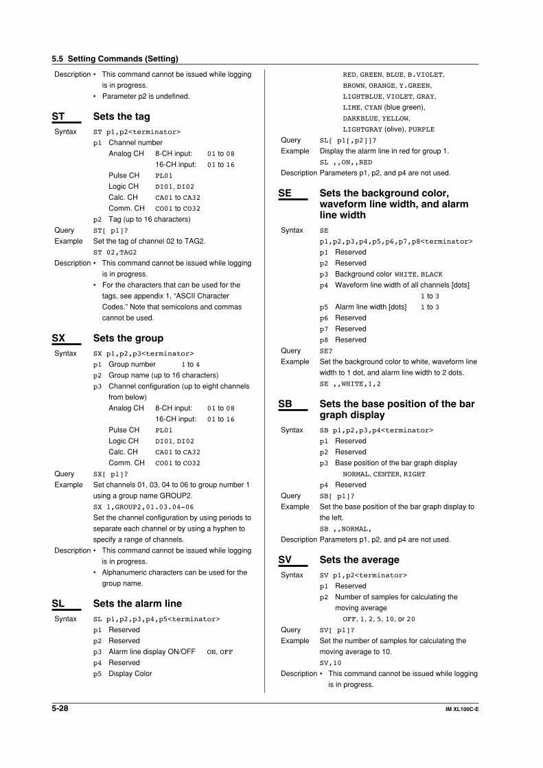
5-28 IM XL100C-E
Description • This command cannot be issued while logging
is in progress.
• Parameter p2 is undefined.
ST Sets the tagSyntax ST p1,p2<terminator>
p1 Channel number
Analog CH 8-CH input: 01 to 08
16-CH input: 01 to 16
Pulse CH PL01
Logic CH DI01, DI02
Calc. CH CA01 to CA32
Comm. CH CO01 to CO32
p2 Tag (up to 16 characters)
Query ST[ p1]?
Example Set the tag of channel 02 to TAG2.
ST 02,TAG2
Description • This command cannot be issued while logging
is in progress.
• For the characters that can be used for the
tags, see appendix 1, “ASCII Character
Codes.” Note that semicolons and commas
cannot be used.
SX Sets the groupSyntax SX p1,p2,p3<terminator>
p1 Group number 1 to 4
p2 Group name (up to 16 characters)
p3 Channel configuration (up to eight channels
from below)
Analog CH 8-CH input: 01 to 08
16-CH input: 01 to 16
Pulse CH PL01
Logic CH DI01, DI02
Calc. CH CA01 to CA32
Comm. CH CO01 to CO32
Query SX[ p1]?
Example Set channels 01, 03, 04 to 06 to group number 1
using a group name GROUP2.
SX 1,GROUP2,01.03.04-06
Set the channel configuration by using periods to
separate each channel or by using a hyphen to
specify a range of channels.
Description • This command cannot be issued while logging
is in progress.
• Alphanumeric characters can be used for the
group name.
SL Sets the alarm lineSyntax SL p1,p2,p3,p4,p5<terminator>
p1 Reserved
p2 Reserved
p3 Alarm line display ON/OFF ON, OFF
p4 Reserved
p5 Display Color
RED, GREEN, BLUE, B.VIOLET,
BROWN, ORANGE, Y.GREEN,
LIGHTBLUE, VIOLET, GRAY,
LIME, CYAN (blue green),
DARKBLUE, YELLOW,
LIGHTGRAY (olive), PURPLE
Query SL[ p1[,p2]]?
Example Display the alarm line in red for group 1.
SL ,,ON,,RED
Description Parameters p1, p2, and p4 are not used.
SE Sets the background color,waveform line width, and alarmline width
Syntax SE
p1,p2,p3,p4,p5,p6,p7,p8<terminator>
p1 Reserved
p2 Reserved
p3 Background color WHITE, BLACK
p4 Waveform line width of all channels [dots]
1 to 3
p5 Alarm line width [dots] 1 to 3
p6 Reserved
p7 Reserved
p8 Reserved
Query SE?
Example Set the background color to white, waveform line
width to 1 dot, and alarm line width to 2 dots.
SE ,,WHITE,1,2
SB Sets the base position of the bargraph display
Syntax SB p1,p2,p3,p4<terminator>
p1 Reserved
p2 Reserved
p3 Base position of the bar graph display
NORMAL, CENTER, RIGHT
p4 Reserved
Query SB[ p1]?
Example Set the base position of the bar graph display to
the left.
SB ,,NORMAL,
Description Parameters p1, p2, and p4 are not used.
SV Sets the averageSyntax SV p1,p2<terminator>
p1 Reserved
p2 Number of samples for calculating the
moving average
OFF, 1, 2, 5, 10, or 20
Query SV[ p1]?
Example Set the number of samples for calculating the
moving average to 10.
SV,10
Description • This command cannot be issued while logging
is in progress.
5.5 Setting Commands (Setting)
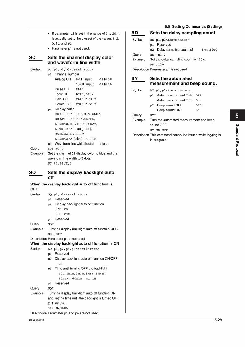
5-29IM XL100C-E
1
2
3
4
5
6
7
App
Index
Stan
dard
Pro
toco
l
• If parameter p2 is set in the range of 2 to 20, it
is actually set to the closest of the values 1, 2,
5, 10, and 20.
• Parameter p1 is not used.
SC Sets the channel display colorand waveform line width
Syntax SC p1,p2,p3<terminator>
p1 Channel number
Analog CH 8-CH input: 01 to 08
16-CH input: 01 to 16
Pulse CH PL01
Logic CH DI01, DI02
Calc. CH CA01 to CA32
Comm. CH CO01 to CO32
p2 Display color
RED, GREEN, BLUE, B.VIOLET,
BROWN, ORANGE, Y.GREEN,
LIGHTBLUE, VIOLET, GRAY,
LIME, CYAN (blue green),
DARKBLUE, YELLOW,
LIGHTGRAY (olive), PURPLE
p3 Waveform line width [dots] 1 to 3
Query SC[ p1]?
Example Set the channel 02 display color to blue and the
waveform line width to 3 dots.
SC 02,BLUE,3
SQ Sets the display backlight autooff
When the display backlight auto off function isOFFSyntax SQ p1,p2<terminator>
p1 Reserved
p2 Display backlight auto off function
ON: ON
OFF: OFF
p3 Reserved
Query SQ?
Example Turn the display backlight auto off function OFF.
SQ ,OFF
Description Parameter p1 is not used.
When the display backlight auto off function is ONSyntax SQ p1,p2,p3,p4<terminator>
p1 Reserved
p2 Display backlight auto off function ON/OFF
ON
p3 Time until turning OFF the backlight
10S, 1MIN, 2MIN, 5MIN, 10MIN,
30MIN, 60MIN, or 1H
p4 Reserved
Query SQ?
Example Turn the display backlight auto off function ON
and set the time until the backlight is turned OFF
to 1 minute.
SQ ,ON,1MIN
Description Parameter p1 and p4 are not used.
BD Sets the delay sampling countSyntax BD p1,p2<terminator>
p1 Reserved
p2 Delay sampling count [s] 1 to 3600
Query BD[ p1]?
Example Set the delay sampling count to 120 s.
BD ,120
Description Parameter p1 is not used.
BY Sets the automatedmeasurement and beep sound.
Syntax BY p1,p2<terminator>
p1 Auto measurement OFF: OFF
Auto measurement ON: ON
p2 Beep sound OFF: OFF
Beep sound ON: ON
Query BY?
Example Turn the automated measurement and beep
sound OFF.
BY ON,OFF
Description This command cannot be issued while logging is
in progress.
5.5 Setting Commands (Setting)

5-30 IM XL100C-E
5.6 Setting Commands (Control)
UD Switches the displayWhen switching the display back to the displaythat existed before settings were changed usingcommunication commandsSyntax UD p1<terminator>
p1 Display switching 0
Example Switch the display back to the display that
existed before settings were changed using
communication commands.
UD 0
When switching the display using communicationcommandsSyntax UD p1,p2,p3<terminator>
p1 Display switching 1
p2 Display item
Waveform & digital display: TREND
Digital display: DIGITAL
Bar graph display: BAR
Alarm summary display: ALARM
Review display: REVIEW
Reserved: OVERVIEW
p3 Group number 1 to 4
Example Set the display to waveform & digital, and set the
number of the group to be displayed to 4.
UD 1,TREND,4
PS Starts/Stops loggingSyntax PS p1<terminator>
p1 Logging start/stop
Start: 0
Stop: 1
Example Start logging.
PS 0
Description If the logging start trigger is set to manual and
logging does not start immediately, the GS610
enters logging standby until the trigger condition
is met.
AK Acknowledges the alarm status(alarm acknowledge)
Syntax AK p1<terminator>
p1 Execute alarm acknowledge 0
Example Confirm the current hold condition of the alarm
(execute alarm acknowledge).
AK 0
EV Saves manual sampled data andscreen image data to the externalstorage medium
Syntax EV p1<terminator>
p1 Operation type
Saves manual sampled data to the external
storage medium: 0
Saves screen image data to the external storage
medium: 2
Reserved: 1, 3, 4
Example Save manual sampled data to the external
storage medium.
EV 1
Description • Data cannot be saved while logging.
• Parameter p1 cannot be set to 0 while the
external storage medium is being formatted or
while data is being saved to the external
storage medium.
LO Loads the setup dataSyntax LO p1<terminator>
p1 File name (up to 8 characters)
Example Load the setting data of setting commands from
the setup file SETFILE1 (.pnl extension).
LO SETFILE1
Description • This command is the same as the YO
command. To apply the functions of the basic
setting commands, the settings must be
saved using the XE command.
• This command can be issued only when the
external storage medium is specified and the
external storage medium is inserted.
LI Saves the setting dataSyntax LI p1<terminator>
p1 File name (up to 8 characters)
Example Save the setting data of both setting and basic
setting commands to the file SETFILE2.
LI SETFILE2
Description • A “.set” extension is attached to the saved file.
This command is equivalent to the YI
command.
• The settings are not saved with this command
if an external storage media error occurs such
as the external storage medium not inserted
at the save destination.
CM Sets the communication inputdata
Syntax CM p1,p2<terminator>
p1 Communication input data number
C01 to C32 (same as CO01 to CO32)
CO01 to CO32
p2 Communication input data
Selectable range: -9.9999E+29 to -
1.0000E- 30, 0,
1.0000E-30 to
-9.9999E+29
(The + sign of “E+” can
be omitted.)
Query CM?
5.6 Setting Commands (Control)

5-31IM XL100C-E
1
2
3
4
5
6
7
App
Index
Stan
dard
Pro
toco
l
Example Set 1.0000E-10 to communication input data
number CO01.
CM CO01,1.0000E-10
EM Starts/stops the e-mailtransmission function
Syntax M p1<terminator>
p1 Operation type
Start: 0
Stop: 1
Example Start the e-mail transmission function.
EM 0
Description To use the e-mail transmission function, you
must set the Ethernet interface, e-mail address,
and contents to be transmitted. For the
procedure to set each item, see section 2.11
“Setting the E-mail Transmission function”.
KE Key operation commandSyntax KE p1<terminator>
p1 Key type
ESC key: ESC
HOME key: HOME
REVIEW key: REVIEW
FILE key: FILE
SETTING key: SETTING
HOLD key: HOLD
TIME/DIV left key: TIMEDIVSHORT
TIME/DIV right key: TIMEDIVLONG
RANGE key: RANGE
SAVE key: SAVE
DISPLAY key: DISP
GROUP key: GROUP
MARK key: MARK
MARK left key: MARKLEFT
MARK right key: MARKRIGHT
SET key: SET
START/STOP key: STARTSTOP
HOLD key: HOLD
Up arrow key: UP
Down arrow key: DOWN
Right arrow key: RIGHT
Left arrow key: LEFT
SELECT key: SELECT
Example Press the DISPLAY key.
KE DISP
Description Operates in the same fashion as the key
operation on the XL100. For consecutive key
operations, transmit the commands in the same
order as the key operation on the XL100.
5.7 Basic Setting Commands
• In order to activate the settings that are changed
using the basic setting commands, the settingsmust be saved using the XE command.The settings that are returned in response to a
query after issuing a basic setting command are thenew settings even if the settings have not beensaved with the XE command. However, the new
settings only take effect after saving the settingsusing the XE command.If you discard the settings with the XE command or
start the logging operation before saving thesettings with the XE command, the settings that arereturned in response to a query are reset to those
before the change.• Basic setting commands cannot be used to change
settings while logging is in progress.
XA Sets the alarmSyntax XA
p1,p2,p3,p4,p5,p6,p7,p8,p9<terminator>
p1 Reserved
p2 Output number to be set to AND
For all ORs: NONE
Independent setting: I01, I02, I03, or
I04
Range setting: Ixx-Ixy
(Ixx,Ixy: I01 to I04)
p3 Reserved
p4 Output hold/non-hold
Hold: HOLD
Non-hold: NONHOLD
p5 Hold/Not hold the alarm status display
Hold: HOLD
Non-hold: NONHOLD
p6 Reserved
p7 Reserved
p8Alarm hysteresis ON/OFF: ON or OFF
p9Alarm buzzer ON/OFF: ON, OFF
Query XA?
Example Set output numbers I01 to I04 to AND, hold the
output, hold the alarm status display, turn the
alarm hysteresis ON, and turn the alarm buzzer
ON.
XA ,I01-I12,HOLD,HOLD,,,ON,ON
Description Parameters p1, p3, p6, and p7 are not used.
XB Burnout setting (query only)Syntax XB p1,p2<terminator>
p1 Reserved (NULL)
p2 Burnout procedure UP
5.7 Basic Setting Commands
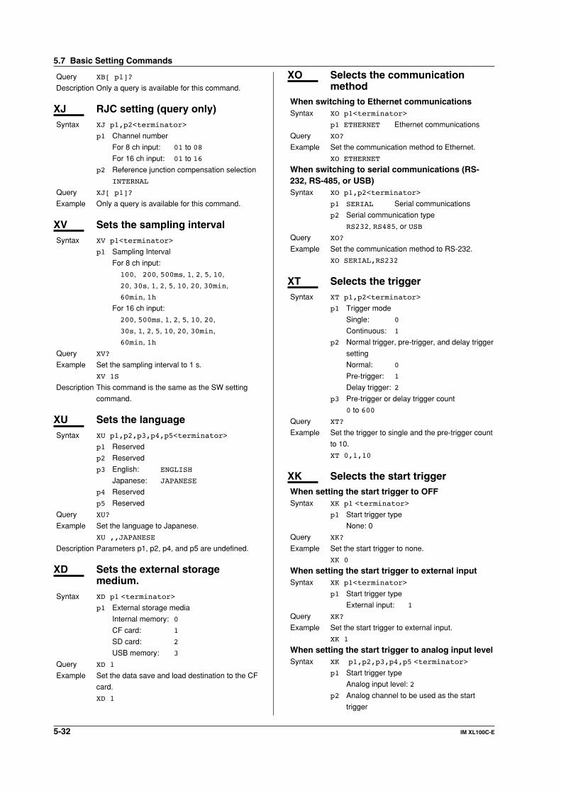
5-32 IM XL100C-E
Query XB[ p1]?
Description Only a query is available for this command.
XJ RJC setting (query only)Syntax XJ p1,p2<terminator>
p1 Channel number
For 8 ch input: 01 to 08
For 16 ch input: 01 to 16
p2 Reference junction compensation selection
INTERNAL
Query XJ[ p1]?
Example Only a query is available for this command.
XV Sets the sampling intervalSyntax XV p1<terminator>
p1 Sampling Interval
For 8 ch input:
100, 200, 500ms, 1, 2, 5, 10,
20, 30s, 1, 2, 5, 10, 20, 30min,
60min, 1h
For 16 ch input:
200, 500ms, 1, 2, 5, 10, 20,
30s, 1, 2, 5, 10, 20, 30min,
60min, 1h
Query XV?
Example Set the sampling interval to 1 s.
XV 1S
Description This command is the same as the SW setting
command.
XU Sets the languageSyntax XU p1,p2,p3,p4,p5<terminator>
p1 Reserved
p2 Reserved
p3 English: ENGLISH
Japanese: JAPANESE
p4 Reserved
p5 Reserved
Query XU?
Example Set the language to Japanese.
XU ,,JAPANESE
Description Parameters p1, p2, p4, and p5 are undefined.
XD Sets the external storagemedium.
Syntax XD p1 <terminator>
p1 External storage media
Internal memory: 0
CF card: 1
SD card: 2
USB memory: 3
Query XD 1
Example Set the data save and load destination to the CF
card.
XD 1
XO Selects the communicationmethod
When switching to Ethernet communicationsSyntax XO p1<terminator>
p1 ETHERNET Ethernet communications
Query XO?
Example Set the communication method to Ethernet.
XO ETHERNET
When switching to serial communications (RS-232, RS-485, or USB)Syntax XO p1,p2<terminator>
p1 SERIAL Serial communications
p2 Serial communication type
RS232, RS485, or USB
Query XO?
Example Set the communication method to RS-232.
XO SERIAL,RS232
XT Selects the triggerSyntax XT p1,p2<terminator>
p1 Trigger mode
Single: 0
Continuous: 1
p2 Normal trigger, pre-trigger, and delay trigger
setting
Normal: 0
Pre-trigger: 1
Delay trigger: 2
p3 Pre-trigger or delay trigger count
0 to 600
Query XT?
Example Set the trigger to single and the pre-trigger count
to 10.
XT 0,1,10
XK Selects the start triggerWhen setting the start trigger to OFFSyntax XK p1 <terminator>
p1 Start trigger type
None: 0
Query XK?
Example Set the start trigger to none.
XK 0
When setting the start trigger to external inputSyntax XK p1<terminator>
p1 Start trigger type
External input: 1
Query XK?
Example Set the start trigger to external input.
XK 1
When setting the start trigger to analog input levelSyntax XK p1,p2,p3,p4,p5 <terminator>
p1 Start trigger type
Analog input level: 2
p2 Analog channel to be used as the start
trigger
5.7 Basic Setting Commands

5-33IM XL100C-E
1
2
3
4
5
6
7
App
Index
Stan
dard
Pro
toco
l
For 8 ch input: 01 to 08
For 16 ch input: 01 to 16
p3 Start trigger level type
High limit trigger: H
Low limit trigger: L
Window IN: I
Window OUT: O
p4 High limit value -99999 to 99999
p5 Low limit value -99999 to 99999
Query XK?
Example Set the start trigger to Window IN of analog input
CH3, and set the high and low limits to 2000 and
1000, respectively.
XK 2,03,I,2000,1000
Description Set the high and low limits using a five-digit
integer without a decimal point. The decimal
place is the same as the span and scale settings
of the analog input channel.
Be sure to set the high limit greater than or equal
to the low limit.
When setting the start trigger to an alarmSyntax XT p1,p2<terminator>
p1 Start trigger type
Alarm: 3
p2 Alarm output number to be used as the start
trigger
1 to 4
Query XK?
Example Set the start trigger to alarm output number 4.
XK 3,4
When setting the start trigger to a specific timeSyntax XK p1,p2,p3
p1Start trigger type
Time: 4
p2 Start date (YY/MM/DD fixed form)
YY (year): 00 to 99
MM (month): 01 to 12
DD (day): 01 to 31
p3Start time (HH/MM/SS fixed form)
HH (hour): 00 to 23
MM (min): 00 to 59
SS (s): 00 to 59
Query XK?
Example Set the start trigger to 3:45:6 on January 2, 2006.
XK 4,06/01/02,03:45:06
XL Selects the end triggerWhen setting the end trigger to OFFSyntax XL p1<terminator>
p1 End trigger type
None:0
Query XL?
Example Set the end trigger to none.
XL 0
When setting the end trigger to external inputSyntax XL p1<terminator>
p1 End trigger type
External input: 1
Query XL?
Example Set the end trigger to external input.
XL 1
When setting the end trigger to analog input levelSyntax XLp1,p2,p3,p4,p5<terminator>
p1 End trigger type
Analog input level: 2
p2 Analog channel to be used as the end
trigger
For 8 ch input: 01 to 08
For 16 ch input: 01 to 16
p3 End trigger level type
High limit trigger: H
Low limit trigger: L
Window IN: I
Window OUT :O
p4 High limit value -99999 to 99999
p5 Low limit value -99999 to 99999
Query XL?
Example Set the end trigger to low limit 500 of analog
input CH3.
XL 2,03,L,500
Description Set the high and low limits using a five-digit
integer without a decimal point. The decimal
place is the same as the span and scale settings
of the analog input channel.
Be sure to set the high limit greater than or equal
to the low limit.
When setting the end trigger to an alarmSyntax XL p1,p2
p1 End trigger type
Alarm: 3
p2 Alarm output number to be used as the end
trigger
1 to 4
Query XL?
Example Set the end trigger to alarm output number 1.
XL 3,1
When setting the end trigger to a specific timeSyntax XL p1,p2,p3
p1 End trigger type
Time: 4
p2 End date (YY/MM/DD fixed form)
YY (year): 00 to 99
MM (month): 01 to 12
DD (day): 01 to 31
p3 End time (HH/MM/SS fixed form)
HH (hour): 00 to 23
MM (min): 00 to 59
SS (s): 00 to 59
Query XK?
Example Set the end trigger to 4:56:7 on February 3,
2030.
XL 4,30:02:03,04:56:07
When setting the end trigger to a timerSyntax XL p1,p2
5.7 Basic Setting Commands

5-34 IM XL100C-E
p1 End trigger type
Timer: 5
p2 End timer (s)
1 to 31622400
Query XL?
Example Set the end trigger to a 600-s timer.
XL 5,600
XH Sets the key login and autologout functions
Syntax XH p1,p2,p3<terminator>
p1 Key login function
Enable: USE
Disable: NOT
p2 Timeout function
Enable: USE
Disable: NOT
p3 Reserved
Query XH?
Example Enable the key login and auto logout functions.
XH USE,ON,
Description Parameter p3 is not used.
XE Sets whether to save or discardthe settings specified by a basicsetting command
Syntax XE p1<terminator>
p1 Save or discard settings
Save: STORE
Discard: ABORT
Example Save the settings of the basic setting command.
XE STORE
Description In order to activate the settings that are changed
using the basic setting commands, the settings
must be saved using the XE command. If you do
not, the settings before the change are activated
if logging is started.
XG Sets the time zoneSyntax XG p1<terminator>
p1Offset time from the Greenwich Mean Time
-1200 to 1200
Upper two digits (hour): 00 to 12
Lower two digits (minutes): Fixed to 00
Example Set the offset time from the GMT to 9 hours
ahead.
XG 0900
XY Sets the statistical calculationSyntax XY p1,p2,p3,p4,p5<terminator>
p1 Calculation of the maximum value
Enable: ON
Disable: OFF
p2 Calculation of the minimum value
Enable: ON
Disable: OFF
p3 Calculation of the average value
Enable: ON
Disable: OFF
p4 Calculation of the peak (P-P) value
Enable: ON
Disable: OFF
p5 Calculation of the rms value
Enable: ON
Disable: OFF
Query XY?
YA Sets the IP address, subnetmask, and default gateway
Syntax YA p1,p2,p3<terminator>
p1 IP address
0.0.0.0 to 255.255.255.255
p2 Subnet mask
0.0.0.0 to 255.255.255.255
p3 Default gateway
0.0.0.0 to 255.255.255.255
Query YA?
Example Set the IP address to 192.168.111.24, the subnet
mask to 255.255.255.0, and the default gateway
to 0.0.0.0.
YA 192.168.111.24,255.255.255.0,
0.0.0.0
Description The settings changed with this command are
applied when they are saved using the XE
command.
YB Queries the IPV6 informationSyntax YB p1,p2,p3<terminator>
p1 Default Gateway
OFF,xxxx::xxxx::xxxx::xxxx%6
p2 Global
OFF,xxxx::xxxx::xxxx::xxxx%6
p3 Site-local
OFF,xxxx::xxxx::xxxx::xxxx%4
p4 Link local
OFF,xxxx::xxxx::xxxx::xxxx%4
p5 6to4
OFF,xxxx::xxxx::xxxx::xxxx%6
p6 Automatic tunnel 1
OFF,xxxx::xxxx::xxxx::xxxx%6
p7 Automatic tunnel 2
OFF,xxxx::xxxx::xxxx::xxxx%6
p8 Automatic tunnel 3
OFF,xxxx::xxxx::xxxx::xxxx%6
Query YB?
YK Sets the keepaliveSyntax YK p1<terminator>
p1 Enable/Disable keepalive
Enable: ON
Disable: OFF
Query YK?
5.7 Basic Setting Commands

5-35IM XL100C-E
1
2
3
4
5
6
7
App
Index
Stan
dard
Pro
toco
l
Example Disable keepalive.
YK OFF
Description The setting changed with this
command is applied when it is saved using the
XE command.
YN Sets the DNSWhen not using the DNSSyntax YNp1<terminator>
p1 Disable DNS OFF
Query YN?
Example Do not use the DNS.
YN OFF
Description The setting changed with this command is
applied when it is saved using the XE command.
When using the DNSSyntax YN p1,p2,p3,p4,p5,p6,p7<terminator>
p1 Enable DNS ON
p2 Address of the primary DNS server
0.0.0.0 to 255.255.255.255
p3 Address of the secondary DNS server
0.0.0.0 to 255.255.255.255
p4 Host name (up to 64 characters)
p5 Domain name (up to 64 characters)
p6 Domain suffix 1 (up to 64 characters)
p7 Domain suffix 2 (up to 64 characters)
Query YN?
Example Use the DNS server at 192.168.0.1.
YN ON,192.168.0.1
Description The settings changed with this command are
applied when they are saved using the XE
command.
YE Sets the SNTP (timesynchronization function)
When not using the SNTPSyntax YE p1<terminator>
p1 Disable 0
Query YE?
Example Disable SNTP.
YE 0
When using the SNTPSyntax YE p1,p2,p3<terminator>
p1 Enable 1
p2 Server name (up to 64 alphanumeric
characters)
p3 Confirmation time interval (hh) 1 to 24
Query YE?
Example Use the SNTP server named MCC at six-hour
intervals.
YE 1,MCC,6
YQ Sets the Ethernetcommunication timeout
When not using the timeoutSyntax YQ p1<terminator>
p1 Enable/Disable communication timeout
Enable: ON
Disable: OFF
Query YQ?
Example Disable timeout.
YQ OFF
Description The setting changed with this command is
applied when it is saved using the XE command.
When using the timeoutSyntax YQ p1,p2<terminator>
p1 Enable/Disable communication timeout
Enable: ON
Disable: OFF
p2 Timeout value (min) 1 to 120
Query YQ?
Example Enable the communication timeout and set the
timeout period to 3 min.
YQ ON,3
Description The settings changed with this command are
applied when they are saved using the XE
command.
YS Sets the serial interfaceSyntax YS p1,p2,p3,p4,p5,p6,p7<terminator>
p1 Baud rate [bps]
1200, 2400, 4800, 9600,
19200, 38400, 57600, or 115200
p2 Data length (number of bits) 7 or 8
p3 Parity check
None: NONE
Odd: ODD
Even: EVEN
p4 Handshaking
OFF: OFF:OFF
XON/XOFF: XON:XON
CS/RS: CS:RS
p5 Protocol
Normal: NORMAL
Modbus RTU (slave):
MODBUS
Modbus RTU (master):
MODBUS-M
Modbus ASCII (slave):
MODBUSASCII
Modbus ASCII (master):
MOSBUSASCII-M
p6 Stop bit
1 bit: 1
2 bits:2
Query YS?
Example Set the baud rate to 9600, the data length to 8,
the parity check to ODD, the handshaking to
OFF, the protocol to NORMAL, and the stop bit
to 1.
YS 9600,8,ODD,OFF:OFF,NORMAL,1
5.7 Basic Setting Commands
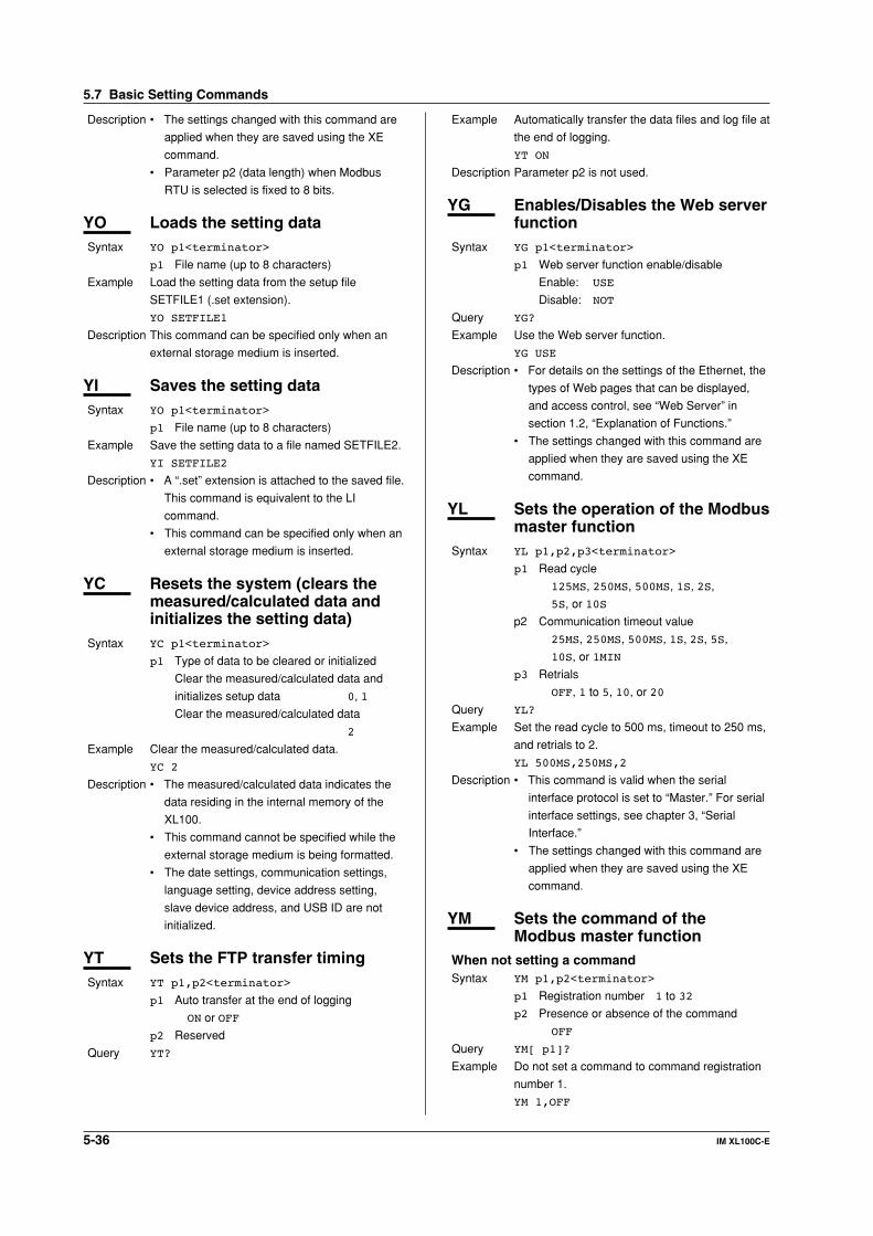
5-36 IM XL100C-E
Description • The settings changed with this command are
applied when they are saved using the XE
command.
• Parameter p2 (data length) when Modbus
RTU is selected is fixed to 8 bits.
YO Loads the setting dataSyntax YO p1<terminator>
p1 File name (up to 8 characters)
Example Load the setting data from the setup file
SETFILE1 (.set extension).
YO SETFILE1
Description This command can be specified only when an
external storage medium is inserted.
YI Saves the setting dataSyntax YO p1<terminator>
p1 File name (up to 8 characters)
Example Save the setting data to a file named SETFILE2.
YI SETFILE2
Description • A “.set” extension is attached to the saved file.
This command is equivalent to the LI
command.
• This command can be specified only when an
external storage medium is inserted.
YC Resets the system (clears themeasured/calculated data andinitializes the setting data)
Syntax YC p1<terminator>
p1 Type of data to be cleared or initialized
Clear the measured/calculated data and
initializes setup data 0, 1
Clear the measured/calculated data
2
Example Clear the measured/calculated data.
YC 2
Description • The measured/calculated data indicates the
data residing in the internal memory of the
XL100.
• This command cannot be specified while the
external storage medium is being formatted.
• The date settings, communication settings,
language setting, device address setting,
slave device address, and USB ID are not
initialized.
YT Sets the FTP transfer timingSyntax YT p1,p2<terminator>
p1 Auto transfer at the end of logging
ON or OFF
p2 Reserved
Query YT?
Example Automatically transfer the data files and log file at
the end of logging.
YT ON
Description Parameter p2 is not used.
YG Enables/Disables the Web serverfunction
Syntax YG p1<terminator>
p1 Web server function enable/disable
Enable: USE
Disable: NOT
Query YG?
Example Use the Web server function.
YG USE
Description • For details on the settings of the Ethernet, the
types of Web pages that can be displayed,
and access control, see “Web Server” in
section 1.2, “Explanation of Functions.”
• The settings changed with this command are
applied when they are saved using the XE
command.
YL Sets the operation of the Modbusmaster function
Syntax YL p1,p2,p3<terminator>
p1 Read cycle
125MS, 250MS, 500MS, 1S, 2S,
5S, or 10S
p2 Communication timeout value
25MS, 250MS, 500MS, 1S, 2S, 5S,
10S, or 1MIN
p3 Retrials
OFF, 1 to 5, 10, or 20
Query YL?
Example Set the read cycle to 500 ms, timeout to 250 ms,
and retrials to 2.
YL 500MS,250MS,2
Description • This command is valid when the serial
interface protocol is set to “Master.” For serial
interface settings, see chapter 3, “Serial
Interface.”
• The settings changed with this command are
applied when they are saved using the XE
command.
YM Sets the command of theModbus master function
When not setting a commandSyntax YM p1,p2<terminator>
p1 Registration number 1 to 32
p2 Presence or absence of the command
OFF
Query YM[ p1]?
Example Do not set a command to command registration
number 1.
YM 1,OFF
5.7 Basic Setting Commands
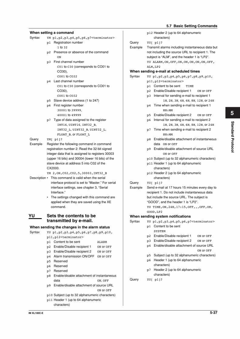
5-37IM XL100C-E
1
2
3
4
5
6
7
App
Index
Stan
dard
Pro
toco
l
When setting a commandSyntax YM p1,p2,p3,p4,p5,p6,p7<terminator>
p1 Registration number
1 to 32
p2 Presence or absence of the command
ON
p3 First channel number
C01 to C30 (corresponds to CO01 to
CO30),
CO01 to CO32
p4 Last channel number
C01 to C30 (corresponds to CO01 to
CO30),
CO01 to CO32
p5 Slave device address (1 to 247)
p6 First register number
30001 to 39999,
40001 to 49999
p7 Type of data assigned to the register
INT16, UINT16, INT32_B,
INT32_L, UINT32_B, UINT32_L,
FLOAT_B, or FLOAT_L
Query YM[ p1]?
Example Register the following command in command
registration number 2: Read the 32-bit signed
integer data that is assigned to registers 30003
(upper 16 bits) and 30004 (lower 16 bits) of the
slave device at address 5 into C02 of the
CX2000.
YM 2,ON,C02,C02,5,30003,INT32_B
Description • This command is valid when the serial
interface protocol is set to “Master.” For serial
interface settings, see chapter 3, “Serial
Interface.”
• The settings changed with this command are
applied when they are saved using the XE
command.
YU Sets the contents to betransmitted by e-mail.
When sending the changes in the alarm statusSyntax YU p1,p2,p3,p4,p5,p6,p7,p8,p9,p10,
p11,p12<terminator>
p1 Content to be sent ALARM
p2 Enable/Disable recipient 1 ON or OFF
p3 Enable/Disable recipient 2 ON or OFF
p4 Alarm transmission ON/OFF ON or OFF
p5 Reserved
p6 Reserved
p7 Reserved
p8 Enable/disable attachment of instantaneous
data ON, OFF
p9 Enable/disable attachment of source URL
ON or OFF
p10 Subject (up to 32 alphanumeric characters)
p11 Header 1 (up to 64 alphanumeric
characters)
p12 Header 2 (up to 64 alphanumeric
characters)
Query YU[ p1]?
Example Transmit alarms including instantaneous data but
not including the source URL to recipient 1. The
subject is “ALM”, and the header 1 is “LP2”.
YU ALARM,ON,OFF,ON,ON,ON,ON,ON,OFF,
ALM,LP2
When sending e-mail at scheduled timesSyntax YU p1,p2,p3,p4,p5,p6,p7,p8,p9,p10,
p11,p12<terminator>
p1 Content to be sent TIME
p2 Enable/Disable recipient 1 ON or OFF
p3 Interval for sending e-mail to recipient 1
1H, 2H, 3H, 4H, 6H, 8H, 12H, or 24H
p4 Time when sending e-mail to recipient 1
HH:MM
p5 Enable/Disable recipient 2 ON or OFF
p6 Interval for sending e-mail to recipient 2
1H, 2H, 3H, 4H, 6H, 8H, 12H, or 24H
p7 Time when sending e-mail to recipient 2
HH:MM
p8 Enable/disable attachment of instantaneous
data ON or OFF
p9 Enable/disable attachment of source URL
ON or OFF
p10 Subject (up to 32 alphanumeric characters)
p11 Header 1 (up to 64 alphanumeric
characters)
p12 Header 2 (up to 64 alphanumeric
characters)
Query YU[ p1]?
Example Send e-mail at 17 hours 15 minutes every day to
recipient 1. Do not include instantaneous data
but include the source URL. The subject is
“GOOD”, and the header 1 is “LP2”.
YU TIME,ON,24H,17:15,OFF,,,OFF,ON,
GOOD,LP2
When sending system notificationsSyntax YU p1,p2,p3,p4,p5,p6,p7<terminator>
p1 Content to be sent
SYSTEM
p2 Enable/Disable recipient 1 ON or OFF
p3 Enable/Disable recipient 2 ON or OFF
p4 Enable/disable attachment of source URL
ON or OFF
p5 Subject (up to 32 alphanumeric characters)
p6 Header 1 (up to 64 alphanumeric
characters)
p7 Header 2 (up to 64 alphanumeric
characters)
Query YU[ p1]?
5.7 Basic Setting Commands

5-38 IM XL100C-E
Example Send system notification e-mail messages
including the source URL to recipient 1. The
subject is “SystemAlert”, and header 1 is “LP2”.
YU SYSTEM,ON,OFF,ON,SystemAlert,LP2
YV Sets the e-mail transmissionrecipient address
Syntax YV p1,p2<terminator>
p1 Recipient selection
Recipient 1: 1
Recipient 2: 2
p2 Recipient address (up to 150 alphanumeric
characters)
Query YV[p1]?
Example Set recipient 1 to “[email protected]” and
YV 1,[email protected] [email protected]
Description • To set multiple recipients, separate each
recipient with a space.
• For e-mail settings, see section 2.11, “Setting
the E-mail Transmission Function” and 2.13,
“Starting/Stopping E-mail Transmissions.”
YW Sets the e-mail transmissionsender address
Syntax YW p1<terminator>
p1 Sender address (up to 64 alphanumeric
characters)
Query YW?
Example Set the sender address to “XL100.”
YW XL100
Description For e-mail settings, see section 2.11, “Setting the
E-mail Transmission Function” and 2.13,
“Starting/Stopping E-mail Transmissions.”
YX Sets the e-mail SMTP servername
Syntax YX p1,p2<terminator>
p1 SMTP server name (up to 64 alphanumeric
characters)
p2 Port number 0 to 65535
Query YX?
Example Set the SMTP server to “mhs.good.com” and
port number to “25”.
YX mhs.good.com,25
Description For e-mail settings, see section 2.11, “Setting the
E-mail Transmission Function” and 2.13,
“Starting/Stopping E-mail Transmissions.”
5.8 Output Commands(Control)
BO Sets the byte output orderSyntax BO p1<terminator>
p1 Byte order
Output the data MSB first: 0
Output the data LSB first: 1
Query BO?
Example Output the data MSB first.
BO 0
Description This command applies to the byte order of
numerical data during binary output.
CS Sets the checksumSyntax CS p1<terminator>
p1 Checksum enable/disable
Disable: 0
Enable: 1
Query CS?
Example Enable the checksum.
CS 1
Description Can be used only during serial communications.
IF Sets the status filterSyntax IF p1<terminator>
p1 Status filter value
0.0.0.0 to 255.255.255.255
Query IF?
Example Set the status filter value to 1.0.4.0.
IF 1.0.4.0
Description For details, see chapter 7, “Status.”
CC Disconnects the Ethernetconnection
Syntax CC p1<terminator>
p1 Connection disconnect 0
Query IF?
Example Disconnect the Ethernet connection.
CC 0
Description Can be used only during Ethernet
communications.
NoteInitialization of BO/CS/IF command settings
• For serial communication
Settings entered using the BO/CS/IF commands revert to
their initial values when the XL100 is reset, when the
XL100 is power cycled, or when the XE command is
executed normally.
• Byte output order, checksum: 0
• Status filter: 000.000.000.000
If the XL100 is reset, you must reconfigure these settings.
• For Ethernet communications
5.8 Output Commands (Control)

5-39IM XL100C-E
1
2
3
4
5
6
7
App
Index
Stan
dard
Pro
toco
l
Settings entered using the BO/IF commands revert to their
initial values when the connection to the XL100 is cut.
After reconnecting the XL100, you must reconfigure the
settings.
ID Outputs the system data (queryonly)
Syntax ID p1, p2, p3, p4<terminator>
p1 Maker name YOKOKGAWA
p2 Model XL100
p3 XL100 serial number
16 alphanumeric characters
p4 Terminal block serial number
16 alphanumeric characters
p5 Firmware revision
Verx.xx
(where x.xx are
alphanumeric characters)
Query ID?
Description Parameter p4, the terminal block serial number,
is undefined if the terminal block unit is not
connected.
5.9 Output Commands (Setting/Measurement/Data Output)
FC Outputs the screen image dataSyntax FC p1<terminator>
p1 Screen image data output GET
Example Output the screen image data from the XL100.
FC GET
Description Captures the current displayed screen on the
XL100 and outputs the data in BMP format.
FE Outputs the setting dataSyntax FE p1,p2,p3,p4,p5,p6,p7,p8,p9,p10,
p11<terminator>
p1 Output data type
Setting data of setting commands: 0
Decimal place and unit information: 1
Setting data of basic setting commands: 2
Reserved: 3
Setting data file: 4
p2 First channel number
For 8 ch input: 01 to 08,
For 16 ch input: 01 to 16
<Numeric value> 00(OFF)
p3 Last channel number
For 8 ch input: 01 to 08,
For 16 ch input: 01 to 16
<Numeric value> 00(OFF)
p4 First pulse measurement channel number:
PL01, PL00(OFF)
p5 Last pulse measurement channel number:
PL01, PL00(OFF)
p6 First logic input channel number
DI01 to DI02, DI00(OFF)
p7 Last logic input channel number
DI01 to DI02, DI00(OFF)
p8 First calculation channel number
CA01 to CA32, CA00(OFF)
p9 Last calculation channel number
CA01 to CA32, CA00(OFF)
p10 First communication channel number
CO01 to CO32, CA00(OFF)
p11 Last communication channel number
CO01 to CO32, CA00(OFF)
Example Get the decimal place and unit for channels 01 to
12 and pulse channel.
FE 1,01,12,PL01,PL01
Description • Set the first channel number and last channel
number parameters so that the last channel
number is greater than or equal to the first
channel number.
• Parameters p2, p3, p4, p5, p6, p7, p8, p9,
p10, and p11 are valid when p1 is set to 0, 1,
2, or 3.
5.9 Output Commands (Setting/Measurement/Data Output)

5-40 IM XL100C-E
FD Outputs the most recentmeasured/calculated data
Syntax FD p1,p2,p3,p4,p5,p6,p7,p8,p9,p10,
p11<terminator>
p1 Output data type
Output the most recent measured/calculated
data in ASCII format: 0
Output the most recent measured/calculated
data in BINARY format: 1
Reserved: 4, 5
p2 First channel number
For 8 ch input: 01 to 08,
For 16 ch input: 01 to 16
<Numeric value> 00(OFF)
p3 Last channel number
For 8 ch input: 01 to 08,
For 16 ch input: 01 to 16
<Numeric value> 00(OFF)
p4 First pulse measurement channel number:
PL01, PL00(OFF)
p5 Last pulse measurement channel number:
PL01, PL00(OFF)
p6 First logic input channel number
DI01 to DI02, DI00(OFF)
p7 Last logic input channel number
DI01 to DI02, DI00(OFF)
p8 First calculation channel number
CA01 to CA32, CA00(OFF)
p9 Last calculation channel number
CA01 to CA32, CA00(OFF)
p10 First communication channel number
CO01 to CO32, CA00(OFF)
p11 Last communication channel number
CO01 to CO32, CA00(OFF)
Example Output from the XL100 the most recent
measurement of channels 1 to 5, pulse
measurement data, and logic measurement data
1 and 2 and the calculated data of channels 1 to
5 in ASCII data format.
FD 0,01,05,PL01,PL01,DI01,DI02,CA01,
CA05,CO00,CO00
FD 0,01,05
Description • The most recent measured/calculated data
corresponds to the most recent measured/
calculated data in the internal memory when
the XL100 receives the FD command.
• Set the first channel number and last channel
number parameters so that the last channel
number is greater than or equal to the first
channel number.
FL Outputs the log and alarmsummary
Syntax FL p1,p2<terminator>
p1 Log type
Communication: COM
FTP client: FTPC
Error message: ERR
Key login: KEY
Web operation: WEB
E-mail: EMAIL
Alarm summary: ALARM
Reserved: MSG
p2 Maximum read length of the log
When p1 is COM: 1 to 200
When p1 is ALARM: 1 to 120
When p1 is some type other than the above:
1 to 50
Example Output the 10 most recent error message logs.
FL ERR,10
Description • Outputs the log that is stored in the XL100.
• If p2 is omitted, all written logs are output.
IS Outputs status informationSyntax IS p1<terminator>
p1 Status information output 0
Example Output status information.
IS 0
Description The output status can be masked using the
status filter (IF command).
FU Outputs the user levelSyntax FU p1<terminator>
p1 User information output 0
Example Output user information.
FU 0
Description Outputs the information of the user currently
connected to the XL100.
ME Outputs the data stored on theexternal storage medium
Syntax ME p1,p2,p3<terminator>
p1 Operation type
Output the file list: DIR
Output (first time): GET
Output (subsequent times). This parameter
is used to output the remaining data when
the first output operation is not adequate:
NEXT
Retransmit the previous output: RESEND
Delete: DEL
Outputs the subsequent file list after the file
list is output using the DIRNEXT DIR
command. The number of output lists is the
p3 value specified with the DIR command. If
this command is executed after all lists have
been output, only the free space of the
storage medium is output.
p2 File name (26 alphanumeric characters)
Specify using a full path.
p3 Maximum number of output file lists
1 to 100
5.9 Output Commands (Setting/Measurement/Data Output)

5-41IM XL100C-E
1
2
3
4
5
6
7
App
Index
Stan
dard
Pro
toco
l
If omitted, all the file lists in the specified
directory are output.
Example • Output the list of all files in the root directory.
ME DIR,/
• Output 10 files of the file list of the root
directory.
ME DIR,/,10
• Output the list of all files in the DATA0
directory.
ME DIR,/DATA0/*.*
• Output the list of all display data files in the
DATA0 directory.
ME DIR,/DATA0/*.DDS
• Output the data in the file 72615100.DDS in
the DATA0 directory.
ME GET,/DATA0/72615100.DDS
Description • This command is valid for the specified save
destination and load destination medium.
• Parameter p2 is valid when p1 is set to DIR,
GET, or DEL.
• Parameter p3 is valid when p1 is set to DIR.
• This command can be used to output data
over the communication interface (Ethernet or
serial) that was selected with the XO
command.
• If an error occurs during data transmission,
(p1=) RESEND can be used to retransmit the
data.
5.10 Output Commands (RS-485and USB DedicatedCommands)
ESC O Opens the deviceThe ASCII code of ESC is 1BH.
See appendix 1, “ASCII Character Codes.”
Syntax ESC O p1<terminator>
p1 Device address 01 to 99
Example Open the device at address 01, and enable all
commands.
ESC O 01
Description • Specifies the address of the device with which
to communicate.
• Only one device can be opened at any given
time.
• When a device is opened with the ESC O
command, another device that is currently
open is automatically closed.
• When this command is received correctly, the
XL100 transmits the data “ESC O ”.
• Normally, either CR+LF or LF can be used as
a terminator for communication commands.
However, the terminator for this command
must be set to CR+LF.
ESC C Closes the deviceThe ASCII code of ESC is 1BH.
See appendix 1, “ASCII Character Codes.”
Syntax ESC C p1<terminator>
p1 Device address 01 to 99
Example Close the device whose address is 01.
ESC C 001
Description • Clears the current connection with the device.
• When this command is received correctly, the
XL100 transmits the data “ESC C ”.
• Normally, either CR+LF or LF can be used as
a terminator for communication commands.
However, the terminator for this command
must be set to CR+LF.
5.10 Output Commands (RS-485 and USB Dedicated Commands)

5-42 IM XL100C-E
5.11 Maintenance/TestCommands (Available whenusing the maintenance/testserver function via Ethernetcommunications)
close Disconnects the connectionbetween other devices
Syntax close,p1,p2:p3<terminator>
p1 Port on the XL100 side
0 to 65535
p2 IP address on the PC side
0.0.0.0 to 255.255.255.255
p3 Port on the PC side
0 to 65535
Example
close,349,192.168.111.24:1054
E0
Description This command cannot be used to disconnect a
server port. Also, it cannot disconnect the XL100
being operated. Use the quit command for this
purpose.
con Outputs connection informationSyntax con<terminator>
Example
con
EA
00/00/00 12:34:56
Active connections
Proto Local Address Foreign Address
State
TCP 192.168.111. 24:34159
192.168.111. 24:1053 ESTABLISHED
TCP 0. 0. 0. 0:34155 0. 0. 0. 0: 0
LISTEN
TCP 0. 0. 0. 0:34159 0. 0. 0. 0: 0
LISTEN
TCP 0. 0. 0. 0:34150 0. 0. 0. 0: 0
LISTEN
EN
TCP: Protocol used
Local Address: The XL100 socket address.
Displays “IP address:port number”
Foreign Address: The destination socket
address. Displays “IP address:port number”
State: Connection status
ESTABLISHED: Connection established
eth Outputs Ethernet statisticalinformation
Syntax eth<terminator>
Example
eth
EA
00/00/00 12:34:56
Ethernet Statistics
Name In Pkt In Err Out Pkt Out Err
16 Coll
lo0 0 0 0 0 0
mb0 74 0 64 0 0
EN
help Outputs helpSyntax help [,p1]<terminator>
p1 Command name
(close, con, eth, help, net, quit)
Example
help
EA
con - echo connection information
eth - echo ethernet information
help - echo help
net - echo network status
quit - close this connection
EN
net Outputs network statisticalinformation
Syntax net<terminator>
Example
net
EA
00/00/00 12:34:56
Network Status
APP: power on time = 00/00/00
12:34:56
APP: applalive = disable
APP: genedrops = 0
APP: diagdrops = 0
APP: ftpsdrops = 0
TCP: keepalive = 30 s
TCP: connects = 14
TCP: closed = 0
TCP: timeoutdrop = 0
TCP: keepdrops = 0
TCP: sndtotal = 53
TCP: sndbyte = 0
TCP: sndrexmitpack = 0
TCP: sndrexmitbyte = 1
TCP: rcvtotal = 0
TCP: rcvbyte = 0
DLC: 16 collisions = 0
EN
TCP: keepalive:Keepalive check cycle
TCP: connects:Total number of connections
established
5.11 Maintenance/Test Commands
5-43IM XL100C-E
1
2
3
4
5
6
7
App
Index
Stan
dard
Pro
toco
l
TCP: closed: Total number of dropped
connections
TCP: timeoutdrop: Total number of dropped
connections due to TCP retransmission
timeout. When the transmitted packet (the
unit of transmitted data) is not received, the
packet is automatically retransmitted at a
predetermined time interval. If the packet is
not received after 14 retransmissions,
timeout occurs and the connection is
dropped.
TCP: keepdrops: Total number of dropped
connections due to TCP keepalive timeout
TCP: sndtotal: Total number of transmitted
packets.
TCP: sndbyte: Total number of transmitted bytes
TCP: sndrexmitpack: Total number of
retransmitted packets
TCP: sndrexmitbyte: Total number of
retransmitted bytes
TCP: rcvtotal: Total number of received packets
TCP: rcvbyte: Total number of received bytes
DLC: 16 collisions: Number of collision incidents.
A collision occurs when two or more
instruments on the network attempt to
transmit simultaneously. The tendency for
collisions to occur increases when the
network is congested. 16 collisions refer to
16 consecutive collision incidents.
quit Disconnects the connection ofthe device being operated
Syntax quit<terminator>
5.11 Maintenance/Test Commands
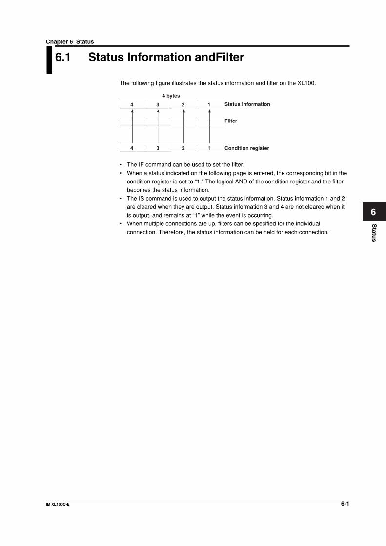
6-1IM XL100C-E
1
2
3
4
5
6
7
App
Index
Statu
s
6.1 Status Information andFilter
The following figure illustrates the status information and filter on the XL100.
Status information
Filter
Condition register
4 bytes
4 3 2 1
4 3 2 1
• The IF command can be used to set the filter.• When a status indicated on the following page is entered, the corresponding bit in the
condition register is set to “1.” The logical AND of the condition register and the filterbecomes the status information.
• The IS command is used to output the status information. Status information 1 and 2
are cleared when they are output. Status information 3 and 4 are not cleared when itis output, and remains at “1” while the event is occurring.
• When multiple connections are up, filters can be specified for the individual
connection. Therefore, the status information can be held for each connection.
Chapter 6 Status

6-2 IM XL100C-E
6.2 Bit Structure of the Status Information
The four groups of status information described below are output in response to a statusinformation output request using the IS command. For the output format, see “ASCII
Output Response Syntax” in section 5.2, “Response Syntax.”
Status Information 1
Bit Name Description
0 – –
1 Medium access complete Set to 1 when the display, manual sampled, or screenimage data file is finished being saved to the externalstorage medium.Set to 1 when setting data is successfully saved or loaded.
2 – –
3 – –
4 – –
5 – –
6 – –
7 – –
Status Information 2
Bit Name Description
0 Measurement dropout Set to 1 when the measurement process could not keep up.
1 Decimal point/unit information Set to 1 when the decimal point/unit information is changechange changed.
2 Command error Set to 1 when there is a command syntax error.
3 Execution error Set to 1 when an error occurs during command execution.
4 – –
5 – –
6 – –
7 – –
Status Information 3
Bit Name Description
0 – –
1 – –
2 Memory end Set to 1 while the free space in the internal memory orexternal storage medium is low.
3 Execution error Set to 1 when an error occurs during command execution.
4 – –
5 – –
6 – –
7 – –
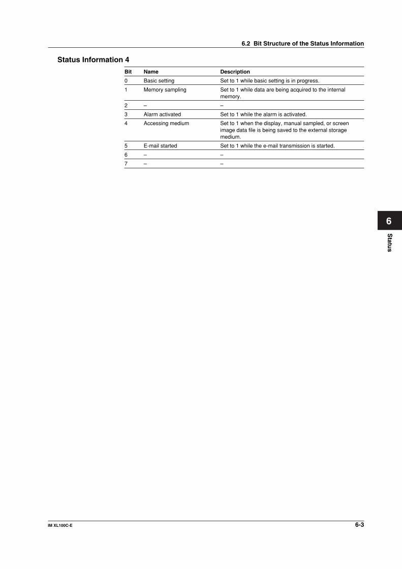
6-3IM XL100C-E
1
2
3
4
5
6
7
App
Index
Statu
s
Status Information 4
Bit Name Description
0 Basic setting Set to 1 while basic setting is in progress.
1 Memory sampling Set to 1 while data are being acquired to the internalmemory.
2 – –
3 Alarm activated Set to 1 while the alarm is activated.
4 Accessing medium Set to 1 when the display, manual sampled, or screenimage data file is being saved to the external storagemedium.
5 E-mail started Set to 1 while the e-mail transmission is started.
6 – –
7 – –
6.2 Bit Structure of the Status Information
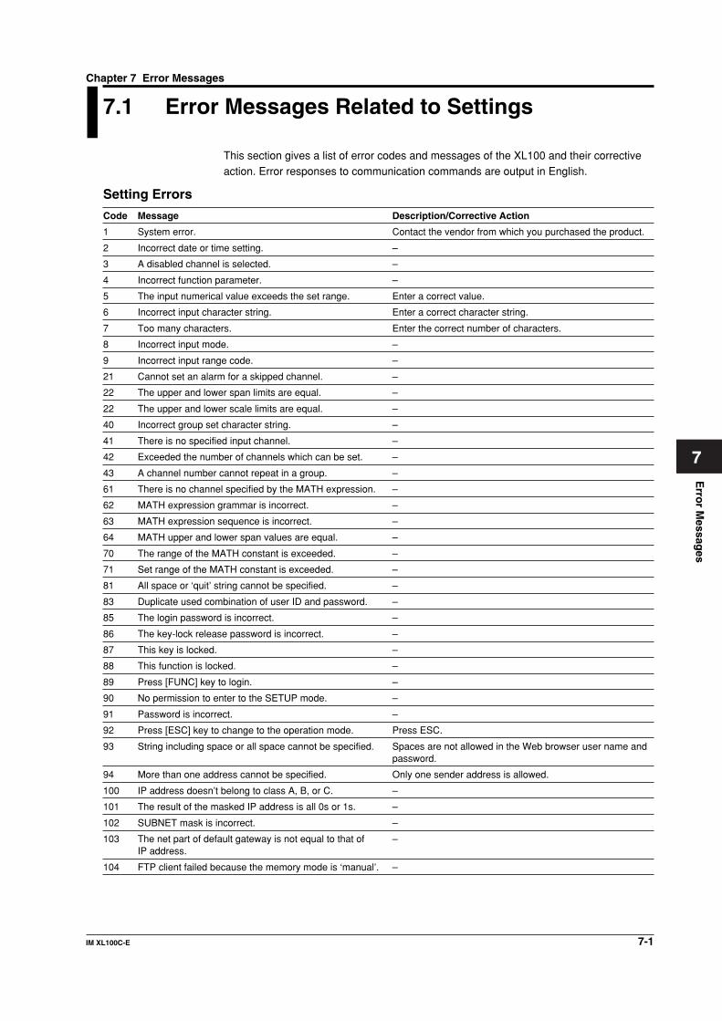
7-1IM XL100C-E
1
2
3
4
5
6
7
App
Index
Erro
r Messag
es
7.1 Error Messages Related to Settings
This section gives a list of error codes and messages of the XL100 and their correctiveaction. Error responses to communication commands are output in English.
Setting Errors
Code Message Description/Corrective Action
1 System error. Contact the vendor from which you purchased the product.
2 Incorrect date or time setting. –
3 A disabled channel is selected. –
4 Incorrect function parameter. –
5 The input numerical value exceeds the set range. Enter a correct value.
6 Incorrect input character string. Enter a correct character string.
7 Too many characters. Enter the correct number of characters.
8 Incorrect input mode. –
9 Incorrect input range code. –
21 Cannot set an alarm for a skipped channel. –
22 The upper and lower span limits are equal. –
22 The upper and lower scale limits are equal. –
40 Incorrect group set character string. –
41 There is no specified input channel. –
42 Exceeded the number of channels which can be set. –
43 A channel number cannot repeat in a group. –
61 There is no channel specified by the MATH expression. –
62 MATH expression grammar is incorrect. –
63 MATH expression sequence is incorrect. –
64 MATH upper and lower span values are equal. –
70 The range of the MATH constant is exceeded. –
71 Set range of the MATH constant is exceeded. –
81 All space or ‘quit’ string cannot be specified. –
83 Duplicate used combination of user ID and password. –
85 The login password is incorrect. –
86 The key-lock release password is incorrect. –
87 This key is locked. –
88 This function is locked. –
89 Press [FUNC] key to login. –
90 No permission to enter to the SETUP mode. –
91 Password is incorrect. –
92 Press [ESC] key to change to the operation mode. Press ESC.
93 String including space or all space cannot be specified. Spaces are not allowed in the Web browser user name andpassword.
94 More than one address cannot be specified. Only one sender address is allowed.
100 IP address doesn’t belong to class A, B, or C. –
101 The result of the masked IP address is all 0s or 1s. –
102 SUBNET mask is incorrect. –
103 The net part of default gateway is not equal to that of –IP address.
104 FTP client failed because the memory mode is ‘manual’. –
Chapter 7 Error Messages

7-2 IM XL100C-E
Execution Errors
Code Message Description/Corrective Action
150 This action is not possible because sampling is in –progress.
151 This action is not possible during sampling or calculating. –
152 This action is not possible because saving is in progress. Wait for the data save operation to complete.
153 This action is not possible because formatting is in Wait for the format operation to complete.progress.
155 The message is not written while sampling is stopped. –
160 Cannot load the specified data. Change the memory –setting.
7.1 Error Messages Related to Settings

7-3IM XL100C-E
1
2
3
4
5
6
7
App
Index
Erro
r Messag
es
7.2 Error Messages Related to Operation
This section gives a list of error codes and messages of the XL100 and their correctiveaction. Error responses to communication commands are output in English.
External Storage Media Operation Errors
Code Message Description/Corrective Action
200 Operation aborted because an error was found in media. Check the external storage medium.
201 Not enough free space on media. Replace the external storage medium.
202 Media is read-only. Set the external storage medium to enable writing.
210 Media has not been inserted. Insert an external storage medium.
211 Media is damaged or not formatted. Replace the external storage medium or format it.
212 Format error. Format the external storage medium again.
213 The file is read-only. Access another file or make the file write-enable.
214 There is no file or directory. –
215 Exceeded the allowable number of files. Replace the external storage medium.Delete unneeded files.
216 The file or directory name is incorrect. –
217 Unknown file type. Specify another file.
218 Directory exists. Delete the directory or change –directory name.
219 Invalid file or directory operation. Tried to delete multiple directory levels.
220 The file is already in use. Try again later. Wait until the file is accessible.
230 There is no setting file. Specify another file.
231 Abnormal setting exists in file. Specify another file.
Review Display Errors
Code Message Description/Corrective Action
232 There is no available data. Displayed when showing the review display.Specify another file.
233 The specified review data do not exist. Displayed when showing the review display.
234 The specified channel is not assigned to the display group. –
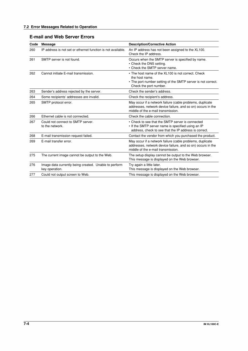
7-4 IM XL100C-E
E-mail and Web Server Errors
Code Message Description/Corrective Action
260 IP address is not set or ethernet function is not available. An IP address has not been assigned to the XL100.Check the IP address.
261 SMTP server is not found. Occurs when the SMTP server is specified by name.• Check the DNS setting.• Check the SMTP server name.
262 Cannot initiate E-mail transmission. • The host name of the XL100 is not correct. Checkthe host name.
• The port number setting of the SMTP server is not correct.Check the port number.
263 Sender’s address rejected by the server. Check the sender’s address.
264 Some recipients’ addresses are invalid. Check the recipient’s address.
265 SMTP protocol error. May occur if a network failure (cable problems, duplicateaddresses, network device failure, and so on) occurs in themiddle of the e-mail transmission.
266 Ethernet cable is not connected. Check the cable connection.
267 Could not connect to SMTP server. • Check to see that the SMTP server is connectedto the network. • If the SMTP server name is specified using an IP
address, check to see that the IP address is correct.
268 E-mail transmission request failed. Contact the vendor from which you purchased the product.
269 E-mail transfer error. May occur if a network failure (cable problems, duplicateaddresses, network device failure, and so on) occurs in themiddle of the e-mail transmission.
275 The current image cannot be output to the Web. The setup display cannot be output to the Web browser.This message is displayed on the Web browser.
276 Image data currently being created. Unable to perform Try again a little later.key operation. This message is displayed on the Web browser.
277 Could not output screen to Web. This message is displayed on the Web browser.
7.2 Error Messages Related to Operation

7-5IM XL100C-E
1
2
3
4
5
6
7
App
Index
Erro
r Messag
es
FTP Client ErrorsThe detail code does not appear in the error message on the screen. You can view the
code on the FTP log display of the XL100 or using the FTP log output via communications.
Code Message
280 IP address is not set or FTP function is not available.Further details are provided by the character string that appears after error code 280.
Character String and Details
HOSTADDRAn IP address has not been assigned to the XL100.Check the IP address.
DORMANTInternal processing error.*1
LINKData link is disconnected.Check the cable connection.
281 FTP mail box operation error.Further details are provided by the character string that appears after error code 281.
Character String and Details
MAILInternal processing error.*1
STATUSInternal processing error.*1
TIMEOUTInternal processing error.*1
PRIORITYInternal processing error.*1
NVRAMInternal processing error.*1
282 FTP control connection error.Further details are provided by the character string that appears after error code 282.
Character String and Details
HOSTNAMEFailed the DNS lookup (search the IP address corresponding to the host name).Check the DNS setting and the destination host name.*1
TCPIPInternal processing error.*1
UNREACHFailed to connect to a control connection server.Check the address setting and that the server is running.
OOBINLINEInternal processing error.*1
NAMEInternal processing error.*1
CTRLThe control connection does not exist.Check that the server does not drop the connection and that it responds within the propertime period.
IACFailed to respond in the TELNET sequence.Check that the server does not drop the connection and that it responds within the propertime period.
ECHOFailed to transmit data on the control connection.Check that the server does not drop the connection and that it responds within the propertime period.
REPLYFailed to receive data on the control connection.Check that the server does not drop the connection and that it responds within the propertime period.
SERVERThe server is not in a condition to provide the service.Check that the server is in a condition in which service can be provided.
7.2 Error Messages Related to Operation

7-6 IM XL100C-E
Code Message
283 FTP command was not accepted.Further details are provided by the character string that appears after error code 283.
Character String and Details
USERFailed user name verification.Check the user name setting.
PASSFailed password verification.Check the password setting.
ACCTFailed account verification.Check the account setting.
TYPEFailed to change the transfer type.Check that the server supports the binary transfer mode.
CWDFailed to change the directory.Check the initial path setting.
PORTFailed to set the transfer connection.Check that the security function is disabled.
PASVFailed to set the transfer connection.Check that the server supports PASV commands.
SCANFailed to read the transfer connection settings.
Check that proper response to the PASV command is received from the server.
284 FTP transfer setting error.Further details are provided by the character string that appears after error code 284.
Character String and Details
MODEInternal processing error.*1
LOCALInternal processing error.*1
REMOTEThe destination file name is not correct.Check that you have the authority to create or overwrite files.
ABORTFile transfer abort was requested by the server.
Check the server for the reason for the abort request.
285 FTP data connection error.Further details are provided by the character string that appears after error code 285.
Character String and Details
SOCKETFailed to create a socket for the transfer connection.*2
BINDFailed the transfer connection command.*2
CONNECTFailed the transfer connection.*2
LISTENFailed the transfer connection reception.*2
ACCEPTFailed to accept the transfer connection.*2
SOCKNAMEInternal processing error.*2
RECVFailed to receive data over the transfer connection.*2
SENDFailed to send data over the transfer connection.*2
7.2 Error Messages Related to Operation

7-7IM XL100C-E
1
2
3
4
5
6
7
App
Index
Erro
r Messag
es
Code Message
286 FTP file transfer error.Further details are provided by the character string that appears after error code 286.
Character String and Details
READInternal processing error.*1
WRITEInternal processing error.*1
*1 Contact the vendor from whom you purchased the product.*2 These errors may occur if the network experiences trouble during the data transmission (bad
cable connection, duplicate addresses, network equipment failure).
NoteThe FTP client function on the XL100 has a timer function that drops the connection ifthere is no data transfer for two minutes. If the server does not respond within this timeperiod, the transfer fails.
7.2 Error Messages Related to Operation
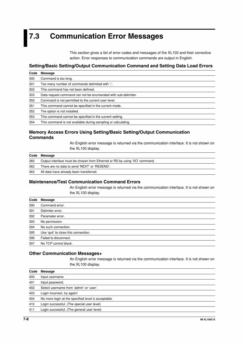
7-8 IM XL100C-E
7.3 Communication Error Messages
This section gives a list of error codes and messages of the XL100 and their correctiveaction. Error responses to communication commands are output in English.
Setting/Basic Setting/Output Communication Command and Setting Data Load Errors
Code Message
300 Command is too long.
301 Too many number of commands delimited with ‘;’.
302 This command has not been defined.
303 Data request command can not be enumerated with sub-delimiter.
350 Command is not permitted to the current user level.
351 This command cannot be specified in the current mode.
352 The option is not installed.
353 This command cannot be specified in the current setting.
354 This command is not available during sampling or calculating.
Memory Access Errors Using Setting/Basic Setting/Output CommunicationCommands
An English error message is returned via the communication interface. It is not shown onthe XL100 display.
Code Message
360 Output interface must be chosen from Ethernet or RS by using ‘XO’ command.
362 There are no data to send ‘NEXT’ or ‘RESEND’.
363 All data have already been transferred.
Maintenance/Test Communication Command ErrorsAn English error message is returned via the communication interface. It is not shown onthe XL100 display.
Code Message
390 Command error.
391 Delimiter error.
392 Parameter error.
393 No permission.
394 No such connection.
395 Use ‘quit’ to close this connection.
396 Failed to disconnect.
397 No TCP control block.
Other Communication Messages+An English error message is returned via the communication interface. It is not shown on
the XL100 display.
Code Message
400 Input username.
401 Input password.
402 Select username from ‘admin’ or ‘user’.
403 Login incorrect, try again!
404 No more login at the specified level is acceptable.
410 Login successful. (The special user level)
411 Login successful. (The general user level)

7-9IM XL100C-E
1
2
3
4
5
6
7
App
Index
Erro
r Messag
es
Code Message
420 Connection has been lost.
421 The number of simultaneous connection has been exceeded.
422 Communication has timed-out.
ModBus Master Error LogAn English error message is returned via the communication interface. It is not shown onthe XL100 display.
Code Message
700 Data could not be received within communication loop time.
701 Connection to some slave is suspended.
702 Connection to slave(s) has recovered.
7.3 Communication Error Messages

App-1IM XL100C-E
1
2
3
4
5
6
7
AppApp
Index
Ap
pen
dix
Appendix 1 ASCII Character Codes
0
1
2
3
4
5
6
7
8
9
A
B
C
D
E
F
0
LF
CR
1
ESC
2
SP
#
%
&
(
)
*
+
–
.
/
3
0
1
2
3
4
5
6
7
8
9
:
4
@
A
B
C
D
E
F
G
H
I
J
K
L
M
N
O
5
P
Q
R
S
T
U
V
W
X
Y
Z
•
_
6
a
b
c
d
e
f
g
h
i
j
k
l
m
n
o
7
p
q
r
s
t
u
v
w
x
y
z
8 9 A B
-
C D E F
Upper 4 bits
Lo
wer
4 b
its
Appendix

App-2 IM XL100C-E
Appendix 2 Login Process
You log into the XL100 from your PC to use the functionality of the setting/measurementserver and the maintenance/test server via the Ethernet interface. If you complete the
procedure successfully up to login complete in the following figure, the commands inchapter 5 become functional.When Using the Ethernet Login Function of the XL100
E1 403
E1 403
Yes
No
No
No
No No
No
E1 404
E1 421
Connect
Disconnect
E1 422
Disconnect
E1 420
Disconnect Login complete
Within 3 retries?*2
Within 3 retries?*3
Wait 5 s
E1 401
E0
E1 400
Entered "quit"?
Verification match?
Within the number of simultaneous uses?*3
Within 2 minutes?
Within the number of connections*1
Within 2 minutes?
User name
Password
Increment retry count
1
1
1
1
Stop
Start Decision
Transition
Code(For a description of the codes and messages, see chapter 8, "Error Messages.")
Response from the XL100 (message omitted)For a description of the response format, see section 6.2.
User entry
*1 Connections cannot exceed the maximum number of connections (see section 2.1).*2 If you attempt to log in using a wrong password four consecutive times, the communication is
dropped (the number of retries for login is three).*3 If you attempt to log in causing the number of simultaneous uses at the administrator or user
level to be exceeded (see section 2.1) four consecutive times, the communication is dropped(even if the password is correct).

App-3IM XL100C-E
1
2
3
4
5
6
7
AppApp
Index
Ap
pen
dix
When Not Using the Ethernet Login Function of the XL100Login as “admin” or “user.”
• You can log into the XL100 as an administrator by accessing the XL100 using theuser name “admin.”
• You can log into the XL100 as a user by accessing the XL100 using the user name
“user.”
E1 403
Yes
No
No
No
No No
No
E1 404
E1 421
Connect
Disconnect
E1 422
Disconnect
E1 420
Disconnect Login complete
Within 3 retries?
Within 3 retries?
E0
E1 402
Entered "quit"?
Verification match?
Within the number of simultaneous uses?
Within the number of connections?
Within 2 minutes?
User name
Increment retry count
1
1
1
1
Appendix 2 Login Process
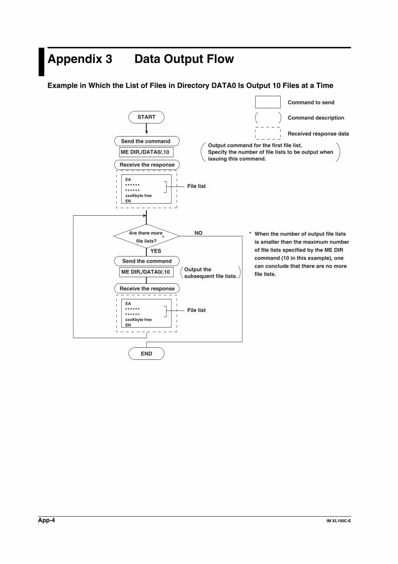
App-4 IM XL100C-E
Appendix 3 Data Output Flow
Example in Which the List of Files in Directory DATA0 Is Output 10 Files at a Time
ME DIR,/DATA0/,10
NO
START
YES
END
Send the command
Are there more
file lists?
Receive the response
ME DIR,/DATA0/,10
*
Send the command
Receive the response
* When the number of output file lists
is smaller than the maximum number
of file lists specified by the ME DIR
command (10 in this example), one
can conclude that there are no more
file lists.
Output command for the first file list.Specify the number of file lists to be output when issuing this command.
Command description
Command to send
Received response data
Output the subsequent file lists.
EA• • • • • •• • • • • •xxxKbyte freeEN
File list
EA• • • • • •• • • • • •xxxKbyte freeEN
File list
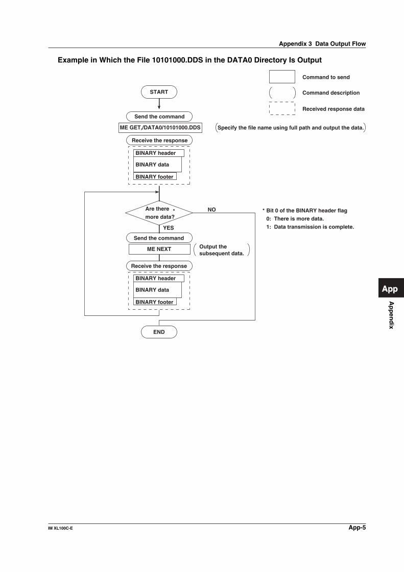
App-5IM XL100C-E
1
2
3
4
5
6
7
AppApp
Index
Ap
pen
dix
Example in Which the File 10101000.DDS in the DATA0 Directory Is Output
ME GET,/DATA0/10101000.DDS
NO
START
YES
END
Send the command
Are there
more data?
Receive the response
BINARY header
BINARY data
BINARY footer
ME NEXT
*
Send the command
BINARY header
BINARY data
BINARY footer
Receive the response
* Bit 0 of the BINARY header flag
0: There is more data.
1: Data transmission is complete.
Specify the file name using full path and output the data.
Command description
Command to send
Received response data
Output the subsequent data.
Appendix 3 Data Output Flow

Index-1IM XL100C-E
1
2
3
4
5
6
7
App
IndexIndex
Ind
ex
Index
Index
Aaccess control ................................................................... 2-18access privilege, granting of ............................................... 1-4account ............................................................................... 2-8administrator ............................................................. 1-4, 2-13affirmative response ............................................................ 5-3AK command .................................................................... 5-30alarm delay time, setting of ............................................... 5-29alarm line, setting of .......................................................... 5-28alarm, setting of ................................................................ 5-27alarm settings .................................................................... 5-31alarm status, acknowledgement of ................................... 5-30alarm summary ................................................................. 5-12ASCII character codes ................................................... App-1ASCII output response syntax ............................................ 5-4automatic file transfer .......................................................... 1-3automatic transfer ............................................................... 2-8average, setting of ............................................................ 5-28
Bbackground color, waveform line width, and alarm lin ...... 5-28bar graph base position, setting of .................................... 5-28basic setting command, setting whether to save or di ...... 5-34basic setting commands ..... 5-31, 5-32, 5-33, 5-34, 5-35, 5-36, 5-37basic syntax ...................................................................... 5-14baud rate ..................................................................... 3-3, 3-6BD command .................................................................... 5-29binary output syntax .......................................................... 5-14block (measured/calculated/FIFO data output) ................. 5-17block member ................................................................... 5-17BO command .................................................................... 5-38BO flag .............................................................................. 5-15burnout setting (query only) .............................................. 5-31BY command .................................................................... 5-29byte output order, setting of .............................................. 5-38bytes, number of ............................................................... 5-16
Ccalculating equation, setting of .......................................... 5-26calculation channels .......................................................... 5-24CC command .................................................................... 5-38channel display color and waveform line width, setti ........ 5-29checksum, setting of ......................................................... 5-38close command ................................................................. 5-42CM command .................................................................... 5-30command name .................................................................. 5-1command-response ............................................................ 5-3commands .......................................................................... 4-4communication channels .................................................. 5-24communication distance ..................................................... 3-5communication error messages .................................. 7-8, 7-9communication function ...................................................... 1-1communication input data ................................................... 4-2communication input data, setting of ................................ 5-30communication interface, selection of ................................. 2-3communication interval ....................................................... 4-4communication log .............................................................. 5-6communication log display ................................................ 2-15communication method, selection of ................................. 5-32communication timeout ............................................... 1-4, 2-5
con command ................................................................... 5-42connection information, outputting of ................................ 5-42connection status, checking ................................................ 2-7connection with other devices, disconnection of ............... 5-42CR+LF ................................................................................. 5-2CS command .................................................................... 5-38CS-RS ................................................................................. 3-2
Ddata length .................................................................. 3-3, 3-6data length (binary output) ................................................ 5-14data output flow .................................................. App-4, App-5data reception control ......................................................... 3-2data sum ........................................................................... 5-14data transmission control .................................................... 3-2date and time setting ......................................................... 5-27DC voltage ........................................................................ 5-23decimal place/unit information ............................................ 5-4Default Gateway ................................................................. 2-4delimiter .............................................................................. 5-2device, closing of .............................................................. 5-41device, opening of ............................................................. 5-41DHCP ................................................................................. 2-3display backlight auto off, setting of .................................. 5-29display, switching of .......................................................... 5-30DNS ................................................................................. 2-4DNS server ......................................................................... 2-4DNS Setting ........................................................................ 2-6DNS, setting of .................................................................. 5-35domain name ...................................................................... 2-4domain suffix ....................................................................... 2-4
Ee-mail and Web server errors ............................................. 7-4e-mail log .......................................................................... 5-11e-mail log display .............................................................. 2-17e-mail message, contents of ............................................. 2-30e-mail, setting the contents to be transmitted ................... 5-37e-mail SMTP server name, setting of ................................ 5-38e-mail transmission ........... 1-5, 2-23, 2-24, 2-25, 2-26, 2-27e-mail transmission recipient address, setting of .............. 5-38e-mail transmission sender address, setting of ................. 5-38e-mail transmission test .................................................... 2-28EM command .................................................................... 5-31END flag ............................................................................ 5-15end trigger, selection of ..................................................... 5-33error log display ................................................................ 2-15error message log ............................................................... 5-8ESC C command .............................................................. 5-41ESC O command .............................................................. 5-41eth command .................................................................... 5-42ETHERNET ......................................................................... 2-6Ethernet communication timeout, setting of ...................... 5-35Ethernet connection, disconnection of .............................. 5-38Ethernet interface, checking the connection status o ......... 2-7Ethernet interface, configuration of ............. 2-3, 2-4, 2-5, 2-6Ethernet interface, connection of ........................................ 2-2Ethernet interface, specifications of .................................... 2-1Ethernet parameters, setting of ........................................... 2-3Ethernet statistical information, outputting of .................... 5-42EV command .................................................................... 5-30execution errors .................................................................. 7-2explanation of functions .............................. 1-2, 1-3, 1-4, 1-5

Index-2 IM XL100C-E
external storage media operation errors ............................. 7-3external storage medium, saving to .................................. 5-30
FFC command .................................................................... 5-39FD command .................................................................... 5-40FE command ..................................................................... 5-39file list 5-13files, transferred .................................................................. 2-8filter ................................................................................. 6-1FL command ..................................................................... 5-40flag (output byte order/checksum/END check) ................. 5-15FTP ................................................................................. 1-1FTP client errors ................................................................. 7-5FTP client, setting of ................................................... 2-8, 2-9FTP destination ................................................................... 2-8FTP log display ................................................................. 2-16FTP server .......................................................................... 1-3FTP server name ................................................................ 2-8FTP test .......................................................... 1-3, 2-11, 2-12FTP transfer timing, setting of ........................................... 5-36FU command .................................................................... 5-40function codes of the Modbus protocol ............................... 4-1
Ggroup, setting of ................................................................ 5-28
Hhandshaking ........................................................................ 3-3handshaking method ........................................................... 3-2header sum ....................................................................... 5-14help command .................................................................. 5-42help, outputting of ............................................................. 5-42hold register ........................................................................ 4-2host name ........................................................................... 2-4HTTP ................................................................................. 1-1
IID command ...................................................................... 5-39identifier (binary data) ....................................................... 5-15IF command ...................................................................... 5-38initial path ............................................................................ 2-9input range parameters ........................................... 5-23, 5-24input range, setting of ....................................................... 5-25input register ....................................................................... 4-2integrated value, calculation of ......................................... 5-16interval .............................................................................. 2-24IP ................................................................................. 1-1IP address ........................................................................... 2-4IP Address Setting .............................................................. 2-6IP address, subnet mask, and default gateway ................ 5-34IPV6 information, querying of ............................................ 5-34IS command ...................................................................... 5-40
Kkeep alive ............................................................................ 2-5keepalive ............................................................................. 1-5keepalive, setting of .......................................................... 5-34key login and auto logout functions, setting of .................. 5-34key login log ........................................................................ 5-9
LLAN port LED ...................................................................... 2-7language, setting of ........................................................... 5-32LF ................................................................................. 5-2LI command ...................................................................... 5-30LO command .................................................................... 5-30log and alarm summary, outputting of ............................... 5-40logging, starting/stopping of .............................................. 5-30logic ............................................................................... 5-23login ......................................................................... 1-4, 2-5login name .......................................................................... 2-8login process ...................................................... App-2, App-3
Mmaintenance/test commands ........................ 5-22, 5-42, 5-43maintenance/test communication command errors ............ 7-8maintenance/test server ...................................................... 1-2manual sampled data ........................................................ 5-18master (of Modbus) ............................................................. 4-1maximum number of simultaneous connections ................. 2-1ME command .................................................................... 5-40measured/calculated binary data syntax ........................... 5-16measured/calculated data ................................................... 5-5memory access error using setting/basic setting/outp ........ 7-8Modbus error response ....................................................... 4-3Modbus Master ................................................................... 1-2Modbus master, data dropout handling of .................. 4-7, 4-8ModBus master error log .................................................... 7-9Modbus master function ...................................................... 4-4Modbus master function, setting the command of ............ 5-36Modbus master function, setting the operation of ............. 5-36Modbus protocol ......................................................... 1-1, 4-1Modbus Slave ..................................................................... 1-2Modbus slave ...................................................................... 1-2monitor .............................................................................. 2-18monitor page ..................................................................... 2-18monitor page, contents of ................................................. 2-21monitor page, refreshing of ............................................... 2-21most recent measured/calculated data, outputting o ........ 5-40multiple negative responses ............................................... 5-3
Nnegative response ............................................................... 5-3net command .................................................................... 5-42network statistical information, outputting of ..................... 5-42number of simultaneous users ............................................ 2-1
OOFF-OFF ............................................................................ 3-2operation, error messages related to .. 7-3, 7-4, 7-5, 7-6, 7-7operator ............................................................................. 2-18operator page .................................................................... 2-18operator page, contents of ................................................ 2-22other communication messages ......................................... 7-8output commands ............................................................. 5-22output commands (control) ............................................... 5-38Output commands (RS-485 and USB dedicated commands) . 5-41output commands (setting/measurement/data output) .. 5-39, 5-40output flow of the file list of the external storage ............ App-4
Index

Index-3IM XL100C-E
1
2
3
4
5
6
7
App
IndexIndex
Ind
ex
Pparameters .......................................................................... 5-1parity check ................................................................. 3-3, 3-6password ............................................... 2-8, 2-13, 2-18, 2-19PASV mode ........................................................................ 2-8port number ............................................................... 2-8, 2-23primary ........................................................................ 2-4, 2-8privilege ............................................................................... 1-4PS command .................................................................... 5-30pulse ............................................................................... 5-24
Qquery ................................................................................. 5-2query response ................................................................... 5-4quit command ................................................................... 5-43
Rrecipient ............................................................................ 2-23register assignments ........................................................... 4-2response syntax .. 5-3, 5-4, 5-5, 5-6, 5-7, 5-8, 5-9, 5-10, 5-11, 5-12, 5-13, 5-14, 5-15, 5-16, 5-17, 5-18retrials 4-4review display errors ........................................................... 7-3RJC setting (query only) ................................................... 5-32RS-232 interface, setting of ................................................ 3-3RS-485 and USB communication dedicated syntax ......... 5-18RS-485 interface, setting of ................................................ 3-6RTD ............................................................................... 5-23
SSA command .................................................................... 5-27sampling interval, setting of .................................... 5-27, 5-32SB command .................................................................... 5-28SC command .................................................................... 5-29screen image data ............................................................ 5-18screen image data, outputting of ....................................... 5-39SD command .................................................................... 5-27SE command .................................................................... 5-28secondary ................................................................... 2-4, 2-8sender ............................................................................... 2-23serial interface, setting of .................................................. 5-35serial interface specifications .............................. 3-1, 3-5, 3-7setting commands ................................................... 5-19, 5-21setting commands (control) ............................................... 5-30setting commands (setting) ....... 5-25, 5-26, 5-27, 5-28, 5-29setting data, loading of ...................................................... 5-36setting data, outputting of .................................................. 5-39setting data, saving of ............................................. 5-30, 5-36setting errors ....................................................................... 7-1setting/basic setting/output communication and setti .......... 7-8setting/measurement server ............................................... 1-2setup data, loading of ........................................................ 5-30single negative response .................................................... 5-3SL command ..................................................................... 5-28slave (of Modbus) ............................................................... 4-1slave address .............................................................. 3-3, 3-6SMTP ................................................................................. 1-1SMTP server ..................................................................... 2-23SNTP ......................................................................... 1-5, 2-5SNTP (time synchronization function), setting of .............. 5-35SNTP Setting ...................................................................... 2-6SO command .................................................................... 5-26source URL ....................................................................... 2-23
special data values ........................................................... 5-17SQ command .................................................................... 5-29SR command .................................................................... 5-25ST command ..................................................................... 5-28standard protocol ................................................................ 1-1start trigger, selection of .................................................... 5-32start/stop (e-mail) .............................................................. 2-30statistical calculation, setting of ......................................... 5-34status filter, setting of ........................................................ 5-38status information ...................................................... 5-12, 6-1status information, bit structure of ............................... 6-2, 6-3status information, outputting of ........................................ 5-40stop bit ................................................................................ 3-3sub delimiter ........................................................................ 5-2subnet mask ........................................................................ 2-4SV command .................................................................... 5-28SW command ................................................................... 5-27SX command .................................................................... 5-28system data output (query only) ........................................ 5-39
Ttag, setting of .................................................................... 5-28TC ............................................................................... 5-23TCP ................................................................................. 1-1terminator .................................................................... 3-5, 5-2thermocouple .................................................................... 5-23time zone, setting of .................................................. 2-3, 5-34timeout ................................................................................ 2-5timeout value ....................................................................... 4-4trigger, selection of ............................................................ 5-32
UUD command .................................................................... 5-30URL ............................................................................... 2-21USB ID, setting of ............................................................... 3-8user ....................................................................... 1-4, 2-13user authentication .............................................................. 1-4user level ................................................................. 2-13, 5-14user level, outputting of ..................................................... 5-40user name ..................................................... 2-13, 2-18, 2-19
VVOLT ............................................................................... 5-23
WWeb browsers ................................................................... 2-21Web operation log ............................................................... 5-9Web operation log display ................................................. 2-16Web server ............................................ 1-4, 2-18, 2-19, 2-20Web server function, enabling/disabling of ....................... 5-36
XXA command .................................................................... 5-31XB command .................................................................... 5-31XE command .................................................................... 5-34XG command .................................................................... 5-34XH command .................................................................... 5-34XJ command ..................................................................... 5-32XK command .................................................................... 5-32XL command ..................................................................... 5-33XO command .................................................................... 5-32XON-XOFF ......................................................................... 3-2
Index

Index-4 IM XL100C-E
XT commmand .................................................................. 5-32XU command .................................................................... 5-32XV command .................................................................... 5-32XY command .................................................................... 5-34
YYA command .................................................................... 5-34YB command .................................................................... 5-34YE command .................................................................... 5-35YG command .................................................................... 5-36YI command ...................................................................... 5-36YK command .................................................................... 5-34YL command ..................................................................... 5-36YM command .................................................................... 5-36YN command .................................................................... 5-35YO command .................................................................... 5-36YQ command .................................................................... 5-35YS command .................................................................... 5-35YT command ..................................................................... 5-36YU command .................................................................... 5-37YV command .................................................................... 5-38YW command ................................................................... 5-38YX command .................................................................... 5-38
Index


![Network Set-up and Operation [LC-XL100/200]](https://img.dokumen.tips/doc/110x75/62d76529e150f44b1e7fa176/network-set-up-and-operation-lc-xl100200.jpg)