Embed Size (px)
Citation preview

For operators (includingthe machine administrator)
No. 100027907V00
PT-R4300Ver. 1.0-
Thermal Plate Recorder
USERS MANUAL
Before attempting to operate this product, you should thoroughly read and fully
understand the contents of this manual.
The administrators of the PT-R4300 should not let anyone who does not
understand the contents of this manual operate or inspect the PT-R4300.
Therm
al Plate R
ecorder Ver. 1.0-
US
ER
S M
AN
UA
L
• Printed on recycled paper.

i i
A request to the administrators of the PT-R4300
Be sure to deliver this manual by hand to the operators and maintenance personnelfor the PT-R4300.
Operation of the PT-R4300
All operators and maintenance personnel for the PT-R4300 must read and understandall the contents of this manual before operating the machine or performingmaintenance work on it.
Use and storage of this manual
After reading this manual, keep it nearby the PT-R4300 for immediate referencewhenever necessary. As a safeguard in case the manual is lost, write down or make acopy of the Dainippon Screen sales offices and agencies listed at the end of thismanual.
WARNING• Do not turn on the power of the PT-R4300 until you fully understand all of the
safety warnings.
• Do not perform any operations not listed in this manual. If instructions in thismanual are not followed, a serious accident or disaster may result.
To prevent accidents from occurring, follow the procedures and cautions indicated in this manual.Safety information for the prevention of danger is given on pages ii and iii, and in Chapter 1, of thismanual. From Chapter 2 on, safety information is provided for any work or operation which ispotentially dangerous.
To Prevent Danger

i i i
Safety information in the USERS MANUAL
In the text of this manual, we draw your attention to and supply safety informationabout matters accompanying operations of the PT-R4300 which are potentiallydangerous to you or the people around you. Be sure to read this information well andact in accordance with it. As described below, the signal words that accompany thissafety information differ according to the level of danger.
CAUTION indicates a potentially hazardous situation which, if notavoided or properly handled, could possibly result in minor ormoderate injury.
This signal word is used for situations where death orserious injury to the user may result if the warning isignored and the instrument is used improperly.
This signal word indicates a potentially hazardoussituation which, if not avoided or properly handled,could possibly result in minor or moderate injury.
CAUTION
Signal word
CAUTION
SignalwordCAUTION
SignalwordWARNING
Warning labels
Warning labels have been attached to parts of the PT-R4300 which are of potentialdanger to operators and maintenance personnel, or which may cause damage. Thewarning labels are divided into two types depending on the level of danger:“WARNING” and “CAUTION.” As explained below, each type is displayed using adifferent signal word. Make sure you understand the contents of the labels well andact in accordance with them. Operating the PT-R4300 while ignoring these labelsmay result in an accident.
WARNING indicates potentially hazardous situations which, if notavoided, could result in death or serious injury.WARNING
Signal word
WARNING

iv
Compliance with CISPR22 Rules
This is a Class A product. In a domestic environment this product may cause radio interference inwhich case the user may be required to take adequate measures.
Compliance with FCC Rules
Notice for the USAThis equipment has been tested and found to comply with the limits for a Class A digital device,pursuant to part 15 of the FCC Rules. These limits are designed to provide reasonable protectionagainst harmful interference when the equipment is operated in a commercial environment. Thisequipment generates, uses, and can radiate radio frequency energy and, if not installed and used inaccordance with the instruction manual, may cause harmful interference to radio communications.Operation of this equipment in a residential area is likely to cause harmful interference, in which casethe user will be required to correct the interference at their own expense.
Changes or modifications not expressly approved by Dainippon Screen Mfg. Co., Ltd. could void theuser’s authority to operate the equipment.
Notice for CanadaThis Class A digital apparatus meets all requirements of the Canadian Interference-CausingEquipment Regulations.
Cet appareil numérique de la Classe A respecte toutes les exigences du Règlement sur le matérielbrouilleur du Canada.
When exporting the PT-R4300
International transfer of this equipment, any of its parts, componets and/or software must be carriedout in compliance with the relevant laws and ordinances of the country of export and the country ofequipment end-use. We do not assume any responsibility or liability for equipment transferredwithout regard to proper export/import regulations or procedures.
Harmonics experiments
Since the EUT is fall into definition as “high-power equipment (same or over 1kW) for professionaluse” which is specified in clause 7 of EN 61000-3-2: 1995, the harmonics testing did not applied.Before installing the machine, you may have to acquire the permission of your local electrical powerprovider.
Liability
• Changes in the specifications may occur due to improvements in the product made without priornotice. Therefore, be aware that it is possible that a portion of this manual may not match exactlywith your product.
• Dainippon Screen takes absolutely no responsibility for results that occur if the product is used forpurposes or applications other than the original ones intended for the PT-R4300 or other than thoseexpressed in a contract made beforehand.
• Dainippon Screen accepts no responsibility for any damages that occur to the product, programs, orsoftware due to situations that it has no control over such as remodeling, disassembly, misuse, orinadequate environment provided by or performed by the customer.
• Dainippon Screen will bear absolutely no responsibility for any lost profits or damages resultingfrom the operation of this machine.
• All information appearing in this manual is provided only as a reference for operating the PT-R4300and, as such, contains no legal value and should in no way be used for any legal purpose.
Copyright
© 2002: Dainippon Screen Mfg. Co., Ltd.The copyright for this entire manual belongs to Dainippon Screen Mfg. Co., Ltd. Copying, reprintingor reproduction of this manual in whole or in part in any media without our express consent infringesupon the copyright and the rights of the publisher.

v
Introduction
Thank you for purchasing the Dainippon Screen Thermal Plate Recorder PlateRite4300.The PT-R4300 is intended for the purpose of exposing image data on a printing plateby laser.We are confident that the PT-R4300 will provide you with many years of highquality recording performance.
About this manual
This manual is written for operators of the PT-R4300. It describes operationprocedures and safety precautions. All operators of the PT-R4300 should be wellgrounded in these precautions and make every attempt to use the PT-R4300 safely.Although we have made every attempt to make this manual as clear and accurate aspossible, if you notice any omissions, or any section that is unclear or erroneous,please contact Dainippon Screen.
Expressions used in this manual
In this manual, procedures and explanations have alert symbols and signal words tosignify degree of importance, similar to safety warnings. These are shown below.
: Indicates items that will cause improper operation if performed. Theseitems must never be performed.
: Indicates items that must be performed for proper operation. Theseitems must always be performed.
: This alerts you that the PT-R4300 has been damaged or that arestoration operation that requires time is taking place and/or thatmaterials are being wasted. Be sure to follow the instructions.
: This provides supplemental explanations and hints for avoidingoperational errors.
Other terminology used in this manual
• Unless otherwise specified, the Thermal Plate Recorder PlateRite 4300 will bereferred to by PT-R.
• Brackets ([ ] ) are used to enclose the names of menus and buttons.
CAUTION!
NOTE

vi
Contents
A detailed explanation of the SingleCassette Auto Loader for thePlateRite 4300
A detailed explanation of the MultiCassette Auto Loader for thePlateRite 4300
Adetailed explanation of theProcessor Bridge AT-T4000
The structure of this manual
Chapter 1 Ensuring SafetyThis chapter gives information necessary for safe use of the PT-R.
Chapter 2 Installing and Moving the PT-RThis chapter explains precautions for installing and moving the PT-R.
Chapter 3 Names of Each PartThis chapter gives an overview of the PT-R and explains itsconfiguration.
Chapter 4 Basic OperationThis chapter explains the basic procedures for operating the PT-R.
Chapter 5 User MenuThis chapter explains the procedures for setting PT-R parameters.
Chapter 6 MaintenanceThis chapter explains daily maintenance and inspection proceduresfor the PT-R.
Chapter 7 MessagesThis chapter explains the messages that appear in the display of thePT-R operation panel.
Chapter 8 JammingThis chapter explains this typical PT-R problem and the solutions.
Chapter 9 Technical InformationThis chapter gives technical information on the PT-R.
Related manuals
In addition to this manual, Dainippon Screen also provides the following manual,which is related to the PT-R. Please use in conjunction with the PT-R.
Document name
SA-L4300USERS MANUAL
MA-L4300USERS MANUAL
AT-T4000USERS MANUAL
Parts Code
100027911V00
100027914V00
70199558

vii
Contents
1 Ensuring Safety1. Safety Rules......................................................................................................................... 1-22. Precautions Regarding the Electrical System...................................................................... 1-4
2.1 Power Supply .............................................................................................................. 1-42.2 Precautions Regarding the Handling of Power Cables and Hoses.............................. 1-42.3 Performing an Emergency Stop .................................................................................. 1-52.4 Handling Power Failures ............................................................................................. 1-5
3. General Precautions............................................................................................................. 1-64. Maintenance ........................................................................................................................ 1-65. Warning and Caution Labels ............................................................................................... 1-76. Interlock System..................................................................................................................1-117. Disposal of the PT-R ........................................................................................................... 1-138. Enviromental Protection ...................................................................................................... 1-14
2 Installing and Moving the PT-R1. Installing and Moving the PT-R .......................................................................................... 2-22. Installation Location ............................................................................................................ 2-23. Space Required for Installation ........................................................................................... 2-34. Load Tolerance of Building ................................................................................................. 2-45. Ground Connections ............................................................................................................ 2-46. Power Supply and Power Cables ........................................................................................ 2-4
3 Names of Each Part1. The PT-R4300 ..................................................................................................................... 3-22. Accessories .......................................................................................................................... 3-6
2.1 Standard Accessories................................................................................................... 3-62.2 Optional Accessories ................................................................................................... 3-7
4 Basic Operation1. Overview ............................................................................................................................. 4-22. Connecting the Cables ......................................................................................................... 4-43. Turning the Power On and Off ............................................................................................ 4-5
3.1 Turning On the Power ................................................................................................. 4-53.2 Turning Off the Power ................................................................................................. 4-6
4. Messages during Initialization ............................................................................................ 4-75. Overview of Information Settings ....................................................................................... 4-86. Difference in Procedures Depending on Host Computer
and Possible Output Image Sizes ........................................................................................ 4-97. Effective Exposure Area ...................................................................................................... 4-118. Online Mode........................................................................................................................ 4-12
8.1 Load Plate Using an Exposure Instruction from the Host Computer ......................... 4-128.2 Load Plate before an Exposure Instruction Comes from the Host Computer ............. 4-15

viii
5 User Menu1. Offline Mode ....................................................................................................................... 5-2
1.1 Offline Mode Hierarchy .............................................................................................. 5-21.2 Steps for Setting the Media Type ................................................................................ 5-41.3 Steps for Setting the Printing Machine Information ................................................... 5-51.4 User Maintenance Mode Hierarchy ............................................................................ 5-61.5 User Settings Hierarchy .............................................................................................. 5-8
2. Setting the Media Type........................................................................................................ 5-112.1 Selecting the Negative/Positive Type .......................................................................... 5-112.2 Entering Comments..................................................................................................... 5-122.3 Copying Preset Plate Type Information ...................................................................... 5-122.4 Setting the Plate Thickness ......................................................................................... 5-132.5 Setting the Detection Distance for the Plate Poor Contact Sensor.............................. 5-132.6 Selection of Plate Eject Direction ............................................................................... 5-142.7 Setting the Laser Power Value and Drum Rpm Value ................................................. 5-152.8 Setting the Focus Value ............................................................................................... 5-162.9 Setting the Zoom Value and Absolute Precision Correction Value ............................. 5-17
3. Setting the Plate ................................................................................................................... 5-183.1 Selecting the Media Type ............................................................................................ 5-183.2 Entering Comments..................................................................................................... 5-193.3 Setting the Plate Size................................................................................................... 5-20
4. Setting the Printing Machine Information ........................................................................... 5-214.1 Selecting the Plate ....................................................................................................... 5-214.2 Entering Comments..................................................................................................... 5-224.3 Setting the Grip Direction ........................................................................................... 5-234.4 Setting the Leading and Trailing Grip Margins .......................................................... 5-234.5 Setting the Image Centering Method .......................................................................... 5-244.6 Setting the Image Offset .............................................................................................. 5-254.7 Setting the Punch ........................................................................................................ 5-274.8 Fine Adjustment of the Image Position ....................................................................... 5-28
5. Setting the Exposure Conditions ......................................................................................... 5-296. Manually Loading the Plates ............................................................................................... 5-327. Manually Ejecting the Plates ............................................................................................... 5-338. Ejecting the Plates ............................................................................................................... 5-339. Test Exposure ...................................................................................................................... 5-34
9.1 Test Exposures for Adjusting the Laser Power, Drum Rpm, Focus, and Zoom.......... 5-359.2 Test Exposure for Simultaneous Adjustment of Laser Power and
Drum Rpm, or Focus and Zoom .................................................................................. 5-379.3 Exposing a Test Pattern ............................................................................................... 5-40
10. Setting the Date and Time ................................................................................................... 5-4211. Cleaning the Punch Interior ................................................................................................. 5-4312. Checking the Running Time and Setting the Consumable Timers...................................... 5-4413. Selecting the Display Language .......................................................................................... 5-4614. Laser Power Measurement .................................................................................................. 5-4715. Laser Calibration ................................................................................................................. 5-48
8.3 Set Next Plate while Exposure is in Progress ............................................................. 4-169. Dot Gain Calibration ........................................................................................................... 4-20

ix
16. Canceling Calibration .......................................................................................................... 5-5017. Calibration Information ....................................................................................................... 5-5218. Sending an Interrupt Command to the Host Computer ....................................................... 5-5619. Turning the Buzzer during Plate Eject On and Off ............................................................. 5-5720. Viewing Information............................................................................................................ 5-5821. Setting the Punch Name ...................................................................................................... 5-60
6 Maintenance1. Cleaning the Drum .............................................................................................................. 6-22. Removing Punch Debris ...................................................................................................... 6-43. Cleaning the Roller .............................................................................................................. 6-5
3.1 Cleaning the Cleaning Roller ...................................................................................... 6-53.2 Cleaning the Plate Insertion Roller ............................................................................. 6-83.3 Cleaning the Transport Roller ..................................................................................... 6-11
4. Cleaning the External Cover Filter ...................................................................................... 6-12PT-R4300 Maintenance and Inspection Chart .................................................................. 6-13
5. Maintenance Parts ............................................................................................................... 6-145.1 Consumables ............................................................................................................... 6-145.2 Information to be Specified when Ordering Parts ....................................................... 6-14
7 Messages1. Display of Operation Request Messages ............................................................................. 7-22. Warning Messages ............................................................................................................... 7-9
2.1 If There is a Mistaken Operation ................................................................................ 7-92.2 Getting the Attention of the Operator during Operation ............................................. 7-9
3. Error Displays ..................................................................................................................... 7-103.1 Errors that Do Not Need to be Reset ........................................................................... 7-113.2 Errors that Need to be Reset ....................................................................................... 7-11
4. Error Code/Error Message .................................................................................................. 7-135. Service Calls ........................................................................................................................ 7-20
8 Jamming1. Plate Jam Removal .............................................................................................................. 8-2
9 Technical Information1. Specifications ...................................................................................................................... 9-22. External Dimensions ........................................................................................................... 9-3

x

Chapter 1
Ensuring Safety
1
This chapter gives information necessary for safe use of the
PT-R.
PT-R4300 USERS MANUAL
1-2
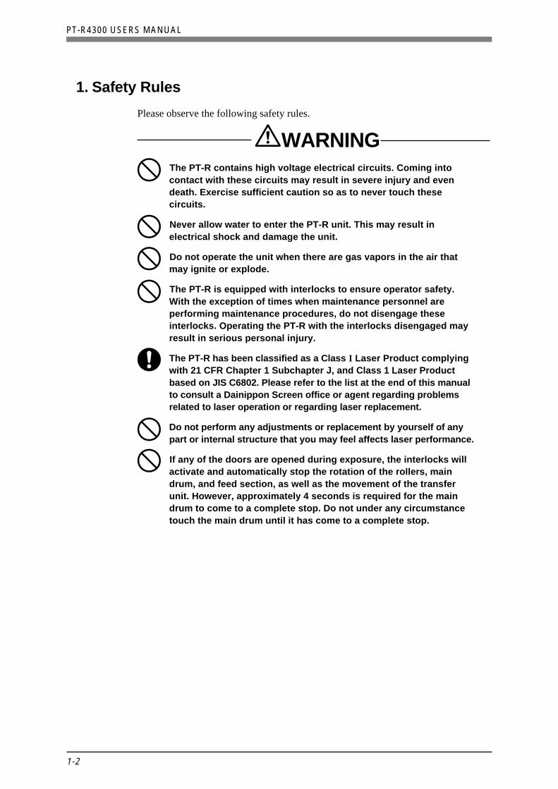
1. Safety Rules
Please observe the following safety rules.
WARNINGThe PT-R contains high voltage electrical circuits. Coming intocontact with these circuits may result in severe injury and evendeath. Exercise sufficient caution so as to never touch thesecircuits.
Never allow water to enter the PT-R unit. This may result inelectrical shock and damage the unit.
Do not operate the unit when there are gas vapors in the air thatmay ignite or explode.
The PT-R is equipped with interlocks to ensure operator safety.With the exception of times when maintenance personnel areperforming maintenance procedures, do not disengage theseinterlocks. Operating the PT-R with the interlocks disengaged mayresult in serious personal injury.
The PT-R has been classified as a Class I Laser Product complyingwith 21 CFR Chapter 1 Subchapter J, and Class 1 Laser Productbased on JIS C6802. Please refer to the list at the end of this manualto consult a Dainippon Screen office or agent regarding problemsrelated to laser operation or regarding laser replacement.
Do not perform any adjustments or replacement by yourself of anypart or internal structure that you may feel affects laser performance.
If any of the doors are opened during exposure, the interlocks willactivate and automatically stop the rotation of the rollers, maindrum, and feed section, as well as the movement of the transferunit. However, approximately 4 seconds is required for the maindrum to come to a complete stop. Do not under any circumstancetouch the main drum until it has come to a complete stop.

1-3
Chapter 1 Ensuring Safety
CAUTIONBefore attaching the plate to the PT-R, verify that no paper orpieces of packaging remain on either side of the plate. The thermallaser may cause paper or packaging to ignite and start a fire in thePT-R.
The edges of the plate are very sharp. When handling the plate, besure to use anti-slip protective gloves. If handled with bare hands,the edges of the plate may cause injury.
Store plates in a place where the height is appropriate for removalwithout hurting your back. Repeated strain to the back can lead tolower back pain.
Do not put your weight on the punch debris receptacle on the backof the PT-R. Doing so could lead to damage to the tray or anaccident resulting from tripping.
CAUTION! Do not cover the PT-R with a cloth or block its air vents in any way.
NOTE Regarding the safety of the PT-R
• Electrical safety
The PT-R has been designed, tested, and evaluated in accordance with IEC950 ofthe “Safety of Information Technology Equipment, Including Electrical BusinessEquipment” electrical safety standards.
• Laser safety
The PT-R has been designed, tested, and evaluated in accordance with thefollowing laser safety standards:
• “U.S. Federal Regulations 21 CFR 1040.10,” which accompany the rules ofthe “Center of Device and Radiological Health (CDRH)” of the U.S. Food andDrug Administration.
• “Safety of Laser Products” of IEC 60825.
“Equipment Classification”
“Requirement”
“User's Guide”

PT-R4300 USERS MANUAL
1-4
2. Precautions Regarding the Electrical System
2.1 Power Supply
WARNINGTo avoid electrical shock accidents from the AC power supply,make sure that the unit is properly grounded in accordance withoperation site regulations. Ground the PT-R separately.
A readily accessible disconnection device (building side powerswitch) must be installed in the fixed building wiring beforeinstalling the PT-R.
Have a qualified electrician select breakers and perform theelectrical work.
Be sure to verify that both the PT-R and building side powerswitches are turned off before connecting the power cables of thePT-R to the switchboard.
CAUTION! • To prevent current overload, install a current breaker at the power supplybefore connecting the PT-R to the power supply.
• Power cables are not provided in countries outside Japan. Please refer toChapter 2 “6. Power Supply and Power Cables,” and obtain appropriatelyrated power cables that conform to the standards of your country orregion.
2.2 Precautions Regarding the Handling of Power Cables and Hoses
WARNINGIf you discover deformations, cracks, or cuts in the surface of apower cable or hose, immediately turn off the power switch, turnthe building side power switches to OFF, and contact your nearestDainippon Screen sales office or agent.
Do not step on or forcefully pull a power cable or hose.
Fig. 1-1 Power cable and hoses

1-5
Chapter 1 Ensuring Safety
2.3 Performing an Emergency Stop
If trouble occurs during operation and you want to stop the PT-R immediately, pressthe forced drum stop switch.When the forced drum stop switch is pressed, it takes approximately 4 seconds forthe drum to stop rotating.
CAUTION! Do not use this switch during normal operation. This switch is only to beused if the drum needs to be stopped in case of an emergency.
Forced drum stop switch
Fig. 1-2 Forced drum stop switch
WARNINGIn order to prevent accidents, be sure to turn off both the PT-R andbuilding side power switches after work or before perforningmaintenance or inspection procedures.
2.4 Handling Power Failures
WARNINGIf a power failure in the external power supply occurs, turn off the PT-Rand building side power switches in order to prevent accidents.
When the power is restored, turn on the building side power switch and turn the PT-Rpower switch ON again. For more details, refer to Chapter 4 “3. Turning the PowerOn and Off.”

PT-R4300 USERS MANUAL
1-6
3. General Precautions
WARNINGDo not turn on the power switch of the PT-R or attempt operationuntil you have read this manual well and understand the contents.
The operator should wear appropriate clothing.
If you discover any abnormality or problem in the PT-R, contactyour nearest Dainippon Screen office or agency to haveappropriate measures taken.
Even in cases where the PT-R is capable of continuous operation,correct unattended operation is not guaranteed. A trained operatorwho is able to handle emergencies and initial safety measures mustbe present during operation in case an abnormal situation occurs.Our company offers courses on the proper handling of ourproducts whenever needed. Please attend a course beforeattempting to operate the PT-R. Application for these courses canbe made at any Dainippon Screen office or agency.
Do not attempt to operate the PT-R when you are not feeling well.
4. Maintenance
WARNINGOnly maintenance personnel who have received the specifiedtraining should perform maintenance work on the PT-R.
The operator should not under any circumstance turn on thebuilding side and PT-R power switches when a maintenancetechnician is performing maintenance work.
Fig. 1-3 Operator clothing
Wear clothing that will not become caught in the machinery.
Long hair is tiedback.
Cuffs are buttoned.
Hands are wet.
Cuffs are open.
A necktie or necklaceis dangling.
Unneeded thingsare carried.
Excessively longpants
Slippers or sandalsWear safety boots

1-7
Chapter 1 Ensuring Safety
5. Warning and Caution Labels
To ensure safety, the following warning and caution labels are attached to parts ofthe PT-R that are potentially dangerous to operators and maintenance personnel.Observe the following safety rules when operating or performing maintenance workon the PT-R.
WARNING• Follow the instructions on all warning/caution labels.
• Do not erase or deface the instructions on a warning or caution label.
• Do not place objects in front of or cover a warning or caution label.
• If a warning or caution label has peeled off or is dirty, replace it with anew label. Failure to replace the label is extremely dangerous.
NOTE If you need a new warning or caution label, consult your nearest Dainippon Screensales office or agent listed at the end of this manual.
Fig. 1-4, 1-5, 1-6 and 1-7 below shows which labels are attached to the PT-R andwhere they are attached. Always follow the instructions on the labels when operatingthe PT-R.
Fig. 1-4 Location of warning and caution labels (1)
This label reminds you toremove the interleaf papaerfrom both sides of the platewhen you set the plate.

PT-R4300 USERS MANUAL
1-8
Fig. 1-5 Location of warning and caution labels (2)
Label indicating that laserradiation exists inside.
AVOID EYE OR SKINEXPOSURE TO DIRECTOR SCATTERED RADIATION
32W MAX CW 808nmCLASS 4 LASER PRODUCT
INVISIBLELASER RADIATION
BESTRAHLUNG VON AUGEODER HAUT DURCHDIREKTE ODER STREUSTRAHLUNGVERMEIDEN !
32W MAX CW 808nmLASER KLASSE 4
UNSICHTBARENLASER-STRAHLUNG
EXPOSITION DANGEREUSEDE L'CEIL OU DE LA PEAUAU RAYONNEMENT DIRECTOU DIFFUS
32W MAX CW 808nmAPPAREIL Á LASER DE CLASSE 4
RAYONNEMENT LASERNON VISIBLE
Label indicating the class, power, and wavelength of the laser
DANGERINVISIBLE LASERRADIATION WHENOPEN AND INTERLOCKSDEFEATED.AVOID EYE OR SKIN EXPOSURE TO DIRECTOR SCATTEREDRADIATION.
VORSICHT!UNSICHTBARELASERSTRAHLEN, WENNGEOFFNET UNDSICHERHEITSSCHALTERDEAKTIVIERT SIND.VERMEIDEN SIE DIREKTEODER INDIREKTEBESTRAHLUNG VONAUGEN UND HAUTI
ATTENTIONRAYONNEMENT LASERNON VISIBLE DANGEREUXEN CAS D’ OUVERTUREET LORSQUE LA SECURITEEST NEUTRALISEE.EVITER UN CONTACTDIRECT OU DIFFUS AVEC L’ OEIL OU LA PEAU.
This label warns you that releasing aninterlock whilean operation door withthis label attached is opened mayexpose you to dangerous invisiblelaser radiation.
Label indication that laserradiation exists inside

1-9
Chapter 1 Ensuring Safety
Label indicating thatthe product meets therequirements for CEmarking.
This device complies with Part 15 of the FCC Rules.
Operation is subject to the following two conditions:
(1) this device may not cause harmful interference, and
(2) this device must accept any interference received,
including interference that may cause undesired
operation.
This Class A digital appartus meets all requirements of the
Canadian interference-Causing Equipment Regulations.
Cet appareil numerique de la Clase A respecte toutes les
exigences du Regiemental sur le material brouilleur du
Canada.
VCCI-1
T
Fig. 1-6 Location of warning and caution labels (3)
Label indicating that laserradiation exists inside.
Label indicating theexistence of a alaser aperturewhere the label is attached.
Label indicating highleakage current.
Label indicating thatthe product complies withFCC rules.

PT-R4300 USERS MANUAL
1-10
Fig. 1-7 Location of warning and caution labels (4)
MODEL NUMBER: PT -R 4 3 0 0
VOLTAGE RATING: 200-240VAC
304 sinkaichi, sayama, kumiyama-cho, kuze-gun, kyoto 613, Japan
THIS PRODUCT CONFORMS TO DHHS REGULATIONS AS APPLICABLE
TO STANDARDS 21 CFR CHAPTER I SUBCHAPTER J
MADE IN JAPAN T
MADE IN JAPAN Z830B-L8
M O D E L
MFG.No.
D A T E
V O L T S
A M P S .
P H A S E Hz kW
A
V
Label indicating thatthis is a Class 1 Laser Product
Label indicating that the productconforms to CDRH regulations.
Label indicating the powerspecifications.
This label is attached nearthe ground terminal to alloweasy identification of theground terminal in the PT-R.
1-11
Chapter 1 Ensuring Safety
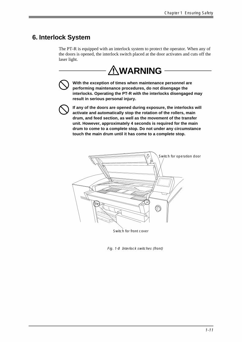
6. Interlock System
The PT-R is equipped with an interlock system to protect the operator. When any ofthe doors is opened, the interlock switch placed at the door activates and cuts off thelaser light.
WARNINGWith the exception of times when maintenance personnel areperforming maintenance procedures, do not disengage theinterlocks. Operating the PT-R with the interlocks disengaged mayresult in serious personal injury.
If any of the doors are opened during exposure, the interlocks willactivate and automatically stop the rotation of the rollers, maindrum, and feed section, as well as the movement of the transferunit. However, approximately 4 seconds is required for the maindrum to come to a complete stop. Do not under any circumstancetouch the main drum until it has come to a complete stop.
Switch for operation door
Switch for front cover
Fig. 1-8 Interlock switches (front)

PT-R4300 USERS MANUAL
1-12
Soft switch fordrum slowdown
Interlock switch for rear cover
Interlock switch forright side cover
Fig. 1-10 Interlock switches (right side)
Interlock switch forleft side cover
Fig. 1-9 Interlock switches (rear)

1-13
Chapter 1 Ensuring Safety
7. Disposal of the PT-R
WARNINGWhen disassembling the PT-R there are dangerous parts such as thegas spring in the open/close part of the operation door. Because ofthe danger present when disassembling the PT-R no one other than aspecialized engineer who was properly trained at Dainippon Screenshould carry this out.
Handling plate and plate punch debris
Please acquire the services of a professional recycling company to take care of usedplates and plate punch debris.
Lithium battery handling
A lithium battery is used in the control panel of the PT-R. Under normal use thelithium battery has a life of five to ten years. When it expires it should be disposed ofcarefully using special procedures for handling harmful substances. When disposingof the PT-R please contact the place of purchase or use the contact information at theend of this manual to request the services of specialized lithium battery removal anddisposal personnel.
Disposal of replacement parts and the PT-R itself
When disposing replacement parts or the PT-R itself, please seek advice from theplace of purchase or the contact information at the end of this manual, or request theservices of a professional disposal company that specializes in recycling.If you have any questions regarding disposal, please consult the place of purchase orcontact the Dainippon Screen sales office or agency listed at the end of this manual.

PT-R4300 USERS MANUAL
1-14
8. Environmental Protection
In March of 2001, Dainippon Screen and all its manufacturing facilities, includingaffiliate companies, acquired ISO14001 Environment Management Systemcertification. Further to this, Dainippon Screen has and still continues to do its bestfor environmental preservation by promoting manufacturing practices that do notharm on the environment.
ISO14001 Environment Management System is an international standard designedto preserve the environment. It places emphasis on the initiative of corporationsand organizations to take responsibility for and to actively engage in activities forthis purpose. In addition to requiring that environmental regulations be observedand that the environmental impact of corporate activities be reduced, it continuallyevolves, in accordance with its unique environmental policy, through theformulation, execution, practical review, and amendment of goals. It efficientlypromotes activities for environmental preservation by getting manufacturersactively involved in environmental issues and also by obtaining the cooperation ofcustomers through information they provide.
The following are requirements regarding product use and disposal for environmentalpreservation. Please read thoroughly and faithfully observe the contents in the samemanner as you would for safety related cautions.
Environmental regulations
Laws, enforcement ordinances, enforcement regulations and bylaws exist that aremeant to protect the environment. Please consult your national, state/province orlocal government for more information about these and the punishments involved.
Handling of waste Iitem(s) for disposal
Please use the services of a professional disposal company according to the followingprocedure.
1. Verify that the item(s) to be disposed of is included in the items approved(type of item, type of business, and conditions of authorization) by the national,state/province or local government for disposal by the company in question.
2. Conclude agreements for commission of authority to collect and transport, andcommission of authority to dispose.
3. Consign the item(s) for disposal and, if necessary, submit a disposal report to yournational, state/provincial or local government.
4. Obtain transport completion and disposal completion documents from the disposalcompany to verify that the disposal was properly completed.
5. Visit the disposal company and verify that the work was conducted properlyaccording to contract.
NOTE

1-15
Chapter 1 Ensuring Safety
Handling of dangerous and toxic waste
The following procedures are required, in addition to the usual handling procedureby disposal companies, for waste such as that which is explosive, poisonous,contagious, or otherwise potentially dangerous to human health or to theenvironment.
• Verify that the disposal company is properly certified by the national, state/provincial or local government to take responsibility for the handling of dangerousand toxic waste.
• Label the item for disposal to indicate what it is and to indicate that it is adangerous and/or toxic waste. Making sure it will be distinguished from otherwaste, request the storage and processing services of the disposal company.
• Submit your official report for disposal of dangerous and toxic wastes by therequired date to the applicable department of your national, state/provincial orlocal government.
Handling of valuable resources
Although materials that can be recycled such as plates (PS plates) do not classify aswaste, they should be treated as industrial waste if they will be disposed of asgarbage.

PT-R4300 USERS MANUAL
1-16 End of Chapter 1

Chapter 2
This chapter explains precautions for installing and moving
the PT-R.
Installing and Movingthe PT-R
2

PT-R4300 USERS MANUAL
2-2
1. Installing and Moving the PT-R4300Installation and moving of the PT-R must be performed by a Dainippon Screenappointed service comapny or service technician. Dainippon Screen bears absolutelyno responsibility for any damage, breakdowns, or malfunctioning resulting frominstallation or moving by anyone other than a Dainippon Screen appointed servicecomapny or service technician, and Dainippon Screen extends no guaranteesregarding safety in such a case. If you need to have the PT-R moved or installed,consult one of the Dainippon Screen offices or agency listed at the end of thismanual.
2. Installation LocationDo not install the PT-R in any of the following locations, as safety problems,failures, and malfunctioning may result.
• Locations directly exposed to sunlight
• Locations where electrical interference (voltage fluctuations or noise) mayoccur
• Locations close to machines that emit strong magnetic fields.
• Locations subject to sudden changes of temperature
• Locations close to sources of heat
• Locations with high temperature or high humidity
• Locations subject to vibration
• Unstable locations where the floor is not level
• Locations with dust
• Location subject to condensation
• Locations where the PT-R might be exposed to chemical solutions, smoke,volatile gases, or corrosive gases.
High temperature, high humidity Vibrations, unstable
Fig. 2-1 Bad installation locations

2-3
Chapter 2 Installing and Moving the PT-R
429
800 1750 1000
107.5
97.5
45
750 750 125
125
200 200
600
200
200
800
1030
1000
655
BlowerCommunication cable (2 m)
Vacuum hose (2 m)to
PT-R4300
Adjuster foot
(Units: mm)
Power cable for blower (2 m)
4
3. Space Required for InstallationTo allow escape in the event of danger and enable access for maintenance, leave atleast 800 mm open around the periphery of the PT-R. Keep the floor free of obstaclesand keep a path to the building side power switch clear.
CAUTION! • Keep 200 mm open around the periphery of the blower to allow heatdissipation.
• A 2-meter vacuum hose is supplied with the PT-R. Do not use a hosedifferent from the hose that is supplied hose, even if you require a hose ofdifferent length. Pressures losses caused by a different hose mayadversely affect the operation of the blower and cause a malfunction.
Fig. 2-2 Installation space

PT-R4300 USERS MANUAL
2-4
4. Load Tolerance of BuildingThe site of installation requires a floor load tolerance of at least 4010 N/m2 (410 kgf/m2) . To prevent the formation of cracks in the floor, it is recommended that theadjuster foot of the PT-R rest on the framework of the building; however, the load onthe floor will vary depending on the strength of the floor, the position of theframework, the positioning of the PT-R, and the presence of other heavy objects inthe same location. Consult with the designer of the building or other authority.
5. Ground Connections• In order to prevent electrical shock accidents from the AC power supply, perform
grounding connections for the machine only after making sure that the PT-R powerswitch and the building side power switch are both off.
• Since the leakage current of the PT-R is max. 3.5 mA, be sure to conduct groundingbefore connecting the power line of the PT-R 3-line cable.
Have a qualified electrician select the above items and perform the connections.
6. Power Supply and Power Cables• Have electrical work performed by a qualified electrician.
• Make arrangements to obtain the power supply indicated in Chapter 9, “TechnicalInformation.”
• PT-R power is supplied independently from the building side power switch,therefore do not connect other devices to that power switch.
• The allowed range of voltage fluctuation in 200 V-240 V power supply areas is+6%, -10%. If fluctuations in the power supply are greater than this, use astabilizer.
• A power cable is not provided with products sold outside of Japan. For the PT-R,please obtain an 2.5 mm2 × 3-wire power supply cable that complies with thestandards of your country and is rated at 300 V AC or higher.If the cable described above does not comply to the standards of the country ofinstallation, please refer to the power supply nameplate attached to the PT-R andprovide a cable locally that does comply.
CAUTION! A readily accessible disconnection device (building side power switch)must be installed in the fixed building wiring before installing the PT-R.
End of Chapter 2

Chapter 3
Names of Each Part
3
This chapter gives an overview of the PT-R and explains its
configuration.

PT-R4300 USERS MANUAL
3-2
1. The PT-R4300
Fig. 3-1 Plate transport section
Fig. 3-2 Full view (front and left sides)
Operation door
Ejection table
Positioning labels (for large-sized plate)Insertion table
Transport roller
Positioning labels(for small-sized plate)
External cover filter
Operation doorOperation panel
Front cover
Power switch

3-3
Chapter 3 Names of Each Part
Fig. 3-3 Full view (rear and right sides)
Fig. 3-4 External cover filter
Punch debris outlet
Peripheraldeviceconnectors
Rear cover
Attachment hooks for punchdebris receptacle
Power cable connector
Vacuum hoseconnector
Exposed plate fromthe rear outlet
External fan
Protrusions
External cover
External cover filter
Rectangular holes
Forced drum stop switch

PT-R4300 USERS MANUAL
3-4
Fig. 3-5 Peripheral device connectors
F-PIF connector (25-pin)
F-PIF connector (50-pin)Service connector(RS-232C, 9-pin)
Developer unitconnector(25-pin)
Blower controlconnector (14-pin)
Power supply connectorfor blower

3-5
Chapter 3 Names of Each Part
Fig. 3-6 Inside of front cover
Fig. 3-7 Inside of rear cover
Drum
Optics unit
Front cover attachment hooks
Rear cover attachment hook
Drum
Cleaning roller
Rear cover attachment hook
Punching unit (standard)

PT-R4300 USERS MANUAL
3-6
2. AccessoriesThe following accessories are provided with the PT-R.
2.1 Standard Accessories
Blower unit
Blower unitVacuum hose (2 m)Communication cable (UL2464 AWG24 × 7P, 2 m)Power cable (0.75 mm2 × 3 wires 300V) for blower unit which plugs into PT-R(2 m)
Punch debris receptacle
Power cable
Vacuum hose
Communication cable
Blower unit

3-7
Chapter 3 Names of Each Part
Users Manual
2.2 Optional Accessories
The following items are available as options. For more information or to place anorder, contact one of the Dainippon Screen offices or agents listed at the end of thismanual.
Punch unit (types: Dainippon Screen, Bacher, Protocol, Komori, others)
Cassette auto loader (single, multi)

PT-R4300 USERS MANUAL
3-8 End of Chapter 3

This chapter explains the basic procedures for operating the
PT-R.
Chapter 4
Basic Operation 4

PT-R4300 USERS MANUAL
4-2
1. OverviewThe general procedure for operating the PT-R is explained here. For detailedoperating procedures, refer to the appropriate section.
1. Verify that all doors and covers are closed. Turn on the power switch of theperipheral devices first, and then the power switch of the PT-R. For more details,refer to “3.1 Turning On the Power.” A memory check of the PT-R begins.When the memory check ends, the initial screen appears on the display.
Fig. 4-1 Initial screen
2. Press [START] . Initialization of the PT-R begins.When initialization ends, the online (Ready) screen appears.
Fig. 4-2 Online (Ready) screen
3. Press [OFFLINE] . The display changes to the offline screen.
Fig. 4-3 Offline screen
START
Please press [START].
Ready
1: Plate 1
OFFLINE OPEN
OK NEXTONLINE
Set printing machine
Set plate
Set media type
Set exposure mode
User maintenance

4-3
Chapter 4 Basic Operation
OK
Press [Open] button to open door.No. 1 A4-8page
Set plate listed above.
CANCEL OPEN
Press [Open] button to open door.No. 1 A4-8page
Set plate listed above.
4. Based on the plate to be used, set the proper parameters in “Printing machineinformation settings,” “Plate settings,” and “Media type settings.” For moredetails, refer to Chapter 5 “User Menu.”
5. Press [ONLINE] to return to the online screen.
6. Initiate output from the host computer.The following screen appears on the operation panel of the PT-R and the buzzerbeeps repeatedly.
Fig. 4-4 Plate set request screen
7. Press [OK] . The buzzer stops and the following screen appears.
Fig. 4-5 Operation door open screen
8. Press [OPEN] . The lock is released and the operation door slightly opens, andset the specified plate. For more details, refer to “8. Online Mode.”
9. Close the operation door to start loading. When loading ends, exposure begins.When exposure ends, the plate is ejected to the ejection table and the operationdoor opens.
10. Transfer the ejected plate to the online processor.
11. When you are finished, turn off the power switch of the PT-R first, and then thepower switch of the peripheral devices. For more details, refer to “3.2 TurningOff the Power.”

PT-R4300 USERS MANUAL
4-4
2. Connecting the CablesVerify that all power to the system and host computer is off, and then make sure thatthe cables are connected correctly. The following diagram shows the cablesconnected to the PT-R and where they are connected. The cables to be connected arethe two PIF cables. (The power cable and communication cable for blower controlwere connected during installation.) The PIF cable connects the PT-R to the hostcomputer.
F-PIF connector-2 (25 pin)
F-PIF connector-1 (50 pin)
PIF cable 1
To hostcomputer
To blower
Communication cableconnectorfor blower control
PIF cable 2
Power cable connectorfor blower control
Fig. 4-6 Cable connectors