Embed Size (px)
Citation preview

48HC with ComfortLINK Controls48LC with ComfortLINK or Electro---Mechanical ControlsSingle--Package Rooftop Unit (RTU)Gas Heating/Electric Cooling Units3 to 25 Nominal Tonswith Puronr (R--410A) Refrigerant
User’s Information Manual
NOTE: Read the entire instruction manual before startingthe installation.
ELECTRICAL SHOCK, FIRE OR EXPLOSIONHAZARD
Failure to follow safety warnings exactly could resultin dangerous operation, serious injury, death orproperty damage.
Improper servicing could result in dangerousoperation, serious injury, death or property damage.
S Before servicing, disconnect all electrical power tothe unit.
S When servicing controls, label all wires prior todisconnecting. Reconnect wires correctly.
S Verify proper operation after servicing.
! WARNING
NOTE TO INSTALLER:This manual should be left with the equipment owner.
TABLE OF CONTENTSPAGE
SAFETY CONSIDERATIONS 1. . . . . . . . . . . . . . . . . . . .
TO LIGHT UNIT WITHELECTRO--MECHANICAL CONTROL 3. . . . . . . . . . . .
TO LIGHT UNIT WITHCOMFORTLINK CONTROL 5. . . . . . . . . . . . . . . . . . . . .
TO SHUT OFF UNIT WITHELECTRO--MECHANICAL CONTROL 7. . . . . . . . . . . .
TO SHUT OFF UNIT WITHCOMFORTLINK CONTROL 8. . . . . . . . . . . . . . . . . . . . .
ROUTINE MAINTENANCE & CAREFOR THE EQUIPMENT OWNER 9. . . . . . . . . . . . . . . . .
REGULAR DEALER MAINTENANCE 11. . . . . . . . . . .
BEFORE YOU CALL FOR SERVICE 12. . . . . . . . . . . .
SAFETY CONSIDERATIONS
Improper installation, adjustment, alteration, service,maintenance, or use can cause fire, electrical shock, orother conditions which may cause personal injury orproperty damage. Consult a qualified installer, serviceagency or your distributor or branch for information orassistance. The qualified installer or agency must usefactory--authorized kits or accessories when modifyingthis product. Refer to the individual instructions packagedwith the kits or accessories when installing.
Follow all safety codes and wear safety glasses. Have fireextinguisher available. Read these instructions thoroughlyand follow all warnings or cautions attached to the unit.Consult local and state building codes and Sheet Metaland Air Conditioning National Association (SMACNA)for special installation requirements.
Recognize safety information. This is the safety--alertsymbol . When you see this symbol on the unit or ininstructions and manuals, be alert to the potential forpersonal injury. Understand the signal words DANGER,WARNING, and CAUTION. These words are used withthe safety--alert symbol. DANGER identifies the mostserious hazards, which will result in severe personal injuryor death. WARNING signifies hazards, which could resultin personal injury or death. CAUTION is used to identifyunsafe practices, which may result in minor personalinjury or product and property damage. NOTE is used tohighlight suggestions which will result in enhancedinstallation, reliability, or operation.
Should the gas supply fail to shut off or if overheatingoccurs, shut off the gas valve to the furnace (see Figs. 2through 4) before shutting off the electrical supply.

2
FIRE, EXPLOSION HAZARD
Failure to follow this warning could result in personalinjury or death.
What to do if you smell gas:
S Leave the building.
S Do not try to light any appliance.
S Do not touch any electrical switch; do not use anyphone in your building.
S Immediately call your gas supplier from a neighbor’sphone. Follow the gas supplier’s instructions.
S If you cannot reach your gas supplier, call the firedepartment.
Installation and service must be performed by aqualified installer, service agency or the gas supplier.
! WARNING
FIRE, EXPLOSION HAZARD
Failure to follow this warning could result in personalinjury, death and/or property damage.
Do not store or use gasoline or other flammable vaporsand liquids in the vicinity of this or any other appliance.
! WARNING
ELECTRICAL SHOCK HAZARD
Failure to follow this warning could result in personalinjury, death and/or property damage.
Before performing maintenance, be sure main powerswitch to unit is turned off and lockout tag is installed.There may be more than one power switch.
! WARNING
ELECTRICAL OPERATION HAZARD
Failure to follow this warning could result in personalinjury, death and/or property damage.
Do not use this equipment if any part has been underwater. A flood--damaged equipment is extremelydangerous. Attempts to use the equipment can resultin fire or explosion. A qualified service agency shouldbe contacted to inspect the equipment and to replaceall gas controls, control system parts, electrical partsthat have been wet or the equipment if deemednecessary.
! WARNING
Your rooftop heating/cooling unit is equipped with anautomatic, direct spark ignitor and an induced--draft,combustion blower.
PERSONAL INJURY HAZARD
Failure to follow this warning could result in personalinjury, death and/or property damage.
Burners will light automatically. Do not attempt tolight by hand.
! WARNING
CUT HAZARD
Failure to follow this caution may result in personalinjury.
When removing access panels or performingmaintenance functions inside your unit, be aware ofsharp sheet metal parts and screws. Although specialcare has been taken to reduce sharp edges inside theunit, be extremely careful when handling parts orreaching into the unit.
CAUTION!
IMPORTANT FACTS
S DO: READ AND UNDERSTAND THIS MANUAL.
S DO: Have your equipment and vent system inspectedannually by a qualified service technician.
S DO: Inspect your filter monthly and clean or replacewhen needed.
S DO: Provide adequate airflow to the equipment forefficient combustion and safe ventilation.
S DO Make sure:
1. All flue and vent connections are clear and free ofobstructions, are leak free, and not damaged.
2. Duct connections are leak free and physically sound.3. The unit base support is free of cracks, gaps, etc.4. There are no signs of furnace deterioration.5. Burners are aligned correctly.6. Follow routine maintenance inspection.
S DO NOT: Keep combustible materials, gasoline, and otherflammable liquids or vapors around your equipment.
S DO NOT: Cover your equipment in any manner.
S DO NOT: Store anything (including trash or debris)near your equipment.
S DO NOT: In any way block or restrict airflow aroundyour equipment.
S DO NOT: Contaminate the air used for combustion ofyour equipment with any kind of chemical or fumes. This
could also cause heat exchangers, metal vent systems orcomponents to deteriorate.

3
DETERMINE TYPE OF UNIT CONTROLThe procedures used to light or shut off the unit depend onthe type of unit control. This section will help determinethe control type of the unit.
Electro--Mechanical ControlThese units may be controlled directly by a thermostat, orindirectly by a third--party control that connects to thethermostat inputs. For direct thermostat control, use theElectro--Mechanical Control procedures in this book. Forunits with third--party controls connected to the thermostatinputs, refer to the third--party control instructions (notincluded) for procedures to ensure complete unit shut off.
ComfortLINK ControlThese units have a factory--installed Carrier ComfortLINKcontrol. A Scrolling Marquee display is located in the unitcontrol box behind the control box access panel. These unitsmay be controlled directly by a thermostat, directly by a spacetemperature sensor, or indirectly through other Carrier ComfortNetworkr (CCN) communication devices. To ensure completeunit shut off, use the ComfortLink Control procedures in thisbook.
TO LIGHT UNIT WITHELECTRO--MECHANICAL CONTROL
FIRE, EXPLOSION HAZARD
Failure to follow this warning could result in personalinjury, death and/or property damage.
1. Do not turn off the electrical power to unitwithout first turning off the gas supply.
2. Before attempting to start the gas heating section,familiarize yourself with all the procedures thatmust be followed.
3. Never attempt to manually light the burners onthe unit with a match, lighter, or any other flame.If the electric sparking device fails to light theburners, refer to the shutdown procedures, thencall your dealer as soon as possible.
! WARNING
Step 1 — Set room thermostat/unit controller to thelowest temperature setting and set the SYSTEMswitch to HEAT or AUTO position. See Fig. 1.
®
C09296
Fig. 1 -- Thermostat/Unit Controller
Step 2 — Turn off the gas supply by closing the gassupply shut--off valve (external to RTU unit). See Fig. 2and 3 (depending on the size of the unit) for locations.
Gas Supply Shut Off Valve (Field Supplied)
C07358
Fig. 2 -- Gas Supply Shut--Off Valve Location3 to 12.5 Ton Units (Thru the base gas supply shown.)
Gas Supply Shut Off Valve(Field Supplied)
C08485
Fig. 3 -- Gas Supply Shut--Off Valve Location15 to 25 Ton Units
C07330
Fig. 4 -- Gas Supply Shut Off Valve
Step 3 — Turn off the electrical supply to the unit byswitching the RTU main disconnect to OFF. Then,ensure personal safety by installing a lockout tag onthe disconnect.
LOCK-OUTTAG
ON
OFF
MAIN
C07331
Fig. 5 -- RTU Main Disconnect -- Electrical Supply
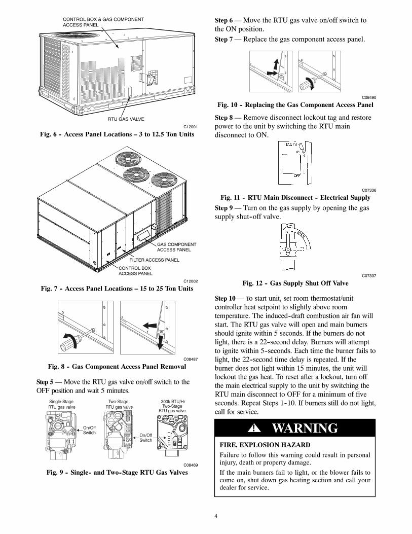
Step 4 — Remove the gas component access panel.For location of the gas component access panel, seeFig. 6 and 7 (depending on the size of the unit).
4
RTU GAS VALVE
CONTROL BOX & GAS COMPONENTACCESS PANEL
C12001
Fig. 6 -- Access Panel Locations – 3 to 12.5 Ton Units
FILTER ACCESS PANEL
GAS COMPONENTACCESS PANEL
CONTROL BOXACCESS PANEL
C12002
Fig. 7 -- Access Panel Locations – 15 to 25 Ton Units
C08487
Fig. 8 -- Gas Component Access Panel Removal
Step 5 — Move the RTU gas valve on/off switch to theOFF position and wait 5 minutes.
Two-StageRTU gas valve
300k BTU/HrTwo-Stage
RTU gas valve
On/OffSwitch
OFF
ON
Single-StageRTU gas valve
On/OffSwitch
C08469
Fig. 9 -- Single-- and Two--Stage RTU Gas Valves
Step 6 — Move the RTU gas valve on/off switch tothe ON position.Step 7 — Replace the gas component access panel.
C08490
Fig. 10 -- Replacing the Gas Component Access Panel
Step 8 — Remove disconnect lockout tag and restorepower to the unit by switching the RTU maindisconnect to ON.
C07336
Fig. 11 -- RTU Main Disconnect -- Electrical Supply
Step 9 — Turn on the gas supply by opening the gassupply shut--off valve.
C07337
Fig. 12 -- Gas Supply Shut Off Valve
Step 10 — To start unit, set room thermostat/unitcontroller heat setpoint to slightly above roomtemperature. The induced--draft combustion air fan willstart. The RTU gas valve will open and main burnersshould ignite within 5 seconds. If the burners do notlight, there is a 22--second delay. Burners will attemptto ignite within 5--seconds. Each time the burner fails tolight, the 22--second time delay is repeated. If theburner does not light within 15 minutes, the unit willlockout the gas heat. To reset after a lockout, turn offthe main electrical supply to the unit by switching theRTU main disconnect to OFF for a minimum of fiveseconds. Repeat Steps 1--10. If burners still do not light,call for service.
FIRE, EXPLOSION HAZARD
Failure to follow this warning could result in personalinjury, death or property damage.
If the main burners fail to light, or the blower fails tocome on, shut down gas heating section and call yourdealer for service.
! WARNING

5
Step 11 — Set the room thermostat/unit controllerheating setpoint to desired temperature setting.
TO LIGHT UNIT WITHCOMFORTLINK CONTROL
FIRE, EXPLOSION HAZARD
Failure to follow this warning could result in personalinjury, death and/or property damage.
1. Do not turn off the electrical power to unitwithout first turning off the gas supply.
2. Before attempting to start the gas heating section,familiarize yourself with all the procedures thatmust be followed.
3. Never attempt to manually light the burners onthe unit with a match, lighter, or any other flame.If the electric sparking device fails to light theburners, refer to the shutdown procedures, thencall your dealer as soon as possible.
! WARNING
Step 1 — Turn off the unit demand for cooling orheating by using the Scrolling Marquee (see Fig. 13),located in the unit’s control box. See Figs. 14 and 15(depending on size of unit) for control box location.
a. Remove the Control Box access panel from theunit and locate the Scrolling Marquee.
b. Push the ESCAPE key until a blank displayscreen is shown.
c. Push the DOWN arrow key until the SERVICETEST LED is lit.
d. Push the ENTER key. The display will showTEST.
e. Push the ENTER key again. The NO/YES dis-play will flash.
f. Push the UP or DOWN key to toggle the displayto YES and then push ENTER. The unit will belocked off from heat, cooling or any operation.The controls will still function and the displaywill still operate.
NOTE: A password may be required to change ServiceTest values depending on the previous settings configuredin the unit. The default password is “1111.”
Run Status
Service Test
Temperature
Pressures
Setpoints
Inputs
Outputs
Configuration
Time Clock
Operating Modes
Alarms
Alarm Status
ENTER
MODE
ESCAPE
C06320
Fig. 13 -- ComfortLINK Controller
RTU GAS VALVE
CONTROL BOX & GAS COMPONENTACCESS PANEL
C12001
Fig. 14 -- Access Panel Locations – 3 to 12.5 Ton Units
FILTER ACCESS PANEL
GAS COMPONENTACCESS PANEL
CONTROL BOXACCESS PANEL
C12002
Fig. 15 -- Access Panel Locations – 15 to 25 Ton Units
Step 2 — Turn off the gas supply by closing the gassupply shut--off valve (external to RTU unit). See Fig.16 and 17 (depending on the size of the unit) forlocations.
Gas Supply Shut Off Valve (Field Supplied)
C07358
Fig. 16 -- Gas Supply Shut--Off Valve Location3 to 12.5 Ton Units (Thru the base gas supply shown.)

6
Gas Supply Shut Off Valve(Field Supplied)
C08485
Fig. 17 -- Gas Supply Shut--Off Valve Location15 to 25 Ton Units
C07330
Fig. 18 -- Gas Supply Shut Off Valve
Step 3 — Turn off the electrical supply to the unit byswitching the RTU main disconnect to OFF. Then,ensure personal safety by installing a lockout tag onthe disconnect.
LOCK-OUTTAG
ON
OFF
MAIN
C07331
Fig. 19 -- RTU Main Disconnect -- Electrical Supply
Step 4 — On 15 to 25 ton units, remove the GasComponent access panel. For location of the gascomponent access panel, see Fig. 20.
FILTER ACCESS PANEL
GAS COMPONENTACCESS PANEL
CONTROL BOXACCESS PANEL
C12002
Fig. 20 -- Gas Component Access Panel15 to 25 Ton Units
NOTE: On 3 to 12.5 ton units the Gas Component and ControlBox areas are accessed through the same panel (see Fig. 14).
C08487
Fig. 21 -- Gas Component Access Panel Removal
Step 5 — Move the RTU gas valve on/off switch to theOFF position and wait 5 minutes.
Two-StageRTU gas valve
300k BTU/HrTwo-Stage
RTU gas valve
On/OffSwitch
OFF
ON
Single-StageRTU gas valve
On/OffSwitch
C08469
Fig. 22 -- Single-- and Two--Stage RTU Gas Valves
Step 6 — Move the RTU gas valve on/off switch tothe ON position.Step 7 — Replace the gas component access panel.
C08490
Fig. 23 -- Replacing the Gas Component Access Panel
Step 8 — Remove disconnect lockout tag and restorepower to the unit by switching the RTU maindisconnect to ON.
C07336
Fig. 24 -- RTU Main Disconnect -- Electrical Supply
NOTE: Normal operation will automatically begin. ServiceTest mode will automatically end (exit) after a recycle ofpower.

7
Step 9 — Open the gas supply shut--off valve locatedoutside the unit.
C07337
Fig. 25 -- Gas Supply Shut Off Valve
Step 10 — Using the Scrolling Marquee, enable theunit to run using the following procedure:
a. Push the ESCAPE key until a blank displayscreen is shown.
b. Push the DOWN arrow key until the SERVICETEST LED is lit.
c. Push the ENTER key. The display will showTEST.
d. Push the ENTER key again. The NO/YES dis-play will flash.
e. Push the UP or DOWN key to toggle the displayto NO and then push ENTER. The unit will re-turn to normal operation and exit SERVICETEST mode.
Step 11 — To test the operation of the gas section, usethe Scrolling Marquee test routine to energize the gasoutputs and to turn on the gas.Step 12 — For normal operation, make sure that theset points are at the normal heat set points and theScrolling Marquee is not in test mode.
FIRE, EXPLOSION HAZARD
Failure to follow this warning could result in personalinjury, death or property damage.
If the main burners fail to light, or the blower fails tocome on, shut down gas heating section and call yourdealer for service.
! WARNING
TO SHUT UNIT OFF UNIT WITHELECTRO--MECHANICAL CONTROL
FIRE, EXPLOSION HAZARD
Failure to follow this warning could result in personalinjury, death and/or property damage.
1. Turn off gas supply by closing the gas line supplyvalve. Then, turn off the electrical power supply to theunit by switching the disconnect to off. Install lockouttag before servicing or performing maintenance.
2. Do not turn off the electrical power to unitwithout first turning off the gas supply.
! WARNING
Should overheating occur, or the gas supply fail to shutoff, shut off the gas valve in the unit (by moving on/offswitch to off) before shutting off the electrical supply.
Step 1 — Set room thermostat/unit controller heatsetpoint to the lowest temperature setting and set theSYSTEM switch to OFF.
®
C09296
Fig. 26 -- Thermostat/Unit Controller
Step 2 — Turn off gas supply by closing the gas supplyshut--off valve (external to RTU unit). See Fig. 16 and17 (depending on the size of the unit) for locations.
C07330
Fig. 27 -- Gas Supply Shut Off Valve
Step 3 — Turn off the electrical supply to the unit byswitching the RTU main disconnect to off. Then, ensurepersonal safety by installing a lockout tag on thedisconnect.
LOCK-OUTTAG
ON
OFF
MAIN
C07331
Fig. 28 -- RTU Main Disconnect -- Electrical Supply
Step 4 — Remove the gas component access panel. SeeFig. 16 and 17 (depending on the size of the unit) forlocations.
C08487
Fig. 29 -- Gas Component Access Panel Removal

8
Step 5 — Move the RTU gas valve on/off switch tothe OFF position and wait 5 minutes.
Two-StageRTU gas valve
300k BTU/HrTwo-Stage
RTU gas valve
On/OffSwitch
OFF
ON
Single-StageRTU gas valve
On/OffSwitch
C08469
Fig. 30 -- Single-- and Two--Stage Gas Valves
Step 6 — Replace the gas component access panel.
C08490
Fig. 31 -- Replacing the Gas Component Access Panel
Step 7 — If the unit is being shut down because of amalfunction, contact your dealer as soon as possible.DO NOT proceed to step 8.Step 8 — If the unit is being shut down because theheating season has ended, remove the disconnectlockout tag and restore electrical power to the unit byswitching the RTU main disconnect to ON and then setthermostat/unit controller to the COOL position toensure operation of the cooling system during thecooling season.
C07336
Fig. 32 -- RTU Main Disconnect -- Electrical Supply
TO SHUT UNIT OFF UNIT WITHCOMFORTLINK CONTROL
FIRE, EXPLOSION HAZARD
Failure to follow this warning could result in personalinjury, death and/or property damage.
1. Turn off gas supply by closing the gas line supplyvalve. Then, turn off the electrical power supply to theunit by switching the disconnect to off. Install lockouttag before servicing or performing maintenance.
2. Do not turn off the electrical power to unitwithout first turning off the gas supply.
! WARNING
Should overheating occur, or the gas supply fail to shutoff, shut off the gas valve in the unit (by moving on/offswitch to off) before shutting off the electrical supply.
Step 1 — Turn off the unit demand for cooling orheating by using the Scrolling Marquee (see Fig. 33),located in the unit’s control box. See Figs. 14 and 15(depending on size of unit) for control box location.
a. Remove the Control Box access panel from theunit and locate the Scrolling Marquee.
b. Push the DOWN arrow key until the SERVICETEST LED is lit.
c. Push the ENTER key. The display will showTEST.
d. Push the ENTER key again. The NO/YES dis-play will flash.
e. Push the UP or DOWN key to toggle the displayto YES and then push ENTER. The unit will belocked off from heat, cooling or any operation.The controls will still function and the displaywill still operate.
NOTE: A password may be required to change ServiceTest values depending on the previous settings configuredin the unit. The default password is “1111.”
Run Status
Service Test
Temperature
Pressures
Setpoints
Inputs
Outputs
Configuration
Time Clock
Operating Modes
Alarms
Alarm Status
ENTER
MODE
ESCAPE
C06320
Fig. 33 -- ComfortLINK Controller
Step 2 — Turn off gas supply by closing the gassupply shut--off valve (external to RTU unit). See Fig.3 for location.

9
C07330
Fig. 34 -- Gas Supply Shut Off Valve
Step 3 — Turn off the electrical supply to the unit byswitching the RTU main disconnect to off. Then,ensure personal safety by installing a lockout tag onthe disconnect.
LOCK-OUTTAG
ON
OFF
MAIN
C07331
Fig. 35 -- RTU Main Disconnect -- Electrical Supply
Step 4 — Remove the gas component access panel. Forlocation of the gas component access panel, see Fig. 7.
C08487
Fig. 36 -- Gas Component Access Panel Removal
Step 5 — Move the RTU gas valve on/off switch tothe OFF position and wait 5 minutes.
Two-StageRTU gas valve
300k BTU/HrTwo-Stage
RTU gas valve
On/OffSwitch
OFF
ON
Single-StageRTU gas valve
On/OffSwitch
C08469
Fig. 37 -- Single-- and Two--Stage Gas Valves
Step 6 — Replace the gas component access panel.
C08490
Fig. 38 -- Replacing the Gas Component Access Panel
Step 7 — If the unit is being shut down because of amalfunction, contact your dealer as soon as possible.DO NOT proceed to step 8.Step 8 — If the unit is being shut down because theheating season has ended, remove the disconnectlockout tag and restore electrical power to the unitand take control out of Service Test mode to ensureoperation of the cooling system during the coolingseason.
C07336
Fig. 39 -- RTU Main Disconnect -- Electrical Supply
ROUTINE MAINTENANCE & CAREFOR THE EQUIPMENT OWNER
While some maintenance can be performed by laymen,most should be performed by skilled, experiencedpersonnel. Follow the recommended service maintenanceschedule, and modify it as necessary for yourapplication/environment. For instance, dusty areas mayrequire more frequent filter changes.
After performing any maintenance or service on the unit,be sure all panels are securely fastened in place to preventrain from entering unit cabinet and to prevent disruptionof the correct unit airflow pattern.
FIRE AND EQUIPMENT DAMAGE HAZARD
Failure to follow this warning could result in personalinjury and damage to equipment.
Do not use this unit if any part has been under water.Immediately call a qualified service technician toinspect the unit and to replace any part of the controlsystem and gas control that has been under water.
! WARNING
To ensure proper functioning of the unit, flow ofcombustion and ventilating air must not be obstructedfrom reaching the unit. Follow service and performanceclearances as listed in the product data.
Consider the following information before maintaining orservicing equipment:
Compressor
All compressors are factory supplied with a normal chargeof the correct type refrigeration--grade oil in them andshould not require additional oil.

10
Indoor Air Filter(s)
FIRE AND EQUIPMENT DAMAGE HAZARD
Failure to follow this warning could result in personalinjury and damage to equipment.
Never operate unit without filters in place. Theaccumulation of dirt, dust or lint on the internal partsof your unit can cause fire or a loss of efficiency.Damage to the blower motor and/or compressorscould also result.
! WARNING
Indoor air filter(s) should be checked every 3 or 4 weeks(application dependant) and changed or cleaned whennecessary. See Figs. 40 and 41 (depending on size of unit)for air filter access panel location. See Table 1 forreplacement filter dimensions.
S Remove the screws securing the filter access panel.
S While holding filters, tilt upper filter rack.
S Remove filters by pulling up and out toward you from
the track.
S Inspect filters. Clean or replace as necessary.
S Follow direction of airflow arrows as noted on filterframe when returning filters to rack.
S Reinstall air filter access panel.
If you have difficulty in locating your air filter or if youhave questions concerning proper filter maintenance,contact your dealer for instructions. When replacing yourunit filters, always use the same size and type of filter thatwas originally supplied by the installer.
AIR FILTER ACCESS PANEL
C07359
Fig. 40 -- Air Filter Access Panel — 3 to 12.5 ton units
FILTER ACCESSPANEL
GAS COMPONENTACCESS PANEL
CO8486
Fig. 41 -- Air Filter Access Panel — 15 to 25 Ton Units
Table 1 – Replacement Filters -- Size and Quantity
Size Capacity 48HC/48LC04 3 tons 16 x 25 (2)05 4 tons
16 x 16 (4)06 5 tons07 6 tons 16 x 20 (4)08 7.5 tons
20 x 20 (4)09 8.5 tons12 10 tons14 12.5 tons 18 x 24 (6)17 15 tons
20 x 25 (6)20 17.5 tons24 20 tons
16 x 25 (9)28 25 tons
NOTE: Filter sizes in Table 1 are in inches. Numbers in ( )denote filter quantity.
Units with outdoor air capability have a cleanable filterfor the outdoor air. This filter should be checkedsemi--annually and cleaned as necessary with steam or hotwater and a mild detergent. Do not use throwaway filtersin place of cleanable filters.
Condenser Fan
PERSONAL INJURY HAZARD
Failure to follow this warning could result in personalinjury.
Do not poke sticks, screwdrivers, or other object intorevolving fan blades.
! WARNING

11
Electrical Controls and Wiring
Ensure wires do not contact refrigerant tubing or sharpedges. Electrical controls are difficult to check withoutproper instrumentation. If inadequate cooling is suspected,contact your qualified local dealer for service.
Combustion Area and Vent System
The combustion area and vent system should be visuallyinspected before each heating season.
FIRE HAZARD
Failure to follow this warning could result in personalinjury equipment damage.
If your unit makes any unusual or especially loudnoises during heating, shut down the heating sectionand call your qualified service technician.
! WARNING
Proceed as follows to inspect the combustion area andpower--venting system of your unit.
S Turn off gas supply to your unit.
S Turn off electrical power to your unit; install lockout tag.
S Remove gas component access panel.
S Using a flashlight, carefully inspect the burner areas for
dirt, soot, or scale.
EQUIPMENT DAMAGE HAZARD
Failure to follow this caution may result in damage toequipment.
If dirt, soot, rust or scale accumulations are found, callyour service technician and do not operate yourheating section.
CAUTION!
S When you have completed your inspection, follow thestart--up procedures in this manual to restore your unitto operation.
PERSONAL INJURY HAZARD
Failure to follow this warning could result in personalinjury.
Components in heat section may be hot after unit hasbeen started up. When observing flame, be careful notto get close to or touch heating components.
! WARNING
S Observe unit heating operation. Watch the burner flameto see if it is bright blue. If you observe a suspectedmalfunction or that the burner flame is not bright blue,shut down the unit and call your dealer.
S Replace gas component access panel.
Integrated Gas Controller (IGC)
The IGC board incorporates an LED that emits a flashinglight to indicate an alarm code. If the furnace section willnot operate and the LED is flashing a code (1 to 9 flashesin succession), contact your dealer and request service.
NOTE: Make note of the flash code before powering offthe unit. The alarm codes clear after power cycle.
Unit Panels
After performing any maintenance or service on the unit,be sure all panels are securely fastened in place to preventrain from entering unit cabinet and to prevent disruptionof the correct unit airflow pattern.
REGULAR DEALER MAINTENANCE
Heat ExchangerNOTE: To ensure dependable and efficient heatingoperation, the heat exchanger should be checked by aqualified maintenance person before each heating season,and cleaned when necessary.
EQUIPMENT DAMAGE HAZARD
Failure to follow this caution may result in damage toequipment.
This checkout should not be attempted by anyone nothaving the required expertise and equipment to do thejob properly.
CAUTION!
Checking and/or cleaning the heat exchanger involvesremoving the gas controls assembly and the flue collectorbox cover. When finished, the gas controls must bereinstalled for proper operation. Also, the flue collectorbox cover must be replaced correctly, with “red” RTV, sothat a proper seal is maintained. Contact your dealer forthe required periodic maintenance. At the beginning ofeach cooling/heating season and as conditions require.
Fans and Belts, and Fan Motor
Check quarterly the condition of fan wheels and housings,belt tension and fan motor shaft bearings. No lubrication ofcondenser or evaporator fan bearings or motors is required orrecommended.
Evaporator and Condenser Coils
Cleaning of the coils should be done by qualified servicepersonnel. This procedure should be performed prior to coolingoperation or more frequently should conditions require.Contact you dealer for the required annual maintenance.
Condensate Drain
The drain pan and condensate drain line should bechecked and cleaned at the same time the cooling coils arechecked by your dealer.

12
In addition to the type of routine maintenance you might bewilling to perform, your unit should be inspected regularlyby a properly trained and qualified service technician. Aninspection (preferably each heating/cooling season, but atleast every year) should include the following:
S Inspection of all flue product passages, including theburners, heat exchanger, and flue collector box.
S Inspection of all combustion-- and ventilation--airpassages and openings.
S Close inspection of all gas pipes leading to and insideyour unit.
S Inspection and if required, cleaning of the condenser
and evaporator coils.
S Inspection, and if required, cleaning of the condensatedrain pan.
S Inspection and cleaning of blower wheel housing andmotor.
S Inspection of all supply-- and return--air ducts for leaks,obstructions, and insulation integrity. Any problemsfound should be resolved at the time of inspection.
S Inspection of the unit base for cracks, gaps, etc., whichmay cause a hazardous condition.
S Inspection of the unit casing for signs of deterioration.
S Inspection of all electrical wiring and components toensure proper connection.
S Inspection for leaks in the refrigerant circuit. Pressurecheck to determine appropriate refrigerant charge.
S Inspection of fan wheels and housings, belt tension, andfan motor shaft bearings.
S Operational check of the unit to determine workingconditions. Repair or adjustment should be made at thetime of inspection.Your servicing dealer may offer an economical servicecontract that covers seasonal inspections. Ask forfurther details.
Complete service instructions can be found in the unitInstallation, Start--Up and Service Instructions.
BEFORE YOU CALL FOR SERVICE,CHECK FOR PROBLEMS THAT
CAN BE EASILY SOLVED
If insufficient heating or cooling is suspected:
( ) Check for sufficient airflow. Check the air filter for dirtCheck for blocked return-- or supply--air grilles. Be surethey are open and unobstructed. If these checks do notreveal the cause, call your servicing dealer.
If your unit is not operating at all, check the following listfor easy solutions:
( ) Check to be sure that your thermostat/unit controllertemperature selector is set above the indoor temperatureduring the heating season, or below the indoortemperature during the cooling season. Be sure theSYSTEM switch in the proper HEAT or COOL positionand not in the OFF position.
( ) Is the electrical supply switch ON? Are any fusesblown, or has the circuit breaker tripped?
( ) During the heating season, check the external manualshutoff valve. Is this lever parallel with the pipe,indicating that the valve is open? Or is the lever at theright angle, indicating that the valve is closed? If closed,has the gas been shut off for safety reasons? Otherwise,you may open the valve and follow the start--upprocedures listed in this manual.
NOTE: Before proceeding with the next check, turn OFFthe electrical power supply to the unit. Remove the gascomponent access panel.
( ) During the heating season, check the control switch onthe gas valve. Is it in the ON position? If it is not, be sureit has not been turned off for the purpose of safety. If nosafety hazards are present, follow the start--up proceduresin this manual.
( ) If your unit still fails to operate, call your servicingdealer for troubleshooting and repairs. Specify the modeland serial numbers of your unit. (Record them in thismanual in the space provided.) If the dealer knows exactlywhich unit you have, he may be able to offer suggestionsover the phone, or save valuable time throughknowledgeable preparation for the service call.
IN CASE OF TROUBLE
If, after performing the above checks, unit performance isunsatisfactory, shut off the unit and call your dealer.
Dealer’s Name
Telephone No.
Unit Model
Unit Serial Number
Copyright 2012 Carrier Corp. D 7310 W. Morris St. D Indianapolis, IN 46231 Printed in U.S.A. Edition Date: 01/12
Manufacturer reserves the right to change, at any time, specifications and designs without notice and without obligations.
Catalog No: OM---48LCHC---01
Replaces: New