Embed Size (px)
Citation preview

User ManualSUNNY BOY 5.0 / 6.0
SB5.0-6.0-1SP-US-40-BA-en-10 | Version 1.0ENGLISH

Legal ProvisionsCopyright © 2015 SMA Solar Technology America LLC. All rights reserved.No part of this document may be reproduced, stored in a retrieval system, or transmitted, in anyform or by any means, be it electronic, mechanical, photographic, magnetic or otherwise, withoutthe prior written permission of SMA Solar Technology America, LLC.Neither SMA Solar Technology America, LLC nor SMA Solar Technology Canada Inc. makesrepresentations, express or implied, with respect to this documentation or any of the equipmentand/or software it may describe, including (with no limitation) any implied warranties of utility,merchantability, or fitness for any particular purpose. All such warranties are expressly disclaimed.Neither SMA Solar Technology America, LLC nor its distributors or dealers nor SMA SolarTechnology Canada Inc. nor its distributors or dealers shall be liable for any indirect, incidental, orconsequential damages under any circumstances.(The exclusion of implied warranties may not apply in all cases under some statutes, and thus theabove exclusion may not apply.)Specifications are subject to change without notice. Every attempt has been made to make thisdocument complete, accurate and up-to-date. Readers are cautioned, however, that productimprovements and field usage experience may cause SMA Solar Technology America LLC and/orSMA Solar Technology Canada Inc. to make changes to these specifications without advancenotice, or per contract provisions in those cases where a supply agreement requires advancenotice. SMA shall not be responsible for any damages, including indirect, incidental orconsequential damages, caused by reliance on the material presented, including, but not limited to,omissions, typographical errors, arithmetical errors or listing errors in the content material.
Software licensesThe licenses for the used software modules can be called up on the user interface of the product.
TrademarksAll trademarks are recognized, even if not explicitly identified as such. Missing designations do notmean that a product or brand is not a registered trademark.Modbus® is a registered trademark of Schneider Electric and is licensed by theModbus Organization, Inc.QR Code is a registered trademark of DENSO WAVE INCORPORATED.Phillips® and Pozidriv® are registered trademarks of Phillips Screw Company.Torx® is a registered trademark of Acument Global Technologies, Inc.
SMA Solar Technology America LLC6020 West Oaks Blvd.
Suite 300 Rocklin, CA 95765 U.S.A.SMA Solar Technology Canada Inc.
2425 Matheson Blvd. E7th Floor
Mississauga, ON L4W 5K4Canada
Legal Provisions SMA Solar Technology America LLC
User ManualSB5.0-6.0-1SP-US-40-BA-en-102
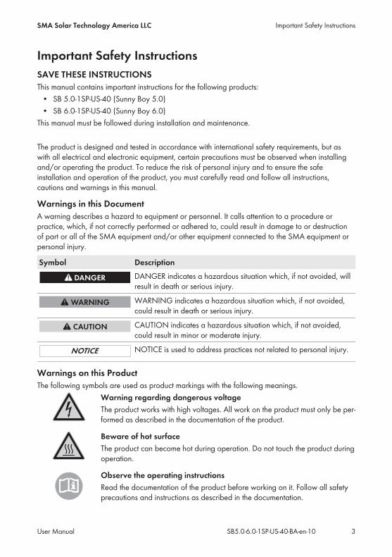
Important Safety InstructionsSAVE THESE INSTRUCTIONSThis manual contains important instructions for the following products:• SB 5.0-1SP-US-40 (Sunny Boy 5.0)• SB 6.0-1SP-US-40 (Sunny Boy 6.0)This manual must be followed during installation and maintenance.
The product is designed and tested in accordance with international safety requirements, but aswith all electrical and electronic equipment, certain precautions must be observed when installingand/or operating the product. To reduce the risk of personal injury and to ensure the safeinstallation and operation of the product, you must carefully read and follow all instructions,cautions and warnings in this manual.
Warnings in this DocumentA warning describes a hazard to equipment or personnel. It calls attention to a procedure orpractice, which, if not correctly performed or adhered to, could result in damage to or destructionof part or all of the SMA equipment and/or other equipment connected to the SMA equipment orpersonal injury.
Symbol DescriptionDANGER indicates a hazardous situation which, if not avoided, willresult in death or serious injury.
WARNING indicates a hazardous situation which, if not avoided,could result in death or serious injury.
CAUTION indicates a hazardous situation which, if not avoided,could result in minor or moderate injury.
NOTICE is used to address practices not related to personal injury.
Warnings on this ProductThe following symbols are used as product markings with the following meanings.
Warning regarding dangerous voltageThe product works with high voltages. All work on the product must only be per-formed as described in the documentation of the product.
Beware of hot surfaceThe product can become hot during operation. Do not touch the product duringoperation.
Observe the operating instructionsRead the documentation of the product before working on it. Follow all safetyprecautions and instructions as described in the documentation.
Important Safety InstructionsSMA Solar Technology America LLC
User Manual 3SB5.0-6.0-1SP-US-40-BA-en-10

General Warnings
All electrical installations must be carried out in accordance with the local electrical standardsand the National Electrical Code® ANSI/NFPA 70 or the Canadian Electrical Code® CSAC22.1. This document does not replace and is not intended to replace any local, state,provincial, federal or national laws, regulations or codes applicable to the installation and use ofthe product, including without limitation applicable electrical safety codes. All installations mustconform with the laws, regulations, codes and standards applicable in the jurisdiction ofinstallation. SMA assumes no responsibility for the compliance or non-compliance with such lawsor codes in connection with the installation of the product. The product contains no user-serviceable parts. Before installing or using the product, read all of the instructions, cautions, and warnings in thismanual. Before connecting the product to the electrical utility grid, contact the local utility company. Thisconnection must be made only by qualified personnel. Wiring of the product must be made by qualified personnel only.
General Warnings SMA Solar Technology America LLC
User ManualSB5.0-6.0-1SP-US-40-BA-en-104

Table of Contents1 Information on this Document ................................................. 71.1 Validity ................................................................................................ 71.2 Target group....................................................................................... 71.3 Symbols .............................................................................................. 71.4 Additional Information ....................................................................... 71.5 Nomenclature..................................................................................... 81.6 Typographies...................................................................................... 8
2 Safety......................................................................................... 92.1 Intended Use ...................................................................................... 92.2 Safety Information.............................................................................. 10
3 Product Description................................................................... 113.1 Sunny Boy........................................................................................... 113.2 Interfaces and Functions .................................................................... 133.3 LED Signals ......................................................................................... 15
4 Operation of the Inverter ......................................................... 174.1 Activating and Operating the Display .............................................. 174.2 Activate WPS Function....................................................................... 174.3 Secure Power Supply Operation ...................................................... 17
4.3.1 Activating Secure Power Supply Operation................................. 174.3.2 Deactivating Secure Power Supply Operation ............................ 18
5 Using the Inverter User Interface ............................................ 195.1 Establishing a connection to the user interface ................................ 19
5.1.1 Establishing a direct connection via WLAN................................. 195.1.2 Establishing a Direct Connection via Ethernet.............................. 205.1.3 Establishing a Connection via Ethernet in the local network....... 21
5.2 Logging Into the User Interface ......................................................... 225.3 Start Page Design of the User Interface............................................ 245.4 Starting the Installation Assistant ....................................................... 265.5 Changing the Password..................................................................... 27
6 Configuration of the Inverter ................................................... 29
Table of ContentsSMA Solar Technology America LLC
User Manual 5SB5.0-6.0-1SP-US-40-BA-en-10

6.1 Changing Operating Parameters...................................................... 296.2 Configuring the Country Data Set..................................................... 306.3 Deactivating the Arc-Fault Circuit Interrupter (AFCI)........................ 306.4 Changing the Operating Mode of the Multifunction Relay ............ 316.5 Configuring the Modbus Function .................................................... 326.6 Setting SMA OptiTrac Global Peak ................................................. 326.7 Saving the Configuration in a File..................................................... 336.8 Adopting a Configuration from a File............................................... 336.9 Switching the Dynamic Power Display Off....................................... 336.10 Switching WLAN On and Off........................................................... 34
7 Cleaning the Inverter................................................................ 35
8 Troubleshooting ........................................................................ 368.1 Forgotten Password............................................................................ 368.2 Event Messages ................................................................................. 378.3 Checking the PV System for Ground Faults ...................................... 558.4 Resetting the Operation Inhibition after Detection of an Arc Fault . 588.5 Updating the Firmware ...................................................................... 59
9 Accessories ................................................................................ 61
10 Compliance Information........................................................... 62
11 Contact....................................................................................... 63
Table of Contents SMA Solar Technology America LLC
User ManualSB5.0-6.0-1SP-US-40-BA-en-106

1 Information on this Document
1.1 ValidityThis document is valid for the following device types:• SB 5.0-1SP-US-40 (Sunny Boy 5.0)• SB 6.0-1SP-US-40 (Sunny Boy 6.0)
1.2 Target groupThis document is intended for qualified persons and end users. Only qualified persons are allowedto perform the activities marked in this document with a warning symbol and the caption"Qualified person". Tasks that do not require any particular qualification are not marked and canalso be performed by end users. Qualified persons must have the following skills:• Knowledge of how an inverter works and is operated• Training in how to deal with the dangers and risks associated with installing and usingelectrical devices and installations
• Training in the installation and commissioning of electrical devices and installations• Knowledge of the applicable standards and directives• Knowledge of and compliance with this document and all safety information
1.3 SymbolsSymbol Explanation
Sections describing activities to be performed by qualified personsonly
Information that is important for a specific topic or goal, but is notsafety-relevant
Indicates a requirement for meeting a specific goal
Desired result
A problem that might occur
1.4 Additional InformationLinks to additional information can be found at www.SMA-Solar.com:
Document title Document typeMounting, installation, commissioning and decommissioning Installation Manual
"Application for SMA Grid Guard Code" Certificate
"Webconnect Systems in Sunny Portal"Registration in Sunny Portal
User Manual
1 Information on this DocumentSMA Solar Technology America LLC
User Manual 7SB5.0-6.0-1SP-US-40-BA-en-10

Document title Document type"SMA Modbus® Interface"Information on the commissioning and configuration of the Modbusinterface
Technical Description
"SunSpec® Modbus® Interface"Information on the commissioning and configuration of the Modbusinterface
Technical Description
"SMA Modbus® Interface"Information about the device-specific Modbus registers
Technical Information
"SunSpec® Modbus® Interface"Information about the device-specific Modbus registers
Technical Information
1.5 NomenclatureComplete designation Designation in this documentSunny Boy Inverter, product
SMA Solar Technology America LLC SMA
SMA Solar Technology Canada Inc.
1.6 TypographiesTypography Use Examplebold • Display texts
• Elements on a user interface• Terminals• Elements to be selected• Elements to be entered
• The value can be found inthe field Energy.
• Select Settings.• Enter 10 in the field
Minutes.
> • Connects several elements to beselected
• Select Settings > Date.
[Button][Key]
• Button or key to be selected orpressed
• Select [Next].
1 Information on this Document SMA Solar Technology America LLC
User ManualSB5.0-6.0-1SP-US-40-BA-en-108

2 Safety
2.1 Intended UseThe Sunny Boy is a transformerless PV inverter with three MPP trackers, which converts the directcurrent of the PV array into grid-compliant alternating current and feeds it into the utility grid.The product is suitable for indoor and outdoor use.All components must remain within their permitted operating ranges at all times.The product must only be operated with PV arrays (PV modules and cabling) that are approved bythe electrical standards applicable on-site and the National Electrical Code® ANSI/NFPA 70 orthe Canadian Electrical Code® CSA C22.1.
No galvanic isolationThe product is not equipped with a transformer and therefore has no galvanic isolation.• Do not operate grounded PV modules together with the product. If grounded PV modulesare connected to the product, an event will occur which will appear on the productdisplay. The event will also be displayed, along with the associated message, in the eventlist on the user interface of the product.
• Only ground the mounting frames of the PV modules.• The neutral conductor of the AC output is not bonded to ground within the product.• The neutral conductor of the AC output for secure power supply operation is bonded toground within the product.
PV modules with a high capacity to ground may only be used if their coupling capacity does notexceed 2.5 μF.To protect the PV system against excessive reverse currents under fault conditions, the NationalElectrical Code®, Section 690.9, requires overcurrent protection for PV source circuits wherepossible short-circuit currents exceed the ampacity of source circuit conductors or the maximumseries fuse rating of the PV modules. Typically, this requires string fusing where more than twostrings are combined in parallel. Where overcurrent protection is required, National ElectricalCode®, Section 690.35, requires that both positive and negative conductors have overcurrentprotection for ungrounded PV arrays.The product must only be used in countries for which it is approved or released by SMA and thegrid operator.Use this product only in accordance with the information provided in the enclosed documentationand with the locally applicable standards and directives. Any other application may causepersonal injury or property damage.Alterations to the product, e.g. changes or modifications, are only permitted with the express writtenpermission of SMA. Unauthorized alterations will void guarantee and warranty claims and in mostcases terminate the operating license. SMA shall not be held liable for any damage caused bysuch changes.Any use of the product other than that described in the Intended Use section does not qualify asappropriate.The enclosed documentation is an integral part of this product. Keep the documentation in aconvenient place for future reference and observe all instructions contained therein.
2 SafetySMA Solar Technology America LLC
User Manual 9SB5.0-6.0-1SP-US-40-BA-en-10

The type label must remain permanently attached to the product.
2.2 Safety InformationThis section contains safety information that must be observed at all times when working on or withthe product.To prevent personal injury and property damage and to ensure long-term operation of the product,read this section carefully and observe all safety information at all times.
Danger to life due to electric shock in case of a ground faultIf a ground fault occurs, parts of the system may still be live. Touching live components can leadto lethal electric shocks.• Ensure that no voltage is present and wait five minutes before touching any parts of the PVsystem or the inverter.
Risk of burns from hot surfacesThe surface of the inverter can get very hot. Touching the surface can result in burns.• Mount the inverter in such a way that it cannot be touched inadvertently.• Do not touch hot surfaces.• Wait 30 minutes for the surface to cool sufficiently.• Observe the safety messages on the inverter.
Damage to the inverter due to moisture and dust intrusionDust or moisture intrusion can damage the inverter and impair its functionality.• Close all enclosure openings of the inverter tightly.• Never open the inverter when it is raining or snowing, or the humidity is over 95%.
Damage to the display or the type label due to the use of cleaning agents• If the inverter is dirty, clean the enclosure, the enclosure lid of the Connection Unit, theenclosure lid of the Power Unit, the type label, the display and the LEDs with a damp clothand clear water only.
2 Safety SMA Solar Technology America LLC
User ManualSB5.0-6.0-1SP-US-40-BA-en-1010

3 Product Description
3.1 Sunny BoyThe Sunny Boy is a transformerless PV inverter with three MPP trackers, which converts the directcurrent of the PV array into grid-compliant alternating current and feeds it into the utility grid.
Figure 1: Design of the Sunny Boy
Position DesignationA Power Unit
B Enclosure lid of the Power Unit
C Enclosure lid for the Connection Unit
D Connection Unit
E DC load-break switchThe inverter is equipped with a DC load-break switch. If the DC load-break switch isset to the position I, it establishes a conductive connection between the PV arrayand the Power Unit. Switching the DC load-break switch to the O position will inter-rupt the DC electric circuit.
3 Product DescriptionSMA Solar Technology America LLC
User Manual 11SB5.0-6.0-1SP-US-40-BA-en-10

Position DesignationF Inverter type label
The type label uniquely identifies the inverter. You will require the information onthe type label to use the product safely and when seeking customer support fromthe SMA Service Line. The type label must remain permanently attached to theproduct. You will find the following information on the type label:• Device type (Model)• Serial number (Serial No.)• Date of manufacture• Device-specific characteristics
G Type label of the Connection UnitThe type label clearly identifies the Connection Unit. The type label must remainpermanently attached to the product. You will find the following information on thetype label:• Identification key (PIC) for registration in Sunny Portal• Registration ID (RID) for registration in Sunny Portal• WLAN password (WPA2-PSK) for the direct connection to the user interfaceof the inverter via WLAN
H DisplayThe display shows the current operating data and events or errors.
I LEDsThe LEDs indicate the operating state of the inverter.
Symbols on the Inverter and on the Type Label
Symbol ExplanationInverterTogether with the green LED, this symbol indicates the operating state of the in-verter.
Observe the documentationTogether with the red LED, this symbol indicates an error.
Data transmissionTogether with the blue LED, this symbol indicates the status of the network con-nection.
Equipment Grounding TerminalThis symbol indicates the position for the connection of an equipment ground-ing conductor.
3 Product Description SMA Solar Technology America LLC
User ManualSB5.0-6.0-1SP-US-40-BA-en-1012

Symbol ExplanationWarning label with FCC Compliance and IC Compliance
Risk of burns due to hot surfaces.The product can get hot during operation. Avoid contact during operation.Prior to performing any work on the product, allow the product to cool downsufficiently.
Danger to life due to electric shockThe product operates at high voltages. Prior to performing any work on theproduct, disconnect the product from voltage sources. All work on the productmust be carried out by electrically qualified persons only.
Observe the documentationObserve all documentation supplied with the product.
UL1741 is the standard applied by Underwriters Laboratories to the productto certify that it meets the requirements of the National Electrical Code ®, theCanadian Electrical Code® CSA C22.1; the IEEE‑929‑2000 and IEEE 1547.
3.2 Interfaces and FunctionsUser interface for the monitoring and configuration of the inverterThe inverter is standard-equipped with an integrated web server, which provides a user interface forconfiguring and monitoring the inverter. The inverter user interface can be called up via the webbrowser if there is an existing WLAN or Ethernet connection to a computer, tablet PC orsmartphone.
Speedwire/WebconnectThe inverter is equipped with SMA Speedwire/Webconnect as standard. SMA Speedwire/Webconnect is a type of communication based on the Ethernet standard. This enables inverter-optimized 10/100 Mbit data transmission between Speedwire devices in PV systems. TheWebconnect function enables direct data transmission between the inverters of a small-scale plantand the Sunny Portal web-based monitoring platform without an additional SMA communicationdevice and for a maximum of 4 inverters per Sunny Portal system. In large-scale PV power plantswith more than 4 inverters, there is the option of establishing data transmission between theinverters and the Sunny Portal web-based monitoring platform via the SMA Cluster Controller or todistribute the inverters over several plants in the Sunny Portal. If there is an existing WLAN orEthernet connection, you can directly access your Sunny Portal system via the web browser on thecomputer, tablet PC or smartphone.
3 Product DescriptionSMA Solar Technology America LLC
User Manual 13SB5.0-6.0-1SP-US-40-BA-en-10

Class 1 wiring methods are to be used for field wiring connection to the terminals of thecommunication interface.
WLANThe inverter is equipped with a WLAN interface as standard. The inverter is delivered with theWLAN interface activated as standard. If you do not want to use WLAN, you can deactivate theWLAN interface.In addition, the inverter has a WPS (WiFi Protected Setup) function. The WPS function is forautomatically connecting the inverter to a device in the same network as the inverter (e.g. router,computer, tablet PC or smartphone).
Expanding the radio range in the WLAN networkIn order to expand the radio range of the inverter in the WLAN network, you can install theAntenna Extension Kit accessory set in the inverter.
ModbusThe inverter is equipped with a Modbus interface. The Modbus interface is deactivated by defaultand must be configured as needed.The Modbus interface of the supported SMA devices is designed for industrial use and has thefollowing tasks:• Remote query of measured values• Remote setting of operating parameters• Setpoint specifications for system control
4-String-OperationThe "4-String-Operation" function allows the DC inputs A and B of the inverter to operate in paralleland up to three strings to be connected to it in parallel. As a result, as opposed to normaloperation, up to four strings can be connected to the inverter. The inverter automatically detectswhether the DC inputs A and B are operated in parallel.
Module slotsThe inverter is standard-equipped with two module slots. The module slots are located on thecommunication assembly and allow additional modules to be connected (e.g. SMA SensorModule). The modules are available as accessories. The installation of two identical modules is notpermissible.
Secure power supply operationYou can connect an external outlet and a switch to the inverter in order to activate the outlet. Incase of a grid failure, the outlet supplies a load with current from the PV system. When the outlet isactivated via the switch, the load is supplied with current from the PV system. The inverterautomatically regulates the energy supply of the outlet depending on the solar irradiation on the PVsystem. When the outlet is activated and a load is supplied with current from the PV system, theinverter is disconnected from the utility grid and does not feed into the utility grid.
3 Product Description SMA Solar Technology America LLC
User ManualSB5.0-6.0-1SP-US-40-BA-en-1014

Do not connect loads that require a stable electricity supply to the outlet for securepower supply operationSecure power supply operation must not be used for loads that require a stable electricitysupply. The power available during secure power supply operation depends on the solarirradiation on the PV system. Therefore, power output can fluctuate considerably dependingon the weather or may not be available at all.• Do not connect loads to the outlet for secure power supply operation if they aredependent on a stable electricity supply for reliable operation.
Multifunction relayThe inverter is equipped with a multifunction relay as standard. The multifunction relay is amultifunctional interface that can be configured for the operating mode used by a particular system.
Arc-Fault Circuit Interrupter (AFCI)In accordance with the National Electrical Code®, Article 690.11, the inverter has a system for arcfault detection and interruption.An electric arc with a power of 300 W or greater must be interrupted by the AFCI in the timespecified by UL 1699B. A detected electric arc causes the inverter to interrupt feed-in operation: Inorder to restart feed-in operation, the feed-in operation must be activated manually. If theinstallation conditions allow it, you can deactivate the arc-fault circuit interrupter.
3.3 LED SignalsThe LEDs indicate the operating state of the inverter.
3 Product DescriptionSMA Solar Technology America LLC
User Manual 15SB5.0-6.0-1SP-US-40-BA-en-10

LED Status ExplanationGreen LED flashing: 2 s on
2 s offWaiting for connection conditionsThe conditions for feed-in operation are not yet met. Assoon as the conditions are met, the inverter will start feed-in operation.
flashing: 1.5 s on0.5 s off
Secure power supply operationThe secure power supply operation is activated and the in-verter supplies the outlet with current from the PV system.
flashing quickly Update of central processing unitThe central processing unit of the inverter is being up-dated.
glowing Feed-in operation (Power: ≥ 90%, relative to the active power limit set)The inverter feeds in with a power of at least 90%.
pulsing Feed-in operation (Power: ≥ 20% to max. 90%, relative to the set activepower limit)The inverter is equipped with a dynamic power display viathe green LED. The green LED pulses faster or slower, de-pending on the power. If necessary, you can switch off thedynamic power display via the green LED.
Red LED glowing Event occurredIn addition to the glowing red LED, the display indicatesthe following information about the event:• Event type• Event number• Date and time at wich the event occurred
Blue LED flashes slowly forapprox. oneminute
Communication connection is being establishedThe inverter is establishing a connection to a local networkor is establishing a direct connection to an end device viaEthernet (e.g. computer, tablet PC or smartphone).
flashes quickly forapprox. two min-utes
WPS activeThe WPS function is active.
glowing Communication activeThere is an active connection with a local network or thereis a direct connection with an end device via Ethernet (e.g.computer, tablet PC or smartphone).
3 Product Description SMA Solar Technology America LLC
User ManualSB5.0-6.0-1SP-US-40-BA-en-1016

4 Operation of the Inverter
4.1 Activating and Operating the DisplayYou can activate and operate the display by tapping on the enclosure lid of the Connection Unit.
Procedure:1. Activate the display. Tap on the enclosure lid of the Connection Unit once.☑ The backlight is switched on.
2. To move to the next message, tap on the enclosure lid of the Connection Unit once.
4.2 Activate WPS Function• Tap twice on the enclosure lid of the Connection Unit.☑ The blue LED flashes quickly for approx. two minutes.
4.3 Secure Power Supply Operation
4.3.1 Activating Secure Power Supply OperationIf an outlet and a switch for secure power supply operation are connected to the inverter, you cansupply a load with current from the PV system in case of a grid failure during the day. If youactivate the secure power supply operation, the inverter supplies loads that are connected to theoutlet for secure power supply operation.In case of overload, underload or insufficient solar irradiation, the voltage supply of the outlet isbriefly interrupted. The inverter automatically attempts to reestablish the voltage supply 20 secondsafter the interruption. This can lead to inadvertent starting of the load that is connected to the outlet.Ensure that the load connected to the outlet does not consume too much power. If necessary,reduce the power consumption of the load.
In case of a grid failure during the night, secure power supply operation is notpossibleDuring the night, secure power supply operation cannot be activated since the PV system doesnot produce power that is required to supply the load.• In case of a grid failure during the night, do not activate secure power supply operation.• Continue to operate the inverter on the utility grid and wait for restoration of gridoperation.
• In the event of a persistent grid failure, switch to secure power supply operation aftersunrise.
4 Operation of the InverterSMA Solar Technology America LLC
User Manual 17SB5.0-6.0-1SP-US-40-BA-en-10

Do not connect loads that require a stable electricity supply to the outlet for securepower supply operationSecure power supply operation must not be used for loads that require a stable electricitysupply. The power available during secure power supply operation depends on the solarirradiation on the PV system. Therefore, power output can fluctuate considerably dependingon the weather or may not be available at all.• Do not connect loads to the outlet for secure power supply operation if they aredependent on a stable electricity supply for reliable operation.
Procedure:1. If no load is connected to the outlet, connect a load.2. Turn the switch of the outlet to secure power supply operation.3. Wait one minute.☑ The inverter commences secure power supply operation. As soon as the inverter supplies theoutlet with power, the green LED flashes (1.5 s on and 0.5 s off) and the message SPS-modeactive is shown in the display along with the amount of power being supplied from theinverter to the outlet. In addition, the control light of the outlet for secure power supplyoperation glows.
✖ The green LED does not flash and no message that the secure power supply operation mode isactivated appears on the display or the control lamp of the outlet does not glow?The output power of the PV system is too low. Irradiation on the PV system is probably too lowor the connected load requires more power than currently available.• Ensure that the outlet's switch is set to secure power supply operation.• If irradiation is too low, wait for it to increase.• Connect a load with lower power consumption to the outlet.
✖ No voltage can be measured at the outlet?• Ensure that the outlet's switch is set to secure power supply operation.• Ensure that the switch, outlet and control light for secure power supply operation arecorrectly connected.
4.3.2 Deactivating Secure Power Supply Operation1. If necessary, disconnect the load from the outlet.2. Turn the switch of the outlet to grid operation.☑ Grid operation is activated.
3. Switch on the circuit breaker of the PV system.☑ The inverter connects to the utility grid and starts feed-in operation.
4 Operation of the Inverter SMA Solar Technology America LLC
User ManualSB5.0-6.0-1SP-US-40-BA-en-1018

5 Using the Inverter User Interface
5.1 Establishing a connection to the user interface
5.1.1 Establishing a direct connection via WLANRequirements:☐ The inverter must be commissioned.☐ A computer, tablet PC or smartphone with WLAN interface must be available.☐ In the case of a computer connection, one of the following web browsers must be installed:Firefox (as of version 25), Internet Explorer (as of version 10), Safari (as of version 7), Opera(as of version 17) or Google Chrome (as of version 30).
☐ In the case of a tablet PC or smartphone connection, one of the following web browsers mustbe installed: Firefox (as of version 25), Safari (as of version iOS 7) or Google Chrome (as ofversion 29).
☐ The personal SMA Grid Guard code of the Installer must be available for the changing ofgrid-relevant settings after completion of the first ten operating hours (see "Application forSMA Grid Guard Code" at www.SMA-Solar.com).
Inverter SSID and IP address and necessary passwords• Inverter SSID in WLAN: SMA[serial number] (e.g. SMA2130019815)• Standard WLAN password (usable for initial configuration to completion of the first tenoperating hours): SMA 12345
• Device-specific WLAN password (usable for initial configuration to completion of the firstten operating hours): see WPA2-PSK on the type label of the inverter
• Standard IP inverter address for a direct connection via WLAN outside of a localnetwork: 192.168.12.3
Importing and exporting files with end devices having an iOS operating system isnot possible.For technical reasons, importing and exporting files (e.g. importing an inverter configuration,saving the current inverter configuration or exporting events) is not possible with mobile enddevices having an iOS operating system.• Use an end device that does not have an iOS operating system for importing andexporting files.
The procedure can be different depending on the terminal devices used (e.g. computer, tablet PCor smartphone). If the procedure described does not apply to your device, establish the directconnection via WLAN as described in the manual of your device.
Procedure:1. If your computer, tablet PC or smartphone has a WPS function:• Activate the WPS function on the inverter. To do this, tap twice on the enclosure lid of theConnection Unit.☑ The blue LED flashes quickly. The WPS function is active.
5 Using the Inverter User InterfaceSMA Solar Technology America LLC
User Manual 19SB5.0-6.0-1SP-US-40-BA-en-10
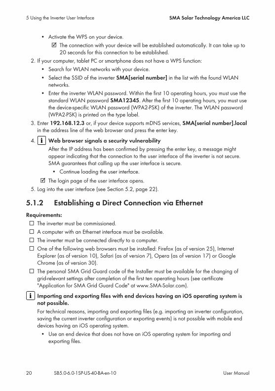
• Activate the WPS on your device.☑ The connection with your device will be established automatically. It can take up to20 seconds for this connection to be established.
2. If your computer, tablet PC or smartphone does not have a WPS function:• Search for WLAN networks with your device.• Select the SSID of the inverter SMA[serial number] in the list with the found WLANnetworks.
• Enter the inverter WLAN password. Within the first 10 operating hours, you must use thestandard WLAN password SMA12345. After the first 10 operating hours, you must usethe device-specific WLAN password (WPA2-PSK) of the inverter. The WLAN password(WPA2-PSK) is printed on the type label.
3. Enter 192.168.12.3 or, if your device supports mDNS services, SMA[serial number].localin the address line of the web browser and press the enter key.
4. Web browser signals a security vulnerabilityAfter the IP address has been confirmed by pressing the enter key, a message mightappear indicating that the connection to the user interface of the inverter is not secure.SMA guarantees that calling up the user interface is secure.• Continue loading the user interface.
☑ The login page of the user interface opens.5. Log into the user interface (see Section 5.2, page 22).
5.1.2 Establishing a Direct Connection via EthernetRequirements:☐ The inverter must be commissioned.☐ A computer with an Ethernet interface must be available.☐ The inverter must be connected directly to a computer.☐ One of the following web browsers must be installed: Firefox (as of version 25), InternetExplorer (as of version 10), Safari (as of version 7), Opera (as of version 17) or GoogleChrome (as of version 30).
☐ The personal SMA Grid Guard code of the Installer must be available for the changing ofgrid-relevant settings after completion of the first ten operating hours (see certificate"Application for SMA Grid Guard Code" at www.SMA-Solar.com).
Importing and exporting files with end devices having an iOS operating system isnot possible.For technical reasons, importing and exporting files (e.g. importing an inverter configuration,saving the current inverter configuration or exporting events) is not possible with mobile enddevices having an iOS operating system.• Use an end device that does not have an iOS operating system for importing andexporting files.
5 Using the Inverter User Interface SMA Solar Technology America LLC
User ManualSB5.0-6.0-1SP-US-40-BA-en-1020
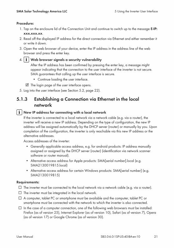
Procedure:1. Tap on the enclosure lid of the Connection Unit and continue to switch up to the message E-IP:
xxx.xxx.xx.2. Read off the displayed IP address for the direct connection via Ethernet and either remember itor write it down.
3. Open the web browser of your device, enter the IP address in the address line of the webbrowser and press the enter key.
4. Web browser signals a security vulnerabilityAfter the IP address has been confirmed by pressing the enter key, a message mightappear indicating that the connection to the user interface of the inverter is not secure.SMA guarantees that calling up the user interface is secure.• Continue loading the user interface.
☑ The login page of the user interface opens.5. Log into the user interface (see Section 5.2, page 22).
5.1.3 Establishing a Connection via Ethernet in the localnetwork
New IP address for connecting with a local networkIf the inverter is connected to a local network via a network cable (e.g. via a router), theinverter will receive a new IP address. Depending on the type of configuration, the new IPaddress will be assigned automatically by the DHCP server (router) or manually by you. Uponcompletion of the configuration, the inverter is only reachable via this new IP address or thealternative addresses.Access addresses of the inverter:• Generally applicable access address, e.g. for android products: IP address manuallyassigned or assigned by the DHCP server (router) (identification via network scannersoftware or router manual).
• Alternative access address for Apple products: SMA[serial number].local (e.g.SMA2130019815.local)
• Alternative access address for certain Windows products: SMA[serial number] (e.g.SMA2130019815)
Requirements:☐ The inverter must be connected to the local network via a network cable (e.g. via a router).☐ The inverter must be integrated in the local network.☐ A computer, tablet PC or smartphone must be available and the computer, tablet PC orsmartphone must be connected with the network to which the inverter is also connected.
☐ In the case of a computer connection, one of the following web browsers must be installed:Firefox (as of version 25), Internet Explorer (as of version 10), Safari (as of version 7), Opera(as of version 17) or Google Chrome (as of version 30).
5 Using the Inverter User InterfaceSMA Solar Technology America LLC
User Manual 21SB5.0-6.0-1SP-US-40-BA-en-10

☐ In the case of a tablet PC or smartphone connection, one of the following web browsers mustbe installed: Firefox (as of version 25), Safari (as of version iOS 7) or Google Chrome (as ofversion 29).
☐ The personal SMA Grid Guard code of the Installer must be available for the changing ofgrid-relevant settings after completion of the first ten operating hours (see certificate"Application for SMA Grid Guard Code" at www.SMA-Solar.com).
Importing and exporting files with end devices having an iOS operating system isnot possible.For technical reasons, importing and exporting files (e.g. importing an inverter configuration,saving the current inverter configuration or exporting events) is not possible with mobile enddevices having an iOS operating system.• Use an end device that does not have an iOS operating system for importing andexporting files.
Procedure:1. Open the web browser of your device, enter the IP address of the inverter in the address lineof the web browser and press the enter key.
2. Web browser signals a security vulnerabilityAfter the IP address has been confirmed by pressing the enter key, a message mightappear indicating that the connection to the user interface of the inverter is not secure.SMA guarantees that calling up the user interface is secure.• Continue loading the user interface.
☑ The login page of the user interface opens.3. Log into the user interface (see Section 5.2, page 22).
5.2 Logging Into the User InterfaceAfter a connection to the user interface of the inverter has been established, the login page opens.Log onto the user interface as described below.
Usage of cookiesFor the correct display of the user interface, cookies are required. The cookies are used forconvenience only. By using this user interface you agree to the placement of cookies.
Procedure:• If you access the user interface for the first time, you have to log in as an "User."• If you have accessed the user interface once, you can log in as a user or installer.
Log in as a user for the first time1. In the drop-down list Language, select the desired language.2. In the User group drop-down list, select the entry User.3. In the New password field, enter a new password for the User user group.
5 Using the Inverter User Interface SMA Solar Technology America LLC
User ManualSB5.0-6.0-1SP-US-40-BA-en-1022

4. In the Repeat password field, enter the new password again.5. Select Login.☑ The start page of the user interface opens.
Log in as the user or installer.1. In the drop-down list Language, select the desired language.2. In the User group drop-down list, select the entry Installer or User.3. Enter the password in the field Password.4. Select Login.☑ The start page of the user interface opens.
5 Using the Inverter User InterfaceSMA Solar Technology America LLC
User Manual 23SB5.0-6.0-1SP-US-40-BA-en-10

5.3 Start Page Design of the User Interface
A B C
E
F
D
Figure 2: Start Page Design of the User Interface
5 Using the Inverter User Interface SMA Solar Technology America LLC
User ManualSB5.0-6.0-1SP-US-40-BA-en-1024

Position Designation DescriptionA Menu Provides the following functions:
• HomeOpens the user interface homepage
• Instantaneous valuesCurrent measured values of the inverter
• Device ParametersThe various operating parameters of the inverter canbe viewed and configured here depending on theuser group.
• EventsAll events that have occurred in the selected timeperiod are displayed here. The event types areInformation, Warning and Error. Currentlyexisting events of the types Error and Warning willbe additionally displayed in the Device statusviewlet. However, only the higher-priority event isdisplayed. If, for example, there is a Warning and anError present at the same time, only the Error will bedisplayed.
• System ConfigurationThe following settings for the inverter can beperformed here. The selection available is dependenton which user group you are logged in as and theoperating system of the device with which the userinterface has been called up.– Changing device names– Updating firmware (not available with deviceshaving an iOS operating system)
– Saving a configuration to file (not available withdevices having an iOS operating system)
– Loading a configuration from a file (notavailable with devices having an iOS operatingsystem)
– Importing a proxy certificate (not available withdevices having an iOS operating system)
B User settings Provides the following functions, depending on the usergroup logged in:• Start the installation assistant• SMA Grid Guard login• Logout
5 Using the Inverter User InterfaceSMA Solar Technology America LLC
User Manual 25SB5.0-6.0-1SP-US-40-BA-en-10

Position Designation DescriptionC Help Provides the following functions:
• Displaying information on Open Source licenses used• Link to the website of SMA
D Status bar Displays the following information:• Inverter serial number• Inverter firmware version• IP address of the inverter within the local networkand/or IP address of the inverter during WLANconnection
• User group logged in• Date and device time of the inverter
E PV power curve Temporal progression of the PV power of the householdover the selected time period.
F Status display The various areas display information on the current statusof the PV system.• Device statusDisplays whether the inverter is currently in a fault-free operating state or whether there is an event typeError or Warning present.
• Current powerDisplays the power currently being generated by theinverter.
• YieldDisplays the energy yield of the inverter.
• Feed-in managementDisplays whether the inverter is currently limiting itsactive power.
5.4 Starting the Installation Assistant
The installation assistant leads you step-by-step through the steps necessary for the initialconfiguration of the inverter.
Requirements:☐ When configuring after completion of the first ten operating hours, the SMA Grid Guard codemust be available (see "Application for SMA Grid Guard Code" at www.SMA-Solar.com).
5 Using the Inverter User Interface SMA Solar Technology America LLC
User ManualSB5.0-6.0-1SP-US-40-BA-en-1026

Procedure:1. Activate the user interface (see Section 5.1, page 19).2. Log in as Installer.3. Select the menu User Settings (see Section 5.3 "Start Page Design of the User Interface",page 24) on the start page of the user interface.
4. In the subsequent context menu, select [Start the installation assistant].☑ The Installation Assistant will open.
A
C
B
Figure 3: Layout of the installation assistant
Position Designation DescriptionA Configuration steps Overview of the installation assistant steps. The number of
steps depends on the type of device and the additionallyinstalled modules. The current step is highlighted in blue.
B User information Information about the current configuration step and thesetting options of the configuration step.
C Configuration field You can make settings in this field.
5.5 Changing the PasswordThe password for the inverter can be changed for both user groups. Furthermore, the user groupInstaller can change the password for the user group User as well as its own password.
5 Using the Inverter User InterfaceSMA Solar Technology America LLC
User Manual 27SB5.0-6.0-1SP-US-40-BA-en-10

PV systems registered in a communication productWith PV systems that are registered in a communication product (e.g. Sunny Portal,Cluster Controller), you can also assign a new password for the user group Installer via thecommunication product. The password for the user group Installer is also the systempassword. If you assign a password for the user group Installer via the user interface of theinverter that does not correspond to the system password in the communication product, theinverter can no longer be reached by the communication product.• Ensure that the password for the user group Installer is the same as the system passwordin the communication product.
Procedure:1. Activate the user interface (see Section 5.1, page 19).2. Log into the user interface (see Section 5.2, page 22).3. Call up the menu Device Parameters.4. Select [Edit parameters].5. In the parameter group User Rights > Access Control change the password of the desireduser group.
6. Select [Save all] to save the changes.
5 Using the Inverter User Interface SMA Solar Technology America LLC
User ManualSB5.0-6.0-1SP-US-40-BA-en-1028

6 Configuration of the Inverter
6.1 Changing Operating ParametersThe operating parameters of the inverter are set to certain values by default. You can change theoperating parameters to optimize the performance of the inverter.This section describes the basic procedure for changing operating parameters. Always changeoperating parameters as described in this section. Some function-sensitive parameters can only beviewed by qualified persons and can only be changed by qualified persons by entering thepersonal SMA Grid Guard code.
No configuration via Sunny ExplorerSunny Explorer does not support the configuration of inverters with their own user interface.The inverter can be detected via Sunny Explorer, however it is expressly not recommended touse Sunny Explorer to configure this inverter. SMA does not accept liability for missing orincorrect data and possibly resulting yield losses.• Use the user interface for the configuration of the inverter.
Requirements:☐ The changes to the grid-relevant parameters must be approved by the grid operator.☐ When changing grid-relevant parameters, the SMA Grid Guard code must be available (see"Application for SMA Grid Guard Code" at www.SMA-Solar.com).
Procedure:1. Activate the user interface (see Section 5.1, page 19).2. Log into the user interface (see Section 5.2, page 22).3. Call up the menu Device Parameters.4. Select [Edit parameters].5. Log in using the SMA Grid Guard code to change those parameters designated by a lock(only for installers):• Select the menu User Settings (see Section 5.3, page 24).• In the subsequent context menu, select [SMA Grid Guard login].• Enter the SMA Grid Guard code and select [Login].
6. Change the desired parameters.7. Select [Save all] to save the changes.☑ The inverter parameters are set.
6 Configuration of the InverterSMA Solar Technology America LLC
User Manual 29SB5.0-6.0-1SP-US-40-BA-en-10

Accepting the settingsSaving the made settings is indicated by an hourglass symbol on the user interface. If the DCvoltage is sufficient, the data is transferred directly to the inverter and accepted. If the DCvoltage is too low (e. g. in the evening), the settings are saved, but they cannot be directlytransferred to or accepted by the inverter. As long as the inverter has not yet received andaccepted the settings, the hourglass symbol will continue to be displayed on the user interface.The settings will be accepted when there is sufficient DC voltage applied and the inverterrestarts. As soon as the hourglass symbol appears on the user interface, the settings have beensaved. The settings will not be lost. You can log off of the user interface and leave the system.
6.2 Configuring the Country Data Set
As standard, the inverter is meant for connection to a utility grid with a 208 V wye connection or a240 V split-phase system, and the associated country data set UL1741/2010/120 is factory-set.If the default country data set does not correspond with the grid configuration, the country data setcan be adapted to the connected grid configuration.The basic procedure for changing operating parameters is explained in another section (seeSection 6.1 "Changing Operating Parameters", page 29).
Grid configuration Country data set208 V delta connection UL1741/2010/208
208 V wye connection UL1741/2010/120
240 V delta connection UL1741/2010/240
240 V split-phase system UL1741/2010/120
Procedure:• Select the parameter Set country standard and set the required country data set.
6.3 Deactivating the Arc-Fault Circuit Interrupter (AFCI)
The basic procedure for changing operating parameters is explained in another section (seeSection 6.1 "Changing Operating Parameters", page 29).
Procedure:• Select the parameter AFCI switched on or AfciIsOn and set to No.
6 Configuration of the Inverter SMA Solar Technology America LLC
User ManualSB5.0-6.0-1SP-US-40-BA-en-1030

6.4 Changing the Operating Mode of the MultifunctionRelay
The default operating mode of the multifunction relay is Fault indication (FltInd) . If you decide touse another operating mode and have established the correct electrical connection for thisoperating mode and the associated connection variant, you will have to change the operatingmode of the multifunction relay and make other settings, if necessary.The basic procedure for changing operating parameters is explained in another section (seeSection 6.1 "Changing Operating Parameters", page 29).
Procedure:1. Select the parameter Operating mode of multifunction relay or Mlt.OpMode and set thedesired operating mode.
2. Once you have set the operating mode Self-consumption or SelfCsmp, you can configureother settings:• Select the parameter Minimum On power for MFR self-consumption or
Mlt.MinOnPwr and set the desired value. This will configure the power threshold fromwhich a load is to be activated.
• Select the parameter Minimum power On time, MFR self-consumption orMlt.MinOnPwrTmm and set the desired value. This will configure the minimum time forwhich the power must have exceeded the minimum switch-on power threshold in order totrip activation of the load.
• Select the parameter Minimum On time for MFR self-consumption orMlt.MinOnTmm and set the desired value. This will configure the minimum time forwhich the load remains activated.
3. If you have set the operating mode Control via communication or ComCtl, select theparameter Status of MFR with control via communication or Mlt.ComCtl.Sw and set thedesired value. This will configure the status at which the multifunction relay is controlled via acommunication product.
4. If you have set the operating mode Battery bank or BatCha, make further settings:• Select the parameter Minimum On power for MFR battery bank or
Mlt.BatCha.Pwr and set the desired value. This will configure the power threshold fromwhich the battery is to be charged.
• Select the parameter Minimum time before reconnection of MFR battery bank orMlt.BatCha.Tmm and set the desired value. This will configure the minimum time whichmust elapse after charging the battery before the battery can be charged again.
6 Configuration of the InverterSMA Solar Technology America LLC
User Manual 31SB5.0-6.0-1SP-US-40-BA-en-10

6.5 Configuring the Modbus Function
The Modbus interface is deactivated by default and the communication ports 502 set. In order toaccess SMA invertes with SMA Modbus® or SunSpec® Modbus®, the Modbus interface must beactivated. After activating the interface, the communication ports of both IP protocols can bechanged.For information on commissioning and configuration of the Modbus interface, see the TechnicalDescriptions "SMA Modbus® Interface" or in the Technical Descriptions "SunSpec® Modbus®Interface" at www.SMA-Solar.com.For information on which Modbus registers are supported, see the Technical Descriptions "SMAModbus® Interface" or "SunSpec® Modbus® Interface" at www.SMA-Solar.com.
Data security during activated Modbus interfaceIf you activate the Modbus interface, there is a risk that unauthorized users may access andmanipulate the data or devices in your PV system.• Take appropriate protective measures such as:– Set up a firewall.– Close unnecessary network ports.– Only enable remote access via VPN tunnel.– Do not set up port forwarding at the communication port in use.– In order to deactivate the Modbus interface, reset the inverter to default settings.
Procedure:• Activate the Modbus interface and adjust the communication ports if necessary (see theTechnical Descriptions "SMA Modbus® Interface" or "SunSpec® Modbus® Interface" atwww.SMA-Solar.com).
6.6 Setting SMA OptiTrac Global Peak
For partially shaded PV modules, you should set the interval at which the inverter is to optimize theMPP of the PV system. If you do not want to use SMA OptiTrac Global Peak feature, you candeactivate the feature.The basic procedure for changing operating parameters is explained in another section (seeSection 6.1 "Changing Operating Parameters", page 29).
Procedure:• Select the parameter Cycle time of the OptiTrac Global Peak algorithm or
MPPShdw.CycTms and set the required time interval. The ideal time interval is usually sixminutes. This value should only be increased if the shading situation changes extremely slowly.☑ The inverter optimizes the MPP of the PV system at the predetermined time interval.
• In order to deactivate the SMA OptiTrac Global Peak feature, select the parameter OptiTracGlobal Peak switched on or set MPPShdw.IsOn to Off.
6 Configuration of the Inverter SMA Solar Technology America LLC
User ManualSB5.0-6.0-1SP-US-40-BA-en-1032

6.7 Saving the Configuration in a FileYou can save the current configuration of the inverter in a file. You can use this file as a databackup for this inverter and then import this file into this inverter again or another inverter toconfigure the inverter. When saving, only the device parameters will be saved, not any passwords.
Procedure:1. Activate the user interface (see Section 5.1, page 19).2. Log into the user interface (see Section 5.2, page 22).3. Select the menu System Configuration.4. Select [Settings].5. In the context menu, select [Saving the configuration in a file].6. Follow the instructions in the dialog.
6.8 Adopting a Configuration from a File
To configure the inverter, you can adopt the configuration from a file. To be able to do this, youmust first save the configuration of another inverter in a file (see Section 6.7 "Saving theConfiguration in a File", page 33). When saving, only the device parameters will be adopted, notany passwords.
Requirements:☐ The SMA Grid Guard code must be available (see "Application for SMA Grid Guard Code"at www.SMA-Solar.com).
☐ Changes to grid-relevant parameters must be approved by the responsible grid operator.
Procedure:1. Activate the user interface (see Section 5.1, page 19).2. Log into the user interface as an Installer.3. Select the menu System Configuration.4. Select [Settings].5. In the context menu, select [Adopting the configuration from a file].6. Follow the instructions in the dialog.
6.9 Switching the Dynamic Power Display OffAs standard, the inverter signals its power dynamically via the pulsing of the green LED. Whendoing so, the LED flashes on and off uniformly or is permanently lit at full power. The variousgradations are related here to the set active power limit of the inverter. If this display is not desired,switch this function off in accordance with the following procedure. Once this has been done, thegreen LED is lit permanently to signalize feed-in operation.The basic procedure for changing operating parameters is explained in another section (seeSection 6.1 "Changing Operating Parameters", page 29).
6 Configuration of the InverterSMA Solar Technology America LLC
User Manual 33SB5.0-6.0-1SP-US-40-BA-en-10

Procedure:• In the parameter group Device > Operation, select the parameter Dynamic power
display via green LED and set this to Off.
6.10 Switching WLAN On and OffThe inverter is equipped with an activated WLAN interface as standard. If you do not want to useWLAN, you can switch the WLAN function off and switch it on again whenever needed. In doingso, you can switch the WLAN direct connection and the WLAN connection in the local network onindependently of each other.
Switching on the WLAN function only possible via Ethernet connectionIf you switch off both the WLAN function for the direct connection and for the connection inthe local network, access to the inverter user interface and therefore reactivation of the WLANinterface is only possible via an Ethernet connection.
Switching WLAN offIf you would like to switch the WLAN function off completely, you must switch off both the directconnection and the connection in the local network.The basic procedure for changing operating parameters is explained in another section (seeSection 6.1 "Changing Operating Parameters", page 29).
Procedure:• To switch off the direct connection, select the parameter Soft-access-point is turned on andset this to No.
• To switch off the connection in the local network, select the parameter WLAN is turned onand set this to No.
Switching WLAN onIf you have switched the WLAN function for direct connection or for connection in the local networkoff, you can switch the WLAN function back on in accordance with the following procedure. Indoing so, you can switch the WLAN direct connection and the WLAN connection in the localnetwork on independently of each other.The basic procedure for changing operating parameters is explained in another section (seeSection 6.1 "Changing Operating Parameters", page 29).
Requirement:☐ If the WLAN function was previously switched off completely, the inverter must be connectedto a computer or router via Ethernet.
Procedure:• To switch on the WLAN direct connection, in the parameter group PV system
communication > WLAN, select the parameter Soft-access-point is turned on and set thisto Yes.
• To switch on the WLAN connection in the local network, in the parameter group Systemcommunication > WLAN, select the parameter WLAN is turned on and set this to Yes.
6 Configuration of the Inverter SMA Solar Technology America LLC
User ManualSB5.0-6.0-1SP-US-40-BA-en-1034

7 Cleaning the Inverter
Damage to the display or the type label due to the use of cleaning agents• If the inverter is dirty, clean the enclosure, the enclosure lid of the Connection Unit, theenclosure lid of the Power Unit, the type label, the display and the LEDs with a damp clothand clear water only.
7 Cleaning the InverterSMA Solar Technology America LLC
User Manual 35SB5.0-6.0-1SP-US-40-BA-en-10

8 Troubleshooting
8.1 Forgotten PasswordIf you have forgotten the password for the inverter, you can unlock the inverter with a PersonalUnlocking Key (PUK). For each inverter, there is one PUK for each user group (User and Installer). Useful hint: With PV systems in Sunny Portal, you can also assign a new password via Sunny Portalfor the user group Installer. The password for the user group Installer is the same as the systempassword in Sunny Portal.
Procedure:1. Request PUK (application form available at www.SMA-Solar.com).2. Activate the user interface (see Section 5.1, page 19).3. Enter the PUK instead of the password into the field Password.4. Call up the menu Device Parameters.5. Select [Edit parameters].6. In the parameter group User Rights > Access Control change the password of the desireduser group.
7. Select [Save all] to save the changes.
PV Systems in Sunny PortalThe password for the user group Installer is also the system password for the PV system inSunny Portal. Changing the password of the user group Installer can lead to the inverter nolonger being able to be reached by Sunny Portal.• Assign the changed password of the user group Installer as the new system password inSunny Portal (see the Sunny Portal user manual at www.SMA-Solar.com).
8 Troubleshooting SMA Solar Technology America LLC
User ManualSB5.0-6.0-1SP-US-40-BA-en-1036

8.2 Event MessagesEvent number Message, cause and corrective measures101 to 105
Grid faultThe grid voltage or grid impedance at the connection point of the inverter istoo high. The inverter has disconnected from the utility grid.Corrective measures:• Ensure that the correct country data set has been configured (seeSection 6.2, page 30).
• Check whether the grid voltage at the connection point of the inverter ispermanently in the permissible range.If the grid voltage is outside the permissible range due to local gridconditions, contact the grid operator. The grid operator must agree withan adjustment of the voltage at the feed-in point or with a change of themonitored operating limits.If the grid voltage is permanently within the permissible range and thismessage is still displayed, contact the Service (see Section 11 "Contact",page 63).
202 to 206
Grid faultThe utility grid has been disconnected, the AC cable is damaged or the gridvoltage at the connection point of the inverter is too low. The inverter has dis-connected from the utility grid.Corrective measures:• Make sure that the circuit breaker is switched on.• Ensure that the AC cable is not damaged and that it is connectedcorrectly.
• Ensure that the country data set has been configured correctly.• Check whether the grid voltage at the connection point of the inverter ispermanently in the permissible range.If the grid voltage is outside the permissible range due to local gridconditions, contact the grid operator. The grid operator must agree withan adjustment of the voltage at the feed-in point or with a change of themonitored operating limits.If the grid voltage is permanently within the permissible range and thismessage is still displayed, contact the Service (see Section 11 "Contact",page 63).
8 TroubleshootingSMA Solar Technology America LLC
User Manual 37SB5.0-6.0-1SP-US-40-BA-en-10

Event number Message, cause and corrective measures401 to 404
Grid faultThe inverter has disconnected from the utility grid. A stand-alone grid or a verylarge change in the power frequency was detected.Corrective measures:• Check the grid connection for significant short-term frequency fluctuations.
501
Grid faultThe power frequency is not within the permissible range. The inverter has dis-connected from the utility grid.Corrective measures:• If possible, check the power frequency and observe how oftenfluctuations occur.If fluctuations occur frequently and this message is displayed often,contact the grid operator and request approval to change the operatingparameters of the inverter.If the grid operator gives his approval, discuss any changes to theoperating parameters with Service (see Section 11 "Contact", page 63).
601
Grid faultThe inverter has detected an excessively high proportion of direct current inthe grid current.Corrective measures:• Check the grid connection for direct current.• If this message is displayed frequently, contact the grid operator andcheck whether the monitoring threshold on the inverter can be raised.
8 Troubleshooting SMA Solar Technology America LLC
User ManualSB5.0-6.0-1SP-US-40-BA-en-1038

Event number Message, cause and corrective measures701
Frq. not permitted > Check parameterThe power frequency is not within the permissible range. The inverter has dis-connected from the utility grid.Corrective measures:• If possible, check the power frequency and observe how oftenfluctuations occur.If fluctuations occur frequently and this message is displayed often,contact the grid operator and request approval to change the operatingparameters of the inverter.If the grid operator gives his approval, discuss any changes to theoperating parameters with Service (see Section 11 "Contact", page 63).
1001
L/N swapped > Check connectionThe connection of L and N is swapped.Corrective measures:• Ensure that L and N are correctly connected (see installation manual).
1302
Waiting for grid voltage > Installation failure grid connection > Checkgrid and fusesL or N not connected.Corrective measures:• Ensure that L and N are connected (see installation manual).• Ensure that the AC conductors are not damaged and correctly connected(see installation manual).
• Make sure that the circuit breaker is switched on.
1501
Reconnection fault gridThe changed country data set or the value of a parameter you have set doesnot correspond to the local requirements. The inverter cannot connect to theutility grid.Corrective measures:• Ensure that the country data set has been configured correctly. To do this,select the parameter Set country standard and check the value.
8 TroubleshootingSMA Solar Technology America LLC
User Manual 39SB5.0-6.0-1SP-US-40-BA-en-10

Event number Message, cause and corrective measures3301 to 3303
Unstable operationThere is not enough power at the DC input of the inverter for stable operation.The inverter cannot connect to the utility grid.Corrective measures:• Ensure that the PV array is designed correctly.• Ensure that the PV array is not covered by snow or otherwise shaded.• Ensure that the PV array is free of errors.
3401 to 3407
DC overvoltage > Disconnect generatorOvervoltage at the DC input. This can destroy the inverter.This message is signalized additionally by rapid flashing of the LEDs.Corrective measures:• Disconnect the inverter from voltage sources immediately (seeinstallation manual).
• Check whether the DC voltage is below the maximum input voltage ofthe inverter. If the DC voltage is below the maximum input voltage of theinverter, reconnect the connecting terminal plate with the connected DCconductors to the inverter.
• If the DC voltage exceeds the maximum input voltage of the inverter,ensure that the PV array has been correctly rated or contact the installerof the PV array.
• If this message is repeated frequently, contact the Service (seeSection 11 "Contact", page 63).
3501
Insulation failure > Check generatorThe inverter has detected a ground fault in the PV array.Corrective measures:• Check the PV system for ground faults (see Section 8.3, page 55).
8 Troubleshooting SMA Solar Technology America LLC
User ManualSB5.0-6.0-1SP-US-40-BA-en-1040

Event number Message, cause and corrective measures3601
High discharge curr. > Check generatorThe leakage current of the inverter and the PV array is too high. There is aground fault, a residual current or a malfunction.The inverter interrupts feed-in operation immediately after exceeding a thresh-old. When the fault is eliminated, the inverter automatically reconnects to theutility grid.Corrective measures:• Check the PV system for ground faults (see Section 8.3, page 55).
3701
Resid.curr.too.high > Check generatorThe inverter has detected a residual current due to temporary grounding of thePV array.Corrective measures:• Check the PV system for ground faults (see Section 8.3, page 55).
3801
DC overcurrent > Check generatorOvercurrent at the DC input. The inverter briefly interrupts feed-in operation.Corrective measures:• If this message is displayed frequently, ensure that the PV array has beencorrectly rated and wired.
3901 to 3902
Waiting for DC start conditions > Start cond. not metThe feed-in conditions for the utility grid are not yet fulfilled.Corrective measures:• Ensure that the PV array is not covered by snow or otherwise shaded.• Wait for higher irradiation.• If this message is displayed frequently in the morning, increase thevoltage limit for starting grid feed-in. Change the parameter Criticalvoltage to start feed-in.
• If this message is displayed frequently with medium irradiation, ensurethat the PV array is correctly rated.
8 TroubleshootingSMA Solar Technology America LLC
User Manual 41SB5.0-6.0-1SP-US-40-BA-en-10

Event number Message, cause and corrective measures4301
Electric arc detected > Check DC generatorThe inverter has detected an electric arc. The inverter interrupts grid feed-inand cannot connect to the utility grid.Corrective measures:• Resetting the operation inhibition after detection of an arc fault (seeSection 8.4, page 58).
6512 Minimum operating temperature not reachedThe inverter will only recommence grid feed-in once the temperature hasreached at least −25°C.
6701 to 6702
Communication disturbedError in the communication processor, the inverter continues feeding in, how-ever. The cause must be determined by the Service.Corrective measures:• If this message is displayed frequently, contact the Service (seeSection 11 "Contact", page 63).
6803
Self-diagnosis > Input A defectiveThe cause must be determined by the Service.Corrective measures:• Contact the Service (see Section 11 "Contact", page 63).
6903
Self-diagnosis > Input B defectiveThe cause must be determined by the Service.Corrective measures:• Contact the Service (see Section 11 "Contact", page 63).
7106 Update file defect.The update file is defective. The update failed. The inverter continues feedingpower into the grid.
7110 No update file foundNo new update file was found on the SD memory card. The update failed.The inverter continues feeding power into the grid.
7112 Update file successfully copied
7113 The memory card is full or write-protected
8 Troubleshooting SMA Solar Technology America LLC
User ManualSB5.0-6.0-1SP-US-40-BA-en-1042

Event number Message, cause and corrective measures7303
Update main CPU failedThe cause must be determined by the Service.Corrective measures:• Contact the Service (see Section 11 "Contact", page 63).
7324
Wait for update conditionsThe testing of the update conditions was not successful. The firmware updatepackage is not suitable for this inverter.Corrective measures:• Retry update.• Ensure that the selected update file is suitable for this inverter.• If this message is displayed again, contact the Service (see Section 11"Contact", page 63).
7331 Update transport startedUpdate file is being copied.
7332 Update transport successfulUpdate file was copied successfully to the inverter's internal memory.
7333
Update transport failedUpdate file could not be copied to the inverter's internal memory. In the eventof connection with the inverter via WLAN, a poor connection quality can bethe cause.Corrective measures:• Retry update.• For WLAN connection, improve the WLAN connection quality (e.g. viaSMA Antenna Extension Kit) or establish connection with the inverter viaEthernet.
• If this message is displayed again, contact the Service (see Section 11"Contact", page 63).
7340 Update communication failed
8 TroubleshootingSMA Solar Technology America LLC
User Manual 43SB5.0-6.0-1SP-US-40-BA-en-10

Event number Message, cause and corrective measures7347
Incompatible fileThe configuration file is not suitable for this inverter.Corrective measures:• Ensure that the selected configuration file is suitable for this inverter.• Retry import.
7348
Incorrect file formatThe configuration file is not of the required format or is damaged.Corrective measures:• Ensure that the selected configuration file is of the required format and isnot damaged.
• Retry import.
7350 Transfer of a configuration file has startedThe configuration file is being transferred.
7351 Update WLANThe inverter is updating the WLAN module.
7352
Update of WLAN not successfulThe update of the WLAN module failed.Corrective measures:• Retry update.• If this message is displayed again, contact the Service (see Section 11"Contact", page 63).
7353 Update time zone databaseThe inverter is updating the time zone database.
7354
Update of time zone database not successfulThe update of the time zone database failed.Corrective measures:• Retry update.• If this message is displayed again, contact the Service (see Section 11"Contact", page 63).
8 Troubleshooting SMA Solar Technology America LLC
User ManualSB5.0-6.0-1SP-US-40-BA-en-1044

Event number Message, cause and corrective measures7355 Update WebUI
The inverter is updating the inverter user interface.
7356
Update of the WebUI not successfulThe update of the inverter user interface failed.Corrective measures:• Retry update.• If this message is displayed again, contact the Service (see Section 11"Contact", page 63).
7619
Communication fault with meter unit > Check communication to meterThe inverter is not receiving any data from the energy meter.Corrective measures:• Ensure that the energy meter is correctly integrated into the same networkas the inverter (see energy meter manual).
• For WLAN connection, improve the WLAN connection quality (e.g. viaSMA Antenna Extension Kit) or connect the inverter with the DHCP server(router) via Ethernet.
8003
Active power limited deratingThe inverter has reduced its power output for more than ten minutes due to ex-cessive temperature.Corrective measures:• Clean the cooling fins on the rear of the enclosure and the air ducts onthe top using a soft brush.
• Ensure that the inverter has sufficient ventilation.• Ensure that the ambient temperature +45°C (113°F) has not beenexceeded.
• Ensure that the inverter is not exposed to direct solar irradiation.
8 TroubleshootingSMA Solar Technology America LLC
User Manual 45SB5.0-6.0-1SP-US-40-BA-en-10

Event number Message, cause and corrective measures8206
Electr. arc detected > Please confirm by tappingThe inverter has detected an electric arc and was recommissioned after a dis-connection. By tapping, you are confirming that you have repaired any possi-ble damage to PV modules, DC conductors or plugs in the PV system.Corrective measures:• Tap on the enclosure lid of the Connection Unit within ten seconds of themessage appearing in order to recommission the inverter.
8503
Self-diagnosis > Input C defectiveThe cause must be determined by the Service.Corrective measures:• Contact the Service (see Section 11 "Contact", page 63).
8708
Timeout in communication for active power limitationCommunication to the system control absent. Depending on the fall-back set-ting, either the last received values will be retained or the active power will belimited to the set percentage value of the inverter nominal power.Corrective measures:• Ensure that the connection to the system manager (e.g.Sunny Home Manager) is intact and that no cables are damaged or thatno plugs have been pulled.
8801 to 8803 No displayNo information can be shown on the display.
9002
SMA Grid Guard code invalidThe SMA Grid Guard code entered is incorrect. The operating parameters arestill protected and cannot be changed.Corrective measures:• Enter the correct SMA Grid Guard code.
9003 Grid parameter lockedChanges to the grid parameters are now blocked. In order to be able to makechanges to the grid parameters, from now on you must log in using the SMAGrid Guard code.
8 Troubleshooting SMA Solar Technology America LLC
User ManualSB5.0-6.0-1SP-US-40-BA-en-1046

Event number Message, cause and corrective measures9005
Changing of grid parameters not possible > Ensure DC supplyThis error can have the following causes:• The parameters to be changed are protected.• The DC voltage at the DC input is not sufficient to run the main CPU.
Corrective measures:• Enter the SMA Grid Guard code.• Ensure that at least the DC start voltage is available (green LED isflashing, pulsing or glowing).
9202
SPS AC overvoltageAn AC source has been connected to the socket connection for secure powersupply operation.Corrective measures:• Check the connection at the SPS slots, and make any necessarycorrections.
9203
Short circuit in the SPS power outletThe maximum initial load has been overshot or the appliance's initial current isabove the maximum permissible load current of the connection for securepower supply operation for more than 5 s.Corrective measures:• Reduce the load at the connection for secure power supply operation.• If necessary, select an appliance with a lower initial current.
10110 Time synchronization failed: [x]No time information could be called up from the set NTP server.Corrective measures:• Ensure that the NTP server was configured correctly.• Ensure that the inverter is integrated into a local network with Internetconnection.
8 TroubleshootingSMA Solar Technology America LLC
User Manual 47SB5.0-6.0-1SP-US-40-BA-en-10

Event number Message, cause and corrective measures10248 to 10249 Load reduced through device reduction or increase of query interval
The network is busy. Data exchange between the devices is not at an optimumand is greatly delayed.Corrective measures:• Reduce the number of devices in the network.• If necessary, increase the data query intervals.• If necessary, reduce the number of devices in the network.
10250
[Interface]: package error rate [ok / high]The package error rate has changed. If the package error rate is high, the net-work is overloaded or the connection to the network switch or DHCP server(router) is disturbed.Corrective measures if the package error rate is high:• Ensure that with an Ethernet connection, the network cable and thenetwork connector are not damaged and that the network connectors arecorrectly plugged.
• If necessary, increase the data query intervals.• If necessary, reduce the number of devices in the network.
10251 [Interface]: communication status goes to [OK / Warning / Error /Not connected]The communication status to the network switch or DHCP server (router) haschanged. An additional error message may be displayed.
10252
[Interface]: communication disruptedThere is no valid signal on the network line.Corrective measures:• Ensure that with an Ethernet connection, the network cable and thenetwork connector are not damaged and that the network connectors arecorrectly plugged.
• Ensure that the DHCP server (router) and any network switches aresignalizing correct operation.
8 Troubleshooting SMA Solar Technology America LLC
User ManualSB5.0-6.0-1SP-US-40-BA-en-1048

Event number Message, cause and corrective measures10253
[Interface]: connection speed goes to [100 Mbit / 10 Mbit]The data transfer rate has changed. The cause for the status [10 Mbit] can bea defective plug, a defective cable or the pulling or plugging of the networkconnector.Corrective measures if the status is [10 Mbit]:• Ensure that with an Ethernet connection, the network cable and thenetwork connector are not damaged and that the network connectors arecorrectly plugged.
• Ensure that the DHCP server (router) and any network switches aresignalizing correct operation.
10254
[Interface]: duplex mode goes to [Full / Half]The duplex mode (data transfer mode) has changed. The cause for the status[Half] can be a defective plug, a defective cable or the pulling or plugging ofthe network connector.Corrective measures if the status is [Half]:• Ensure that with an Ethernet connection, the network cable and thenetwork connector are not damaged and that the network connectors arecorrectly plugged.
• Ensure that the DHCP server (router) and any network switches aresignalizing correct operation.
10255 [Interface]: Network load OKThe network load has returned to a normal range after being busy.
10282 [User group]-Login via [protocol] lockedAfter several incorrect login attempts, login has been blocked for a limitedtime. In this case, the User login will be blocked for 15 minutes, theGrid Guard login for 12 hours.Corrective measures:• Wait until the given time has expired and then retry login.
10283 WLAN module faultyThe WLAN module integrated in the inverter is defective.Corrective measures:• Contact the Service (see Section 11 "Contact", page 63).
8 TroubleshootingSMA Solar Technology America LLC
User Manual 49SB5.0-6.0-1SP-US-40-BA-en-10
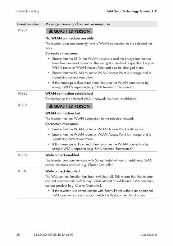
Event number Message, cause and corrective measures10284
No WLAN connection possibleThe inverter does not currently have a WLAN connection to the selected net-work.Corrective measures:• Ensure that the SSID, the WLAN password and the encryption methodhave been entered correctly. The encryption method is specified by yourWLAN router or WLAN Access Point and can be changed there.
• Ensure that the WLAN router or WLAN Access Point is in range and issignalizing correct operation.
• If this message is displayed often, improve the WLAN connection byusing a WLAN repeater (e.g. SMA Antenna Extension Kit).
10285 WLAN connection establishedConnection to the selected WLAN network has been established.
10286
WLAN connection lostThe inverter has lost WLAN connection to the selected network.Corrective measures:• Ensure that the WLAN router or WLAN Access Point is still active.• Ensure that the WLAN router or WLAN Access Point is in range and issignalizing correct operation.
• If this message is displayed often, improve the WLAN connection byusing a WLAN repeater (e.g. SMA Antenna Extension Kit).
10339 Webconnect enabledThe inverter can communicate with Sunny Portal without an additional SMAcommunications product (e.g. Cluster Controller).
10340 Webconnect disabledThe Webconnect function has been switched off. This means that the invertercan not communicate with Sunny Portal without an additional SMA communi-cations product (e.g. Cluster Controller).• If the inverter is to communicate with Sunny Portal without an additionalSMA communication product, switch the Webconnect function on.
8 Troubleshooting SMA Solar Technology America LLC
User ManualSB5.0-6.0-1SP-US-40-BA-en-1050

Event number Message, cause and corrective measures10341 Webconnect error: no connection
It is likely that there is an error in the network settings.Corrective measures:• Check the network components (DLAN, WLAN Access Point etc.).• Ensure that the following ports are not blocked:– Registrar: ied.sma.de:9523– Proxy: ied.sma.de:9523– Stun: stun.sma.de:3478– Domain: ied.sma.de (for SIP URI)
10343 Webconnect error: Default gateway not configuredIt is likely that there is an error in the network settings.Corrective measures:• Check the network components (DLAN, WLAN Access Point etc.).• Ensure that the following ports are not blocked:– Registrar: ied.sma.de:9523– Proxy: ied.sma.de:9523– Stun: stun.sma.de:3478– Domain: ied.sma.de (for SIP URI)
10344 Webconnect error: DNS server not configuredIt is likely that there is an error in the network settings.Corrective measures:• Check the network components (DLAN, WLAN Access Point etc.).• Ensure that the following ports are not blocked:– Registrar: ied.sma.de:9523– Proxy: ied.sma.de:9523– Stun: stun.sma.de:3478– Domain: ied.sma.de (for SIP URI)
10345 No reply to DNS requestIt is likely that there is an error in the network settings.Corrective measures:• Check the network components (DLAN, WLAN Access Point etc.).• Ensure that the following ports are not blocked:– Registrar: ied.sma.de:9523– Proxy: ied.sma.de:9523– Stun: stun.sma.de:3478– Domain: ied.sma.de (for SIP URI)
8 TroubleshootingSMA Solar Technology America LLC
User Manual 51SB5.0-6.0-1SP-US-40-BA-en-10

Event number Message, cause and corrective measures10346 SIP proxy DNS resolution failed
It is likely that there is an error in the network settings.Corrective measures:• Check the network components (DLAN, WLAN Access Point etc.).• Ensure that the following ports are not blocked:– Registrar: ied.sma.de:9523– Proxy: ied.sma.de:9523– Stun: stun.sma.de:3478– Domain: ied.sma.de (for SIP URI)
10347 Stun server DNS resolution failedIt is likely that there is an error in the network settings.Corrective measures:• Check the network components (DLAN, WLAN Access Point etc.).• Ensure that the following ports are not blocked:– Registrar: ied.sma.de:9523– Proxy: ied.sma.de:9523– Stun: stun.sma.de:3478– Domain: ied.sma.de (for SIP URI)
10348 Webconnect error: No reply to request to STUN serverIt is likely that there is an error in the network settings.Corrective measures:• Check the network components (DLAN, WLAN Access Point etc.).• Ensure that the following ports are not blocked:– Registrar: ied.sma.de:9523– Proxy: ied.sma.de:9523– Stun: stun.sma.de:3478– Domain: ied.sma.de (for SIP URI)
8 Troubleshooting SMA Solar Technology America LLC
User ManualSB5.0-6.0-1SP-US-40-BA-en-1052

Event number Message, cause and corrective measures10349 Webconnect error: No reply to SIP option packs
It is likely that there is an error in the network settings or a Sunny Portal mainte-nance message is present.Corrective measures:• If a Sunny Portal maintenance message is present, wait until themaintenance has been completed.
• Check the network components (DLAN, WLAN Access Point etc.).• Ensure that the following ports are not blocked:– Registrar: ied.sma.de:9523– Proxy: ied.sma.de:9523– Stun: stun.sma.de:3478– Domain: ied.sma.de (for SIP URI)
10350 Webconnect error: Registration rejected by SIP registrarIt is likely that there is an error in the network settings.Corrective measures:• Check the network components (DLAN, WLAN Access Point etc.).• Ensure that the following ports are not blocked:– Registrar: ied.sma.de:9523– Proxy: ied.sma.de:9523– Stun: stun.sma.de:3478– Domain: ied.sma.de (for SIP URI)
10351 Unknown SIP registryIt is likely that there is an error in the network settings.Corrective measures:• Check the network components (DLAN, WLAN Access Point etc.).• Ensure that the following ports are not blocked:– Registrar: ied.sma.de:9523– Proxy: ied.sma.de:9523– Stun: stun.sma.de:3478– Domain: ied.sma.de (for SIP URI)
8 TroubleshootingSMA Solar Technology America LLC
User Manual 53SB5.0-6.0-1SP-US-40-BA-en-10

Event number Message, cause and corrective measures10352 Webconnect error: Faulty communication
It is likely that there is an error in the network settings or a Sunny Portal mainte-nance message is present.Corrective measures:• If a Sunny Portal maintenance message is present, wait until themaintenance has been completed.
• Check the network components (DLAN, WLAN Access Point etc.).• Ensure that the following ports are not blocked:– Registrar: ied.sma.de:9523– Proxy: ied.sma.de:9523– Stun: stun.sma.de:3478– Domain: ied.sma.de (for SIP URI)
10353 Webconnect error: registration of the SIP registry has not respondedIt is likely that there is an error in the network settings or a Sunny Portal mainte-nance message is present.Corrective measures:• If a Sunny Portal maintenance message is present, wait until themaintenance has been completed.
• Check the network components (DLAN, WLAN Access Point etc.).• Ensure that the following ports are not blocked:– Registrar: ied.sma.de:9523– Proxy: ied.sma.de:9523– Stun: stun.sma.de:3478– Domain: ied.sma.de (for SIP URI)
27107 Update file OKThe update file is suitable for this inverter and its components and is fully avail-able for the next update step.
27108 Memory card is being readThe storage medium is being read.
27109 No new update on the memory cardA new update file was not found on the storage medium.
27301 Update communicationThe inverter is updating the communication component.
27302 Update main CPUThe inverter is updating the inverter component.
27312 Update completedThe inverter has successfully completed the update.
8 Troubleshooting SMA Solar Technology America LLC
User ManualSB5.0-6.0-1SP-US-40-BA-en-1054

Event number Message, cause and corrective measures27331 Update transport started
The inverter has successfully started the update.
27332 Update transport successfulThe update file has been successfully transferred to the communication compo-nent.
29001 Inst. code validThe entered Grid Guard code is valid. Protected parameters have now beenunlocked and you can adjust the parameters. The parameters will be automati-cally locked again after ten feed-in hours.
29004 Grid parameters unchangedChanging the grid parameters is not possible.
8.3 Checking the PV System for Ground Faults
If the inverter displays the event numbers 3501, 3601 or 3701, there could be a ground fault. Theelectrical insulation from the PV system to ground is defective or insufficient.
Danger to life due to electric shockIn the event of a ground fault, high voltages can be present.• Touch the cables of the PV array on the insulation only.• Do not touch any parts of the substructure or frame of the PV array.• Do not connect PV strings with ground faults to the inverter.
Destruction of the measuring device due to overvoltage• Only use measuring devices with a DC input voltage range of 600 V or higher.
Procedure:In order to check the PV system for ground faults, perform the following actions in the prescribedorder. The exact procedure is described in the following sections.• Check the PV system for ground faults by measuring the voltage.• If the voltage measurement was not successful, check the PV system via insulation resistancemeasurement for ground faults.
Test by Measuring the VoltageProceed as follows to check each string in the PV system for ground faults.
8 TroubleshootingSMA Solar Technology America LLC
User Manual 55SB5.0-6.0-1SP-US-40-BA-en-10

Procedure:1.
Danger to life due to high voltages• Disconnect the inverter from any voltage sources (see the inverter installation manual).
2. Measure the voltages:• Measure the voltage between the positive terminal and the ground potential (PE).• Measure the voltage between the negative terminal and the ground potential (PE).• Measure the voltage between the positive and negative terminals. If the following results are present at the same time, there is a ground fault in the PVsystem:☑ All measured voltages are stable.☑ The sum of the two voltages to ground potential is approximately equal to thevoltage between the positive and negative terminals.
• If a ground fault is present, determine the location of the ground fault via the ratio of thetwo measured voltages and eliminate the ground fault.
Example: Location of the ground faultThe example shows a ground fault between the second and third PV module.
3. If a definite ground fault cannot be measured and the message is still displayed, measure theinsulation resistance.
4. Reconnect the strings without ground faults to the inverter and recommission the inverter (seeinverter installation inverter).
8 Troubleshooting SMA Solar Technology America LLC
User ManualSB5.0-6.0-1SP-US-40-BA-en-1056

Test by Measuring the Insulation ResistanceIf the voltage measurement does not provide sufficient evidence of a ground fault, the insulationresistance measurement can provide more exact results.
Figure 4: Schematic diagram of the measurement
Calculating the insulation resistanceThe expected total resistance of the PV system or of an individual string can be calculatedusing the following formula:
total
The exact insulation resistance of a PV module can be obtained from the module manufactureror the datasheet.For the resistance of a PV module an average value can be assumed: for thin-film PV modulesapproximately 40 MOhm and for polycrystalline and monocrystalline PV modulesapproximately 50 MOhm per PV module (for further information on calculating the insulationresistance see the Technical Information "Insulation Resistance (Riso) of Non-GalvanicallyIsolated PV Systems" at www.SMA-Solar.com).
Required devices:☐ Suitable device for safe disconnection and short-circuiting☐ Measuring device for insulation resistance
Device required for safe disconnection and short-circuiting of the PV arrayThe insulation resistance can only be measured with a suitable device for safe disconnectionand short-circuiting of the PV array. If no suitable device is available, the insulationmeasurement must not be carried out.
Procedure:1. Calculate the expected insulation resistance per string.2.
Danger to life due to high voltages• Disconnect the inverter from any voltage sources (see the inverter installation manual).
3. Install the short circuit device.
8 TroubleshootingSMA Solar Technology America LLC
User Manual 57SB5.0-6.0-1SP-US-40-BA-en-10

4. Connect the measuring device for insulation resistance.5. Short-circuit the first string.6. Set the test voltage. The test voltage should be as close as possible to the maximum systemvoltage of the PV modules but must not exceed it (see datasheet of the PV modules).
7. Measure the insulation resistance.8. Eliminate the short circuit.9. Measure the remaining strings in the same manner.☑ If the insulation resistance of a string deviates considerably from the theoreticallycalculated value, there is a ground fault present in that string.
10. Reconnect to the inverter only those strings from which the ground fault has been eliminated.11. Reconnect all other strings to the inverter.12. Recommission the inverter (see inverter installation manual).13. If the inverter still displays an insulation error, contact the Service (see Section 11 "Contact",page 63). The PV modules might not be suitable for the inverter in the present quantity.
8.4 Resetting the Operation Inhibition after Detection of anArc Fault
If the red LED is glowing and the event number 4301 is shown on the display and/or in the eventlist on the user interface of the inverter, the inverter has detected an electric arc and interrupts feed-in operation.There are two options for resetting the operation inhibition:• Reset the operation inhibition by tapping twice on the enclosure lid of the Connection Unit.• Reset the operation inhibition by parameter setting.
Reset the operation inhibition by tapping twice on the enclosure lid of theConnection Unit1.
Danger to life due to electric shock• Disconnect the inverter from any voltage sources (see the inverter installation manual).
2. Ensure that the PV modules, the connected DC cables and the connecting terminal plate for theDC connection are not defective.Repair or replace defective PV modules, DC cables or connecting terminal plate for the DCconnection.
8 Troubleshooting SMA Solar Technology America LLC
User ManualSB5.0-6.0-1SP-US-40-BA-en-1058

3. Recommission the inverter (see inverter installation manual).4. If the event with the event number 4301 appears in the display, immediately tap on theenclosure lid twice in quick succession. Here, the operation inhibition can only be reset if theevent is showing in the display when you begin tapping.
☑ This effects resetting of the operation inhibition and the inverter will start feeding in again. Atthe same time, the blue LED can flash rapidly, indicating that there is an active WPS function.The WPS function deactivates automatically after a short period.
Reset the operation inhibition by parameter setting1.
Danger to life due to electric shock• Disconnect the inverter from any voltage sources (see the inverter installation manual).
2. Ensure that the PV modules, the connected DC cables and the connecting terminal plate for theDC connection are not defective.Repair or replace defective PV modules, DC cables or connecting terminal plate for the DCconnection.
3. Recommission the inverter (see inverter installation manual).4. Activate the user interface (see Section 5.1, page 19).5. Log into the user interface as an Installer (see Section 5.2, page 22).6. Reset the operation inhibition by setting one of the following parameters:• Select the parameter Reset operating data and set to Reset operation inhibition.
or• Select the parameter AFCI switched on and set to No and then back to Yes.
☑ This effects resetting of the operation inhibition and the inverter will start feeding in again.
8.5 Updating the Firmware
If no automatic update is set in the communication product (e.g. Cluster Controller) or via the userinterface of the inverter, you have two possibilities to update the inverter firmware:• Updating firmware via the user interface of the inverter.• Updating the firmware via USB flash drive.
Updating firmware via the user interface
Requirement:☐ An update file with the desired inverter firmware must be available. The update file is, forexample, available for download on the product page of the inverter at www.SMA-Solar.com.
Procedure:1. Activate the user interface (see Section 5.1, page 19).2. Log into the user interface (see Section 5.2, page 22).3. Select the menu System Configuration.
8 TroubleshootingSMA Solar Technology America LLC
User Manual 59SB5.0-6.0-1SP-US-40-BA-en-10

4. Select [Settings].5. In the context menu, select [Updating the firmware].6. Follow the instructions in the dialog.
Updating the firmware via USB flash drive.
Requirement:☐ A USB flash drive with maximum 32 GB and file system FAT32 must be available.
Procedure:1. Create an "UPDATE" folder on the USB stick.2. Save the update file with the desired firmware in the "UPDATE" folder on the USB flash drive.The update file is, for example, available for download on the product page of the inverter atwww.SMA-Solar.com.
3.
Danger to life due to high voltages• Disconnect the inverter from any voltage sources and open the enclosure lid of theConnection Unit (see the inverter installation manual).
4. Insert the USB flash drive in the USB port on the communication assembly.5. Commission the inverter (see inverter installation manual).☑ During start-up phase of the inverter, the desired firmware is being installed. At the sametime, the status of the update is shown in the display: Update status: xxxxxxx
☑ Once the desired firmware has been installed in the inverter, the status successful isshown in the display.
✖ The status error occurred is shown in the display?The firmware update was not successful.• Update the firmware again.
6.
Danger to life due to high voltages• Disconnect the inverter from any voltage sources again and open the enclosure lid of theConnection Unit (see the inverter installation manual).
7. Pull the USB flash drive out of the USB port.8. Commission the inverter (see inverter installation manual).
8 Troubleshooting SMA Solar Technology America LLC
User ManualSB5.0-6.0-1SP-US-40-BA-en-1060

9 AccessoriesYou will find the accessories for your product in the following overview. If required, these can beordered from SMA or your distributor.
Designation Short designation SMA order numberSMA Sensor Module Multi-function interface for one SMA in-
verter as retrofit kit for capturing environ-mental data (e.g. irradiation, ambient tem-perature, cell temperature, wind speed orS0 meters).
MD.SEN-US-40
SMA Antenna Exten-sion Kit
Accessory set for one SMA inverter for theoptimization of the SMA inverter’s WLANradio range.
EXTANT-US-40
9 AccessoriesSMA Solar Technology America LLC
User Manual 61SB5.0-6.0-1SP-US-40-BA-en-10

10 Compliance InformationFCC ComplianceThis device complies with Part 15 of the FCC Rules. Operation is subject to the following conditions:1. This device may not cause harmful interference, and2. This device must accept any interference received, including interference that may causeundesired operation.
NOTE: This equipment has been tested and found to comply with the limits for a Class B digitaldevice, pursuant to Part 15 of the FCC Rules. These limits are designed to provide reasonableprotection against harmful interference in a residential installation. This equipment generates, uses,and can radiate radio frequency energy and if not installed and used in accordance with theinstructions, may cause harmful interference to radio communications. However, there is noguarantee that interference will not occur in a particular installation. If this equipment does causeharmful interference to radio or television reception, which can be determined by turning theequipment off and on, the user is encouraged to try to correct the interference by one or more ofthe following measures:• Reorient or relocate the receiving antenna.• Increase the separation between the equipment and the receiver.• Connect the equipment into an outlet on a circuit different from that to which the receiver isconnected.
• Consult the dealer or an experienced radio/TV technician for help.The user is cautioned that changes or modifications not expressly approved by SMA SolarTechnology America LLC could void the user’s authority to operate this equipment.
IC ComplianceThis Class B digital apparatus complies with Canadian ICES-003.Cet appareil numérique de la classe B est conforme à la norme NMB-003 du Canada.
10 Compliance Information SMA Solar Technology America LLC
User ManualSB5.0-6.0-1SP-US-40-BA-en-1062

11 ContactIf you have technical problems with our products, please contact the SMA Service Line. We needthe following information in order to provide you with the necessary assistance:• Inverter device type• Inverter serial number• Inverter firmware version• Special country-specific settings of the inverter (if applicable)• Type and number of PV modules connected• Mounting location and altitude of the inverter• Inverter message• Optional equipment, e.g. communication products• If necessary system name in the Sunny Portal• If necessary access data in the Sunny Portal• Operating mode of the multifunction relay
UnitedStates/ Esta-dos Unidos
SMA Solar TechnologyAmerica LLCRocklin, CA
Toll free for USA, Canada and Puerto Rico / Llamada gra-tuita en EE. UU., Canadá y Puerto Rico:+1 877-MY-SMATech (+1 877-697-6283)International / Internacional: +1 916 625-0870
Canada/Canadá
SMA Solar TechnologyCanada Inc.Mississauga
Toll free for Canada / gratuit pour le Canada:+1 877-MY-SMATech (+1 877-697-6283)
11 ContactSMA Solar Technology America LLC
User Manual 63SB5.0-6.0-1SP-US-40-BA-en-10

www.SMA-Solar.com