Embed Size (px)
Citation preview

SP16 SERIES PROGRAMMER
USER MANUAL Revision B5
Before using the programmer, please read this manual carefully and operate the programmer correctly as required. Failure to follow the instructions will result in damage to the programmer and no warranty service!
深 圳 硕 飞 科 技 有 限 公 司 SHENZHEN SOFI TECHNOLOGY CO.,LTD.
WEB: WWW.SOFI-TECH.COM
硕飞科技

硕飞科技
SHENZHEN SOFI TECHNOLOGY www.sofi-tech.com
User Manual
2
SP16 Series programmer
Contents
Chapter1. Introduction into Products 3
Performance and Characters 3
Correlation Table of SP16 Performance 4
Chapter 2. Programmer Hardware 5
Chapter 3. Quick start 6
Programming steps for on-line mode 6
LED status for On-line programming mode 8
Chapter 4. Off-line programming 10
Download Off-line Data 10
Off-line Operation - Manual Mode 12
Off-line Operation - Automatic Control Mode 12
ATE interface definitions 12
LED status for off-line programming mode 12
View Off-line Data 13
Chapter 5. ISP Programming 14
Use ISP programming mode 14
ISP Interface 14
ISP cable 14
Target devices connections 15
ISP Power supply mode 16
Chapter 6. FlyPRO MCP multi-machine control software 17
Function Introduction 17
Usage Instruction 17
FlyPRO_MCP function limitations 19
About USB hub 19
Appendix I FAQ20
Appendix II Disclaimer 22
Appendix III Revision history 23

硕飞科技
SHENZHEN SOFI TECHNOLOGY www.sofi-tech.com
User Manual
3
SP16 Series programmer
Chapter 1. Introduction into Products
Performance and characters
⚫ Designed specifically for serial EEPROM / SPI FLASH device, faster and more stable than general-
purpose programmer
⚫ USB power supply and communication, no external power supply required. Small size (size:
103x71x23mm), easy to carry
⚫ Supports a full range of 93/24/25/BR90 memories, supports software upgrades to increase support for
new devices
⚫ Supports detection of 25 series SPI FLASH device models;
⚫ Supports pin contact detection to improve the reliability of programing;
⚫ Supports ISP program. On-board patch devices can be directly connected to be programmed
⚫ Standard 40Pin ZIF socket, applicable to wide/narrow devices and general adapters
⚫ Overcurrent protection function to effectively prevent misplaced or destroyed device’s effects on the
programmer;
⚫ Programmer has a built-in 32-bit high-speed processor that provides high-speed programming and
precise timing;
⚫ Supports off-line programming without connecting computers. Has a large data memory built-in that can
supports up to 512Mbit device to program off-line (Note 1);
⚫ Mass production programming mode, automatic detection of device placement and start programming
operation;
⚫ ATE interface function that supports automatic programming machine to control (Note 2);
⚫ Supports one computer to connect multiple programmers programming at the same time, one computer
can connect up to 8 programmers
⚫ The buzzer present voice prompt for success or failure
⚫ Programmable voltage design, adjustable from 1.7V to 5.0V, supporting 1.8V/2.5V/3V/3.3V/5V devices;
⚫ Provide device self-test function;
⚫ Support WinXP (SP2), VISTA, Win7/Win8/Win10 (32bit/64bit)
Note 1: Off-line operation is limited to SP16-F, SP16-FX mode; off-line program does not support ISP mode
Note 2: SP16-FX mode only

硕飞科技
SHENZHEN SOFI TECHNOLOGY www.sofi-tech.com
User Manual
4
SP16 Series programmer
Correlation table of SP16 performance
SP16 Series includes three models, and their comparisons of functions are as follows:
Model SP16-FX SP16-F SP16-B
maximum capacity of Supported
devices 512Mb
Supported device voltage programmable voltage adjustable from 1.7V to 5.0V , supports
1.8V/2.5V/3V/3.3V/5V...
Off-line programming (Note 1) Y Y N
Built-in memory for off-line data 512Mb -
On-line mass production (Note 1) Y (automatic detection device placement/removal)
Multi connection (Note 2) Y
Auto serial number Y (On-line program mode only)
Buzzer prompt Y (off-line mode only) N
Overcurrent/short circuit protection Y
ZIF Socket ARIES
ISP programming Support 24/93/25 series (clock adjustable)
OTP area read and write (Note 3) support
Device configuration (Note 3) support
Automatic programing Machine
Support (ATE) Y N N
programing
speed
(Note 4)
GD25Q16(SOP8) Off-line P+V=6S; on-line P+V=7S
W25Q128FV(SOP8) Off-line P+V=47S; on-line P+V=52S
MX25L12845E(SOP16) Off-line P+V=62S; on-line P+V=68S
off-line data download speeds 41S@128Mb -
Support the number of devices
(Note 5) 10284 10284
Note 1: Off-line programming means the model can program without computer, suitable for mass production.
On-line mass production refers to connecting to a computer for batch programming.
Note 2: One computer can maximum connect eight SP16 series programmers (need to work together with
FlyPRO_MCP software, search Chapter 6 for specific usage);
Note 3: Depending on the software function, not all the devices are supported;
Note 4: The programming speed is tested by the complete device random number, “P” is programming, V “is”
verification;
Note 5: Based on FlyPRO software version V4.48 (2019-05-29). The devices will increase with software
upgrades. The number in the table is for reference only. Please download the latest supported
software from Sofi official website download center.

硕飞科技
SHENZHEN SOFI TECHNOLOGY www.sofi-tech.com
User Manual
5
SP16 Series programmer
Chapter 2. Programmer hardware
Programmer
Accessories
USB Cable ISP Cable 5V/1A Power adapter
⚫ The appearance of different models and batches may vary, please refer to the actual
product;
⚫ The power adapter is used to power the programmer during offline programming, and
only SP16-F/SP16-FX which supports offline programming has equipped ;
⚫ The programmer is equipped with a device adapter (IC socket) as standard, please
choose according to your needs.
USB Interface
ZIF Socket
PWR(Power)
STA(State)
ISP/ATE Interface

硕飞科技
SHENZHEN SOFI TECHNOLOGY www.sofi-tech.com
User Manual
6
SP16 Series programmer
Chapter 3. Quick start
Programming steps for on-line mode
1. Install programmer control software: FlyPRO (Includes USB driver, single control software FlyPRO,
multi-control software FlyPRO), software download website: www.sofi-tech.com
2. Connect programmer to USB port of computer with a USB cable.
3. Run the single control software FlyPRO ,the programmer hardware will be automatically connected after
the software starts. After the connection is successful, the software status bar will display the
programmer mode and product serial number, and then you can program devices.
The following takes a device W25Q32BV packaged of SOIC8 (208mil) as an example to introduce the
steps of programming devices:
4. Click the toolbar button ,or menu [Device] - [Select Device], open the "Select Device"
dialog box, select the device model to be programmed and the corresponding package
"W25Q32BV[SOIC8]". You can quickly find the device by entering the device model keyword through the
search box.
Connect to computer USB port
NOTE:
The “W25Q32BV” in the device list
does not have a “[ ]” suffix,
indicating that the model is an DIP
device;
"[SOIC8]", "[SOIC16]", "[WSON8
8x6]", "[WSON8 6x5]", etc. indicate
the package type of device;
“[ISP]” means to use ISP mode to
program, please refer to “Chapter
5. ISP programming”.

硕飞科技
SHENZHEN SOFI TECHNOLOGY www.sofi-tech.com
User Manual
7
SP16 Series programmer
5. Load programming file
Click toolbar button ,or menu [File] - [Load File] to load the data file of program.
6. Set operation options
Click the toolbar button , or menu [Operation] - [Operational Options] to device
programming settings. In most cases, you can use the default settings. For details on the operation
options, please refer to the helper topic of the programmer software.
7. Place device to ZIF Socket
The DIP packaged device can be directly inserted, and the non-straight-inserted device needs to be
matched with IC socket. In this example, an SOP8 wide-body programing seat is used. First, lift ZIF
Socket’s handle, insert the bottom side of IC socket into the bottom of ZIF Socket, press the handle, and
then put the device into IC socket. Pay attention to the direction of the first leg of device.
Physical map Device pin position diagram
For other devices’ placement (including IC socket information), please open the device information in the
FlyPRO software for viewing. Most of 8-pin devices are inserted into ZIF Socket according to the
corresponding relationship on the right. A very small number of devices are placed in a special way.
Please pay attention to the prompts that the software pops up.
Note: ZIF Socket is only used to place the device to be programmed (including IC socket). It is forbidden
to programming devices which have already been welded on circuit board, through wires from ZIF
socket. The peripheral circuit on the board will cause the operation to fail. Serious conditions can cause
permanent damage to the programmer hardware. The manufacturer is not responsible for any
consequences that may result from this incorrect operation. The EMI method is recommended for the
device that has been soldered. Please refer to "Chapter 5. ISP Programming".
8. Perform programming
There are three modes for programming, including manual mode, automatic mode, and automatic mass
production mode. Choose one of the modes to operate according to different situations.
Manual mode
Select the "Manual Operation" page in the command bar on the left side of the main software window.
Follow the typical operation steps according to the device type.
Pin1 Pin1

硕飞科技
SHENZHEN SOFI TECHNOLOGY www.sofi-tech.com
User Manual
8
SP16 Series programmer
Automatic mode
Select the "Automatic Programming" page in the command bar on the left side of the main software
window. First set the operation content, and then click the "single program" button. The programmer
then performs the steps set in "Operational Content" to complete programming process of one device.
Typical steps:
➢ Program SPI FLASH (25 series): Erase → check space →program → check
➢ Program SPI FLASH (25 series, brand new blank device): Program → check
➢ Program I2C EEPROM (24 Series): Program → Verify
➢ Read device data and save it to file: Read → Verify → Save
Production mode
After clicking “Production Programming” button, the programmer automatically detects the placement
and removal of the device and automatically completes the steps in “Operational Content”. The software
pops up a message box to remind users to pick and place devices. It is convenient and quick to program
without using mouse or any buttons.
LED status for on-line programming mode
Power LED (PWR):
A long red light indicates that the power supply is normal, and a red flash indicates that the programmer has
detected a device short circuit or excessive current.

硕飞科技
SHENZHEN SOFI TECHNOLOGY www.sofi-tech.com
User Manual
9
SP16 Series programmer
Status LED (STA):
STA LED status Status description
Orange Programming device
Green Device programming completed, programming successfully
Red Device programming failed
● The above operation is only a demonstration of the conventional programming steps
of the general device,and the specific operation needs to be determined according
to actual needs.
● For detailed instructions on using the software, please refer to the help topic of FlyPRO software.

硕飞科技
SHENZHEN SOFI TECHNOLOGY www.sofi-tech.com
User Manual
10
SP16 Series programmer
Chapter 4. Off-line Programing
SP16-F、SP16-FX supports off-line program. In this mode, programmers don't have to be connected to a
computer. Programmer has a built-in 128Mbit data memory, eliminating the need for additional storage. Off-
line program is easy and efficient. In this mode, programmers automatically detect the placement of devices,
start programming, and present results via state lights and a built-in buzzer.
Off-line mode includes two methods: manual operation and automatic control:
In manual operation mode, programmer automatically detects placement and removal of device. Indicates
working status and programming result through state lights and built-in buzzer.
In automatic control mode, connecting to automatic control machine through ISP/ATE multi-function
interface which controls its function and outputs corresponding indication signals.
SP16-F supports off-line manual mode only; SP16-FX supports two modes above, and it can be operated by
any one of them through software settings.
Download off-line data
Before off-line operation, you must download off-line data into programmer by using computer in advance.
The data download operation steps are as follows:
1. First connect programmer to computer with a USB cable and then turn on the FlyPRO software.
2. Select the correct device model.
3. Load files that need to program.
4. Click the menu [Device] - [Off-line Data Management] - [Download Off-line Data] to open off-line data
download
dialog box and download off-line data. As shown below:

硕飞科技
SHENZHEN SOFI TECHNOLOGY www.sofi-tech.com
User Manual
11
SP16 Series programmer
Controlled by ISP/ATE interface
This option can be used only in SP16-FX. When this function is checked, SP16-FX works in the automatic
control mode and works with automatic machine.
If this function is not checked, SP16-FX works in manual mode.
Erase option
This feature is currently supported by SP16-F/SP16-FX and available for FLASH class devices only.
In order to reduce time of erase options, it can be used to set operation mode when operation content box
contains erase option.
Forced Erase: Always erase the device in its entirety
Non-empty erase: Perform erase operation when the device is not blank. The programmer will first perform
a blank check on the device. The erase operation will be performed only if it is not blank. If the device is
already blank, the erase operation will not be performed.
Device Type /Operation Content setting /Erase Option
Device Type Operation Content setting Erase Option
All blank FLASH devices program→check -
All non-blank FLASH devices erase→program→check Forced erase
Blank device mixed with non-blank
device erase→program→check Non-empty erase
Note: When there is no "Erase" item in the action content box, the erase option does not need to be set
and it will be disabled in gray. It is enabled only if there is an erase item in the action content.
For other setting options, please refer to the help topic of FlyPro software.
5. Disconnect the USB cable between computer and programmer after completing off-line data download, and
then programmer can work independently from the computer.
Off-line operation - manual mode
The steps for the programmer to operate off-line are as follows:
1. Power the programmer with the power adapter that came with the product.
2. After the programmer is powered on, the internal off-line data will be checked to verify that the data is
complete and accurate.
This takes 3 to 25 seconds. STA indicator will flash green if the test passes, indicating that the
programmer has entered to off-line programming mode. STA displays a red flashing state if the test fails, i
ndicating that there is no valid off-line data in the programmer, and off-line programming cannot be started.
3. The programmer's STA indicator flashes green to indicate that it is waiting for the device to be placed.
4. STA stops flashing and being orange indicates that the programmer has detected the device and is
programming.
5. STA displays green or red indicates that device is programmed. Green indicates successful, and red
indicates failed. At the same time, the programmer begins to wait for the current device to be removed
from
ZIF Socket. If the buzzer prompt function is turned on, programmer will make sounds when programming
is completed.
6. After detecting the device removal, programmer repeats steps 3 through 5 to program next device.

硕飞科技
SHENZHEN SOFI TECHNOLOGY www.sofi-tech.com
User Manual
12
SP16 Series programmer
Off-line operation – automatic control mode
The automatic control mode is only applicable to SP16-FX, which is used to cooperate with automatic
equipment such as automatic programming machine and robot to realize automatic operation of devices.
When downloading off-line data, check the "Control via ISP/ATE interface" option to enable this feature. In
this mode of operation, the programmer's ATE interface provides a START enable signal, and OK / NG /
BUSY indicator.
ATE Interface definitions
LED status for off-line programming mode
STA LED status Status description (Manual mode) Status description(Automatic control
mode, SP16-FX only)
Flashing red The programmer did not download
off-line data
The programmer did not download off-
line data
Flashing green Waiting for device placement <no status>
Orange Programming device Programming device
Green
Device programming completed,
programming successfully
(Waiting for device removal)
Device programming completed,
programming successfully
Red Device programming failed
(waiting for device removal) Device programming failed
3--BUSY 5--OK 9--NG
7--START 2—VCC 4/6/8/10--GND
硕飞科技
SHENZHEN SOFI TECHNOLOGY www.sofi-tech.com
User Manual
13
SP16 Series programmer
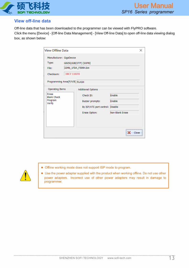
View off-line data
Off-line data that has been downloaded to the programmer can be viewed with FlyPRO software.
Click the menu [Device] - [Off-line Data Management] - [View Off-line Data] to open off-line data viewing dialog
box, as shown below:
● Offline working mode does not support ISP mode to program.
● Use the power adapter supplied with the product when working offline. Do not use other
power adapters. Incorrect use of other power adapters may result in damage to
programmer.

硕飞科技
SHENZHEN SOFI TECHNOLOGY www.sofi-tech.com
User Manual
14
SP16 Series programmer
Chapter 5. ISP Programing
The ISP is called In System Program, which is on-line programming. The ISP programming mode only
needs to connect several signal lines to the relevant pins of the onboard device to be read and written,
which can eliminate the trouble of removing and soldering devices.
Use ISP programming mode
The SP16 series programmer only supports ISP mode programming of some devices. When the device
model with the "[ISP]" suffix is selected in the software, it means that ISP mode is used for programming.
(Selecting the device mode without ISP suffix, you can only program it through ZIF Socket. Do not select
wrong mode for both programming methods.)
Note: ISP program should use a dedicated ISP interface to connect, do not connect through wires from ZIF
socket.
ISP interface
The SP16 Series Programmer provides an additional ISP interface as shown below:
ISP/ATE interface ISP interface definiens
ISP Cable The ISP cable is a 10-color color cable with a 5x2 standard plug on one end and access to the
programmer's ISP/ATE interface. The other end is 10 DuPont connectors that are connected to the
corresponding pins on the target board. The following figure shows the BIOS upgrade for the ASUS
motherboard with SPI interface reserved.
ISP/ATE接口
19 7 5 3
210 8 6 4
接口引脚图

硕飞科技
SHENZHEN SOFI TECHNOLOGY www.sofi-tech.com
User Manual
15
SP16 Series programmer
The correspondence between the color of the connecting line and the pin number is as follows:
Color Pin number Color Pin number
brown 1 Blue 6
Red 2 purple 7
Orange(or pink) 3 Gray 8
Yellow 4 White 9
Green 5 Black 10
Target device connections
Common 25 series and 93/24 series FLASH/EEPROM connection diagrams are as follows
Typical 25 series FLASH connection diagrams Typical 93 series EEPROM connection diagrams
Typical 24 series EEPROM connection diagrams
NOTE:
Different devices will have different connection
methods.
For detailed connection information of the
device, please open the device information in
FlyPRO software for viewing.
硕飞科技
SHENZHEN SOFI TECHNOLOGY www.sofi-tech.com
User Manual
16
SP16 Series programmer
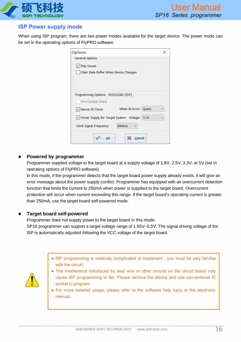
ISP Power supply mode
When using ISP program, there are two power modes available for the target device. The power mode can
be set in the operating options of FlyPRO software.
⚫ Powered by programmer
Programmer supplies voltage to the target board at a supply voltage of 1.8V, 2.5V, 3.3V, or 5V (set in
operating options of FlyPRO software).
In this mode, if the programmer detects that the target board power supply already exists, it will give an
error message about the power supply conflict. Programmer has equipped with an overcurrent detection
function that limits the current to 250mA when power is supplied to the target board. Overcurrent
protection will occur when current exceeding this range. If the target board's operating current is greater
than 250mA, use the target board self-powered mode.
⚫ Target board self-powered
Programmer does not supply power to the target board in this mode.
SP16 programmer can support a target voltage range of 1.65V~5.5V. The signal driving voltage of the
ISP is automatically adjusted following the VCC voltage of the target board.
● ISP programming is relatively complicated to implement , you must be very familiar
with the circuit;
● The interference introduced by lead wire or other circuits on the circuit board may
cause ISP programming to fail. Please remove the device and use conventional IC
socket to program.
● For more detailed usage, please refer to the software help topic or the electronic
manual.

硕飞科技
SHENZHEN SOFI TECHNOLOGY www.sofi-tech.com
User Manual
17
SP16 Series programmer
Chapter 6. FlyPRO MCP multi-machine control software
Function Introduction ● FlyPRO MCP is the multi-machine control software of SOFI SP16 series programmer
● Up to 8 programmers can be connected to a single computer
● Can support 8 programmers to work at the same time, including: automatic programming (single), mass
production programming, download off-line data (SP16-F/SP16-FX)
● Support the management of project files
Usage Instruction
Step 1: Install multi-machine application
Starting in 2016-10-10, FlyPRO installation package includes SP16 series of multi-machine operating
software (FlyPRO MCP), If it has been installed, Skip step 1.
● Download FlyPRO programmer software (SP8 series/SP16 series) from SOFI official website:
www.sofi-tech.com
● Unzip the downloaded file and install it
Step 2: Connect multiple SP16 programmers to the computer using a USB hub
硕飞科技
SHENZHEN SOFI TECHNOLOGY www.sofi-tech.com
User Manual
18
SP16 Series programmer
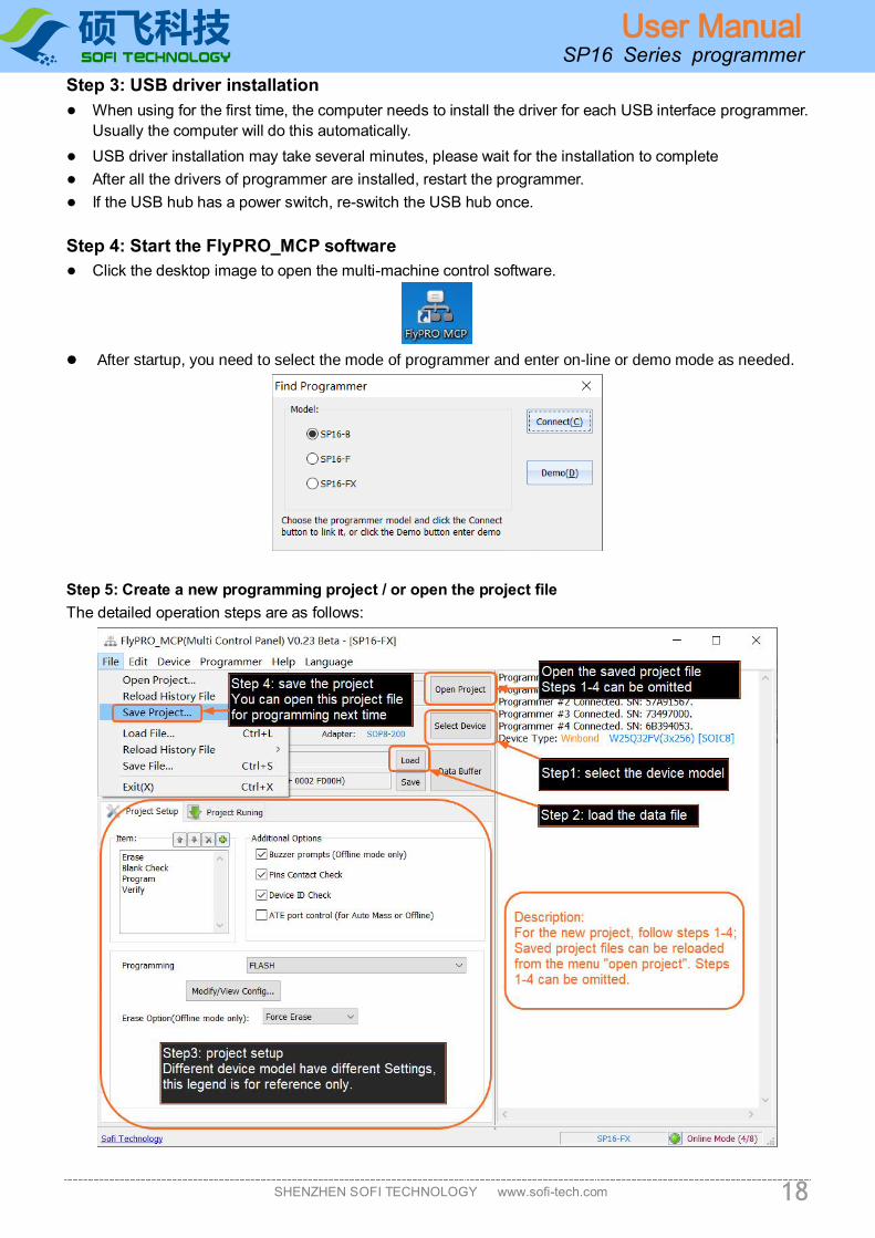
Step 3: USB driver installation
● When using for the first time, the computer needs to install the driver for each USB interface programmer.
Usually the computer will do this automatically.
● USB driver installation may take several minutes, please wait for the installation to complete
● After all the drivers of programmer are installed, restart the programmer.
● If the USB hub has a power switch, re-switch the USB hub once.
Step 4: Start the FlyPRO_MCP software
● Click the desktop image to open the multi-machine control software.
⚫ After startup, you need to select the mode of programmer and enter on-line or demo mode as needed.
Step 5: Create a new programming project / or open the project file
The detailed operation steps are as follows:

硕飞科技
SHENZHEN SOFI TECHNOLOGY www.sofi-tech.com
User Manual
19
SP16 Series programmer
Step 6: Action
FlyPRO_MCP function limitations
Compared to the standard stand-alone software FlyPRO, the following functions are not supported in multi-
machine software.
● Automatic serial number
● Manual operation (multi-machine software only supports automatic programming, mass production
programming and off-line data download)
● Programmer device self-test
● Programmer firmware upgrade
● Pin contact failure prompt (multi-machine software will directly report error and terminate the operation
when pin contact is poor)
● Test device mode
● View off-line information in the programmer
To apply the above information, please use the standard stand-alone software FlyPRO
About USB hub
● To ensure performance, please use a USB hub with an external power supply.
● It is recommended to use USB3.0 hub.

硕飞科技
SHENZHEN SOFI TECHNOLOGY www.sofi-tech.com
User Manual
20
SP16 Series programmer
Appendix I FAQ
☺ Why 24 series device does not have an erase function
◼ The device is based on EEPROM technology, device data can be directly rewritten without pre-
erasing, so there is no erase operation available.
◼ If you want to clear the device data, please write FFH data directly to the device.
☺ What is the reason for the software prompt device initialization error?
When programming some devices (such as 24 series devices), the programmer will perform initialization
detection on the device. The error will be prompted if the detection fails. Device initialization errors usually
have the following reasons:
◼ The device is not placed on ZIF Socket, or the device pins are not in contact.
◼ Device placement direction or position error
◼ There is a problem with the device itself
◼ The device mode does not match (the model selected in the software is different from the actual
placement on the lock seat)
◼ ISP connection line problem (ISP mode only, device with [ISP] suffix)
☺ Why the programmed device cannot work properly?
The programmed device does not work properly for the following reasons:
◼ The data file was not loaded correctly before the device was programmed
◼ There is a problem with the data file itself
◼ Programming operation steps are wrong
◼ Device working circuit / voltage problem
☺ Is it possible to program devices which have already been welded on circuit board through wires
from ZIF socket?
No. The ZIF Socket is only used to place the device to be programmed (including IC socket). It is forbidden
to operate the device soldered on the circuit board through wires from ZIF socket. The peripheral circuit
on the board will cause the operation to fail and result in permanent damage to the programmer hardware.
Manufacturer is not responsible for any consequences that may result from this incorrect operation. The
EMI method is recommended for the device that has been soldered. Please refer to "Chapter 5 ISP
Program".
☺ Can img file be programming?
The file encoding format supported by the programmer software is binary and hexadecimal (Inter HEX),
the binary file is suffixed with *.bin, and the hex file is suffixed with *.hex.
Img is just a file suffix, does not represent the file encoding format, usually (90% or more) such files are
binary coded, can be loaded directly in the software. The software automatically recognizes whether the
file is binary encoded and loads it in the recognized format.
In order to ensure the accuracy of file loading, we recommend that users check the buffer checksum and
file checksum with the engineering technician (or file code provider/customer, etc.) after loading such files.
The information will be displayed below the main window of program software).

硕飞科技
SHENZHEN SOFI TECHNOLOGY www.sofi-tech.com
User Manual
21
SP16 Series programmer
☺ How should the device configuration bit be set?
All configuration options of the device are listed according to the specifications of the device manufacturer.
The programmer is only responsible for writing data set by users to devices. The programmer’s
manufacturer cannot tell users how to set it. Please contact the project engineer/code provider.
Configuration options are implemented by “write configuration”. In automatic programming (including off-
line operation/machine operation), the write configuration needs to be added to the last step of the
operation, for example: “programming” “verification” “write configuration”
☺ Part of programmed devices that soldered to the product cannot be run. But it can be run when
remove it and re-program again. Is it because programmer does not program devices correctly?
During the final test of the product, it was found that some of the data in device was wrong/or lost/or empty.
There are several reasons for this, and common situations are as follows:
1. When the product is tested for power, the device data is rewritten or erased due to
interference, power supply instability, abnormal access, software malfunction, etc.
2. Device sorting is confused. < Put the device that failed to program or has not been programmed to
the OK side >
3. The temperature stability of the device is poor, and the data is lost or changed due to high
temperature during soldering.
According to the statistics we have reported, most of the problems are in cases 1 and 2. The case caused
by the programmer is not found.
Programming only guarantees that the device data after programming is correct. For data error that
discovered after high-temperature soldering, power-on operation of the product <device has been
read/written>, is not in the warranty range of the programmer.
If you want to eliminate or verify problems with programmer, it is recommended to check the device 100%
before the patch is soldered.
For Case 1: If the device is SPI FLASH, there is a way to avoid it: Add protection to prevent accidental
erasure to the device when programming it. See http://www.sofi-tech.com/html/6184791048.html
☺ What are the precautions for ISP Program?
ISP program is relatively complicated to implement and is suitable for people with certain professional
knowledge. If only a small number of devices to be program, it is recommended to remove devices from
board, program it with a conventional IC socket, and then solder it back to the motherboard. This may be
more efficient than ISP program. When using ISP program, you must pay attention to the following:
1. Know the target board circuit diagram. <If you have questions about ISP program, you must provide
us with the schematic>
2. When programming target device, it must be ensured that the master device on the board does not
access the target device, and all connected IOs of the master device need to be placed in a high-
impedance state. <Can try to set the master device to RESET state>
3. The line connection should as short as possible. <Some devices may be too long even if you use the
included ISP cable>
4. The IO that is not connected to the device must meet the normal working conditions of the device.
For example: 25 SPI FLASH HOLD and WP pins must be pulled high.
Special Note: ISP program is connected from the ISP interface of programmer (the dedicated 10pin at
the bottom), and select the mode with the [ISP] suffix in software (It means not support if there is no [ISP]
suffix after device mode). Do not connect from the ZIF Socket (40pin socket) through wires.

硕飞科技
SHENZHEN SOFI TECHNOLOGY www.sofi-tech.com
User Manual
22
SP16 Series programmer
Appendix II Disclaimer
Shenzhen SOFI Technology Co., Ltd. will do its utmost to ensure the correctness of the products and related
software and materials. For the possible defects or errors of products (including software and related
materials), the company will try its best to solve with commercial and technical means. The Company shall
not be liable for any incidental, consequential, direct, indirect, special, extended or punitive damages arising
out of the use or sale of the product, including but not limited to profits, goodwill, loss of availability, business
interruption, loss of data, etc., shall not be liable for any direct, indirect, incidental, special, derivative,
punitive damages or third party claims.
硕飞科技
SHENZHEN SOFI TECHNOLOGY www.sofi-tech.com
User Manual
23
SP16 Series programmer
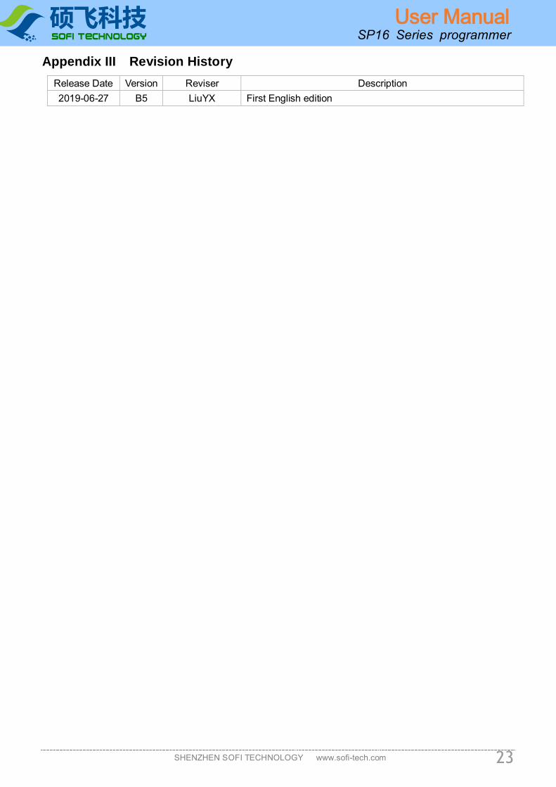
Appendix III Revision History
Release Date Version Reviser Description
2019-06-27 B5 LiuYX First English edition