Embed Size (px)
Citation preview

TAG GD700User Manual
TAG Global Systems

©2018 TAG Global Systems Corporation. All rights reserved. TRADEMARKS
TAG Global Systems logo is a trademark of TAG Global Systems, LLC, registered in the United States Patent and Trademark Office and in other countries. Microsoft and the Windows® logo are either registered trademarks or trademarks of Microsoft Corporation in the United States and/or other countries.
Microsoft products are licensed to OEMs by Microsoft Licensing, Inc., a wholly owned subsidiary of Microsoft Corporation. The Bluetooth® word mark and logos are registered trademarks owned by Bluetooth SIG, Inc. All other brand and product names are trademarks or registered trademarks of their respective owners.
Images shown in this document may vary slightly from actual products at time of shipping. Information in this manual is subject to change without notice.

TABLE OF CONTENTSABOUT THIS MANUAL
Related Information 1
Conventions 1
BASIC SAFETY GUIDELINESIntended Use 2
Unintended Application Use 2
Maintenance and Operation Overview 2
Safety 3
ELECTRICAL HAZARDS 3
Cleaning / Servicing: Power Off the TAG GD700 3
Power Adapter 3
Use only Supplied Power Cables 3
Environmental Hazards 3
Safety Guidelines for Mounting 3
ENVIRONMENTAL 3
Ambient Temperature 3
Connecting and Disconnecting External Devices 4
Only Use Authorized Accessories 4
RADIO TRANSMISSIONS 4
Permitted Transmission Power 4
Radio Frequency Limited Locations 4
CLEANING AND SERVICING 4
REGULATORY AND CERTIFICATION 4
FCC 4
Labeling Requirements 5
RF Exposure Information (SAR) 5
CE Marking 5
R&TTE 5
CB 5
LITHIUM BATTERY SAFETY STATEMENT 6
ii

CHAPTER 1. INTRODUCTIONAbout This Guide 6
Unpacking the Device 6
Technical Specifications 6 -8
TAG GD700 CONFIGURATION OPTIONS 8
Parts List 9
Identifying the Device 10
LED Status 12
Dimensions 15
Touch Screen Features 16
CHAPTER 2. GETTING STARTEDCharging the Battery 17
Powering On the Device 20
Powering Off the Device 20
INSTALLING THE MICRO SIM CARD 20
REMOVING THE MICRO SIM CARD 22
INSTALLING THE MICROSD CARD 25
REMOVING THE MICROSD CARD 26
INSTALLING ON THE VEHICLE DOCK 27
REMOVING FROM THE VEHICLE DOCK 28
INSTALLING ON THE DESKTOP DOCK 29
REMOVING FROM THE DESKTOP DOCK 30
USING THE STYLUS 30
REMOVING THE PROTECTIVE FILM FROM THE DISPLAY 30
CHAPTER 3. OPERATIONREMOVING THE SNAP-ON MODULE CONNECTOR COVER 32
REPLACING THE SNAP-ON MODULE CONNECTOR COVER 33
OPENING THE I/O COMPARTMENT COVER 35
CLOSING THE I/O COMPARTMENT COVER 36
CONNECTING TO EXTERNAL CABLING 37
Connect USB Cabling 37
Connect Ethernet Cabling 37
Connect Audio Cabling 38
iii
Connect RS-232 Cabling 38
HANDSTRAP, CARRYING HANDLE AND SHOULDER STRAP 39
Connecting the Handstrap 39
Removing the Handstrap 40
Connecting the Carrying Handle 40
Removing the Carrying Handle 41
Connecting the Shoulder Strap 42
Removing the Shoulder Strap 43
INSTALLING THE EXTENDED BATTERY 44
REMOVING THE EXTENDED BATTERY 47
MAGNETIC STRIPE READER AND BARCODE SCANNER 50
Installing the Module 50
Removing the Module 51
MAGNETIC STRIPE READER AND MACHINE-READABLE ZONE READER 52
Installing the Module 52
Removing the Module 53
CONNECTING TO A WIRELESS NETWORK 53
PAIRING THE NFC DEVICE 54
CHAPTER 4. USING BIOS SETUP UTILITYWHEN TO USE THE BIOS SETUP UTILITY 55
Accessing the BIOS Setup Utility 55
INSTALLING AN OPERATING SYSTEM 56
Setting Up a Windows™ 10 Installation Environment 56
BIOS PASSWORDS 58
Setting Up a Supervisor Password 58
Changing a Supervisor Password 60
Resetting a Supervisor Password 60
EC AND BIOS 60
Updating BIOS 60
Updating EC 64
iv

CHAPTER 5. USING THE DASHON UTILITYOVERVIEW 65
CHAPTER 6. TROUBLESHOOTINGTROUBLESHOOT THE WI-FI CONNECTION 66
TROUBLESHOOT OPERATING THE COMPUTER 67
CALL PRODUCT SUPPORT 67
CHAPTER 7. MAINTENANCECleaning the Device 68
Housing 68
Touch Screen 68
Returning the Device 68
Contacting TAG Global Systems 68
v

About This ManualThe TAG GD700 User’s Manual provides instruction for qualified personnel to follow when setting up a new TAG GD700 device.
This document is intended for use by qualified personnel to compliment the training and expertise, not to replace it.
Related Information
Current information and manuals are available for download at the following website: www.TAGGlobalSystems.com
Conventions
Bold or underlined text is used to emphasize the designated information.
A Note is used to provide additional information for the device or settings.
A Caution is used to warn against potential hazards or to caution against unsafe
practices.
A Warning is used to identify immediate hazards for property damage, injury or death.
TAG GD700 Page 1 of 68

Basic Safety GuidelinesThe following safety guidelines are intended to help protect the user from injury and prevent damage to the hardware.
■ Do not place anything on the AC adapters power cable and make sure the cable is not located where it can be tripped over or stepped on.■ Do not cover the AC adapter as it reduces the cooling.■ Do not use the AC adapter while it is inside the carrying case.■ Use only the AC adapter, power cord, and batteries that are approved for use with the device. Use of another type of battery or AC adapter may cause risk of fire or explosion.■ If you use an extension cable with the AC adapter, ensure that the total ampere rating of all products plugged in to the extension cable does not exceed the ampere rating of the extension cable.■ If the device is moved between environments with very different temperature and/ or humidity ranges, condensation may form on or within the device. Avoid damaging the device by allowing sufficient time for the moisture to evaporate before using the device.■ When disconnecting cables, pull on the connector or on its strain relief loop, not on the cable itself. When pulling out or plugging in the connector, keep it evenly aligned to prevent bending the connector pins.
Intended UseThe TAG GD700 rugged tablet is equipped with multi-functional terminals for stationary and mobile applications in industrial environments such as logistics, warehousing, fleet management, manufacturing and the automotive industry.
Read the safety guidelines thoroughly before starting any servicing on the device. Read the guidelines before powering up the device, and keep this document for later use.
The operator is solely responsible for any damage resulting from unauthorized modifications to the device.
Unintended Application UseThe device is not designed for use in life-support systems or critical safety/security systems where system malfunction can lead to the direct or indirect endangerment of human life. The operator is fully responsible for using the device in these situations.
Maintenance and Operation OverviewThe TAG GD700 is designed and manufactured according to strict controls and following the stated safety regulations. The following list identifies incorrect operating uses of the TAG GD700. Incorrect use of the TAG GD700 can lead to hardware damage, safety issues and possible risk to personnel health:■ The TAG GD700 is under operation by untrained personnel;■ The TAG GD700 is not maintained as recommended;■ The TAG GD700 is not used as intended. TAG GD700 Page 2 of 68

Safety
To prevent injury and damage, read the following safety guidelines prior to operating the device. The manufacturer assumes no liability for any and all damages arising from misuse or noncompliance with these guidelines.
Electrical Hazards
Cleaning/Servicing: Power Off the TAG GD700■ Disconnect the TAG GD700 from power before cleaning or servicing it.
Power AdapterContact an authorized service personnel for repairs to the power pack. In the event of a blown fuse after replacing the fuse, contact an authorized service personnel to avoid electrical shock.
Use only Supplied Power CablesTAG Global Systems power cables meet industrial requirements for low-temperature flexibility, UV resistance, and oil resistance. Use only supplied power cables from TAG Global Systems.If other power cables are used, the following may apply:■ The operator is solely responsible for the resulting damage;■ All TAG Global Systems warranties are void.
Environmental HazardsDo not use the TAG GD700 in locations near/with flammable gases or vapor. The use of electrical equipment in explosive environments can be dangerous.■ Turn off the device when near a gas station, fuel depot, chemical plant or a place where blasting operations take place.
Safety Guidelines for Mounting■ If the TAG GD700 is installed on a mounting bracket, make sure all mounting equipment meets with safety and regulatory standards to prevent damage to the hardware or injury. ■ If installing in a fixed location, it is advised to properly secure the device to prevent loss of the device.
Environmental
Ambient TemperatureThe TAG GD700 operates on the basis of a passive cooling concept which internal waste heat is re-leased via the housing surface and requires fresh airflow in the environment.
■ Operating the TAG GD700 with no fresh cooling air may cause overheating and damage to the device.■ The operating environment should not be enclosed to prevent the cool air being heated by the heat waste from the device.
TAG GD700 Page 3 of 68

Connecting and Disconnecting External DevicesTo prevent considerable damage, the TAG GD700 and the external device should be disconnected from power when connecting/disconnecting excluding USB devices.
Only Use Authorized AccessoriesOnly use the supplied cables, power packs and other accessories that have been tested and approved by TAG Global Systems. Contact your local distributor for further information.
Radio Transmissions
Permitted Transmission PowerFollow the national regulations for the maximum permitted transmission power. The operator is solely responsible for this type of operation.
Radio Frequency Limited LocationsConsidering the radio frequency limitation in hospitals and aircraft, the TAG GD700 can only be in-stalled with permission.Industrial computers may affect the function of implanted medical devices such as pacemakers and may cause malfunction.
Cleaning and Servicing■ Disconnect the TAG GD700 from power before cleaning or servicing.■ Never clean the TAG GD700 with compressed air, a pressure washer or a vacuum cleaner.■ If necessary, clean the housing of the TAG GD700 with a damp cloth.■ Clean the touch-screen with a nonabrasive cloth.
Regulatory and Certification
FCCThis equipment has been tested and found to comply with the limits for a Class B digital device, pursuant to part 15 of the FCC Rules. These limits are designed to provide reasonable protection against harmful interference when the equipment is operated in a commercial environment.This equipment generates, uses, and can radiate radio frequency energy and, if not installed and used in accordance with the instruction manual, may cause harmful interference to radio communications. Operation of this equipment in a residential area is likely to cause harmful interference in which case the user will be required to correct the interference at his own expense.However, there is no guarantee that interference will not occur in a particular installation. If this equipment does cause harmful interference to radio or television reception, which can be determined by turning the equipment off and on, the user is encouraged to try to correct the interference by one or more of the following measures:■ Reorient or relocate the receiving antenna.■ Increase the separation between the equipment and receiver.■ Connect the equipment into an outlet on a circuit different from that to which the receiver is connected.■ Consult the dealer or an experienced radio / TV technician for help. TAG GD700 Page 4 of 68

Any changes or modifications not expressly approved by the grantee of this device could void the user’s authority to operate the equipment.This device operates in 5.15 – 5.25GHz frequency range, then restricted in indoor use only, Outdoor operations in the 5.15 – 5.25GHz is prohibit.This device is slave equipment; the device is not radar detection and not ad-hoc operation in the DFS band.
Labeling Requirements
This device complies with Part 15 of the FCC Rules. Operation is subject to the following two conditions: (1) this device may not cause harmful interference, and (2) this device must accept any interference received, including interference that may cause undesired operation.
RF Exposure Information (SAR)This device meets the government’s requirements for exposure to radio waves. This device is designed and manufactured not to exceed the emission limits for exposure to radio frequency (RF) energy set by the Federal Communications Commission of the U.S. Government.
The exposure standard employs a unit of measurement known as the Specific Absorption Rate, or SAR. The SAR limit set by the FCC is 1.6 W/kg. Tests for SAR are conducted using standard operating positions accepted by the FCC with the EUT transmitting at the specified power level in different channels.
The highest SAR value for the device as reported to the FCC is 0.55 W/kg when placed next to the body.
CE MarkingThis product has passed the CE test for environmental specifications when shielded cables are used for external wiring. We recommend the use of shielded cables. Please contact your local representative for ordering information.
This product has passed the CE test for environmental specifications. Test conditions for passing included the equipment being operated within an industrial enclosure. In order to protect the product from being damaged by ESD (Electrostatic Discharge) and EMI leakage, we strongly recommend the use of CE-compliant industrial enclosure products.
R&TTEThis device complies with the essential requirements of the R&TTE Directive 1999/5/EC.This device is classified as class 2 in Article 1(2) of Decision 2000/299/EC due to its capability of operating WLAN in the band 5.15 to 5.35 GHz.
CBThis device complies with the IEC 60950-1:2005+A1.
TAG GD700 Page 5 of 68

Lithium Battery Safety Statement
Lithium battery inside. Danger of explosion if battery is incorrectly replaced. Replace only with same or equivalent type recommended by battery manufacturer.
Chapter 1. IntroductionThe TAG GD700 is a rugged device equipped with 802.11, Bluetooth® and GNSS for wireless data communications.
The TAG GD700 is a rugged 7” tablet computer capable of 1024 x 600 resolution. The TAG GD700 supports the following operating systems:■ Windows® 10 IoT Enterprise for Small Tablets 64bits■ Windows® Embedded 8.1 Industry Pro Tablet 64bits■ Windows® Embedded Standard 8 64bits
About This GuideThe TAG GD700 User Manual provides instruction for qualified personnel to use as a guide for setup of the device. This document is not intended to replace the training and expertise of the end-user.
Unpacking the DeviceBefore you begin the installation or configuration process make sure to inspect all components and accessories. Contact your representative if there are any missing or damaged items. See “Contacting TAG Global Systems” on page 68.
Table 1: Technical Specifications
Table 1. Technical SpecificationsItem Description
Display 7-inch LED Backlight, 1024 (W) x 600 (H)
Touch screen Multiple capacitive touch screen
Brightness 850 nits (optical bonding with AR/AF sunlight readable solution)
CPU Intel® Celeron® Processor N2930
Operating System
(Optional)
■ Windows® 10 IoT Enterprise for Small Tablets 64bits
■ Windows® Embedded 8.1 Industry Pro Tablet 64bits
■ Windows® Embedded Standard 8 64bits
RAM DDR3L@1600 MHz 4 GB RAM (optional: 8 GB)Storage M.2 SSD 128 GB (optional: 256 GB)
Battery
■ Standard battery: 7.5V, 2900mAh, Li-ion
■ Extended hot swappable battery: 7.4V, 4200 mAh, Li-ion
(optional)
TAG GD700 Page 6 of 68

Item Description
Wireless
WLAN Wi-Fi IEEE 802.11 a/b/g/n/ac
Bluetooth Bluetooth® V4.0
WWAN (Optional) Option for 4G LTE
Sensor
Sensor Gyroscope, G Sensor, E-compass, Light SensorI/O
Docking Connector 32-pin
DC-IN Jack x1
Micro SIM Card Slot x1MicroSD Slot x1
Audio Jack x1; headphone / microphone combo
USB 3.0 x2; type A
RS-232 x1
Ethernet x1
Security
TPM TPM 2.0
Data Collection
Camera
■ Front: 2.0 Mega-Pixels camera
■ Rear: 8.0 Mega-Pixels camera with LED auxiliary light and
Auto-focusGNSS YES
NFC Frequency: 13.56 MHz
Fingerprint Reader Optional, cpacitance type, 508 dpi resolutionMagnetic Stripe Reader
2D BarcodeOptional
Magnetic Stripe Reader + Machine-Readable Zone Reader
Optional
Item Description
Power Supply AC 100V ~ 240V, 50~60Hz input; [email protected], 65W
Dimensions (W x H x L) 225 mm (8.86”) x 27 mm (1.06”) x 168 mm (6.61”)
Weight 950 kg (2.09 lbs)
TAG GD700 Page 7 of 68

Item Description
Rugged Specifications
Drop 153 cm (5 feet), 26 drops on plywood
MIL-STD 810G
■ Vibration (MIL-STD-810G CHANGE 1 Method 514.7 Category 4, Fig
514.7C-2, Fig 514.7C-3, Fig 514.7C-4)
■ Drop (MIL-STD-810G CHANGE Method 1 516.7 Procedure I
Procedure V)
■ Mechanical shock
(MIL-STD-810G CHANGE 1 Method 516.7 Procedure I,
Procedure V)
■ Operation and storage temperature
(MIL-STD-810G CHANGE 1 Method 501.6 and 502.6)
■ Humidity MIL-STD-810G CHANGE 1 Method 507.6 Humidity
Procedure II Aggravated Cycles (Fig 507.6-7)IP rating IP65Operating Temperature
Range-20°C (-4°F) to 50°C (122°F)
Storage Temperature
Range-30°C (-22°F) to 70°C (158°F)
Humidity 5-95% without condensation
TAG GD700 Configuration OptionsThe following options are available for the TAG GD700:
■ Fingerprint reader■ 2-in-1 SnapON: MSR & 2D Barcode■ 2-in-1 SnapON: MSR & MRZ reader■ Extended battery■ 4G LTE■ Band 14
TAG GD700 Page 8 of 68

Parts List
The TAG GD700 is shipped with the following items. All other accessories are sold and ordered separately. For help, contact your local TAG Global Systems sales representative. See “Contacting TAG Global Systems” on page 68.
TAG GD700 Page 9 of 68
*

Identifying the Device
Overview
Figure 1. Overview
Table 2. Overview
No Item Description
1 Left view See “Side View” on page 13 for further information.
2 Front view See “Front View” on page 11 for further information.
3 Rear view See “Rear View” on page 14 for further information.
4 Right view See “Side View” on page 13 for further information.
5 Rubber bumpers Easy to grip rubber bumpers enable the rugged tablet to withstand shocks and drop for use in demanding environments.
6 Bottom view See “Bottom View” on page 12 for further information.
TAG GD700 Page 10 of 68

Front View
Figure 2. Front View
Table 3. Front View
No Item Description
1Snap-on module connector cover
Open to access snap-on module connector
2 Touch screen Capacitive touch panel
3 Rubber bumpers Easy to grip rubber bumpers enable the rugged tablet to withstand shocks and drop for use in demanding environments.
4 P1 button Programmable function button
5 P2 button Programmable function button
6 P3 button Programmable function button
7 Menu button Enter DashON function
8 Fingerprint reader Read fingerprint for biometric authentication
9 Power LED The LED lights when the device is on or when the battery is being charged.
10 Storage access LED The LED (blue) lights during access of system storage drive.
11 Wi-Fi LED The LED lights to indicate Wi-Fi is enabled.
12 NFC sensor Pairing with NFC devices or reading RFID cards
TAG GD700 Page 11 of 68

LED Status
Table 4. LED Status
Item Status Description
Power
Green: On Power on / not charging
Green: Blinking Battery charging
Amber: On Low battery
Access Storage
Green: On The system is accessing storage drive
Off The system is not accessing storage
Wi-FiGreen: On Wi-Fi is enabled
Off Wi-Fi is disabled
Table 5. Bottom View
No Item Description
1 Docking connector 32 pin connector for docking onto a station
2 Speaker 1 x 1W waterproof, bottom mounted speaker
Bottom View
No Item Description
13 Windows button Windows® Start button (also can trigger BIOS setup and work as enter button in BIOS mode)
14 P4 button Programmable function button
15 Front Camera 2 Mega-Pixels camera
Figure 3. Bottom View
TAG GD700 Page 12 of 68

Side View
Figure 4. Side Views
TAG GD700 Page 13 of 68
No Item Description
1Left I/O compartment cover
Open to access the left I/O ports
2 LAN Connect the TAG GD700 to an Ethernet interface
3 RS-232 Connect the TAG GD700 to a serial device
4 USB 3.0 Connect USB devices to the TAG GD700
5 Power button Turns the TAG GD700 on or off
6 USB 3.0 Connect USB devices to the TAG GD700
7 Audio jack Connect headphones or external microphone
8 Micro SIM slot Insert micro SIM card for 4G communication function
9 DC-IN jack Insert power connector to charge battery
10Right I/O compartment cover
Open to access the right I/O ports
11 MicroSD slot Insert microSD card into slot
12 DC-IN cover Open to access the DC-IN jack
Table 6. Side View

Rear View
Table 7. Rear View
No Item Description
1 Snap-on module con-nector cover Open to access snap-on module connector
2 Extended battery connector cover
Open to access extended battery connector. The extended battery is optional.
3 Securing holes Location of holes to secure the handstrap
4 Extended battery bracket slots Align with the extended battery bracket when installing
5 Rear camera 8.0 Mega-Pixels camera with LED auxiliary light
Figure 5. Rear View
TAG GD700 Page 14 of 68

DimensionsThe following image lists the device dimensions without add-ons (mm/inches).
Figure 6. Front View Dimensions
Figure 7. Side View Dimensions TAG GD700 Page 15 of 68

Touch Screen Features
Always use the point of the stylus for clicking or making strokes on the touch screen. Never use an actual pen, pencil, or sharp/abrasive object on the touch screen.
The stylus is used as if it were a pen or pencil. Touch the screen with the tip of the stylus then remove the stylus from the screen.
After each use, replace the stylus in the stylus holder for proper care and to preserve the life of the stylus.
Using a stylus is similar to moving the mouse pointer then left-clicking icons on a desktop computer screen.
The following actions are available through the use of the stylus:■ Open applications■ Choose commands in menu■ Select options in dialog box or drop-down menu■ Drag the scroll bar■ Drag across the text to select content■ Place the cursor in a text box before typing
A right click is generated by tapping the mouse icon in the system tray. After tapping, the mouse icon highlights the right button of the icon in red. The next touch screen tap is treated as a right click. The mouse icon returns to the left button highlighted in red so subsequent taps are treated as left clicks.
A stylus replacement kit is available.
To prevent damage or malfunction, always dry the touch screen when wet.
TAG GD700 Page 16 of 68

Chapter 2. Getting StartedThis section provides an outline of the steps necessary to setup a new TAG GD700. A detailed guide follows the listed items, see as follows.
For additional technical assistance, contact your TAG Global Systems representative. See “Contacting TAG Global Systems” on page 68.
It is recommended to install or remove accessories on a clean, well-lit work surface. To protect yourself and the device from electrostatic discharge, wear anti-static wrist straps or place the device on an anti-static mat.
Charging the BatteryWhen you use the AC adapter to connect your TAG GD700 to a power outlet, the standard and external (optional) battery will automatically begin to recharge.While the battery is charging, the power LED will be active. When the battery is fully charged, the power LED is lit a solid green.
Before first use, fully charge the battery.
1. Locate the DC-IN cover.
Figure 8. Right View: Locating the DC-IN Cover TAG GD700 Page 17 of 68

2. Flip open the DC-IN cover to expose the DC-IN jack.
3. Connect the AC adapter to the DC-IN port.
Figure 9. Opening the DC-IN Cover
Figure 10. Connecting the AC Adapter
TAG GD700 Page 18 of 68

After charging the battery, disconnect the AC adapter and close the DC-IN cover.
1. Locate the DC-IN cover.
2. Flip the DC-IN cover and install.
The DC-IN cover must be inserted correctly to prevent internal damage to the device.
Figure 11. Right View: Locating the DC-IN Cover
Figure 12. Closing the DC-IN Cover
TAG GD700 Page 19 of 68

Powering the Device On and Off
Powering On the Device
Only power on the TAG GD700 after connecting all of the peripherals and cabling.1. Press and hold the power button until the screen lights. The device runs through the start up sequence and powers up.
Powering Off the Device■ Start screen: Tap > Shut down.■ Desktop screen:
1. Tap and hold at the bottom left corner of the Desktop screen.2. Tap Shut down or sign out > Shut down.
■ Both Start screen and Desktop screen:1. Display menu and tap Settings.2. Tap Power > Shut down.
Installing the Micro SIM CardThe device includes a micro SIM card slot for cellular and wireless connection. Only a micro SIM card is supported in the slot.
Check with your network or cellular service provider for availability and cost rates.1. Power off the TAG GD700. See “Powering Off the Device” on page 20.2. Open the right I/O compartment cover. See “Opening the I/O Compartment Cover”
on page 35.3. Locate the micro SIM slot in the left I/O parts.
Figure 13. Power On the TAG GD700
TAG GD700 Page 20 of 68

4. Remove the screw securing the SIM slot securing bracket.5. Remove the securing bracket.
6. Take the micro SIM card from its packaging.7. The micro SIM card has a corner missing. Align the SIM card with the slot making sure that the corners match.8. Insert the micro SIM card and press it in until an audible click sounds.
Figure 14. Right View: Locating the Micro SIM Slot
Figure 15. Removing the SIM Slot Securing Bracket
TAG GD700 Page 21 of 68
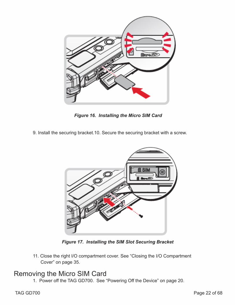
9. Install the securing bracket.10. Secure the securing bracket with a screw.
11. Close the right I/O compartment cover. See “Closing the I/O Compartment Cover” on page 35.
Removing the Micro SIM Card1. Power off the TAG GD700. See “Powering Off the Device” on page 20.
Figure 16. Installing the Micro SIM Card
TAG GD700 Page 22 of 68
Figure 17. Installing the SIM Slot Securing Bracket

2. Open the left I/O compartment cover. See “Opening the I/O Compartment Cover” on page 35.3. Locate the micro SIM slot in the left I/O parts.
4. Remove the screw securing the SIM slot securing bracket. 5. Remove the securing bracket.
Figure 18. Right View: Locating the Micro SIM Slot
Figure 19. Removing the SIM Slot Securing Bracket
TAG GD700 Page 23 of 68

6. Press the micro SIM card in and release it. The card springs out.7. Grasp the micro SIM card and remove it from the slot.
8. Install the securing bracket.9. Secure the securing bracket with a screw.
10. Close the right I/O compartment cover. See “Closing the I/O Compartment Cover” on page 36.
Figure 20. Removing the Micro SIM Card
Figure 21. Installing the SIM Slot Securing Bracket
TAG GD700 Page 24 of 68
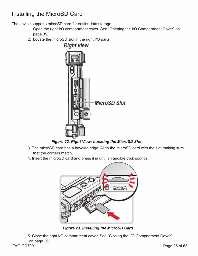
Installing the MicroSD CardThe device supports microSD card for easier data storage.
1. Open the right I/O compartment cover. See “Opening the I/O Compartment Cover” on page 35.2. Locate the microSD slot in the right I/O parts.
3. The microSD card has a beveled edge. Align the microSD card with the slot making sure that the corners match.4. Insert the microSD card and press it in until an audible click sounds.
5. Close the right I/O compartment cover. See “Closing the I/O Compartment Cover” on page 36.
Figure 22. Right View: Locating the MicroSD Slot
Figure 23. Installing the MicroSD Card
TAG GD700 Page 25 of 68

Removing the MicroSD Card
1. Open the right I/O compartment cover. See “Opening the I/O Compartment Cover” on page 35.2. Locate the microSD slot in the right I/O parts.
3. Press the microSD card in and release it. The card springs out.4. Grasp the microSD card and remove it from the slot.
5. Close the right I/O compartment cover. See “Closing the I/O Compartment Cover” on page 36.
Figure 24. Right View: Locating the MicroSD Slot
Figure 25. Removing the MicroSD Card
TAG GD700 Page 26 of 68

Installing on the Vehicle Dock
1. Power off the TAG GD700. See “Powering Off the Device” on page 20.2. Flip the levers upward on the both sides.
3. Align the docking connector on the TAG GD700 with the connector on the vehicle dock and push downward.4. Push the TAG GD700 forward and make sure it fixed with latches.
5. Press down the levers at the same time to lock.
Figure 26. Releasing the Levers
Figure 27. Installing the TAG GD700
TAG GD700 Page 27 of 68
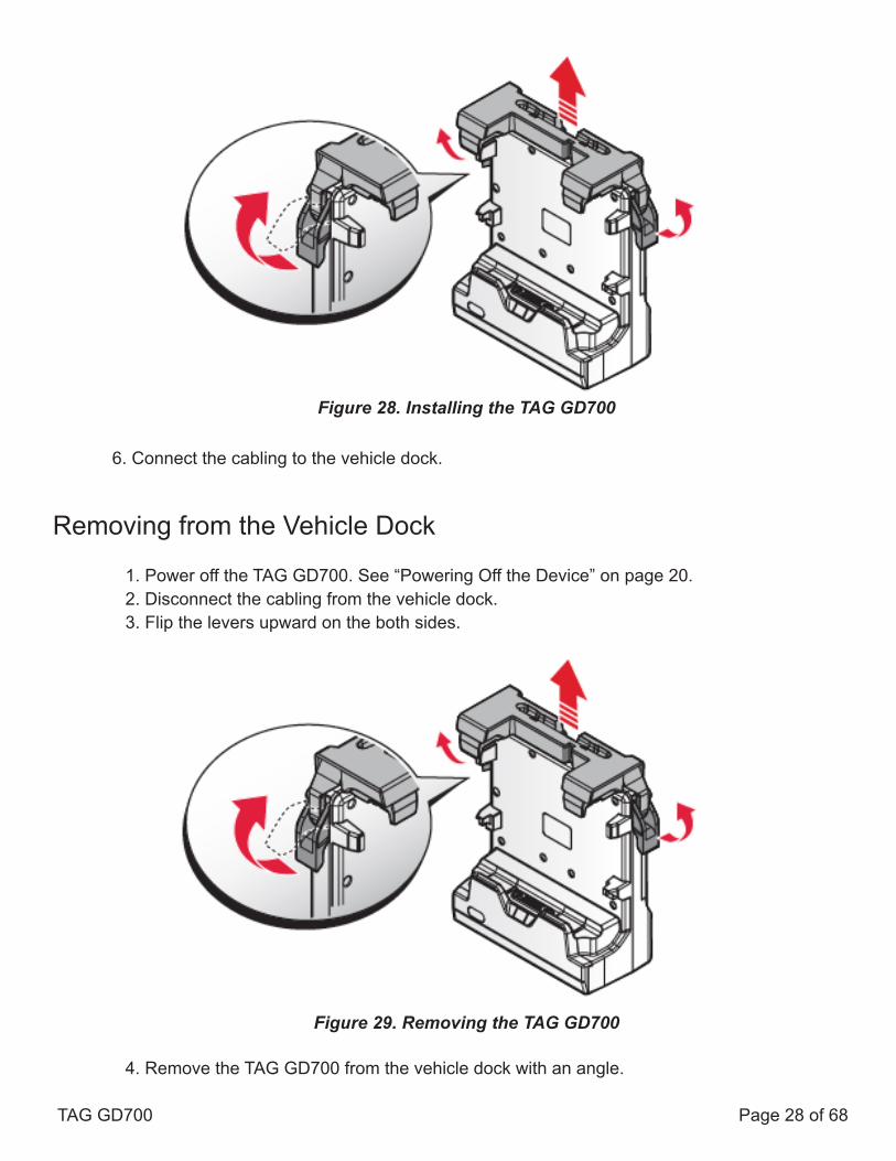
6. Connect the cabling to the vehicle dock.
Removing from the Vehicle Dock
1. Power off the TAG GD700. See “Powering Off the Device” on page 20.2. Disconnect the cabling from the vehicle dock.3. Flip the levers upward on the both sides.
4. Remove the TAG GD700 from the vehicle dock with an angle.
Figure 28. Installing the TAG GD700
Figure 29. Removing the TAG GD700
TAG GD700 Page 28 of 68

Installing on the Desktop Dock
1. Power off the TAG GD700. See “Powering Off the Device” on page 20.2. Align the docking connector on the TAG GD700 with the connector on the desktop dock and push downward.3. Push the TAG GD700 downward.
4. Connect the cabling to the desktop dock.
Figure 30. Removing the TAG GD700
Figure 31. Installing the TAG GD700
TAG GD700 Page 29 of 68

Removing from the Desktop Dock
1. Power off the TAG GD700. See “Powering Off the Device” on page 20.2. Disconnect the cabling from the desktop dock.3. Remove the TAG GD700 from the desktop dock.
Using the Stylus
Following the information below when using a stylus:
■ Use only the included stylus to touch the screen. Do not place any objects on its surface and do not press down strongly with sharp-pointed or hard objects that may leave marks (e.g., nails, pencils and ball point pens).■ Use the stylus only for touching the screen. Using it for any other purpose may damage the stylus and result in scratches on the screen.■ The pointer cannot follow the stylus movement if you move the stylus too quickly.
To make a selection, tap the screen once with the stylus. To double-click, tap twice withoutpausing. To do a long click, tap the screen and hold it for a few seconds.
Figure 32. Removing the TAG GD700
TAG GD700 Page 30 of 68

Removing the Protective Film from the Display
The front display of the TAG GD700 is protected during transport by a transparent film. This film should remain on the front display during assembly to avoid damage to the front display surface.Only remove the film once all of the assembly work has been completed.
Figure 33. Removing the Protective Film
TAG GD700 Page 31 of 68

Chapter 3. OperationRemoving the Snap-on Module Connector CoverThe snap-on module connector is located on the top side of the device. For further information see“Overview” on page 2
1. Locate the snap-on module connector cover.
2. Place the device display side down on a clean work surface.3. Remove the screws securing the cover.
Figure 34. Front View: Locating the Snap-on Module Connector Cover
Figure 35. Removing the Screws TAG GD700 Page 32 of 68

4. Removing the cover.
Replacing the Snap-on Module Connector Cover
The snap-on module connector is located on the top side of the device. For further information see“Overview” on page 2.
1. Locate the snap-on module connector cover.
Figure 36. Removing the Snap-on Module Connector Cover
Figure 37. Front View: Locating the Snap-on Module Connector Cover
TAG GD700 Page 33 of 68
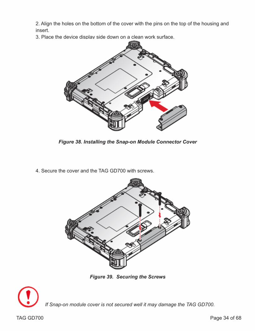
2. Align the holes on the bottom of the cover with the pins on the top of the housing and insert.3. Place the device display side down on a clean work surface.
4. Secure the cover and the TAG GD700 with screws.
If Snap-on module cover is not secured well it may damage the TAG GD700.
Figure 39. Securing the Screws
Figure 38. Installing the Snap-on Module Connector Cover
TAG GD700 Page 34 of 68

Opening the I/O Compartment Cover
1. Place the device display side down on a clean work surface.2. Locate the I/O compartment cover.
3. Pull out the I/O compartment cover.
Figure 40. Side View: Locating the I/O Compartment Cover
Figure 41. Opening the I/O Compartment Cover
TAG GD700 Page 35 of 68

Closing the I/O Compartment Cover
1. Place the device display side down on a clean work surface.2. Locate the I/O compartment cover.
3. Flip the I/O compartment cover and install.
The I/O compartment cover must be inserted correctly to prevent internal damage to the device.
Figure 42. Side View: Locating the I/O Compartment Cover
Figure 43. Closing the I/O Compartment Cover
TAG GD700 Page 36 of 68

Connecting to External CablingTo prevent damage to the device, connect all cabling and accessories beforepowering up the device.
Connect USB CablingThe TAG GD700 has two USB ports for connecting USB devices, such as a digital camera, scanner,printer, modem, and mouse. The USB port supports USB 2.0 or USB 3.0 devices.
1. Open the left or right I/O compartment cover. See “Opening the I/O Compartment Cover” on page 35.2. Connect to USB device via USB cable.
Connect Ethernet CablingThe TAG GD700 has an Ethernet port for connecting Ethernet.
A shielded cable is required to maintain emissions and susceptibility compliance.
1. Open the left I/O compartment cover. See “Opening the I/O Compartment Cover” on page 35.2. Connect LAN cable to Ethernet port on the TAG GD700.
Figure 45. Connect Ethernet Cabling
Figure 44. Connect USB Cabling
TAG GD700 Page 37 of 68

Connect Audio CablingFor higher audio quality, you can send sound through external audio devices such as speakers,headphones, or earphone using audio connector.
1. Open the right I/O compartment cover. See “Opening the I/O Compartment Cover” on page 35.2. Connect the audio cable.
Connect RS-232 CablingConnect to RS-232 devices with an RS-232 cable.
1. Open the left I/O compartment cover. See “Opening the I/O Compartment Cover” on page 35.2. Align the RS-232 cable with the port in the device and connect it.3. Turn the locking screws on the cable to secure it to the device.
Figure 46. Connect Audio Cabling
Figure 47. Connect RS-232 Cabling
TAG GD700 Page 38 of 68

Handstrap, Carrying Handle and Shoulder StrapThe TAG GD700 is equipped with a handstrap, a carrying handle and a shoulder strap for conve-nience and choice. Select the accessory that is right for your needs.
The handstrap can be installed with either the shoulder strap or the carrying handle. However, the handle and shoulder strap can not be installed together due to space constraints.
For more information, see “Connecting the Handstrap” on page 38, “Connecting the Carrying Handle” on page 39 and “Connecting the Shoulder Strap” on page 42.
Connecting the HandstrapThe handstrap makes it easy to carry the device with a single hand.
When attached, the handstrap blocks access to the extended battery and connector. To install the extended battery, you will need to remove the handstrap if it is previously installed.
1. Position the handstrap so that the inner strap is facing the device.2. Place the D-rings over the upper and lower positions on the device.3. Twist the D-rings (clockwise) to secure the handstrap.
Figure 48. Securing the Handstrap
TAG GD700 Page 39 of 68

Removing the Handstrap
1. Unscrew the D-rings securing the handstrap to the device.2. Remove the handstrap from the TAG GD700.
Connecting the Carrying Handle
1. The handle must face the correct way. The securing post and velcro should be facing outward.2. Thread one end of the strap through the metal loop on the bumper.
Figure 49. Removing the Handstrap
Figure 50. Inserting the Carrying Handle Through the Loop
TAG GD700 Page 40 of 68

3. Pull the strap end through the loop and insert the post through the slit on the strap.4. Secure the strap by attaching the two velcro ends together.
5. Repeat for the remaining strap end.Removing the Carrying Handle
1. Remove the strap from the velcro and securing post.
2. Pull the strap through the metal loop on the bumper.
3. Repeat from the remaining strap end.4. Remove the carrying handle.
Figure 51. Securing the Strap
Figure 52. Removing the Strap
Figure 53. Removing the Carrying Handle
TAG GD700 Page 41 of 68

Connecting the Shoulder Strap
1. The shoulder strap must face the correct way. The securing post and velcro should be facing outward.2. Thread one end of the strap through the metal loop on the bumper.
3. Pull the strap end through the loop and insert the post through the slit on the strap.4. Secure the strap by attaching the two velcro ends together.
5. Repeat for the remaining strap end.
Figure 54. Inserting the Shoulder Strap Through the Loop
Figure. 55. Securing the Strap
TAG GD700 Page 42 of 68

Removing the Shoulder Strap
1.Remove the strap from the velcro and securing post..
2. Pull the strap through the metal loop on the bumper.
3. Repeat for the remaining strap end.4. Remove the shoulder strap.
Figure 56. Removing the Strap
Figure 57. Removing the Shoulder Strap
TAG GD700 Page 43 of 68
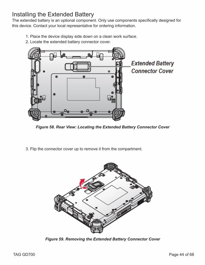
Installing the Extended BatteryThe extended battery is an optional component. Only use components specifically designed forthis device. Contact your local representative for ordering information.
1. Place the device display side down on a clean work surface.2. Locate the extended battery connector cover.
3. Flip the connector cover up to remove it from the compartment.
Figure 58. Rear View: Locating the Extended Battery Connector Cover
Figure 59. Removing the Extended Battery Connector Cover
TAG GD700 Page 44 of 68

4. Align the tabs on the extended battery bracket with the slots on the rear side of the TAG GD700.
5. Push the extended battery bracket toward to lock.
6. Securing the extended battery bracket and the TAG GD700 with screws.
Figure 60. Aligning the Extended Battery Bracket
Figure 61. Installing the Extended Battery Bracket
Figure 62. Securing the Screws
TAG GD700 Page 45 of 68

7. Install the connector cover in the cover placeholder.
8. Align the tabs on the extended battery with the slots on the extended battery bracket.9. Angle the battery in place and set the tabs in the bracket slots.10. Lower the raised end of the extended battery and press in place until an audible click is heard.
11. Press the locking switch on the top-left side to lock the extended battery.
Figure 63. Placing the Extended Battery Connector Cover in the Cover Placeholder
Figure 64. Installing the Extended Battery
Figure 65. Locking the Extended Battery
TAG GD700 Page 46 of 68

Removing the Extended Battery
1. Press the locking switch on the top-left side to the unlock position.
2. Press and hold the release button as shown in the image to release the battery.3. Hold the battery and angle the top side up to remove.
Figure 66. Unlock the Extended Battery
Figure 67. Removing the Extended Battery
TAG GD700 Page 47 of 68
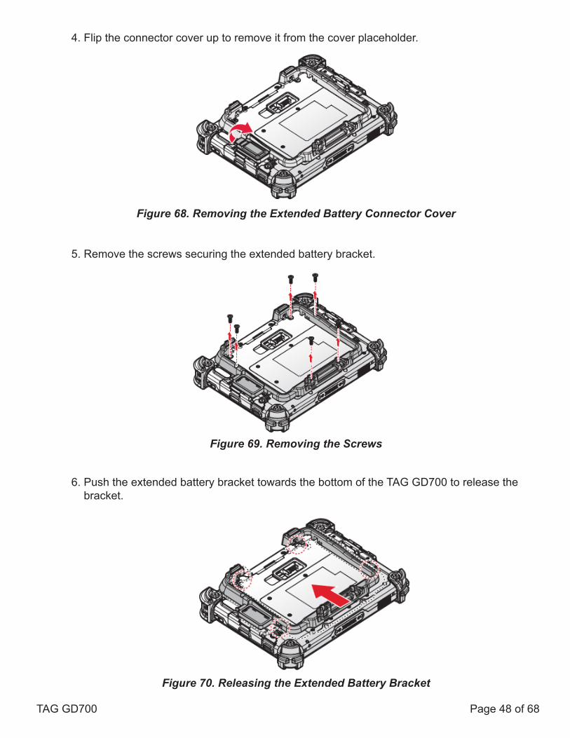
4. Flip the connector cover up to remove it from the cover placeholder.
5. Remove the screws securing the extended battery bracket.
6. Push the extended battery bracket towards the bottom of the TAG GD700 to release the bracket.
Figure 68. Removing the Extended Battery Connector Cover
Figure 69. Removing the Screws
Figure 70. Releasing the Extended Battery Bracket
TAG GD700 Page 48 of 68
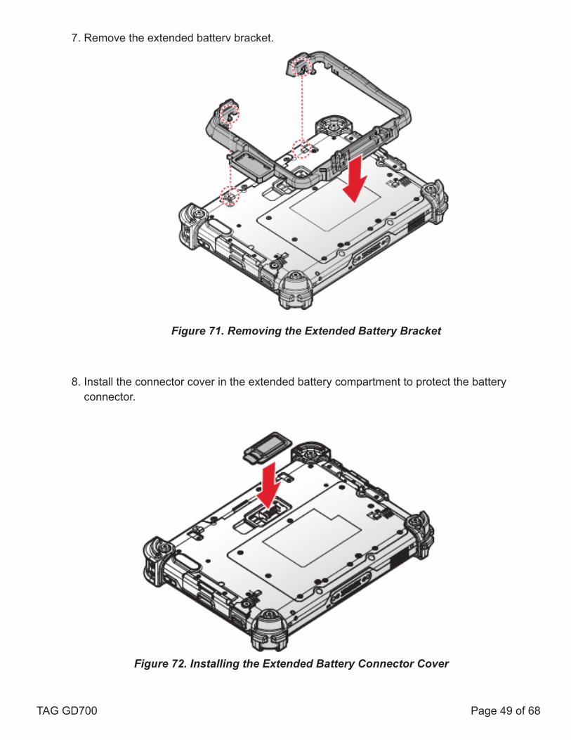
7. Remove the extended battery bracket.
8. Install the connector cover in the extended battery compartment to protect the battery connector.
Figure 71. Removing the Extended Battery Bracket
Figure 72. Installing the Extended Battery Connector Cover
TAG GD700 Page 49 of 68
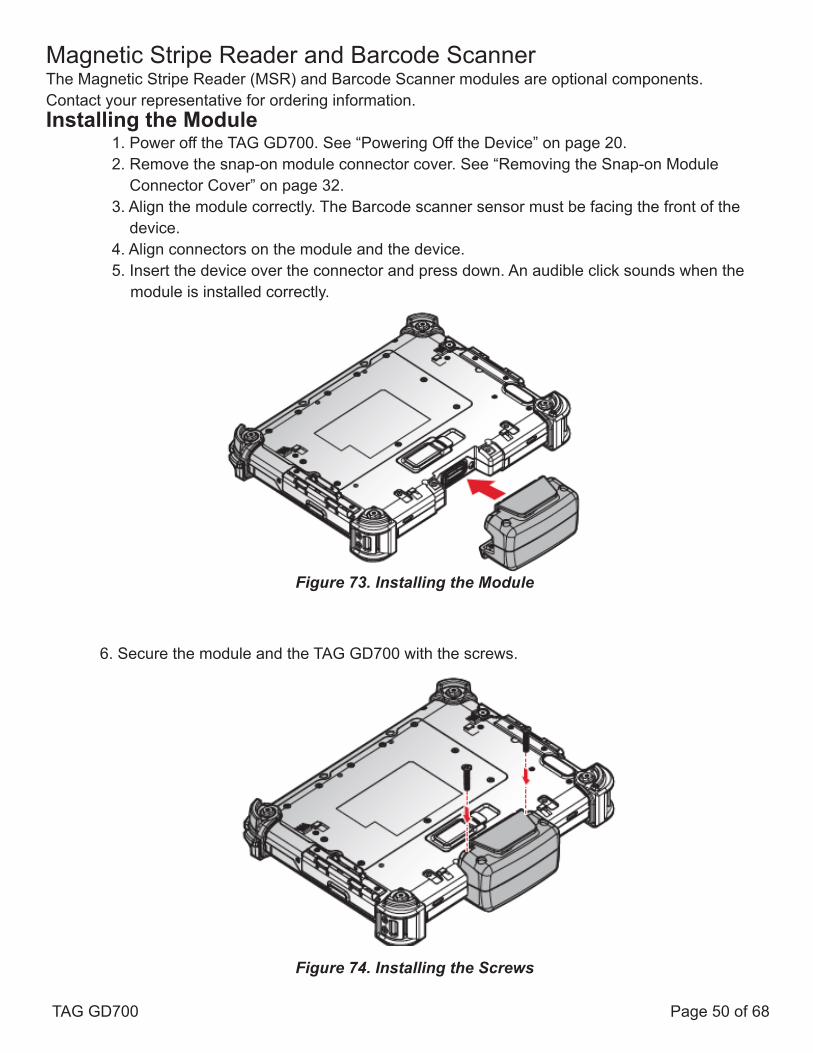
Magnetic Stripe Reader and Barcode ScannerThe Magnetic Stripe Reader (MSR) and Barcode Scanner modules are optional components.Contact your representative for ordering information.Installing the Module
1. Power off the TAG GD700. See “Powering Off the Device” on page 20.2. Remove the snap-on module connector cover. See “Removing the Snap-on Module Connector Cover” on page 32.3. Align the module correctly. The Barcode scanner sensor must be facing the front of the device.4. Align connectors on the module and the device.5. Insert the device over the connector and press down. An audible click sounds when the
module is installed correctly.
6. Secure the module and the TAG GD700 with the screws.
Figure 74. Installing the Screws
Figure 73. Installing the Module
TAG GD700 Page 50 of 68

Removing the Module
1. Power off the TAG GD700. See “Powering Off the Device” on page 20.2. Remove the screws securing the module.
3. Grasp the module from both sides and gently pull the module off.4. Remove the module.
5. Replace the snap-on module connector cover. See “Replacing the Snap-on Module Connector Cover” on page 33.
Figure 76. Removing the Module
Figure 75. Removing the Screws
TAG GD700 Page 51 of 68

Magnetic Stripe Reader and Machine-Readable Zone ReaderThe Magnetic Stripe Reader (MSR) and Machine-Readable Zone Reader modules are optionalcomponents. Contact your representative for ordering information.
Installing the Module
1. Power off the TAG GD700. See “Powering Off the Device” on page 20.2. Remove the snap-on module connector cover. See “Removing the Snap-on Module Connector Cover” on page 32.3. Align the module correctly. The reader sensor must be facing the front of the device.4. Align connectors on the module and the device.5. Insert the device over the connector and press down. An audible click sounds when the module is installed correctly.
6. Secure the module and the TAG GD700 with the screws.
Figure 78. Installing the Screws
Figure 77. Installing the Module
TAG GD700 Page 52 of 68

Removing the Module1. Power off the TAG GD700. See “Powering Off the Device” on page 20.2. Remove the screws securing the module.
3. Grasp the module from both sides and gently pull the module off.4. Remove the module.
5. Replace the snap-on module connector cover. See “Replacing the Snap-on ModuleConnector Cover” on page 32.
Connecting to a Wireless NetworkBefore you can make use of the TAG GD700 wireless functions, you need to connect to a network.The following is a set of procedures for connecting to a wireless network.
1. Before beginning, make sure your Wi-Fi setting is enabled and you are within range of a wireless network. If your Wi-Fi setting is disabled, proceed to step 2.
■ Find the network icon located on the right side of the taskbar. If the icon displays an X in a red circle, you are not within range of a wireless network. Move to a different spot until the Wi-Fi icon changes status indicating availability to a wireless network.
2. From any screen, open the Menu by sliding your finger inward from the screen’s right edge. The Menu displays along the screen’s right side.3. In the Menu, tap Settings to open the Settings menu.
Figure 80. Removing the Module
Figure 79. Removing the Screws
TAG GD700 Page 53 of 68

4. In Settings, tap the Network icon to display the Networks connection settings.5. The Wi-Fi menu displays. By default, the Wi-Fi menu is set to Off. Tap the bar next to Off to toggle Wi-Fi to On. This enables the Wi-Fi option.6. Once Wi-Fi is enabled a listing of all available wireless networks displays. The wireless networks with the strongest signal are atop the list.7. Select the network you want to connect, and tap the Connect button. You can tap the Connect Automatically check box if you connect to this network frequently. If you connect to the network, you are finished with the process. The network is considered an Open unsecured network, no password is required.8. If a password is required, type the password in the Enter the network security key field. Alternatively, you can also push the WPS button on your router to begin the security handshake.9. Tap Next to finish the connection process.**You have successfully connected to a wireless network.
Pairing the NFC DeviceThe NFC function allows the transfer of information between two NFC-equipped devices. Beforebeginning the procedure make sure your smart device has the NFC function enabled.To enable and use the NFC function:
1. Tap APPS > Setting > More....2. Tap NFC to turn the NFC function on.3. Use your NFC-enabled device to touch to the TAG GD700.
Once the two devices are paired, information sharing is available through the NFC connection.
Figure 81. Pairing the NFC Device
TAG GD700 Page 54 of 68

Chapter 4. Using BIOS Setup UtilityYour ruggedized tablet has a BIOS setup utility which allows you to configure important system set-tings, including settings for the Boot and AP menus as well as the device’s basic settings--the system reads the basic settings during initialization in order to boot correctly
When to Use the BIOS Setup UtilityYou need to run the BIOS Setup utility when:■ Restoring to BIOS settings to factory default■ Modifying specific hardware settings■ Modifying specific settings to optimize system performance■ Installing Windows™ 10 Operating System
Accessing the BIOS Setup Utility
The BIOS Setup Utility screens shown in this chapter are for your reference only. The actual images or settings on your tablet computer may differ.The BIOS Setup Utility program may have been updated after the publication of this manual.
To run the BIOS Setup Utility, use the following procedures:1. Connect a keyboard to the TAG GD700.2. When the TAG GD700 is powered off, press the Power button to start up the device. The
power LED lights. Press F5 on the keyboard or Home key on the TAG GD700 until the BIOS Post screen displays.
The BIOS POST screen appears as shown.
3 From the BIOS POST screen select App Menu to open the BIOS Setup Utility.
Figure 82. BIOS POST Screen TAG GD700 Page 55 of 68

Due to the device’s fast boot up and boot down time, there is only a small time frame of a few seconds between the release of the Power button and the opportunity to press the Windows™ Home key.
The App Menu displays.
Installing an Operating System
Setting Up a Windows™ 10 Installation Environment
There are several settings in BIOS that must be modified before you can install a Windows™ 10 Operating System.
Use the following guidelines to prepare the BIOS environment:
■ Step 1: Enable CSM Support1. Access the BIOS Setup Utility, see “Accessing the BIOS Setup Utility” on page 55.2. Navigate to APP Menu > Main > Boot Features.3. Locate the CSM Support setting and tap the drop-down menu to display the options.4. Tap Yes to enable CSM support.
Figure 83. BIOS Setup Utility: App Menu Screen
TAG GD700 Page 56 of 68
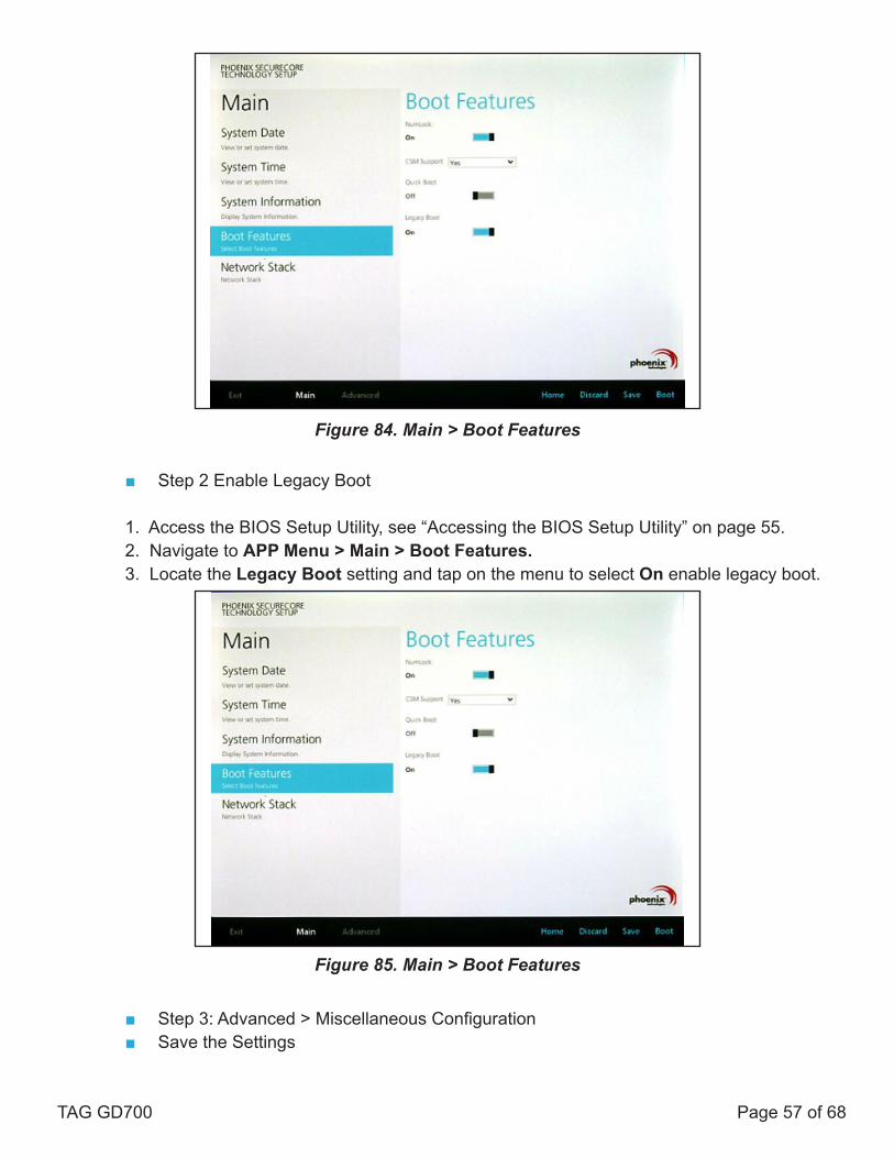
■ Step 2 Enable Legacy Boot
1. Access the BIOS Setup Utility, see “Accessing the BIOS Setup Utility” on page 55.2. Navigate to APP Menu > Main > Boot Features.3. Locate the Legacy Boot setting and tap on the menu to select On enable legacy boot.
■ Step 3: Advanced > Miscellaneous Configuration■ Save the Settings
Figure 84. Main > Boot Features
Figure 85. Main > Boot Features
TAG GD700 Page 57 of 68

After you configure BIOS, you will need to save the settings.
1. Navigate to APP Menu > Exit and tap Exit Saving Changes.
2. A prompt display, tap Yes to save the configuration.
The BIOS settings are configured and the Windows™ 10 Operating System can be installed.
BIOS Passwords
Setting Up a Supervisor PasswordTo setup a supervisor password, follow the procedure as described:
1. Go to APP Menu > Security > Account’s Password Status.2. Tap the Enter icon next to Setup the Supervisor Password to access the virtual keyboard.
Figure 86. Exit the BIOS Utility
Figure 87. Security > Account’s Password Status TAG GD700 Page 58 of 68

3. Tap the password to use for the Supervisor profile and tap Enter.
4. Verification of the password is required. Tap the same password again and tap Enter to confirm the new password.5. Navigate to APP Menu > Exit.
6. Tap Exit Saving Changes to display the confirmation screen.7. Tap Yes to save the new configuration settings.
After setting the Supervisor password, the password is required to access the BIOS Setup Utility.
Figure 88. Set Supervisor Password
Figure 89. Exit Screen
TAG GD700 Page 59 of 68

Changing a Supervisor Password
1. Navigate to APP Menu > Security > Account’s Password Status.2. Tap the Enter icon next to Setup Supervisor Password.3. Enter the current supervisor password.4. Enter a new password.5. Enter the new password again to confirm.6. Go to APP Menu > Exit.7. Tap Exit Saving Changes and tap Yes to save the configuration.
Resetting a Supervisor Password
A supervisor password can not be reset. In the event that you forget the supervisory password, you will need to reflash the BIOS to enter the BIOS menus. Refer to “Updating BIOS” on page 60 to reflash the BIOS.
EC and BIOS
Updating BIOSThis procedure allows you to update and reflash the system BIOS. Both procedures follow the same steps as described in the following.
Make sure to protect your device from power loss during the BIOS update procedure to prevent irreparable damage to your system’s main-board.
For this procedure, it is highly recommended to connect the device to the AC adapter to prevent a sudden loss of power during the BIOS updating process.
1. Contact your technical sales or technical representative to obtain the correct BIOS file.2. Copy the BIOS file on to the USB device.3. Connect the USB device to one of the device’s USB ports and power on the TAG GD700.
A USB keyboard is required for entering command.
4. Once the device is on and the Windows™ 10 Home screen displays, open the Menu bar by sliding your finger inward from the screen’s right edge. The Menu displays.
TAG GD700 Page 60 of 68
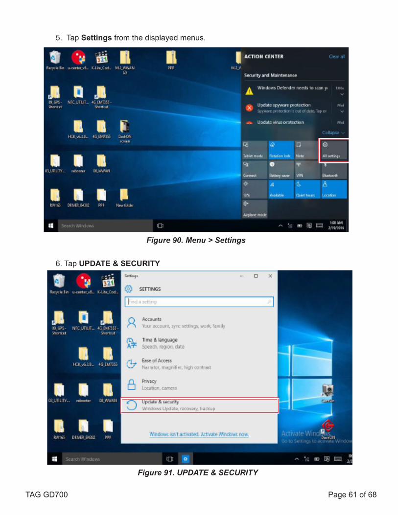
5. Tap Settings from the displayed menus.
6. Tap UPDATE & SECURITY
Figure 90. Menu > Settings
Figure 91. UPDATE & SECURITY
TAG GD700 Page 61 of 68

7. From the UPDATE & SECURITY menu, tap Recovery to continue.
8. From the RECOVERY screen, tap Restart now.
Figure 92. Recovery
Figure 93. Restart Now
TAG GD700 Page 62 of 68

9. Tap Use a device to select a boot up preference.
10. From the Use a device menu, tap Internal Shell to open the command screen. Make sure connect the TAG GD700 to the AC adapter to prevent a sudden loss of power.
Figure 94. Use a Device
Figure 95. Internal Shell TAG GD700 Page 63 of 68

11. In the command screen, enter fs1: to select the USB device already connected to the device. The command directs you to the USB device’s root menu.
12. If the BIOS file is in a folder and not in the root directory, navigate to the target folder.13. Type wf (.nsh) and tap Enter. wf is the designated BIOS file. **Do not turn off your device or interfere with the reflash process until the process is complete. 14. Once the process is complete, the TAG GD700 automatically reboots. The BIOS is now updated. **The BIOS is now updated.
Updating EC
Connect the TAG GD700 to the AC adapter to prevent a sudden loss of power.
1. Updating EC requires the use of the Internal Shell Command menu, refer to steps 1 to 12 of “Updating BIOS”.2. Enter the EC source file folder.3. In the source folder, enter “f”.4. Do not turn off your device or interfere with the reflash process until the process is complete. **The system reboots once the process is completed.
Figure 96. Internal Shell Command Screen
TAG GD700 Page 64 of 68

Chapter 5. Using the DashON UtilityOverview
The DashON resident program is designed to provide near-instant access to your device’s settings and configuration within a single, easy to use interface.
The following information illustrates and describes the various settings available for configuration through the DashON menus.
Important: Do not terminate or remove the DashON program manually or the ambient light sensor and the function buttons will malfunction.
Download the latest information and documentation through the TAG Global Systems official site: www.TAGGlobalSystems.com
Table 7 . DashON Overview
Function Description
EXIT Minimize DashON and return to the desktop.
Button Lock Lock or unlock all the physical buttons except Power button.
Screen Auto Rotate Disable or enable screen auto rotate function.
Airplane Turn on or off the airplane mode.
Battery Shows the battery level or charging status.
Brightness Adjust brightness level and enable or disable auto brightness function.Volume Control Adjust volume level and enable or disable mute function.GNSS Disable or enable GNSS function.
Wi-Fi Disable or enable Wi-Fi function.
Bluetooth® Disable or enable Bluetooth® function.Touch Screen Lock Lock or unlock the touch screen.
ECO Mode Disable or enable ECO mode to save battery life when using the device.
Power Plan Manage how your tablet uses power.
Info Viewer View system specifications. The menu is for display only.
Display Switch Choose a display mode when connect to another output device.
Button Setting Predefined functions settings. Supports function button customizing.
Camera Use the rear camera to take photos and videos
TAG GD700 Page 65 of 68

Chapter 6. TroubleshootingUse the troubleshooting tables in this section to fix problems with the Wi-Fi connection, 802.1x security, or general problems with operating the computer.
If you send the computer in for service, it is your responsibility to save the computer data and configuration. TAG Global Systems is responsible only for ensuring that the hardware matches the original configuration when repairing or replacing the computer.
Troubleshoot the Wi-Fi Connection
Use this troubleshooting table to help solve problems with your 802.11 radio connection.
Q. When you turn on the computer after it was suspended for a while (10 to 15 minutes or longer), it can no longer send or receive messages over the network.
A. Host may have deactivated or lost current terminal emulation session. In a TCP/IP direct connect network, turn off the “Keep Alive” message from host to maintain the TCP session while the computer is suspended.
Q. The computer is connected to the network and you move to a new site to collect data. Your computer now shows you are not connected to the network.
A. Move closer to an access point or to a different location to reestablish communications until you reconnect with the network.
Q. The computer appears to be connected to the network, but you cannot establish a terminal emulation session with the host computer.
A. There may be a problem with the host computer, or with the connection between the access point and the host computer. Check with the network administrator to make sure the host is running and allowing users to log in to the system.
Q. The computer appears to be connected to the network, but the host computer is not receiving any information from the computer.
A. There may be a problem with the connection between the access point and the host computer. Check with the network administrator or use your access point user’s manual.
Q. A network connection icon appears in the toolbar, but then disappears.
A. The computer may not be communicating with the intended access point. Make sure the network name matches the access point network name. The access point may not be communicating with the server. Ensure the access point is turned on, properly configured, and has 802.1x security enabled.
TAG GD700 Page 66 of 68

Troubleshoot Operating the Computer Use this section to troubleshoot problems that may prevent you from being able to operate the computer.
Q. You press the Power button and nothing happens.
A. Make sure that power is connected to the computer.
Q. The computer appears to be locked up and you cannot enter data.
A. Restart the computer.
Call Product Support
Please contact the dealer who supplied this device, or contact your TAG Global Systems representative. Alternately, contact the manufacturer at www.TAGGlobalSystems.com.
To better assist you have the following information ready:■ Configuration number■ Serial number■ Operating system, BIOS, and MCU versions■ Service pack version■ System component versions■ If you are using security, know the type and the full set of parameters
TAG GD700 Page 67 of 68

Chapter 7. MaintenanceCleaning the Device
Danger of electric shock when cleaning or maintaining the TAG GD700.To avoid electric shock, turn the TAG GD700 off and disconnect it from the power supply before cleaning or maintaining it.
Housing■ The housing of the TAG GD700 is best cleaned with a damp cloth.■ Use of compressed air, a high-pressure cleaner or vacuum cleaner may damage the surface.■ Use of a high-pressure cleaner, the additional risk of water entering the TAG GD700 may damage the electronics or touch screen.
Touch Screen■ Use neutral detergent or isopropyl alcohol on a clean soft cloth to clean the panel surface.■ Prevent using any kind of chemical solvent, acidic or alkali solution.
Returning the Device
Please put the contents in the original package gently when you need to return the TAG GD700.
Contacting TAG Global Systems
If you experience technical difficulties, please consult your distributor or contact the technical services department: www.TAGGlobalSystems.com
TAG GD700 Page 68 of 68