Embed Size (px)
Citation preview
– 1 –
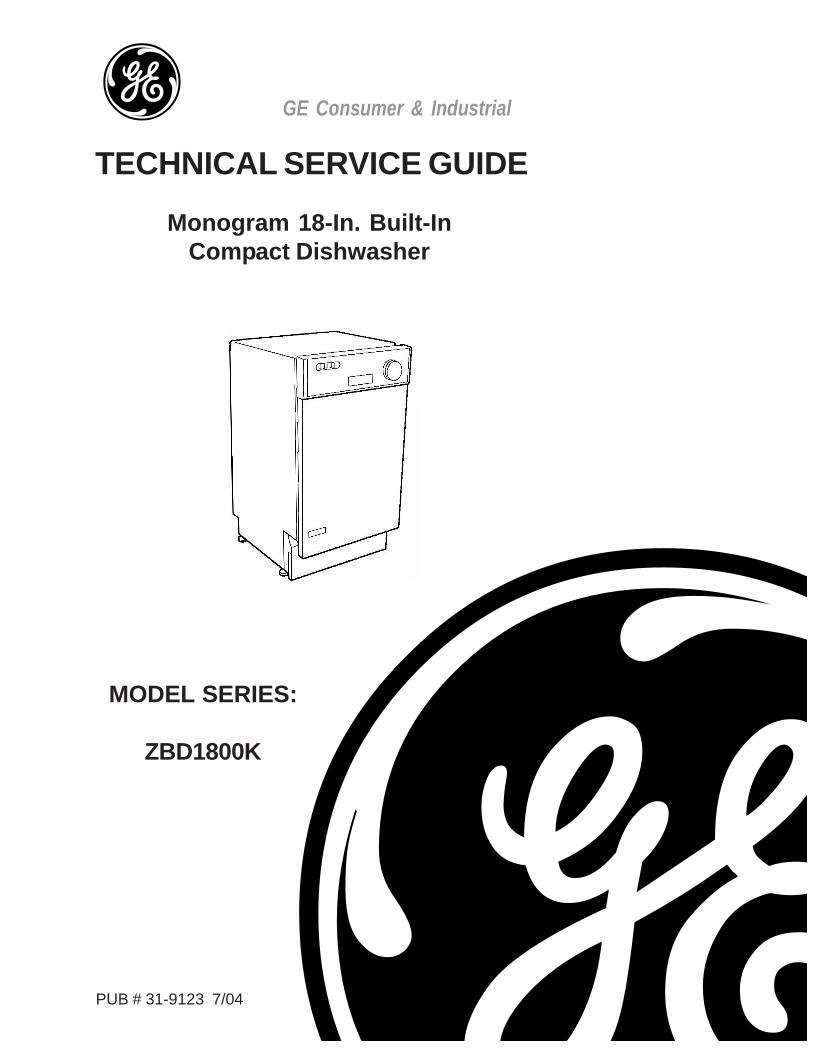
MODEL SERIES:
ZBD1800K
Monogram 18-In. Built-InCompact Dishwasher
GE Consumer & Industrial
TECHNICAL SERVICE GUIDE
PUB # 31-9123 7/04
– 2 –
IMPORTANT SAFETY NOTICEThe information in this service guide is intended for use by
individuals possessing adequate backgrounds of electrical,electronic, and mechanical experience. Any attempt to repair amajor appliance may result in personal injury and propertydamage. The manufacturer or seller cannot be responsible for theinterpretation of this information, nor can it assume any liability inconnection with its use.
WARNINGTo avoid personal injury, disconnect power before servicing this
product. If electrical power is required for diagnosis or testpurposes, disconnect the power immediately after performing thenecessary checks.
RECONNECT ALL GROUNDING DEVICESIf grounding wires, screws, straps, clips, nuts, or washers used
to complete a path to ground are removed for service, they mustbe returned to their original position and properly fastened.
GE Consumer & IndustrialTechnical Service Guide
Copyright © 2004
All rights reserved. This service guide may not be reproduced in whole or in part,`in any form, without written permission from the General Electric Company.
– 3 –
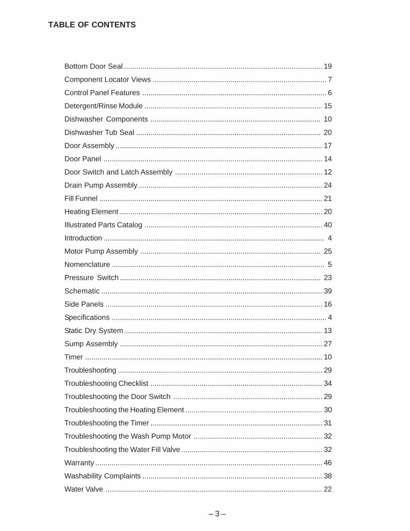
TABLE OF CONTENTS
Bottom Door Seal ................................................................................................. 19
Component Locator Views ..................................................................................... 7
Control Panel Features .......................................................................................... 6
Detergent/Rinse Module ....................................................................................... 15
Dishwasher Components ................................................................................... 10
Dishwasher Tub Seal .......................................................................................... 20
Door Assembly ..................................................................................................... 17
Door Panel ........................................................................................................... 14
Door Switch and Latch Assembly ........................................................................ 12
Drain Pump Assembly.......................................................................................... 24
Fill Funnel ............................................................................................................. 21
Heating Element ................................................................................................... 20
Illustrated Parts Catalog ....................................................................................... 40
Introduction ............................................................................................................ 4
Motor Pump Assembly ........................................................................................ 25
Nomenclature ........................................................................................................ 5
Pressure Switch .................................................................................................. 23
Schematic ............................................................................................................ 39
Side Panels .......................................................................................................... 16
Specifications ......................................................................................................... 4
Static Dry System................................................................................................. 13
Sump Assembly ................................................................................................... 27
Timer .................................................................................................................... 10
Troubleshooting .................................................................................................... 29
Troubleshooting Checklist .................................................................................... 34
Troubleshooting the Door Switch ......................................................................... 29
Troubleshooting the Heating Element ................................................................... 30
Troubleshooting the Timer .................................................................................... 31
Troubleshooting the Wash Pump Motor ............................................................... 32
Troubleshooting the Water Fill Valve ..................................................................... 32
Warranty ............................................................................................................... 46
Washability Complaints ........................................................................................ 38
Water Valve .......................................................................................................... 22
– 4 –
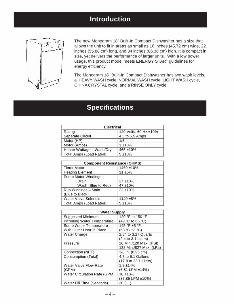
Introduction
The new Monogram 18" Built-In Compact Dishwasher has a size thatallows the unit to fit in areas as small as 18 inches (45.72 cm) wide, 22inches (55.88 cm) long, and 34 inches (86.36 cm) high. It is compact insize, yet delivers the performance of larger units. With a low powerusage, this product model meets ENERGY STAR® guidelines forenergy efficiency.
The Monogram 18" Built-In Compact Dishwasher has two wash levels,a HEAVY WASH cycle, NORMAL WASH cycle, LIGHT WASH cycle,CHINA CRYSTAL cycle, and a RINSE ONLY cycle.
Electrical Rating 120 Volts, 60 Hz ±10% Separate Circuit 4.5 to 5.5 Amps Motor (HP) 1/5 Motor (Amps) 1 ±10% Heater Wattage – Wash/Dry 465 ±10% Total Amps (Load Rated) 5 ±10%
Component Resistance (OHMS) Timer Motor 1460 ±10% Heating Element 31 ±5% Pump Motor Windings Drain Wash (Blue to Red)
27 ±10% 47 ±10%
Run Windings – Main (Blue to Black)
22 ±10%
Water Valve Solenoid 1140 ±5% Total Amps (Load Rated) 5 ±10%
Water Supply Suggested Minimum Incoming Water Temperature
120 °F to 150 °F (49 °C to 66 °C)
Sump Water Temperature With Outer Door In Place
145 °F ±5 °F (63 °C ±3 °C)
Water Charge 2.54 to 3.27 Quarts (2.4 to 3.1 Liters)
Pressure 20 Min./120 Max. (PSI) 138 Min./827 Max. (kPa)
Connection (NPT) 3/8 In. (0.95 cm) Consumption (Total) 4.7 to 6.1 Gallons
(17.8 to 23.1 Liters) Water Valve Flow Rate (GPM)
1.8 ±14% (6.81 LPM ±14%)
Water Circulation Rate (GPM) 10 ±10% (37.85 LPM ±10%)
Water Fill Time (Seconds) 30 (±1)
Specifications
– 5 –
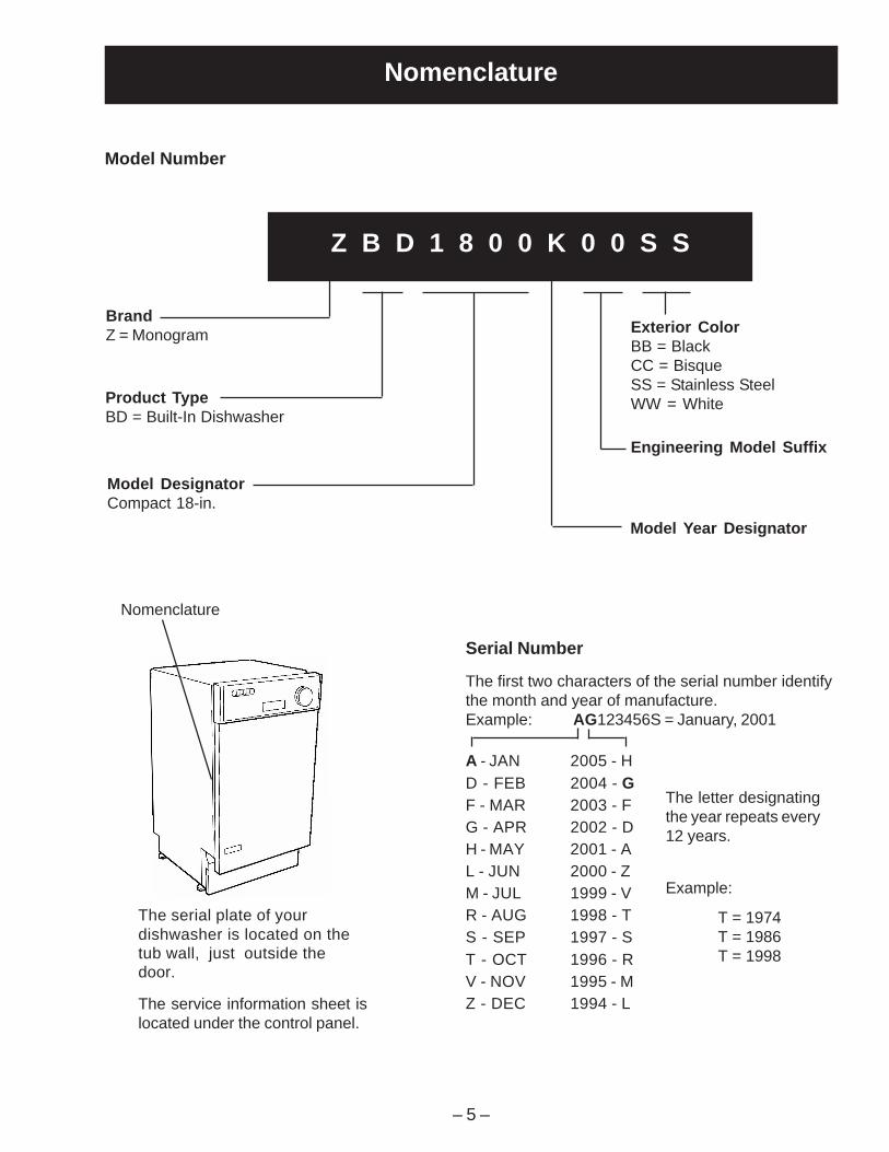
Model DesignatorCompact 18-in.
Nomenclature
The letter designatingthe year repeats every12 years.
Example:
T = 1974T = 1986T = 1998
Z B D 1 8 0 0 K 0 0 S S
BrandZ = Monogram
Product TypeBD = Built-In Dishwasher
Exterior ColorBB = BlackCC = BisqueSS = Stainless SteelWW = White
Model Year Designator
Engineering Model Suffix
Nomenclature
Model Number
The serial plate of yourdishwasher is located on thetub wall, just outside thedoor.
The service information sheet islocated under the control panel.
Serial Number
The first two characters of the serial number identifythe month and year of manufacture.Example: AG123456S = January, 2001
A - JAN 2005 - HD - FEB 2004 - GF - MAR 2003 - FG - APR 2002 - DH - MAY 2001 - AL - JUN 2000 - ZM - JUL 1999 - VR - AUG 1998 - TS - SEP 1997 - ST - OCT 1996 - RV - NOV 1995 - MZ - DEC 1994 - L
– 6 –
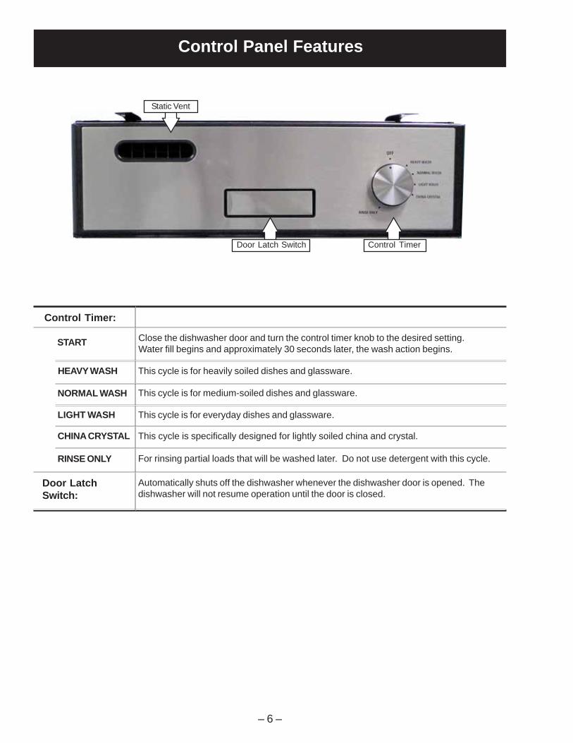
Control Panel Features
Control Timer:
HEAVY WASH
NORMAL WASH
LIGHT WASH
CHINA CRYSTAL
RINSE ONLY For rinsing partial loads that will be washed later. Do not use detergent with this cycle.
This cycle is for everyday dishes and glassware.
This cycle is specifically designed for lightly soiled china and crystal.
This cycle is for medium-soiled dishes and glassware.
This cycle is for heavily soiled dishes and glassware.
START Close the dishwasher door and turn the control timer knob to the desired setting.Water fill begins and approximately 30 seconds later, the wash action begins.
Door LatchSwitch:
Automatically shuts off the dishwasher whenever the dishwasher door is opened. Thedishwasher will not resume operation until the door is closed.
Door Latch Switch Control Timer
Static Vent

– 7 –
Door Latch Switch Control Timer
Front View
Component Locator Views
Control Panel View
Static Vent
Side Panel
Control Panel
Access Panel
Insulation
– 8 –
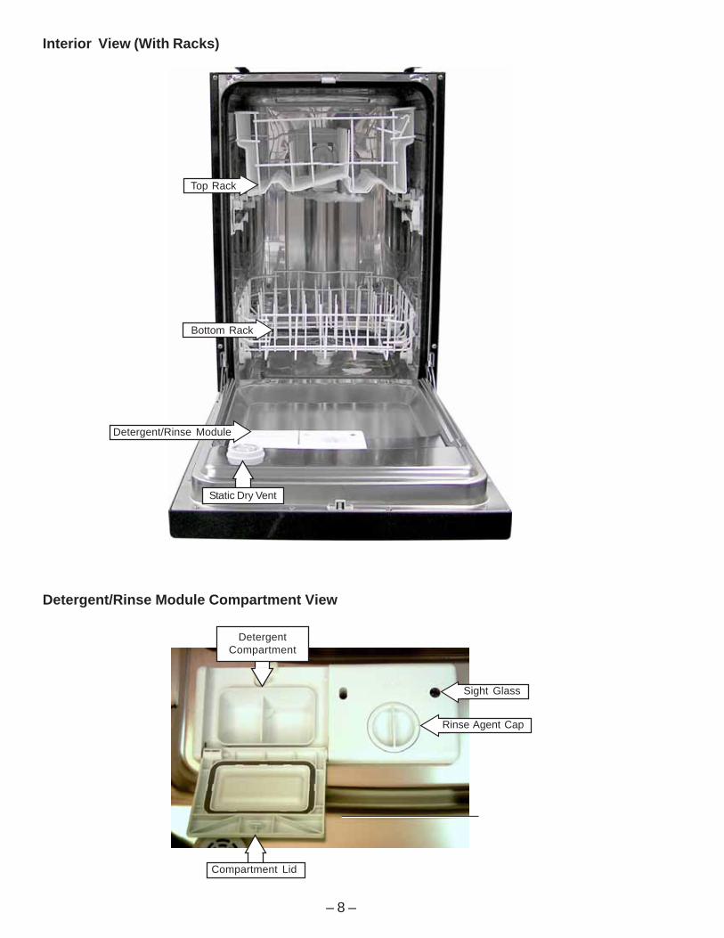
Interior View (With Racks)
Detergent/Rinse Module Compartment View
Compartment Lid
Sight Glass
Rinse Agent Cap
DetergentCompartment
Static Dry Vent
Top Rack
Bottom Rack
Detergent/Rinse Module

– 9 –
Interior View of Basin (With Racks Removed)
Bottom View (Looking Up)
Right Side View(Side Panel and Insulation Removed)
Filter Assembly
Microfilter
Clamp Nut
Heating Element
Spray Arm
Fill Funnel
PressureSwitch Hose
Fill Hose
Door Tension Spring
Sump
Drain Pump
CapacitorMotor PumpAssembly
– 10 –
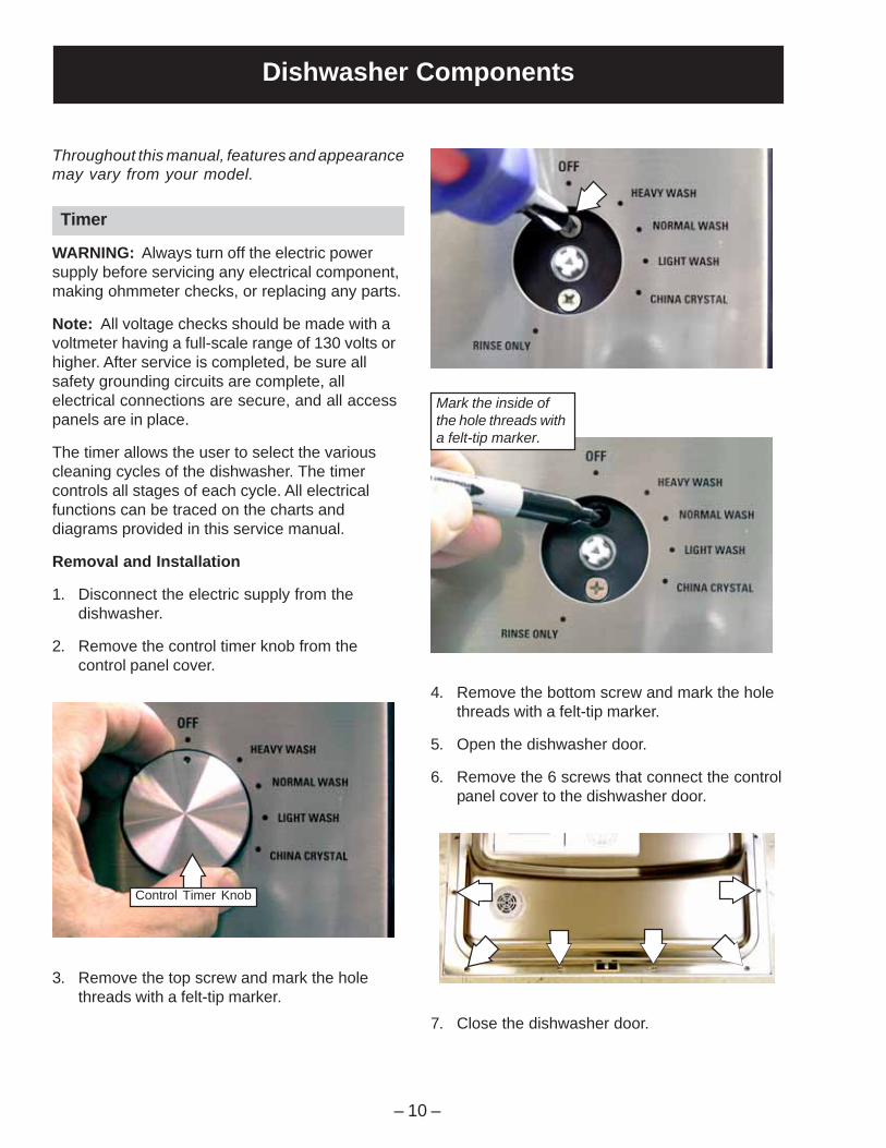
Dishwasher Components
Throughout this manual, features and appearancemay vary from your model.
3. Remove the top screw and mark the holethreads with a felt-tip marker.
4. Remove the bottom screw and mark the holethreads with a felt-tip marker.
5. Open the dishwasher door.
6. Remove the 6 screws that connect the controlpanel cover to the dishwasher door.
Mark the inside ofthe hole threads witha felt-tip marker.
7. Close the dishwasher door.
Timer
WARNING: Always turn off the electric powersupply before servicing any electrical component,making ohmmeter checks, or replacing any parts.
Note: All voltage checks should be made with avoltmeter having a full-scale range of 130 volts orhigher. After service is completed, be sure allsafety grounding circuits are complete, allelectrical connections are secure, and all accesspanels are in place.
The timer allows the user to select the variouscleaning cycles of the dishwasher. The timercontrols all stages of each cycle. All electricalfunctions can be traced on the charts anddiagrams provided in this service manual.
Removal and Installation
1. Disconnect the electric supply from thedishwasher.
2. Remove the control timer knob from thecontrol panel cover.
Control Timer Knob
– 11 –
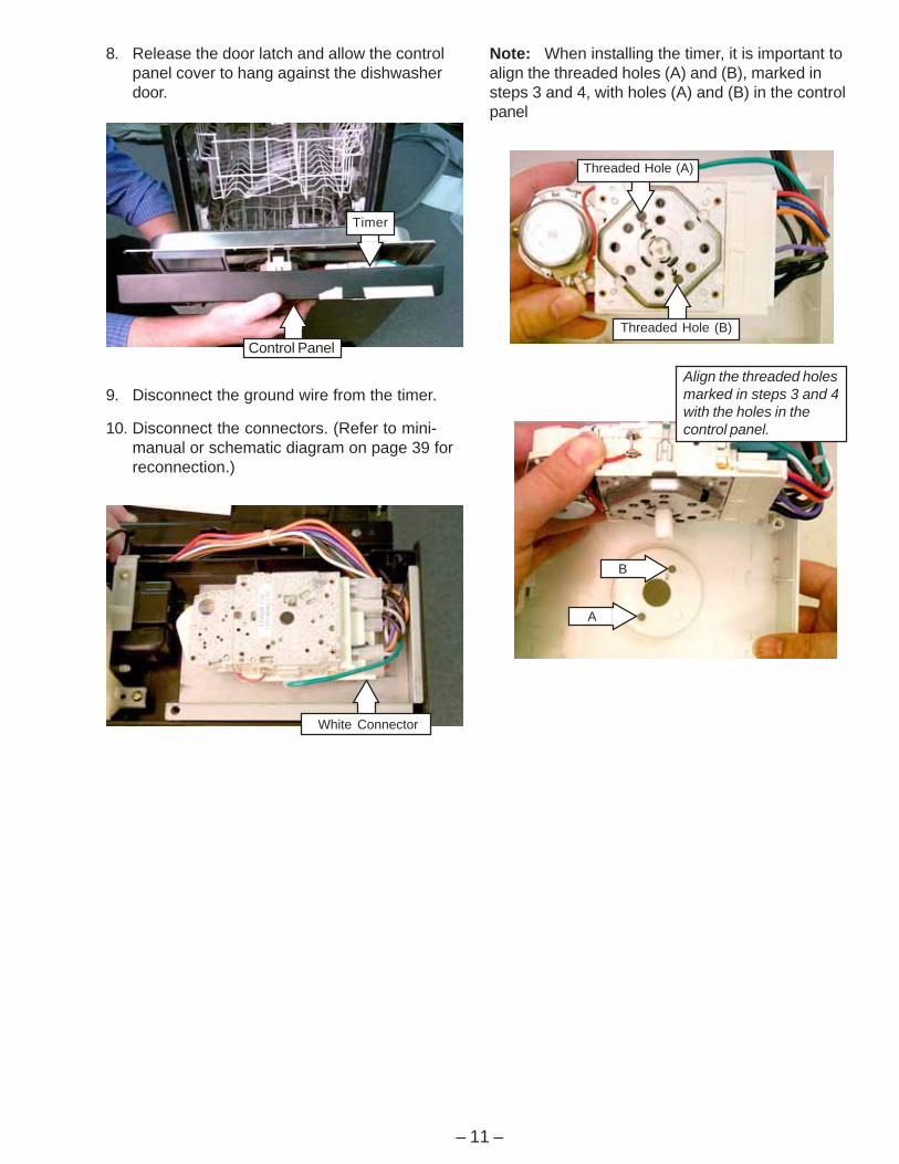
8. Release the door latch and allow the controlpanel cover to hang against the dishwasherdoor.
9. Disconnect the ground wire from the timer.
10. Disconnect the connectors. (Refer to mini-manual or schematic diagram on page 39 forreconnection.)
Note: When installing the timer, it is important toalign the threaded holes (A) and (B), marked insteps 3 and 4, with holes (A) and (B) in the controlpanel
Timer
Control Panel
White Connector
Threaded Hole (A)
Threaded Hole (B)
B
A
Align the threaded holesmarked in steps 3 and 4with the holes in thecontrol panel.
– 12 –
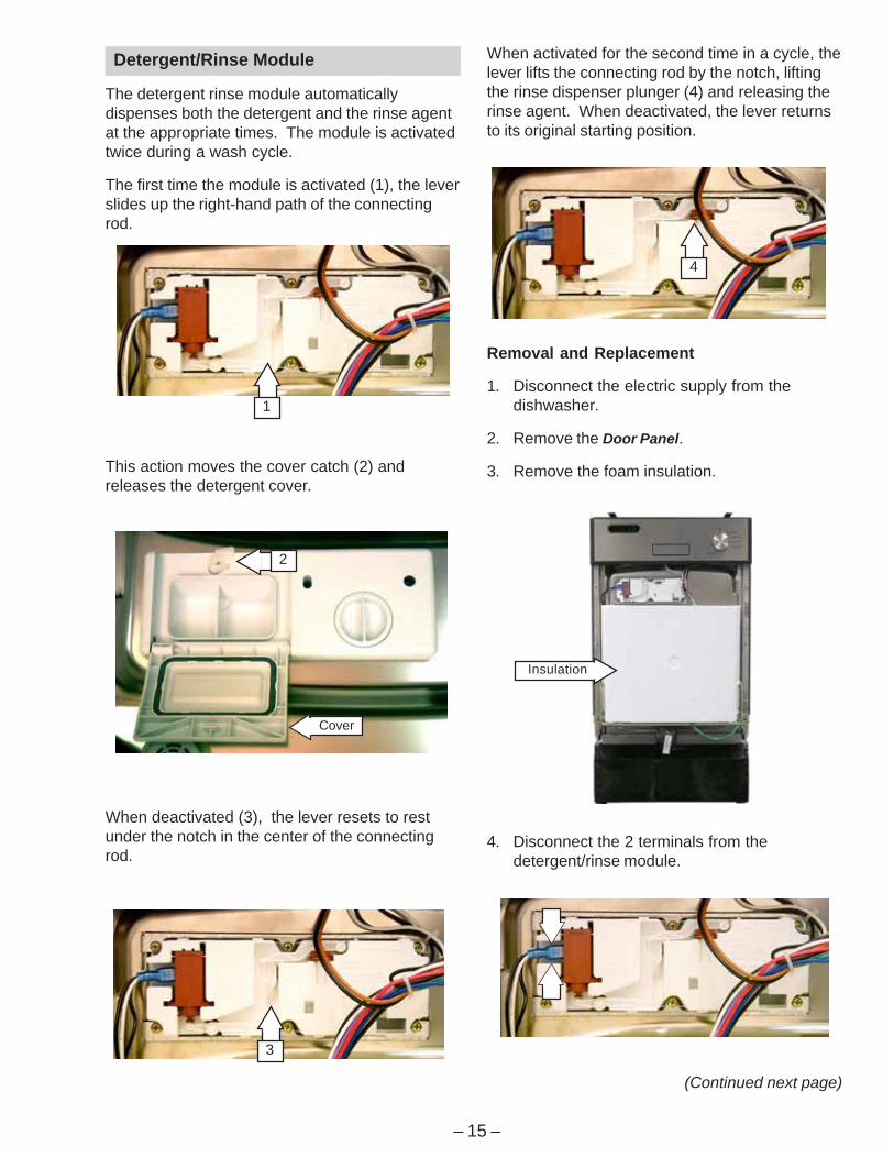
9. Remove the door switch from the door latchmounting bracket.
10. Inspect the door latch spring. Make sure thedoor latch flap fits properly in the door latchflap hole. If the spring is misaligned, broken,or missing, insert a new spring in the springpost holes.
Bracket
Switch
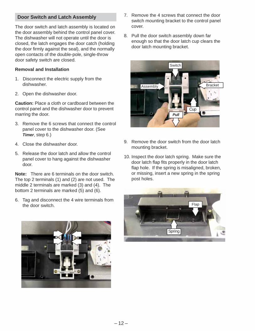
7. Remove the 4 screws that connect the doorswitch mounting bracket to the control panelcover.
8. Pull the door switch assembly down farenough so that the door latch cup clears thedoor latch mounting bracket.
Assembly
Door Switch and Latch Assembly
The door switch and latch assembly is located onthe door assembly behind the control panel cover.The dishwasher will not operate until the door isclosed, the latch engages the door catch (holdingthe door firmly against the seal), and the normallyopen contacts of the double-pole, single-throwdoor safety switch are closed.
Removal and Installation
1. Disconnect the electric supply from thedishwasher.
2. Open the dishwasher door.
Caution: Place a cloth or cardboard between thecontrol panel and the dishwasher door to preventmarring the door.
3. Remove the 6 screws that connect the controlpanel cover to the dishwasher door. (SeeTimer, step 6.)
4. Close the dishwasher door.
5. Release the door latch and allow the controlpanel cover to hang against the dishwasherdoor.
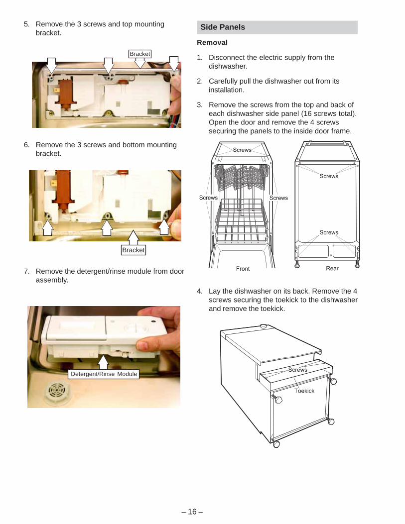
Note: There are 6 terminals on the door switch.The top 2 terminals (1) and (2) are not used. Themiddle 2 terminals are marked (3) and (4). Thebottom 2 terminals are marked (5) and (6).
6. Tag and disconnect the 4 wire terminals fromthe door switch.
PullCup
Flap
Spring

– 13 –
5. Inspect the o-ring. If the o-ring shows obvioussigns of wear or damage, replace the channelassembly.
6. Inspect the gasket on the channel assembly.If the gasket shows obvious signs of wear ordamage, replace the channel assembly.
Channel
O-Ring
Gasket
Static Dry System
The static dry system operates through a ventlocated in the control panel. The vent allows hotair to exit the dishwasher tub and graduallyremove moisture.
Removal
1. Open the dishwasher door.
2. Remove the 6 screws that connect the controlpanel cover to the dishwasher door. (SeeTimer, step 6.)
3. Release the door latch and allow the controlpanel cover to hang against the dishwasherdoor.
4. Remove the static vent channel cover andassembly as shown below. Inspect the coverfor hard water/lime deposits or debris, andclean if necessary.
Cover
(Continued next page)
Installation
1. Insert the static vent channel through thestatic vent door hole.
Hole
Channel
2. Install the static vent cover to the static ventchannel, and position the control panel coveron the dishwasher door.

– 14 –
Door Panel
Note: Make sure the edge of the control panelcover is flush with the edge of the door.
3. Align the screw holes on the control panel withthe screw holes on the dishwasher door.
4. Install the 6 screws that connect the controlpanel cover to the dishwasher door.
Cover
Make sure the edgeof the control panelcover is flush withthe edge of the door.
Door Panel
The door panel covers the door to the dishwasherand protects the detergent/rinse moduleelectronics.
Removal
1. Disconnect the electric supply from thedishwasher.
2. Open the dishwasher door.
3. Remove the 6 screws and the door panelfrom the door assembly. Do not remove the 6screws that hold the control panel cover to thedoor assembly.
– 15 –
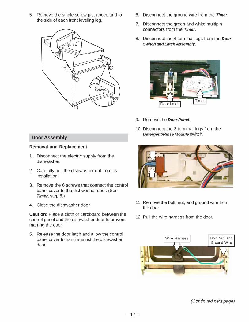
This action moves the cover catch (2) andreleases the detergent cover.
When deactivated (3), the lever resets to restunder the notch in the center of the connectingrod.
When activated for the second time in a cycle, thelever lifts the connecting rod by the notch, liftingthe rinse dispenser plunger (4) and releasing therinse agent. When deactivated, the lever returnsto its original starting position.
Removal and Replacement
1. Disconnect the electric supply from thedishwasher.
2. Remove the Door Panel.
3. Remove the foam insulation.
Cover
Detergent/Rinse Module
The detergent rinse module automaticallydispenses both the detergent and the rinse agentat the appropriate times. The module is activatedtwice during a wash cycle.
The first time the module is activated (1), the leverslides up the right-hand path of the connectingrod.
1
4
3
2
Insulation
4. Disconnect the 2 terminals from thedetergent/rinse module.
(Continued next page)
– 16 –
5. Remove the 3 screws and top mountingbracket.
6. Remove the 3 screws and bottom mountingbracket.
7. Remove the detergent/rinse module from doorassembly.
Side Panels
Removal
1. Disconnect the electric supply from thedishwasher.
2. Carefully pull the dishwasher out from itsinstallation.
3. Remove the screws from the top and back ofeach dishwasher side panel (16 screws total).Open the door and remove the 4 screwssecuring the panels to the inside door frame.
4. Lay the dishwasher on its back. Remove the 4screws securing the toekick to the dishwasherand remove the toekick.
Detergent/Rinse Module
Bracket
Bracket
– 17 –
9. Remove the Door Panel.
10. Disconnect the 2 terminal lugs from theDetergent/Rinse Module switch.
Door Assembly
Removal and Replacement
1. Disconnect the electric supply from thedishwasher.
2. Carefully pull the dishwasher out from itsinstallation.
3. Remove the 6 screws that connect the controlpanel cover to the dishwasher door. (SeeTimer, step 6.)
4. Close the dishwasher door.
Caution: Place a cloth or cardboard between thecontrol panel and the dishwasher door to preventmarring the door.
5. Release the door latch and allow the controlpanel cover to hang against the dishwasherdoor.
TimerDoor Latch
5. Remove the single screw just above and tothe side of each front leveling leg.
6. Disconnect the ground wire from the Timer.
7. Disconnect the green and white multipinconnectors from the Timer.
8. Disconnect the 4 terminal lugs from the DoorSwitch and Latch Assembly.
11. Remove the bolt, nut, and ground wire fromthe door.
12. Pull the wire harness from the door.
Bolt, Nut, andGround Wire
Wire Harness
(Continued next page)
– 18 –
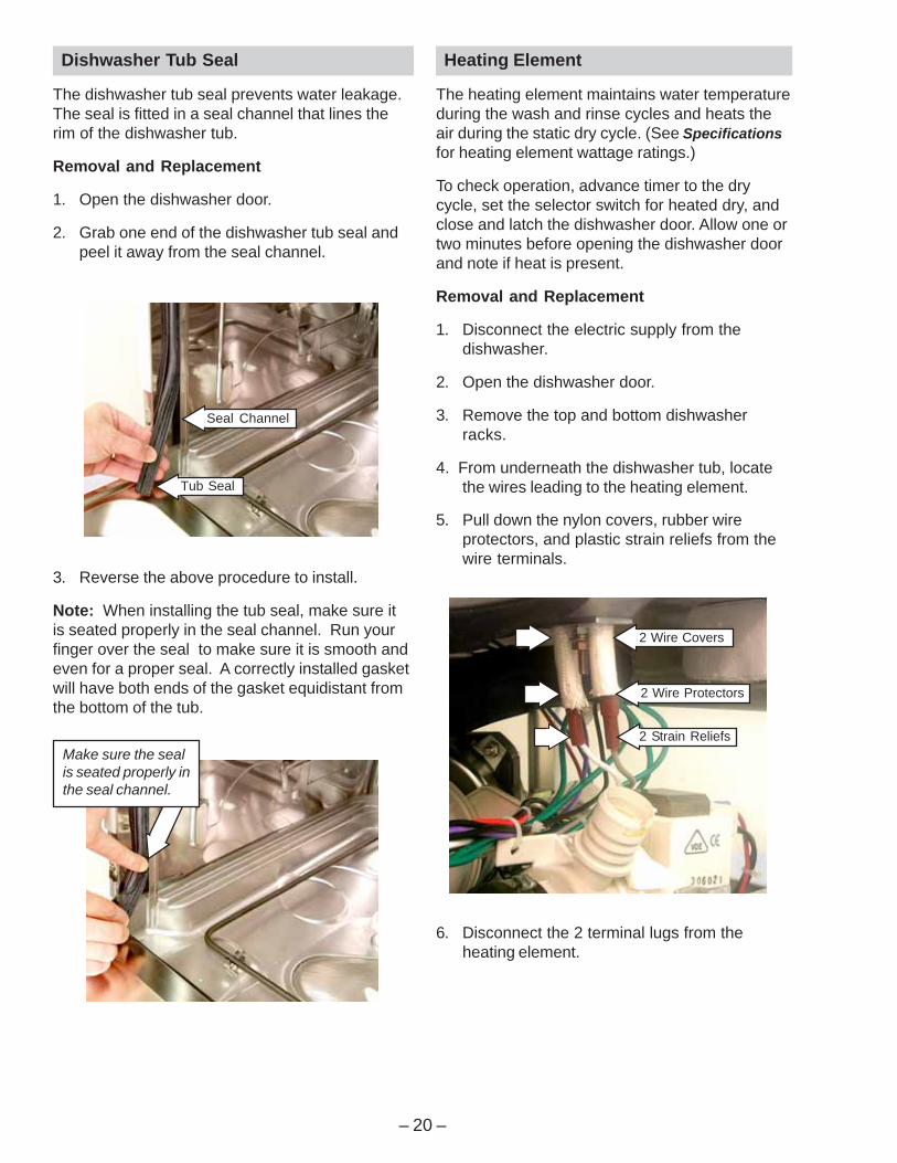
Caution: The star washer is easily damagedduring removal and should not be reused. Ordera new set of star washers (part number:WD01X10254).
21. Remove the star washer from thedishwasher door hinge.
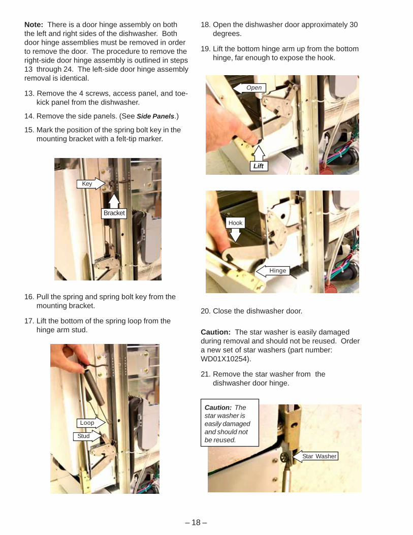
16. Pull the spring and spring bolt key from themounting bracket.
17. Lift the bottom of the spring loop from thehinge arm stud.
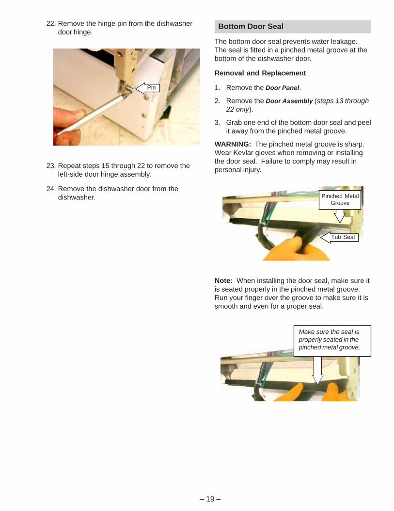
18. Open the dishwasher door approximately 30degrees.
19. Lift the bottom hinge arm up from the bottomhinge, far enough to expose the hook.
Note: There is a door hinge assembly on boththe left and right sides of the dishwasher. Bothdoor hinge assemblies must be removed in orderto remove the door. The procedure to remove theright-side door hinge assembly is outlined in steps13 through 24. The left-side door hinge assemblyremoval is identical.
13. Remove the 4 screws, access panel, and toe-kick panel from the dishwasher.
14. Remove the side panels. (See Side Panels.)
15. Mark the position of the spring bolt key in themounting bracket with a felt-tip marker.
Key
Bracket
Loop
Stud
20. Close the dishwasher door.
Open
Lift
Hinge
Hook
Caution: Thestar washer iseasily damagedand should notbe reused.
Star Washer
– 19 –
23. Repeat steps 15 through 22 to remove theleft-side door hinge assembly.
24. Remove the dishwasher door from thedishwasher.
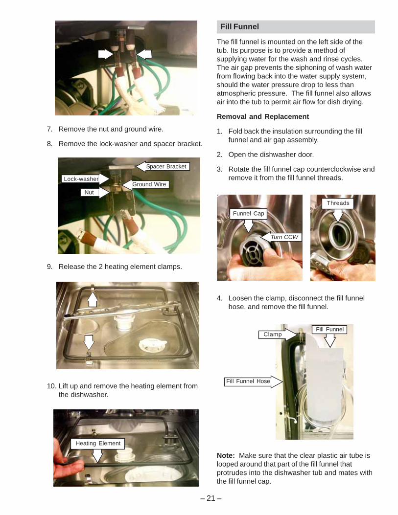
22. Remove the hinge pin from the dishwasherdoor hinge.
Note: When installing the door seal, make sure itis seated properly in the pinched metal groove.Run your finger over the groove to make sure it issmooth and even for a proper seal.
Bottom Door Seal
The bottom door seal prevents water leakage.The seal is fitted in a pinched metal groove at thebottom of the dishwasher door.
Removal and Replacement
1. Remove the Door Panel.
2. Remove the Door Assembly (steps 13 through22 only).
3. Grab one end of the bottom door seal and peelit away from the pinched metal groove.
WARNING: The pinched metal groove is sharp.Wear Kevlar gloves when removing or installingthe door seal. Failure to comply may result inpersonal injury.
Pin
Tub Seal
Pinched MetalGroove
Make sure the seal isproperly seated in thepinched metal groove.
– 20 –
6. Disconnect the 2 terminal lugs from theheating element.
3. Reverse the above procedure to install.
Note: When installing the tub seal, make sure itis seated properly in the seal channel. Run yourfinger over the seal to make sure it is smooth andeven for a proper seal. A correctly installed gasketwill have both ends of the gasket equidistant fromthe bottom of the tub.
Tub Seal
Seal Channel
Dishwasher Tub Seal
The dishwasher tub seal prevents water leakage.The seal is fitted in a seal channel that lines therim of the dishwasher tub.
Removal and Replacement
1. Open the dishwasher door.
2. Grab one end of the dishwasher tub seal andpeel it away from the seal channel.
Heating Element
The heating element maintains water temperatureduring the wash and rinse cycles and heats theair during the static dry cycle. (See Specificationsfor heating element wattage ratings.)
To check operation, advance timer to the drycycle, set the selector switch for heated dry, andclose and latch the dishwasher door. Allow one ortwo minutes before opening the dishwasher doorand note if heat is present.
Removal and Replacement
1. Disconnect the electric supply from thedishwasher.
2. Open the dishwasher door.
3. Remove the top and bottom dishwasherracks.
4. From underneath the dishwasher tub, locatethe wires leading to the heating element.
5. Pull down the nylon covers, rubber wireprotectors, and plastic strain reliefs from thewire terminals.
Make sure the sealis seated properly inthe seal channel.
2 Wire Covers
2 Wire Protectors
2 Strain Reliefs
– 21 –
7. Remove the nut and ground wire.
8. Remove the lock-washer and spacer bracket.
10. Lift up and remove the heating element fromthe dishwasher.
9. Release the 2 heating element clamps.
Fill Funnel
The fill funnel is mounted on the left side of thetub. Its purpose is to provide a method ofsupplying water for the wash and rinse cycles.The air gap prevents the siphoning of wash waterfrom flowing back into the water supply system,should the water pressure drop to less thanatmospheric pressure. The fill funnel also allowsair into the tub to permit air flow for dish drying.
Removal and Replacement
1. Fold back the insulation surrounding the fillfunnel and air gap assembly.
2. Open the dishwasher door.
3. Rotate the fill funnel cap counterclockwise andremove it from the fill funnel threads.
Heating Element
Turn CCW
Funnel Cap
Threads
4. Loosen the clamp, disconnect the fill funnelhose, and remove the fill funnel.
Note: Make sure that the clear plastic air tube islooped around that part of the fill funnel thatprotrudes into the dishwasher tub and mates withthe fill funnel cap.
Fill Funnel Hose
Fill FunnelClamp
Ground Wire
Spacer Bracket
Lock-washer
Nut
– 22 –
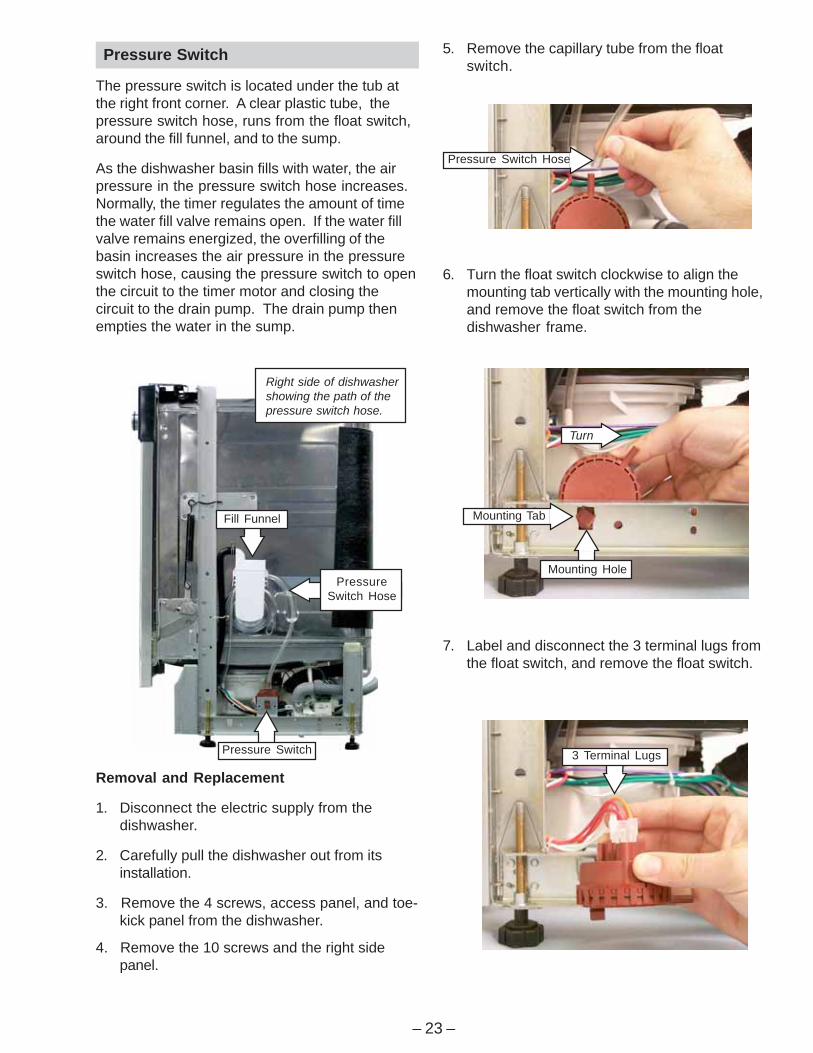
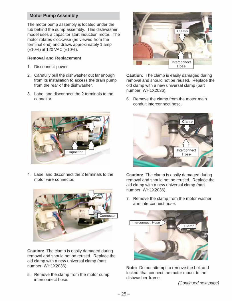
7. Remove the 4 screws and water fill valve fromthe mounting bracket. Retain the mountingbracket and screws.
Mounting Bracket
6. Disconnect the 2 terminal lugs from the waterfill valve assembly.
3. Disconnect the incoming water line from thewater fill valve port.
4. Remove the 2 screws and mounting bracketfrom the dishwasher.
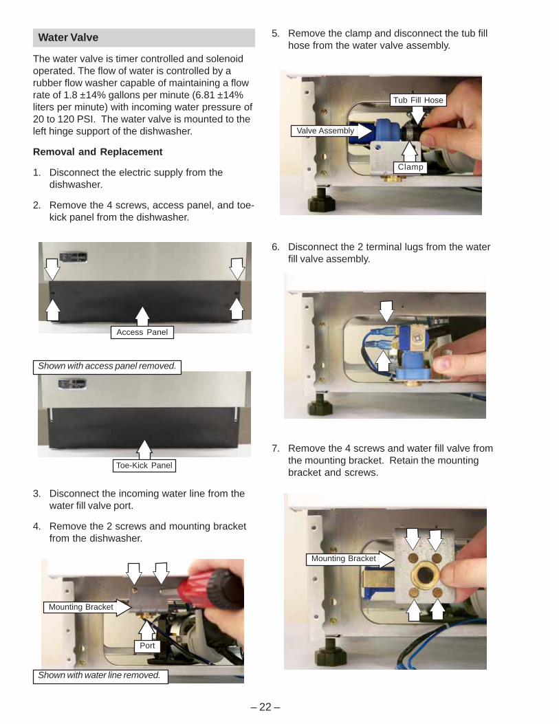
5. Remove the clamp and disconnect the tub fillhose from the water valve assembly.
Valve Assembly
Water Valve
The water valve is timer controlled and solenoidoperated. The flow of water is controlled by arubber flow washer capable of maintaining a flowrate of 1.8 ±14% gallons per minute (6.81 ±14%liters per minute) with incoming water pressure of20 to 120 PSI. The water valve is mounted to theleft hinge support of the dishwasher.
Removal and Replacement
1. Disconnect the electric supply from thedishwasher.
2. Remove the 4 screws, access panel, and toe-kick panel from the dishwasher.
Clamp
Tub Fill Hose
Access Panel
Toe-Kick Panel
Shown with access panel removed.
Mounting Bracket
Port
Shown with water line removed.
– 23 –
Removal and Replacement
1. Disconnect the electric supply from thedishwasher.
2. Carefully pull the dishwasher out from itsinstallation.
3. Remove the 4 screws, access panel, and toe-kick panel from the dishwasher.
4. Remove the 10 screws and the right sidepanel.
Pressure Switch
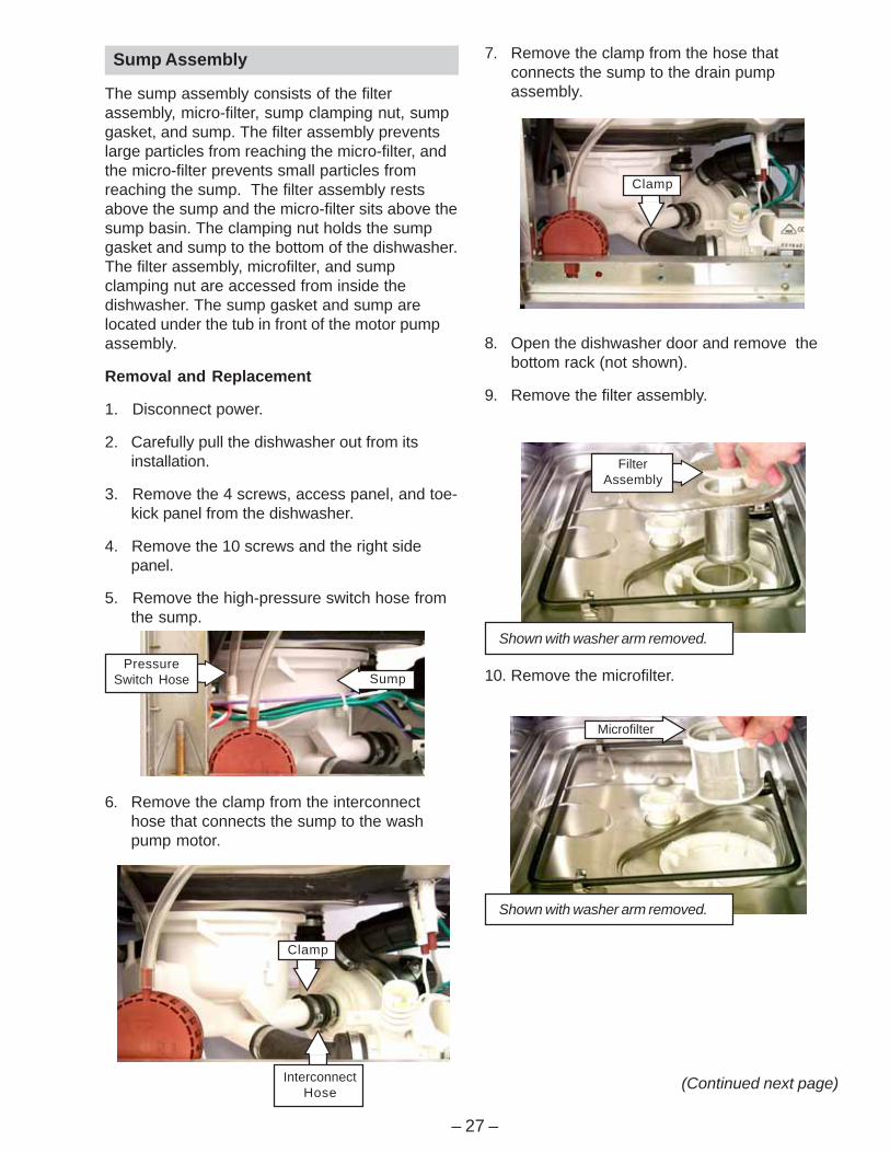
The pressure switch is located under the tub atthe right front corner. A clear plastic tube, thepressure switch hose, runs from the float switch,around the fill funnel, and to the sump.
As the dishwasher basin fills with water, the airpressure in the pressure switch hose increases.Normally, the timer regulates the amount of timethe water fill valve remains open. If the water fillvalve remains energized, the overfilling of thebasin increases the air pressure in the pressureswitch hose, causing the pressure switch to openthe circuit to the timer motor and closing thecircuit to the drain pump. The drain pump thenempties the water in the sump.
7. Label and disconnect the 3 terminal lugs fromthe float switch, and remove the float switch.
6. Turn the float switch clockwise to align themounting tab vertically with the mounting hole,and remove the float switch from thedishwasher frame.
5. Remove the capillary tube from the floatswitch.
Pressure Switch Hose
3 Terminal Lugs
Turn
Mounting Tab
Mounting Hole
Fill Funnel
PressureSwitch Hose
Pressure Switch
Right side of dishwashershowing the path of thepressure switch hose.

– 24 –
8. Remove and save the 2 screws, lock-washers, mounting bracket, and nut platefrom the drain pump.
Caution: The clamp is easily damaged duringremoval and should not be reused. Replace theold clamp with a new universal clamp (partnumber: WH1X2036).
6. Remove the clamp from the sumpinterconnect hose.
7. Remove the drain pump from the sumpinterconnect hose.
5. Remove the 2 bolts, lock-washers, and nuts.
Mounting Bracket
Nut Plate
2 Screws2 Lock-washers
6. Label and disconnect the 2 terminal lugs fromthe drain pump.
Drain Pump Assembly
The drain pump assembly is located under the tubat the right rear corner. The drain pump operateson 120 VAC and is energized 60 seconds after thewash pump shuts down, to remove any water inthe dishwasher sump. The drain pump forces thewater out the drain line. A check valve flapper onthe drain pump prevents the dirty water fromreentering the sump.
Removal and Replacement
1. Disconnect the electric supply from thedishwasher.
2. Carefully pull the dishwasher out from itsinstallation.
3. Remove the 4 screws, access panel, and toe-kick panel from the dishwasher.
4. Remove the 10 screws and the right sidepanel.
5. Remove the drain tube (not shown) from thedrain pump port.
Port
Drain Pump
InterconnectHose
Clamp
– 25 –
4. Label and disconnect the 2 terminals to themotor wire connector.
Motor Pump Assembly
The motor pump assembly is located under thetub behind the sump assembly. This dishwashermodel uses a capacitor start induction motor. Themotor rotates clockwise (as viewed from theterminal end) and draws approximately 1 amp(±10%) at 120 VAC (±10%).
Removal and Replacement
1. Disconnect power.
2. Carefully pull the dishwasher out far enoughfrom its installation to access the drain pumpfrom the rear of the dishwasher.
3. Label and disconnect the 2 terminals to thecapacitor.
Caution: The clamp is easily damaged duringremoval and should not be reused. Replace theold clamp with a new universal clamp (partnumber: WH1X2036).
6. Remove the clamp from the motor mainconduit interconnect hose.
Caution: The clamp is easily damaged duringremoval and should not be reused. Replace theold clamp with a new universal clamp (partnumber: WH1X2036).
5. Remove the clamp from the motor sumpinterconnect hose.
Note: Do not attempt to remove the bolt andlocknut that connect the motor mount to thedishwasher frame.
Caution: The clamp is easily damaged duringremoval and should not be reused. Replace theold clamp with a new universal clamp (partnumber: WH1X2036).
7. Remove the clamp from the motor washerarm interconnect hose.
Clamp
InterconnectHose
Interconnect HoseClamp
(Continued next page)
Clamp
InterconnectHose
Capacitor
Connector

– 26 –
9. Pull the motor mount back far enough to clearthe motor tab, work the motor from theattaching hoses, and remove the motor pumpassembly from the dishwasher.
8. Remove the screw and disconnect the groundwire from the wash pump motor assembly.
Locknut
As seen from right sideof dishwasher.
Bolt
Ground Wire
As seen from rearof dishwasher.
Pull Out
Pull Out
Motor TabMotor Mount
Motor PumpAssembly
– 27 –
6. Remove the clamp from the interconnecthose that connects the sump to the washpump motor.
Sump Assembly
The sump assembly consists of the filterassembly, micro-filter, sump clamping nut, sumpgasket, and sump. The filter assembly preventslarge particles from reaching the micro-filter, andthe micro-filter prevents small particles fromreaching the sump. The filter assembly restsabove the sump and the micro-filter sits above thesump basin. The clamping nut holds the sumpgasket and sump to the bottom of the dishwasher.The filter assembly, microfilter, and sumpclamping nut are accessed from inside thedishwasher. The sump gasket and sump arelocated under the tub in front of the motor pumpassembly.
Removal and Replacement
1. Disconnect power.
2. Carefully pull the dishwasher out from itsinstallation.
3. Remove the 4 screws, access panel, and toe-kick panel from the dishwasher.
4. Remove the 10 screws and the right sidepanel.
5. Remove the high-pressure switch hose fromthe sump.
10. Remove the microfilter.
7. Remove the clamp from the hose thatconnects the sump to the drain pumpassembly.
8. Open the dishwasher door and remove thebottom rack (not shown).
9. Remove the filter assembly.
Shown with washer arm removed.
Microfilter
(Continued next page)
Shown with washer arm removed.
FilterAssembly
Clamp
InterconnectHose
Clamp
PressureSwitch Hose Sump
– 28 –
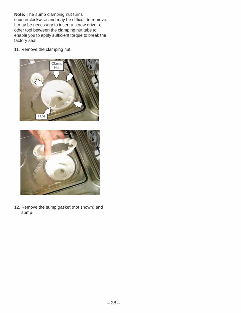
Note: The sump clamping nut turnscounterclockwise and may be difficult to remove.It may be necessary to insert a screw driver orother tool between the clamping nut tabs toenable you to apply sufficient torque to break thefactory seal.
11. Remove the clamping nut.
12. Remove the sump gasket (not shown) andsump.
ClampNut
Tabs
– 29 –
Troubleshooting
WARNING: Always turn off the electric powersupply before servicing any electrical component,making ohmmeter checks, or replacing any parts.
Note: All voltage checks should be made with avoltmeter having a full-scale range of 130 volts orhigher. After service is completed, be sure allsafety grounding circuits are complete, allelectrical connections are secure, and all accesspanels are in place.
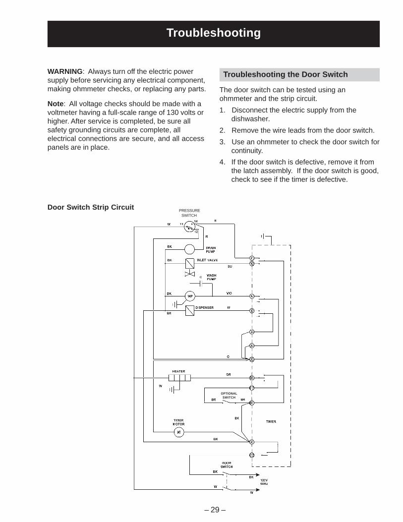
Troubleshooting the Door Switch
The door switch can be tested using anohmmeter and the strip circuit.
1. Disconnect the electric supply from thedishwasher.
2. Remove the wire leads from the door switch.
3. Use an ohmmeter to check the door switch forcontinuity.
4. If the door switch is defective, remove it fromthe latch assembly. If the door switch is good,check to see if the timer is defective.
Door Switch Strip CircuitSWITCH
PRESSURE
OPTIONALSWITCH
– 30 –
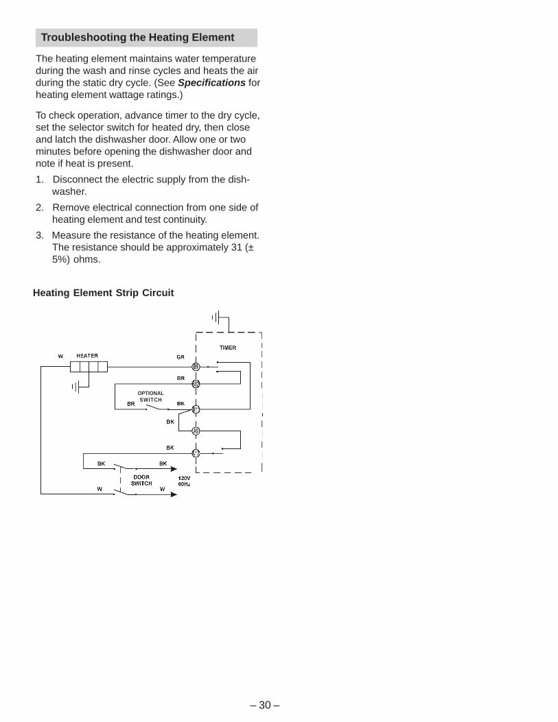
Heating Element Strip Circuit
Troubleshooting the Heating Element
The heating element maintains water temperatureduring the wash and rinse cycles and heats the airduring the static dry cycle. (See Specifications forheating element wattage ratings.)
To check operation, advance timer to the dry cycle,set the selector switch for heated dry, then closeand latch the dishwasher door. Allow one or twominutes before opening the dishwasher door andnote if heat is present.
1. Disconnect the electric supply from the dish-washer.
2. Remove electrical connection from one side ofheating element and test continuity.
3. Measure the resistance of the heating element.The resistance should be approximately 31 (±5%) ohms.
OPTIONALSWITCH
– 31 –
1
DRYING HEATING
PROGRAMME START
B12
INLET VALVEA1
DISPENSER
B11 WASH HEATING
B2
A12 BUS
WASH PUMP
A2
Pos
2 3 4 5 6
5 10 15 20 25 30 35 40 45 50 55 60
DRAIN PUMP
A7
POST&PAN
6MIN.
HEAVY WASH
6MIN.
NORMAL WASH
6MIN.
LIGHT WASH
24MIN. 14MIN.
RINSE&HOLD
36MIN.
HEAT DRY
6MIN.6MIN.RINSE RINSE RINSE RINSE WASH RINSE
DRYHOT OR COOL
CYCLE
SWITCH
F E
COOL DRY
X
O
O
X
RINSE
DRY
RINSE6MIN.
A3
B9
B3
A9
A4
CHINA CRYSTAL
7
RES
ET
VIO
BUR
BK
W
BKBR
COLOR FUNCTIONLOC
Timer Cycle Chart
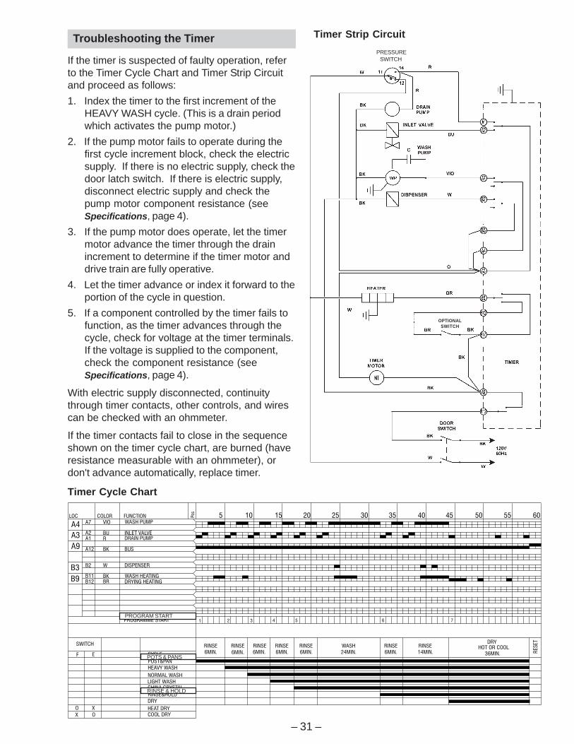
Troubleshooting the Timer
If the timer is suspected of faulty operation, referto the Timer Cycle Chart and Timer Strip Circuitand proceed as follows:
1. Index the timer to the first increment of theHEAVY WASH cycle. (This is a drain periodwhich activates the pump motor.)
2. If the pump motor fails to operate during thefirst cycle increment block, check the electricsupply. If there is no electric supply, check thedoor latch switch. If there is electric supply,disconnect electric supply and check thepump motor component resistance (seeSpecifications, page 4).
3. If the pump motor does operate, let the timermotor advance the timer through the drainincrement to determine if the timer motor anddrive train are fully operative.
4. Let the timer advance or index it forward to theportion of the cycle in question.
5. If a component controlled by the timer fails tofunction, as the timer advances through thecycle, check for voltage at the timer terminals.If the voltage is supplied to the component,check the component resistance (seeSpecifications, page 4).
With electric supply disconnected, continuitythrough timer contacts, other controls, and wirescan be checked with an ohmmeter.
If the timer contacts fail to close in the sequenceshown on the timer cycle chart, are burned (haveresistance measurable with an ohmmeter), ordon't advance automatically, replace timer.
PROGRAM START
POTS & PANS
RINSE & HOLD
Timer Strip Circuit
SWITCHPRESSURE
OPTIONALSWITCH
– 32 –
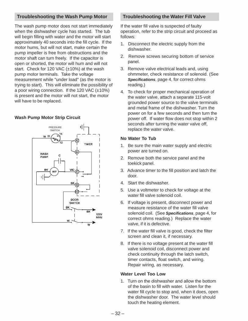
Troubleshooting the Wash Pump Motor
The wash pump motor does not start immediatelywhen the dishwasher cycle has started. The tubwill begin filling with water and the motor will startapproximately 40 seconds into the fill cycle. If themotor hums, but will not start, make certain thepump impeller is free from obstructions and themotor shaft can turn freely. If the capacitor isopen or shorted, the motor will hum and will notstart. Check for 120 VAC (±10%) at the washpump motor terminals. Take the voltagemeasurement while "under load" (as the motor istrying to start). This will eliminate the possibility ofa poor wiring connection. If the 120 VAC (±10%)is present and the motor will not start, the motorwill have to be replaced.
Troubleshooting the Water Fill Valve
If the water fill valve is suspected of faultyoperation, refer to the strip circuit and proceed asfollows:
1. Disconnect the electric supply from thedishwasher.
2. Remove screws securing bottom of servicepanel.
3. Remove valve electrical leads and, usingohmmeter, check resistance of solenoid. (SeeSpecifications, page 4, for correct ohmsreading.)
4. To check for proper mechanical operation ofthe water valve, attach a separate 115-voltgrounded power source to the valve terminalsand metal frame of the dishwasher. Turn thepower on for a few seconds and then turn thepower off. If water flow does not stop within 2seconds after turning the water valve off,replace the water valve.
No Water To Tub
1. Be sure the main water supply and electricpower are turned on.
2. Remove both the service panel and thetoekick panel.
3. Advance timer to the fill position and latch thedoor.
4. Start the dishwasher.
5. Use a voltmeter to check for voltage at thewater fill valve solenoid coil.
6. If voltage is present, disconnect power andmeasure resistance of the water fill valvesolenoid coil. (See Specifications, page 4, forcorrect ohms reading.) Replace the watervalve, if it is defective.
7. If the water fill valve is good, check the filterscreen and clean it, if necessary.
8. If there is no voltage present at the water fillvalve solenoid coil, disconnect power andcheck continuity through the latch switch,timer contacts, float switch, and wiring.Repair wiring, as necessary.
Water Level Too Low
1. Turn on the dishwasher and allow the bottomof the basin to fill with water. Listen for thewater fill cycle to stop and, when it does, openthe dishwasher door. The water level shouldtouch the heating element.
Wash Pump Motor Strip Circuit
SWITCHPRESSURE
– 33 –
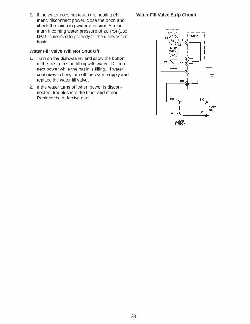
2. If the water does not touch the heating ele-ment, disconnect power, close the door, andcheck the incoming water pressure. A mini-mum incoming water pressure of 20 PSI (138kPa) is needed to properly fill the dishwasherbasin.
Water Fill Valve Will Not Shut Off
1. Turn on the dishwasher and allow the bottomof the basin to start filling with water. Discon-nect power while the basin is filling. If watercontinues to flow, turn off the water supply andreplace the water fill valve.
2. If the water turns off when power is discon-nected, troubleshoot the timer and motor.Replace the defective part.
Water Fill Valve Strip Circuit
SWITCHPRESSURE

– 34 –
Troubleshooting Checklist
The troubleshooting checklist is common for alldishwasher models. They use different parts toaccomplish the same thing and diagnosis willremain similar.
When a problem arises, and a possible cause islisted, follow the test and remove or replaceprocedures as outlined in this Technical ServiceManual.
The wiring diagram, schematic, and timer cyclechart are a necessity when making electricalchecks. In most cases, an ohmmeter will handleall the tests necessary.
To verify the setup of any particular cycle ofoperation, refer to the Owner's Manual.
SYMPTOM CHECK FOR THEFOLLOWING
REMEDY
1. A blown fuse or tripped circuitbreaker.
1. Replace the fuse or resetthe breaker.
2. Damaged or defective wiring. 2. Repair the wiring.3. Defective timer contacts. 3. Replace the timer.4. Improper motor resistances. 4. Replace the motor.5. Defective door switch contacts. 5. Replace the door switch.
Dishwasher will notoperate when turnedON.
6. Defective door latch. 6. Replace the door latch.1. Defective heat selector switch. 1. Replace the heat selector
switch.2. Heater element is open. 2. Replace the heater
element.3. Defective timer contacts. 3. Replace the timer.
Dishwasher runs butwill not heat.
4. Damaged or defective wiring. 4. Repair the wiring.1. Timer motor inoperative. 1. Replace the timer.2. Damaged or defective wiring. 2. Repair the wiring.
Dishwasher runs butwill not stop.
3. Defective timer. 3. Replace the timer.Dishwasher runs withdoor open.
1. Defective door safety switch. 1. Replace the door safetyswitch.
1. Defective motor bearings. 1. Replace the motor.2. Knob position advanced beyondfill.
2. Advance the knob to thenext wash cycle.
Motor hums but willnot start or run.
3. Defective motor capacitor. 3. Replace the motorcapacitor.
1. Improper motor voltage. 1. Replace the motor.2. Motor shaft binding. 2. Replace the motor.
Motor trips out oninternal thermaloverload protector. 3. Motor windings shorted. 3. Replace the motor.Repeated dishwashercycles.
1. Defective timer. 1. Replace the timer.
1. Timer motor is stalled or open. 1. Replace the timer.2. Timer not providing power to timermotor.
2. Replace the timer.Timer does notadvance automatically.
3. Timer shaft binding or knobinterference to escutcheon.
3. Repair or adjust timer shaftor knob.
Etching on glassware. 1. Soft water condition (Natural orartificial).
Have a sample of the wateranalyzed by the local waterdepartment.
Dishwasher continuesto fill even thoughthere is no voltage tothe fill valve (floodingcondition).
1. Defective water fill valve. 1. Replace the water fill valve.
2. Debris buildup under thediaphragm in the water fill valve.
2. Clean out the debris orreplace the water fill valve.
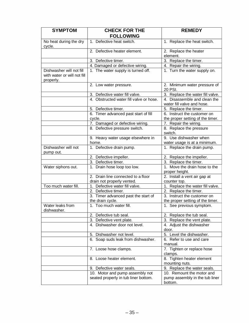
– 35 –
SYMPTOM CHECK FOR THEFOLLOWING
REMEDY
No heat during the drycycle.
1. Defective heat switch. 1. Replace the heat switch.
2. Defective heater element. 2. Replace the heaterelement.
3. Defective timer. 3. Replace the timer.4. Damaged or defective wiring. 4. Repair the wiring.
Dishwasher will not fillwith water or will not fillproperly.
1. The water supply is turned off. 1. Turn the water supply on.
2. Low water pressure. 2. Minimum water pressure of20 PSI.
3. Defective water fill valve. 3. Replace the water fill valve.4. Obstructed water fill valve or hose. 4. Disassemble and clean the
water fill valve and hose.5. Defective timer. 5. Replace the timer.6. Timer advanced past start of fillcycle.
6. Instruct the customer onthe proper setting of the timer.
7. Damaged or defective wiring. 7. Repair the wiring.8. Defective pressure switch. 8. Replace the pressure
switch.9. Heavy water usage elsewhere inhome.
9. Use dishwasher whenwater usage is at a minimum.
Dishwasher will notpump out.
1. Defective drain pump. 1. Replace the drain pump.
2. Defective impeller. 2. Replace the impeller.3. Defective timer. 3. Replace the timer.
Water siphons out. 1. Drain hose loop too low. 1. Move the drain hose to theproper height.
2. Drain line connected to a floordrain not properly vented.
2. Install a vent air gap atcounter top.
Too much water fill. 1. Defective water fill valve. 1. Replace the water fill valve.2. Defective timer. 2. Replace the timer.3. Timer advanced past the start ofthe drain cycle.
3. Instruct the customer onthe proper setting of the timer.
Water leaks fromdishwasher.
1. Too much water fill. 1. See previous symptom.
2. Defective tub seal. 2. Replace the tub seal.3. Defective vent plate. 3. Replace the vent plate.4. Dishwasher door not level. 4. Adjust the dishwasher
door.5. Dishwasher not level. 5. Level the dishwasher.6. Soap suds leak from dishwasher. 6. Refer to use and care
manual.7. Loose hose clamps. 7. Tighten or replace hose
clamps.8. Loose heater element. 8. Tighten heater element
mounting nuts.9. Defective water seals. 9. Replace the water seals.10. Motor and pump assembly notseated properly in tub liner bottom.
10. Remount the motor andpump assembly in the tub linerbottom.
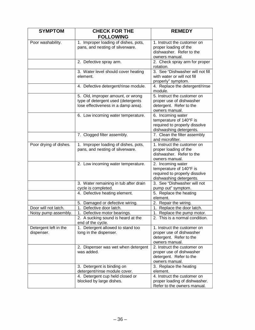
– 36 –
SYMPTOM CHECK FOR THEFOLLOWING
REMEDY
Poor washability. 1. Improper loading of dishes, pots,pans, and nesting of silverware.
1. Instruct the customer onproper loading of thedishwasher. Refer to theowners manual.
2. Defective spray arm. 2. Check spray arm for properrotation.
3. Water level should cover heatingelement.
3. See “Dishwasher will not fillwith water or will not fillproperly” symptom.
4. Defective detergent/rinse module. 4. Replace the detergent/rinsemodule.
5. Old, improper amount, or wrongtype of detergent used (detergentslose effectiveness in a damp area).
5. Instruct the customer onproper use of dishwasherdetergent. Refer to theowners manual.
6. Low incoming water temperature. 6. Incoming watertemperature of 140°F isrequired to properly dissolvedishwashing detergents.
7. Clogged filter assembly. 7. Clean the filter assemblyand microfilter.
Poor drying of dishes. 1. Improper loading of dishes, pots,pans, and nesting of silverware.
1. Instruct the customer onproper loading of thedishwasher. Refer to theowners manual.
2. Low incoming water temperature. 2. Incoming watertemperature of 140°F isrequired to properly dissolvedishwashing detergents.
3. Water remaining in tub after draincycle is completed.
3. See “Dishwasher will notpump out” symptom.
4. Defective heating element. 5. Replace the heatingelement.
5. Damaged or defective wiring. 2. Repair the wiring.Door will not latch. 1. Defective door latch. 1. Replace the door latch.Noisy pump assembly. 1. Defective motor bearings. 1. Replace the pump motor.
2. A sucking sound is heard at theend of the cycle.
2. This is a normal condition.
Detergent left in thedispenser.
1. Detergent allowed to stand toolong in the dispenser.
1. Instruct the customer onproper use of dishwasherdetergent. Refer to theowners manual.
2. Dispenser was wet when detergentwas added.
2. Instruct the customer onproper use of dishwasherdetergent. Refer to theowners manual.
3. Detergent is binding ondetergent/rinse module cover.
3. Replace the heatingelement.
4. Detergent cup held closed orblocked by large dishes.
4. Instruct the customer onproper loading of dishwasher.Refer to the owners manual.
– 37 –
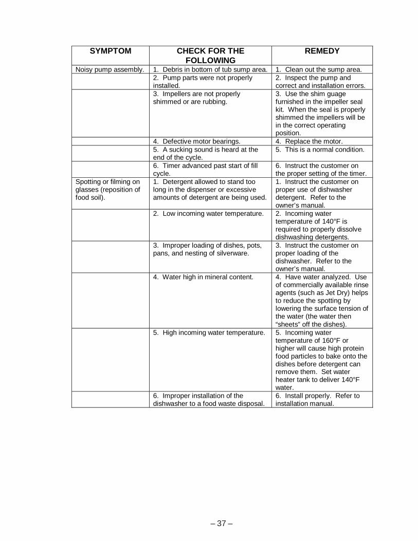
SYMPTOM CHECK FOR THEFOLLOWING
REMEDY
Noisy pump assembly. 1. Debris in bottom of tub sump area. 1. Clean out the sump area.2. Pump parts were not properlyinstalled.
2. Inspect the pump andcorrect and installation errors.
3. Impellers are not properlyshimmed or are rubbing.
3. Use the shim guagefurnished in the impeller sealkit. When the seal is properlyshimmed the impellers will bein the correct operatingposition.
4. Defective motor bearings. 4. Replace the motor.5. A sucking sound is heard at theend of the cycle.
5. This is a normal condition.
6. Timer advanced past start of fillcycle.
6. Instruct the customer onthe proper setting of the timer.
Spotting or filming onglasses (reposition offood soil).
1. Detergent allowed to stand toolong in the dispenser or excessiveamounts of detergent are being used.
1. Instruct the customer onproper use of dishwasherdetergent. Refer to theowner’s manual.
2. Low incoming water temperature. 2. Incoming watertemperature of 140°F isrequired to properly dissolvedishwashing detergents.
3. Improper loading of dishes, pots,pans, and nesting of silverware.
3. Instruct the customer onproper loading of thedishwasher. Refer to theowner’s manual.
4. Water high in mineral content. 4. Have water analyzed. Useof commercially available rinseagents (such as Jet Dry) helpsto reduce the spotting bylowering the surface tension ofthe water (the water then“sheets” off the dishes).
5. High incoming water temperature. 5. Incoming watertemperature of 160°F orhigher will cause high proteinfood particles to bake onto thedishes before detergent canremove them. Set waterheater tank to deliver 140°Fwater.
6. Improper installation of thedishwasher to a food waste disposal.
6. Install properly. Refer toinstallation manual.
– 38 –
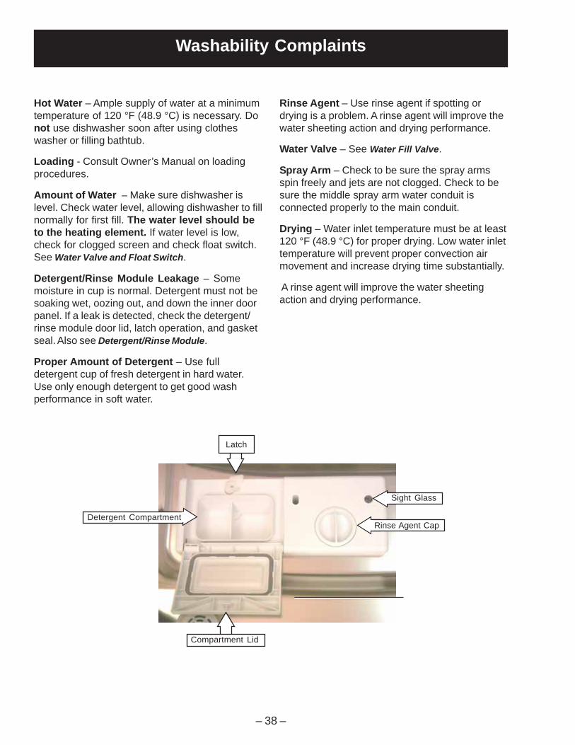
Washability Complaints
Hot Water – Ample supply of water at a minimumtemperature of 120 °F (48.9 °C) is necessary. Donot use dishwasher soon after using clotheswasher or filling bathtub.
Loading - Consult Owner’s Manual on loadingprocedures.
Amount of Water – Make sure dishwasher islevel. Check water level, allowing dishwasher to fillnormally for first fill. The water level should beto the heating element. If water level is low,check for clogged screen and check float switch.See Water Valve and Float Switch.
Detergent/Rinse Module Leakage – Somemoisture in cup is normal. Detergent must not besoaking wet, oozing out, and down the inner doorpanel. If a leak is detected, check the detergent/rinse module door lid, latch operation, and gasketseal. Also see Detergent/Rinse Module.
Proper Amount of Detergent – Use fulldetergent cup of fresh detergent in hard water.Use only enough detergent to get good washperformance in soft water.
Compartment Lid
Sight Glass
Rinse Agent Cap
Rinse Agent – Use rinse agent if spotting ordrying is a problem. A rinse agent will improve thewater sheeting action and drying performance.
Water Valve – See Water Fill Valve.
Spray Arm – Check to be sure the spray armsspin freely and jets are not clogged. Check to besure the middle spray arm water conduit isconnected properly to the main conduit.
Drying – Water inlet temperature must be at least120 °F (48.9 °C) for proper drying. Low water inlettemperature will prevent proper convection airmovement and increase drying time substantially.
A rinse agent will improve the water sheetingaction and drying performance.
Latch
Detergent Compartment
– 39 –
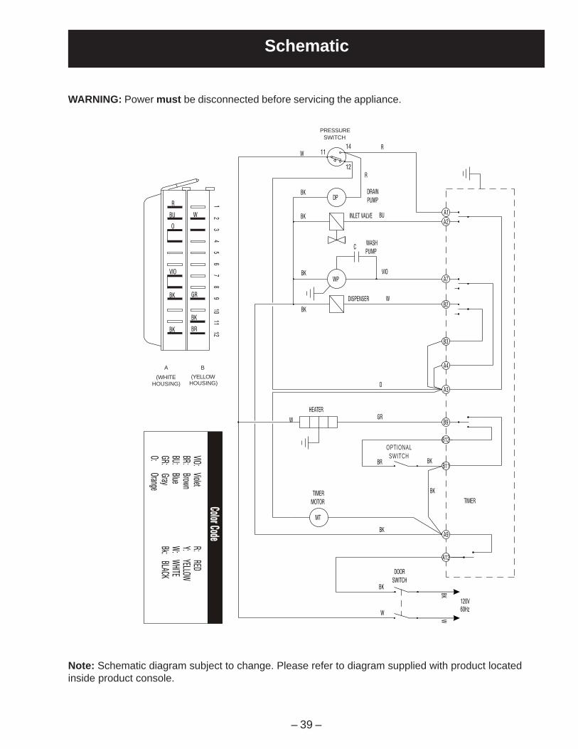
Schematic
WARNING: Power must be disconnected before servicing the appliance.
Note: Schematic diagram subject to change. Please refer to diagram supplied with product locatedinside product console.
BU
R
O
W 21
65
43
VIO
BK
BK
A
GR
BK
BR
109
87
1211
B
1114
12
BK
VIO:Violet
BR:Brown
BU:Blue
GR:Grayer
O:Orange
W
(WHITE
HOUSING)
(YELLOWHOUSEING)
FLOAT SWITCH
WR
INLET VALVE
DISPENSER
BK
BK
BK
BK
DP
WP
C
HEATER
DRAIN
PUMP
R
BU
WASH
PUMP
VIO
W
OPTION
SWITCH
O
BR
GR
R:RED
Y:YELLOW
W:
WHITE
Bk:BLACK
TIMER
MOTOR
MT
DOOR
SWITCH
BK
W
BK
BK
A1
A2
A7
B2
A4
B3
A3
B11
B12
B9
TIMER
A12
A9
BKW
ColorCode
ColorCode
120V60Hz
SWITCHPRESSURE
HOUSING)(WHITE
A
HOUSING)(YELLOW
B
OPTIONALSWITCH

– 40 –
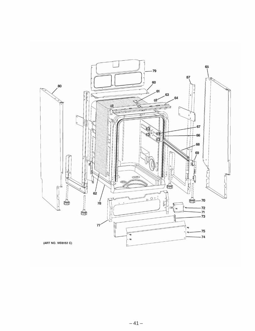
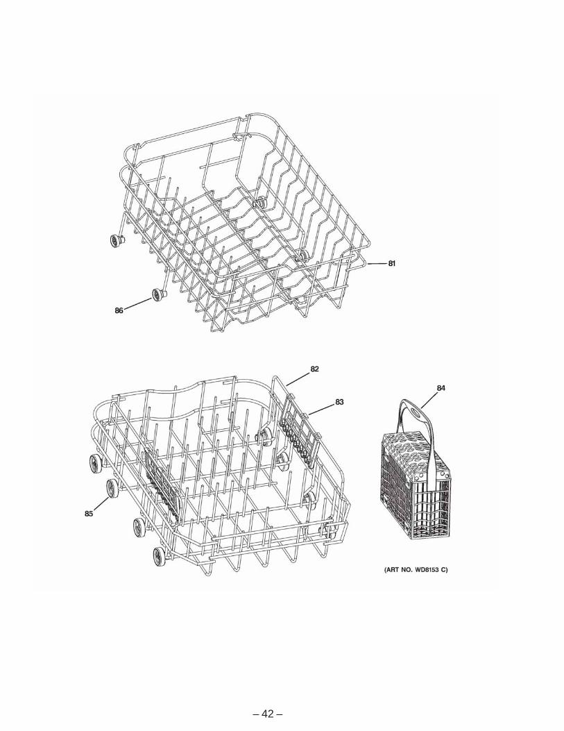
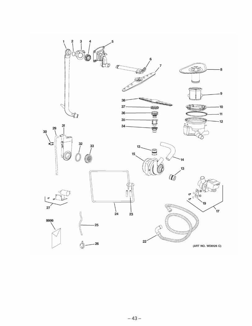
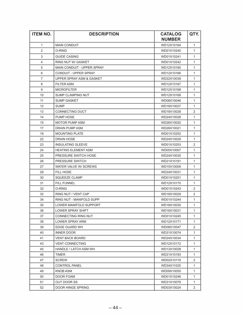
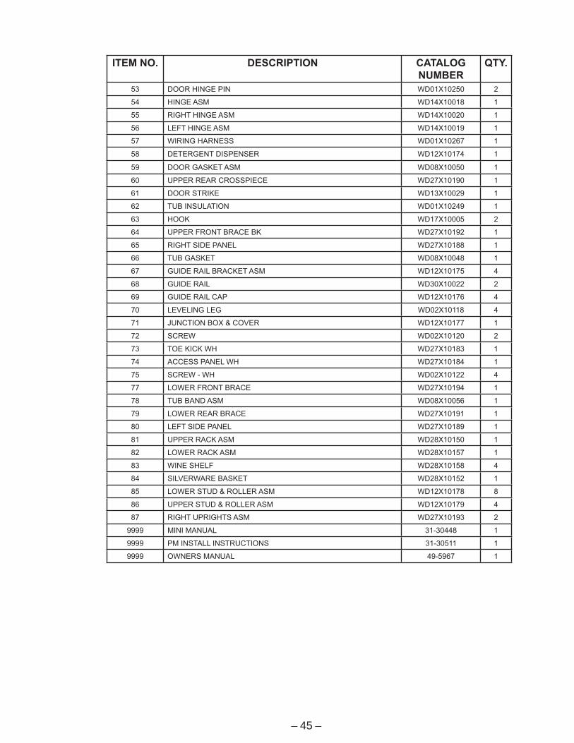
Illustrated Parts Catalog
– 41 –
– 42 –
– 43 –
– 44 –
ITEM NO. DESCRIPTION CATALOG NUMBER
QTY.
1 MAIN CONDUIT WD12X10164 1
2 O-RING WD01X10240 1
3 GUIDE CASING WD01X10241 1
4 RING NUT W/ GASKET WD01X10242 1
5 MAIN CONDUIT - UPPER SPRAY WD12X10165 1
6 CONDUIT - UPPER SPRAY WD12X10166 1
7 UPPER SPRAY ASM & GASKET WD22X10039 1
8 FILTER ASM WD12X10167 1
9 MICROFILTER WD12X10168 1
10 SUMP CLAMPING NUT WD12X10169 1
11 SUMP GASKET WD08X10046 1
12 SUMP WD18X10027 1
13 CONNECTING DUCT WD18X10028 2
14 PUMP HOSE WD24X10028 1
15 MOTOR PUMP ASM WD26X10020 1
17 DRAIN PUMP ASM WD26X10021 1
19 MOUNTING PLATE WD01X10252 1
22 DRAIN HOSE WD24X10029 1
23 INSULATING SLEEVE WD01X10253 2
24 HEATING ELEMENT ASM WD05X10007 1
25 PRESSURE SWITCH HOSE WD24X10030 1
26 PRESSURE SWITCH WD21X10191 1
27 WATER VALVE W/ SCREWS WD15X10009 1
29 FILL HOSE WD24X10031 1
30 SQUEEZE CLAMP WD01X10251 1
31 FILL FUNNEL WD12X10170 1
32 O-RING WD01X10243 2
33 RING NUT / VENT CAP WD18X10029 2
34 RING NUT - MANIFOLD SUPP WD01X10244 1
35 LOWER MANIFOLD SUPPORT WD18X10030 1
36 LOWER SPRAY SHIFT WD18X10031 1
37 CONNECTING RING NUT WD01X10245 1
38 LOWER SPRAY ARM WD12X10171 1
39 EDGE GUARD WH WD08X10047 2
40 INNER DOOR WD31X10074 1
41 VENT BACK BOARD WD24X10034 1
43 VENT CONNECTING WD12X10172 1
45 HANDLE / LATCH ASM WH WD13X10028 1
46 TIMER WD21X10193 1
47 SCREW WD02X10119 2
48 CONTROL PANEL WD34X11025 1
49 KNOB ASM WD09X10055 1
50 DOOR FOAM WD01X10246 1
51 OUT DOOR SS WD31X10079 1
52 DOOR HINGE SPRING WD03X10024 2
– 45 –
ITEM NO. DESCRIPTION CATALOG NUMBER
QTY.
53 DOOR HINGE PIN WD01X10250 2
54 HINGE ASM WD14X10018 1
55 RIGHT HINGE ASM WD14X10020 1
56 LEFT HINGE ASM WD14X10019 1
57 WIRING HARNESS WD01X10267 1
58 DETERGENT DISPENSER WD12X10174 1
59 DOOR GASKET ASM WD08X10050 1
60 UPPER REAR CROSSPIECE WD27X10190 1
61 DOOR STRIKE WD13X10029 1
62 TUB INSULATION WD01X10249 1
63 HOOK WD17X10005 2
64 UPPER FRONT BRACE BK WD27X10192 1
65 RIGHT SIDE PANEL WD27X10188 1
66 TUB GASKET WD08X10048 1
67 GUIDE RAIL BRACKET ASM WD12X10175 4
68 GUIDE RAIL WD30X10022 2
69 GUIDE RAIL CAP WD12X10176 4
70 LEVELING LEG WD02X10118 4
71 JUNCTION BOX & COVER WD12X10177 1
72 SCREW WD02X10120 2
73 TOE KICK WH WD27X10183 1
74 ACCESS PANEL WH WD27X10184 1
75 SCREW - WH WD02X10122 4
77 LOWER FRONT BRACE WD27X10194 1
78 TUB BAND ASM WD08X10056 1
79 LOWER REAR BRACE WD27X10191 1
80 LEFT SIDE PANEL WD27X10189 1
81 UPPER RACK ASM WD28X10150 1
82 LOWER RACK ASM WD28X10157 1
83 WINE SHELF WD28X10158 4
84 SILVERWARE BASKET WD28X10152 1
85 LOWER STUD & ROLLER ASM WD12X10178 8
86 UPPER STUD & ROLLER ASM WD12X10179 4
87 RIGHT UPRIGHTS ASM WD27X10193 2
9999 MINI MANUAL 31-30448 1
9999 PM INSTALL INSTRUCTIONS 31-30511 1
9999 OWNERS MANUAL 49-5967 1
– 46 –
Warranty
For The Period Of: GE Will Replace:One Year Any part of the dishwasher which fails due to a defect in materials or workmanship. DuringFrom the date of the this full one-year warranty, GE will also provide, free of charge, all labor and in-home serviceoriginal purchase to replace the defective part.
GE Dishwasher Warranty.All warranty service provided by our Factory Service Centers, or an authorized Customer Care® technician. To schedule service,on-line, 24 hours a day, visit us at GEAppliances.com, or call800.GE.CARES (800.432.2737).
Staple your receipt here. Proof of the original purchase
date is needed to obtain serviceunder the warranty.
What GE Will Not Cover:
■ Service trips to your home to teach you how to use the product.
■ Improper installation.
■ Failure of the product if it is abused, misused, or used forother than the intended purpose or used commercially.
■ Replacement of house fuses or resetting of circuitbreakers.
■ Damage to the product caused by accident, fire, floods or acts of God.
■ Incidental or consequential damage caused by possibledefects with this appliance.
■ Cleaning or servicing of the air gap device in the drain line.
This warranty is extended to the original purchaser and any succeeding owner for products purchased for homeuse within the USA. Proof of original purchase date is needed to obtain service under the warranty. In Alaska, thewarranty excludes the cost of shipping or service calls to your home.
Some states do not allow the exclusion or limitation of incidental or consequential damages. This warranty givesyou specific legal rights, and you may also have other rights which vary from state to state. To know what yourlegal rights are, consult your local or state consumer affairs office or your state’s Attorney General.
Warrantor: General Electric Company. Louisville, KY 40225