Embed Size (px)
Citation preview

Advanced Energy Industries, Inc.
1625 Sharp Point Drive Fort Collins, CO 80525 USA
970.221.4670 [email protected]
MDX Sparc-LE ® 20
User Manual
5700306-H
April 1999

User Manual
MDX Sparc-LE ® 20
5700306-H

Read this entire manual and all other publications pertaining to the work to be performed before you install, operate, or maintain this equipment. Practice all plant and product safety instructions and precautions. Failure to follow instructions can cause personal injury and/or property damage. All personnel who work with or who are exposed to this equipment must take precautions to protect themselves against serious or possibly fatal bodily injury.
Advanced Energy Industries, Inc., (AE) provides information on its products and associated hazards, but it assumes no responsibility for the after-sale operation of the equipment or the safety practices of the owner or user. This equipment produces or uses potentially lethal high-voltage, high-current, radio frequency (RF) energy. NEVER DEFEAT INTERLOCKS OR GROUNDS.
All information herein is subject to periodic updates. Inquiries concerning this manual should be directed to AE. Information provided by AE is believed to be correct and reliable. However, no responsibility is assumed by AE unless otherwise expressly taken.
is a registered trademark of Advanced Energy Industries, Inc.
Advanced Energy is a registered trademark of Advanced Energy Industries, Inc.Apex is a trademark of Advanced Energy Industries, Inc.Arc-Check is a trademark of Advanced Energy Industries, Inc.Arc-Out is a trademark of Advanced Energy Industries, Inc.Astral is a trademark of Advanced Energy Industries, Inc.Crystal is a trademark of Advanced Energy Industries, Inc.FixedMatch is a registered trademark of Advanced Energy Industries, Inc.GenCal is a trademark of Advanced Energy Industries, Inc.Matchless is a trademark of Advanced Energy Industries, Inc.Microsweep is a registered trademark of Advanced Energy Industries, Inc.Pinnacle is a trademark of Advanced Energy Industries, Inc.Sparc is a registered trademark of Advanced Energy Industries, Inc.Sparc-le is a registered trademark of Advanced Energy Industries, Inc.Sparc-vs is a trademark of Advanced Energy Industries, Inc.Starburst is a trademark of Advanced Energy Industries, Inc.SwitchMatch is a trademark of Advanced Energy Industries, Inc.Z-Scan is a trademark of Advanced Energy Industries, Inc.Z-Ware is a trademark of Advanced Energy Industries, Inc.
1998 © Copyright by Advanced Energy Industries Inc. All rights reserved. Without written permission, no part of this manual covered by copyright herein may be reproduced or copied in any form or by any means: graphic, electronic, or mechanical, including photocopying, recording, taping, or information and retrieval systems. Written permission must be granted by:
Advanced Energy Industries, Inc.
1625 Sharp Point Drive
Fort Collins, Colorado 80525 USA
WARNING

MDX Sparc-le® 20
Table of Contents
Chapter 1. Introduction . . . . . . . . . . . . . . . . . . . . . . . . . . . . . . . . . . . . . . . . . . . . . . . . . . 1-1
Read This Section! . . . . . . . . . . . . . . . . . . . . . . . . . . . . . . . . . . . . . . . . . . . . . 1-1Organization of the Manual . . . . . . . . . . . . . . . . . . . . . . . . . . . . . . . . . . . . . . 1-1Interpreting the Manual . . . . . . . . . . . . . . . . . . . . . . . . . . . . . . . . . . . . . . . . . 1-2
Type Conventions . . . . . . . . . . . . . . . . . . . . . . . . . . . . . . . . . . . . . . . . . . . . 1-2Icons (Symbols) . . . . . . . . . . . . . . . . . . . . . . . . . . . . . . . . . . . . . . . . . . . . . 1-2
Safety . . . . . . . . . . . . . . . . . . . . . . . . . . . . . . . . . . . . . . . . . . . . . . . . . . . . . . . 1-3Installation Requirements . . . . . . . . . . . . . . . . . . . . . . . . . . . . . . . . . . . . . . . 1-4
Chapter 2. Theory . . . . . . . . . . . . . . . . . . . . . . . . . . . . . . . . . . . . . . . . . . . . . . . . . . . . . . . 2-1
General Description . . . . . . . . . . . . . . . . . . . . . . . . . . . . . . . . . . . . . . . . . . . . 2-1Activation Counting . . . . . . . . . . . . . . . . . . . . . . . . . . . . . . . . . . . . . . . . . . 2-1Supervisory Circuit . . . . . . . . . . . . . . . . . . . . . . . . . . . . . . . . . . . . . . . . . . . 2-1
Theory of Operation. . . . . . . . . . . . . . . . . . . . . . . . . . . . . . . . . . . . . . . . . . . . 2-2Active Arc-Handling Mode . . . . . . . . . . . . . . . . . . . . . . . . . . . . . . . . . . . . 2-2Self-Run Mode . . . . . . . . . . . . . . . . . . . . . . . . . . . . . . . . . . . . . . . . . . . . . . 2-4Arc-Out Enhancement Mode . . . . . . . . . . . . . . . . . . . . . . . . . . . . . . . . . . . 2-5
Chapter 3. Specifications . . . . . . . . . . . . . . . . . . . . . . . . . . . . . . . . . . . . . . . . . . . . . . . . . 3-1
Functional Specifications . . . . . . . . . . . . . . . . . . . . . . . . . . . . . . . . . . . . . . . . 3-1Physical Specifications . . . . . . . . . . . . . . . . . . . . . . . . . . . . . . . . . . . . . . . . . 3-2Electrical Specifications. . . . . . . . . . . . . . . . . . . . . . . . . . . . . . . . . . . . . . . . . 3-2Environmental Specifications . . . . . . . . . . . . . . . . . . . . . . . . . . . . . . . . . . . . 3-3
Chapter 4. Connectors, Indicators and Controls . . . . . . . . . . . . . . . . . . . . . . . . . . . . . . 4-1
Connectors . . . . . . . . . . . . . . . . . . . . . . . . . . . . . . . . . . . . . . . . . . . . . . . . . . . 4-1Input AC Power Connector. . . . . . . . . . . . . . . . . . . . . . . . . . . . . . . . . . . . . 4-1Input DC Power Connector. . . . . . . . . . . . . . . . . . . . . . . . . . . . . . . . . . . . . 4-2Output DC Power Connector . . . . . . . . . . . . . . . . . . . . . . . . . . . . . . . . . . . 4-2Terminal Block Connectors (Optional) . . . . . . . . . . . . . . . . . . . . . . . . . . . 4-3Military Style Connectors (Optional) . . . . . . . . . . . . . . . . . . . . . . . . . . . . . 4-3Remote Control Panel Connector . . . . . . . . . . . . . . . . . . . . . . . . . . . . . . . . 4-5BNC, Activation-counting Port . . . . . . . . . . . . . . . . . . . . . . . . . . . . . . . . . 4-5User Analog/Digital I/O Port . . . . . . . . . . . . . . . . . . . . . . . . . . . . . . . . . . . 4-5User Port Pin Descriptions . . . . . . . . . . . . . . . . . . . . . . . . . . . . . . . . . . . . . 4-6
5700306-H i

Advanced Energy®
Indicators. . . . . . . . . . . . . . . . . . . . . . . . . . . . . . . . . . . . . . . . . . . . . . . . . . . . . 4-7Status Signals . . . . . . . . . . . . . . . . . . . . . . . . . . . . . . . . . . . . . . . . . . . . . . . . 4-7Front Panel Indicators . . . . . . . . . . . . . . . . . . . . . . . . . . . . . . . . . . . . . . . . . 4-7
Unit Illustrations . . . . . . . . . . . . . . . . . . . . . . . . . . . . . . . . . . . . . . . . . . . . . . . 4-8Front View of the Sparc-le 20 . . . . . . . . . . . . . . . . . . . . . . . . . . . . . . . . . . . 4-8Rear View of Sparc-le 20. . . . . . . . . . . . . . . . . . . . . . . . . . . . . . . . . . . . . . . 4-9Rear View of Sparc-le 20 (MS-3470 Connectors). . . . . . . . . . . . . . . . . . . 4-10Rear View of Sparc-le 20 (Terminal Block) . . . . . . . . . . . . . . . . . . . . . . . 4-11Dimensions . . . . . . . . . . . . . . . . . . . . . . . . . . . . . . . . . . . . . . . . . . . . . . . . 4-12
Chapter 5. Installation . . . . . . . . . . . . . . . . . . . . . . . . . . . . . . . . . . . . . . . . . . . . . . . . . . . 5-1
Setting Up . . . . . . . . . . . . . . . . . . . . . . . . . . . . . . . . . . . . . . . . . . . . . . . . . . . . 5-1Unpacking . . . . . . . . . . . . . . . . . . . . . . . . . . . . . . . . . . . . . . . . . . . . . . . . . . 5-1Design Considerations . . . . . . . . . . . . . . . . . . . . . . . . . . . . . . . . . . . . . . . . . 5-1Cooling Requirements . . . . . . . . . . . . . . . . . . . . . . . . . . . . . . . . . . . . . . . . . 5-1Logic Board Switches . . . . . . . . . . . . . . . . . . . . . . . . . . . . . . . . . . . . . . . . . 5-2Changing Self-run Frequency . . . . . . . . . . . . . . . . . . . . . . . . . . . . . . . . . . . 5-2Using the Interlock Switch Option . . . . . . . . . . . . . . . . . . . . . . . . . . . . . . . 5-3
Making Rear Panel Connections . . . . . . . . . . . . . . . . . . . . . . . . . . . . . . . . . . . 5-3Grounding . . . . . . . . . . . . . . . . . . . . . . . . . . . . . . . . . . . . . . . . . . . . . . . . . . 5-3Connecting AC Input Power . . . . . . . . . . . . . . . . . . . . . . . . . . . . . . . . . . . . 5-4Connecting the DC Input and Output . . . . . . . . . . . . . . . . . . . . . . . . . . . . . 5-4
Chapter 6. Operation . . . . . . . . . . . . . . . . . . . . . . . . . . . . . . . . . . . . . . . . . . . . . . . . . . . . 6-1
Methods of Control . . . . . . . . . . . . . . . . . . . . . . . . . . . . . . . . . . . . . . . . . . . . . 6-1Front Panel (Manual) Control . . . . . . . . . . . . . . . . . . . . . . . . . . . . . . . . . . . 6-1User Port Control . . . . . . . . . . . . . . . . . . . . . . . . . . . . . . . . . . . . . . . . . . . . . 6-1
Chapter 7. Troubleshooting and Customer Support . . . . . . . . . . . . . . . . . . . . . . . . . . 7-1
Before Calling AE Customer Support. . . . . . . . . . . . . . . . . . . . . . . . . . . . . . . 7-1Checks with the Power Off . . . . . . . . . . . . . . . . . . . . . . . . . . . . . . . . . . . . . 7-1Checks with the Power On. . . . . . . . . . . . . . . . . . . . . . . . . . . . . . . . . . . . . . 7-1
Returning Units for Repair . . . . . . . . . . . . . . . . . . . . . . . . . . . . . . . . . . . . . . . 7-3Warranty . . . . . . . . . . . . . . . . . . . . . . . . . . . . . . . . . . . . . . . . . . . . . . . . . . . . . 7-3
Authorized Returns . . . . . . . . . . . . . . . . . . . . . . . . . . . . . . . . . . . . . . . . . . . 7-4Upgrading Units. . . . . . . . . . . . . . . . . . . . . . . . . . . . . . . . . . . . . . . . . . . . . . 7-4Warranty Statement . . . . . . . . . . . . . . . . . . . . . . . . . . . . . . . . . . . . . . . . . . . 7-4
ii 5700306-H

MDX Sparc-le® 20
List of Figures
Figure 2-1. Physical location of Sparc-le 20 in a system . . . . . . . . . . . . . . . . . . . . . . . . . . . .2-2Figure 2-2. Target voltage during active arc-handling mode . . . . . . . . . . . . . . . . . . . . . . . . .2-3Figure 2-3. Target current during active arc-handling mode . . . . . . . . . . . . . . . . . . . . . . . . .2-4Figure 2-4. Target voltage during self-run mode . . . . . . . . . . . . . . . . . . . . . . . . . . . . . . . . . .2-5Figure 2-5. Target current during self-run mode . . . . . . . . . . . . . . . . . . . . . . . . . . . . . . . . . .2-5Figure 2-6. Target voltage during arc-out enhancement mode . . . . . . . . . . . . . . . . . . . . . . .2-6Figure 2-7. Target current during arc-out enhancement mode . . . . . . . . . . . . . . . . . . . . . . .2-6Figure 4-1. Standard UHF-type dc input and output connector . . . . . . . . . . . . . . . . . . . . . . .4-2Figure 4-2. Optional terminal block connector for dc input and output . . . . . . . . . . . . . . . .4-3Figure 4-3. Optional MS-3470 connector . . . . . . . . . . . . . . . . . . . . . . . . . . . . . . . . . . . . . . .4-3Figure 4-4. Front View of the Sparc-le 20 . . . . . . . . . . . . . . . . . . . . . . . . . . . . . . . . . . . . . . .4-8Figure 4-5. Rear View of the Sparc-le 20 . . . . . . . . . . . . . . . . . . . . . . . . . . . . . . . . . . . . . . .4-9Figure 4-6. Rear View of the Sparc-le 20 with military style connectors . . . . . . . . . . . . . .4-10Figure 4-7. Rear view of Sparc-le 20 with terminal block . . . . . . . . . . . . . . . . . . . . . . . . . .4-11Figure 4-8. Dimensions . . . . . . . . . . . . . . . . . . . . . . . . . . . . . . . . . . . . . . . . . . . . . . . . . . . .4-12Figure 5-1. Frequency change switch . . . . . . . . . . . . . . . . . . . . . . . . . . . . . . . . . . . . . . . . . .5-3Figure 5-2. Connecting dc input and output to the terminal block . . . . . . . . . . . . . . . . . . . .5-5Figure 6-1. Connector jumpers for User port operation of Sparc-le 20 . . . . . . . . . . . . . . . . .6-1Figure 6-2. MDX User port control of Sparc-le 20 . . . . . . . . . . . . . . . . . . . . . . . . . . . . . . . .6-2Figure 6-3. Sparc-le 20 User port signal lines . . . . . . . . . . . . . . . . . . . . . . . . . . . . . . . . . . . .6-4
5700306-H iii

Advanced Energy®
iv 5700306-H
MDX Sparc-le® 20
List of Tables
Table 3-1. Functional Specifications . . . . . . . . . . . . . . . . . . . . . . . . . . . . . . . . . . . . 3-1Table 3-2. Physical Specifications . . . . . . . . . . . . . . . . . . . . . . . . . . . . . . . . . . . . . . 3-2Table 3-3. Electrical Specifications . . . . . . . . . . . . . . . . . . . . . . . . . . . . . . . . . . . . . 3-2Table 3-4. Environmental Specifications . . . . . . . . . . . . . . . . . . . . . . . . . . . . . . . . . 3-3Table 4-1. Pin Descriptions for Male Connector . . . . . . . . . . . . . . . . . . . . . . . . . . . 4-4Table 4-2. Pin Descriptions for Female Connector . . . . . . . . . . . . . . . . . . . . . . . . . 4-4Table 4-3. User Port Pin Descriptions . . . . . . . . . . . . . . . . . . . . . . . . . . . . . . . . . . . 4-6Table 4-4. Status Signals . . . . . . . . . . . . . . . . . . . . . . . . . . . . . . . . . . . . . . . . . . . . . 4-7Table 4-5. Front Panel Indicators . . . . . . . . . . . . . . . . . . . . . . . . . . . . . . . . . . . . . . 4-7Table 6-1. Operating Modes . . . . . . . . . . . . . . . . . . . . . . . . . . . . . . . . . . . . . . . . . . 6-3Table 7-1. Customer Support Locations . . . . . . . . . . . . . . . . . . . . . . . . . . . . . . . . . 7-2
5700306-H v

ChapterMDX Sparc-le® 20
Chapter
1
must
nce)
skim y
ter and
1Introduction
Read This Section! . . . . . . . . . . . . . . . . . . . . . . . . . . . . . . . . . . . . . . . . . . . . . . . . . . . . . . . . . . . . . . . . 1-1Organization of the Manual . . . . . . . . . . . . . . . . . . . . . . . . . . . . . . . . . . . . . . . . . . . . . . . . . . . . . . . . . 1-1Interpreting the Manual . . . . . . . . . . . . . . . . . . . . . . . . . . . . . . . . . . . . . . . . . . . . . . . . . . . . . . . . . . . . 1-1
Type Conventions . . . . . . . . . . . . . . . . . . . . . . . . . . . . . . . . . . . . . . . . . . . . . . . . . . . . . . . . . . . . . 1-1Icons (Symbols). . . . . . . . . . . . . . . . . . . . . . . . . . . . . . . . . . . . . . . . . . . . . . . . . . . . . . . . . . . . . . . 1-2
Safety . . . . . . . . . . . . . . . . . . . . . . . . . . . . . . . . . . . . . . . . . . . . . . . . . . . . . . . . . . . . . . . . . . . . . . . . . . 1-3Installation Requirements. . . . . . . . . . . . . . . . . . . . . . . . . . . . . . . . . . . . . . . . . . . . . . . . . . . . . . . . . . . 1-3
READ THIS SECTION!We know that some of you operate the Sparc-LE 20™ accessory now and that you don’t feel you have the time to read the entire manual. Below is a list of manual sub-sections you read before getting started.
• Theory of Operation
• Electrical Specifications
• Connectors and Pin Descriptions
• Operating Overview
In addition, we recommend that you scan Organization of the Manual and Interpreting the Manual, which are short sections intended to guide you through the manual. Organization of the Manual helps you more quickly find what you need. Interpreting the Manual explains the type conventions (what it means when a word appears in capitalized italic type, for instaand icon (symbol) definitions.
ORGANIZATION OF THE MANUALThe main table of contents is an outline of the manual’s major topics. It contains only thechapter titles and the first- and second-level headings within each chapter; thus you canthese pages and get an idea of what the manual contains, without being overwhelmed bseveral heading levels.
At the beginning of each chapter, a table of contents lists each sub-heading in the chapits page number. The Index gives you a topic analysis.
5700306-H Introduction 1-1
Advanced Energy®
apital er
s of
r
nal
al
INTERPRETING THE MANUAL
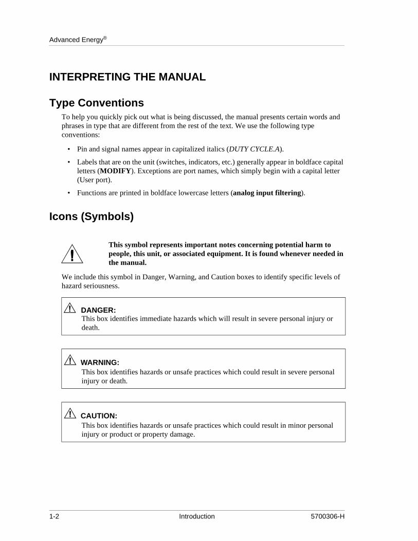
Type ConventionsTo help you quickly pick out what is being discussed, the manual presents certain words and phrases in type that are different from the rest of the text. We use the following type conventions:
• Pin and signal names appear in capitalized italics (DUTY CYCLE.A).
• Labels that are on the unit (switches, indicators, etc.) generally appear in boldface cletters (MODIFY). Exceptions are port names, which simply begin with a capital lett(User port).
• Functions are printed in boldface lowercase letters (analog input filtering).
Icons (Symbols)
This symbol represents important notes concerning potential harm to people, this unit, or associated equipment. It is found whenever needed in the manual.
We include this symbol in Danger, Warning, and Caution boxes to identify specific levelhazard seriousness.
DANGER:This box identifies immediate hazards which will result in severe personal injury odeath.
WARNING:This box identifies hazards or unsafe practices which could result in severe persoinjury or death.
CAUTION:This box identifies hazards or unsafe practices which could result in minor personinjury or product or property damage.
1-2 Introduction 5700306-H

MDX Sparc-le® 20
ning
The following symbols could appear on labels on your unit.
• Short circuit protected
• High voltage
• Protective earth ground
• Warning (refer to manual)
SAFETYDo not attempt to install or operate this equipment if you have not first acquired proper training.
• Make sure that this unit is properly grounded.
• Ensure that all cables are properly connected.
• Verify that input line voltage and current capacity are within specifications before turon the power supplies.
• Use proper ESD precautions.
• DO NOT BE CARELESS AROUND THIS EQUIPMENT.
WARNING:RISK OF DEATH OR BODILY INJURY. Disconnect all sources of input power before working on this unit or anything connected to it.
5700306-H Introduction 1-3
Advanced Energy®
INSTALLATION REQUIREMENTSOperating and maintenance personnel must receive proper training before installing or maintaining high-energy electrical equipment. Potentially lethal voltages could cause death, serious personal injury, or damage to the equipment. Ensure that all appropriate safety precautions are taken.
This unit requires the addition of a Protective Earth ground conductor on the rear panel and the use of a shielded power cable on the input terminal block.
1-4 Introduction 5700306-H
ChapterMDX Sparc-le® 20
Chapter
2
nal, arc than rc is
this
ve the A d
2Theory
General Description . . . . . . . . . . . . . . . . . . . . . . . . . . . . . . . . . . . . . . . . . . . . . . . . . . . . . . . . . . . . . . . 2-1Activation Counting . . . . . . . . . . . . . . . . . . . . . . . . . . . . . . . . . . . . . . . . . . . . . . . . . . . . . . . . . . . 2-1Supervisory Circuit . . . . . . . . . . . . . . . . . . . . . . . . . . . . . . . . . . . . . . . . . . . . . . . . . . . . . . . . . . . . 2-1
Theory of Operation . . . . . . . . . . . . . . . . . . . . . . . . . . . . . . . . . . . . . . . . . . . . . . . . . . . . . . . . . . . . . . . 2-1Active Arc-Handling Mode. . . . . . . . . . . . . . . . . . . . . . . . . . . . . . . . . . . . . . . . . . . . . . . . . . . . . . 2-2Self-Run Mode . . . . . . . . . . . . . . . . . . . . . . . . . . . . . . . . . . . . . . . . . . . . . . . . . . . . . . . . . . . . . . . 2-4Arc-Out Enhancement Mode . . . . . . . . . . . . . . . . . . . . . . . . . . . . . . . . . . . . . . . . . . . . . . . . . . . . 2-5
GENERAL DESCRIPTIONThe Sparc-le 20 (Small Package Arc Repression Circuit-Low Energy) 20 kHz unit is an add-on accessory for the Advanced Energy magnetron drive power supplies with output currents under 25 A. Its main function is to enhance the arc- handling capability of the MDX power supply. Even though the MDX power supplies exhibit excellent arc-handling characteristics (such as low output energy storage and recovery response time to hard arcs of under 10 ms), the demand for improved film quality with even fewer defects has arisen. This demand has led to the development of the Sparc-le 20 technology, which clears arcs in microseconds and dramatically reduces the number of hard arcs.
The Sparc-le 20 add-on accessory is a cost effective alternative to improving sputtered film quality. Its small size, coupled with minor modifications to the system cables, allows it to be easily retro-fitted into existing systems.
Activation CountingUsers have found that a knowledge of the arcing rate over the life of a target or over the duration of a process cycle can be used as a measure to explain defects or poor film quality. The Sparc-le 20 unit includes an isolated signal connected to a BNC connector which can be monitored by a counter. Each time a Sparc-le 20 unit suppresses an arc, a 5-V, 5-µs sigsuppression signal is generated. During heavy arcing, the pulse width may become less5 µs. During the self-run mode, the activation counter generates a signal only when an asuppressed between the pulses. That is, the self-run frequency cannot be monitored onoutput.
Supervisory CircuitAn internal supervisory circuit within the Sparc-le 20 unit monitors its function in the actiarc-handling and self-run modes. The purpose of this circuit is to notify the operator thatSparc-le 20 unit is not functioning properly; this prevents yield loss in critical processes.signal is produced at the Sparc-le 20 User port in the case of a unit malfunction. The loacurrent must exceed 1.5 A before the supervisory circuit becomes operational.
5700306-H Theory 2-1

Advanced Energy®
n ent ched
THEORY OF OPERATIONThe Sparc-le 20 unit is inserted between the MDX power supply and the chamber, see Figure 2-1 . It is connected in series with the output of the MDX power supply and physically located close to the chamber. The Sparc-le 20 circuitry responds to arcs within microseconds and therefore requires that the impedance (distance) between it and the chamber be kept to a minimum.
.
Figure 2-1. Physical location of Sparc-le 20 in a system
The Sparc-le 20 unit’s arc-handling current characteristic immediately shunts the target current away from the target and starves the arc. By removing the current source and, for a short time, reversing the target voltage, the arcs are quenched quickly.
The Sparc-le 20 has three operating modes:
• Active Arc-handling mode
• Self-run mode
• Arc-Out enhancement mode
Active Arc-Handling ModeThe active arc-handling mode is the primary operating mode of Sparc-le 20 unit. You caselect this mode from the front panel or the User port. In this mode, the target current isimmediately shunted away from the target when an arc is about to begin. When the currsource is removed and the target voltage is reversed for a short time, the arcs are quenquickly.
2-2 Theory 5700306-H

MDX Sparc-le® 20
other unit. In
er and
the w far d to
rigger
An illustration of the Sparc-le 20 unit’s arc-handling characteristics in the active arc-handling mode is shown in Figure 2-2and Figure 2-3. Arcs can be handled at a rate of up to 40,000 arcs per second. If this rate is continuously exceeded, the unit overheats and automatically switch over to the arc-out enhancement circuit for target cleaning. After clearing the arc, the Sparc-le 20 unit requires at least 10 µs for the internal pulse transformer core to reset. Should anarc occur before this 10 µs has elapsed, this arc might not be cleared by the Sparc-le 20this case, the arc may become a hard arc and draw excessive current until the MDX powsupply turns off. After the MDX supply clears the hard arc, it automatically turns back onthe process continues.
Prior to an arc occurring, the target voltage collapses on most chambers. That is, while system is operating at a negative potential, voltage drops sharply towards zero volts. Hothe target voltage collapses depends upon the target material. Higher impedance targetmaterials tend not to drop as far as lower impedance targets. This voltage change is usetrigger the Sparc-le 20 unit into action. The Sparc-le 20 unit uses an automatic tracking tcircuit which allows the user to operate over the entire output voltage range without adjustment.
Figure 2-2. Target voltage during active arc-handling mode
5700306-H Theory 2-3

Advanced Energy®
s oxide o mode.
This rs.
power o start.
e target al e way,
Sparc-c-out e ncy”
Figure 2-3. Target current during active arc-handling mode
Self-Run ModeYou can select this mode through the Sparc-le 20 front panel or User port. When selected, the Sparc-le 20 unit shorts out and reverses the target voltage for 5 µs at a 20-kHz rate. Thireversal of voltage prevents charge buildup on the system surfaces, slows the growth offilms, and extends target life. During this self-run mode, the Sparc-le 20 unit continues tprocess arcs as they occur (up to a 40 kHz rate). This is also what happens in active arc
At operation above 700 V, the internal self-run frequency automatically shifts to 15 kHz. lower self-run frequency is required to lower the power dissipation in the snubber resisto
The self-run mode selection engages a 20-kHz oscillator which triggers the Sparc-le 20 switches. This action produces the same output characteristics as if an arc were about tThe only difference is that the activation effect is created internally by the Sparc-le 20 switches and not by an arc in the chamber. The Sparc-le 20 switches first discharge thechamber capacitance and then reverse the chamber voltage. This voltage reversal on thprevents charge buildup on the system surfaces and slows insulating film build-up. Normarcs, which may occur while the self-run mode has been selected, are processed the samat a maximum rate of 20,000 arcs per second. The self-run mode can only operate whenle 20 unit has been turned on or enabled. It will not function if Sparc-le 20 unit is in the arenhancement mode.The self-run mode frequency of 20 kHz can be changed to match thoriginal Sparc-le unit's self-run mode frequency of 2 kHz. See “Changing Self-run Frequeon page 5-2.
2-4 Theory 5700306-H

MDX Sparc-le® 20
20 µs.
cing ng AE's e
t
Figure 2-4. Target voltage during self-run mode
Figure 2-5. Target current during self-run mode
Arc-Out Enhancement ModeThe arc-out enhancement mode is active when the Sparc-le 20 unit is turned off or not enabled. The arc-out circuit consists of passive components and clamp rectifiers only. During an arc, it functions as a resonant LC network which discharges and then commutates off the arc through its reversing action. This process is also very fast, and arcs can be suppressed in underThe target voltage and current for this mode are shown in Figure 2-6 and Figure 2-7.
For certain target materials, some arc energy is required to initially clean the target of arsites. In these cases, the Sparc-le 20 unit is so effective in lowering arc energy that a loperiod is necessary for new target conditioning. Also, experience has shown that when new arc-out enhancement circuit is used, the target is cleaned more quickly than with thstandard MDX supply alone. The Sparc-le 20 design anticipates its use with older MDX models not having this new feature and therefore includes the new arc-out enhancemencircuitry. When the Sparc-le 20 is turned off, it automatically switches in the arc-out enhancement circuit.
5700306-H Theory 2-5

Advanced Energy®
Figure 2-6. Target voltage during arc-out enhancement mode
Figure 2-7. Target current during arc-out enhancement mode
2-6 Theory 5700306-H

ChapterMDX Sparc-le® 20
Chapter
3
3Specifications
Functional Specifications . . . . . . . . . . . . . . . . . . . . . . . . . . . . . . . . . . . . . . . . . . . . . . . . . . . . . . . . . . . 3-1Physical Specifications. . . . . . . . . . . . . . . . . . . . . . . . . . . . . . . . . . . . . . . . . . . . . . . . . . . . . . . . . . . . . 3-2Electrical Specifications . . . . . . . . . . . . . . . . . . . . . . . . . . . . . . . . . . . . . . . . . . . . . . . . . . . . . . . . . . . . 3-2Environmental Specifications. . . . . . . . . . . . . . . . . . . . . . . . . . . . . . . . . . . . . . . . . . . . . . . . . . . . . . . . 3-3
FUNCTIONAL SPECIFICATIONSThe following table lists the functional specifications.
Table 3-1. Functional Specifications
Control Signal Source MDX User Port
Fault Conditions An overtemperature condition causes the Sparc-le 20 unit to cease functioning in its active arc-handling mode. It automatically switches to the ARC-OUT enhancement mode. An overtemperature condition is indicated by the OVERTEMP LED on the front panel.
An over-voltage condition (input voltage to the Sparc-le 20 unit exceeds 1000 V) prevents the Sparc-le 20 unit from operation in its active arc-handling mode. It automatically switches to the ARC-OUT enhancement mode. When the input voltage drops below 1000 V, the Sparc-le 20 unit switches back automatically to the prior arc-handling mode. and over-voltage condition is reported as a low out-put on pin 7 of the Sparc-le 20 User port.
An open signal on pin 9 of the User port means a loss of ac power to the Sparc-le 20 unit, or an overtemperature con-dition, or an open interlock switch.
5700306-H Specifications 3-1

Advanced Energy®
PHYSICAL SPECIFICATIONSThe following table lists the physical specifications.
ELECTRICAL SPECIFICATIONSThe following table lists the electrical specifications.
Table 3-2. Physical Specifications
DC Input and Output Connectors
UHF type, female, Amphenol part number 83-1R Optional: 2-position terminal block or MS-3470 connec-tors (male for input, female for output)
Cable Connector for DC Input and Output
UHF type, male, Amphenol part number 83-822Optional: terminal block or MS-3476 connector
DC Input and Output Cables
RG-8U coaxial cable; output cable from Sparc-le 20 to chamber not to exceed 6 m (20 ft.)
Size 13.3 cm x 48.3 cm x 19.4 cm(5.25" (H) x 19"(W) x 7.65" (D))
Weight 7.7 kg (17 lb) maximum
WARNING:Positive voltage output with a negative ground is prohibited. Hardware damage will occur.
Table 3-3. Electrical Specifications
AC Input Voltage 90 to 126.5 V ac rms, 50/60 Hz, single phase, 30 VA 180 to 253 V ac rms, 50/60 Hz, single phase, 30 VA
DC Input Voltage Any low-Z or standard-Z output from an MDX magnetron supply
DC Current 25 A steady state maximum. No minimum current is required for operation. The supervisory circuit requires a minimum of 1.5 A before it is operational.
Note: Low power Sparc-le 20 units should be operated only up to 3 A. If you are unsure whether you have a low power Sparc-le 20 unit, please note the part number on the unit (315xxxx-xxx) and contact AE.
Input and Output DC Polarity
Negative output (positive at ground);Negative output (positive floating less than 100 V from ground)
3-2 Specifications 5700306-H
MDX Sparc-le® 20
f
rti-
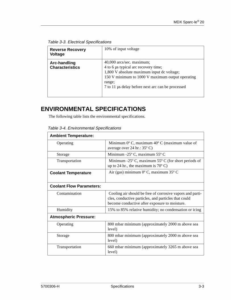
ENVIRONMENTAL SPECIFICATIONS The following table lists the environmental specifications.
Reverse Recovery Voltage
10% of input voltage
Arc-handling Characteristics
40,000 arcs/sec. maximum;4 to 6 µs typical arc recovery time;1,800 V absolute maximum input dc voltage;150 V minimum to 1000 V maximum output operating range;7 to 11 µs delay before next arc can be processed
Table 3-3. Electrical Specifications
Table 3-4. Environmental Specifications
Ambient Temperature:
Operating Minimum 0º C, maximum 40º C (maximum value of average over 24 hr.: 35º C)
Storage Minimum -25º C, maximum 55º C
Transportation Minimum -25º C, maximum 55º C (for short periods oup to 24 hr., the maximum is 70º C)
Coolant Temperature Air (gas) minimum 0º C, maximum 35º C
Coolant Flow Parameters:
Contamination Cooling air should be free of corrosive vapors and pacles, conductive particles, and particles that could become conductive after exposure to moisture.
Humidity 15% to 85% relative humidity; no condensation or icing
Atmospheric Pressure:
Operating 800 mbar minimum (approximately 2000 m above sealevel)
Storage 800 mbar minimum (approximately 2000 m above sealevel)
Transportation 660 mbar minimum (approximately 3265 m above sealevel)
5700306-H Specifications 3-3

Advanced Energy®
3-4 Specifications 5700306-H

ChapterMDX Sparc-le® 20
Chapter
4
4Connectors, Indicators and Controls
Connectors . . . . . . . . . . . . . . . . . . . . . . . . . . . . . . . . . . . . . . . . . . . . . . . . . . . . . . . . . . . . . . . . . . . . . . 4-1Input AC Power Connector . . . . . . . . . . . . . . . . . . . . . . . . . . . . . . . . . . . . . . . . . . . . . . . . . . . . . . 4-1Input DC Power Connector . . . . . . . . . . . . . . . . . . . . . . . . . . . . . . . . . . . . . . . . . . . . . . . . . . . . . . 4-1Output DC Power Connector . . . . . . . . . . . . . . . . . . . . . . . . . . . . . . . . . . . . . . . . . . . . . . . . . . . . 4-2Terminal Block Connectors (Optional). . . . . . . . . . . . . . . . . . . . . . . . . . . . . . . . . . . . . . . . . . . . . 4-2Military Style Connectors (Optional) . . . . . . . . . . . . . . . . . . . . . . . . . . . . . . . . . . . . . . . . . . . . . . 4-3Remote Control Panel Connector . . . . . . . . . . . . . . . . . . . . . . . . . . . . . . . . . . . . . . . . . . . . . . . . . 4-5BNC, Activation-counting Port. . . . . . . . . . . . . . . . . . . . . . . . . . . . . . . . . . . . . . . . . . . . . . . . . . . 4-5User Analog/Digital I/O Port . . . . . . . . . . . . . . . . . . . . . . . . . . . . . . . . . . . . . . . . . . . . . . . . . . . . 4-5User Port Pin Descriptions . . . . . . . . . . . . . . . . . . . . . . . . . . . . . . . . . . . . . . . . . . . . . . . . . . . . . . 4-6
Indicators . . . . . . . . . . . . . . . . . . . . . . . . . . . . . . . . . . . . . . . . . . . . . . . . . . . . . . . . . . . . . . . . . . . . . . . 4-7Status Signals . . . . . . . . . . . . . . . . . . . . . . . . . . . . . . . . . . . . . . . . . . . . . . . . . . . . . . . . . . . . . . . . 4-7Front Panel Indicators . . . . . . . . . . . . . . . . . . . . . . . . . . . . . . . . . . . . . . . . . . . . . . . . . . . . . . . . . . 4-7
Unit Illustrations. . . . . . . . . . . . . . . . . . . . . . . . . . . . . . . . . . . . . . . . . . . . . . . . . . . . . . . . . . . . . . . . . . 4-8Front View of the Sparc-le 20 . . . . . . . . . . . . . . . . . . . . . . . . . . . . . . . . . . . . . . . . . . . . . . . . . . . . 4-8Rear View of Sparc-le 20 . . . . . . . . . . . . . . . . . . . . . . . . . . . . . . . . . . . . . . . . . . . . . . . . . . . . . . . 4-9Rear View of Sparc-le 20 (MS-3470 Connectors) . . . . . . . . . . . . . . . . . . . . . . . . . . . . . . . . . . . 4-10Rear View of Sparc-le 20 (Terminal Block) . . . . . . . . . . . . . . . . . . . . . . . . . . . . . . . . . . . . . . . . 4-11Dimensions . . . . . . . . . . . . . . . . . . . . . . . . . . . . . . . . . . . . . . . . . . . . . . . . . . . . . . . . . . . . . . . . . 4-12
CONNECTORS
Input AC Power ConnectorEach Sparc-le 20 unit is supplied with its own ac line cord. Depending upon the model ordered, there is either a line cord with a U.S. 115 V ac three-prong plug or a line cord with a German two-prong plug for 220 V ac operation. Each unit is wired to accept the line voltages associated with the line cord provided.
See “Connecting AC Input Power” on page 5-4 for installation information.
5700306-H Connectors, Indicators and Controls 4-1

Advanced Energy®
that has DX
e unit 0 on
the nd
Input DC Power ConnectorThe output of the MDX magnetron power supply becomes the input dc to the Sparc-le 20 unit. The standard input dc connector to the Sparc-le 20 unit is a UHF male connector (Amphenol 83-822). A 2-position terminal block or MS-3470 connector is optional on the Sparc-le 20 unit ( see “Military Style Connectors (Optional)” on page 4-3).
With units featuring the standard UHF dc input connector, an assembled 6-foot cable, connectors, and insulating sleeves are provided at the time of purchase. The cable end the long insulating sleeve over the UHF connector is intended to be connected to the Moutput.
See “Connecting the DC Input and Output” on page 5-4 for more information.
Output DC Power ConnectorThe standard output dc power connector is the same type of male UHF connector with insulating sleeve as is used for the input. This connector and sleeve are provided with that the time of purchase; the cable is not provided. A 2-position terminal block or MS-347connector is optional on the Sparc-le 20 unit ( see “Military Style Connectors (Optional)”page 4-3).
See “Connecting the DC Input and Output” on page 5-4 for installation information.
Figure 4-1. Standard UHF-type dc input and output connector
WARNING:Ensure that the input dc power connector is connected to the Sparc-le 20 input connector labeled “MDX” and that the output dc power connector is connected to Sparc-le 20 output connector labeled “CHAMBER”. Also ensure that you maintainproper polarity when making these connections. Failure to correctly connect input aoutput power could result in damage to the unit.
4-2 Connectors, Indicators and Controls 5700306-H

MDX Sparc-le® 20
r is a ctor me for
ting o
Terminal Block Connectors (Optional)A 2-position terminal block connector is optional on the Sparc-le 20 (Figure 4-2). See “Connecting the DC Input and Output” on page 5-4 for installation information.
Figure 4-2. Optional terminal block connector for dc input and output
Military Style Connectors (Optional)Military style connectors are optional on the Sparc-le 20. The MS-3470 dc input connectomale MS3470 connector; the MS-3470 dc output connector is a female MS-3470 conne(See Figure 4-3). The pin descriptions, described in Table 4-1 and Table 4-2, are the saboth the input and output.
The full military specification numbers for these connectors are MS3470-L18-8P and MS3470-L18-8S, respectively. Recall that cabling and other attached components (a maconnector, for example) for these connectors also have military specification numbers. Tconfigure and/or assemble connecting components, refer to the appropriate military specifications. AE does not supply mating connectors.
See “Connecting the DC Input and Output” on page 5-4 for installation information.
Figure 4-3. Optional MS-3470 connector
5700306-H Connectors, Indicators and Controls 4-3

Advanced Energy®
Pin Descriptions for Male ConnectorThe following table lists the pin descriptions for the male connector:
Pin Descriptions for Female ConnectorThe following table lists the pin descriptions for the female connector:
Table 4-1. Pin Descriptions for Male Connector
Pin Letter Description
A Unused; do not connect
B Positive return (to dc supply)
C Ground
D Interlock
E Interlock
F Ground
G Unused; do not connect
H Negative supply (from dc supply)
Table 4-2. Pin Descriptions for Female Connector
Pin Letter Description
A Unused; do not connect
B Positive return (from chamber)
C Ground
D Interlock
E Interlock
F Ground
G Unused; do not connect
H Negative supply (to chamber)
4-4 Connectors, Indicators and Controls 5700306-H
MDX Sparc-le® 20
ivated
Remote Control Panel ConnectorConnections for remote control of the Sparc-le 20 unit can be made through a 9-pin, female, D subminiature connector. This female connector and housing are provided with the unit at the time of purchase.
BNC, Activation-counting PortA BNC connector, referenced to chassis ground, is provided and available to be connected to an external counter. A 5-V, 5-µs pulse is generated each time the Sparc-le 20 unit is actto repress an arc. This pulse width is less when the unit is experiencing an over-currentcondition. The self-run frequency is not present at this output.
User Analog/Digital I/O PortThe table below provides information about each pin on the User port connector. See “Connecting AC Input Power” on page 5-4 for details on making this connection.
The User connector is primarily an “analog” interface that allows the use of a remote controller.
5700306-H Connectors, Indicators and Controls 4-5

Advanced Energy®
pin ignal
o
t
r
y
t,
User Port Pin DescriptionsThe following table provides information about each pin in the User port connector.
Note: A “.A” appended to a pin name indicates an analog signal; a “.D” appended to thename indicates a digital signal. An overline on the signal name indicates that the sis true when low.
Table 4-3. User Port Pin Descriptions
Pin Name Description
pin 1 OUTCOM.D This is a dedicated return line to the MDX. It is connectedto chassis ground and then to protective earth-ground atthe MDX.
pin 2 +15 VDC This is a voltage which must be applied to Sparc-le 20'sinterface circuits. A capability of 50 mA is required.
pin 3 ENABLE.D This 15 Vdc signal must be pulled low to activate Sparc-le 20's active arc-handling mode. The user must be able tsink 20mA from this pin
pin 4 SELFRUN.D This 15 Vdc signal must be pulled low to activate Sparc-le 20's self-run mode. The user must be able to sink 20 mA from this pin
pin 5 INTCOM.A This signal connects to the internal Sparc-le 20 ground. Iis active on pin 5 only when S1 on the Sparc-le 20's logic board has been activated.
pin 6 SUPERVC.D This collector is normally connected to +15 VDC (pin2) through switch S2-1 being closed on Sparc-le 20 logic board. (For more information about logic board switches,see page 3-5.)
pin 7 SUPERVE.D This signal is low or open during a fault of Sparc-le 20'sactive arc-handling mode. This also shows a fault when the input dc voltage to Sparc-le 20 is too low or too high to operate while in the active arc-handling mode. This pinwill sink up to 2 mA.
pin 8 +15VDCINT This signal connects to the internal 15 V dc used to poweSparc-le 20's logic circuits. It is active only when S1 on the Sparc-le20 logic board has been activated. It can onlsource 50 mA.
pin 9 OVERTEMP/AC PWR/INTERLOCK.D
This 0-15 V dc signal opens whenever an overtemperature trip has occurred in the Sparc-le 20 uniwhenever the ac line cord has been disconnected, or whenever an interlock switch is open. This pin will sink up to 2 mA maximum.
4-6 Connectors, Indicators and Controls 5700306-H

MDX Sparc-le® 20
INDICATORS
Status SignalsStatus signals can be externally monitored by means of an output line on the User port. Digital signals are 0 to 15 V.
Front Panel IndicatorsThere are seven LED indicators on the Sparc-le 20 front panel. See the panel drawings at the end of this chapter for LED locations. The table below provides details.
Table 4-4. Status Signals
Pin Name Function
9 OVERTEMP/AC PWR/INTERLOCK.D
Opens when overtemperature condition or loss of ac power occurs
7 SUPERVE.D Opens when the active arc-handling function is not operating properly
Table 4-5. Front Panel Indicators
LED Name Function
Power On/ready Green LED; lights to indicate that power is on
Mode Override (Overvoltage/overtemp)
Yellow LED; lights to indicate an internal overtem-perature or over-voltage condition. The operating mode is automatically switched to ARC-OUT enhancement mode. When the fault condition clears, Sparc-le20 automatically switches back to the prior operating mode, and this LED goes out.
Active Arc Green LED; lights to indicate that active arc-han-dling mode has been selected with the OPERAT-ING MODE switch
Self Run Green LED; lights to indicate that self-run mode has been selected with the OPERATING MODE switch
Local Green LED; lights to indicate local control-from the Sparc-le20 unit’s front panel
Remote Green LED; lights to indicate remote control-from the Sparc-le20 unit’s User port
5700306-H Connectors, Indicators and Controls 4-7

Advanced Energy®
UNIT ILLUSTRATIONS
Front View of the Sparc-le 20
Figure 4-4. Front View of the Sparc-le 20
4-8 Connectors, Indicators and Controls 5700306-H
MDX Sparc-le® 20
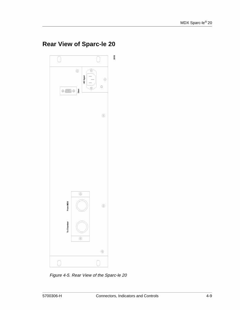
Rear View of Sparc-le 20
Figure 4-5. Rear View of the Sparc-le 20
5700306-H Connectors, Indicators and Controls 4-9

Advanced Energy®
Rear View of Sparc-le 20 (MS-3470 Connectors)
Figure 4-6. Rear View of the Sparc-le 20 with military style connectors
4-10 Connectors, Indicators and Controls 5700306-H
MDX Sparc-le® 20
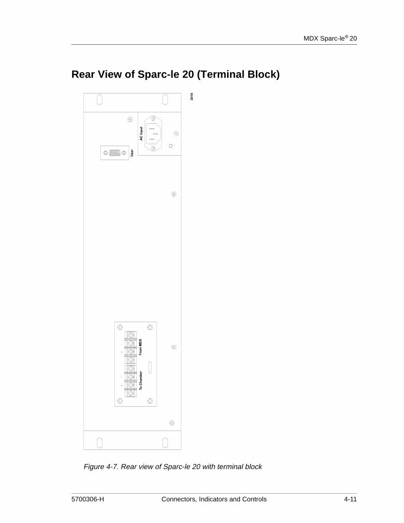
Rear View of Sparc-le 20 (Terminal Block)
Figure 4-7. Rear view of Sparc-le 20 with terminal block
5700306-H Connectors, Indicators and Controls 4-11
Advanced Energy®
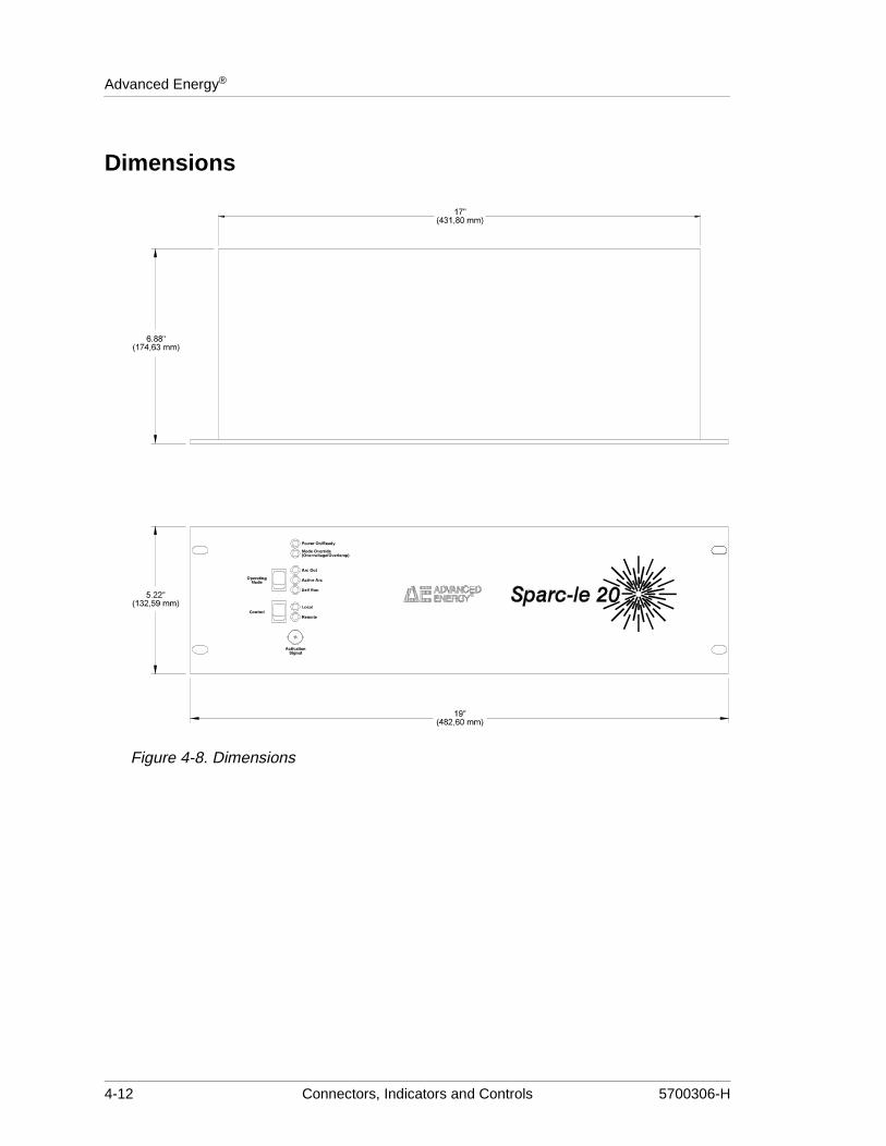
Dimensions
Figure 4-8. Dimensions
4-12 Connectors, Indicators and Controls 5700306-H

ChapterMDX Sparc-le® 20
Chapter
5
lets
5Installation
Setting Up. . . . . . . . . . . . . . . . . . . . . . . . . . . . . . . . . . . . . . . . . . . . . . . . . . . . . . . . . . . . . . . . . . . . . . . 5-1Unpacking . . . . . . . . . . . . . . . . . . . . . . . . . . . . . . . . . . . . . . . . . . . . . . . . . . . . . . . . . . . . . . . . . . . 5-1Design Considerations. . . . . . . . . . . . . . . . . . . . . . . . . . . . . . . . . . . . . . . . . . . . . . . . . . . . . . . . . . 5-1Cooling Requirements. . . . . . . . . . . . . . . . . . . . . . . . . . . . . . . . . . . . . . . . . . . . . . . . . . . . . . . . . . 5-1Logic Board Switches . . . . . . . . . . . . . . . . . . . . . . . . . . . . . . . . . . . . . . . . . . . . . . . . . . . . . . . . . . 5-1Changing Self-run Frequency . . . . . . . . . . . . . . . . . . . . . . . . . . . . . . . . . . . . . . . . . . . . . . . . . . . . 5-2Using the Interlock Switch Option . . . . . . . . . . . . . . . . . . . . . . . . . . . . . . . . . . . . . . . . . . . . . . . . 5-2
Making Rear Panel Connections . . . . . . . . . . . . . . . . . . . . . . . . . . . . . . . . . . . . . . . . . . . . . . . . . . . . . 5-2Grounding . . . . . . . . . . . . . . . . . . . . . . . . . . . . . . . . . . . . . . . . . . . . . . . . . . . . . . . . . . . . . . . . . . . 5-3Connecting AC Input Power . . . . . . . . . . . . . . . . . . . . . . . . . . . . . . . . . . . . . . . . . . . . . . . . . . . . . 5-3Connecting the DC Input and Output . . . . . . . . . . . . . . . . . . . . . . . . . . . . . . . . . . . . . . . . . . . . . . 5-3
Connecting to the Terminal Block . . . . . . . . . . . . . . . . . . . . . . . . . . . . . . . . . . . . . . . . . . . . . 5-3Connecting to the MS-3470 Connectors . . . . . . . . . . . . . . . . . . . . . . . . . . . . . . . . . . . . . . . . 5-4
SETTING UP
UnpackingUnpack and inspect your MDX Sparc-le 20 accessory carefully. Check for obvious physical damage. If no damage is apparent, proceed to make the connections. If you do see signs of shipping damage, contact Advanced Energy Industries, Inc., and the carrier immediately. Save the shipping container for submitting necessary claims to the carrier.
Design ConsiderationsThe Sparc-le 20 technology performs best when it is physically located within 6 m (20 ft) of cable distance from the chamber cathode. The Sparc-le 20 unit is made to bolt into either the front or rear of a rack. Cooling of the Sparc-le 20 unit is provided by an internal fan. Take precautions when mounting the unit to prevent its air flow from being restricted.
Cooling RequirementsThe Sparc-le 20 unit contains its own internal fan for cooling. When you install a Sparc-le 20 unit on your system, ensure that it is in a location where its maximum ambient temperature is not exceeded (see “Environmental Specifications” on page 3-3) and where its air vent inand outlets are not obstructed.
5700306-H Installation 5-1

Advanced Energy®
Logic Board Switches
Note: Before removing the Sparc-le 20 unit cover, take proper precautions against ESD (Electro-static discharge). Potential damage to the unit could occur.
To set the switches discussed in the following sections, you must access the logic board by removing the unit cover. Before removing the unit cover, remove ac and dc input power from the Sparc-le 20 unit, take proper precautions against ESD (electro-static discharge), and take care to remove all unit cover screws. If you are uncertain about this procedure, please contact the nearest AE Customer Service office.
Changing Self-run FrequencyA switch on the logic board has been provided so that you can change the self-run frequency from 20 kHz to 2 kHz. Units shipped from the factory always have this switch set in the 20 kHz position. The self-run frequency can be changed via an access port located at the rear of the unit.
DANGER:Before removing the Sparc-le 20 unit cover, take proper precautions against ESD (electro-static discharge). Potential damage to the unit could occur.
CAUTION:Do not change the frequency setting while the unit is operating. Turn off the DC supply and unplug the SPARC-LE 20 line cord before changing the frequency setting.
5-2 Installation 5700306-H

MDX Sparc-le® 20
Change the frequency by using a small screwdriver to rotate the frequency control switch located at the rear of the unit. The slot in the rotary switch is vertical for 20 kHz operation or horizontal for to 2 kHz operation. Do not rotate the switch past the 20 kHz or 2 Khz position as shown in Figure 5-1. Only the self-run frequency is affected; the rate at which arcs are handled remains the same.
Figure 5-1. Frequency change switch
Using the Interlock Switch OptionThe cover over the input and output connectors engages an interlock switch. This switch is bypassed on units shipped from the factory by switch S2-2 on the logic board. This allows the Sparc-le 20 unit to be evaluated without the User port functions. When you are ready to take advantage of the User port functions and the interlock switch, open switch S2-2. (The interlock switch is not applicable with the MS-3470 units.)
MAKING REAR PANEL CONNECTIONS
GroundingA protective earth terminal stud is located next to the input ac line cord connector. This terminal is connected internally to the input line cord ground wire at the ac line cord connector.
Note: For optimum performance, ground the chassis stud to the chamber ground.
DANGER:Connect the protective earth terminal on the MDX rear panel to protective earth-ground before making any other connection.
5700306-H Installation 5-3
Advanced Energy®
ode,
parc-ns are The an be
r (see for
tput.
cover
ntain
or
Connecting AC Input PowerThe ac input line connection is made through a line cord possessing either a standard US three-prong 115 V ac type or a two-prong German 220 V ac type plug. When a unit is purchased, it is internally connected for the correct line voltage at the factory and then supplied with the appropriate line cord. A sticker located next to the line cord connector indicates the voltage for which the unit has been wired. The range of input line voltages for each case and the associated line cord plug are listed below.
• U.S. 115 V ac plug: 90-126.5 V ac rms, 50/60 Hz, single phase, 30VA
• German plug: 180-253 V ac rms 50/60 Hz, single phase, 30 VA
It is important to note that for the Sparc-le 20 unit to operate in its active arc-handling mac input power must be present. Operation of the system with the Sparc-le 20 line cord unplugged restricts it to Arc Out enhancement mode operation only.
Connecting the DC Input and OutputA female UHF-type connector is standard for both the dc input and output on the MDX Sle 20 unit (see Figure 4-1 on page 4-2). As a result, both the input and output connectiomade by means of a male UHF-type connector (Amphenol 83-822), which AE provides.RG-8U cables for both input and output are not included with the Sparc-le 20 unit, but cpurchased from AE separately.
An optional terminal block connector (see Figure 4-2 on page 4-3) or MS-3470 connectoFigure 4-3 on page 4-3) are available for dc input and output. See the following section instructions on connecting to these types of connector
CONNECTING TO THE TERMINAL BLOCKThe optional terminal block connector features two positions each for dc input and dc ouTo connect to the terminal block, follow these steps.
1. Ensure that ac input power has been removed from the Sparc-le 20 unit.
2. Power off the MDX power supply.
3. Remove the connector cover from the rear of the Sparc-le 20 unit.
4. Slide the appropriate cables up through the two holes in the bottom of the connectorand out the back of the cover (see Figure 5-2 on page 5-5).
5. Attach the cables to the appropriate positions on the connector, taking care to maiproper polarity.
6. Re-attach the connector cover (see Figure 5-2 on page 5-5).
Note: The connector cover features a metal tongue that slides into a slot on the connectplate. Inserting this tongue into the slot provides interlock when switch S2-2 is open. (For more information about the interlock switch, see “Using the Interlock Switch Option” on page 5-3.)
5-4 Installation 5700306-H

MDX Sparc-le® 20
Figure 5-2. Connecting dc input and output to the terminal block
CONNECTING TO THE MS-3470 CONNECTORSTo connect the optional military style connector to the terminal block, follow these steps.
1. Ensure that ac input power has been removed from the Sparc-le 20 unit.
2. Power off the MDX power supply.
3. Attach the cables to the appropriate connectors.
5700306-H Installation 5-5

Advanced Energy®
5-6 Installation 5700306-H
ChapterMDX Sparc-le® 20
Chapter
6
6Operation
Methods of Control. . . . . . . . . . . . . . . . . . . . . . . . . . . . . . . . . . . . . . . . . . . . . . . . . . . . . . . . . . . . . . . . 6-1Front Panel (Manual) Control . . . . . . . . . . . . . . . . . . . . . . . . . . . . . . . . . . . . . . . . . . . . . . . . . . . . 6-1User Port Control . . . . . . . . . . . . . . . . . . . . . . . . . . . . . . . . . . . . . . . . . . . . . . . . . . . . . . . . . . . . . 6-1
Supervisory Circuit . . . . . . . . . . . . . . . . . . . . . . . . . . . . . . . . . . . . . . . . . . . . . . . . . . . . . . . . 6-3Factory Configuration . . . . . . . . . . . . . . . . . . . . . . . . . . . . . . . . . . . . . . . . . . . . . . . . . . . . . . 6-3
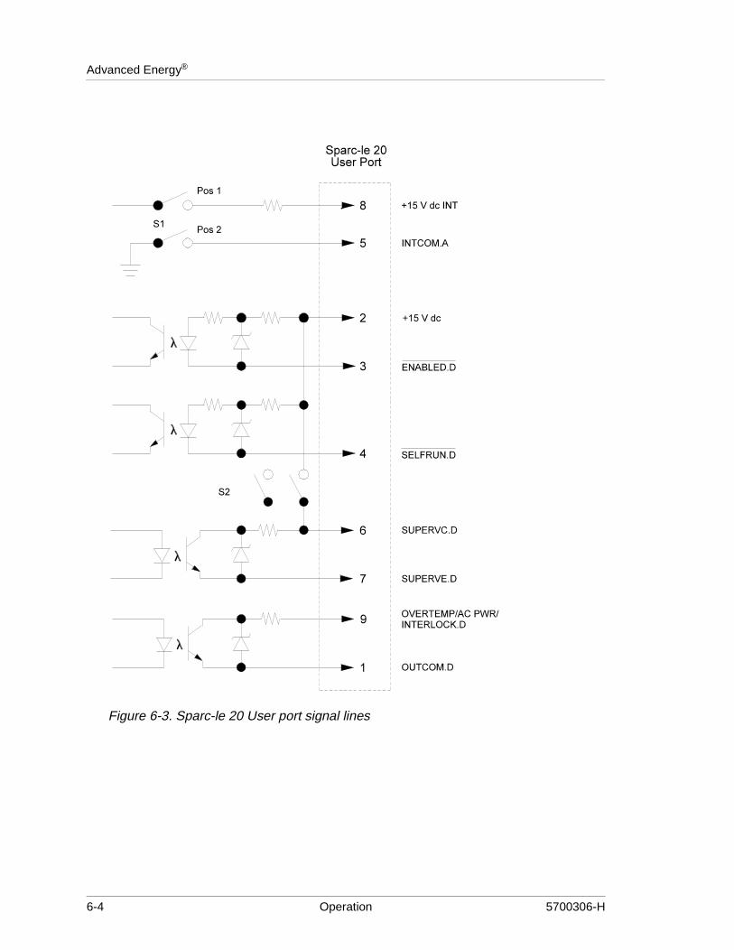
METHODS OF CONTROLYou can control the Sparc-le 20 unit from the front panel switches or from the User port through optically coupled signals. The interfacing functions available on the Sparc-le 20 unit are represented by the abbreviated schematic (Figure 6-3 on page 6-4). Units are shipped from the factory configured for User port control.
Front Panel (Manual) ControlA Sparc-le 20 unit can be controlled manually from the front panel. Select LOCAL with the two-position CONTROL switch. Then use the three-position OPERATING MODE switch to select an operating mode. Although the manual method of operation limits the available options, it does allow the unit to be quickly evaluated on a system without adding additional control cables.
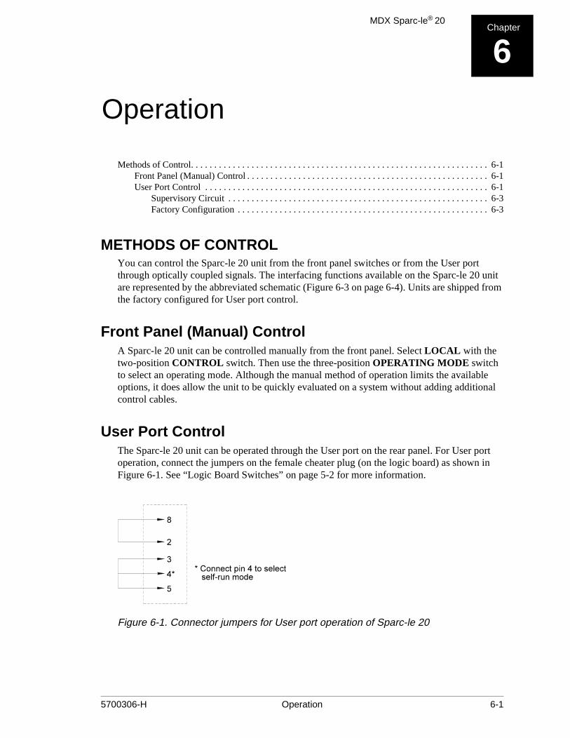
User Port ControlThe Sparc-le 20 unit can be operated through the User port on the rear panel. For User port operation, connect the jumpers on the female cheater plug (on the logic board) as shown in Figure 6-1. See “Logic Board Switches” on page 5-2 for more information.
Figure 6-1. Connector jumpers for User port operation of Sparc-le 20
5700306-H Operation 6-1

Advanced Energy®
the ater d, rc-le ted at
n a de
The User interface connector is a 9-pin, male, subminiature-D connector located on the rear panel. Details of each of these signals and their function are described in “User Port PinDescriptions” on page 4-6.
The Sparc-le 20 unit can also be operated through the MDX User port. Both switches onS1 switch assembly must be open and no jumpers should be installed in the female cheplug for MDX control. (For more information about setting the switches on the logic boar“Logic Board Switches” on page 5-2.) The control lines used on the MDX to control Spa20 unit are illustrated in Figure 6-2. As can be seen from Figure 6-2, when CS2.D is selecthe MDX, then Sparc-le 20 unit is activated. The Sparc-le 20 self-run mode is selected isimilar manner using the MDX unit's CS1.D line. When using the MDX to control a cathoswitch box, another means is required to control Sparc-le 20.
Figure 6-2. MDX User port control of Sparc-le 20
6-2 Operation 5700306-H

MDX Sparc-le® 20
the
The following chart illustrates how the three operating modes of the Sparc-le 20 unit can be selected using the MDX User port functions and the Sparc-le 20 User port.
SUPERVISORY CIRCUITAn internal supervisory circuit within the Sparc-le 20 unit monitors its function in the active arc-handling and self-run modes. The purpose of this error signal (User pin 7, SUPERVE.D) is to notify the operator that Sparc-le 20 is not functioning properly. This signal is intended to be handled independently of the MDX User port, preferably by the system controller. This is because the decision as to whether or not to shut off the MDX should be made at the system level. Switch assembly S2-1, located on Sparc-le 20’s logic board, must be in its closed position to make the fault signal low on Sparc-le 20’s User pin 7 (Figure 6-3 on page 6-4). “Logic Board Switches” on page 5-2 for more information about setting the switches on logic board.
Note: You need to supply a 5 kW pull-down resistor for User pin 7.
Load current must exceed 1.5 A before the supervisory circuit becomes functional.
FACTORY CONFIGURATIONWhen Sparc-le 20 is shipped, positions 1 and 2 on switch S1 are set OPEN, and positions 1 and 2 on switch S2 are set CLOSED. The self-run frequency is set to 20 kHz.
Table 6-1. Operating Modes
Target CS1.D CS2.D Sparc-le 20 operating mode
1 Low High arc-out enhancement
2 High Low active arc handling
3 Low Low self run
5700306-H Operation 6-3
Advanced Energy®
Figure 6-3. Sparc-le 20 User port signal lines
6-4 Operation 5700306-H
ChapterMDX Sparc-le® 20
Chapter
7
ied to
7Troubleshooting and Customer Support
Before Calling AE Customer Support . . . . . . . . . . . . . . . . . . . . . . . . . . . . . . . . . . . . . . . . . . . . . . . . . 7-1Checks with the Power Off . . . . . . . . . . . . . . . . . . . . . . . . . . . . . . . . . . . . . . . . . . . . . . . . . . . . . . 7-1Checks with the Power On . . . . . . . . . . . . . . . . . . . . . . . . . . . . . . . . . . . . . . . . . . . . . . . . . . . . . . 7-1
Returning Units for Repair . . . . . . . . . . . . . . . . . . . . . . . . . . . . . . . . . . . . . . . . . . . . . . . . . . . . . . . . . . 7-3Warranty . . . . . . . . . . . . . . . . . . . . . . . . . . . . . . . . . . . . . . . . . . . . . . . . . . . . . . . . . . . . . . . . . . . . . . . . 7-3
Authorized Returns . . . . . . . . . . . . . . . . . . . . . . . . . . . . . . . . . . . . . . . . . . . . . . . . . . . . . . . . . . . . 7-4Upgrading Units . . . . . . . . . . . . . . . . . . . . . . . . . . . . . . . . . . . . . . . . . . . . . . . . . . . . . . . . . . . . . . 7-4Warranty Statement. . . . . . . . . . . . . . . . . . . . . . . . . . . . . . . . . . . . . . . . . . . . . . . . . . . . . . . . . . . . 7-4
BEFORE CALLING AE CUSTOMER SUPPORT
Checks with the Power Off1. Make sure the power switch is off.
2. Check for visible damage to the unit, cables, and connectors.
3. Make sure all unit connectors are installed correctly and are fastened tightly.
4. Check to determine whether any system-related circuit breakers have been tripped.
5. Make sure there is input power to the unit and make sure it meets specifications.
6. Make sure ground connections are adequate and secure.
Checks with the Power On1. Check the unit’s input power connections to ensure the proper power is being suppl
the unit.
2. Check unit’s LEDs to determine that the proper ones are lit.
WARNING:RISK OF DEATH OR BODILY INJURY. Disconnect all sources of input power before working on this unit or anything connected to it.
5700306-H Troubleshooting and Customer Support 7-1

Advanced Energy®
AE CUSTOMER SUPPORT
Please contact one of the following offices if you have questions:
Table 7-1. Customer Support Locations
Office Telephone
AE, World Headquarters
1625 Sharp Point DriveFort Collins, CO 80525 USA
Phone: 970.221.0108 or 970.221.0156
Fax: 970.221.5583
Email: [email protected]
AE, Voorhees, NJ
1007 Laurel Oak RoadVoorhees, NJ 08043 USA
Phone: 609.627.6100
Fax: 609.627.6159
Email: [email protected]
AE, California
491 Montague ExpresswayMilpitas, CA 95035 USA
Phone: 408.263.8784
Fax: 408.263.8992
Email: [email protected]
AE, Austin
8900 Cameron Road
Suite 100
Austin, TX 78754
Phone: 512.231.4200
Fax: 512.719-9042
AE, GmbH
Raiffeisenstrasse 3270794 Filderstadt(Bonlanden) Germany
Phone: 49.711.77927.0
Fax: 49.711.7778700
Email: [email protected]
AE, Japan KK
TOWA EdogawabashiBldg. 347 Yamabuki-choShinjuku-ku, Tokyo Japan
Phone: 81.3.32351511
Fax: 81.3.32353580
Email: [email protected]
AE, Korea Ltd.
Gongduk Building, 4th floor272-6 Seohyun-Dong,Bundang-Gu, Sungam SiKyunggi, 463-050 Korea
Phone: 82.342.705.1200
Fax: 82.342.705.276
Email: [email protected]
AE, United Kingdom
Unit 5, Minton Place,Market Court, Victoria RoadBichester, Oxon OX6 7QB UK
Phone: 44.1869.320022
Fax: 44.1869.325004
Email: [email protected]
7-2 Troubleshooting and Customer Support 5700306-H

MDX Sparc-le® 20
rise
upport
ts at ils its are aid)
labor for
RETURNING UNITS FOR REPAIRBefore returning any product for repair and/or adjustment, first follow all troubleshooting procedures. If, after following these procedures, you still have a problem or if the procedure instructs you to, call AE Customer Support and discuss the problem with a representative. Be prepared to give the serial number of the unit and the reason for the proposed return. This consultation call allows Customer Support to determine whether the problem can be corrected in the field or if the unit needs to be returned. Such technical consultation is always available at no charge.
If you return a unit without first getting authorization from Customer Support and that unit is found to be functional, you will be charged a re-test and calibration fee plus shipping charges.
To ensure years of dependable service, Advanced Energy® products are thoroughly tested and designed to be among the most reliable and highest quality systems available worldwide. All parts and labor carry our standard one-year warranty.
WARRANTYAdvanced Energy® products are warranted to be free from failures due to defects in material and workmanship for 12 months after they are shipped from the factory (please see warranty statement below, for details).
In order to claim shipping or handling damage, you must inspect the delivered goods and report such damage to AE within 30 days of your receipt of the goods. Please note that failing to report any damage within this period is the same as acknowledging that the goods were received undamaged.
For a warranty claim to be valid, it must:
• Be made within the applicable warranty period
• Include the product serial number and a full description of the circumstances givingto the claim
• Have been assigned a return authorization number (see below) by AE Customer S
All warranty work will be performed at an authorized AE service center (see list of contacthe beginning of this chapter). You are responsible for obtaining authorization (see detabelow) to return any defective units, prepaying the freight costs, and ensuring that the unreturned to an authorized AE service center. AE will return the repaired unit (freight prepto you by second-day air shipment (or ground carrier for local returns); repair parts and will be provided free of charge. Whoever ships the unit (either you or AE) is responsibleproperly packaging and adequately insuring the unit.
5700306-H Troubleshooting and Customer Support 7-3

Advanced Energy®
Authorized ReturnsBefore returning any product for repair and/or adjustment, call AE Customer Support and discuss the problem with them. Be prepared to give them the serial number of the unit and the reason for the proposed return. This consultation call will allow Customer Support to determine if the unit must actually be returned for the problem to be corrected. Such technical consultation is always available at no charge.
Units that are returned without authorization from AE Customer Support and that are found to be functional will not be covered under the warranty (see warranty statement, below). That is, you will have to pay a retest and calibration fee, and all shipping charges.
Upgrading UnitsAE’s products are continually changing as ways to improve them are discovered. AE is happy to upgrade older units so that they reflect recent improvements. The fee for upgrading a unit will be a percentage of the current list price, based on the age of the unit. Such an upgraded unit will carry a 6-month warranty (which will be added to any time remaining on the original warranty). Contact Customer Support for specifics on getting an older unit upgraded to the current revision level.
Warranty StatementThe seller makes no express or implied warranty that the goods are merchantable or fit for any particular purpose except as specifically stated in printed AE specifications. The sole responsibility of the Seller shall be that it will manufacture the goods in accordance with its published specifications and that the goods will be free from defects in material and workmanship. The seller’s liability for breach of an expressed warranty shall exist only if the goods are installed, started in operation, and tested in conformity with the seller’s published instructions. The seller expressly excludes any warranty whatsoever concerning goods that have been subject to misuse, negligence, or accident, or that have been altered or repaired by anyone other than the seller or the seller’s duly authorized agent. This warranty is expressly made in lieu of any and all other warranties, express or implied, unless otherwise agreed to in writing. The warranty period is 12 months after the date the goods are shipped from AE. In all cases, the seller has sole responsibility for determining the cause and nature of the failure, and the seller’s determination with regard thereto shall be final.
7-4 Troubleshooting and Customer Support 5700306-H

MDX Sparc-le® 20
Aactivation counting 2-1arc-handling 2-2, 3-3arc-out 2-3, 2-5atmospheric pressure 3-3
Cconnectors/ports 3-2
bnc, activation-counting 2-1bnc,activation-counting 4-5input ac power 4-1input dc power 4-2output dc power 4-2remote control panel 4-5user I/O port 4-5
controlmanual 6-1MDX 6-2user port 6-1
cooling requirements 5-1customer support
before calling 7-1contact information 7-2
Ddescription, general 2-1documentation. See user manual
Eenvironmental specifications 3-3
Ffactory configuration 6-3fault conditions 3-1
overtemperature 3-1over-voltage 3-1
frequency, self-run 5-2
Ggeneral description 2-1grounding 5-3
Hhumidity 3-3
Iicons
in user manual 1-2on unit 1-3
input current 3-2input voltage
ac 3-2dc 3-2
installingsafety requirements 1-4safety warning 1-3
interfacing 6-1user port control 6-1
Mmodes
arc-handling 4-7, 6-3self-run 6-3
Ssafety
checks 7-1precautions 1-3
See also activation counting 2-1self-run frequency, changing 5-2Setting up
cooling requirements 5-1design considerations 5-1distance from chamber 5-1logic board switches 5-2
signal, arc suppression 2-1signals
analog name 4-6digital name 4-6error 6-3fault low 6-3name with overline 4-6status 4-7status table 4-7
specifications 3-3electrical 3-2environmental 3-3functional 3-1
Index
5700306-H Index-i

MDX Sparc-le® 20
physical 3-2status signals 4-7supervisory circuit 2-1switches
interlock 5-4interlock option 5-3logic board 5-2self-run frequency 5-2
symbolsin user manual 1-2on unit 1-3
system controller 6-3
Ttemperature
ambient 3-3coolant 3-3operating 3-3
terminal block 5-4connecting to 5-4diagram 5-5optional connector 4-3, 5-4
theory of operation 2-2
Uunpacking 5-1upgrading units 7-4user manual
icons used 1-2organization 1-1symbols used 1-3type conventions 1-2
Vvoltage
ac input 3-2chamber 2-4dc input 3-2output range 2-3target 2-2, 2-3
Wwarranty
authorized returns 7-4
filing a claim 7-3returning units 7-4statement 7-4
5700306-H Index-ii