Embed Size (px)
Citation preview

TN2900/TN3900 SeriesMass Flow Controllers and Meters
User Guide
Celerity, Inc.915 Enterprise BoulevardAllen, TX 75013 USAT +1 972 359 4000F +1 972 359 4100A332184 REV. 002 08/07

p. i
__
_1.0 SYSTEM DESCRIPTION 1
_1.1 MODELS 1_1.1.1 MASS FLOW CONTROLLERS 1_1.1.2 MASS FLOW METERS 1
_1.2 COMPONENTS 2
_1.3 FLOW SENSOR 2
_1.4 BYPASS (FLOW-SPLITTER) 3
_1.5 SLOTTED-DISC BYPASS (TN290X/TN291X SERIES ONLY) 3
_1.6 CYLINDRICAL SCREEN BYPASS(TN292X SERIES ONLY) 4
_1.7 CONTROL VALVE 5
_1.8 SOLENOID VALVES (TN290/TN291/TN2920 SERIES ONLY) 5
_1.9 PILOT CONTROL SOLENOID VALVE (TN2925 SERIES ONLY) 5
_1.10 ELECTRONICS 6
_1.11 COVER 7
_1.12 SPECIFICATIONS, ELASTOMER SEALED MODELS 7
_1.13 SPECIFICATIONS, METAL-SEALED MODELS 8
_2.0 INSTALLATION 10
_2.0.1 ISOLATION/SHUT-OFF VALVES 10_2.0.2 TUBING CLEANLINESS 10_2.0.3 IN-LINE FILTER/PURIFIER 10_2.0.4 FITTINGS 10
_3.0 OPERATION 15
_3.1 START-UP 15
_3.2 OPERATING MODES 15
_3.3 USE IN VACUUM SYSTEMS: 15
_3.4 NORMALLY-CLOSED VALVES: 15
_3.5 SAFETY FEATURES AND PRECAUTIONS 15
_3.6 MANUAL OVERRIDES 16
_4.0 MAINTENANCE 17
_4.1 PERIODIC TESTING/CALIBRATION 17
_4.2 CLEANING 17
_4.3 DISASSEMBLY PROCEDURE: 17
_4.4 CLEANING PROCEDURE 17
_4.5 RE-ASSEMBLY PROCEDURE: 18
_CONTENTS

p. ii
__
_4.6 ADJUSTMENT AND CALIBRATION PROCEDURES 18
_4.7 CALIBRATION PROCEDURE - INDICATED VERSUS ACTUAL FLOW 19
_4.8 VALVE ADJUSTMENT (MFCS ONLY) 19
_4.9 TN2900 SERIES ONLY: 19
_4.10 DYNAMIC RESPONSE ADJUSTMENT (MFCS ONLY): 20 _TN2920 Series: 20
_4.11 BYPASS ADJUSTMENT 21 _TN2920 Series ONLY 21
_4.12 TN2900 AND TN2936 BYPASS ADJUSTMENT 22
_4.13 RANGE CHANGE 22
_4.14 MAINTENANCE TOOLS 22
_5.0 TROUBLESHOOTING 23
_5.1 INITIAL TEST 23
_5.2 TROUBLESHOOTING CHARTS 23
_5.3 SENSOR REPLACEMENT 25
_5.4 SOLENOID VALVE REPLACEMENT 25
_5.5 DRAWINGS 25
_APPENDIX A - PARTS AND EQUIPMENT 34 _Spare Parts 34 _Additional Equipment 34
_APPENDIX B - SERVICE AND RETURN 35 _Service Instructions 35 _Return Instructions 35
_APPENDIX C - TN2920 VALVE ADJUSTMENT 37 _TN2925 Valve Adjustment 37
_6.0 WARRANTY 39
_CONTENTS

p.1
1.0 SYSTEM DESCRIPTION
1.1 MODELSThis manual (replacement for manual numbers 908609-001, 909913001, 908757001, 909607-001, and 909632-001) provides installation, operation, maintenance, and troubleshooting information for the following devices, as these devices are similar in function, and vary only in size (flow rate), seals, and con-trol valve type (Ranges are N2 equivalent).
1.1.1 Mass Flow Controllers
1.1.2 Mass Flow Meters
Connection Flow Range Seals Model Control Valve
Card Edge
10 sccm - 10 slpm Elastomer TN2900Normally-open or normally-closed solenoid
10 sccm - 30 slpm Metal TN2900M100 sccm - 30 slpm
Elastomer
TN2910
30 - 200 slpm TN2920 Normally-closed solenoid
200 -1000 slpm TN2925
Utilizes a solenoid valve as a pilot to control a process gas-actuated 350 stainless steel bellows valve to provide accurate control at high flow rates
15-Pin "D"
10 sccm - 10 slpm Elastomer TN2901Normally-open or normally-closed solenoid
10 sccm - 30 slpm Metal TN2901M100 sccm - 30 slpm
ElastomerTN2911
30 - 200 slpm TN2921 Normally-closed solenoid200 -1000 slpm TN2926 (See TN2925)
9-Pin "D"
10 sccm - 10 slpm Elastomer TN2902 Normally-open or normally-closed solenoid10 sccm - 30 slpm Metal TN2902M
100 sccm - 30 slpm
ElastomerTN2912 Normally-open or normally-
closed solenoid200 -1000 slpm TN2927 (See TN2925)30 - 200 slpm TN2922 Normally-closed solenoid
Connection Flow Range Seals Model
Card Edge
10 sccm - 10 slpm Elastomer TN390010 sccm - 30 slpm Metal TN3900M100 sccm - 30 slpm
ElastomerTN3910
30 - 200 slpm TN3920200 -1000 slpm TN3925
15-Pin "D"
10 sccm - 10 slpm Elastomer TN390110 sccm - 30 slpm Metal TN3901M100 sccm - 30 slpm
ElastomerTN3911
30 - 200 slpm TN3921200 -1000 slpm TN3926
9-Pin "D"
10 sccm - 10 slpm Elastomer TN390210 sccm - 30 slpm Metal TN3902M100 sccm - 30 slpm Elastomer TN3912200 -1000 slpm
ElastomerTN3927
30 - 200 slpm TN3922
1.0
_DESCRIPTION

p.2
1.2 COMPONENTSCelerity flow controllers and flow meters accurately and reliably measure and control the mass flow rate of gases. They have been specifically designed to allow operation on any gas having a known molar specific heat (Cp).
The mass flow controllers each consist of a closed-loop control system which measures the mass rate of gaseous flow through the instrument, and adjusts a flow control valve as needed to control flow to the commanded level. Each flow controller consists of four basic elements:
•Flow sensor•Bypass (flow-splitter)•Control Valve•Electronics which condition the flow signal and drive the control valve
1.3 FLOW SENSORThe flow sensor consists of two self-heated resistance thermometers wound around the outside diameter of a thin-walled capillary tube. These coils, each having a resistance of 330 ±13 ohms at 24°C, are connected in a bridge circuit and supplied with a regulated current. The heat generated by the power dissi-pated in the coils raises the tube temperature approximately 70°C above ambi-ent. At no flow, this heat is symmetrically distributed along the tube. With gas flowing in the sensor tube, heat is carried downstream. The resulting shift in tem-perature makes the upstream sensor cooler than the downstream sensor. This temperature difference (and corresponding electrical resistance difference) is directly proportional to the mass flow rate of the gas through the tube.
The bridge output, being a direct function of the resistance difference, is ampli-fied and further linearized by the electronics to give a 0 to 5.0 VDC indication of flow rate. Increasing the flow rate well above the full-scale range of the instru-ment will eventually cool the entire sensor tube and the output signal will reverse and asymptotically approach zero.
The capillary tube is dimensioned to have a minimal mass (for fast response) and an extremely large length-to-diameter ratio to ensure laminar flow over the full operating range.
The housing which encases the sensor tube is precisely configured to minimize both external and internal natural convection currents from one coil to the other, thus allowing the instrument to be mounted in any position with no zero adjust-ment required to re-establish the original calibration. This configuration mini-mizes the mass of the sensor resulting in a time constant that is one-third that of other sensors of similar
1.0
_DESCRIPTION

p.3
.
Figure 1: Typical Flow Sensordesign. Overall flow controller response can therefore be dynamically controlled to eliminate overshoot.
1.4 BYPASS (FLOW-SPLITTER)The bypass, which is located in the primary flow path in the base assembly, pro-duces a linear pressure drop versus flow rate between the inlet and outlet of the sensor tube, which in turn produces a 0 to 100% sensor flow for 0 to 100% flow of the instrument. In order to ensure a constant ratio between sensor flow and total flow (independent of pressure, temperature, and gas properties), the bypass arrangement has been designed to maintain the flow well within the lam-inar region of fluid flow over the entire range of the instrument.
1.5 SLOTTED-DISC BYPASS (TN290X/TN291X SERIES ONLY)The bypass consists of a stack of slotted discs held in place by a bypass nut. Gas flows through the nut and is directed to the outer diameter of the discs where it flows radially through the slots and exits through the opening between the inner diameter of the discs and the triangular extension of the nut. The slots have a sufficient length to diameter ratio to maintain laminar flow over the oper-ating range of the sensor, thereby providing the constant and independent flow split.
By varying the slot depth, the number of slots per disc, and the number of discs per assembly, the bypass can be adjusted to provide the required full scale pres-sure drop of the sensor coincident with the desired full scale range of the flow-meter. Bypass assemblies are factory-built to specific ranges with the discs held in place by a removable washer made of Teflon® fluoropolymer.
1.0
_DESCRIPTION

p.4
Figure 2: Slotted-disk Bypass
1.6 CYLINDRICAL SCREEN BYPASS(TN292X SERIES ONLY)The cylindrical screen bypass has an adjustable plug inside a fine-mesh screen that determines how much screen is available for gas to flow through. If the plug is adjusted fully to the out position, maximum gas flow is allowed. The holes in the screen have a sufficient length to diameter ratio to maintain laminar flow over the operating range of the sensor, thereby providing the constant and indepen-dent flow split. The flow range is factory set by adjusting the position and size of the stainless steel bypass. Only the TN2920 has an adjustment screw that is used for factory adjustments.
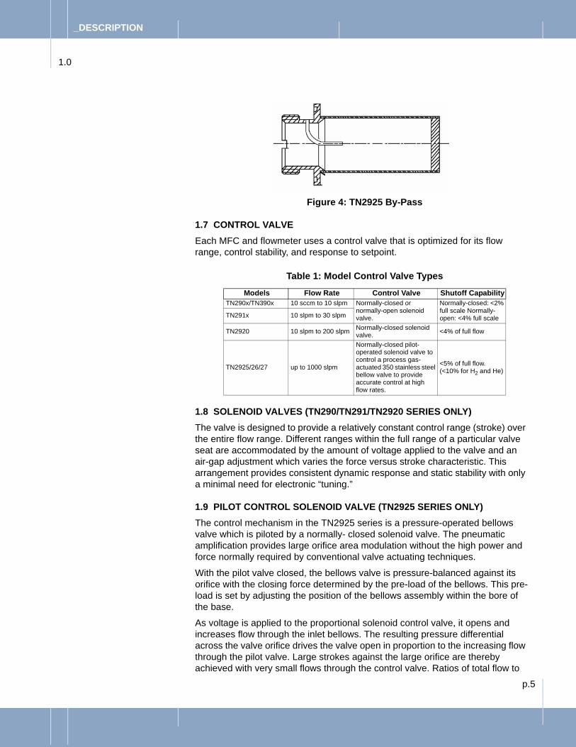
The TN2925 By-Pass is non adjustable as shown in Figure 4.
Figure 3: Cylindrical Screen Bypass
1.0
_DESCRIPTION
p.5
Figure 4: TN2925 By-Pass
1.7 CONTROL VALVEEach MFC and flowmeter uses a control valve that is optimized for its flow range, control stability, and response to setpoint.
Table 1: Model Control Valve Types
1.8 SOLENOID VALVES (TN290/TN291/TN2920 SERIES ONLY)The valve is designed to provide a relatively constant control range (stroke) over the entire flow range. Different ranges within the full range of a particular valve seat are accommodated by the amount of voltage applied to the valve and an air-gap adjustment which varies the force versus stroke characteristic. This arrangement provides consistent dynamic response and static stability with only a minimal need for electronic “tuning.”
1.9 PILOT CONTROL SOLENOID VALVE (TN2925 SERIES ONLY)The control mechanism in the TN2925 series is a pressure-operated bellows valve which is piloted by a normally- closed solenoid valve. The pneumatic amplification provides large orifice area modulation without the high power and force normally required by conventional valve actuating techniques.
With the pilot valve closed, the bellows valve is pressure-balanced against its orifice with the closing force determined by the pre-load of the bellows. This pre-load is set by adjusting the position of the bellows assembly within the bore of the base.
As voltage is applied to the proportional solenoid control valve, it opens and increases flow through the inlet bellows. The resulting pressure differential across the valve orifice drives the valve open in proportion to the increasing flow through the pilot valve. Large strokes against the large orifice are thereby achieved with very small flows through the control valve. Ratios of total flow to
Models Flow Rate Control Valve Shutoff CapabilityTN290x/TN390x 10 sccm to 10 slpm Normally-closed or
normally-open solenoid valve.
Normally-closed: <2% full scale Normally-open: <4% full scaleTN291x 10 slpm to 30 slpm
TN2920 10 slpm to 200 slpm Normally-closed solenoid valve. <4% of full flow
TN2925/26/27 up to 1000 slpm
Normally-closed pilot-operated solenoid valve to control a process gas-actuated 350 stainless steel bellow valve to provide accurate control at high flow rates.
<5% of full flow. (<10% for H2 and He)
1.0
_DESCRIPTION

p.6
pilot valve flow of 200 or more are easily achieved requiring no more force or power than is necessary for a flow control system having less than 1% of the flow capacity.
1.10 ELECTRONICSThe electronics consist of a circuit board with a hybrid Auto-Zero circuit soldered in place. A +5 VDC regulator supplies power to the Auto-Zero circuit and also provides the reference voltage required for the “Valve OFF” function. A -5 VDC regulator provides the reference for the sensor bridge, constant current source, and the linearization circuit.
Table 2: ElectronicsConnection Description
Current Source
Delivers a constant 12.7 mA to the sensor bridge which “floats” between the plus and minus supplies. This arrangement gives extremely high common-mode rejection and allows insensitive operation over a wide range of supply voltage levels. The Sensor Bridge circuit contains the zero and span temperature compensation networks.
Flowmeter Amplifier Circuit
Amplifies the sensor output signal. This circuit also incorporates a speed-up filter which provides for matching the sensor response to the actual flow rate response during a transient flow condition.
Linearity Circuit Provides a variable gain versus input voltage allowing correction for any non-linearity of the sensor output signal.
Auto-Zero Circuit(MFCs only)
Provides periodic correction of zero offset due to long-term sensor drift, temperature and pressure variations, or other environmental causes. This feature ensures long-term calibration accuracy and eliminates the need for periodic manual zero adjustment. The range of correction is limited to ±2.5% of full scale to prevent erroneous correction of an undetectable leak or defective sensor.
The Auto-Zero function is activated either by commanding ≤1% of full scale flow rate which automatically closes the control valve or connecting Pin L to common.
After a 80 to 100 second delay, the output signal is compared with (and driven to) zero within 2.5 seconds. This correction is maintained until the next update. The current or latest correction can be permanently stored in memory by an external command such that in the event of power loss, the output will return to zero when power is re-applied. (Automatic on “D” connectors.
Valve Control Circuit
Compares the flowmeter output signal with the command voltage (setpoint) and varies the voltage to the valve to throttle the flow to the commanded level via closed loop control.
The ramp circuit limits the rate of change of the setpoint allowing the sensor output to “keep-up”, thus minimizing overshoot during step changes in commanded flow rate. If a slower response is desired, jumper JP1 can be removed to give a 10-15% per second rate of change to the desired flow rate.
While the integral and derivative functions of the PID control circuit are relatively fixed, the proportional band (gain) of the circuit is adjusted by the ratio of R52 to R50. The values of these resistors are selected during dynamic response testing to optimize the transient response of the control loop, and vary depending on the range, gas, and intended operating conditions of the instrument.
For Card Edge only: The control logic can be overridden externally to either open or close the valve in accordance with specific process requirements. Note: While connecting Pin D to common may partially open the valve, connecting Pin D to +15 VDC will drive the valve to the full “purge” position.
Balanced Power Load Circuit
Limits the current in the common line to a maximum of ±5 mA. This limits the control error to <0.2% per 100 feet of interconnect cable between the flow controller and its setpoint/readout control system.
1.0
_DESCRIPTION

p.7
1.11 COVERThe cover is made of steel and is grounded to the flow base and the chassis ground connection. This, in conjunction with the roll-off and filter capacitors in the electronics, provides excellent EMI protection.
1.12 SPECIFICATIONS, ELASTOMER SEALED MODELS Table 3: Specifications, Elastomer Sealed Models
TN2900 Series TN2920 Series TN2925 SeriesPerformance
Flow Rate
TN2900: 10 sccm - 10 slpmTN2910: 100 sccm - 30 slpm(TN2910 used below 10 slpm
for low vapor pressure material delivery)
30 - 200 slpm 200 to 1000 slpm
Turndown Ratio Normally-closed: 50:1 normally-open: 20:1 25:1 20:1 (10:1 on H2 and He)
Attitude Sensitivity <0.25% Full Scale @ 90° (without auto-zero)
Step Response Time(dependent on step request and conditions)
1 sec 30 - 100 slpm: ≤ 3 sec100 - 200 slpm: ≤ 6 sec ≤ 5 sec
Accuracy ±1.0% full scale ±2.0% full scale ±2.0% full scale up to 300 slpm±3.0% full scale up to 1000 slpm
Linearity ±0.5% full scale ±1.0% full scaleRepeatability ±0.2% full scale ±0.5% full scaleTemperature Coefficient 0.05% per °C for zero and span 0.01% per °C for zero and span
Pressure Coefficient 0.00001% per bar, 0.007% per psi (typical)
ElectricalSupply Voltage + & -15 VDC nominal ±20%Power Supply Sensitivity <0.01% per volt
Supply CurrentPower
110 mA nominal (125 mA max + & -18 VDC)
±170 mA max. (200 mA max + & -18 VDC)FM: ± 35 mA max. (45 mA max + & -12 VDC)
110 mATN3925/2926: 35 mA
Power Consumption 3.3 watts @ + & -15 VDC
5.1 watts @ + & -15 VDC FM: 1 watt @ + & -12 VDC
Input/Output Signal
0 -5 VDC(Optional TN2901/02: 4 - 20 mA DC)
0 -5 VDC(Optional TN2921: 4 - 20 mA DC)
0 -5 VDC(Optional TN2926: 4 - 20 mA DC)
Input Impedance500K ohms (minimum)(Optional TN2901/02: 250 ohms)
500K ohms (minimum)(Optional TN2921: 250 ohms)
500K ohms (minimum)(Optional TN2926: 250 ohms)
Minimum Load Impedance
2000 ohms(Optional TN2901/02: 250 ohms)
2000 ohms(Optional TN2921: 250 ohms)
2000 ohms(Optional TN2926: 250 ohms)
MechanicalControl Valve Type
Normally-open or normally-closed solenoid
Normally-closed solenoid
Solenoid pilot valve (NC) to control a process gas-activated bellows valve
Materials Exposed to Process Gas
316L stainless steel, 446 stainless steel, PFA Teflon® fluoropolymer
316L stainless steel, 420 stainless steel, PFA Teflon®
fluoropolymer
316L stainless steel, 446 stainless steel, AM-350 SS
Elastomers Available Viton®, Neoprene, or Kalrez® Viton® or Kalrez®
Leak Integrity 1 x 10⁻⁹ atm-cc per sec (He) inboard
1 x 10⁻⁹ atm-cc per sec (He) inboard 1 x 10⁻⁹ atm-cc per sec (He) inboard
1.0
_DESCRIPTION

p.8
1.13 SPECIFICATIONS, METAL-SEALED MODELS
Valve Leak-through
Normal-closed: <2% full scale with Teflon® fluoropolymer poppetNormally-open: <5% full scale with Teflon fluoropolymer poppet
<4% full scale
Surface Finish Internal 0.83 µm (32 µin Ra)
Weight 0.9 kg (2 lbs) 2.0 kg (5.0 lbs) 2.5 kg (5.5 lbs)EnvironmentalProcess/Environmental Temperature Range
0 - 50°C (32 - 122°F) (ambient and gas)
Humidity 0 - 95% Relative Humidity, non-condensing
Maximum Inlet Pressure 10.3 bar (150 psig)
10.3 bar (150 psig) proof: 34.5 bar (500 psig)TN3920: 34.5 bar (500 psig)proof: 103.4 bar (500 psig)
10.3 bar (150 psig) proof: 34.5 bar (500 psig)TN3925/3926: 34.5 bar (500 psig)proof: 103.4 bar (500 psig)
Minimum Inlet Pressure 175 kPa (10 psig) 100 Torr
Maximum Differential Pressure
10 sccm to 10 slpm:70 - 280 kPa (10 - 40 psid)10 - 30 slpm:105 - 280 kPa (15 - 40 psid)
30 - 99 slpm: 140 - 350 kPa (20 - 50 psid)100 - 150 slpm: 210 - 420 kPa (30 - 60 psid)151 - 200 slpm: 280 - 420 kPa (40 - 60 psid)TN3920: 5 psid max
200 - 300 slpm: 210 - 420 kPa (30 - 60 psid)301 - 800 slpm: 276 - 552 kPa (40 - 80 psid)801 - 1000 slpm: 345 - 552 kPa (50 - 80 psid)TN3925/3926: 5 psid max
Minimum Environmental Pressure
>100 Torr (2 psia)
Table 4: Specifications, Metal Sealed ModelsTN2900M TN2930M TN2936MEP/TN2936MEP
PerformanceFlow Rate 10 sccm - 30 slpmTurndown Ratio 50:1Step Response Time(dependent on step request and conditions)
500 msec
Accuracy ±1.0% full scaleLinearity ±0.5% full scaleRepeatability ±0.2% full scaleReproducibility ±0.3% full scale/10 weeksAttitude Sensitivity <0.25% Full Scale. @ 90° (without auto-zero)Temperature Coefficient 0.05% per °C for zero and span
Pressure Coefficient 0.00001% per bar, 0.007% per psi (typical)
Auto-Zero Option
Delay Time: 80 ±20 secCorrection Time: <2.5 sec
Resolution: 0.1% of full scaleRange: ±2.5% of full scale
ElectricalSupply Voltage + & -15 VDC nominal ±20%
Table 3: (Continued) Specifications, Elastomer Sealed ModelsTN2900 Series TN2920 Series TN2925 Series
1.0
_DESCRIPTION

p.9
Power Supply Sensitivity <0.01% per volt
Supply CurrentPower
110 mA nominal,
(Optional: 130 mA nominal, 150 mA max @ 18 VDC)
Power Consumption 3.3 watts @ + & -15 VDC
Input/Output Signal0 -5 VDC
(Optional: 4 - 20 mA DC)
Input Impedance 500K ohms (minimum)Minimum Load Impedance
2000 ohms(Optional: 250 ohms)
Mechanical
Control Valve Type Normally-closed solenoid Normally-open or normally-closed solenoid
Materials Exposed to Process Gas
316L SS, 321 SS 446 SS, Nickel 200, Ruby, TA Ceramic
Leak Integrity 1 x 10⁻¹⁰ atm-cc per sec (He) inboardValve Leak-through <2% full scale Surface Finish Internal
0.4 Ra, avg (non EP)EP: 0.25 µRa, max (EP)
ConnectionsInlet/Outlet, Mechanical
1/4” VCR® 1/4" buttweld 1/4” VCR®
EnvironmentalOperating Temperature Range 0 - 50°C (ambient and gas)
Humidity 0 - 95% Relative Humidity, non-condensingMaximum Inlet Pressure 10.3 bar (150 psig)
Maximum Outlet Pressure
Maximum Differential Pressure
10 sccm to 10 slpm:70 - 280 kPa (10 - 40 psid)
10 - 30 slpm:105 - 280 kPa (15 - 40 psid)
Minimum Environmental Pressure
>100 Torr (2 psia)
Warranty 1 year or 100,000 cycles
Table 4: (Continued) Specifications, Metal Sealed ModelsTN2900M TN2930M TN2936MEP/TN2936MEP
1.0
_DESCRIPTION

p.10
2.0 INSTALLATION
1. Install the MFC or Flowmeter in a proper plumbing configuration
2.0.1 Isolation/Shut-off ValvesAn MFC is NOT a positive shut-off device. When commanded closed, an MFC will allow a small flow through the device. You should install two isolation/shut-off valves with EACH MFC to ensure positive shut-off and to protect the MFC: install one shut-off valve upstream to eliminate flow surge during turn-on and one shut-off valve downstream to prevent back migration of contaminants into the MFC. These shutoff valves will also allow you the ability to more easily conduct in-place testing of the MFC with verifiable zero flow.
2.0.2 Tubing Cleanliness Tubing should be pre-cleaned and polished to eliminate particulate contamina-tion and ensure leak-tight operation.
2.0.3 In-line Filter/PurifierAn in-line filter or purifier should be installed just upstream of the MFC to prevent the possibility of any foreign material entering the flow sensor or internal control valve. Be sure to size the filter for the proper flow rate and pressure drop rating as needed for your gas line. Depending on your gas type and process, a purifier may be desired. Consult a Celerity Gas Applications Specialist for your applica-tion.
2.0.4 Fittings• Gasket Seal (fittings compatible VCR® connection):
Always use a new metal gasket each time you make-up the fitting. Never re-use gaskets as they will leak. Verify that you are using a gasket that is compatible with your gas type, then tighten the gasket seal fittings 1/8 turn past hand-tight for 3/8" and larger fittings, or a maximum of 1/4 turn past hand-tight for 1/4" fittings. DO NOT overtighten. Refer to fitting manufacturer’s instructions for details for your fitting material and size.
• Compression Seal (fittings compatible with Swagelok® connections): Tighten compression seal fittings per manufacturer’s instructions. Typically 1 1/4 turn past hand-tight to initially make-up the fitting. Then 1/4 turn past hand-tight to re-tighten previously made-up fittings. Use the manufacturer’s inspection gauge to ensure that the fitting is properly tightened.
2. Ensure a proper operating environment • CLEANLINESS: For maximum performance and service life, the instrument
should be installed in a clean, dry atmosphere, relatively free of shock and vibration.
• ACCESS: Ensure that there is sufficient room for access to the electronics and plumbing to facilitate maintenance and removal for cleaning.
• RF ISOLATION: Avoid installation of the instrument in close proximity to high sources of RF noise and/or mechanical vibration. If this is unavoidable, proven methods of instrumentation filtering, cable shielding, and/or shock mounting should be utilized.
WARNING! !LEAK HAZARD. Protect the fittings!Fitting caps should not be removed from the instrument until installation. Scratches and dents on the fittings will cause the systems to leak.
2.0
_INSTALLATION

p.11
• TEMPERATURE: The instrument may be operated at any temperature from 0 to 50°C, provided the gas and ambient temperatures are maintained equally. Since the indicated flow rate has a temperature coefficient of ±0.05% per °C. You may want to calibrate the instrument at the actual operating temperature to maximize the measurement accuracy. Contact your Celerity Applications Specialist for details.
• PRESSURE: Flow controllers may be operated at any gas pressure up to 1135 kPa (150 psig or 10.3 bar). Since the indicated flow rate varies in direct proportion to specific heat (Cp), which varies differently with pressure and temperature depending upon the molecular structure of the gas, it is recommended that the instrument be calibrated at the actual operating pressure.
NOTE: The pressure coefficient of ±0.001% per kPa (±0.007% per psi) generally applies to monatomic and diatomic gases only.
3. MountingRefer to the dimensional drawings. Two (8-32 UNC or 10-32 UNC) tapped holes are provided for mounting.
4. Connect the electronicsRefer to the appropriate electrical hookup diagram on page 12 or 13.
Table 5: ElectronicsConnection Description
PowerAny + & -15 VDC power supply meeting the requirements as designated in the specifications may be used to energize the instrument.
Control Signal
Any 0 to 5.0 VDC command voltage having a source impedance of 2500 ohms or less may be used. The input impedance of the flow controller is 0.5M ohm (minimum). (4-20 mA current option is available on selected models)
Output Indication
Any 0 to 5.0 0 VDC meter with at least 1000 ohms/volt can be used to provide visual indication of the mass flow rate. Recorders, voltage dividers (for conversion to engineering units), and other instrumentation may be added, provided the total load impedance is no less than 2000 ohms. The source impedance of the flowmeter output signal is less than 0.5 ohm. (4-20 mA current option is available on selected models)
Valve OFF
A TTL low signal will override the control signal, close the valve and trigger the Auto-Zero function. TTL high (or open connection) allows normal control operation. (Not available on 9-Pin "D" models.)
Valve Test (Override)
The valve voltage may be monitored during normal operation using a high input impedance DVM. Connecting this pin to common or the +15 VDC supply will override the control signal and open the valve. A maximum current of 75 mA is required for the TN2900 and TN2925 Series, 125 mA for the TN2920 Series.
Zener TestThe internal negative reference voltage (-5 VDC) may be monitored for troubleshooting purposes using a high impedance DVM (+5 VDC on the subminiature "D" connector version).
Following forCard-Edge Only:
Auto-Zero InhibitThe Auto-Zero function may be inhibited (deactivated) by applying a TTL low signal. This pin may also be used as an output, as it goes high during the 2.5 second adjustment cycle.
Auto-Zero StoreMomentary application of a TTL low signal stores the latest zero correction in memory. This is automatically recalled on power up (Automatic on TN2901/02).
Auto-Zero Trigger
The Auto-Zero function may be triggered by applying a TTL low signal to Pin L. This will override the setpoint signal and close the valve. Note: Shorting to common may be substituted for TTL low, and open connections substituted for TTL high.
CAUTION !!Proper differential pressure from the inlet pressure to the outlet is critical to the correct operation of the device. Too high or too low of a differen-tial pressure can cause the device to oscillate or provide incorrect outputs.
2.0
_INSTALLATION

p.12
Figure 5: Card Edge and 15 Pin “D” Electrical Hookup Diagram
C--- A B 2 3 F 4 1 L 6 D J K611 8 1 9 2 10 5 14 15 --- 12 3 ---
Card Edge15-pin “D” 2
J8
K L9 10
8 1
915
FLOWN.C. Series
Shut-off Valve(optional)
Valve Test(Over Ride)
Zener
(-5.0 VDC)Valve OFF
ChassisGround
+15 VDCSupplyCommon
AZ Store1
AZ Inhibit1
TTL High = Control ModeTTL Low = Closed (Auto-Zero Trigger)
Store1
Inhibit1
Active1
Open
Purge
Control Mode-15 VDC
Supply
0-5 VDCOutputSignal
+
-
-
+
0-5 VDCCommand
Signal2
+5 VDC Ref
Solenoid SupplyVoltage
1 Auto-Zero (AZ) circuit is not available on TN2900B, TN2910B, and flow meters.AZ Store is internally automatic on TN2901, TN2911, and TN2901M and TN2926.
2 The following is optional by request on TN2901, TN2911, TN2901M, TN2926
Pin-7, 4-20 mA In (MFC only); Pin-4, 4-20 mA Out.
Notes:
Test Point
TN3901, TN3911, TN3901M, and TN3926 only:
A B C D1 2 3 4
E5
F6
2.0
_INSTALLATION

p.13
Figure 6: 9 Pin “D” Electrical Hookup Diagram5. Test the cablesTest the interconnect cable for continuity, pin-to-pin shorts, and correct pin assignments per the electrical hook-up diagram.
6. Leak-Check the System NOTE: After installation of the instrument and prior to its use, the gas delivery system
should be thoroughly leak tested and purged prior to use. (Recommended level for elastomeric seals is l x l0-9 atm cc/sec of helium, or less.) If the MFC is equipped with a normally-closed control valve, you MUST command the valve to the open position to purge the MFC. With a + & -15 VDC power supply, apply 5 VDC (full flow setpoint), or connect the Valve Test point to +15 VDC.
7. Purge the gas linesApply + & -15 VDC power and allow a 30 minute warm-up time before pressuriz-ing the system with PURGE gas. Fully-open the MFC or flowmeter and perform a cycle purge of the gas system.NOTE: A “cycle” purging technique is more effective in removing atmospheric contami-
nants than a simple continuous purge gas flow. To cycle purge, alternate the flow of purge gas with a pump-down of the gas system to vacuum for several cycles. If vacuum is not available, reducing the pressure to 101.325 kPa (0 psig) for several cycles should be adequate. Cycle purging helps remove contaminants from small, blind cavities in the system which constitute a virtual leak source.
DANGERLEAK HAZARD.CRITICAL: You must leak check all system fittings prior to use. Failure to leak-check the system with proper helium leak-checking techniques could compromise the integrity of the system, the process, your equipment, and could endanger personnel.
2.0
_INSTALLATION

p.14
NOTE: If the MFC is equipped with a normally-closed control valve, you MUST com-mand the valve to the open position to purge the MFC. With a + & -15 VDC power supply, apply 5 VDC (full flow setpoint), or connect the Valve Test point to +15 VDC.
8. MFCs - Verify the device flow • Apply + & -15 VDC power and allow a 30 minute warm-up time before
pressurizing the system with PROCESS gas. If the indicated output does not settle to zero to within 1% full scale (or the level of zero desired), re-zero the instrument (see Adjustment Procedures, page 18) before proceeding.
• Once the zero has been verified, pressure may be applied. After establishing that no hazardous condition will be created by the venting of process gas, flow controller operation may then be verified over the complete operating range. If the flow output voltage is within 10 millivolts of the setpoint, the flow controller is controlling properly. Check for this condition at the highest and lowest flows anticipated at both the highest and lowest input-output pressure differentials anticipated.
Every effort has been made in the design of the instrument to provide safe, trou-ble-free operation. Key features include reverse power supply polarity protec-tion, output over-voltage and short circuit protection, low component temperatures, and conformance to intrinsic-safety design criteria. Additionally, a built-in “threshold” circuit ensures that the valve is commanded open at zero command independent of any existing output offset, the valve automatically opens with power failure.
For the operator’s convenience during start-up, abnormal, or fault conditions the valve command circuit can be overridden externally to drive the valve fully closed. Connecting signal Ev to common will override the control signal and close the valve. Re-adjustment of the valve after purging or repair is described in the Adjustment Procedures, page 18.
9. Calibration Each instrument is factory calibrated for the specific flow range and gas indi-cated on the nameplate. Standard factory calibration is within ±2.0% and is refer-enced to standard temperature and pressure. The calibration for other gases can be approximated to ±6% using the Conversion Factor Charts available from Celerity’ web site. Factory calibration utilizes the test gases detailed in the charts. Calibration checks with other gases can show discrepancies of up to ±6%. Precision calibration equipment is required to obtain calibration accuracy of ±2% after range change or for other gases. Range changes can be made to within ±10% by removing the inlet fitting and adjusting (or replacing) the bypass. Fine tuning to the desired accuracy level can then be accomplished by adjusting the potentiometers on the printed circuit board in conjunction with a reference flow standard, as detailed in the Adjustment and Calibration Procedures avail-able from the Celerity web site "www. Celerity.net"NOTE: In accordance with Semiconductor Equipment and Materials Institute Standard
E12-91, Standard Pressure and Temperature are defined as 101.325 kPa (760mm Hg) and 0°C respectively.
WARNING! !DO NOT convert an elas-tomer sealed instrument, originally calibrated for a non-reactive, non-corrosive gas to use reactive or corro-sive gas unless all the seals are replaced with the suitable compound. Any instrument which has been in reactive or corrosive gas service should be thoroughly purged and cleaned prior to conversion to another gas. Instruments are factory assembled using:- Viton® for non-reactives, - Neoprene for Ammonia, - Kalrez® for all other reactive and corrosive gases unless specified otherwise. Cycle-Purge the gas system.
2.0
_INSTALLATION

p.15
3.0 OPERATION
3.1 START-UP1. Apply + & -15 VDC power and allow the instrument to warm-up for 30 minutes
before pressurizing the system with process gas.2. If the indicated output does not settle to zero or within ±1% full scale (or the
level of zero desired): re-zero the instrument (see Adjustment Procedures,page 18) before proceeding.
3. Once the zero has been verified, pressure may be applied. After establishing that no hazardous condition will be created by the venting of process gas, flow controller operation may then be verified over the complete operating range. If the flow output voltage is within 10 millivolts of the setpoint, the flow controller is controlling properly. Check for this condition at the highest and lowest flows anticipated at both the highest and lowest input-output pressure differentials anticipated.
3.2 OPERATING MODESIn general, the instruments may be operated at any pressure and temperature that falls within the limits stated in the specification. Optimum performance, how-ever, can be achieved and will prevail if the operating pressure and temperature are pre-determined and controlled to a narrow range. Calibrating and “fine-tun-ing” the instrument at the actual operating pressure, temperature, and flow rates can significantly improve the performance characteristics.
The instruments are factory calibrated at an ambient temperature of 23°C (±3°C) and the inlet pressure set to the midpoint of the operating pressure range and corrected to standard conditions. Flow controllers are adjusted to pass full rated flow at the minimum inlet pressure, with 101.325 kPa (0 psig) outlet pressure and shut down to less than 2% (TN2900 Series) or 4% (TN2920 and TN2925 Series) of full scale at the maximum inlet pressure. Response time is verified at both extremes.
3.3 USE IN VACUUM SYSTEMS:In vacuum systems, flow controllers maintain their calibration accuracy due to the pressure drop of the control valve downstream of the flow sensing section. The increased pressure drop of the valve due to the increased gas velocity reduces the full-scale flow rate and unless there is sufficient inlet pressure avail-able to overcome the increased pressure drop required, increasing the range of the instrument and/or re-adjustment of the valve may be necessary.
3.4 NORMALLY-CLOSED VALVES:For normally closed valves, it is not necessary to provide an external time-delayed “soft-start” signal provided the command signal is maintained at zero during the “OFF” mode and is then applied to the instrument at the same time (or after) pressure is applied. Alternately, Pin L connected momentarily to common prior to applying gas pressure also prevents excessive flow transients at turn-on. A slower ramp change may also be selected for vacuum systems which have small volumes and large flow rates or in other applications where a slower ramped change in flow rate is desirable.
3.0
_OPERATION

p.16
3.5 SAFETY FEATURES AND PRECAUTIONSEvery effort has been made in the design of the instrument to provide safe, trou-ble-free operation. Key features include reverse power supply polarity protec-tion, output over-voltage and short circuit protection, low component temperatures, and conformance to intrinsic-safety design criteria. Additional fea-ture:
• A built-in “threshold” circuit ensures that the valve is commanded closed at zero command independent of any existing output offset.
• Normally-closed valves: automatically closes in the case of a power failure. • Normally-open valves: automatically open in the case of a power failure.
3.6 MANUAL OVERRIDES•Normally-closed valves: To drive the valve open: connect Pin D (card edge) or Pin 12 (15-Pin "D" con-nector) to 0 VDC or +15 VDC.To drive the valve closed: connect Pin L to 0 VDC. (The input to close the valve provided on Pin L is active low and conforms to TTL Logic levels.)•Normally-open valves:To drive the valve closed: connect Pin D (card edge) or Pin 12 (15-Pin "D" connector) to 0 VDC or +15 VDC.To drive the valve open: connect Pin L to 0 VDC. (The input to close the valve provided on Pin L is active low and conforms to TTL Logic levels.)
Should there be a need to purge the system during a power failure or instrument malfunction prior to removing the instrument from the system for repair, the valve may be mechanically opened by first removing the instrument cover and then loosening the lower lock nut and turning the housing of the valve one or two turns counterclockwise. Readjustment of the valve after purging or repair is described on page 19Thoroughly leak test the entire system prior to operation (recommended level for elastomer seals is 1 x 10⁻⁹ atm cc/sec. of helium or less).
• Use only clean, moisture-free (dry) gases.• Purge only with dry nitrogen (or other inert gas) before and after breaking
into the system. Be sure to OPEN a normally-closed valve.• DO NOT purge reactive gas systems with inert gases between runs unless it
is required by the process. Even “dry” gases contain some amount of mois-ture which will result in contamination build-up.
• ALWAYS command no flow or ground Pin L when the gas supply is shut off. The command signal should be interlocked with a series shutoff valve to prevent unnecessary over-heating of the control valve during shutoff, and excessive flow surges after turn-on.
• Avoid installation of the instrument in close proximity to high sources of RF noise and/or mechanical vibration. If this is unavoidable, proven methods of instrumentation filtering, cable shielding, and/or shock mounting should be utilized.
3.0
WARNING! !YOU MUST leak-check the system plumbing with proper leak check equipment after any mechanical adjustment has been performed on the valve.
WARNING! !The following precautions should be taken to prevent damage, minimize safety haz-ards, and maximize perfor-mance:
WARNING! !NEVER insert or uplug the connecting cable of the con-trol valve leads with power on if there is a possibility that the ambient atposhpere might be explosive.
_OPERATION

p.17
4.0 MAINTENANCE
NOTE: The following instructions and procedures are intended for a laboratory bench top environment. Proper equipment and precautions should be used for any other system or environment.
4.1 PERIODIC TESTING/CALIBRATIONCelerity recommends that you return the MFC to a Celerity Service Center for cleaning and calibration at least once each year, or as directed by local proce-dures to ensure optimum process repeatability and optimum product yields. The optimum (or necessary) service period is dependent on usage, environmental conditions, gas corrosiveness, and related factors, and must be established based upon historical experience in your particular application.
1. Purge the instrument with dry nitrogen for a minimum of 30 minutes prior to removal from the system.
2. Verify the calibration of the flow metering section by comparison with a suitable reference standard or calibrator.
3. Operate the instrument in the control mode over its entire operating range at the minimum and maximum inlet pressures. Check response, stability, and control resolution.
4. Based upon these results, either re-install the device as directed by Celerity technical support or send to the device to Celerity for cleaning and calibration.
4.2 CLEANINGShould the instrument show symptoms of internal flow path contamination, it may be disassembled and cleaned. Contamination of the ultra clean surface may cause irreparable damage depending on the severity of contamination.
4.3 DISASSEMBLY PROCEDURE:1. Remove power to the device.2. Remove the screws that secures the cover to the base.3. Unplug the valve from the PC Board.4. Remove the screw and standoff that secures the valve to the base and pull
the valve assembly out completely.5. Remove the other standoff that supports the cover.6. Remove the PC Board from the assembly and, remove the two screws which
secure the sensor assembly to the base.7. Remove the inlet fitting and outlet fittings.8. To remove the bypass, hold the flow controller in a vertical position (inlet
down) and carefully remove the assembly. For slotted-disc devices, note that the discs will be loose. BE CAREFUL not to drop or damage the discs. BE SURE TO NOTE THE ORDER IN WHICH THE DISCS ARE INSTALLED as you will need to replace them in the same order.
4.4 CLEANING PROCEDURE1. Run a heated ultrasonic cleaner with DI water for a minimum of 5 minutes.
Hand clean each part with cleanroom wipes. Reclean using fresh DI water.
CAUTION !!SHOCK HAZARD.Always make sure power is off before disconnecting or reconnecting the valve to the PC Board.
CAUTION !!Do not submerge electronics, sensor or valve coil. Use of harsh solvents, chemicals or HF will likely cause irrepara-ble damage to surface fin-ishes.
4.0
_MAINTENANCE

p.18
2. Dry parts in a vacuum oven for 30 minutes. Maintain and observe cleanroom practices during the cleaning process in preparation for re-assembly.
3. Clean the sensor by running an 0.18 mm (.007 inch) diameter wire (stainless steel or piano) through the full length of the sensor tube 3 or 4 times. If possible, force DI water through the sensor then dry with ultra-pure nitrogen.
4.5 RE-ASSEMBLY PROCEDURE:Re-assembly should be done in a Class 100 cleanroom environment which includes use of tools and fixtures.
1. Inspect all surfaces under high power magnification for surface degradation. Replace any suspect parts.
2. For slotted-disc devices, the nut and discs should be reassembled in the same order as originally installed (slots upstream, facing shoulder of the nut). Reinstall the bypass and torque to 15 in·lb using the bypass adapter on the torch wrench.
3. Install the inlet fitting.4. Install sensor using new seals. Torque Allen screws 15 in·lb. Re-install the PC
Board to the sensor with screw and spacer.5. Install the valve using a new seal and the original centering ring, and torque
the Allen screws to 15 in-lb. It will also be necessary to readjust the valve (refer to the Valve Adjustment Procedure).
6. Secure cover support standoffs to the base.7. Leak check the device to 1 x 10⁻¹⁰ atm cc/sec Helium.8. Calibrate the device per the calibration procedure.9. Re-install the cover.
4.6 ADJUSTMENT AND CALIBRATION PROCEDURESIn order to maintain the original factory calibration and performance characteris-tics of the instrument, the following adjustments may be necessary during rou-tine maintenance and servicing. It is required after any disassembly of the device.
4.7 CALIBRATION PROCEDURE - INDICATED VERSUS ACTUAL FLOWEach controller is factory calibrated for the specific flow and gases indicated on the nameplate. Standard factory calibration is within ±1.0%. The calibration for other gases can be approximated to ±5% by using conversion factors available from Celerity. (See Caution)
1. Thoroughly flush and dry the instrument to remove contaminants (see Cleaning Procedures).
2. Connect a source of gas to the inlet and a suitable flow standard to the outlet. If a volumetric calibrator is used, be sure to apply the proper density corrections to maintain the mass flow calibration.
3. Connect the power and indicator wires (see Electrical Hook-up Diagram) and allow a 30 minute warm-up period.
4. OPEN THE VALVE: Ensure that the valve is open. For normally-closed valves, either mechanically open the valve by turning the valve housing 2 to 3
CAUTION !!You MUST re-calibrate the MFC after replacement or removal for cleaning of the bypass assembly. A calibra-tion shift of as much as 10% may occur during cleaning, depending on the level of contamination.
CAUTION !!Factory adjustments should not be altered unless preci-sion gas flow measuring equipment is available for calibration. Rotometers do not have sufficient accuracy for flow measurement cali-bration unless they have been specifically calibrated and the proper corrections are made for temperature and pressure.
4.0
_MAINTENANCE

p.19
turns counter-clockwise, or electrically drive the valve open.5. Remove the outlet gas line and cap off the instrument to assure zero flow
through the sensor. 6. Adjust ZERO potentiometer RP1 to make the indicator read zero (± 5 mV).7. Reconnect the outlet gas line and adjust the flow to 40% full-scale value. Set
the output to read 2.00 VDC at the full-scale flow rate using the GAIN potentiometer RP2.
8. Recheck zero as described in Step 6.9. Linearity adjustments are not normally required. After achieving calibration at
zero and maximum flow, the full scale calibration may be checked by setting the flow to cause the indicator to read 2.50 VDC. The calibrator should then measure 1/2 of the full range flow rate. If not, set the flow rate to one-half of the full scale value, and adjust the output to 2.50 VDC using the LINEARITY potentiometer RP4.Although this adjustment is essentially independent, steps 5 through 7 should be repeated until all three points are within the desired calibration.
10. The flowmeter section of the flow controllers can be calibrated with the instrument operating in the controller mode and using the setpoint control to dial in the desired flow rate. Adjustments should be made as in steps 5 through 9. When adjusting the gain and linearity potentiometers, the actual flow will change rather than the output voltage since the controller acts to control the output voltage to the commanded setpoint voltage.
11. If the instrument cannot be brought into calibration within the adjustment range of GAIN or LINEARITY, the flowmeter amplifier gain and/or bypass will have to be adjusted. See “Range Change” on page 22.
12. When using a test gas other than the intended usage gas, a correction factor equaling the ratio of the conversion factors of the two gases must be applied. Contact Celerity for the correction factors.
4.8 VALVE ADJUSTMENT (MFCS ONLY)(See page 37 for TN-2920 and TN2925 series valve adjustment)
4.9 TN2900 SERIES ONLY:1. Remove the cover to permit access to the valve assembly.2. Connect the inlet of the instrument to a regulated supply of the appropriate
gas at the appropriate pressure. Connect a reference flowmeter in series, or monitor the flow as measured by the controller.
3. OPEN THE VALVE: Open the valve, or electrically disconnect for a normally-open valve.
4. Slowly apply inlet pressure to the controller to 380 kPa (40 psig) or the maximum pressure (see Specifications) and command zero flow.
5. Loosen the lock-nut then SLOWLY turn the adjustment nut clockwise until the flow is reduced to less than 2% of full scale. Cycle the valve from 0% to 100%
Series ZeroAdjust
100% Full Scale
(GAIN)
40% Full Scale
(LINEARITY)TN2900TN2920TN2925
RP1 RP2 RP4
4.0
_MAINTENANCE

p.20
then from 100% to 0% full scale to ensure consistent valve closure of less than 2% of full scale.
6. Set the inlet pressure to the minimum expected value and command 100% flow rate. Verify full-scale output. While monitoring the voltage applied to the valve, mechanically fine-tune the valve adjustment to achieve as close to the optimal control voltage as possible.
7. Repeat this process until the valve controls from <2% (See chart below) to 100% full scale at both extremes of pressure. Do not exceed the optimal control voltage.
8. After the valve is properly adjusted and tuned dynamically (see Dynamic Response Adjustment procedure), tighten the lock nut on the top of the valve with 10 to 20 inch-pounds of torque. This will lock the adjusted position in place.
9. Leak check the controller.NOTE: If the valve still exhibits excessive leakage, the seat may be contaminated or
damaged. Clean or replace the valve. Before replacing the valve, check the O-ring seal for nicks, cuts, or damage and replace if necessary to ensure an ade-quate seal between the valve body and the base.
4.10 DYNAMIC RESPONSE ADJUSTMENT (MFCS ONLY):
TN2920 Series
Each flow controller is dynamically adjusted prior to shipment using a flow mea-suring device, in series, which is as least 5 times faster than the instrument under test (for experimental details, refer to SEMI Standard E12-91). This veri-fies that the tuned indicated response is indicative of the actual flow response and does not mask or filter-out overshoot or oscillatory flow conditions. It is rec-ommended that the adjustments not be altered unless suitable equipment is available to adequately display the transient results. If it is found necessary to readjust the response characteristics following cleaning, reassembly, valve adjustment, or range change, the following steps may serve as a guideline.
1. Start with the previously set adjustment, or alternately center potentiometer RP3 and set R50 to 200k ohms.NOTE: A resistance decade box is useful for finding the optimum value for R50.
2. Supply the instrument with the intended usage gas or a suitable substitute gas at the intended operating conditions including inlet pressure.
SeriesPin to Monitor Optimal
Control VoltageCard-Edge 15-Pin D
TN290x
Pin D to Pin F Pin 12 to Pin 6
13 VDCTN2910/TN2911/TN2912
TN2920/TN292117 to 20 VDC
TN2925/TN2926
Series Valve ControlTN2900 Series <2%
TN2910/TN2911/TN2912TN2920Series <4%
TN2925/TN2926<5%
<10% for H2 or He
CAUTION !!The control valve is not designed for positive shut-off. Do not attempt to adjust clo-sure to less than 1% or the valve may be damaged.
4.0
_MAINTENANCE

p.21
3. Generate step changes of the setpoint signal. For example, 50% to 100% and vise versa, and watch the output signal using a storage oscilloscope or a fast chart recorder.
4. Adjust RP3 to produce as near a square wave as possible. If a fast actual flow measuring device is used in series to view actual response, adjust RP3 to match the indicated response to the actual response.
5. Once RP3 has been optimized, reduce R50 to minimize the overshoot without causing oscillations or instability. R52 may also be varied if necessary to achieve optimal results. A high ratio of R52/R50 will provide the fastest response and minimal overshoot, but is more inclined to result in oscillation and instability. R50 should be minimized to prevent long delays at low setpoints.
6. Once the response has been optimized, the response characteristics should be checked at various step changes in setpoint over the expected operating pressure range. It is advisable that the value or R50 be increased by 50% as a last step to preclude the possibility of instability developing after installation.NOTE: Complete re-calibration and dynamic response adjustment will also be required any time the sensor assembly or PC Board assemblies are replaced.
4.11 BYPASS ADJUSTMENT
TN2920 Series ONLY
To change the range of the instrument, an adjustment may be made if the desired range in within the range of the installed bypass. Otherwise, it must be replaced. A three digit number etched on the bypass is used to identify its range as follows:
-001: 25 to 100 slpm
-002: 50 to 200 slpm
-003: 100 to 400 slpm
If the desired range is within the range of the installed bypass assembly, adjust as follows:
1. Remove the bypass assembly as described in the cleaning section.2. Using a 1/8” phillips head screwdriver, adjust the center screw by turning
counter-clockwise to locate the plug flush with the downstream end of the screen.
3. Thread the bypass back into the flow body and firmly tighten against shoulder.4. Adjust the bypass by turning the adjusting screw clockwise to decrease the
full scale flow.Adjustment resolution for various high flow bypass sizes are approximately as follows:
-001: 1.2 slpm per turn-002: 2.5 slpm per turn-003: 5.0 slpm per turn
CAUTION !!CAUTION: Press the screw firmly against the bypass nut during adjustment to ensure that the threads only engage the plug and not the hub. Make sure that the screw does not thread out of the assembly during counter-clockwise adjustment.
4.0
_MAINTENANCE

p.22
4.12 TN2900 AND TN2936 BYPASS ADJUSTMENTSince the bypass is pre-assembled to a specific range, it is as such, non adjust-able. Minor adjustments can be made, however, by removing or adding discs to bring the calibration within range of the adjustment potentiometers. (Removing discs reduces the range proportionately, while adding discs increases the range). Bypass adjustment is not recommended by anyone other than a quali-fied service technician who has been factory trained in the serviceability of the instrument. Contact Celerity Technical Support for help.
4.13 RANGE CHANGEYou must return the device to a Celerity authorized service center for any range change to ensure safe operation and maintain your product’s warranty.
4.14 MAINTENANCE TOOLSThe following table describes some general tools needed for the maintenance of the TN29xx Series Mass Flow Controllers and meters. Consult a Celerity repre-sentative for current part number and availability.
Table 6: Maintenance ToolsDescription
Torque wrench, 10-in·lb Wire, mandrelTorque wrench, 15-in·lb (sensor) X-Acto® KnifeTorque wrench, 25-in·lb (bypass) Screwdriver, 3/4” flatAdaptor, torque wrench (bypass) Screwdriver, 1/8” PhillipsAdaptor, orifice (5/16”) Wrench, Allen (7/64”)Adaptor, use with orifice Wrench, open-end, 5/16” x 1/4”Pot adjustment tool Wrench, open-end, 7/16” x 3/8”Extender board
4.0
_MAINTENANCE

p.23
5.0 TROUBLESHOOTING
5.1 INITIAL TESTRefer to the troubleshooting charts for instructions.
1. Verify all installation steps.2. Test line cord for compliance with pin assignments and continuity from all
wires to correct pin. Use a Hipot tester to check for pin-to-pin shorts; during the test, flex the cable coming out of the connector to find intermittent shorts.
3. Check insulation resistance from Pin 2 to base. It should exceed 50M ohms at 50 VDC. Pin 1 to case should measure less than 1 ohm.
4. Connect a source of gas (same as that for which the instrument is calibrated or equivalent test gas) to the inlet fitting.
5. Apply power and allow a 30 minute warm-up period. With the appropriate inlet pressure applied, the output signal of the controller should follow the command setting (for example, 50% of full scale at 2.50 VDC commanded voltage). Actual flow (as measured by a suitable flow standard in series with the controller) should follow the command setting and agree with the indicated flow of the controller.
6. If the instrument is malfunctioning or cannot be re-calibrated as previously described in the “Adjustment and Calibration Procedures” on page 18, check the appropriate symptom in the Troubleshooting Charts.
5.2 TROUBLESHOOTING CHARTS
Table 7: General TroubleshootingSymptom Possible Cause Remedy
No output
Faulty meterTN125 Series:Read output at Pins B or 2 (common) and H or 7 (Eo) directly with digital voltmeter.
No flow Check pressures, valve positions, line or filter blockage.
Sensor clogged See Cleaning Procedures.
Valve closed
See Valve section. Measure valve DC resistance (should be 220 ohms ±10 ohms). If coil is open, replace coil or entire valve assembly.
Electronic failure See Electronics Section.
No input power Check for line power between appropriate pins at mating connector.
Faulty power supply Check input/output voltages (+ & -15 VDC, +5.00 VDC).
Maximum signal (approximately 200% of full scale):
a: Indication correct, flow is high
Valve failed open
Check valve voltage as measured across valve wires. Valve should close when voltage decreases below 4.00 VDC. Higher voltage indicates lack of closing command or electronic failure; repair or replace electronics.
b: Indication erroneous
Faulty power supply or command signal Check input/output (+ & -15 VDC, +5.00 VDC).
Open resistance element on sensor Replace sensor.
Electronics failure See Electronics Section.
CAUTION !!Permanent damage to the instrument may result if purg-ing procedures are not fol-lowed, or if line power is accidentally applied to the signal leads.
5.0
_TROUBLESHOOTING

p.24
Table 8: Electronics TroubleshootingSymptom Possible Cause Remedy
General failure or mis-calibration Power supply voltage off of nominal. Check + & -15 VDC. Check sensor
and valve or connections.
Flow indication saturated (-0.7 or +12.0 VDC) regardless of flow
Bridge or sensor failure.
Check sensor resistances, these should be 330 ohms ±10 ohms) green to red and green to brown with power off. Voltage across BROWN to RED should be -5.0 ±0.3 3 VDC.
Component failure. Check zero pot, gain pot, other components and solder joints.
Valve drive open or driven off (0 VDC)
TN2900 Series:Valve drive transistor Q3 open or Q2 shorted.
TN2920/TN2925 Series: Valve drive transistor Q3 open or Q5 shorted.
Check components; replace as required.
Valve drive saturated (>20 VDC)
TN2900 Series:Q3 shorted, Op-amp (U1) failed.
TN2920/TN2925 Series:Q3 shorted, Op-amp (U4) failed.
Replace if necessary, or replace PC Board assembly.
All circuits functional, but out of calibration
Contamination, or as a result of cleaning or repairing. Adjust.
Controls, but output voltage does not agree with control input voltage
+5.00 VDC supply of the control input pot off nominal.
Check +5.00 VDC input reference supply.
TN2900 Series:Large input voltage offset in Op-amp (U1).
TN2920/TN2925 Series:Large input voltage offset in Op-amp (U4).
Replace if necessary, or replace PC Board assembly.
Table 9: Valve TroubleshootingSymptom Possible Cause Remedy
Signal offset at zero flow Electronics not adjusted. See Adjustment Procedures.
Valve fails to close
Contamination. See Cleaning Procedures.Electronics failure. See Electronics Section.Mechanical damage from over-pressure or other cause. Adjust or replace valve.
Operation on wrong gas (for example, unit adjusted for argon may not shut off completely on hydrogen).
Test on proper gas or mechanically readjust valve.
Valve failed open (normally open only).
Check valve voltage as measured across valve wires. Valve should close when voltage decreases below 4.00 VDC. Higher voltage indicates lack of closing command or electronic failure; repair or replace electronics.
Valve fails to open
Contamination. See Cleaning Procedures.
Electrically commanded closed or pot shorted
Check command signal ((Pins A and B) and pot. Check for Electronic failure.
Valve controls at flow rates, but not at minimum
Contamination. See Cleaning Procedures.Erosion or corrosion. Replace valve.Improper adjustment or inadequate drive. See Adjustment Procedures.
5.0
_TROUBLESHOOTING

p.25
NOTE: 1: Pin L may be connected to common prior to turning on the gas supply to achieve “soft start” performance.
NOTE: 2: A threshold circuit in the controller ensures zero valve voltage whenever the commanded signal falls below 1.0%.
NOTE: 3: It is not recommended that a failed electronic component be replaced, as com-ponent failures are usually caused by another problem in the device or in the system. It is recommended instead, that the flow controller be returned to Celerity for failure analysis and repair.
5.3 SENSOR REPLACEMENTIf it is determined that either of the sensor elements is open or shorted to case, it will be necessary to replace the sensor assembly. This can be done by unsolder-ing the four sensor leads from the PC Board and removing the four screws which attach the sensor assembly to the base and the PC Board. The sensor assembly can then be removed and replaced. Before installing the new sensor element, resistance should be checked and measured as follows:
Upstream: RU=330±13 ohms at 24°C (Brown to Green).
Downstream: RD=330±13 ohms at 24°C (Red to Green).
Isolation> 100M ohms (All leads to sensor housing)
5.4 SOLENOID VALVE REPLACEMENTIf it is determined that the valve is open, shorted to case or outside the DC resis-tance range of 390 to 420 ohms for TN2900/TN2925 series, or 210 to 230 ohms for TN2920 series, the valve assembly will need to be replaced. Remove the locknut and valve housing to gain access to the coils. The valve must be re-adjusted following the coil replacement.
Valve oscillates or hunts
Erratic pressure in line from upstream pressure regulator.
Constant, stable pressure should be applied to the device. Replace regulator.
Improper system dynamics due to excessive inlet pressure.
Reduce upstream pressure regulator setting. Verify that system is operating within the specified psid range.
Improper dynamics in electronics.Check for failed resistor or capacitor. See Dynamic Response Adjustment Procedure.
Table 9: (Continued) Valve TroubleshootingSymptom Possible Cause Remedy
5.0
CAUTION !!Always command zero flow when the gas supply is shut off. Failure to do so will result in excessive flow transients after the gas supply is turned “ON”. (See Electrical Hook-up Diagram.)
_TROUBLESHOOTING

p.26
5.5 DRAWINGS
Figure 7: Card Edge and 15-Pin “D” Connector Functional Diagram
5.0
_TROUBLESHOOTING

p.27
Figure 8: 9-PIN “D” Connector Functional Diagram
DRAWINGS NOT TO SCALE
5.0
_TROUBLESHOOTING

p.28
Figure 9: PC Board Layout
ELECTRICAL CONNECTIONS
DESCRIPTIONCardEdge
15-Pin “D”
9-Pin “D”
Case Ground 1 14 9*COMMON 2 1 70-5 VDC OUT 3 2 2+15 VDC 4 5 3PRESS. IN. 5 13 9*V REF. 6 11 -4-20 mA IN - 7 6*4-20 mA OUT - 4 2*OVERRIDE - - 10-5 VDC IN A 8 6COMMON B 9 8COMMON C 10 4VALVE TEST(+15 VDC) D 12 8*
-15 VDC F 6 5Az INHIBIT J 3 -Az STORE K - -VALVE OFF L 15 -VALVE VOLTAGE (0-7 VDC)
- 8*
NOTE:P = #8-32 UNF -2B (2PCL’s)
TN2900/TN3900 SERIES
“D” Dim.
“E” Dim.
“F” Dim.
“H” Dim.
“J” Dim.
“K” Dim.
“L” Dim.
“X” Dim.
“Y” Dim.
“Z” Dim. P
2.72”69.10mm
0.140”3.56mm
0.370”9.40mm
0.720”18.28mm
0.50”12.70mm
0.740”18.79mm
1.48”37.95mm
6.18”156.8mm
4.795”121.79mm
3.00”76.20mm
SEE NOTE
5.0
_TROUBLESHOOTING

p.29
Figure 10: TN2900/TN3900 Dimensions and Electrical Connections.
ELECTRICAL CONNECTIONS
DESCRIPTIONCardEdge
15-Pin “D”
9-Pin “D”
Case Ground 1 14 9*COMMON 2 1 70-5 VDC OUT 3 2 2+15 VDC 4 5 3PRESS. IN. 5 13 9*V REF. 6 11 -4-20 mA IN - 7 6*4-20 mA OUT - 4 2*OVERRIDE - - 10-5 VDC IN A 8 6COMMON B 9 8COMMON C 10 4VALVE TEST(+15 VDC) D 12 8*
-15 VDC F 6 5Az INHIBIT J 3 -Az STORE K - -VALVE OFF L 15 -VALVE VOLTAGE (0-7 VDC) - 8*
TN2900/TN3900 SERIES (With Metal Seals)
“D” Dim. “E” Dim. “F” Dim. “H” Dim. “J” Dim. “K” Dim. “L” Dim. “X” Dim. “Y” Dim.2.72”69.10mm
0.140”3.56mm
0.370”9.40mm
0.720”18.29mm
0.50”12.70mm
0.740”18.80mm
1.48”37.59mm
6.045”153.54mm
4.795”121.79mm
5.0
_TROUBLESHOOTING

p.30
Figure 11: TN2900/TN3900 Dimensions and Electrical Connections (With Metal Seals)
NOTE:P = #10 -32 UNF -2B x .22 DP. (2PCL’s)
FITTING & SIZE “A” Dim. “B” Dim. “C” Dim. “D” Dim. “E” Dim. “F” Dim. “H” Dim.
3/8” Swagelok®
6.25”158.7mm
7.00”177.6mm
7.70”195.4mm
4.00”101.6mm
0.63”7.62mm
0.2446.19mm
0.987”25.06mm
3/8” VCR® __ 7.58”192.4mm __ 4.00”
101.6mm0.63”7.62mm
0.2446.19mm
0.987”25.06mm
FITTING & SIZE “J” Dim. “K” Dim. “L” Dim. “X” Dim. “Y” Dim. “Z” Dim. P
3/8” Swagelok®
0.585”14.8mm
0.737”18.7mm
1.475”37.5mm
6.980”177.3mm
5.73”145.5mm
5.255”133.4mm See Note
3/8” VCR® 0.585”14.8mm
0.737”18.7mm
1.475”37.5mm
6.980”177.3mm
5.73”145.5mm
5.255”133.4mm See Note
ELECTRICALCONNECTION
TN2920/TN3920 SERIES
DESCRIPTION CardEdge
15-Pin “D”
Case Ground 1 14COMMON 2 10-5 VDC OUT 3 2+15 VDC 4 5PRESS IN - 13ZENER TEST POINT (-5 VDC)
6 11
4-20 mA IN - 74-20 mA OUT - 40-5 VDC CONTROL A 8
COMMON B 9COMMON C 10VALVE TEST OVERRIDE D 12
-15 VDC F 6Az INHIBIT J 3Az STORE K -VALVE OFF L 15
5.0
_TROUBLESHOOTING

p.31
Figure 12: TN2920/TN3920 Series Dimensions and Electrical Connections.
DESCRIPTIONCardEdge
15-Pin “D”
Case Ground 1 14COMMON 2 10-5 VDC OUT 3 2+15 VDC 4 5PRESS IN - 13ZENER TEST POINT (-5 VDC)
6 11
4-20 mA IN - 74-20 mA OUT - 40-5 VDC CONTROL A 8
COMMON B 9COMMON C 10VALVE TEST OVERRIDE D 12
-15 VDC F 6Az INHIBIT J 3Az STORE K -VALVE OFF L 15
ELECTRICAL CONNECTION
TN2925/TN3925 SERIES
FITTING & SIZE
“D” Dim.
“E” Dim.
“F” Dim.
“H” Dim.
“J” Dim.
“K” Dim.
“L” Dim.
“X” Dim. “Y” Dim.
All 2.25”57.1mm
0.250”6.35mm
0.250”6.35mm
1.50”38.1mm
0.990”25.1mm
0.990”25.1mm
1.98”50.3mm
6.792”172.5mm
5.542”140.7mm
5.0
_TROUBLESHOOTING

p.32
Figure 13: TN2925/TN3925 Dimensions and Electrical Connections.
TN2930MEP SERIES [MEP = metal seals electropolished, 16 µ inch Ra]
FITTING & SIZE "D" Dim. “E” Dim. “F” Dim. “H” Dim. “J” Dim. “K” Dim. “L” Dim. “X” Dim. “Y” Dim. P
All 2.72”69.09mm
0.45”11.43mm
0.390”9.91mm
0.72”18.29mm
0.50”12.7mm
0.74”18.8mm
1.48”37.59mm
6.045”153.54mm
4.795”121.79mm
#8-32 UNC-2B(2 PLACES)
.
DESCRIPTIONCardEdge
15-Pin “D”
9-Pin “D”
Case Ground 1 14 9*COMMON 2 1 7
0-5 VDC OUT 3 2 2
+15 VDC 4 5 3PRESS. IN. 5 13 9*
V REF. 6 11 -
4-20 mA IN - 7 6*4-20 mA OUT - 4 2*
OVERRIDE - - 1
0-5 VDC IN A 8 6COMMON B 9 -
COMMON C 10 4
VALVE TEST(+15 VDC) D 12 8*
-15 VDC F 6 5
Az INHIBIT J 3 -Az STORE K - -
VALVE OFF L 15 -
VALVE VOLTAGE (0-7 VDC) - 8*
*=OPTIONAL
ELECTRICAL CONNECTIONS
5.0
_TROUBLESHOOTING

p.33
Figure 14: TN2930MEP SERIES Dimensions and Electrical Connections.
Figure 15: TN2936/TN3936 Dimensions and Electrical Connections.
DESCRIPTIONCardEdge
15-Pin “D”
9-Pin “D”
Case Ground 1 14 9*COMMON 2 1 70-5 VDC OUT 3 2 2+15 VDC 4 5 3PRESS. IN. 5 13 9*V REF. 6 11 -4-20 mA IN - 7 6*4-20 mA OUT - 4 2*OVERRIDE - - 10-5 VDC IN A 8 6COMMON B 9 -COMMON C 10 4VALVE TEST(+15 VDC) D 12 8*
-15 VDC F 6 5Az INHIBIT J 3 -Az STORE K - -VALVE OFF L 15 -VALVE VOLTAGE (0-7 VDC) - 8*
*=OPTIONAL
ELECTRICALCONNECTIONS
TN2936/TN3936 SERIES
MODEL “A” Dim.
“B” Dim.
“C” Dim.
“D” Dim.
FC2936MEP 4.17”106mm
3.31”84mm
3.00”76mm
2.72”69.09mm
FM3936MEP 3.43”87mm
2.56”65mm
2.25”57mm
1.97”50mm
MODEL “E” Dim.
“F” Dim. “H” Dim. “J”
Dim. “K” Dim. “L” Dim. “X” Dim.
“Y” Dim. P
FC2936MEP 0.140”3.55mm
0.370”9.398mm
0.72”18.29mm
0.50”12.7mm
0.740”18.796mm
1.475”37.465mm
6.05”154mm
4.80”122mm #8-32
UNC-2B (2 PLACES)
FM3936MEP 0.140”3.55mm
0.370”9.398mm
0.72”18.29mm
0.50”12.7mm
0.740”18.796mm
1.475”37.465mm
6.11”155mm
4.86”123mm
5.0
_TROUBLESHOOTING

p.34
PARTS AND EQUIPMENT APPENDIX A
Spare Parts
For currents part numbers and availability, phone, fax, or e-mail the nearest Celerity office.
Additional Equipment
Table 10: Pre-Made Cables
ConnectorPart Number
8 Foot 25 FootCard Edge LC260081 LC2602519-Pin ”D” LC260083 LC26025315-Pin ”D” LC260084 LC260254
9-Pin “D” (4-20mA) NA NA15-Pin “D” (4-20mA) LC260285 LC260255
Table 11: Extender Cards for TroubleshootingConnector Name Part Number
Card Edge to 15-Pin “D” Extender Card 910089001Card Edge to 9-Pin “D” Extender Card 9100860019-Pin “D” to 9-Pin “D” Extender Card 910007001
15-Pin “D” to 15-Pin “D” Extender Card 910009001Card Edge Extender Card 37802800
Table 12: LR250 2-Channel Display/ControllerExternal Power
Required Channel #3 Channel #2 Part Number
+/- 15 VDC 0-5 VDC 0-5 VDC EL300009116+/- 15 VDC 4-20 mA 0-5 VDC EL300009119+/- 15 VDC 0-5 VDC 4-20 mA EL300009118+/- 15 VDC 4-20 mA 4-20 mA EL300009117
A
_APPENDIX

p.35
SERVICE AND RETURN APPENDIX B
Service Instructions
In response to your call, a qualified Technical Support Engineer will assist in diagnosing the Flow Controller or Flowmeter.
When contacting the Technical Support Group, please have available:
1. The serial number on the top of the case.
2. The gas(es) that the Flow Controller or Flowmeter has been controlling.
3. A description of the process system in which the Flow Controller or Flowmeter is installed.
If the Technical Support Engineer determines that the Flow Controller or Flow-meter requires servicing, you will be instructed to return the device to a specified Celerity Service Center; in addition you will be given a Global Customer Care (GCC) number. The GCC number will allow you to track the progress of your return until a resolution is achieved.
In order to protect our technical support staff, we MUST know all of the chemi-cals to which the Flow Controller or Flowmeter you are returning has been exposed. This information will help us determine if special handling is required to process your repair. As a result, you MUST complete and submit a Certificate of Decontamination when you return your Flow Controller or Flowmeter for service. NOTE: A copy of this form is provided on page 36 of this user guide. Place a copy of the
completed Certificate of Decontamination on the outside of the shipping container and place the original inside the shipping container on TOP of the Flow Controller or Flowmeter you are returning.
• If you do not send all of the requested information, our response to your service request may be delayed.
• If you do not send the Certificate of Decontamination, your service request may be delayed or rejected.
Return Instructions
If it is necessary to return the Flow Controller or Flowmeter please provide:
A disclosure of all chemicals exposed to the equipment enables us to protect our personnel and environment and to determine if special handling is required to process your repair. Therefore, a Certificate of Decontamination must be com-pleted. (Refer to page 36) Please place a copy of the completed Certificate of Decontamination on the exterior of the shipping container and include the origi-nal alongside the product being returned.
• Omission of pertinent information may result in a delay in processing your order.
• Omission of the Certificate of Decontamination may result in either a delay or rejection of you service request.
Thank you for your cooperation. For assistance in any way, please contact Celerity Technical Support at 1-972-359-4000 or e-mail at www.Celerity.net.
B
_APPENDIX

p.36
Figure 16: Sample Decontamination Letter
B
_APPENDIX

p.37
TN2920 VALVE ADJUSTMENT APPENDIX CValve adjustment for the TN2925 is accomplished through the following proce-dure:
While the valve is factory set to provide the specified flow rate over the specified pressure range, readjustments can be made in the final installation to accommo-date variations in operating pressure and/or desired flow range. Two (2) some-what interactive, adjustments can be made to set the minimum and maximum flow rates over the expected operating pressure range.
These adjustments can be made while the flow controller is operating and with-out removing the valve assembly for the base.
To adjust the minimum flow (leak-through), set the inlet pressure to 50 psig or the maximum expected and command zero flow. Loosen the lower knurled nut and rotate the valve 4% of full scale. Retighten the knurled nut to lock the valve in place.
To adjust the full scale flow, set the inlet pressure to 20 psig or the minimum expected and command 100% of range. Loosen the top lock nut and while mon-itoring the valve voltage (Pin D to F), turn the top adjustment to give 100% flow at a valve voltage of 17 or 20 VDC. This will allow optimum response perfor-mance and provide adequate voltage margin to accommodate changes in oper-ating conditions. Verify operation at 4%, 50% and 100% (see chart below) of the full scale range before and after tightening the lock nut (10 to 20 in-lbs).
TN2925 Valve Adjustment
Valve adjustment for the TN2925 is accomplished through the following proce-dure:
While the valve is factory set to provide the specified flow rate over the specified pressure range, readjustments can be made in the final installation to accommo-date variations in operating pressure and/or desired flow range. Two (2) some-what interactive, adjustments can be made to set the minimum and maximum flow rates over the expected operating pressure range.
To adjust the valve, apply the minimum expected operating pressure and loosen the lower (1 3/8”) and upper (7/16”) lock nuts. Drive the control valve fully open by either injecting a setpoint of 7 to 10 VDC to the controller, or by turning the top adjustment 3/4” counter-clockwise with a 5/16” open-end wrench.
Using a 1 3/8” open-end wrench, thread the entire valve assembly in or out of the base to achieve 110 to 120% flow (clockwise to decrease flow or counter-clockwise to increase flow). Once the open position is set, command no flow (0 setpoint) and turn the top adjustment of the pilot valve (5/16” hex) to shut the flow down to 5% or the minimum controlled flow desired (See chart below).
Increase the pressure to the maximum expected pressure and readjust closure as necessary. Repeat the two adjustments as required until the desire control range is achieved, for example: maximum flow at minimum pressure and mini-mum flow at maximum pressure. Tighten the locknuts and reverify the control range.
Once the valve is mechanically set, measure the voltage applied directly to the valve while commanding and flowing 100% full scale flow rate. This should not
C
_APPENDIX

p.38
exceed 20 VDC to allow a 40% margin of safety as the valve heats up during extended runs at high flow rates.
Operate the controller over the entire control range and verify that the response and steady-state stability are adequate. Readjust the PID control circuit as nec-essary to optimist the performance.
Should the above described procedure give unacceptable results, it may be nec-essary to replace the pilot valve orifice with that of a different size. In general, a larger orifice will increase the maximum achievable flow while a smaller orifice may improve closure and dynamic performance at the sacrifice of usable control and pressure range. Resizing of the pilot control orifice is recommended only as a last resort and should not be done before consulting with Celerity Technical Support (phone numbers are listed in back of this manual).
Table 13: Valve Adjustment
SeriesValve
ControlTN2900 Series <2%TN2920Series <4%
TN2925/TN2926<5%
<10% for H2 or He
C
_APPENDIX

p.39
Product warranty information can be found on our Celerity website at www.Celerity.net. This information provides general warranty information, limita-tions, disclaimers, and applicable warranty periods according to product group.
6.0
_WARRANTY
CELERITY, INC.915 Enterprise BoulevardAllen, TX 75013 USATelephone 972.359.4000Facsimile 972.359.4100www.celerity.net
For technical assistance, contact Celerity Technical Support at 972.359.4000.
Celerity is a trademark of Celerity, Inc. All other product or service names mentioned in this document may be trademarks of the companies with which they are associated. System descriptions are typical and subject to change without notice.
©2007 Celerity, Inc. A332184 Rev. 002 08/07


![Celerity: A Low-Delay Multi-Party Conferencing Solutioniqua.ece.toronto.edu/papers/celerity-jsac13-techreport.pdf · arXiv:1107.1138v4 [cs.MM] 30 Oct 2012 Celerity: A Low-Delay Multi-Party](https://img.dokumen.tips/doc/110x75/5ad3430e7f8b9a86158e32c8/celerity-a-low-delay-multi-party-conferencing-11071138v4-csmm-30-oct-2012-celerity.jpg)