Embed Size (px)
Citation preview
M c D O W E L L S I G N A L P R O C E S S I N G , L L C
User Manual
Analog ChannelThe Analog Experience
Page ii
McDSP Analog Channel Plug-In Manual
McDSP McDowell Signal Processing, LLC
1300 Crittenden Lane #401
Mountain View, CA 94043
Support
Email: [email protected]
Technical Support: [email protected]
World Wide Web: www.mcdsp.com

mcdsp.com Page iii
McDSP NF575
Special Thanks to:
• Daniel Caccavo, Will Catterson, Mikail Graham, Andy Gray, Jonathan Goldstein, Rhett Lawrence, and Dave Pensado, and the rest of our great beta team for their invaluable input and feedback
• Dr. Robert E. Filman and Tom McTavish for the tech-talk and encouragement
• Florian Richter, Ken Walden, and the many other ‘tape sat’ solicitors
• Frank Filipanits, Jr. for the GeneratorX plug-in his additional assistance with the abundance of details in bringing a software product to market
• David Denny and Stephen Jarvis for the rental on the great gear
• Jay McKnight, at Magnetic Reference Laboratory for his expert commentary and vast catalog of papers on audio engineering
• Jack Endino (www.endino.com) for providing some measurements of various analog tape ‘reproducers’ he has worked with over the course of his career,
• Rob Barrett, Jr. our #1 customer
from the entire McDSP development team.
Copyright Notice:
Copyright 1998-2009 McDowell Signal Processing, Limited Liability Company
All Rights Reserved. The McDowell Signal Processing, Limited Liability Company’s Analog Channel Plug-In and corresponding User’s Manual is copyrighted and all rights are reserved. Information in this document is subject to change without notice and does not represent a commitment on the part of McDowell Signal Processing, Limited Liability Company. This document may not, in whole or part, be copied, photocopied, reproduced, translated, or reduced to any electronic medium or machine-readable form for the purpose of resale without prior consent, in writing, from McDowell Signal Processing, Limited Liability Company.
Trademarks:
McDowell Signal Processing, Limited Liability Company is a trademark of McDowell Signal Processing, Limited Liability Company. Other brands and their products are trademarks of their respective holders and should be noted as such.
Digidesign™ and Pro Tools™ are registered trademarks of Digidesign, Inc.
Page iv
Table of Contents
McDSP Analog Channel Plug-In Manual ii
McDSP License Agreement vi
Getting Started with Analog Channel viii
System Requirements viiiInstalling the Analog Channel Plug-In x
Installation on Mac OS X xInstallation on Windows XP and Vista xiiInstallation on VENUE D-SHOW systems xiv
Authorizing your McDSP Plug-Ins xviAuthorizing with a pre-programmed iLok Smart Key xviAuthorizing with an iLok License Card xviAuthorizing with iLok.com xx
Registering your McDSP Plug-In xxiiiUsing your McDSP Plug-Ins xxiii
Analog Channel 1
Attention Analog Channel LE owners: 2
The Quick Start Tour: Analog Channel 3
Analog Channel AC1 Overview 3Analog Channel AC2 Overview 6
General Information 8
Basics 8Control Linking 8Metering 9Automation 9Presets: Using the Presets and Making Your Own 10
Using the AC1 Plug-In 11Input, Output, and Auto Output 11Drive and Drive State LEDs 11Compression (Comp) Control 12Attack and Release 12Input-Output Transfer Curve Display 13
mcdsp.com Page v
McDSP NF575
Using the AC2 Plug-In 13Input, Output, and Auto Output 13Playback Head Section - Roll Off, Bump, Head Type 14Bias 14Release 15Playback Speed 15IEC Standards 15Tape Formulations 16Tape Playback Head and Tape Response Display 16
Modeling Analog Mixing Consoles with Analog Channel (AC1) 18Modeling Analog Tape Machines with Analog Channel (AC2) 18
Ampex MM 1200 19Studer A80 mkII 20Otari MX-80 21Sony APR-5000 22Tascam ATR60 23Other Analog Channel Presets 24
Analog Channel Plug-In Reference Guide 25
Analog Channel Emulator (AC1) Specifications 25Analog Tape Machine Emulator (AC2) Specifications 26Analog Channel Linked Control Table 28Analog Channel DSP Delay 28Analog Channel DSP Usage 29
HD and HD Accel DSP hardware 29Maximum Instantiation Counts 29
Analog Channel Frequently Asked Questions 30
Page vi
McDSP License AgreementThe software described in this manual is furnished under a license agreement and may be used only in accordance with the terms of the agreement.
McDowell Signal Processing, Limited Liability Company License and Warranty:
The software which accompanies this license (the “Software”) is the property of McDowell Signal Processing, Limited Liability Company or its licensers and is protected by copyright law. While McDowell Signal Processing, Limited Liability Company continues to own the Software, you will have certain rights to use the Software after your acceptance of this license. Except as may be modified by a license addendum which accompanies this license, your rights and obligations with respect to the use of this Software are as follows:
You May:
• authorize 1 (one) copy of the Software on 1 (one) PACE Anti-Piracy iLok USB Smart Key, for use with no more than 1 (one) computer at any given time;
• make copies of the Software for archival purposes, or copy the software onto the hard disk of your computer and retrain the original for archival purposes;
• after written notice to McDowell Signal Processing, Limited Liability Company, transfer the Software on a permanent basis to another person or entity, provided that you retain no copies of the Software and the transferee agrees to the terms of this agreement
You may not:
• copy, duplicate, or reproduce the documentation which accompanies the Software for the purpose of resale;
• sublicense, rent or lease any portion of the Software to a third party without expressed written permission from McDowell Signal Processing, LLC;
• reverse engineer, de-compile, disassemble, modify, translate, make any attempt to discover the source code of the Software, or create derivative works from the Software;
• make any attempt to circumvent any copy protection software;
• use a previous version or copy of the Software after you have received a replacement set or an upgraded version as a replacement of the prior version, unless you donate a previous version of an upgraded version to a charity of your choice, and such charity agrees in writing that it will be the sole end user of the product , and that it will abide by the terms of this agreement. Unless you so donate a previous version of an upgraded version, upon upgrading the Software, all copies of the prior version must be destroyed.
mcdsp.com Page vii
McDSP
Limited Warranty:
McDowell Signal Processing, Limited Liability Company warrants that the media on which the Software is distributed will be free from defects. Your sole remedy in the event of a breach of this warranty will be that McDowell Signal Processing, Limited Liability Company will, at its option, replace any defective media. McDowell Signal Processing, Limited Liability Company does not warrant that the Software will meet your requirements or that the operation of the Software will be uninterrupted or that the Software will be error-free. THE ABOVE WARRANTY IS EXCLUSIVE AND IN LIEU OF ALL OTHER WARRANTIES, WHETHER EXPRESSED OR IMPLIED, INCLUDING THE IMPLIED WARRANTIES OF MERCHANTABILITY, FITNESS FOR A PARTICULAR PURPOSE AND NON INFRINGEMENT. THIS WARRANTY GIVES YOU SPECIFIC LEGAL RIGHTS. YOU MAY HAVE OTHER RIGHTS, WHICH VARY FROM STATE TO STATE.
Disclaimer of Damages:
REGARDLESS OF WHETHER ANY REMEDY SET FORTH HEREIN FAILS OF ITS ESSENTIAL PURPOSE, IN NO EVENT WILL McDowell Signal Processing, Limited Liability Company BE LIABLE TO YOU FOR ANY SPECIAL, CONSEQUENTIAL, INDIRECT OR SIMILAR DAMAGES, INCLUDING ANY LOST PROFITS OR LOST DATA ARISING OUT OF THE USE OR INABILITY TO USE THE SOFTWARE EVEN IF McDowell Signal Processing, Limited Liability Company HAS BEEN ADVISED OF THE POSSIBILITY OF SUCH DAMAGES. SOME STATES DO NOT ALLOW THE LIMITATION OR EXCLUSION OF LIABILITY FOR INCIDENTAL OR CONSEQUENTIAL DAMAGES SO THE ABOVE LIMITATION OR EXCLUSION MAY NOT APPLY TO YOU. IN NO CASE SHALL McDowell Signal Processing, Limited Liability Company’s LIABILITY EXCEED THE PURCHASE PRICE FOR THE SOFTWARE. The disclaimers and limitations set forth above will apply regardless of whether you accept the Software.
U.S. Government Restricted Rights:
RESTRICTED RIGHTS LEGEND: Use, duplication, or disclosure by the Government is subject to restrictions as set forth in subparagraph (c) (1)(ii) of the Rights in Technical Data and Computer Software clause at DFARS 252.227-7013 or subparagraphs (c)(1) and (2) of the Commercial Software Restricted Rights clause at 48 CFR 52.227-19, as applicable, McDowell Signal Processing, Limited Liability Company, Mountain View, CA 94043 ([email protected]).
General:
This Agreement will be governed by the laws of the State of California. This Agreement may only be modified by a license addendum which accompanies this license or by a written document which has been signed both by you and McDowell Signal Processing, Limited Liability Company. Should you have any questions concerning this Agreement, or if you desire to contact McDowell Signal Processing, Limited Liability Company for any reason, please email: [email protected]. By downloading, using, or copying this Binary Software, Licensee agrees to abide by the intellectual property laws, and all other applicable laws of the U.S., and the terms of this License. Ownership of the software shall remain solely in McDowell Signal Processing, Limited Liability Company.
Page viii
Getting Started with Analog Channel
Each McDSP plug-in is delivered inside an installer application, and uses the Interlok copy protection software to authorize each plug-in. This section describes how to install and authorize a McDSP plug-in. General system requirements are also described.
System Requirements
McDSP HD, Native, and LE plug-ins are compatible with Pro Tools™ HD, HD Accel TDM systems, as well as Pro Tools™ LE and Pro Tools™ M-Powered host based systems. McDSP plug-ins support Mac OS 10.4.x (Tiger), 10.5.x (Leopard), Windows XP and Vista and require Pro Tools 7.x, 8.x or greater. McDSP plug-ins require an iLok USB Smart Key.
Configurations
McDSP plug-ins are available in TDM, RTAS, and AudioSuite configurations. See individual products for specific available configuration sets.
Applications
Pro Tools™ 7.x, 8.x or higher is required for TDM, LE, and M-Powered systems. Additionally, a third party software application that supports the Digidesign TDM, RTAS, or AudioSuite plug-in standard may be supported. See http://www.digidesign.com/developers/plugin_info/ for more information.
McDSP plug-ins are compatible with the entire Pro Tools™ 7 and 8 product line.
Hardware
McDSP plug-ins support any Digidesign or approved third party hardware supported in Pro Tools™ 7.x and 8.x. This includes HD, HD Accel, 003, and Mbox host based systems. All McDSP HD plug-ins, except Synthesizer One, also support the Digidesign VENUE D-SHOW systems. See http://www.digidesign.com/compato/ for more specific information.
The McDSP Mac versions are compatible with both Intel and PowerPC based computers. The McDSP Windows versions require an Intel Pentium 4 or greater processor.*

mcdsp.com Page ix
Getting Started
* McDSP Windows test machines are chosen to follow the Digidesign recommended systems guide, which currently is the Dell Precision™ Workstation 670 with 2.79 GHz Xeon processor. All products are guaranteed to run on that system. Older Intel processors (i.e. Pentium III and predecessors) and AMD processors are not officially supported, although some users have had limited success with newer AMD processors (i.e. Dual Opteron 1.79 GHZ, Athlon 64 2.20 GHz, and Athlon 64 XP 3700). None of McDSP Windows product line will work with Pro Tools™ 5.x. Also note the McDSP Windows product line does not support MIX, although RTAS versions will work if they exist and the rest of your system (i.e. Pro Tools™ version and processor) is compatible.
Please visit mcdsp.com for the latest information about compatibility.
Page x
Installing the Analog Channel Plug-In
Installation on Mac OS X
The Analog Channel plug-in Package includes this manual, ReadMe and Release Notes, a folder of presets for the Analog Channel plug-in, and the Analog Channel plug-in. Two copies of the Analog Channel Licensing Agreement are included - one in this pdf manual and a second as a separate text file. The Analog Channel plug-in manual requires that Adobe Acrobat reader (or similar .pdf reader) is installed.
Both online and boxed version will come with a Analog Channel installer that will automatically install the Analog Channel plug-in and its presets on your system. The authorization of the Analog Channel plug-in is still required after running the installer, and those steps are detailed in the following sections.
Installing the Analog Channel plug-in and presets with the Installer:
The online version of the package has been prepared for Internet delivery, and is transmitted as a compressed file in zip format (.zip). In Mac OS X 10.4.x or 10.5.x, simply double click the *.zip file to unpack the installer. The boxed plug-in package purchased at your local dealer will be on CDROM. As with the online version, these ‘physical’ versions of the Analog Channel plug-in package should be copied into a local folder on your system.
• Insert the McDSP ‘HD Disk,’ ‘Native Disk,’ or ‘LE Disk’ CDROM onto an available CDROM drive.
• Navigate to the Analog Channel plug-in folder on the CDROM - the installer application is contained therein.
• Run the Analog Channel plug-in Installer application to install (copy) the Analog Channel plug-in, presets, and documentation to a local folder on your system. The plug-in will be placed in the ‘Plug-Ins’ folder, and the presets will be placed in the ‘Plug-Ins Settings’ folder.
• If a previous version of the Analog Channel plug-in (or other HD, Native, or LE version) was already in the plug-ins folder, it will automatically be updated (or replaced) by the installer.

mcdsp.com Page xi
Getting Started
Re-installing the Analog Channel plug-in presets manually:
In you wish to restore the factory default presets, it may be useful to know how to manually re-install only the presets.
• Go to the ‘Plug-in Settings’ folder:
• Root->Library->Application Support->Digidesign->Plug-in Settings
• If Pro Tools™ has not already done so for you, create a folder called ‘Analog Channel’.
• Place a copy of the folder from the Analog Channel plug-in package called ‘Presets’ into the ‘Analog Channel’ folder. The presets are now viewable (after restarting Pro Tools™) from the settings popup menu from the Analog Channel plug-in.
Note it may be necessary to re-start Pro Tools™ in order for the newly added ‘Presets’ folder to be viewable from the Settings popup inside the Analog Channel plug-in window toolbar.

Page xii
Installation on Windows XP and Vista
The Analog Channel plug-in Package includes this manual, ReadMe and Release Notes, a folder of presets for the Analog Channel plug-in, and the Analog Channel plug-in. Two copies of the Analog Channel Licensing Agreement are included - one in this pdf manual and a second as a separate text file. The Analog Channel manual requires that Adobe Acrobat reader (or similar .pdf reader) is installed.
Both online and boxed version will come with a Analog Channel installer that will automatically install the Analog Channel plug-in and its presets on your system. The authorization of the Analog Channel plug-in is still required after running the installer, and those steps are detailed in the following sections.
Installing the Analog Channel plug-in and presets with the Installer:
The Analog Channel plug-in package purchased at your local dealer will be on CDROM and contain a Windows self extracting executable (.exe) similar to the online Analog Channel plug-in package prepared for Internet delivery. Both the boxed and online versions the Analog Channel plug-in executable file will automatically install the plug-in and its presets on your system. Double click the file to launch the installer which will install the Analog Channel plug-in, presets, and documentation. At any time after installation, you may access the documentation from the Windows ‘Start Menu’ under the ‘McDSP’ group.
Authorization of the Analog Channel plug-in is still required after running the installer, and those steps are detailed in the following sections. Note that after installing new versions of the PACE iLok drivers with the Analog Channel plug-in installer, you will be prompted by the Analog Channel plug-in installer to reboot your system. If you are not prompted by the installer, there is no need to reboot.
• Insert the McDSP ‘HD Disk,’ ‘Native Disk,’ or ‘LE Disk’ CDROM onto an available CDROM drive.
• Navigate to the Analog Channel plug-in folder on the CDROM - the installer application is contained therein.
• Run the Analog Channel plug-in Installer application to install the Analog Channel plug-in, presets, and documentation to a local folder on your system. The plug-in will be placed in the ‘Plug-Ins’ folder, and the presets will be placed in the ‘Plug-Ins Settings’ folder.
• If a previous version of the Analog Channel plug-in (or other HD, Native, or LE version) was already in the plug-ins folder, it will automatically be updated (or replaced) by the installer.
mcdsp.com Page xiii
Getting Started
Re-installing the Analog Channel plug-in presets manually:
In you wish to restore the factory default presets, it may be useful to know how to manually re-install only the presets.
• Go to the Plug-In Settings folder:
• C:\Program Files\Common Files\Digidesign\DAE\Plug-In Settings\
• If Pro Tools™ has not already done so for you, create a folder called ‘Analog Channel’.
• Place a copy of the folder from the Analog Channel plug-in package called ‘Presets’ into the ‘Analog Channel’ folder. The presets are now viewable (after restarting Pro Tools™) from the settings popup menu from the Analog Channel plug-in.
Note it may be necessary to re-start Pro Tools™ in order for the newly added ‘Presets’ folder to be viewable from the Settings popup inside the Analog Channel plug-in window toolbar.
Page xiv
Installation on VENUE D-SHOW systems
The Analog Channel plug-in Package for VENUE D-SHOW systems includes presets for the Analog Channel plug-in and the Analog Channel plug-in. The Analog Channel Licensing Agreement is displayed when installing the product on D-SHOW. The pdf manual can be obtained by running the Mac OS X or Windows XP/Vista version of the Analog Channel Pro Tools plug-in installer on any available computer.
Both online and boxed versions will come with a VENUE compatible installer that will automatically install the Analog Channel plug-in and its presets on your system. The authorization of the Analog Channel plug-in is still required after running the installer, and those steps are detailed in the following sections.
Note that all McDSP HD plug-ins, except Synthesizer One support the Digidesign VENUE D-SHOW system.
Installing the Analog Channel plug-in and presets on VENUE with the ‘HD Disk’:
The boxed Analog Channel plug-in package purchased at your local dealer will contain a CDROM titled ‘HD Disk’ that is specially formatted to work with your VENUE console. The VENUE installers are also available online as a compressed zip file download, however you will have to take additional steps to create your own VENUE installer CD-R, see additional instructions below before proceeding with these instructions. Both the boxed and online versions of the Analog Channel installer are the same and will install both the plug-in and its presets on your system.
Note that after installing new versions of the PACE iLok drivers with the Analog Channel plug-in installer, you will need to reboot your system. You will not be prompted to reboot, and if you don’t you may see an error message saying “TPkd driver required, and a reboot. Please reboot or reinstall the software.’ If you see this message, simply reboot the console and try again.
• Insert the McDSP ‘HD Disk’ CDROM onto the CD drive. Note that neither the McDSP ‘Native Disk’ nor the ‘LE Disk’ contains VENUE compatible installers.
• Ensure your system is in ‘CONFIG’ mode, you cannot install plug-ins in ‘SHOW’ mode.
• Navigate to the ‘OPTIONS’ page and then select the ‘PLUG-INS’ tab.
• You should now see the Analog Channel plug-in available on the left hand side.
mcdsp.com Page xv
Getting Started
• Select the Analog Channel plug-in and select ‘INSTALL.’
• If a previous version of the Analog Channel plug-in was already installed, it will be updated by the installer.
Important note for FilterBank HD and CompressorBank HD on VENUE D-SHOW consoles: The first time you instantiate either of these plug-ins, a dialog box will appear asking you to choose a user interface preference. Choose the Knobs interfaces, as some of the Slider interfaces are too large for the VENUE display.
Creating a VENUE D-SHOW Installer CD-R from the online zip file:
If you do not have a boxed copy of Analog Channel with the included ‘HD Disk’ CDROM, you can still obtain a copy of the VENUE compatible installers from the www.mcdsp.com website. Once you have located and downloaded the latest VENUE compatible installers from the McDSP website, you will have to take several additional steps to create a VENUE compatible Installer CD-R. For your convenience, all VENUE compatible products are located in the same downloadable zip file, so you will only have to create one CD-R to install all compatible McDSP products.
• Unzip the downloaded file and locate the folder named “TDM Plug-Ins” inside the unpacked folder.
• Using any CD-R burning application, burn this folder and its contents to an ISO format CD-R. It is recommended that you use a brand new CD-R for this, and do not rewrite an older CD-R.
• Once you have burned this folder to a CD-R, you should see it at the root level of the disk (i.e. “D:\TDM Plug-Ins”). Important: If the “TDM Plug-Ins” folder is not located at the root level of the CD-R or has been renamed, the VENUE console may not properly recognize the installer disk.
• At this point, you can follow the ‘HD Disk’ installation instructions above to complete the installation.
Page xvi
Authorizing your McDSP Plug-Ins
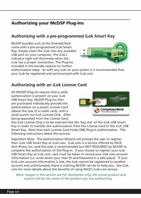
Authorizing with a pre-programmed iLok Smart Key
McDSP bundles such as the Emerald Pack come with a pre-programmed iLok Smart Key. Simply insert the iLok into any available USB port on your computer. The iLok’s indicator light will illuminate when the iLok has a proper connection. The Plug-Ins included in the bundle require no further authorization steps. As with any iLok on your system it is recommended that your iLok be registered and synchronized with iLok.com
Authorizing with an iLok License Card
All McDSP Plug-Ins require that a valid authorization is present on your iLok USB Smart Key. McDSP Plug-ins that are purchased individually provide this authorization on a plastic License Card (about the size of a credit card), with a small punch-out iLok License Chip. After being separated from the License Card, this iLok License Chip is to be inserted into the ‘key slot’ of the iLok USB Smart Key in order to transfer the authorization from the License Card to the iLok USB Smart Key. Note that each License Card holds ONE Plug-In authorization. The following instructions detail this process
Important Note: The Authorization Wizard will prompt the user to register their iLok USB Smart Key at iLok.com. iLok.com is a service offered by PACE Anti-Piracy, Inc. and this step is recommended but NOT REQUIRED by McDSP to complete the authorization of the Plug-In. If you choose to register your iLok USB Smart Key at iLok.com, care must be taken to record your ilok.com account information (i.e. write down your User ID and Password in a safe place). If your iLok.com account information is lost, the iLok cannot be registered to another account and unfortunately there is nothing McDSP can do to help you. See iLok.com for more details about the benefits of using PACE’s iLok.com service.
Note: Images in this section are for illustration only, the actual product and screens will be the name of the product you are authorizing.

mcdsp.com Page xvii
Authorizing Your McDSP Plug-Ins
Authorizing a McDSP Plug-In from a License Card with the Authorization Wizard:
The Authorization Wizard is used to install an authorization from a License Card to the iLok USB Smart Key. To use the Authorization Wizard for the Plug-In you purchase, perform the following steps:
• Insert your iLok USB Smart Key into an available USB port.
• On a Mac :Locate and launch the ‘Authorizer’ application found in the ‘Authorize’ folder in the Plug-In package for the McDSP Plug-In you purchased on the CD-ROM.
• On Windows XP or Vista, just launch Pro Tools™ to authorize the individual McDSP Plug-In you purchased.
Note: When authorizing the Plug-In on Windows XP or Vista with a new iLok USB Smart Key, you must insert the iLok USB Smart Key and complete the Windows ‘Found New Hardware Wizard’ before attempting to authorize the Plug-In.
• Select the ‘Authorize’ button to be guided through the Authorization Wizard.
Note: Selecting the ‘Quit’ button at any time will not authorize the Plug-In or allow it to be used for a trial period. If ‘Quit’ is selected, the Plug-In will not be available in the Pro Tools™ insert menu.
• McDSP Plug-Ins require that the user personalize their copy of the Plug-In. A dialog is displayed soliciting this information.
Note that the product registration card enclosed with the Plug-In MUST ALSO be filled out as well and returned to McDSP via mail (or fax to 707-220-0994). This additional mail-in registration will entitle the user to future upgrades and advance information from McDSP.

Page xviii
• Once the Plug-In is personalized, click the ‘Next’ button to continue.
• Check the ‘Use License Card’ box and press the ‘Next’ button (figure 2.3).
Note: Although the Authorization Wizard may appear to allow authorization by challenge/response, that method is currently NOT SUPPORTED McDSP Plug-Ins.
• Separate the small punch-out iLok License Chip (the removable metal and plastic tab) from the License Card by pushing the cutout up and out with your thumb. Do not force your finger downward.
• The iLok License Chip may now be inserted into the ‘key slot’ of the iLok USB Smart Key (figure 2.6). If the iLok USB Smart Key does not appear to be present on the system, ensure the iLok USB Smart Key is connected to a valid USB port and that the green LED is lit inside the iLok USB Smart Key. To insert the License Chip into the iLok USB Smart Key, orient the iLok USB Smart Key’s USB end to the left, and the loop end to the upper right. Insert the metal chip end of the iLok License Chip (the License Chip tab should have the metal chip side facing up towards you, not down). You should be able to visually verify that the License Chip makes contact with the iLok USB Smart Key metal card reader.
• The green LED in the iLok USB Smart Key will light when it is ready to receive and transmit data.
• Upon inserting the iLok License Chip, a message will be displayed indicating the authorization was installed successfully. Click ‘Ok’ in the message dialog.
mcdsp.com Page xix
Authorizing Your McDSP Plug-Ins
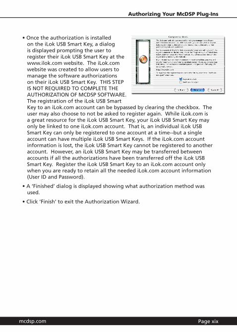
• Once the authorization is installed on the iLok USB Smart Key, a dialog is displayed prompting the user to register their iLok USB Smart Key at the www.ilok.com website. The iLok.com website was created to allow users to manage the software authorizations on their iLok USB Smart Key. THIS STEP IS NOT REQUIRED TO COMPLETE THE AUTHORIZATION OF MCDSP SOFTWARE. The registration of the iLok USB Smart Key to an iLok.com account can be bypassed by clearing the checkbox. The user may also choose to not be asked to register again. While iLok.com is a great resource for the iLok USB Smart Key, your iLok USB Smart Key may only be linked to one iLok.com account. That is, an individual iLok USB Smart Key can only be registered to one account at a time--but a single account can have multiple iLok USB Smart Keys. If the iLok.com account information is lost, the iLok USB Smart Key cannot be registered to another account. However, an iLok USB Smart Key may be transferred between accounts if all the authorizations have been transferred off the iLok USB Smart Key. Register the iLok USB Smart Key to an iLok.com account only when you are ready to retain all the needed iLok.com account information (User ID and Password).
• A ‘Finished’ dialog is displayed showing what authorization method was used.
• Click ‘Finish’ to exit the Authorization Wizard.

Page xx
Authorizing with iLok.com
Required for demo, upgrade, and replacement authorizations only
iLok.com can be accessed from any Macintosh or PC with an Internet connection. You can do this at home, a friend’s, or at the office as long as there is an internet connection to access iLok.com--note that you don’t have to use your ProTools system computer! You simply use this computer to connect to iLok.com and transfer authorizations to your iLok Smart Key. The iLok Smart Key can then be moved to your ProTools system to complete authorization of your Plug-In.
You will need:
• A computer with an Internet connection. Either a Macintosh running OS 9.2 to OS 10.3 or a PC running Windows 98, ME, 2000, XP, or Vista
• An iLok USB Smart Key
• A valid iLok.com account. Visit www.iLok.com and set up a free account, if you have not already done so.
1) Download and install the required client software from iLok.com.
2) Download the desired McDSP Plug-In Installer from: http://www.mcdsp.com/support/updating.html
3) To receive an upgrade or replacement authorization, send email your iLok.com account information to: [email protected] To receive a demo authorization, email your iLok.com account information to: [email protected]
Insert your iLok Smart Key into an available USB port and ensure that the indicator light is lit. Once your demo, upgrade, or replacement authorization is available for transfer, your iLok.com account will display the notice saying “You have licenses” on the upper left. Begin by selecting that link.
mcdsp.com Page xxi
Authorizing Your McDSP Plug-Ins
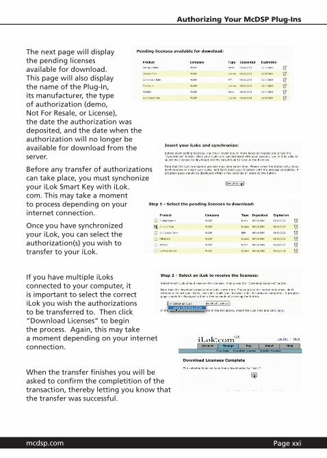
The next page will display the pending licenses available for download. This page will also display the name of the Plug-In, its manufacturer, the type of authorization (demo, Not For Resale, or License), the date the authorization was deposited, and the date when the authorization will no longer be available for download from the server.
Before any transfer of authorizations can take place, you must synchonize your iLok Smart Key with iLok.com. This may take a moment to process depending on your internet connection.
Once you have synchronized your iLok, you can select the authorization(s) you wish to transfer to your iLok.
If you have multiple iLoks connected to your computer, it is important to select the correct iLok you wish the authorizations to be transferred to. Then click “Download Licenses” to begin the process. Again, this may take a moment depending on your internet connection.
When the transfer finishes you will be asked to confirm the completition of the transaction, thereby letting you know that the transfer was successful.
Page xxii
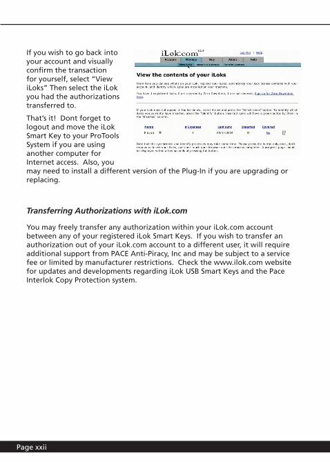
If you wish to go back into your account and visually confirm the transaction for yourself, select “View iLoks” Then select the iLok you had the authorizations transferred to.
That’s it! Dont forget to logout and move the iLok Smart Key to your ProTools System if you are using another computer for Internet access. Also, you may need to install a different version of the Plug-In if you are upgrading or replacing.
Transferring Authorizations with iLok.com
You may freely transfer any authorization within your iLok.com account between any of your registered iLok Smart Keys. If you wish to transfer an authorization out of your iLok.com account to a different user, it will require additional support from PACE Anti-Piracy, Inc and may be subject to a service fee or limited by manufacturer restrictions. Check the www.ilok.com website for updates and developments regarding iLok USB Smart Keys and the Pace Interlok Copy Protection system.
mcdsp.com Page xxiii
Authorizing Your McDSP Plug-Ins
Registering your McDSP Plug-In
To register your McDSP Plug-In, fill out and return the product registration card enclosed with the boxed Plug-In package by mail or fax 707-220-0994. Registering your product entitles you to future upgrades and advance information from McDSP. Each individual product must be registered (even if you have multiple copies), and the product must be registered to an individual, not an entity. If you represent a company it is your company’s responsibility to notify McDSP in writing if the individual who registered the Plug-In is no longer with the company. The Company must also be able to supply matching registration information to successfully transfer ownership of the Plug-In.
Using your McDSP Plug-Ins
Starting a McDSP Plug-In:
Follow the installation, authorization, and registration instructions above, Launch Pro Tools™, and the McDSP Plug-In and its presets are ready for use. Refer to the Digidesign™ Pro Tools™ Reference Guide for details on general Plug-In operation such as automation.
Exiting a McDSP Plug-In
A McDSP Plug-In is exited by clicking on the desktop or other window in the DAE application running the Plug-In, closing the Plug-In window, or de-instantiating the Plug-In. Pro Tools™ sessions will save instantiated Plug-In configurations and their settings. Refer to the Digidesign™ Pro Tools™ Reference Guide for details on general Plug-In operation.
Digidesign™ and Pro Tools™ are registered trademarks of Digidesign, Inc.
mcdsp.com Page 1
McDSP Analog Channel
Analog Channel
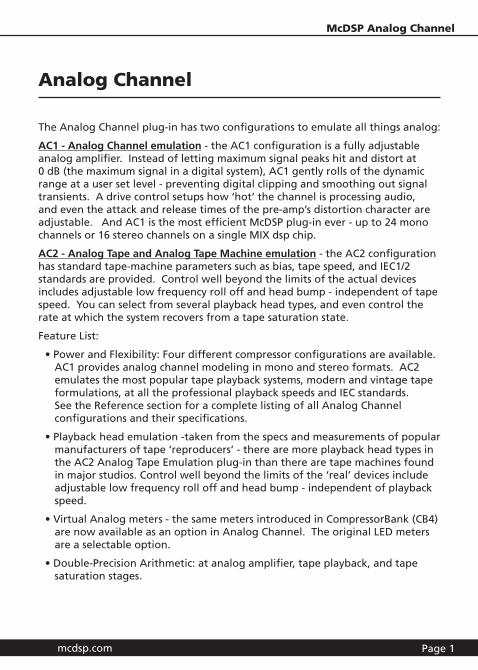
The Analog Channel plug-in has two configurations to emulate all things analog:
AC1 - Analog Channel emulation - the AC1 configuration is a fully adjustable analog amplifier. Instead of letting maximum signal peaks hit and distort at 0 dB (the maximum signal in a digital system), AC1 gently rolls of the dynamic range at a user set level - preventing digital clipping and smoothing out signal transients. A drive control setups how ‘hot’ the channel is processing audio, and even the attack and release times of the pre-amp’s distortion character are adjustable. And AC1 is the most efficient McDSP plug-in ever - up to 24 mono channels or 16 stereo channels on a single MIX dsp chip.
AC2 - Analog Tape and Analog Tape Machine emulation - the AC2 configuration has standard tape-machine parameters such as bias, tape speed, and IEC1/2 standards are provided. Control well beyond the limits of the actual devices includes adjustable low frequency roll off and head bump - independent of tape speed. You can select from several playback head types, and even control the rate at which the system recovers from a tape saturation state.
Feature List:
• Power and Flexibility: Four different compressor configurations are available. AC1 provides analog channel modeling in mono and stereo formats. AC2 emulates the most popular tape playback systems, modern and vintage tape formulations, at all the professional playback speeds and IEC standards. See the Reference section for a complete listing of all Analog Channel configurations and their specifications.
• Playback head emulation -taken from the specs and measurements of popular manufacturers of tape ‘reproducers’ - there are more playback head types in the AC2 Analog Tape Emulation plug-in than there are tape machines found in major studios. Control well beyond the limits of the ‘real’ devices include adjustable low frequency roll off and head bump - independent of playback speed.
• Virtual Analog meters - the same meters introduced in CompressorBank (CB4) are now available as an option in Analog Channel. The original LED meters are a selectable option.
• Double-Precision Arithmetic: at analog amplifier, tape playback, and tape saturation stages.
Page 2
• Analog Saturation Modeling: at tape playback head and tape saturation stages.
• Performance: On Pro Tools™ HD systems, the TDM version of Analog Channel can run up to 28 mono (or 18 stereo) analog channels (AC1), and up to 8 mono (or 4 stereo) analog tape machines (AC2), at 48 kHz sampling rate. On ProTools HD systems, 96 kHz and 192 kHz sample rates are also supported. On HD Accel systems, Analog Channel can get up to 2 times (2x) the number of channels as on HD systems. Other dsp performance specifications are detailed in the Reference Section at the end of this chapter.
• Analog Channel is compatible with ProTools and other DAW applications that support TDM, RTAS, and Audiosuite plug-in formats. The McDSP Analog Channel plug-in operates on Mac OS X and Windows XP systems.
Attention Analog Channel LE owners:
This manual contains a description of the full Analog Channel plug-in. Analog Channel LE contains the Tape Head control from the AC2 configuration of the full Analog Channel plug-in. For more information on Analog Channel LE, see the printed quick start guide included with the plug-in. For information on upgrading to the full version of Analog Channel, see www.mcdsp.com
Digidesign™ and Pro Tools™ are registered trademarks of Digidesign, Inc. All other trademarks are property of their respective owners.
mcdsp.com Page 3
McDSP Analog Channel
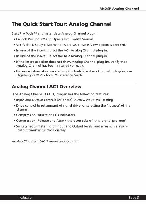
The Quick Start Tour: Analog Channel
Start Pro Tools™ and Instantiate Analog Channel plug-in
• Launch Pro Tools™ and Open a Pro Tools™ Session.
• Verify the Display-> Mix Window Shows->Inserts View option is checked.
• In one of the inserts, select the AC1 Analog Channel plug-in.
• In one of the inserts, select the AC2 Analog Channel plug-in.
• If the insert selection does not show Analog Channel plug-ins, verify that Analog Channel has been installed correctly.
• For more information on starting Pro Tools™ and working with plug-ins, see Digidesign’s ™ Pro Tools™ Reference Guide
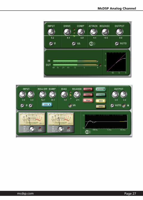
Analog Channel AC1 Overview
The Analog Channel 1 (AC1) plug-in has the following features:
• Input and Output controls (w/ phase), Auto Output level setting
• Drive control to set amount of signal drive, or selecting the ‘hotness’ of the channel
• Compression/Saturation LED indicators
• Compression, Release and Attack characteristics of this ‘digital pre-amp’
• Simultaneous metering of Input and Output levels, and a real-time Input-Output transfer function display
Analog Channel 1 (AC1) mono configuration
Page 4
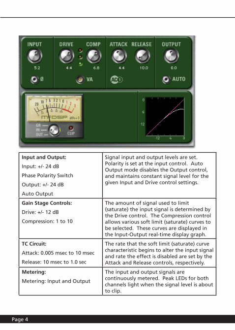
Input and Output:
Input: +/- 24 dB
Phase Polarity Switch
Output: +/- 24 dB
Auto Output
Signal input and output levels are set. Polarity is set at the input control. Auto Output mode disables the Output control, and maintains constant signal level for the given Input and Drive control settings.
Gain Stage Controls:
Drive: +/- 12 dB
Compression: 1 to 10
The amount of signal used to limit (saturate) the input signal is determined by the Drive control. The Compression control allows various soft limit (saturate) curves to be selected. These curves are displayed in the Input-Output real-time display graph.
TC Circuit:
Attack: 0.005 msec to 10 msec
Release: 10 msec to 1.0 sec
The rate that the soft limit (saturate) curve characteristic begins to alter the input signal and rate the effect is disabled are set by the Attack and Release controls, respectively.
Metering:
Metering: Input and Output
The input and output signals are continuously metered. Peak LEDs for both channels light when the signal level is about to clip.
mcdsp.com Page 5
McDSP Analog Channel
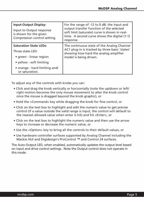
Input-Output Display:
Input to Output response is shown for the given Compression control setting.
For the range of -12 to 0 dB, the input and output transfer function of the selected soft limit (saturate) curve is shown in real-time. A second curve shows the digital (1:1) response.
Saturation State LEDs:
Three state LED:
• green - linear region
• yellow - soft limiting
• orange - hard limiting and/or saturation.
The continuous state of the Analog Channel AC1 plug-in is tracked by three basic ‘states’ showing how hard the analog amplifier model is being driven.
To adjust any of the controls with knobs you can:
• Click and drag the knob vertically or horizontally (note the up/down or left/right motion becomes the only mouse movement to alter the knob control once the mouse is dragged beyond the knob graphic), or
• Hold the <Command> key while dragging the knob for fine control, or
• Click on the text box to highlight and edit the numeric value to get precise control (if a value outside the valid range is input, the control will default to the nearest allowed value when enter is hit) and hit <Enter>, or
• Click on the text box to highlight the numeric value and then use the arrow keys to increase or decrease the numeric value, or
• Use the <Option> key to bring all the controls to their default values, or
• Use hardware controller surfaces supported by Analog Channel including the Mackie HUI and Digidesign’s ProControl ™ and Control 24 surfaces.
The Auto Output LED, when enabled, automatically updates the output level based on input and drive control settings. Note the Output control does not operate in this mode.
Page 6
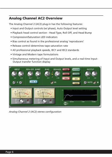
Analog Channel AC2 Overview
The Analog Channel 2 (AC2) plug-in has the following features:
• Input and Output controls (w/ phase), Auto Output level setting
• Playback head control section - Head Type, Roll Off, and Head Bump
• Compression/Saturation LED indicators
• Bias control as found in the professional analog ‘reproducers’
• Release control determines tape saturation rate
• All professional playback speeds, IEC1 and IEC2 standards
• Vintage and Modern tape formulations
• Simultaneous metering of Input and Output levels, and a real-time Input-Output transfer function display
Analog Channel 2 (AC2) stereo configuration
mcdsp.com Page 7
McDSP Analog Channel
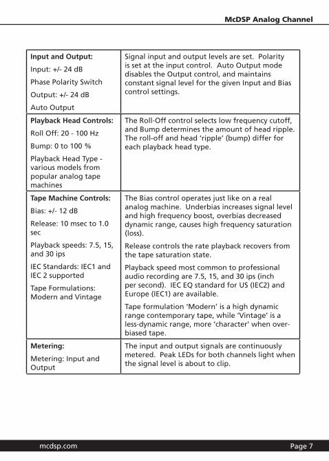
Input and Output:
Input: +/- 24 dB
Phase Polarity Switch
Output: +/- 24 dB
Auto Output
Signal input and output levels are set. Polarity is set at the input control. Auto Output mode disables the Output control, and maintains constant signal level for the given Input and Bias control settings.
Playback Head Controls:
Roll Off: 20 - 100 Hz
Bump: 0 to 100 %
Playback Head Type - various models from popular analog tape machines
The Roll-Off control selects low frequency cutoff, and Bump determines the amount of head ripple. The roll-off and head ‘ripple’ (bump) differ for each playback head type.
Tape Machine Controls:
Bias: +/- 12 dB
Release: 10 msec to 1.0 sec
Playback speeds: 7.5, 15, and 30 ips
IEC Standards: IEC1 and IEC 2 supported
Tape Formulations: Modern and Vintage
The Bias control operates just like on a real analog machine. Underbias increases signal level and high frequency boost, overbias decreased dynamic range, causes high frequency saturation (loss).
Release controls the rate playback recovers from the tape saturation state.
Playback speed most common to professional audio recording are 7.5, 15, and 30 ips (inch per second). IEC EQ standard for US (IEC2) and Europe (IEC1) are available.
Tape formulation ‘Modern’ is a high dynamic range contemporary tape, while ‘Vintage’ is a less-dynamic range, more ‘character’ when over-biased tape.
Metering:
Metering: Input and Output
The input and output signals are continuously metered. Peak LEDs for both channels light when the signal level is about to clip.
Page 8
General Information
Basics
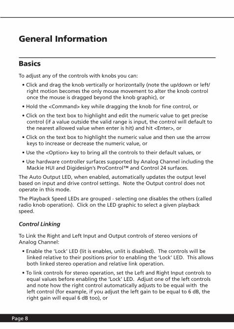
To adjust any of the controls with knobs you can:
• Click and drag the knob vertically or horizontally (note the up/down or left/right motion becomes the only mouse movement to alter the knob control once the mouse is dragged beyond the knob graphic), or
• Hold the <Command> key while dragging the knob for fine control, or
• Click on the text box to highlight and edit the numeric value to get precise control (if a value outside the valid range is input, the control will default to the nearest allowed value when enter is hit) and hit <Enter>, or
• Click on the text box to highlight the numeric value and then use the arrow keys to increase or decrease the numeric value, or
• Use the <Option> key to bring all the controls to their default values, or
• Use hardware controller surfaces supported by Analog Channel including the Mackie HUI and Digidesign’s ProControl™ and Control 24 surfaces.
The Auto Output LED, when enabled, automatically updates the output level based on input and drive control settings. Note the Output control does not operate in this mode.
The Playback Speed LEDs are grouped - selecting one disables the others (called radio knob operation). Click on the LED graphic to select a given playback speed.
Control Linking
To Link the Right and Left Input and Output controls of stereo versions of Analog Channel:
• Enable the ‘Lock’ LED (lit is enables, unlit is disabled). The controls will be linked relative to their positions prior to enabling the ‘Lock’ LED. This allows both linked stereo operation and relative link operation.
• To link controls for stereo operation, set the Left and Right Input controls to equal values before enabling the ‘Lock’ LED. Adjust one of the left controls and note how the right control automatically adjusts to be equal with the left control (for example, if you adjust the left gain to be equal to 6 dB, the right gain will equal 6 dB too), or
mcdsp.com Page 9
McDSP Analog Channel
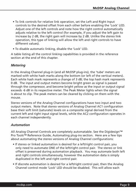
• To link controls for relative link operation, set the Left and Right Input controls to the desired offset from each other before enabling the ‘Lock’ LED. Adjust one of the left controls and note how the right control automatically adjusts relative to the left control (for example, if you adjust the left gain to increase by 2 dB, the right gain will increase by 2 dB. Unlike the stereo link operation, this type of linking will allow the left and right controls to have different values).
• To disable automatic linking, disable the ‘Lock’ LED.
A table listing all the control linking capabilities is provided in the reference section at the end of this chapter.
Metering
In the Analog Channel plug-in (and all McDSP plug-ins), the ‘tube’ meters are marked with white hash marks along the bottom (or left of the vertical meters). Each white hash mark represents a change of 3 dB; the top hash mark represents 0 dB. The input and output meters become bright green as signal is passed through the compressor, and become bright yellow as the input or output signal exceeds -6 dB in its respective meter. The Peak Meter lights when the signal is about to clip. The peak meters can be cleared by clicking on them with the mouse.
Stereo versions of the Analog Channel configurations have two input and two output meters. Note that stereo versions of Analog Channel AC1 configuration base their soft limit (saturate) levels on a composite signal derived from the current left and right input signal levels, while the AC2 configuration operates in each channel independently.
Automation
All Analog Channel Controls are completely automatable. See the Digidesign™ Pro Tools™ Reference Guide, Automating plug-ins section. Here are a few tips about automating the stereo versions of Analog Channel configurations:
• If stereo or linked automation is desired for a left/right control pair, you only need to automate ONE of the left/right control pair. The stereo or link offset is preserved during automation playback. You may automate both left and right controls simultaneously, however the automation data is simply duplicated in the left and right control pair.
• If discrete automation is desired for a left/right control pair, then the Analog Channel control mode ‘Lock’ LED should be disabled. This will allow each
Page 10
left/right control to operate independently, and not also send automation events to each other as is the case when the Analog Channel ‘Lock’ LED is enabled.
Presets: Using the Presets and Making Your Own
The Analog Channel presets are inspired by various tape machines made from manufacturers such as Studer, Otari, MCI, Ampex, Sony, and Tascam. A variety of other presets are named for their application (‘vocal’, ‘drums’, ‘guitar’) are also available. The presets can be accessed from the Pro Tools™ “plug-in Librarian” and “plug-in Settings” pop-up menus.
To make and save your own presets, see the “plug-in Librarian Functions” section of Digidesign™‘s DigiRack plug-ins Guide.
A Word on Preset Compatibility: Presets for the AC1 and AC2 configurations are NOT interchangeable. For more information, see Chapter 4: Modeling Analog Tape Machines.
*All Trademarks are property of their respective owners. Studer, Otari, MCI, Ampex, Sony, and Tascam are all trademarks of their respective companies. These companies are not affiliated in any way with McDSP, nor do they endorse the Analog Channel plug-in. The trademarks of these companies are used solely for the purpose of describing the sounds produced by the McDSP Analog Channel plug-in.
Pro Tools™ is a registered trademark of Digidesign, Inc.
mcdsp.com Page 11
McDSP Analog Channel
Using the AC1 Plug-In
The Analog Channel Emulator AC1 plug-in is an analog amplifier, or analog channel. Instead of allowing the user to drive signal levels into digital clipping at 0 dB, the AC1 plug-in provides gentle, continuous soft-limiting/compression (or saturation pending the attack/release times), at a signal level selected by the user. AC1 can be used as a fail-safe for preventing unwanted clipping, or as a creative tool to smooth/warm-up digital tracks and provide otherwise unavailable analog character to a digital system. Even the sound of large analog mixing consoles can be closely matched using the AC1 plug-in.
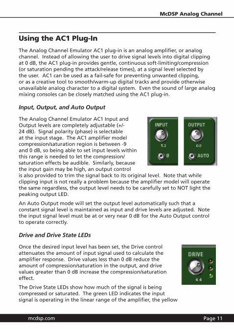
Input, Output, and Auto Output
The Analog Channel Emulator AC1 Input and Output levels are completely adjustable (+/- 24 dB). Signal polarity (phase) is selectable at the input stage. The AC1 amplifier model compression/saturation region is between -9 and 0 dB, so being able to set input levels within this range is needed to let the compression/saturation effects be audible. Similarly, because the input gain may be high, an output control is also provided to trim the signal back to its original level. Note that while clipping input is not really a problem because the amplifier model will operate the same regardless, the output level needs to be carefully set to NOT light the peaking output LED.
An Auto Output mode will set the output level automatically such that a constant signal level is maintained as input and drive levels are adjusted. Note the input signal level must be at or very near 0 dB for the Auto Output control to operate correctly.
Drive and Drive State LEDs
Once the desired input level has been set, the Drive control attenuates the amount of input signal used to calculate the amplifier response. Drive values less than 0 dB reduce the amount of compression/saturation in the output, and drive values greater than 0 dB increase the compression/saturation effect.
The Drive State LEDs show how much of the signal is being compressed or saturated. The green LED indicates the input signal is operating in the linear range of the amplifier, the yellow
Page 12
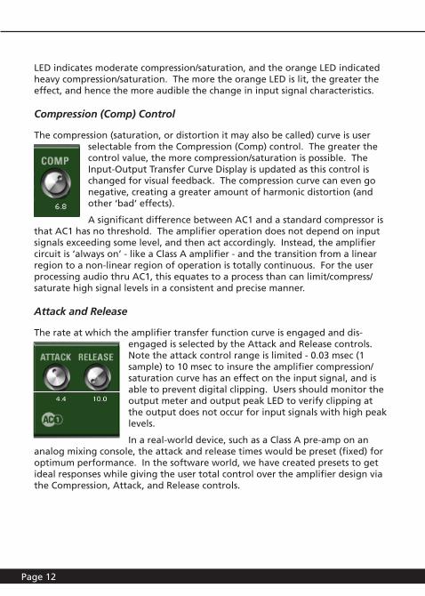
LED indicates moderate compression/saturation, and the orange LED indicated heavy compression/saturation. The more the orange LED is lit, the greater the effect, and hence the more audible the change in input signal characteristics.
Compression (Comp) Control
The compression (saturation, or distortion it may also be called) curve is user selectable from the Compression (Comp) control. The greater the control value, the more compression/saturation is possible. The Input-Output Transfer Curve Display is updated as this control is changed for visual feedback. The compression curve can even go negative, creating a greater amount of harmonic distortion (and other ‘bad’ effects).
A significant difference between AC1 and a standard compressor is that AC1 has no threshold. The amplifier operation does not depend on input signals exceeding some level, and then act accordingly. Instead, the amplifier circuit is ‘always on’ - like a Class A amplifier - and the transition from a linear region to a non-linear region of operation is totally continuous. For the user processing audio thru AC1, this equates to a process than can limit/compress/saturate high signal levels in a consistent and precise manner.
Attack and Release
The rate at which the amplifier transfer function curve is engaged and dis-engaged is selected by the Attack and Release controls. Note the attack control range is limited - 0.03 msec (1 sample) to 10 msec to insure the amplifier compression/saturation curve has an effect on the input signal, and is able to prevent digital clipping. Users should monitor the output meter and output peak LED to verify clipping at the output does not occur for input signals with high peak levels.
In a real-world device, such as a Class A pre-amp on an analog mixing console, the attack and release times would be preset (fixed) for optimum performance. In the software world, we have created presets to get ideal responses while giving the user total control over the amplifier design via the Compression, Attack, and Release controls.
mcdsp.com Page 13
McDSP Analog Channel
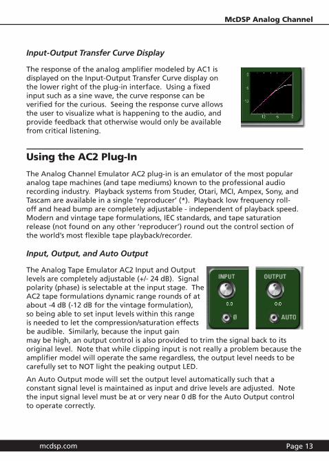
Input-Output Transfer Curve Display
The response of the analog amplifier modeled by AC1 is displayed on the Input-Output Transfer Curve display on the lower right of the plug-in interface. Using a fixed input such as a sine wave, the curve response can be verified for the curious. Seeing the response curve allows the user to visualize what is happening to the audio, and provide feedback that otherwise would only be available from critical listening.
Using the AC2 Plug-In
The Analog Channel Emulator AC2 plug-in is an emulator of the most popular analog tape machines (and tape mediums) known to the professional audio recording industry. Playback systems from Studer, Otari, MCI, Ampex, Sony, and Tascam are available in a single ‘reproducer’ (*). Playback low frequency roll-off and head bump are completely adjustable - independent of playback speed. Modern and vintage tape formulations, IEC standards, and tape saturation release (not found on any other ‘reproducer’) round out the control section of the world’s most flexible tape playback/recorder.
Input, Output, and Auto Output
The Analog Tape Emulator AC2 Input and Output levels are completely adjustable (+/- 24 dB). Signal polarity (phase) is selectable at the input stage. The AC2 tape formulations dynamic range rounds of at about -4 dB (-12 dB for the vintage formulation), so being able to set input levels within this range is needed to let the compression/saturation effects be audible. Similarly, because the input gain may be high, an output control is also provided to trim the signal back to its original level. Note that while clipping input is not really a problem because the amplifier model will operate the same regardless, the output level needs to be carefully set to NOT light the peaking output LED.
An Auto Output mode will set the output level automatically such that a constant signal level is maintained as input and drive levels are adjusted. Note the input signal level must be at or very near 0 dB for the Auto Output control to operate correctly.
Page 14
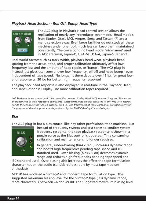
Playback Head Section - Roll Off, Bump, Head Type
The AC2 plug-in Playback Head control section allows the replication of nearly any ‘reproducer’ ever made. Head models from Studer, Otari, MCI, Ampex, Sony, and Tascam (*) are a menu selection away. Even large facilities do not stock all these machines under one roof, much less can keep them maintained consistently. The corresponding head model ‘nicknames’ used in AC2 are Swiss, Japan-O, USA-M, USA-A, Japan-S, Japan-T.
Real-world factors such as track width, playback head wear, playback head spacing from the actual tape, and proper calibration ultimately affect low frequency loss and the amount of heap ripple, or ‘bump’. The AC2 plug-in instead just gives user control over low frequency roll-off and head bump - even independent of tape speed. No longer is there debate over 15 ips for great low-end response vs. 30 ips for better high frequency response!
The playback head response is also displayed in real-time in the Playback Head and Tape Response Display - no more calibration tapes required.
*All Trademarks are property of their respective owners. Studer, Otari, MCI, Ampex, Sony, and Tascam are all trademarks of their respective companies. These companies are not affiliated in any way with McDSP, nor do they endorse the Analog Channel plug-in. The trademarks of these companies are used solely for the purpose of describing the sounds produced by the McDSP Analog Channel plug-in.
Bias
The AC2 plug-in has a bias control like nay other professional tape machine. But instead of frequency sweeps and test tones to confirm system frequency response, the tape playback response is shown in a purple curve as the Bias control is updated. Time consuming calibration and maintenance is no longer required.
In general, under-biasing (bias < 0 dB) increases dynamic range and boosts high frequencies pending tape speed and IEC standard used. Over-biasing (bias > 0 dB) decreases dynamic range and reduces high frequencies pending tape speed and
IEC standard used. Over-biasing also increases the effect the tape formulation character has on the audio (considered desirable by most tape medium enthusiasts).
McDSP has modeled a ‘vintage’ and ‘modern’ tape formulation type. The suggested maximum biasing level for the ‘vintage’ type (less dynamic range, more character) is between +6 and +9 dB. The suggested maximum biasing level
mcdsp.com Page 15
McDSP Analog Channel
for the modern type (less dynamic range, more character) is between +9 and +12 dB. The user can adjust the Bias control as desired, although some extreme over-biasing can occur if these maximums are exceeded.
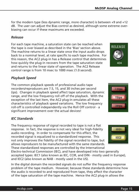
Release
For each tape machine, a saturation state can be reached when the tape is over biased as described in the ‘Bias’ section above. The machine returns to a linear state once the input audio drops back to a nominal level, at rate specific to each tape machine. For this reason, the AC2 plug-in has a Release control that determines how quickly the plug-in recovers from the tape saturation state and returns to the linear state of operation. The AC2 Release control range is from 10 msec to 1000 msec (1.0 second).
Playback Speed
The common playback speeds of professional audio tape recorders/reproducers are 7.5, 15, and 30 inches per second (ips). Changes in playback speed affect tape saturation, dynamic range, and the low frequency roll off of the playback. With the exception of the last item, the AC2 plug-in emulates all these characteristics of playback speed variations. The low frequency roll-off is controlled independently via the Roll Off control - a significant improvement over the actual devices!
IEC Standards
The frequency response of signal recorded to tape is not a flat response. In fact, the response is not very ideal for high-fidelity audio recording. In order to compensate for this effect, the recorded signal is equalized to a standardized response. This not only improves the fidelity of the signal recorded to tape, but allows reproducers to be manufactured with the same standards. These standardized responses are controlled by the International Electro-technical Commission (IEC), and have developed into two generally accepted types: IEC1 (also known as IEC, CCIR, and DIN - mostly used in Europe), and IEC2 (also known as NAB - mostly used in the US).
In the digital domain the recorded signals do not suffer the frequency response problem of the tape medium. However, because these standards determine how the audio is recorded to and reproduced from tape, they affect the character of the tape saturation of the tape machine. Hence the AC2 plug-in allows the
Page 16
selection of IEC1 or IEC2 equalization, and the subsequent sonic affects are displayed in the Tape Playback Head and Tape Response Display. Note how the purple saturation curve changes as the IEC1 or IEC2 standards are selected for the various tape speeds.
Tape Formulations
In the world of tape, not only does the tape machine influence how the audio is heard, the tape medium itself is also a sonic factor. A great number of tape formulations have been created since the tape machine was first developed. The AC2 plug-in has consolidated them all into two generally accepted formulation categories:
• Modern: current manufacturing technologies create a tape with a much greater dynamic range than earlier formulations. These tapes have a large linear region, and hence have a smaller non-linear (saturation) ‘character’. This makes for recordings as true as possible to the original material.
• Vintage: older tape mediums tend to have less dynamic range, and suffer from greater distortion/saturation. These tapes, however, have ‘character’ that newer ones do not, and have been used with great success in recording audio.
Tape Playback Head and Tape Response Display
A conventional tape machine (recorder or reproducer) requires a great deal of maintenance, to insure the unit performs consistently. This requirement is complicated by the subjective criteria of each user - the ‘optimal’ setup may differ from project to project.
Fortunately in the digital domain, the ‘good’ things about tape machines and the tape medium can be modeled, and the models can perform consistently over time. Additionally, the ‘optimal’ setup is only a few control changes away (instead of a tedious calibration session).
The rapid setup of the virtual tape machine in the AC2 plug-in is facilitated by the visual feedback of its controls and the Tape Playback Head and Tape Response Display.
The white curve shows the playback head response - low frequency roll-off and head bump levels update as the playback head type, Roll-off, and Bump controls on the AC2 plug-in are updated. The purple curve shows the amount of tape saturation caused by the under/over biasing of the virtual tape machine, and how the biasing changes for different playback speeds and
mcdsp.com Page 17
McDSP Analog Channel
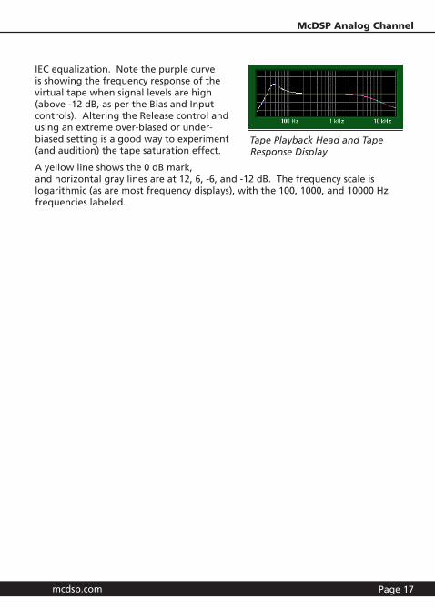
IEC equalization. Note the purple curve is showing the frequency response of the virtual tape when signal levels are high (above -12 dB, as per the Bias and Input controls). Altering the Release control and using an extreme over-biased or under-biased setting is a good way to experiment (and audition) the tape saturation effect.
A yellow line shows the 0 dB mark, and horizontal gray lines are at 12, 6, -6, and -12 dB. The frequency scale is logarithmic (as are most frequency displays), with the 100, 1000, and 10000 Hz frequencies labeled.
Tape Playback Head and Tape Response Display

Page 18
Modeling Analog Mixing Consoles with Analog Channel (AC1)
The Analog Channel plug-in models a wide variety of vintage and contemporary analog devices. Tape ‘reproducers’, Class A amplifiers, and even large analog mixing consoles can be emulated with the Analog Channel plug-in. This chapter highlights some of the modeling capabilities of Analog Channel. . The user is additionally directed to various presets included in the Analog Channel plug-in package.
The AC1 configuration is designed to emulate the characteristics of an analog amplifier stage. Many presets have been included with the Analog Channel plug-in to demonstrate the AC1 configuration abilities. Additionally, three ProTools sessions (no audio) have been created with an AC1 (mono) on every track of a 24-track mixer. An AC2 is placed on the stereo master fader. Some notes about using these session ‘templates’:
• The AC1 is placed in the first insert of each mixer channel.
• Signal level should be set by the Input control of the AC1 plug-in - leave the ProTools mixer fader at unity. The signal level can then be set without digital clipping, and the analog amplifier characteristics imparted to the mixer as well.
• The AC2 at the master fader is optional - just trying to give the total analog studio sound! Users may also want to experiment with an AC1 on the master fader
• Stereo tracks (not a part of these sessions) present an interesting (and subtle) application of the AC1 plug-in. The stereo channels can be processed together using a AC1 stereo config, or SEPERATELY (a multi-mono AC1 - PT 5.1 and later have this ability). Using a multi-mono AC1 on a stereo track can affect the ‘stereo character’ of the channel, and of the overall mix. Try it!
Modeling Analog Tape Machines with Analog Channel (AC2)
The AC2 configuration is designed to emulate the various aspects of ‘recording to tape’, including different tape machines and tape formulations, bias setups, tape speeds, and IEC EQ standards.
Each of the following sections contains graphs representing the frequency response of analog tape machines, as measured by the a third party engineer Jack Endino. Mr. Endino, having taken care over the course of his career to measure the responses of tape machines he has used, has been kind enough to share some of his data with McDSP engineering.
mcdsp.com Page 19
McDSP Analog Channel
The Analog Channel presets are inspired by tape machines manufactured from companies such as Studer, Ampex, MCI, Sony, Otari, and Tascam (*). The presets can be accessed from the Pro Tools™ “plug-in Librarian” and “plug-in Settings” pop-up menus.
To make and save your own presets, see the “plug-in Librarian Functions” section of Digidesign™‘s DigiRack plug-ins Guide.
*All Trademarks are property of their respective owners. Studer, Otari, MCI, Ampex, Sony, and Tascam are all trademarks of their respective companies. These companies are not affiliated in any way with McDSP, nor do they endorse the Analog Channel plug-in. The trademarks of these companies are used solely for the purpose of describing the sounds produced by the McDSP Analog Channel plug-in.
While Analog Channel emulates the sounds of these tape machines, McDSP makes no representation or warranty that Analog Channel is identical to or duplicates these devices.
Ampex MM 1200
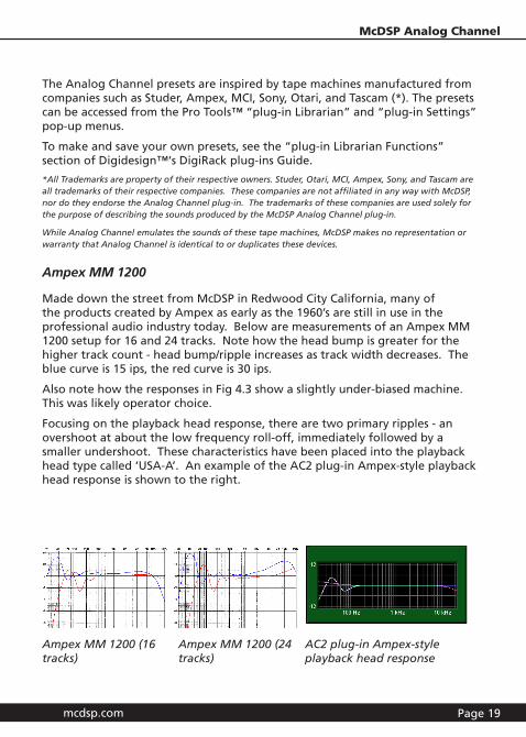
Made down the street from McDSP in Redwood City California, many of the products created by Ampex as early as the 1960’s are still in use in the professional audio industry today. Below are measurements of an Ampex MM 1200 setup for 16 and 24 tracks. Note how the head bump is greater for the higher track count - head bump/ripple increases as track width decreases. The blue curve is 15 ips, the red curve is 30 ips.
Also note how the responses in Fig 4.3 show a slightly under-biased machine. This was likely operator choice.
Focusing on the playback head response, there are two primary ripples - an overshoot at about the low frequency roll-off, immediately followed by a smaller undershoot. These characteristics have been placed into the playback head type called ‘USA-A’. An example of the AC2 plug-in Ampex-style playback head response is shown to the right.
Ampex MM 1200 (16 tracks)
Ampex MM 1200 (24 tracks)
AC2 plug-in Ampex-style playback head response
Page 20
Studer A80 mkII
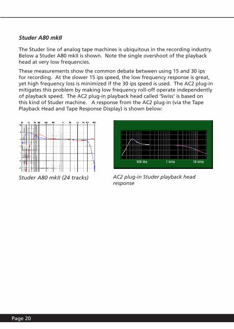
The Studer line of analog tape machines is ubiquitous in the recording industry. Below a Studer A80 mkII is shown. Note the single overshoot of the playback head at very low frequencies.
These measurements show the common debate between using 15 and 30 ips for recording. At the slower 15 ips speed, the low frequency response is great, yet high frequency loss is minimized if the 30 ips speed is used. The AC2 plug-in mitigates this problem by making low frequency roll-off operate independently of playback speed. The AC2 plug-in playback head called ‘Swiss’ is based on this kind of Studer machine. A response from the AC2 plug-in (via the Tape Playback Head and Tape Response Display) is shown below:
Studer A80 mkII (24 tracks) AC2 plug-in Studer playback head response

mcdsp.com Page 21
McDSP Analog Channel
Otari MX-80
The Otari analog tape machines were the work-horse of many facilities. Below measurements of a MX-80 at 15 ips (blue) and 30 ips (red) are shown, as well as a MX-5050 Mk III half-inch 8-track. Note the high frequency boost, possibly indicating the machine was slightly underbiased.
The Otari playback head responses are interesting in that they are somewhat flat just above its low frequency roll-off, and then have an over and under-shoot ripple. The AC2 plug-in playback head called ‘Japan-O’ is based on the Otari MX-80 and Otari MX-5050 Mk III half-inch 8-track.
Otari MX-80 (24 tracks)
AC2 plug-in Otari playback head response
Otari MX-5050 Mk III (8 tracks)
Page 22
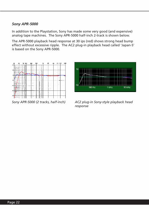
Sony APR-5000
In addition to the Playstation, Sony has made some very good (and expensive) analog tape machines. The Sony APR-5000 half-inch 2-track is shown below.
The APR-5000 playback head response at 30 ips (red) shows strong head bump effect without excessive ripple. The AC2 plug-in playback head called ‘Japan-S’ is based on the Sony APR-5000.
AC2 plug-in Sony-style playback head response
Sony APR-5000 (2 tracks, half-inch)
mcdsp.com Page 23
McDSP Analog Channel
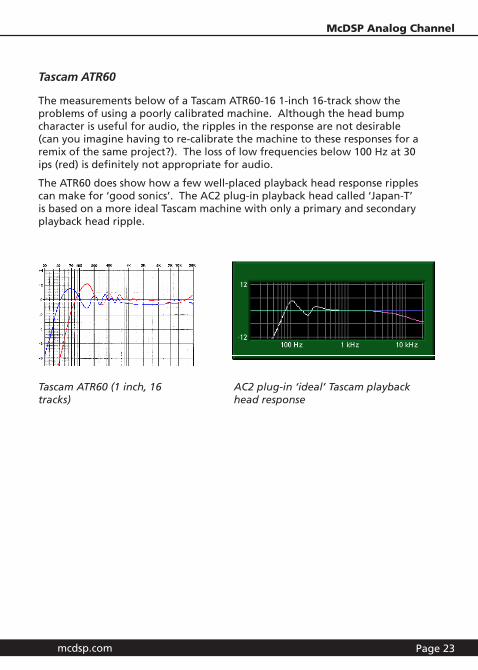
Tascam ATR60
The measurements below of a Tascam ATR60-16 1-inch 16-track show the problems of using a poorly calibrated machine. Although the head bump character is useful for audio, the ripples in the response are not desirable (can you imagine having to re-calibrate the machine to these responses for a remix of the same project?). The loss of low frequencies below 100 Hz at 30 ips (red) is definitely not appropriate for audio.
The ATR60 does show how a few well-placed playback head response ripples can make for ‘good sonics’. The AC2 plug-in playback head called ‘Japan-T’ is based on a more ideal Tascam machine with only a primary and secondary playback head ripple.
Tascam ATR60 (1 inch, 16 tracks)
AC2 plug-in ‘ideal’ Tascam playback head response

Page 24
Other Analog Channel Presets
Several other presets have been included in your Analog Channel plug-in package. These settings were created to highlight the flexibility and utility of Analog Channel. The AC1 analog channel emulator presets can be used to smooth a track or entire mix, and even be pressed into service as a gentle bus compressor/limiter. The AC2 analog tape machine emulator presets bring the sound of tape to the digital domain - great for sweetening drum, vocal, and bass tracks, and of course the entire mix!
Analog Channel is the most flexible analog emulator on the planet. We hope you enjoy using it as much as we did creating it!
mcdsp.com Page 25
McDSP Analog Channel
Analog Channel Plug-In Reference Guide
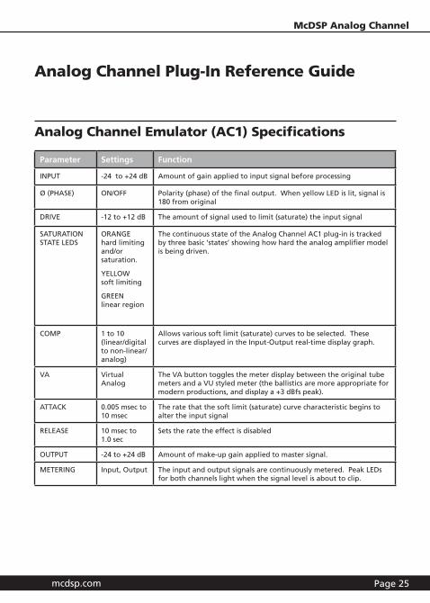
Analog Channel Emulator (AC1) Specifications
Parameter Settings Function
INPUT -24 to +24 dB Amount of gain applied to input signal before processing
ø (PHASE) ON/OFF Polarity (phase) of the final output. When yellow LED is lit, signal is 180 from original
DRIVE -12 to +12 dB The amount of signal used to limit (saturate) the input signal
SATURATION STATE LEDS
ORANGE hard limiting and/or saturation.
YELLOW soft limiting
GREEN linear region
The continuous state of the Analog Channel AC1 plug-in is tracked by three basic ‘states’ showing how hard the analog amplifier model is being driven.
COMP 1 to 10 (linear/digital to non-linear/analog)
Allows various soft limit (saturate) curves to be selected. These curves are displayed in the Input-Output real-time display graph.
VA Virtual Analog
The VA button toggles the meter display between the original tube meters and a VU styled meter (the ballistics are more appropriate for modern productions, and display a +3 dBfs peak).
ATTACK 0.005 msec to 10 msec
The rate that the soft limit (saturate) curve characteristic begins to alter the input signal
RELEASE 10 msec to 1.0 sec
Sets the rate the effect is disabled
OUTPUT -24 to +24 dB Amount of make-up gain applied to master signal.
METERING Input, Output The input and output signals are continuously metered. Peak LEDs for both channels light when the signal level is about to clip.
Page 26
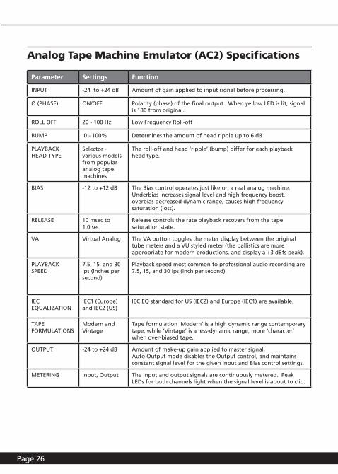
Analog Tape Machine Emulator (AC2) Specifications
Parameter Settings Function
INPUT -24 to +24 dB Amount of gain applied to input signal before processing.
ø (PHASE) ON/OFF Polarity (phase) of the final output. When yellow LED is lit, signal is 180 from original.
ROLL OFF 20 - 100 Hz Low Frequency Roll-off
BUMP 0 - 100% Determines the amount of head ripple up to 6 dB
PLAYBACK HEAD TYPE
Selector - various models from popular analog tape machines
The roll-off and head ‘ripple’ (bump) differ for each playback head type.
BIAS -12 to +12 dB The Bias control operates just like on a real analog machine. Underbias increases signal level and high frequency boost, overbias decreased dynamic range, causes high frequency saturation (loss).
RELEASE 10 msec to 1.0 sec
Release controls the rate playback recovers from the tape saturation state.
VA Virtual Analog The VA button toggles the meter display between the original tube meters and a VU styled meter (the ballistics are more appropriate for modern productions, and display a +3 dBfs peak).
PLAYBACK SPEED
7.5, 15, and 30 ips (inches per second)
Playback speed most common to professional audio recording are 7.5, 15, and 30 ips (inch per second).
IEC EQUALIZATION
IEC1 (Europe) and IEC2 (US)
IEC EQ standard for US (IEC2) and Europe (IEC1) are available.
TAPE FORMULATIONS
Modern and Vintage
Tape formulation ‘Modern’ is a high dynamic range contemporary tape, while ‘Vintage’ is a less-dynamic range, more ‘character’ when over-biased tape.
OUTPUT -24 to +24 dB Amount of make-up gain applied to master signal. Auto Output mode disables the Output control, and maintains constant signal level for the given Input and Bias control settings.
METERING Input, Output The input and output signals are continuously metered. Peak LEDs for both channels light when the signal level is about to clip.
mcdsp.com Page 27
McDSP Analog Channel
Page 28
Analog Channel Linked Control Table
Analog Channel provides a variety of linked control functionality in its many configurations. The table below lists all the linking capabilities as of the v1.0 version of Analog Channel. For more information on control linking, see the Control Linking section of the Quick Start Tour.
Linked Controls Link Action Link Type
Left/Right Input and Output controls
Enable the ‘Lock’ LED Absolute or Relative
Analog Channel DSP Delay
The delay incurred by any of the Analog Channel configurations is ZERO samples. The delay is 1 sample on HD systems. There is still a two sample delay from the TDM connection to/from the Analog Channel plug-in. This is the absolute minimum number of delay samples a TDM plug-in can have. The McDSP plug-ins are designed in this manner to provide the user with the closest analog mixing console experience possible (analog inserts such as EQ and compression do not cause a processing delay when inserted into a track).
mcdsp.com Page 29
McDSP Analog Channel
Analog Channel DSP Usage
HD and HD Accel DSP hardware
The TDM versions of the Analog Channel plug-in configurations use a varying amount of dsp resources for each Analog Channel configuration. The table below is a listing of these dsp usages. The DSP Allocator utility provided by Digidesign™ can be used to display dsp resource allocation when Pro Tools™ is running.
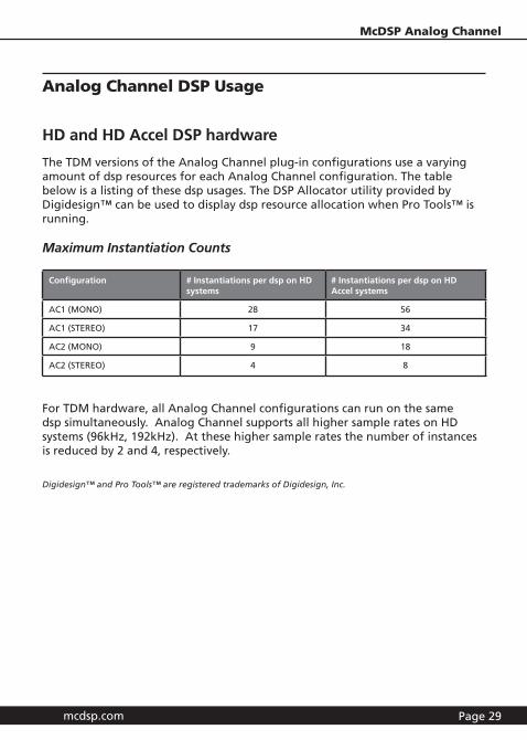
Maximum Instantiation Counts
Configuration # Instantiations per dsp on HD systems
# Instantiations per dsp on HD Accel systems
AC1 (MONO) 28 56
AC1 (STEREO) 17 34
AC2 (MONO) 9 18
AC2 (STEREO) 4 8
For TDM hardware, all Analog Channel configurations can run on the same dsp simultaneously. Analog Channel supports all higher sample rates on HD systems (96kHz, 192kHz). At these higher sample rates the number of instances is reduced by 2 and 4, respectively.
Digidesign™ and Pro Tools™ are registered trademarks of Digidesign, Inc.
Page 30
Analog Channel Frequently Asked Questions
How is Analog Channel different from other ‘tape-sat’ plug-ins?
• Analog Channel gives you the most power and flexibility to emulate any other analog tape machine or create your own custom tape machine.
• Consider first the number of configurations you get in this one plug-in: analog channel emulation (AC1) AND analog tape machine emulation (AC2), all in stereo and mono configurations.
• Consider next, the maximum number and ranges of the independent controls available to the user to define the analog response. Our design philosophy is maximum user control, and here is the proof of our concept:
• Standard analog tape machine controls - input and output, bias, playback speed, and IEC equalization - allow only the most basic manipulation of the analog tape response.
• Non-standard analog tape machine controls - playback head type, low frequency roll-off, and head bump - give the user complete control over the articulation of the playback response. The roll-off is even independently adjustable from playback speed (a feature not found on the ‘reel-world’ devices). There are modern and vintage tape formulations. Even the rate at which the virtual machine recovers to a linear state from a tape-saturation state is adjustable.
• Configurable Analog Amplifier - the AC1 analog channel emulator configuration allows the user to articulate an analog gain stage. Such processing is what makes large analog consoles sonically superior to their digital counterparts. AC1 even shows the analog gain stage input-output transfer function for complete visual feedback.
• Analog Channel is a high-end analog-emulator with:
• Double Precision Arithmetic which keeps the noise floor at -138 dB (dynamic range of a 24 bit system). In contrast, it is possible for single precision arithmetic processors to raise the noise floor significantly above -138 dB.
• Analog Saturation Modeling in the AC2 plug-in playback head and tape saturation stages, and
mcdsp.com Page 31
McDSP Analog Channel
• A maximum of 56 mono or 34 stereo channels of analog channel emulation (AC1) or 18 mono or 8 stereo channels of analog tape emulation (AC2) per HD Accel chip dsp!
Would you expect any less from the company founded by Colin McDowell, the mind responsible for FilterBank?
What is Double Precision Arithmetic and why it is important?
The TDM bus is a 24 bit audio-signal path with a dynamic range of -138 dB. McDSP plug-in’s internal double precision (48 bits) keeps the noise floor of its outputted signal at -138 dB. In contrast, with single precision (24 bit) arithmetic, the noise floor of a digital effect process can be dramatically higher than the -138 dB noise floor you would expect from a 24 bit data path. Such adverse affects would be seen as DC offset in output meters, even when there was no audio being processed. Small amounts of such noise reduce the quality of 24 bit audio data.
What is Analog Saturation Modeling and why you want it?
Pure digital clipping that can ruin a mix. Instead, analog saturation modeling will approximate the sound of an analog box driven to a clipping state.
What Analog Channel presets are available?
Presets emulating a number of popular analog tape machine and analog channel (mixing console) sounds are included with Analog Channel, and are found in the ‘Presets’ folder in the Analog Channel plug-in package. These presets were created from measurements taken at McDSP headquarters while emulating different analog/classic analog devices (tape machines, pre-amps). Other presets are included from industry professionals.

www.mcdsp.com
Copyright 2009 by McDowell Signal Processing,LLC. All trademarks are property of their respective owners.
McDSP is a trademark of McDowell Signal Processing,LLC.


![Ruizhu Yang 04/25/2014. Otari G V, Kulkarni R V. A Review of Application of Data Mining in Earthquake Prediction[J]. 2012. Dzwinel W, Yuen D A, Boryczko](https://img.dokumen.tips/doc/110x75/56649edc5503460f94bec99f/ruizhu-yang-04252014-otari-g-v-kulkarni-r-v-a-review-of-application-of.jpg)