Embed Size (px)
Citation preview

© 2017 EL-CELL GmbH
User Manual Release 1.23
Electrochemical Test Cell
ECC-Opto-SBS ECC1-00-0160-A
July 2017

Page 2 of 17 User Manual ECC-Opto-SBS – Release 1.23
The information in this manual has been carefully checked and believed to be accurate; however, no responsibility is assumed for inaccuracies.
EL-CELL GmbH maintains the right to make changes without further notice to products
described in this manual to improve reliability, function, or design. EL-CELL GmbH does not assume any liability arising from the use or application of this p roduct.
EL-CELL GmbH
Tempowerkring 8
21079 Hamburg - Germany
phone: +49 40 79012-737
fax: +49 40 79012-736
e-mail: [email protected]
web: www.el-cell.com

Page 3 of 17 User Manual ECC-Opto-SBS – Release 1.23
Content
1 Product Description ............................................................................................ 4
2 Features ........................................................................................................... 5
3 Safety Precautions ............................................................................................. 6
4 Unpacking ......................................................................................................... 6
5 Assembly and connection .................................................................................... 7
6 Spare parts ...................................................................................................... 12
12 Technical Support ........................................................................................... 16
13 Warranty ........................................................................................................ 17

Page 4 of 17 User Manual ECC-Opto-SBS – Release 1.23
1 Product Description Test cell for optical characterization in the reflective mode – with side-by-side
arrangement of electrodes.
With the ECC-Opto-SBS the electrode can be observed in-situ in the reflective mode –
just as with the ECC-Opto-Std. The special thing about the ECC-Opto-SBS is the side-by-side (“face up”) arrangement of the electrodes which is in contrast to the
conventional sandwich (“face to face”) arrangement of the ECC-Opto-Std. The idea for
this cell and its particular advantages are described by S. J. Har- ris, A. Timmons, D. R. Baker, C. Monroe, “Direct in situ measurements of Li transport in Li-ion battery negative
electrodes,” Chem. Phys. Letters 485, 265 (2010)
Electrode holders Ram Glass window
Cell base
Socket screw
Cell case
Electrode feed wire
Clamp screw

Page 5 of 17 User Manual ECC-Opto-SBS – Release 1.23
2 Features Side-by-side („face-up“) arrangement of working and counter electrode
Both electrodes simultaneously seen through a sapphire window
Rectangular electrode shape 9.5 mm x 9.5 mm
Ultra-low leakage sealing with cutting rings and PE seals
Electrolyte volume < 0.2 ml
Reusable cell components
Materials in media contact are stainless steel and PEEK (dedicated to aprotic Li-ion chemistries)
Precisely adjustable distance of electrolyte gap between electrode edges
Optional reference electrode available
Weight: 1534 g
Page 6 of 17 User Manual ECC-Opto-SBS – Release 1.23
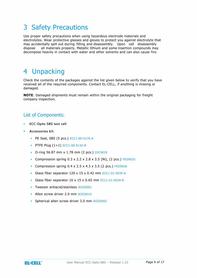
3 Safety Precautions Use proper safety precautions when using hazardous electrode materials and
electrolytes. Wear protective glasses and gloves to protect you against electrolyte that may accidentally spill out during filling and disassembly. Upon cell disassembly
dispose all materials properly. Metallic lithium and some insertion compounds may decompose heavily in contact with water and other solvents and can also cause fire.
4 Unpacking Check the contents of the packages against the list given below to verify that you have
received all of the required components. Contact EL-CELL, if anything is missing or
damaged.
NOTE: Damaged shipments must remain within the original packaging for freight
company inspection.
List of Components:
ECC-Opto-SBS test cell
Accessories kit:
PE Seal, SBS (5 pcs.) ECC1-00-0176-A
PTFE Plug (1+1) ECC1-00-0130-B
O-ring 56.87 mm x 1.78 mm (2 pcs.) DIC9019
Compression spring 0.3 x 2.2 x 2.8 x 3.5 (Ni), (2 pcs.) FED9025
Compression spring 0.4 x 2.5 x 4.3 x 3.5 (2 pcs.) FED9026
Glass fiber separator 120 x 15 x 0.42 mm ECC1-01-0039-A
Glass fiber separator 10 x 15 x 0.65 mm ECC1-01-0039-B
Tweezer antiacid/stainless WZG9001
Allen screw driver 2.0 mm WZG9010
Spherical allen screw driver 3.0 mm WZG9002

Page 7 of 17 User Manual ECC-Opto-SBS – Release 1.23
5 Assembly and connection Generally, all assembly steps are to be carried out in inert glove box atmosphere. All
components used are to be dried upfront in a vacuum oven at 80°C for at least 12 hours. Once fully assembled, the cell is hermetically sealed so that it may be operated
in ambient atmosphere. The ECC-Opto-SBS test cell comes in fully assembled state.
The following procedure explains how to build the test cell for the first experiment.For
subsequent experiments it may be required to disassemble and clean the inner cell.
(Dis-)Assembly:
Before proceeding with the cell assembly, the electrodes, separator and cell parts need
to be dried in a vacuum oven. The inner cell must be thoroughly dried overnight at 120°C as it comprises bulky PEEK parts that absorb moisture; the remaining cell parts
may be dried for at least one hour at only 80°C. The large PE seal between cell lid and base must be dried at maximum 80°C. It may be damaged at higher temperature.
Release the clamp screw at the cell stand and remove the test cell.
Turn the test cell upside down and unscrew the 3 hex socket screws at the cell bottom.
Remove the cell base with the lid. You are now looking onto the inner cell attached to the cell lid by means of 2 clamping claws.
Release the clamping claws (turn 90° counter clockwise) and remove the inner
cell.

Page 8 of 17 User Manual ECC-Opto-SBS – Release 1.23
Note the 2 nickel plated feed wires at the bottom One feed wire contacts the working electrode (WE) and contacts the counter electrode (CE). The graphic on
the lid specifies the position of the inner cell and thus for the working electrode
and the counter electrode too.
Turn it upside down. Now you can see the two ram holders with the square rams,
where the electrodes will be placed. Note the two nickel plated feed pins that will finally make the contact to these electrodes.
If the hight of the electrodes varies, you have different means to adjust the electrodes. There are 4 adjustment screws at the inner cell .
1. The two thrust screws inside the inner cell serves to adjust the electrodes in height. Turning the screw clockwise the electrode moves up. The effect
can be seen more clearly, when you are pressing gently with the finger on the ram holder while turning the screw. Do not overtighten the thrust
screws once the inner cell has been mounted to the cell lid. Doing so may destroy the optical window.

Page 9 of 17 User Manual ECC-Opto-SBS – Release 1.23
2. The two bigger adjustment screws serve to adjust the distance and parallelism between the two electrodes aka the width of the electrolyte
(separator) gap.
Inside the glove box, place the inner cell in front of you with the two adjustment
screws pointing to the right.
Adjust the two opposite thrust screws so as to move the rams into the lowermost position.
Move the right ram and ram holder into the outmost right position by alternately turning the two adjustment screws on the right. Apply only gentle torque; switch
between the two screws when torque builds up.
Place a rectangular piece of the glass fiber separator into the gap between the
squared rams. The upper edge of the separator must have the same height like
the ram holder, because the separator has to touch the glass window.

Page 10 of 17 User Manual ECC-Opto-SBS – Release 1.23
Place the two squared electrodes (9.5 x 9.5 mm) onto the rams on either side of the separator.
Turn the adjustment screws to adjust the gap width and parallelism between the electrodes.
Dispense a small amount of electrolyte (<= 0.2 mL) on the edge of the separator and the surface of the electrode. The amount of electrolyte should be just
sufficient to soak the porous bodies of the separator and the used electrodes, not more and not less.
Attach the inner cell to the cell lid. Watch out to the right position of the inner cell. Tighten the two clamping claws firmly by hand.
Turn the two thrust screws at the inner cell clockwise until the electrodes are
gently pressed against the optical window.
Place the cell case beside the cell lid with the inner cell attached.

Page 11 of 17 User Manual ECC-Opto-SBS – Release 1.23
Insert the large PE seal into the cell base.
Place the cell lid with the inner cell attached onto the cell base.
By hand, screw in the 3 hex socket screws from below.
By means of a hex-wrench, fasten the 3 hex socket screws bit by bit to avoid
excessive stress that may break the optical window
Attach the test cell to the test stand and lock it to the stand by fixing the clamp screw.
Attach one feed wire to port WE and one feed wire to port CE. Close port AUX with the PTFE-plug.

Page 12 of 17 User Manual ECC-Opto-SBS – Release 1.23
6 Spare parts
SBS sapphire window kit, assy
ECC1-00-0161-A
Inner cell SBS, assy
ECC1-00-0215-A PE-Seal, SBS
ECC1-00-0176-A
Cell case, SBS
ECC1-00-0166-A PTFE Plug, assy
ECC1-00-0130-B Feed Wire SBS, assy
ECC1-00-0162-A
Socket screw
DIN 912 M4x25
Feed wire SBS, assy
ECC1-00-0162-A
Socket screw
DIN 912 M4x25
Stand II, ECC-Opto-SBS, assy
ECC1-00-0220-A

Page 13 of 17 User Manual ECC-Opto-SBS – Release 1.23
Top Flange SBS (1mm)
ECC1-00-0163-A
Sapphire window SBS
ECC1-00-0165-A O-Ring 56.87x1.78
DIC9019
Base flange SBS
ECC1-00-0164-A Socket screw
DIN 912 M2x5
SBS Sapphire window kit SBS, assy
Page 14 of 17 User Manual ECC-Opto-SBS – Release 1.23
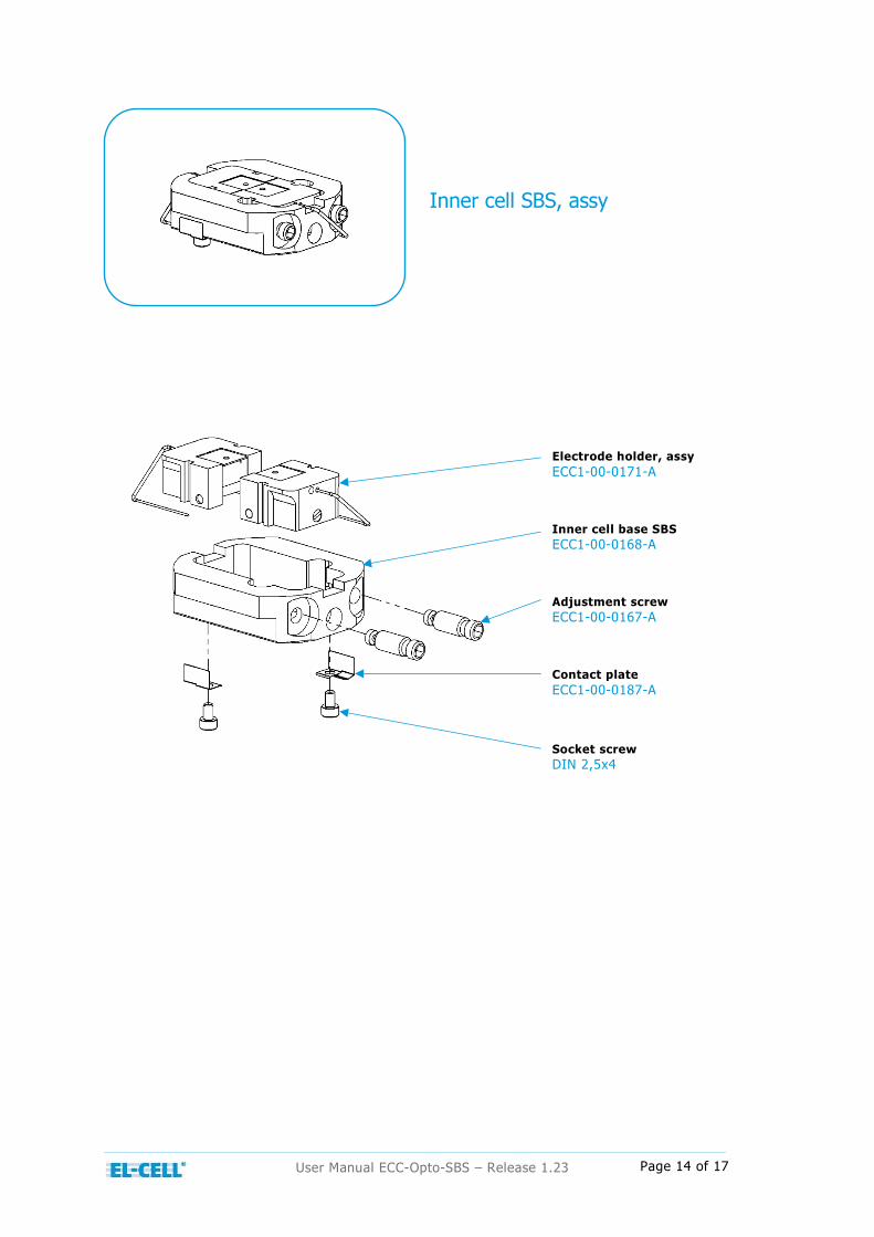
Electrode holder, assy
ECC1-00-0171-A Inner cell base SBS
ECC1-00-0168-A Adjustment screw
ECC1-00-0167-A
Contact plate
ECC1-00-0187-A Socket screw
DIN 2,5x4
Inner cell SBS, assy

Page 15 of 17 User Manual ECC-Opto-SBS – Release 1.23
Ram
ECC1-00-0172-A Electrode feed wire (Au)
ECC1-00-0174-A Thrust screw, SBS
ECC1-00-0175-A
Compression spring 0.4x2.5x4.3x3.5
FED9026 Electrode holder
ECC1-00-0169-A
Electrode holder, assy
Feed pin
ECC1-00-0147-A Compression spring 0.3x2.2x2.8x3.5
FED9025
Lever (SBS)
ECC1-00-0144-A Axle, SBS
ECC1-00-0173-A

Page 16 of 17 User Manual ECC-Opto-SBS – Release 1.23
12 Technical Support Technical support for this product is exclusively provided by EL-CELL GmbH.
EL-CELL GmbH
Tempowerkring 8
21079 Hamburg - Germany
phone: +49 40 79012-737
fax: +49 40 79012-736
e-mail: [email protected]
web: www.el-cell.com

Page 17 of 17 User Manual ECC-Opto-SBS – Release 1.23
13 Warranty For a period of one year from the date of shipment, EL-CELL GmbH (hereinafter Seller)
warrants the goods to be free from defect in material and workmanship to the original purchaser. During the warranty period, Seller agrees to repair or replace defective
and/or nonconforming goods or parts without charge for material or labor, or, at the Seller’s option, demand return of the goods and tender repayment of the price. Buyer’s
exclusive remedy is repair or replacement of defective and nonconforming goods, or, at
Seller’s option, the repayment of the price.
Seller excludes and disclaims any liability for lost profits, personal injury, interruption of
service, or for consequential incidental or special damages arising out of, resulting from, or relating in any manner to these goods.
This Limited Warranty does not cover defects, damage, or nonconformity resulting from abuse, misuse, neglect, lack of reasonable care, modification, or the attachment of
improper devices to the goods. This Limited Warranty does not cover expendable items.
This warranty is void when repairs are performed by a non-authorized person or service center. At Seller’s option, repairs or replacements will be made on site or at the factory.
If repairs or replacements are to be made at the factory, Buyer shall return the goods prepaid and bear all the risks of loss until delivered to the factory. If Seller returns the
goods, they will be delivered prepaid and Seller will bear all risks of loss until delivery
to Buyer. Buyer and Seller agree that this Limited Warranty shall be governed by and construed in accordance with the laws of Germany.
The warranties contained in this agreement are in lieu of all other warranties expressed or implied, including the warranties of merchantability and fitness for a particular
purpose.
This Limited Warranty supersedes all prior proposals or representations oral or written
and constitutes the entire understanding regarding the warranties made by Seller to
Buyer. This Limited Warranty may not be expanded or modified except in writing signed by the parties hereto.