Embed Size (px)
Citation preview
Page 1
User Manual
LVRSys™
Low Voltage Regulator SystemTM
(Low voltage regulator system)
Page 2 Contents
We take care of it.
Contents
Contents 2
1. Overview ....................................................................................................................... 5
1.1 Target group ............................................................................................................................. 5
1.2 Warnings ................................................................................................................................... 5
1.3 Tips ............................................................................................................................................ 5
1.4 Other symbols ........................................................................................................................... 6
1.5 Applicable documentation ........................................................................................................ 6
1.6 Storage ...................................................................................................................................... 6
2. Scope of Delivery/Options .............................................................................................. 7
2.1 Scope of delivery standard system ........................................................................................... 7
2.2 Options ...................................................................................................................................... 7
2.2.1 Modifications bus system/BYPASS ........................................................................................... 7
2.2.2 Voltage/current measurements ............................................................................................... 7
2.2.3 Power output ............................................................................................................................ 7
2.2.4 External components ................................................................................................................ 7
2.2.5 Power quality measurement .................................................................................................... 7
2.2.6 Pivot lever locking cylinder ....................................................................................................... 7
3. Safety instructions .......................................................................................................... 8
4. Technical Data ................................................................................................................ 9
5. Intended use ................................................................................................................ 11
6. Description and Principle of Operation .......................................................................... 12
7. Installation ................................................................................................................... 15
7.1 System overview ..................................................................................................................... 15
7.2 Packaging and Transport ........................................................................................................ 19
7.2.1 Packaging ................................................................................................................................ 19
7.2.2 Transport on pallets ................................................................................................................ 20
7.2.3 Transport by crane .................................................................................................................. 21
7.3 Cover ....................................................................................................................................... 23
7.4 LVRSys™ assembly .................................................................................................................. 24
7.4.1 Base hole for grounding base ................................................................................................. 24
7.4.2 Mounting the grounding base ................................................................................................ 25
7.4.3 Installing the LVRSys™ on a concrete base ............................................................................. 27
7.4.4 Local grounding point ............................................................................................................. 27
7.5 Connecting the low-voltage cable .......................................................................................... 28
Page 3
8. Putting the LVRSys™ into operation and taking it out of operation ................................. 29
8.1 Putting the LVRSys™ into operation ...................................................................................... 30
8.2 Taking LVRSys™ out of operation and BYPASS mode ............................................................ 31
9. Operation/Regulator operation ..................................................................................... 32
9.1 Operating Conditions Temperature ....................................................................................... 32
9.2 Indicator lamps and switches................................................................................................. 33
9.2.1 Indicator lamps ...................................................................................................................... 33
9.2.2 Switch ..................................................................................................................................... 34
9.3 Boot process .......................................................................................................................... 34
9.4 Menu navigation .................................................................................................................... 35
9.5 Automatic mode .................................................................................................................... 36
9.6 Blocked mode ........................................................................................................................ 36
9.7 Manual mode ......................................................................................................................... 37
9.8 Overview of the displays ........................................................................................................ 38
9.9 Parameters ............................................................................................................................. 38
9.9.1 Set point ................................................................................................................................. 40
9.9.2 Tolerance band+ and tolerance band- ................................................................................... 40
9.9.3 Time delay .............................................................................................................................. 41
9.9.4 Grid impedance ...................................................................................................................... 42
9.9.5 Synchro phasing ..................................................................................................................... 43
9.10 Setup ...................................................................................................................................... 43
9.10.1 Phase spacing ......................................................................................................................... 43
9.10.2 KNI (current transformer factor)............................................................................................ 44
9.10.3 Communication ...................................................................................................................... 44
9.10.4 Language ................................................................................................................................ 45
9.10.5 Delete statistics ...................................................................................................................... 45
9.11 Flyback hand .......................................................................................................................... 45
9.12 Info/Update ............................................................................................................................ 46
9.12.1 Firmware update .................................................................................................................... 46
9.12.2 LOG ERR ................................................................................................................................. 47
9.12.3 Archive log book..................................................................................................................... 47
9.12.4 Evaluate logbook (Measurement data) with Microsoft Excel ............................................... 49
9.12.5 Evaluate logbook (Event data) in Notepad++ ........................................................................ 53
9.13 Communication ...................................................................................................................... 54
9.13.1 Modbus .................................................................................................................................. 54
9.13.2 Additional log files.................................................................................................................. 56

Page 4 Contents
We take care of it.
10. Controls and Power stage ............................................................................................. 57
10.1 Controls ................................................................................................................................... 57
10.2 Interfaces and log files ............................................................................................................ 58
10.2.1 USB .......................................................................................................................................... 58
10.2.2 Ethernet .................................................................................................................................. 58
10.2.3 RS 232 ..................................................................................................................................... 58
10.2.4 RS 485 ..................................................................................................................................... 59
10.3 Power stage ............................................................................................................................ 59
10.4 Current transformers .............................................................................................................. 59
11. External devices and modifications ............................................................................... 61
11.1 External devices ...................................................................................................................... 61
11.2 Modification voltage & current measurement ....................................................................... 62
11.3 Modification ............................................................................................................................ 62
11.4 PQI-DA smart .......................................................................................................................... 63
12. Servicing/Cleaning/Spare parts ..................................................................................... 64
12.1 Switch cabinet ......................................................................................................................... 64
12.2 Power stage ............................................................................................................................ 66
12.3 Bus system .............................................................................................................................. 68
12.4 Spare/Replacement parts ....................................................................................................... 69
12.5 Controls ................................................................................................................................... 70
13. Standards and Laws ...................................................................................................... 71
14. Disassembly and disposal ............................................................................................. 72
15. Guarantee .................................................................................................................... 72
Page 5
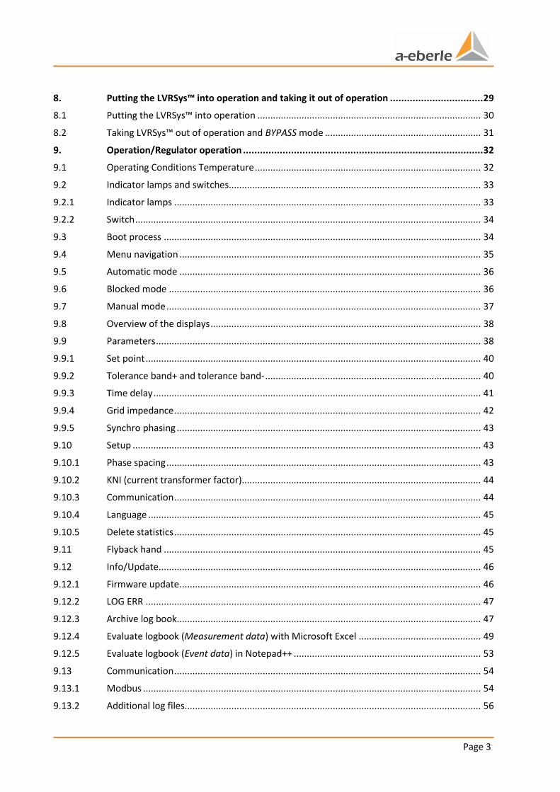
1. Overview
This User Manual is a summary of the information needed for the installation, putting into operation and operation of the low-voltage regulator.
Read the User Manual in its entirety and do not use the product unless you have understood what you read.
1.1 Target group
The User Manual is intended for skilled technicians as well trained and certified operators.
The contents of this User Manual must be accessible to people tasked with the installation and operation of the system.
1.2 Warnings
Structure of the warnings
Warnings are structured as follows:
SIGNAL WORD
Nature and source of the danger.
Consequences in the event of non-observance.
Actions to avoid the danger.
Types of warnings
Warnings are distinguished by the type of danger they are warning against:
DANGER! Warns of an immediately impending danger that can result in death or serious injuries when not avoided.
WARNING! Warns of a potentially dangerous situation that can result in death or serious injuries when not avoided.
CAUTION! Warns of a potentially dangerous situation that can result in fairly serious or light injuries when not avoided.
NOTICE: Warns of a potentially dangerous situation that results in material or environmental damage when not avoided.
1.3 Tips
Tips on the appropriate device use and recommendations.
Page 6 Overview
We take care of it.
1.4 Other symbols
Instructions
Structure of the instructions:
Instructions for an action.
Indication of an outcome, if necessary.
Lists
Structure of unnumbered lists:
0 List level 1
– List level 2
Structure of numbered lists:
1) List level 1
2) List level 1
1. List level 2
2. List level 2
1.5 Applicable documentation
For the safe and correct use of the product, observe the additional documentation that is delivered with the system as well as the relevant standards and laws.
1.6 Storage
Store the user manual, including the supplied documentation, readily accessible near the system.
Page 7
2. Scope of Delivery/Options
2.1 Scope of delivery standard system
0 Concrete base (for outdoor installation)
0 Steel base (for indoor installation)
0 LVRSys™ switch cabinet
0 LVRSys™ user manual
0 Circuit diagram LVRSys™ switch cabinet
2.2 Options
2.2.1 Modifications bus system/BYPASS
0 Additional inflows (integration of a cable distribution cabinet)
0 Additional outflows (integration of a cable distribution cabinet)
0 NH separator in a different version.
Larger modifications to the bus system increase the size of the switch cabinet.
2.2.2 Voltage/current measurements
In the standard system, the regulator only needs the output voltages of the LVRSys™. The output has 2 x 3 test connections. Measurements can be extended by:
0 Voltage taps at the input of the LVRSys™
0 Current measurement/converter at the input of the LVRSys™
0 Current measurement/converter at the output of the LVRSys™
2.2.3 Power output
0 Schuko socket with FI fuse.
2.2.4 External components
0 Measuring devices, remote controls, etc… can be installed in the cabinet upfront if so agreed in the planning phase.
2.2.5 Power quality measurement
0 Power quality measurement at LVRSys™ input
0 Power quality measurement at LVRSys™ output
2.2.6 Pivot lever locking cylinder
0 Modifications can be made to the locking system on request.
Page 8 Safety instructions
We take care of it.
3. Safety instructions
Follow the operating instructions.
Keep the operating instructions with the device.
Do not operate the device if it is not in impeccable condition.
Make sure the device is only operated by qualified personnel.
Connect the device as specified.
Make sure the device is not operated outside the design limits (see Sec. 4 Technical Da-
ta).
Do not use the device in environments where explosive gases, dust or fumes occur
Make sure the front covers are present and close properly.
Clean the device only with commercially available cleaning agents.

Page 9
4. Technical Data
Ambient temperature -40°C to 45°C
Maximum permitted air temperature in the switch cabinet
70 °C
Altitude of the installation (NN) < 2000 m
Safety class IP 54
Rated voltage 400 V/230 V ±20% (L-L/LE)
Rated current
80 A (55 kVA system)
160 A (110 kVA system)
250 A (175 kVA system)
315 A (250 kVA system)
580 A (400 kVA system)
Rated frequency 50 Hz
Efficiency 99.5% - 99.7%
Standard regulation range
Extended regulation range
±6% of
±10% of
Step number/Distance 6%
Step number/Distance 10%
9/1.5%
9/2.5%
Switch cabinet dimensions W/D/H
120 cm/40 cm/135 cm (55 kVA system ±6%)
120 cm/40 cm/135 cm (55 kVA system ±10%)
120 cm/40 cm/135 cm (110 kVA system ±6%)
140 cm/40 cm/145 cm (110 kVA system ±10%)
140 cm/40 cm/145 cm (175 kVA system ±6%)
140 cm/40 cm/145 cm (175 kVA system ±10%)
160 cm/40 cm/155 cm (250 kVA system ±6%)
160 cm/40 cm/155 cm (250 kVA system ±10%)
160 cm/40 cm/155 cm (400 kVA system ±6%)
Weight switch cabinet
200 kg (55 kVA system ±6%)
240 kg (55 kVA system ±10%)
230 kg (110 kVA system ±6%)
280 kg (110 kVA system ±10%)
320 kg (175 kVA system ±6%)
400 kg (175 kVA system ±10%)
430 kg (250 kVA system ±6%)
550 kg (250 kVA system ±10%)
540 kg (400 kVA system ±6%)

Page 10 Technical Data
We take care of it.
Dimensions grounding base W/D/H
120 cm/40 cm/100 cm (55 kVA system ±6%)
120 cm/40 cm/100 cm (55 kVA system ±10%)
120 cm/40 cm/100 cm (110 kVA system ±6%)
140 cm/50 cm/100 cm (110 kVA system ±10%)
140 cm/50 cm/100 cm (175 kVA system ±6%)
140 cm/50 cm/100 cm (175 kVA system ±10%)
160 cm/50 cm/100 cm (250 kVA system ±6%)
160 cm/50 cm/100 cm (250 kVA system ±10%)
160 cm/50 cm/100 cm (400 kVA system ±6%)
Weight grounding base
260 kg (55 kVA system ±6%)
260 kg (55 kVA system ±10%)
260 kg (110 kVA system ±6%)
280 kg (110 kVA system ±10%)
280 kg (175 kVA system ±6%)
280 kg (175 kVA system ±10%)
300 kg (250 kVA system ±6%)
300 kg (250 kVA system ±10%)
300 kg (400 kVA system ±6%)
Power consumption control units 100 mA (230 V)
Cooling - passive (convection via switch cabinet housing)
- active (redundant ventilation system)
(depending on the application conditions)
Short-circuit impedance
0.22% (55 kVA system ±6%)
0.26% (55 kVA system ±10%)
0.15% (110 kVA system ±6%)
0.28% (110 kVA system ±10%)
0.14% (175 kVA system ±6%)
0.24% (175 kVA system ±10%)
0.14% (250 kVA system ±6%)
0.21% (250 kVA system ±10%)
0.13% (400 kVA system ±6%)
Maximum phasing duration 30 ms
Noise emissions < 30 dB(A)
Electromagnetic immunity DIN EN 61000-6-1
Electromagnetic interference DIN EN 61000-6-3
Assembly instructions DIN EN 61439-1/5
Low voltage directive 2014/35/EU
Table 4-1 Technical data
Page 11
Intended use
5. Intended use
This product is designed exclusively to regulate voltage at the low voltage level (400V L-L).
Description and Principle of Operation Page 12
We take care of it.
6. Description and Principle of Operation
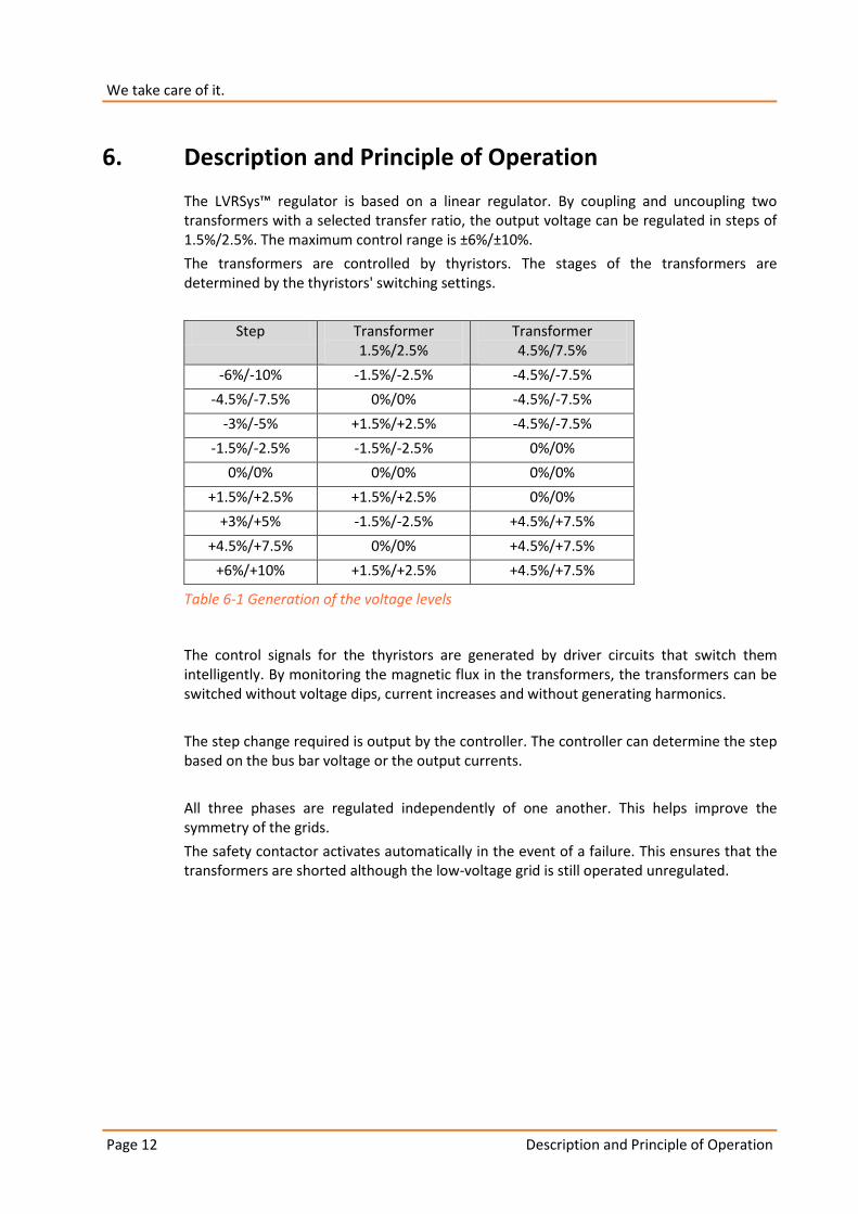
The LVRSys™ regulator is based on a linear regulator. By coupling and uncoupling two transformers with a selected transfer ratio, the output voltage can be regulated in steps of 1.5%/2.5%. The maximum control range is ±6%/±10%.
The transformers are controlled by thyristors. The stages of the transformers are determined by the thyristors' switching settings.
Step Transformer 1.5%/2.5%
Transformer 4.5%/7.5%
-6%/-10% -1.5%/-2.5% -4.5%/-7.5%
-4.5%/-7.5% 0%/0% -4.5%/-7.5%
-3%/-5% +1.5%/+2.5% -4.5%/-7.5%
-1.5%/-2.5% -1.5%/-2.5% 0%/0%
0%/0% 0%/0% 0%/0%
+1.5%/+2.5% +1.5%/+2.5% 0%/0%
+3%/+5% -1.5%/-2.5% +4.5%/+7.5%
+4.5%/+7.5% 0%/0% +4.5%/+7.5%
+6%/+10% +1.5%/+2.5% +4.5%/+7.5%
Table 6-1 Generation of the voltage levels
The control signals for the thyristors are generated by driver circuits that switch them intelligently. By monitoring the magnetic flux in the transformers, the transformers can be switched without voltage dips, current increases and without generating harmonics.
The step change required is output by the controller. The controller can determine the step based on the bus bar voltage or the output currents.
All three phases are regulated independently of one another. This helps improve the symmetry of the grids.
The safety contactor activates automatically in the event of a failure. This ensures that the transformers are shorted although the low-voltage grid is still operated unregulated.
Page 13
Description and Principle of Operation
V_in
V_o
ut
TC
F
T
S
TR2TR1
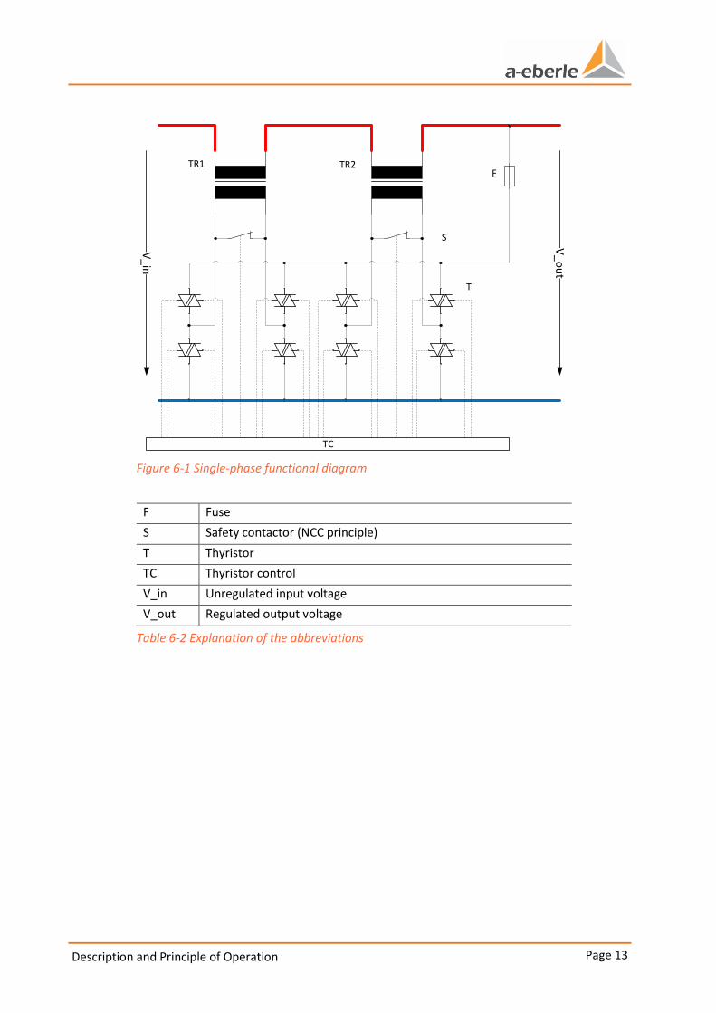
Figure 6-1 Single-phase functional diagram
F Fuse
S Safety contactor (NCC principle)
T Thyristor
TC Thyristor control
V_in Unregulated input voltage
V_out Regulated output voltage
Table 6-2 Explanation of the abbreviations

Description and Principle of Operation Page 14
We take care of it.
V_in
V_o
ut
TC
4,5% TR 1,5% TR
Figure 6-2 Example of 3% voltage reduction
In the example shown in Figure 6-2, the output voltage is reduced by 3% compared with the input volt-
age. The transformer 4.5% TR converts the primary voltage, which is switched by thyristors, in a
negative direction and subtracts 10.35 V (4.5% of 230 V) from the output voltage. The transformer 1.5%
TR converts the primary voltage in a positive direction and adds 3.45 V (1.5% of 230 V) to the output
voltage.

Page 15
Installation
7. Installation
7.1 System overview
PEN
LVRSys™
21
3
4
Figure 7-3 LVRSys Connection overview of low-voltage cables 55 kVA (6%/10%)/110 kVA (6%)
1 Terminal block for cable input
(for copper and aluminium conductors; Cross section 95 mm² - 185 mm²; Allen 4 mm; torque 12 - 15 Nm)
2 Terminal block for cable output
(for copper and aluminium conductors; Cross section 95 mm² - 185 mm²; Allen 4 mm; torque 12 - 15 Nm)
3 PEN bus (3 x rivet nut M12)
4 Concrete base
Installation Page 16
We take care of it.
PEN
LVRSys™
21
3
4
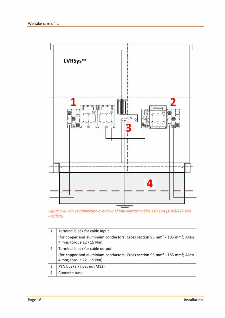
Figure 7-4 LVRSys connection overview of low-voltage cables 110 kVA (10%)/175 kVA 6%/10%)
1 Terminal block for cable input
(for copper and aluminium conductors; Cross section 95 mm² - 185 mm²; Allen 4 mm; torque 12 - 15 Nm)
2 Terminal block for cable output
(for copper and aluminium conductors; Cross section 95 mm² - 185 mm²; Allen 4 mm; torque 12 - 15 Nm)
3 PEN bus (3 x rivet nut M12)
4 Concrete base
Page 17
Installation
PEN
LVRSys™
21
3
4
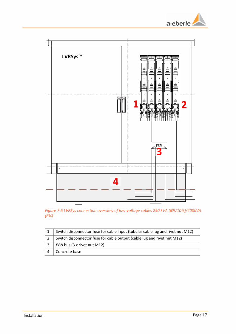
Figure 7-5 LVRSys connection overview of low-voltage cables 250 kVA (6%/10%)/400kVA (6%)
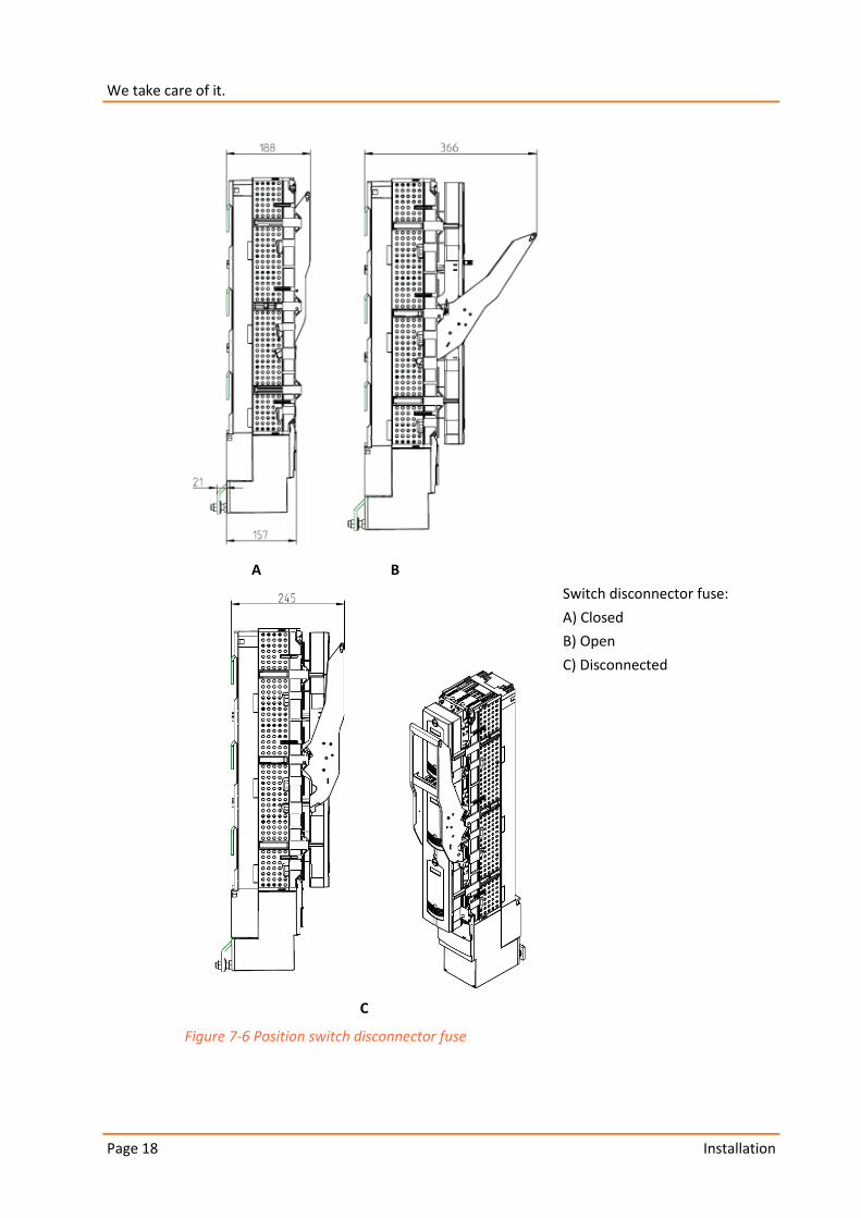
1 Switch disconnector fuse for cable input (tubular cable lug and rivet nut M12)
2 Switch disconnector fuse for cable output (cable lug and rivet nut M12)
3 PEN bus (3 x rivet nut M12)
4 Concrete base
Installation Page 18
We take care of it.
A B
Switch disconnector fuse:
A) Closed
B) Open
C) Disconnected
C
Figure 7-6 Position switch disconnector fuse

Page 19
Installation
7.2 Packaging and Transport
7.2.1 Packaging
Figure 7-1 Packaging and shock stickers
To protect the system, the packaging consists of USB plates.
Check the shock stickers before opening.
For red stickers:
Do not remove the packaging.
Contact A. Eberle GmbH & Co. KG.

Installation Page 20
We take care of it.
7.2.2 Transport on pallets
CAUTION! Switch cabinet can be damaged if handled incorrectly during transport!
Only transport LVRSys™ in an upright position.
Make sure the switch cabinet cannot topple over.
Fastening mounting devices on the board wall.
Figure 7-2 Transporting the cabinet by lorry
Page 21
Installation
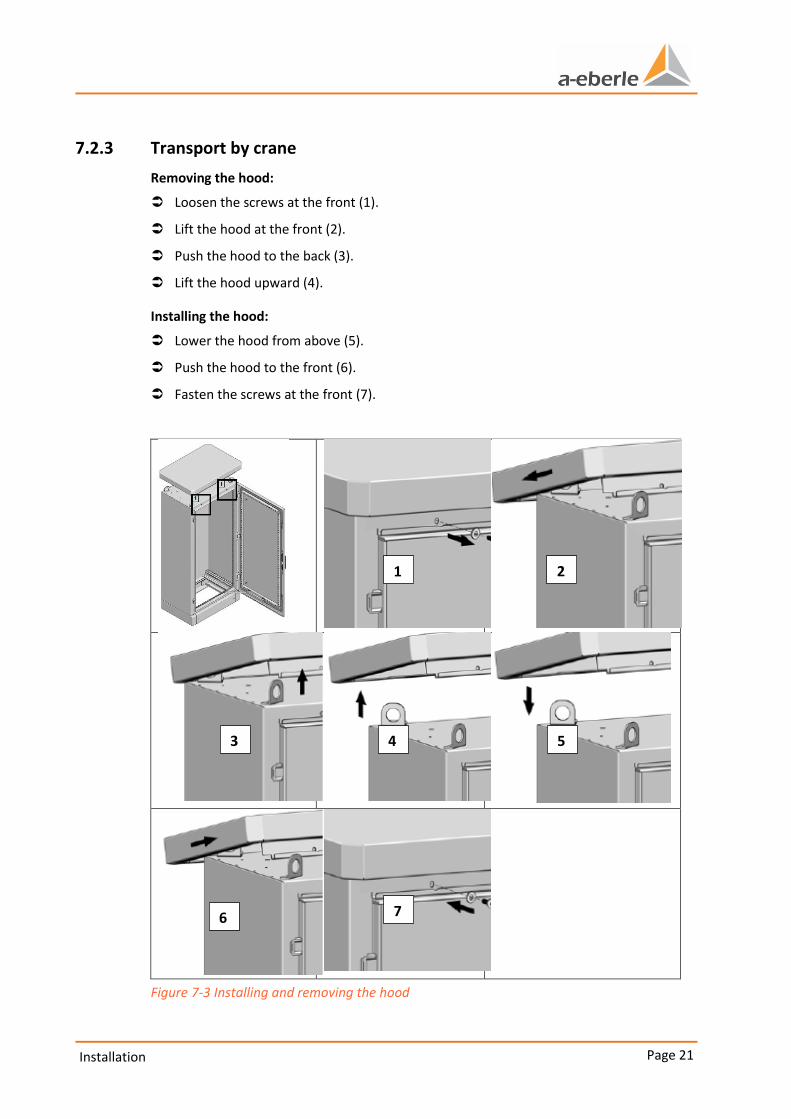
7.2.3 Transport by crane
Removing the hood:
Loosen the screws at the front (1).
Lift the hood at the front (2).
Push the hood to the back (3).
Lift the hood upward (4).
Installing the hood:
Lower the hood from above (5).
Push the hood to the front (6).
Fasten the screws at the front (7).
Figure 7-3 Installing and removing the hood
1 2
3 4 5
6 7
Installation Page 22
We take care of it.
The screws can be loosened and fastened with a TX 25 screwdriver. The tightening torque may not exceed 6 Nm.
DANGER! Falling switch cabinet is a danger to life!
Make sure no one is below a hanging load.
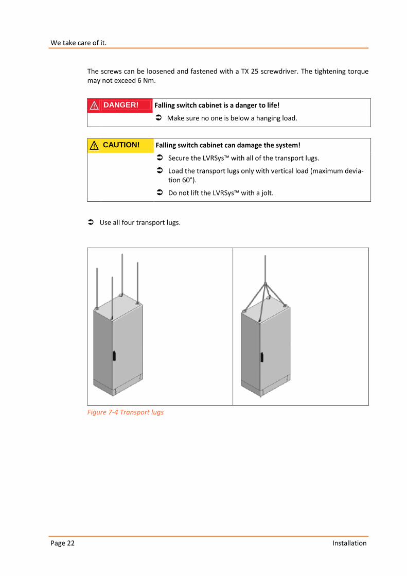
CAUTION! Falling switch cabinet can damage the system!
Secure the LVRSys™ with all of the transport lugs.
Load the transport lugs only with vertical load (maximum devia-tion 60°).
Do not lift the LVRSys™ with a jolt.
Use all four transport lugs.
Figure 7-4 Transport lugs

Page 23
Installation
7.3 Cover
Installing and removing the locking cylinder:
Turn the cover cap to the right to open it (1).
Insert the key in the locking cylinder and turn right to open (2).
Unscrew fastening screw (M5) from the locking cylinder (3).
Pull out the locking cylinder towards the switch cabinet (4).
Slide in the new locking cylinder (5).
Screw fastening screw (M5) into the locking cylinder (6).
Insert the key in the locking cylinder and turn left to lock (7).
Turn cover cap left to close (8).
Figure 7-5 Installing and removing the locking cylinder
1 2
3 4 5
6 7 8

Installation Page 24
We take care of it.
The screws can be loosened and fastened with a Philips (crosshead) screwdriver. The tightening torque is between 1.5 Nm and 2.5 Nm.
7.4 LVRSys™ assembly
Make sure there is sufficient ventilation to extract the heat.
Observe the following minimum distances:
– 10 cm to walls or other switch cabinets
– 50 cm to the ceiling
– 100 cm to 120 cm near doors.
Avoid direct sunlight.
7.4.1 Base hole for grounding base
Cut out a base hole that is 95 to 100 cm deep.
Found it with 30 cm of broken stones and gravel.
Install the grounding base (see Sec. 7.4.2 Mounting the grounding base).
Install the grounding base.
Figure 7-6 Founding
Page 25
Installation
7.4.2 Mounting the grounding base
Two people are needed to set up the base.
Required tools
0 Spirit level
0 Wrench 13 and 19, 25 Nm.
When edging the base with flagging or similar material, a minimum distance to the base of 5 cm must be observed as an expansion gap.
Do not bring vibratory equipment in contact with the base.
To avoid the collection of condensation around the base, seal the final layer of filling in the base with suitable material.
Recommendation:
0 Dry fine gravel as the bottom layer
0 Dry river sand as the middle layer
0 Poor concrete, gas concrete or styrofoam as the final layer.
The grounding base is made of light-weight concrete and consists of:
0 Foundation plate
0 Two side components
0 Two split base plates
0 Installation material
0 Fastening screws.
To give the sides more stability, support them with earth-moist concrete.
Installation Page 26
We take care of it.
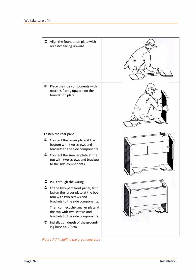
Align the foundation plate with recesses facing upward
Place the side components with notches facing upward on the foundation plate.
Fasten the rear panel:
Connect the larger plate at the bottom with two screws and brackets to the side components.
Connect the smaller plate at the top with two screws and brackets to the side components.
Pull through the wiring.
Of the two-part front panel, first fasten the larger plate at the bot-tom with two screws and brackets to the side components.
Then connect the smaller plate at the top with two screws and brackets to the side components.
Installation depth of the ground-ing base ca. 70 cm
Figure 7-7 Installing the grounding base
Page 27
Installation
7.4.3 Installing the LVRSys™ on a concrete base
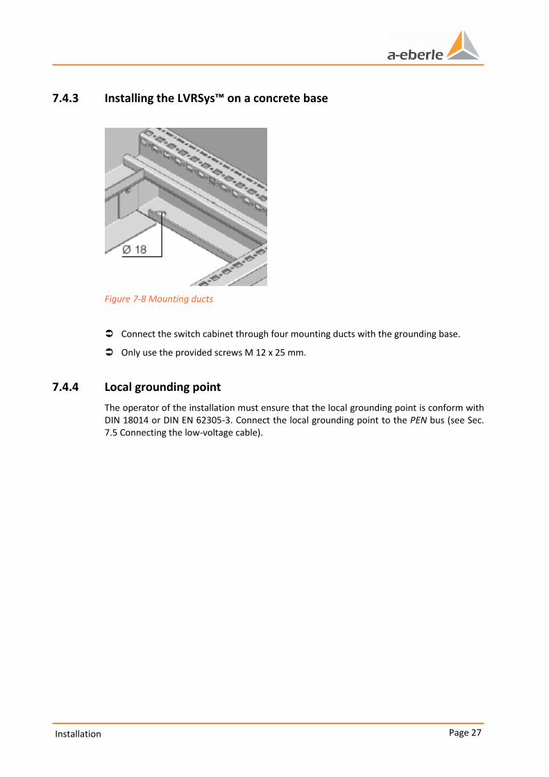
Figure 7-8 Mounting ducts
Connect the switch cabinet through four mounting ducts with the grounding base.
Only use the provided screws M 12 x 25 mm.
7.4.4 Local grounding point
The operator of the installation must ensure that the local grounding point is conform with DIN 18014 or DIN EN 62305-3. Connect the local grounding point to the PEN bus (see Sec. 7.5 Connecting the low-voltage cable).
Installation Page 28
We take care of it.
7.5 Connecting the low-voltage cable
DANGER! Danger of electric shock!
Make sure the LVRSys™ is de-energized before connecting it.
CAUTION! Destruction of components due to overload!
Use cable clasps in the LVRSys™ system's inputs and outputs.
CAUTION! Destruction of components due to overload!
Only switch on the low voltage grid in BYPASS mode. (See Sec. 8.2 Taking LVRSys™ out of operation and BYPASS mode).
Sequence:
Isolate the low voltage grid.
Clamp L1/L2/L3 according to DIN EN 61439 (See Sec. 7.1 System overview).
Clamp PEN/local cabinet grounding according to DIN EN 61439 (See Sec. 7.1 System
overview).
Install the cable clips on C profile rails under input and output.
Couple the low voltage grid.
Page 29
Putting the LVRSys™ into operation and taking it out of operation
8. Putting the LVRSys™ into operation and taking it out
of operation
DANGER! Danger of electric shock!
Never open the NH separator partially.
Always use the handle to open the lid.
NH fuses are intended exclusively for use by skilled electricians or people trained in electrotechnical work, see IEC 60269-2.
The following must be observed when switching devices:
Make sure the device is put into and taken out of operation and operated by skilled electricians only or people who have been trained according to VDE 0105-100.
Use the handle to operate the fuse lid.
Before switching on, make sure the fuse lid is stored or led in the open position.
If the lid is partially open, fuse units can be under current.
Putting the LVRSys™ into operation and taking it out of operation Page 30
We take care of it.
8.1 Putting the LVRSys™ into operation
The initial position is:
0 Closed BYPASS.
0 Open input (LVRSys IN).
0 Open output (LVRSys OUT).
0 The regulator in position Off.
CAUTION! Destruction of components due to overload!
Only switch on the LVRSys™ according to the described process.
Close LVRSys IN.
Close LVRSys OUT.
Open LVRSys BYPASS.
Switch regulator to ON position (See Sec. 9.2.2 Switch).
Regulator automatically moves up.
LVRSys™ is active.
Local network is regulated over LVRSys™.
Page 31
Putting the LVRSys™ into operation and taking it out of operation
8.2 Taking LVRSys™ out of operation and BYPASS mode
The initial position is:
0 Closed input (LVRSys IN).
0 Closed output (LVRSys OUT).
0 The regulator in position ON.
0 Open BYPASS.
CAUTION! Destruction of components due to overload!
Isolate the LVRSys™ only according to the described process.
Switch regulator to OFF position (see Sec. 9.2.2 Switch).
Secondary electronics (regulator/actuator/contactors) are de-energized.
Transformers are short-circuited through opener contactors.
Close LVRSys BYPASS.
Open LVRSys OUT.
Open LVRSys IN.
LVRSys™ is isolated from the grid.
BYPASS is active.
The local grid is supplied through the BYPASS.
Operation/Regulator operation Page 32
We take care of it.
9. Operation/Regulator operation
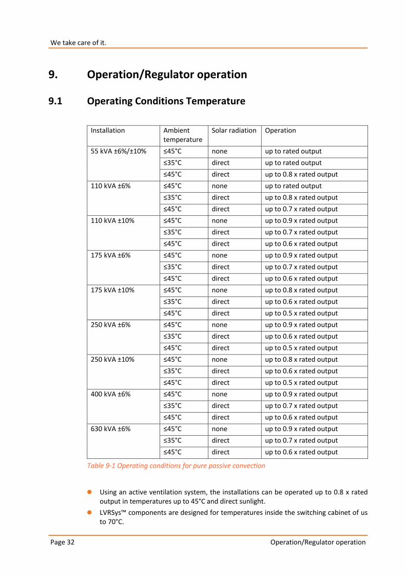
9.1 Operating Conditions Temperature
Installation Ambient temperature
Solar radiation Operation
55 kVA ±6%/±10% ≤45°C none up to rated output
≤35°C direct up to rated output
≤45°C direct up to 0.8 x rated output
110 kVA ±6% ≤45°C none up to rated output
≤35°C direct up to 0.8 x rated output
≤45°C direct up to 0.7 x rated output
110 kVA ±10% ≤45°C none up to 0.9 x rated output
≤35°C direct up to 0.7 x rated output
≤45°C direct up to 0.6 x rated output
175 kVA ±6% ≤45°C none up to 0.9 x rated output
≤35°C direct up to 0.7 x rated output
≤45°C direct up to 0.6 x rated output
175 kVA ±10% ≤45°C none up to 0.8 x rated output
≤35°C direct up to 0.6 x rated output
≤45°C direct up to 0.5 x rated output
250 kVA ±6% ≤45°C none up to 0.9 x rated output
≤35°C direct up to 0.6 x rated output
≤45°C direct up to 0.5 x rated output
250 kVA ±10% ≤45°C none up to 0.8 x rated output
≤35°C direct up to 0.6 x rated output
≤45°C direct up to 0.5 x rated output
400 kVA ±6% ≤45°C none up to 0.9 x rated output
≤35°C direct up to 0.7 x rated output
≤45°C direct up to 0.6 x rated output
630 kVA ±6% ≤45°C none up to 0.9 x rated output
≤35°C direct up to 0.7 x rated output
≤45°C direct up to 0.6 x rated output
Table 9-1 Operating conditions for pure passive convection
0 Using an active ventilation system, the installations can be operated up to 0.8 x rated output in temperatures up to 45°C and direct sunlight.
0 LVRSys™ components are designed for temperatures inside the switching cabinet of us to 70°C.
Page 33
Operation/Regulator operation
0 NH fuse units are limiting elements that cannot be operated at their rated output at temperatures over 40°C.
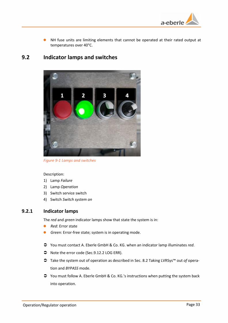
9.2 Indicator lamps and switches
Figure 9-1 Lamps and switches
Description:
1) Lamp Failure
2) Lamp Operation
3) Switch service switch
4) Switch Switch system on
9.2.1 Indicator lamps
The red and green indicator lamps show that state the system is in:
0 Red: Error state
0 Green: Error-free state; system is in operating mode.
You must contact A. Eberle GmbH & Co. KG. when an indicator lamp illuminates red.
Note the error code (Sec.9.12.2 LOG ERR).
Take the system out of operation as described in Sec. 8.2 Taking LVRSys™ out of opera-
tion and BYPASS mode.
You must follow A. Eberle GmbH & Co. KG.'s instructions when putting the system back
into operation.
Operation/Regulator operation Page 34
We take care of it.
9.2.2 Switch
The switch settings create the following states:
0 SwitchSwitch system on:
– Switch to the right: System on
– Switch upward: System off
0 Switch service switch:
– Switch to the right: Switch service active:
– Switch upward: Switch service inactive:
The use of the service switch is reserved for firmware updates.
9.3 Boot process
Activating the System on switch automatically starts the regulator's boot process.
After 25 seconds, the display shows Boot....
After completing the boot process (ca. 45 sec), the regulator is in 'Automatic'
mode.
The boot process must be completed in order to perform all other activities such as configuration, changing the display pages, etc.
Page 35
Operation/Regulator operation
9.4 Menu navigation
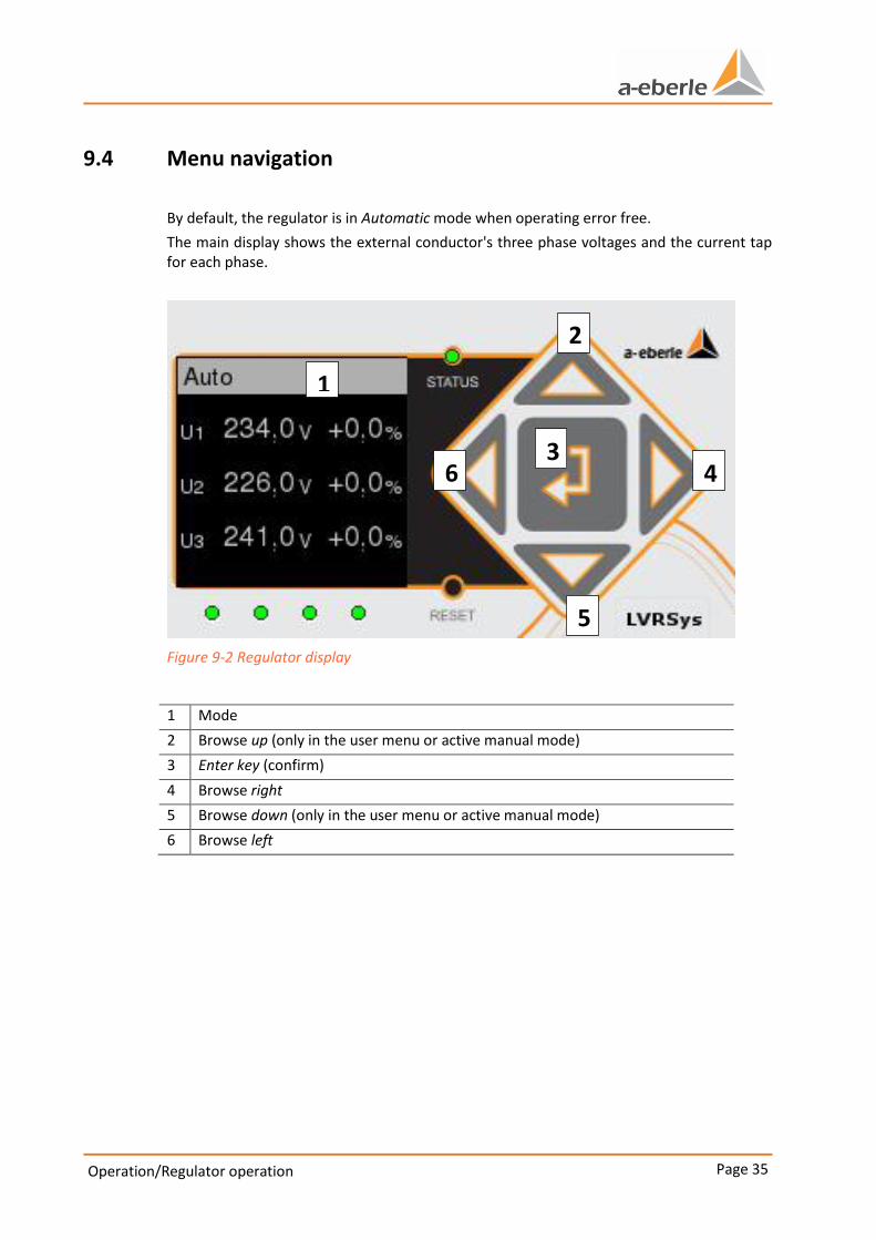
By default, the regulator is in Automatic mode when operating error free.
The main display shows the external conductor's three phase voltages and the current tap for each phase.
Figure 9-2 Regulator display
1 Mode
2 Browse up (only in the user menu or active manual mode)
3 Enter key (confirm)
4 Browse right
5 Browse down (only in the user menu or active manual mode)
6 Browse left
1
2
3 4
5
6

Operation/Regulator operation Page 36
We take care of it.
9.5 Automatic mode
The regulator is active in Automatic mode. After the boot process (connecting the supply voltage) has finished, the regulator switches into Automatic mode.
Figure 9-3 Automatic mode
The display shows:
0 three phase voltages
0 the phases' current tap position
9.6 Blocked mode
The regulator is blocked in blocked mode. Only the Enter key can be activated.
Figure 9-4 Blocked mode display
Page 37
Operation/Regulator operation
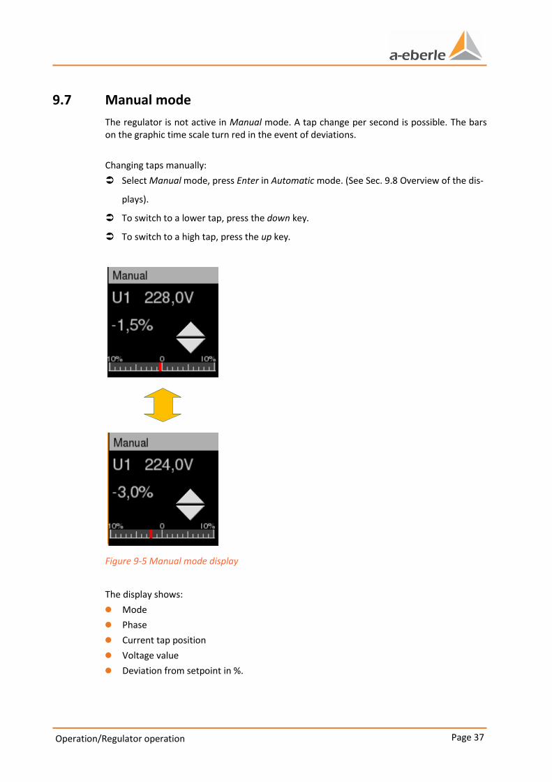
9.7 Manual mode
The regulator is not active in Manual mode. A tap change per second is possible. The bars on the graphic time scale turn red in the event of deviations.
Changing taps manually:
Select Manual mode, press Enter in Automatic mode. (See Sec. 9.8 Overview of the dis-
plays).
To switch to a lower tap, press the down key.
To switch to a high tap, press the up key.
Figure 9-5 Manual mode display
The display shows:
0 Mode
0 Phase
0 Current tap position
0 Voltage value
0 Deviation from setpoint in %.
Operation/Regulator operation Page 38
We take care of it.
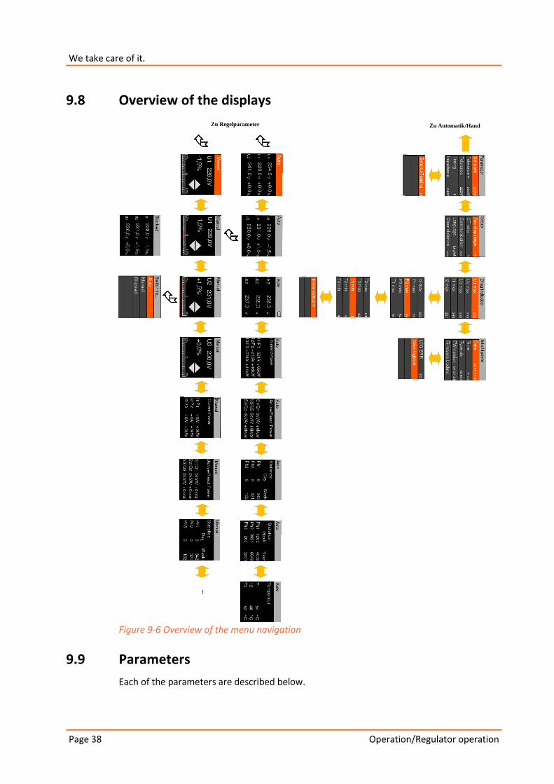
9.8 Overview of the displays
Zu Regelparameter Zu Automatik/Hand
...
Figure 9-6 Overview of the menu navigation
9.9 Parameters
Each of the parameters are described below.
Page 39
Operation/Regulator operation
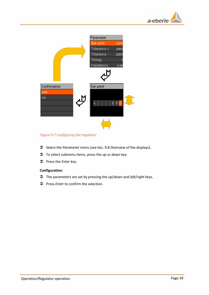
Figure 9-7 Configuring the regulator
Select the Parameter menu (see Sec. 9.8 Overview of the displays).
To select submenu items, press the up or down key.
Press the Enter key.
Configuration:
The parameters are set by pressing the up/down and left/right keys.
Press Enter to confirm the selection.

Operation/Regulator operation Page 40
We take care of it.
9.9.1 Set point
The default is 230 V.
Set the set point.
9.9.2 Tolerance band+ and tolerance band-
The defaults are:
0 225 V for tolerance band– (Tolband neg)
0 235 V for tolerance band+ (Tolband pos)
Set the tolerance bands.
Figure 9-8 Tolerance band zone
1 Regulator active
2 Phasing process
3 Regulator inactive
4 Set point
5 Tolerance bands (tolerance band-/and tolerance band+)
The regulator is inactive if the area between the tolerance bands is under voltage. When the tolerance bands are exceeded, the regulator is activated and as such it will switch the phases according to the parameter settings.
Page 41
Operation/Regulator operation
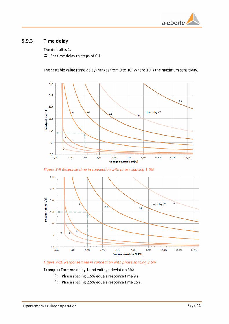
9.9.3 Time delay
The default is 1.
Set time delay to steps of 0.1.
The settable value (time delay) ranges from 0 to 10. Where 10 is the maximum sensitivity.
Figure 9-9 Response time in connection with phase spacing 1.5%
Figure 9-10 Response time in connection with phase spacing 2.5%
Example: For time delay 1 and voltage deviation 3%:
Phase spacing 1.5% equals response time 9 s.
Phase spacing 2.5% equals response time 15 s.
Operation/Regulator operation Page 42
We take care of it.
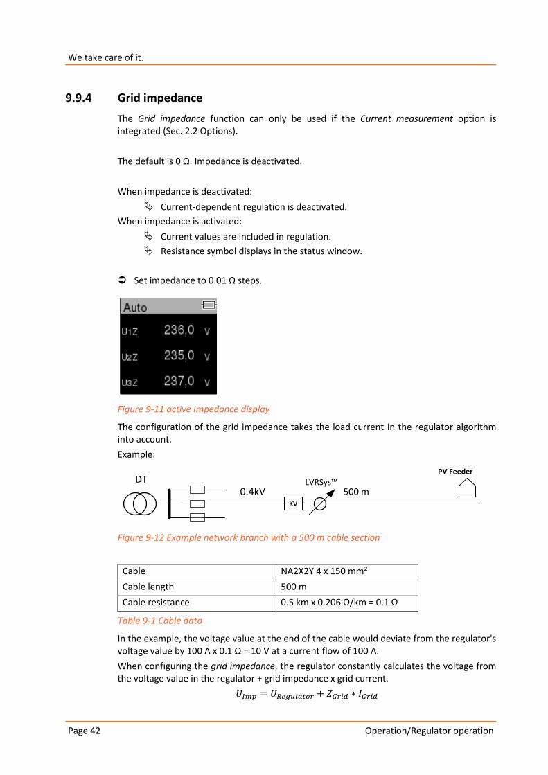
9.9.4 Grid impedance
The Grid impedance function can only be used if the Current measurement option is integrated (Sec. 2.2 Options).
The default is 0 Ω. Impedance is deactivated.
When impedance is deactivated:
Current-dependent regulation is deactivated.
When impedance is activated:
Current values are included in regulation.
Resistance symbol displays in the status window.
Set impedance to 0.01 Ω steps.
Figure 9-11 active Impedance display
The configuration of the grid impedance takes the load current in the regulator algorithm into account.
Example:
0.4kV
PV Feeder
KV
LVRSys™ DT
Figure 9-12 Example network branch with a 500 m cable section
Cable NA2X2Y 4 x 150 mm²
Cable length 500 m
Cable resistance 0.5 km x 0.206 Ω/km = 0.1 Ω
Table 9-1 Cable data
In the example, the voltage value at the end of the cable would deviate from the regulator's voltage value by 100 A x 0.1 Ω = 10 V at a current flow of 100 A.
When configuring the grid impedance, the regulator constantly calculates the voltage from the voltage value in the regulator + grid impedance x grid current.
500 m
Page 43
Operation/Regulator operation
9.9.5 Synchro phasing
Synchro phasing is deactivated by default.
Activating or deactivating synchro phasing
A. Eberle GmbH & Co. KG. recommends activating synchro phasing in systems with bus bars, and deactivating it in systems with strand synchro phasing.
9.10 Setup
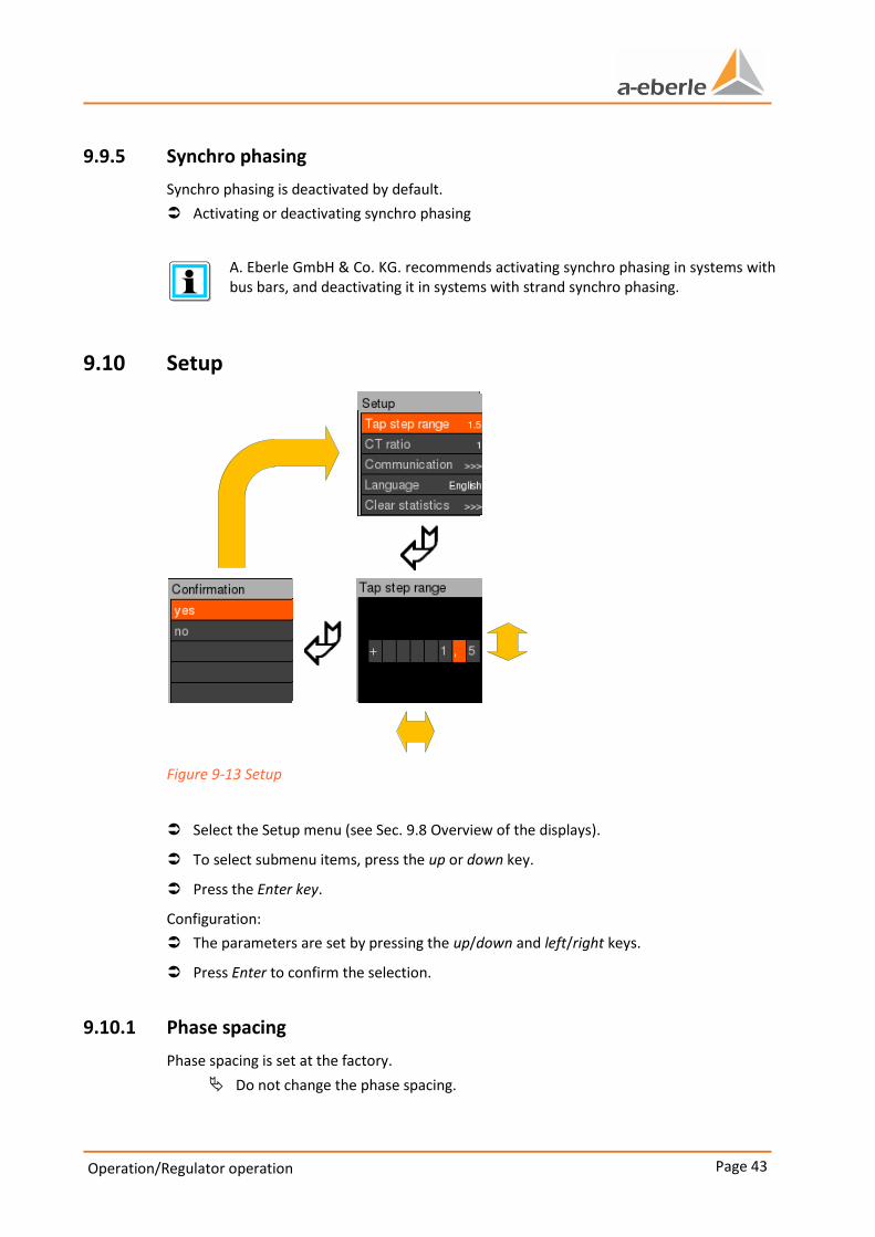
Figure 9-13 Setup
Select the Setup menu (see Sec. 9.8 Overview of the displays).
To select submenu items, press the up or down key.
Press the Enter key.
Configuration:
The parameters are set by pressing the up/down and left/right keys.
Press Enter to confirm the selection.
9.10.1 Phase spacing
Phase spacing is set at the factory.
Do not change the phase spacing.
Operation/Regulator operation Page 44
We take care of it.
9.10.2 KNI (current transformer factor)
For A. Eberle GmbH & Co. KG. current transformers, the transfer ratio is set at the factory.
When external current transformers are used:
Enter the conversion ratio.
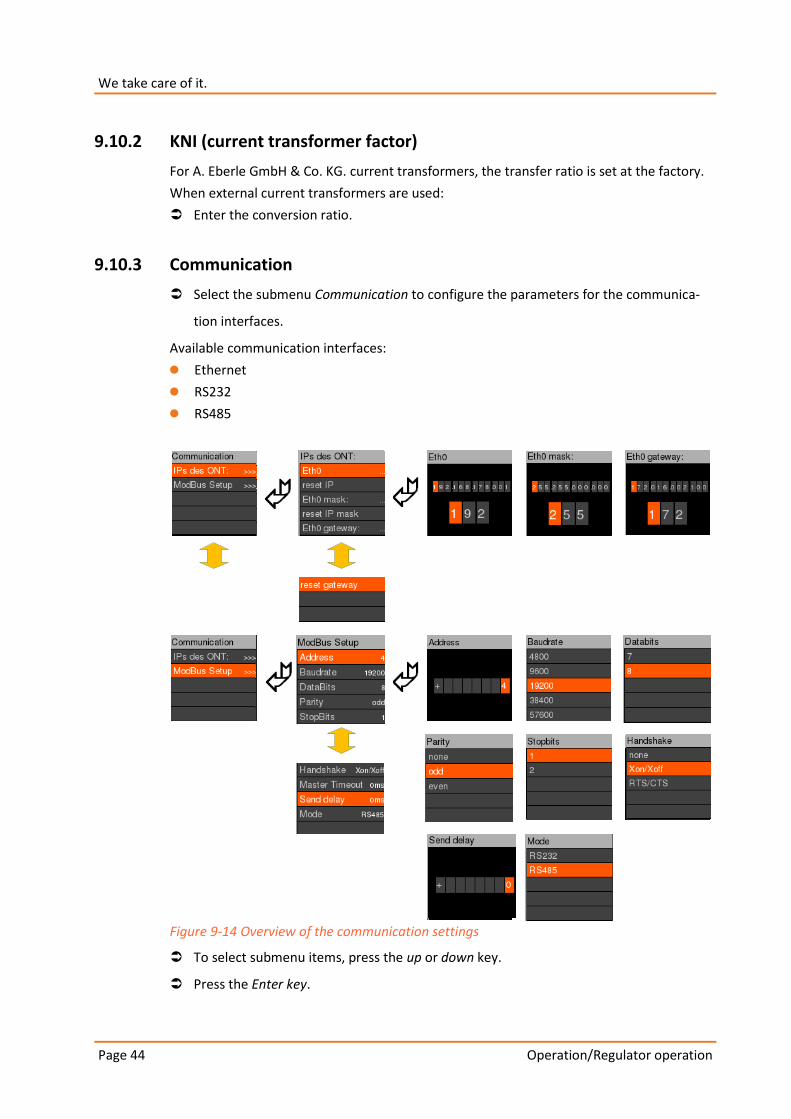
9.10.3 Communication
Select the submenu Communication to configure the parameters for the communica-
tion interfaces.
Available communication interfaces:
0 Ethernet
0 RS232
0 RS485
Figure 9-14 Overview of the communication settings
To select submenu items, press the up or down key.
Press the Enter key.
Page 45
Operation/Regulator operation
Configuration:
The parameters are set by pressing the up/down and left/right keys.
Press Enter to confirm the selection.
Standard parameters for the Modbus Communication are:
0 Address 4
0 Baud rate 19200
0 Data bits 8
0 Parity odd
0 Stop bits 1
0 Handshake Xon/Xoff
0 Transmission delay 0
0 RS232 mode.
9.10.4 Language
Possible languages:
0 German
0 English
9.10.5 Delete statistics
Delete individual statistics:
Select.
Confirm selection.
Selected statistic is deleted.
9.11 Flyback hand
Flyback hand contains 15 min average values for the:
0 maximum voltages (Ph 1-3)
0 maximum currents (Ph 1-3)
0 maximum output values
0 maximum and minimum temperatures in switch cabinet (T 1-3).
– T1: Temperature of the power stage in °C
– T2: Temperature of the transformers in °C
– T3: Temperature of the air in the switch cabinet in °C.
Values can be reset individually.
Resetting the current values also resets the output values.
Operation/Regulator operation Page 46
We take care of it.
9.12 Info/Update
The menu item Info/Update contains:
0 Time
0 Date
0 Firmware version
0 Logbook error entries
0 Run Firmware update
0 Store logbook event.
9.12.1 Firmware update
CAUTION! Destruction of components due to overload!
Make sure the service switch is active before starting the update process.
Activating the service switch isolates the thyristors from the mains voltage and short-circuits the transformers. The control function is out of order. A secure update process can be started.
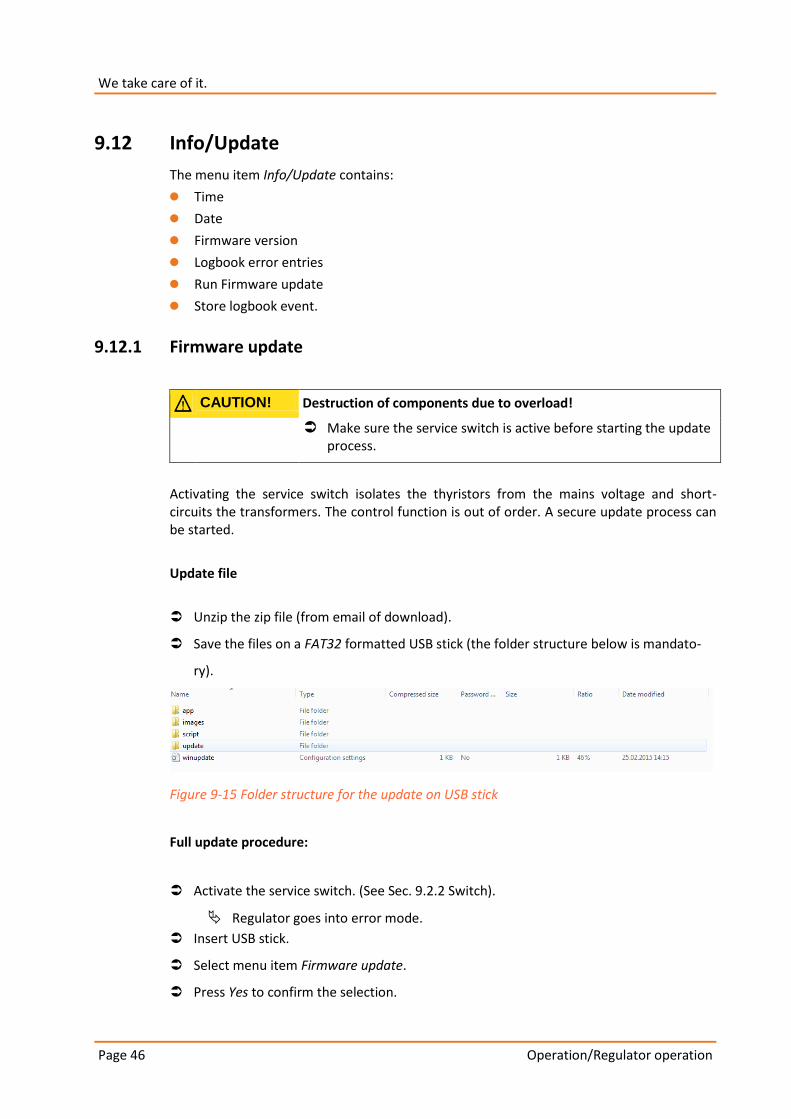
Update file
Unzip the zip file (from email of download).
Save the files on a FAT32 formatted USB stick (the folder structure below is mandato-
ry).
Figure 9-15 Folder structure for the update on USB stick
Full update procedure:
Activate the service switch. (See Sec. 9.2.2 Switch).
Regulator goes into error mode.
Insert USB stick.
Select menu item Firmware update.
Press Yes to confirm the selection.

Page 47
Operation/Regulator operation
Please wait displays.
Do not press any buttons or activate the service switch during the update process.
Regulator needs about 5 minutes for the update process to complete.
The regulator reinitializes.
The regulator stays in error mode when the update is completed.
Deactivate the service switch.
Remove the USB stick.
Regulator goes into automatic mode.
The update procedure is finished.
9.12.2 LOG ERR
The last error is displayed.
Note the error is the installation is malfunctioning.
Contact the A. Eberle GmbH & Co. KG. Support team.
Error code table
Transformer 0x001
Contactor 0x002
Overvoltage 0x004
Under voltage 0x008
Over temperature Channel 1 0x010
Over temperature Channel 2 0x020
Over temperature Channel 3 0x040
EEPROM 0x080
SPI 0x100
Input voltage 0x200
Frequency 0x400
Service switch 0x800
Table 9-2 Error code table
9.12.3 Archive log book
Insert USB stick.
Select menu item Logbook.
Select submenu item Start time.
Data are archived from the start time.
Operation/Regulator operation Page 48
We take care of it.
The data Event data, measurement data, service data must be activated in order to archive them.
0 ( ) Selection inactive
0 (x) Selection active
Select the submenu item Event data, measurement data and service data.
Select with the up or down key.
Press Yes to confirm the selection.
Select the submenu item Archive data.
Press Yes to confirm the selection.
Please wait displays.
Regulator writes data to the USB stick.
Event data contain:
0 Parameters
0 Reparameterization
0 State (Automatic/Manual/Blocked)
0 State changes (Automatic-Manual)
0 Error.
Measurement data
Measurement data contain:
0 U1 to U3 (10 minutes average values in V)
0 I1 to I3 (10 minutes average values in A; only for option Current transformer)
0 P1 to P3 (10 minutes average values in kW; only for option Current transformer)
0 Q1 to Q3 (10 minutes average values in kvar; only for option Current transformer)
0 S1 to S3 (10 minutes average values in kVA; only for option Current transformer)
0 T1 to T3 (10 minutes average values in °C)
0 Tap 1 to Tap 3 (current tap position Ph1-Ph3 at the time)
0 Taps/Period 1-3 (10 minutes average values of tap position Ph1-Ph3).
Service data
Service data are intended solely for the A. Eberle GmbH & Co. KG. support team to perform evaluations.
Page 49
Operation/Regulator operation
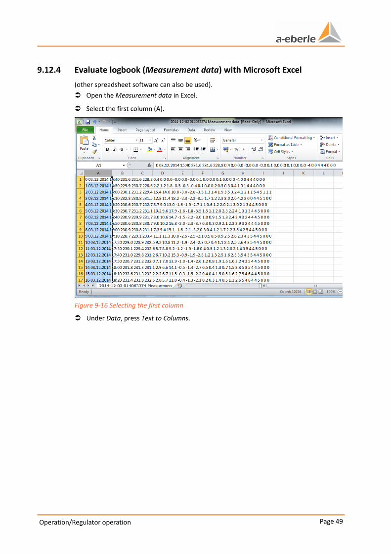
9.12.4 Evaluate logbook (Measurement data) with Microsoft Excel
(other spreadsheet software can also be used).
Open the Measurement data in Excel.
Select the first column (A).
Figure 9-16 Selecting the first column
Under Data, press Text to Columns.

Operation/Regulator operation Page 50
We take care of it.
Figure 9-17 Selecting data and text in columns
Convert Text to Columns Wizard - Step 1 of 3 select Delimited.
Press Next to confirm
Figure 9-18 Text conversion wizard - Step 1 of 3
Page 51
Operation/Regulator operation
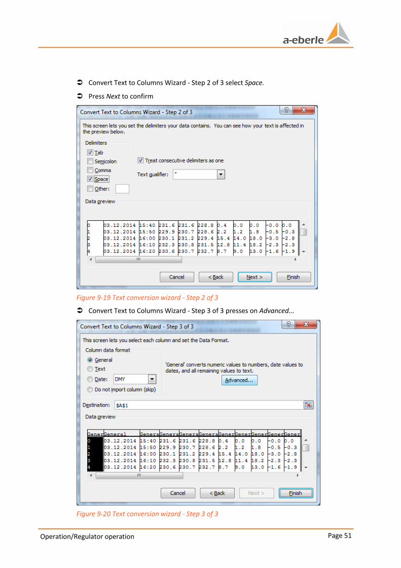
Convert Text to Columns Wizard - Step 2 of 3 select Space.
Press Next to confirm
Figure 9-19 Text conversion wizard - Step 2 of 3
Convert Text to Columns Wizard - Step 3 of 3 presses on Advanced...
Figure 9-20 Text conversion wizard - Step 3 of 3
Operation/Regulator operation Page 52
We take care of it.
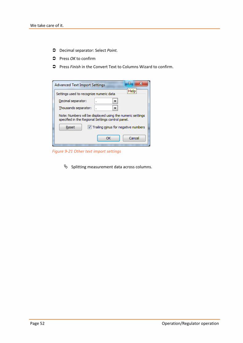
Decimal separator: Select Point.
Press OK to confirm
Press Finish in the Convert Text to Columns Wizard to confirm.
Figure 9-21 Other text import settings
Splitting measurement data across columns.

Page 53
Operation/Regulator operation
9.12.5 Evaluate logbook (Event data) in Notepad++
(other text processing software can also be used).
Figure 9-22 Event data opened in Notepad++

Operation/Regulator operation Page 54
We take care of it.
9.13 Communication
9.13.1 Modbus
Modbus enables the LVRSysTM to be connected to a control system for communication.
Possible Modbus interfaces:
0 RS 232
0 RS 485
0 TCP
Register mapping
Input register (16-Bit data, read only)
Name permitted values Standard Addressing
Status 2 - Operation, 1 - Error 2 101
Table 9-3 Status
Holding registers (16-Bit data, read and write)
Name permitted values Standard Addressing
Operating status 0 - Auto, 1 - Manual, 2 - Blocked 0 201
Ph1 Step up 0/1 1 - Command Step up 0 202
Ph2 Step up 0/1 1 - Command Step up 0 203
Ph3 Step up 0/1 1 - Command Step up 0 204
Ph1 Step up 0/1 1 - Command Step down 0 205
Ph2 Step down 0/1 1 - Command Step down 0 206
Ph3 Step down 0/1 1 - Command Step down 0 207
Delete statistics 0/1 1 - Command Delete statistics 0 208
Reset Flyback hand 0/1 1 - Command Reset Flyback hand
0 209
Table 9-4 Operating status and regulator commands
Input register (16-Bit data, read only)
Name permitted values Unit Addressing
Phase spacing 0 - 1000 0.01 301
Step phase 1 0 - 8 1 302
Step phase 2 0 - 8 1 303
Step phase 3 0 - 8 1 304
Voltage phase 1 0 - 65000 0.1 V 305
Voltage phase 2 0 - 65000 0.1 V 306
Voltage phase 3 0 - 65000 0.1 V 307
Page 55
Operation/Regulator operation
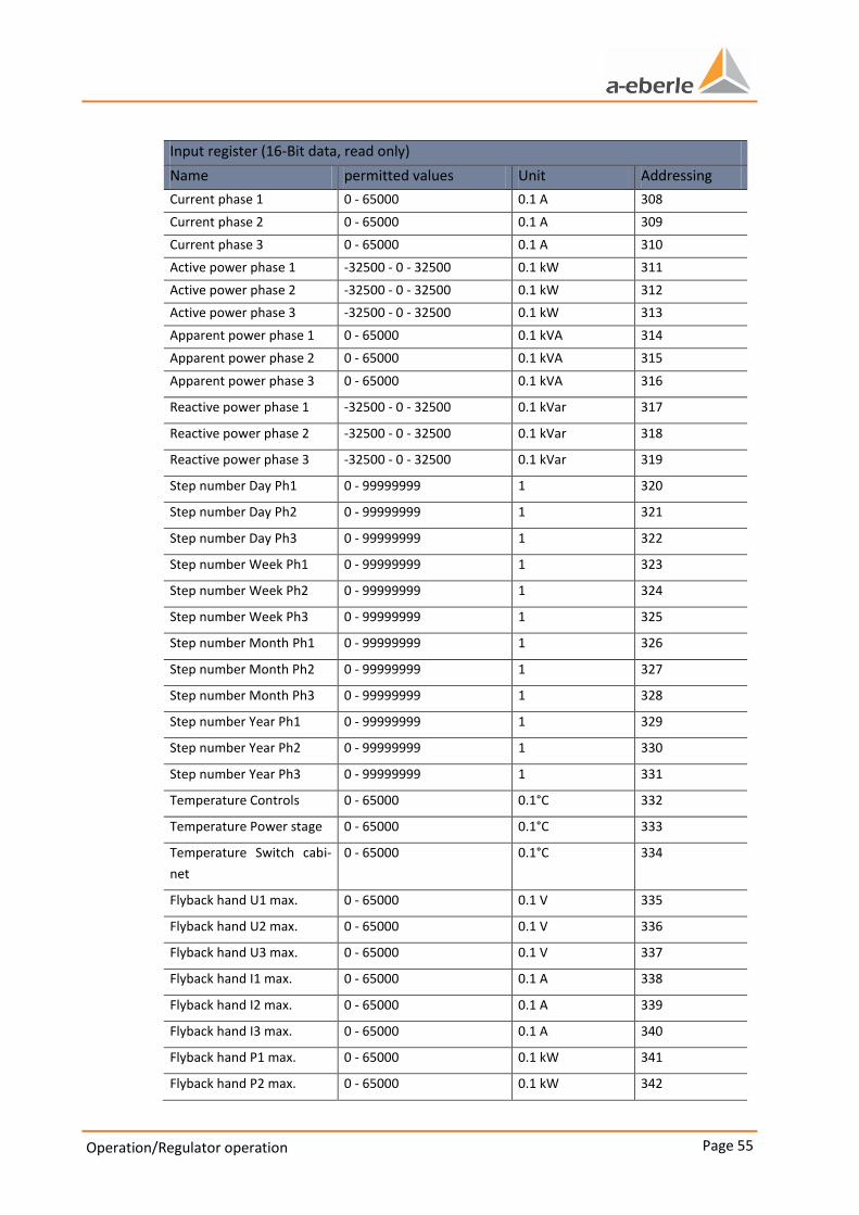
Input register (16-Bit data, read only)
Name permitted values Unit Addressing
Current phase 1 0 - 65000 0.1 A 308
Current phase 2 0 - 65000 0.1 A 309
Current phase 3 0 - 65000 0.1 A 310
Active power phase 1 -32500 - 0 - 32500 0.1 kW 311
Active power phase 2 -32500 - 0 - 32500 0.1 kW 312
Active power phase 3 -32500 - 0 - 32500 0.1 kW 313
Apparent power phase 1 0 - 65000 0.1 kVA 314
Apparent power phase 2 0 - 65000 0.1 kVA 315
Apparent power phase 3 0 - 65000 0.1 kVA 316
Reactive power phase 1 -32500 - 0 - 32500 0.1 kVar 317
Reactive power phase 2 -32500 - 0 - 32500 0.1 kVar 318
Reactive power phase 3 -32500 - 0 - 32500 0.1 kVar 319
Step number Day Ph1 0 - 99999999 1 320
Step number Day Ph2 0 - 99999999 1 321
Step number Day Ph3 0 - 99999999 1 322
Step number Week Ph1 0 - 99999999 1 323
Step number Week Ph2 0 - 99999999 1 324
Step number Week Ph3 0 - 99999999 1 325
Step number Month Ph1 0 - 99999999 1 326
Step number Month Ph2 0 - 99999999 1 327
Step number Month Ph3 0 - 99999999 1 328
Step number Year Ph1 0 - 99999999 1 329
Step number Year Ph2 0 - 99999999 1 330
Step number Year Ph3 0 - 99999999 1 331
Temperature Controls 0 - 65000 0.1°C 332
Temperature Power stage 0 - 65000 0.1°C 333
Temperature Switch cabi-
net
0 - 65000 0.1°C 334
Flyback hand U1 max. 0 - 65000 0.1 V 335
Flyback hand U2 max. 0 - 65000 0.1 V 336
Flyback hand U3 max. 0 - 65000 0.1 V 337
Flyback hand I1 max. 0 - 65000 0.1 A 338
Flyback hand I2 max. 0 - 65000 0.1 A 339
Flyback hand I3 max. 0 - 65000 0.1 A 340
Flyback hand P1 max. 0 - 65000 0.1 kW 341
Flyback hand P2 max. 0 - 65000 0.1 kW 342
Operation/Regulator operation Page 56
We take care of it.
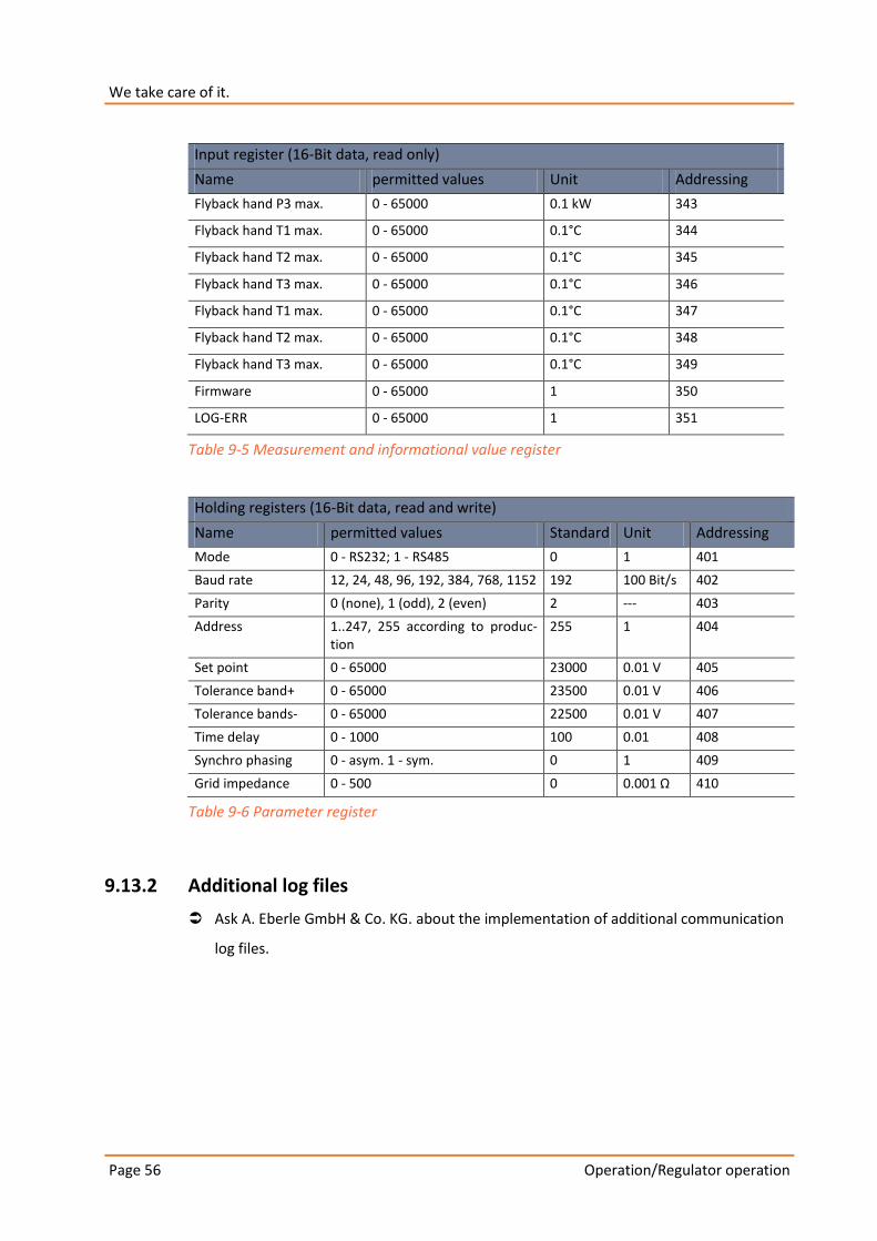
Input register (16-Bit data, read only)
Name permitted values Unit Addressing
Flyback hand P3 max. 0 - 65000 0.1 kW 343
Flyback hand T1 max. 0 - 65000 0.1°C 344
Flyback hand T2 max. 0 - 65000 0.1°C 345
Flyback hand T3 max. 0 - 65000 0.1°C 346
Flyback hand T1 max. 0 - 65000 0.1°C 347
Flyback hand T2 max. 0 - 65000 0.1°C 348
Flyback hand T3 max. 0 - 65000 0.1°C 349
Firmware 0 - 65000 1 350
LOG-ERR 0 - 65000 1 351
Table 9-5 Measurement and informational value register
Holding registers (16-Bit data, read and write)
Name permitted values Standard Unit Addressing
Mode 0 - RS232; 1 - RS485 0 1 401
Baud rate 12, 24, 48, 96, 192, 384, 768, 1152 192 100 Bit/s 402
Parity 0 (none), 1 (odd), 2 (even) 2 --- 403
Address 1..247, 255 according to produc-tion
255 1 404
Set point 0 - 65000 23000 0.01 V 405
Tolerance band+ 0 - 65000 23500 0.01 V 406
Tolerance bands- 0 - 65000 22500 0.01 V 407
Time delay 0 - 1000 100 0.01 408
Synchro phasing 0 - asym. 1 - sym. 0 1 409
Grid impedance 0 - 500 0 0.001 Ω 410
Table 9-6 Parameter register
9.13.2 Additional log files
Ask A. Eberle GmbH & Co. KG. about the implementation of additional communication
log files.
Page 57
Controls and Power stage
10. Controls and Power stage
10.1 Controls
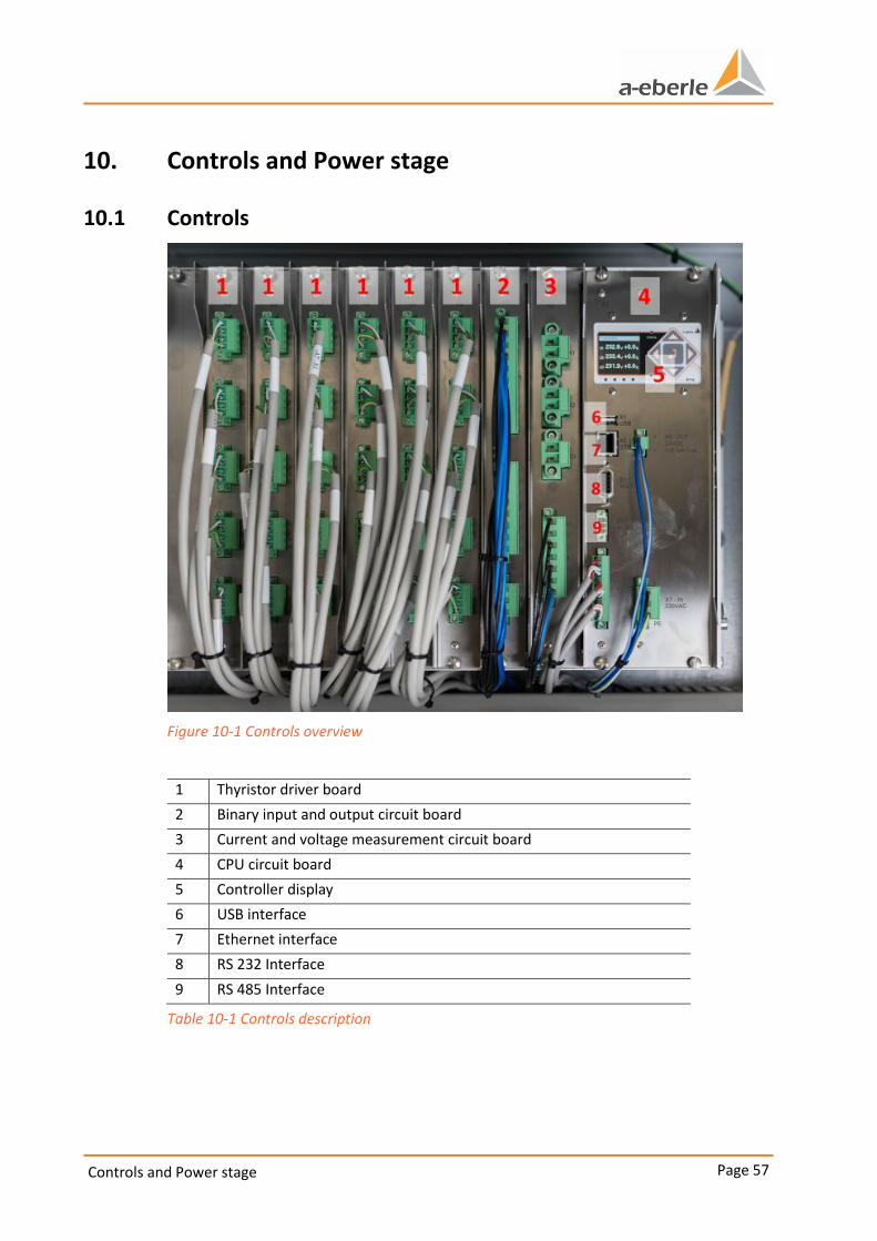
Figure 10-1 Controls overview
1 Thyristor driver board
2 Binary input and output circuit board
3 Current and voltage measurement circuit board
4 CPU circuit board
5 Controller display
6 USB interface
7 Ethernet interface
8 RS 232 Interface
9 RS 485 Interface
Table 10-1 Controls description
Controls and Power stage Page 58
We take care of it.
10.2 Interfaces and log files
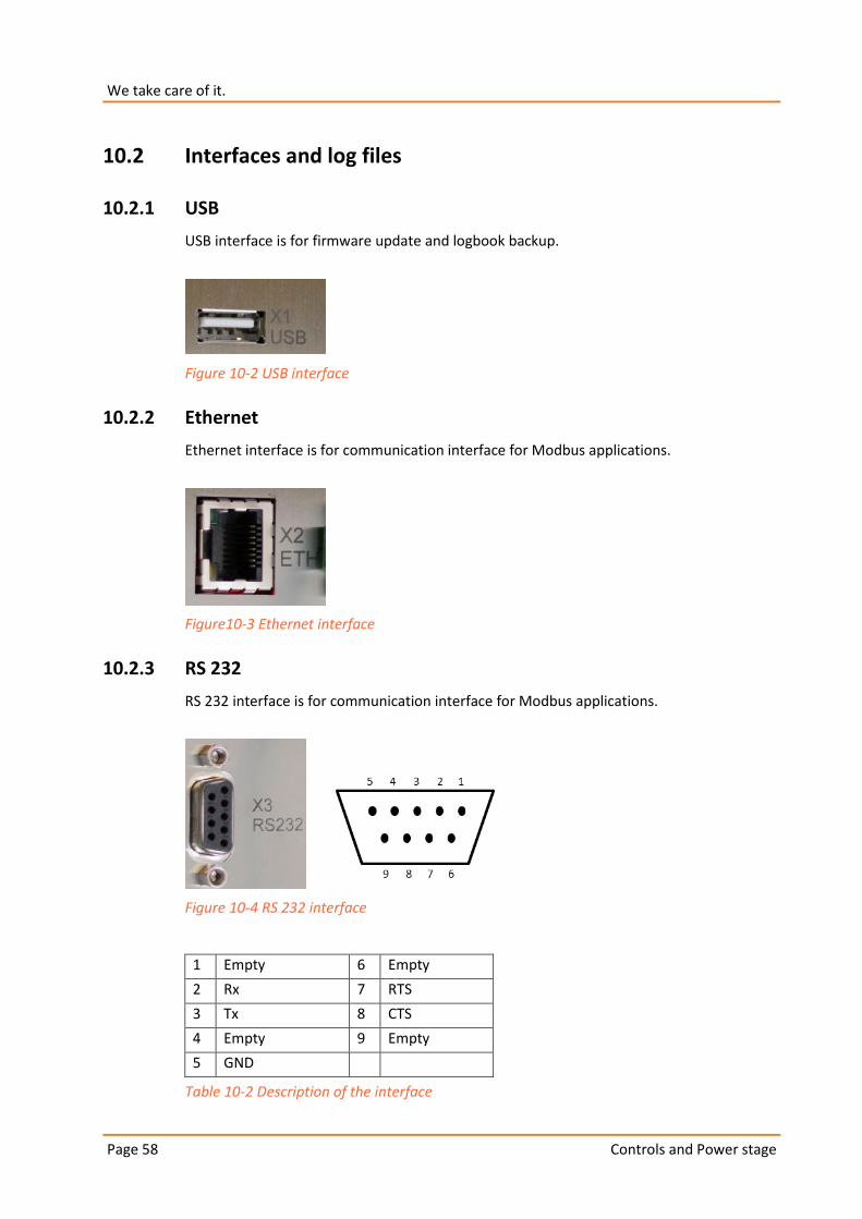
10.2.1 USB
USB interface is for firmware update and logbook backup.
Figure 10-2 USB interface
10.2.2 Ethernet
Ethernet interface is for communication interface for Modbus applications.
Figure10-3 Ethernet interface
10.2.3 RS 232
RS 232 interface is for communication interface for Modbus applications.
Figure 10-4 RS 232 interface
1 Empty 6 Empty
2 Rx 7 RTS
3 Tx 8 CTS
4 Empty 9 Empty
5 GND
Table 10-2 Description of the interface
Page 59
Controls and Power stage
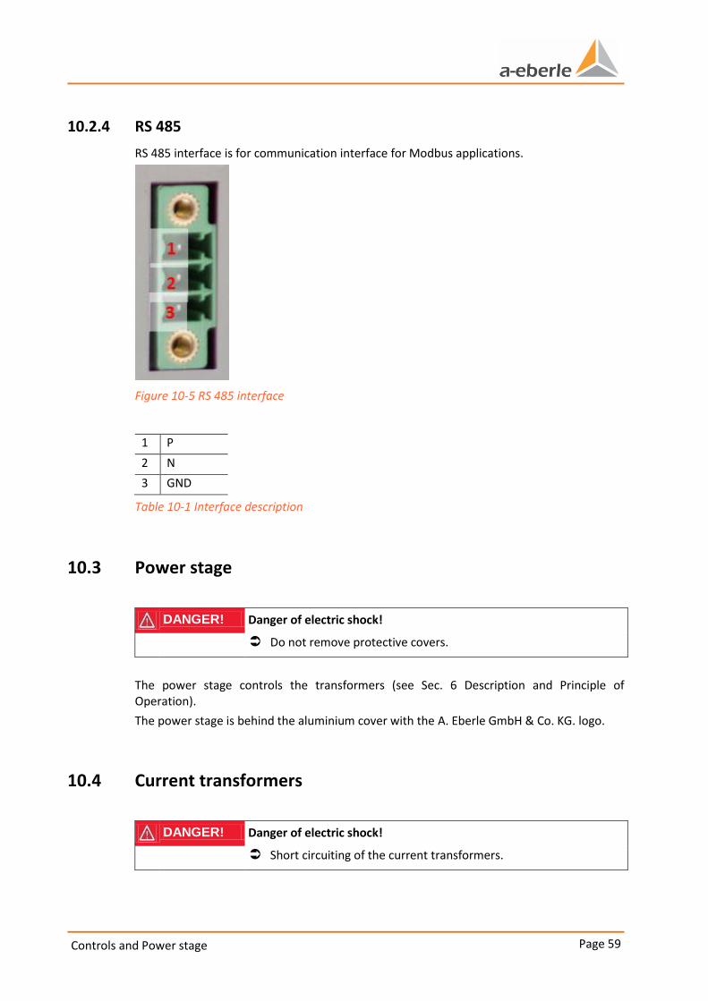
10.2.4 RS 485
RS 485 interface is for communication interface for Modbus applications.
Figure 10-5 RS 485 interface
1 P
2 N
3 GND
Table 10-1 Interface description
10.3 Power stage
DANGER! Danger of electric shock!
Do not remove protective covers.
The power stage controls the transformers (see Sec. 6 Description and Principle of Operation).
The power stage is behind the aluminium cover with the A. Eberle GmbH & Co. KG. logo.
10.4 Current transformers
DANGER! Danger of electric shock!
Short circuiting of the current transformers.
Controls and Power stage Page 60
We take care of it.
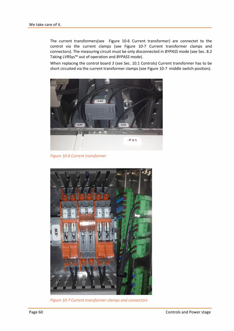
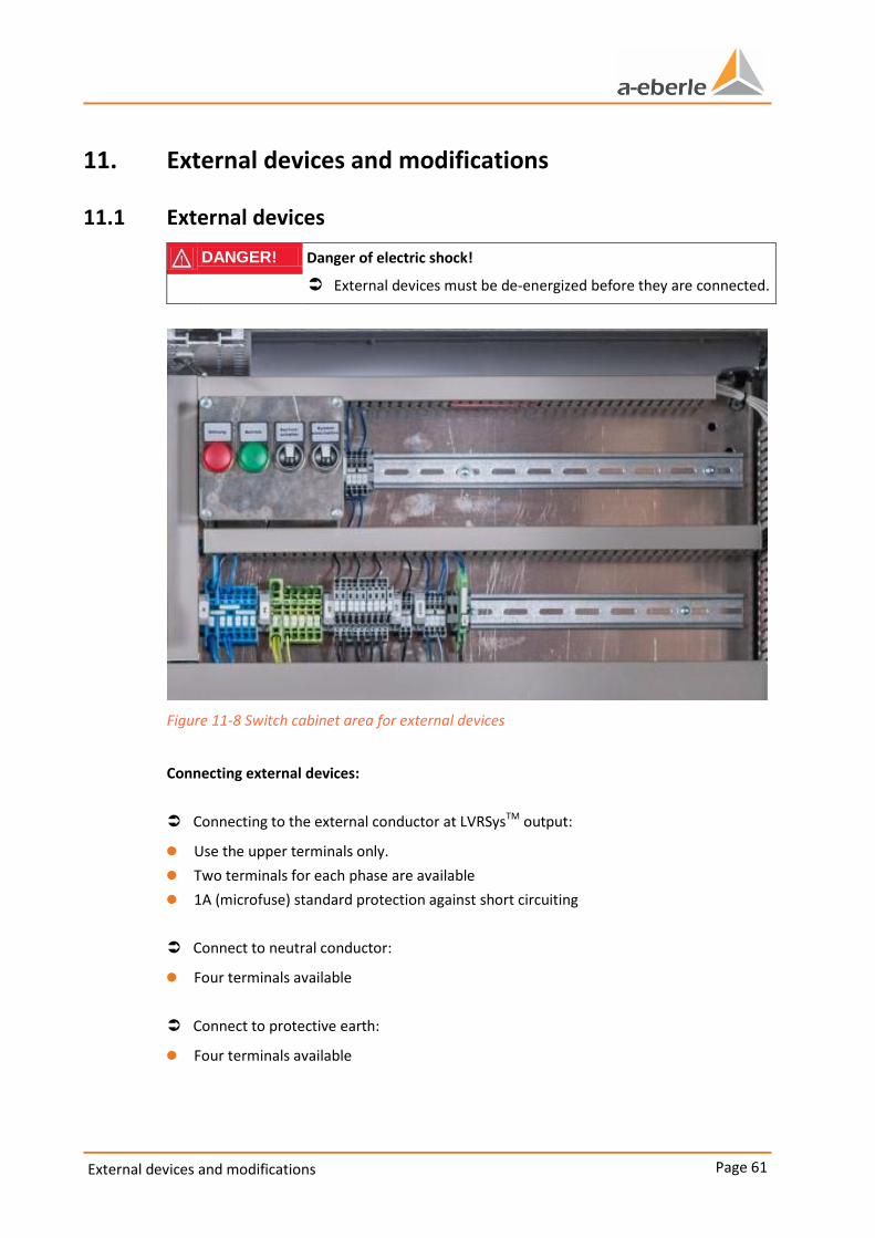
The current transformers(see Figure 10-6 Current transformer) are connectet to the control via the current clamps (see Figure 10-7 Current transformer clamps and connectors). The measuring circuit must be only disconnected in BYPASS mode (see Sec. 8.2 Taking LVRSys™ out of operation and BYPASS mode).
When replacing the control board 3 (see Sec. 10.1 Controls) Current transformer has to be short circuited via the current transformer clamps (see Figure 10-7 middle switch position).
Figure 10-6 Current transformer
Figure 10-7 Current transformer clamps and connectors
Page 61
External devices and modifications
11. External devices and modifications
11.1 External devices
DANGER! Danger of electric shock!
External devices must be de-energized before they are connected.
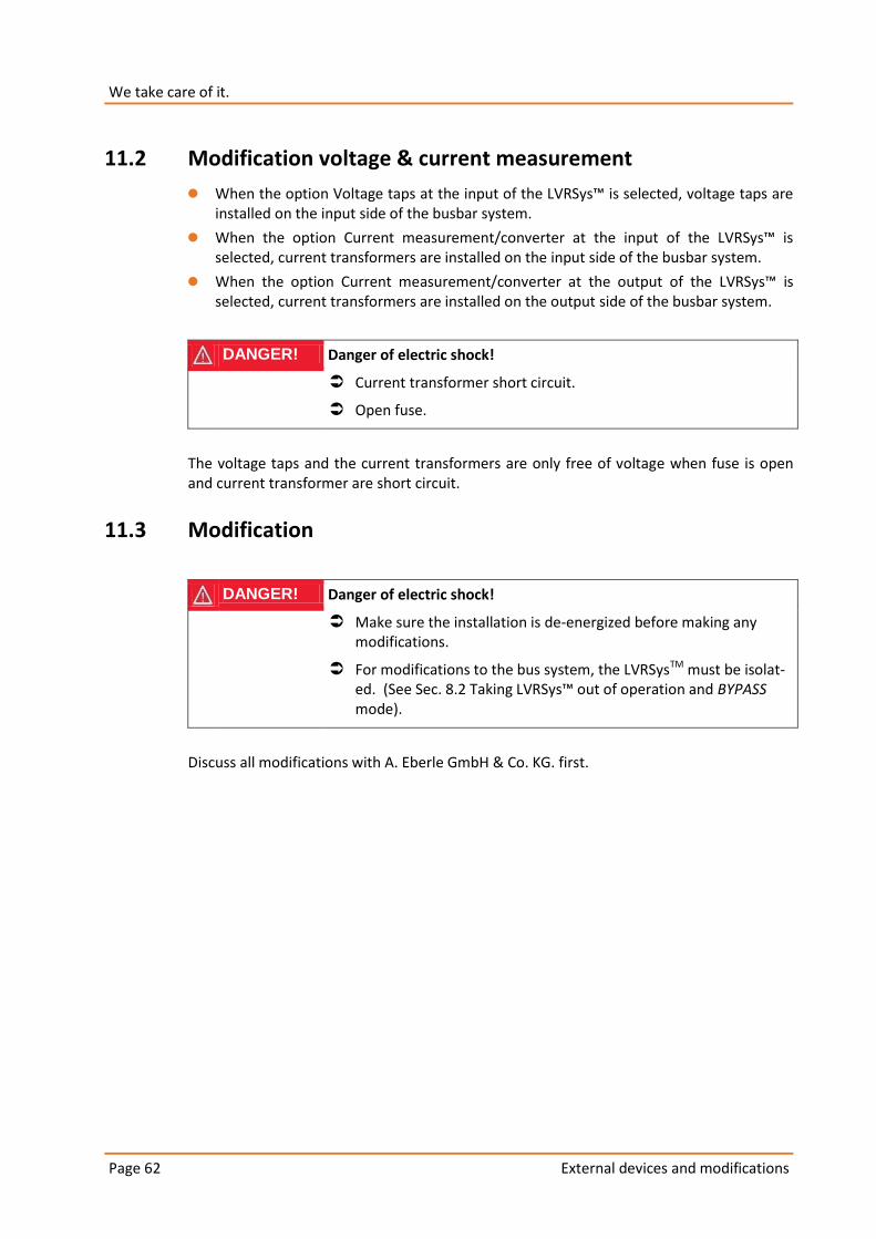
Figure 11-8 Switch cabinet area for external devices
Connecting external devices:
Connecting to the external conductor at LVRSysTM output:
0 Use the upper terminals only.
0 Two terminals for each phase are available
0 1A (microfuse) standard protection against short circuiting
Connect to neutral conductor:
0 Four terminals available
Connect to protective earth:
0 Four terminals available
External devices and modifications Page 62
We take care of it.
11.2 Modification voltage & current measurement
0 When the option Voltage taps at the input of the LVRSys™ is selected, voltage taps are installed on the input side of the busbar system.
0 When the option Current measurement/converter at the input of the LVRSys™ is selected, current transformers are installed on the input side of the busbar system.
0 When the option Current measurement/converter at the output of the LVRSys™ is selected, current transformers are installed on the output side of the busbar system.
DANGER! Danger of electric shock!
Current transformer short circuit.
Open fuse.
The voltage taps and the current transformers are only free of voltage when fuse is open and current transformer are short circuit.
11.3 Modification
DANGER! Danger of electric shock!
Make sure the installation is de-energized before making any modifications.
For modifications to the bus system, the LVRSysTM must be isolat-ed. (See Sec. 8.2 Taking LVRSys™ out of operation and BYPASS mode).
Discuss all modifications with A. Eberle GmbH & Co. KG. first.

Page 63
External devices and modifications
11.4 PQI-DA smart
0 When the option Power quality measurement at LVRSys™ input is selected, voltage taps and current transformer are installed on the input side of the busbar system.
0 When the option Power quality measurement at LVRSys™ output is selected, voltage taps and current transformer are installed on the output side of the busbar system.
DANGER! Danger of electric shock!
Current transformer short circuit.
Open fuse.
The PQI-DA smart are only free of voltage when fuse is open and current transformer are short circuit.
Servicing/Cleaning/Spare parts Page 64
We take care of it.
12. Servicing/Cleaning/Spare parts
0 The service interval depends on the operating and environmental conditions.
0 Service at least once a year.
12.1 Switch cabinet
Hinges:
Make sure the hinges move freely.
If required, spray with non-aqueous lubricant.
Lock:
Make sure the lock moves freely.
If required, spray moving locking pieces and profile cylinder with non-aqueous lubri-
cant.
Door stay hinge:
Check the door stay hinge.
Replace defective door stay hinge.
If required, spray moving point with non-aqueous lubricant.
Surfaces:
Testing and cleaning the ventilation gills in the rain cover.
Check all components and surfaces for external damage and signs of corrosion.
Remove light white rust.
As protection against white rust, treat the surfaces with a lightly oiled cloth.
Clean the switch cabinet.

Page 65
Servicing/Cleaning/Spare parts
Seals:
Check seals.
Replace damaged seals in the pressing edges.
Lubricate seals to prevent freezing (e.g. with talcum, Vaseline, wax).
For small-area damage:
Sand the damaged area lightly and remove all signs of corrosion and dirt.
Apply touch-up paint.
Based on the size of the damage, touch up with:
– Touch-up applicator
– Paint brush
– Spray can of paint.
Alternatively apply 2K-PUR acrylic paint.
Observe the manufacturer's processing instructions.
For large-area damage (e.g. from strong abrasion and UV fading):
Rub the surface evenly and clean with white spirit.
Paint over the whole area with Rittal touch-up paint (alternatively: 2K-PUR acrylic paint;
observe the manufacturer's processing instructions).
Alternatively apply 2K-PUR acrylic paint.
Observe the manufacturer's processing instructions.
User the following RAL 7035 colours:
0 Touch-up applicator 12ml
0 Spray can 150ml
0 Paint can 1000ml.

Servicing/Cleaning/Spare parts Page 66
We take care of it.
12.2 Power stage
DANGER! Danger of electric shock!
Make sure the power stage is de-energized before servicing.
Servicing the power stage:
Press on Thyristor plug contacts.
Check warning signs.
Check contacts. If necessary, tighten (torque under Table 12-1 Power stage compo-
nents).
Installation Contact Torque Figure
55 kVA
110 kVA
175 kVA
250 kVA ±6%
Thyristor for aluminium plate
SKKT 106/18E
Thyristor for copper bus
SKKT 106/18E
M6 5 Nm ±15% (hexagon socket)
M5 3 Nm ±15% (hexagon socket)
250 kVA ±10%
400 kVA ±6%
Thyristor for aluminium plate
SKKT 162/18E
Thyristor for copper bus
SKKT 162/18E
M6 5 Nm ±15% (hexagon socket)
M6 5 Nm ±15% (hexagon socket)
All installations Gate plug-in con-nector
(for the controls)
With flat-blade screwdriver
ca. 5 N clamping pressure
All installations Connections to
transformers and contactors
55 kVA ±6%/±10%
110 kVA ±6%
Main terminals
Coil terminals
(AF 9-22-00)
M3.5 1.5 Nm
M3.5 1.2 Nm
Ø 5.5 Pozidriv 2

Page 67
Servicing/Cleaning/Spare parts
110 kVA ±10%
175kVA ±6%/±10%
250 kVA ±6%
Main terminals
Coil terminals
(AF 26-22-00)
M4.5 2.5 Nm
M3.5 1.2 Nm
Ø 5.5 Pozidriv 2
250 kVA ±10%
400 kVA ±6%
Main terminals
Coil terminals
(A 45-22-00)
M6 4 Nm
Ø 6.5 Pozidriv 2
M3.5 1.2 Nm
Ø 5.5 Pozidriv 2
All installations Surge arrester
DEHNGuard DG S 275FM
M6 4 Nm
Ø 6.5 Pozidriv 2
Table 12-1 Power stage components
Malfunctions to the LVRSys™ may only be fixed by A. Eberle GmbH & Co. KG.
Servicing/Cleaning/Spare parts Page 68
We take care of it.
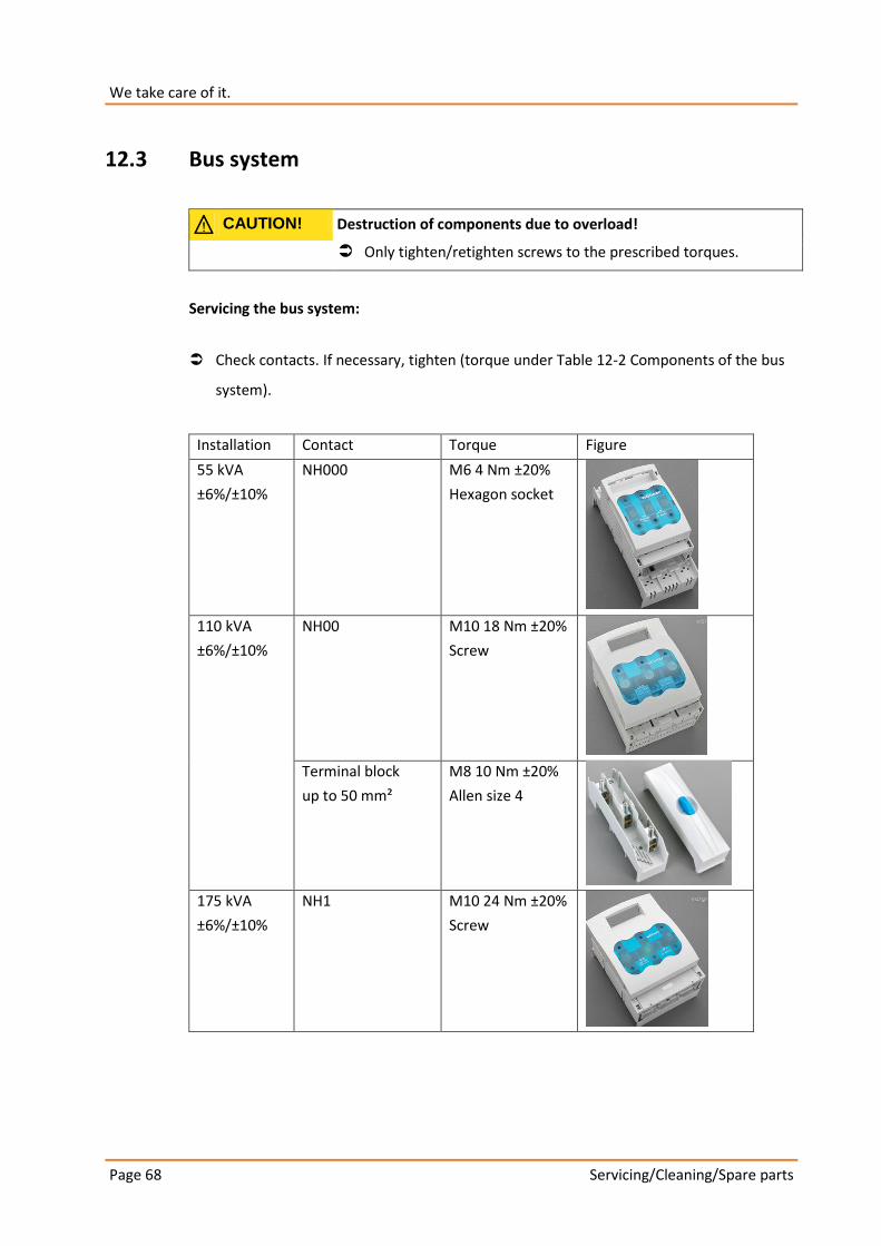
12.3 Bus system
CAUTION! Destruction of components due to overload!
Only tighten/retighten screws to the prescribed torques.
Servicing the bus system:
Check contacts. If necessary, tighten (torque under Table 12-2 Components of the bus
system).
Installation Contact Torque Figure
55 kVA
±6%/±10%
NH000 M6 4 Nm ±20%
Hexagon socket
110 kVA
±6%/±10%
NH00 M10 18 Nm ±20%
Screw
Terminal block
up to 50 mm²
M8 10 Nm ±20%
Allen size 4
175 kVA
±6%/±10%
NH1 M10 24 Nm ±20%
Screw

Page 69
Servicing/Cleaning/Spare parts
Terminal block
up to 120 mm²
M12 15 Nm ±20%
Allen size 4
250 kVA
±6%/±10%
Switch disconnect-or fuse NH2
up to 1 x 240 mm²
M10 32 Nm
400 kVA
±6%
Switch disconnect-or fuse NH3
up to 2 x 240 mm²
M12 32 Nm
Table 12-2 Components of the bus system
Contact A. Eberle GmbH & Co. KG. in the event of malfunctions
Service address:
A. Eberle GmbH & Co. KG
Frankenstraße 160
D-90461 Nuremburg
Telephone: +49 (0)911 628108 – 0
Fax: +49 (0)911 628108 – 96
Email: info@A. Eberle.de
12.4 Spare/Replacement parts
Order replacement parts from manufacturer of A. Eberle GmbH & Co. KG.
The complete product catalogue can be obtained from A. Eberle GmbH & Co. KG.
Servicing/Cleaning/Spare parts Page 70
We take care of it.
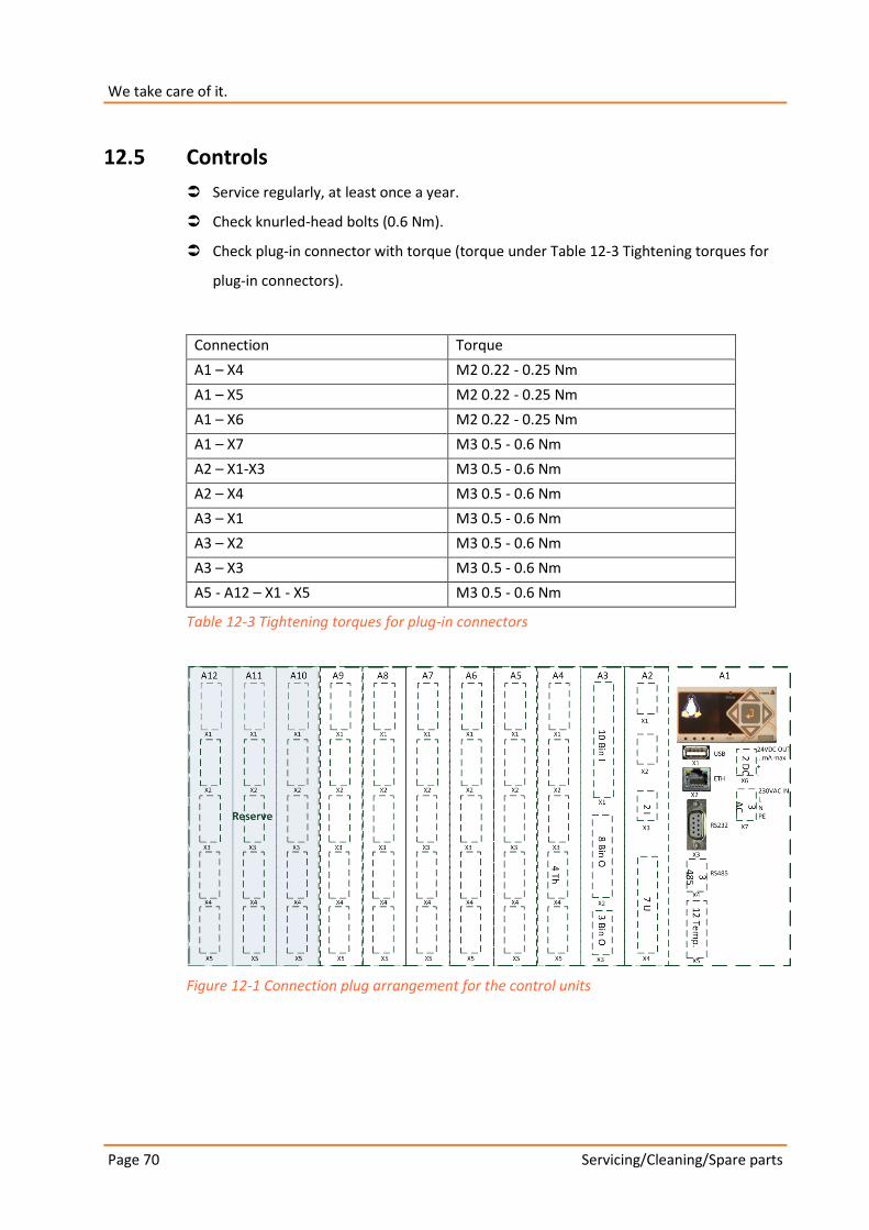
12.5 Controls
Service regularly, at least once a year.
Check knurled-head bolts (0.6 Nm).
Check plug-in connector with torque (torque under Table 12-3 Tightening torques for
plug-in connectors).
Connection Torque
A1 – X4 M2 0.22 - 0.25 Nm
A1 – X5 M2 0.22 - 0.25 Nm
A1 – X6 M2 0.22 - 0.25 Nm
A1 – X7 M3 0.5 - 0.6 Nm
A2 – X1-X3 M3 0.5 - 0.6 Nm
A2 – X4 M3 0.5 - 0.6 Nm
A3 – X1 M3 0.5 - 0.6 Nm
A3 – X2 M3 0.5 - 0.6 Nm
A3 – X3 M3 0.5 - 0.6 Nm
A5 - A12 – X1 - X5 M3 0.5 - 0.6 Nm
Table 12-3 Tightening torques for plug-in connectors
Figure 12-1 Connection plug arrangement for the control units

Page 71
Standards and Laws
13. Standards and Laws
LVD 2014/35/EU
DIN EN 61439-1 Low-voltage switchgear and controlgear assemblies - Part 1: General rules
DIN EN 61439-5 Low-voltage switchgear and controlgear assemblies - Part 5: Assemblies for power distribution in public networks
DIN EN 0298-4 Application of cables and cords in power installations - Part 4: Recommended current-carrying capacity for sheathed and non-sheathed cables for fixed wirings in buildings and for flexible cables and cords
DIN EN 61000-6-1 Electromagnetic compatibility (EMC) - Part 6-1: Generic standards - Immunity for residential, commercial and light-industrial environments
DIN EN 61000-6-3 Electromagnetic compatibility (EMC) - Part 6-3: Generic standards - Emission standard for residential, commercial and light-industrial environments
DIN EN 50160 Voltage characteristics of electricity supplied by public distribution networks
DIN EN 82079-1 Preparation of instructions for use - Structuring, content and presentation - Part 1: General principles and detailed requirements

Disassembly and disposal Page 72
We take care of it.
14. Disassembly and disposal
DANGER! Danger of electric shock!
Make sure the LVRSys™ is de-energized before disassembling it.
Make sure the LVRSys™ is de-energized
Remove low voltage cable.
Remove local cabinet grounding.
The disposal of the LVRSys™ will be carried out by A. Eberle GmbH & Co. KG..
All components are to be sent to:
A. Eberle GmbH & Co. KG
Frankenstraße 160
D-90461 Nuremburg
15. Guarantee
A. Eberle GmbH & Co. KG. guarantees that this product and accessories will remain free of defects in material and workmanship for a period of three years from the date of purchase.
This warranty does not cover damage caused by:
0 accidents
0 misuse
0 abnormal operating conditions
To make a claim under this warranty, please contact A. Eberle GmbH & Co KG in Nuremburg, Germany.

Notes
Page 73
Notes

A. Eberle GmbH & Co. KG
Frankenstraße 160
D-90461 Nuremberg
Tel.: +49 (0) 911/62 81 08-0
Fax: +49 (0) 911/62 81 08 96
Email: [email protected]
http://www.a-eberle.de
Edition of: 25/02/2015
Copyright 2015 A. Eberle GmbH & Co. KG
Subject to change without prior notice.


![A New Paradigm for the Sociology of Knowledge [Eberle]](https://img.dokumen.tips/doc/110x75/577cbfc41a28aba7118e0a17/a-new-paradigm-for-the-sociology-of-knowledge-eberle.jpg)