Embed Size (px)
Citation preview
User and Maintenance Manualfor the Homeowner
andInstallation Instructions
for the Contractor
ACU-STEAM™
Humidifi erby Thermolec
Please read this manual carefully before beginning installation.
Important Notice to the Contractor :
Once the installation is complete, please leave this manual with the customer for future reference.
July 2010 V1.0
!

CO
NTR
AC
TOR
Page 1
1. Warnings and Disclaimer – Installation Precautions
Please read and understand the warnings and instructions fully before you begin this installation and keep them handy for future reference.The manufacturer will assume no responsibility and the warranty will be void if the installer or the user does not adhere to the following precautions :
1.1 This humidifi er will be connected to and used under water pressure and it must be installed in such a way that if a leak occurs, the water could not cause any damage to the property. Make sure all water connections are properly installed or a water leak could occur.
1.3 Do not install a humidifi er where the surrounding temperature may be 32ºF (0ºC) or colder. Freezing water will damage the humidifi er and burst the supply pipe, resulting in home damage.
1.6 Do not install a humidifi er if the city water pressure exceeds 90 psi. Check the local codes related to pressure reduction.
1.8 The installation, wiring and plumbing of the humidifi er must comply with national and local electrical, plumbing and building codes.
1.9 Electrical wiring and water tubes must not come in contact with sharp edges or hot surfaces.1.10 Make certain an appropriate drain system is installed and there is no resistance to the fl ow of the
discharged water.1.11 Do not set the humidity level higher than that recommended or condensation damage will occur.1.13 Always shut the power off before you start the installation or when doing maintenance. An electric
shock from 120 or 240 volts could cause serious injury.1.14 When you perform maintenance, please be careful because the unit can be extremely hot. Always
allow enough time for the unit to cool down.1.15 To prevent electric shock or injuries, never operate the humidifi er without the cover as there are high
voltage and hot components inside.1.16 This humidifi er will only work with non demineralized water. The maximum water supply temperature is
86 ºF (30 ºC)
HO
ME
OW
NER
HO
ME
OW
NER
Page 2
Instructions and User Manual for the Homeowner
2. View of the unit
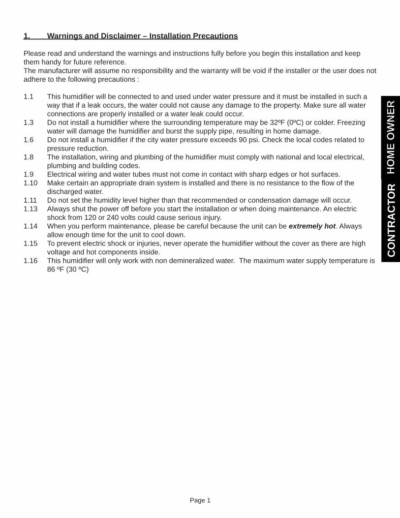
2.1 External view of the humidifi er. Fig. 2a
2.2 Water Tank Top View. Please see Fig. 2b.
2.3 Water tank Side View. Please see Fig. 2c.
!
Fig. 2c
Fig. 2b
HO
ME
OW
NER
HO
ME
OW
NER
Page 3
3. Startup
3.1 The startup of the humidifi er is done in as follows : Put the main power ON at the electrical panel. The green pilot light comes ON. The humidifi er is ready to work. Open the water supply valve. Adjust the knob on the humidistat.
Working Principle :
3.2 Unlike other types of humidifi ers which produce humidity by passing warm air on a water curtain, a rotating pad or another type of media, this humidifi er produces humidity from steam dispersed directly into the air.
3.3 A humidistat installed on the wall controls the unit. You set the knob of the humidistat according to your need or comfort. Please read the next section about the humidity control.
3.4 When the humidistat senses a need for humidity, it starts the humidifi cation process.
3.5 The tank fi lls with water.
3.6 The electronic control starts the fan to move the air as the humidifi er starts boiling water and producing steam. If the fan cannot start (i.e. there is no air movement to transport the steam or insuffi cient air pressure), the humidifi er stops itself. Please note that it may take a few minutes to bring the water to a boil. The steam exits the water tank through the steam hose, moves to the steam diffuser installed in the fan module and is spread into the room.
3.7 As water evaporates, the electric valve opens as needed to replenish the water in the tank.
3.8 When the humidity reaches the desired level, the humidifi er stops producing steam and automatically drains. In order to eliminate the residues and keep the tank as clean as possible, the humidifi er also drains after a certain number of boiling / refi ll cycles. If there is still a demand from the humidistat after draining, the tank refi lls and starts to produce steam again. This process is part of the self-cleaning feature.
3.9 When the humidistat is satisfi ed, the fan continues to run for a short period of time in order to eliminate the steam from the ducts and the unit goes to ready mode, waiting for the next call from the humidistat.
HO
ME
OW
NER
HO
ME
OW
NER
Page 4
4. How to Control the Humidity
4.1 Humidity level and comfort are personal matters but it is generally acknowledged that a Relative Humidity of 35-40% is desirable. However, you should take the outside temperature into consideration before setting the humidity level in order to avoid condensation on the windows. Usually, a narrow strip of condensation around or at the bottom of the window is considered as normal.
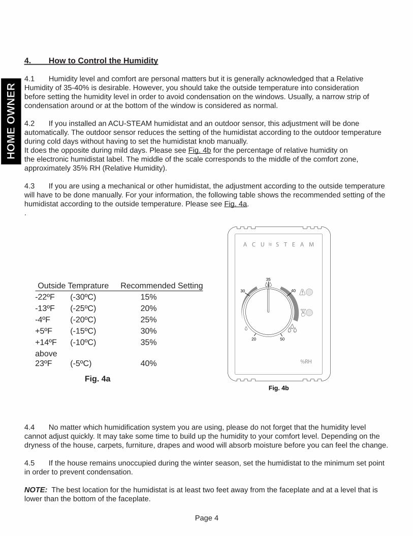
4.2 If you installed an ACU-STEAM humidistat and an outdoor sensor, this adjustment will be done automatically. The outdoor sensor reduces the setting of the humidistat according to the outdoor temperature during cold days without having to set the humidistat knob manually.It does the opposite during mild days. Please see Fig. 4b for the percentage of relative humidity on the electronic humidistat label. The middle of the scale corresponds to the middle of the comfort zone, approximately 35% RH (Relative Humidity).
4.3 If you are using a mechanical or other humidistat, the adjustment according to the outside temperature will have to be done manually. For your information, the following table shows the recommended setting of the humidistat according to the outside temperature. Please see Fig. 4a..
4.4 No matter which humidifi cation system you are using, please do not forget that the humidity level cannot adjust quickly. It may take some time to build up the humidity to your comfort level. Depending on the dryness of the house, carpets, furniture, drapes and wood will absorb moisture before you can feel the change.
4.5 If the house remains unoccupied during the winter season, set the humidistat to the minimum set point in order to prevent condensation.
NOTE: The best location for the humidistat is at least two feet away from the faceplate and at a level that is lower than the bottom of the faceplate.
Fig. 4b
!
35
30
20
40
50
Outside Temprature Recommended Setting-22ºF (-30ºC) 15%-13ºF (-25ºC) 20%-4ºF (-20ºC) 25%+5ºF (-15ºC) 30%+14ºF (-10ºC) 35%above 23ºF (-5ºC) 40%
Fig. 4a
HO
ME
OW
NER
HO
ME
OW
NER
Page 5
5. Functions of the Electronic Circuit
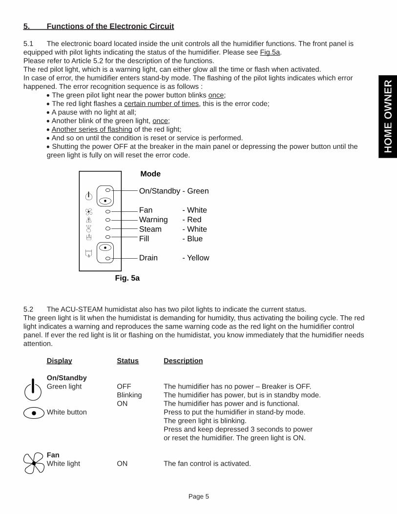
5.1 The electronic board located inside the unit controls all the humidifi er functions. The front panel is equipped with pilot lights indicating the status of the humidifi er. Please see Fig.5a.Please refer to Article 5.2 for the description of the functions.The red pilot light, which is a warning light, can either glow all the time or fl ash when activated.In case of error, the humidifi er enters stand-by mode. The fl ashing of the pilot lights indicates which error happened. The error recognition sequence is as follows : The green pilot light near the power button blinks once; The red light fl ashes a certain number of times, this is the error code; A pause with no light at all; Another blink of the green light, once; Another series of fl ashing of the red light; And so on until the condition is reset or service is performed. Shutting the power OFF at the breaker in the main panel or depressing the power button until the green light is fully on will reset the error code.
5.2 The ACU-STEAM humidistat also has two pilot lights to indicate the current status.The green light is lit when the humidistat is demanding for humidity, thus activating the boiling cycle. The red light indicates a warning and reproduces the same warning code as the red light on the humidifi er control panel. If ever the red light is lit or fl ashing on the humidistat, you know immediately that the humidifi er needs attention.
Display Status Description
On/Standby Green light OFF The humidifi er has no power – Breaker is OFF. Blinking The humidifi er has power, but is in standby mode. ON The humidifi er has power and is functional. White button Press to put the humidifi er in stand-by mode. The green light is blinking. Press and keep depressed 3 seconds to power or reset the humidifi er. The green light is ON.
Fan White light ON The fan control is activated.
!
On/Standby - Green
FanWarningSteamFill
Drain
- White- Red- White- Blue
- Yellow
Fig. 5a
Mode
HO
ME
OW
NER
HO
ME
OW
NER
Page 6
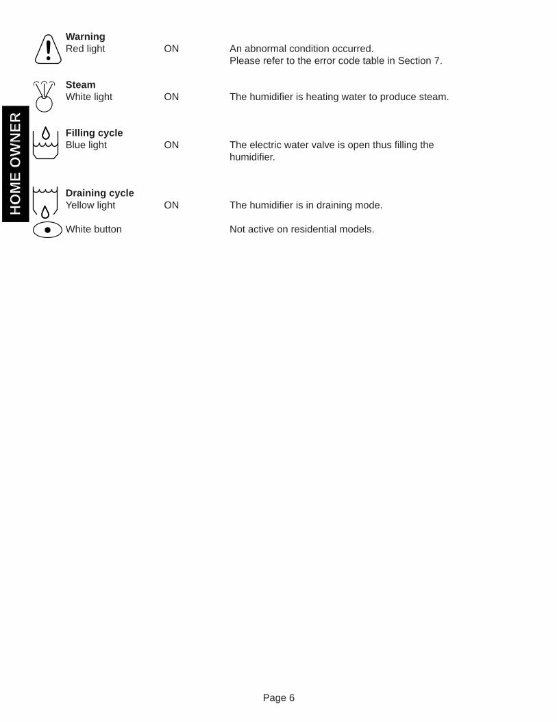
Warning Red light ON An abnormal condition occurred. Please refer to the error code table in Section 7. Steam White light ON The humidifi er is heating water to produce steam.
Filling cycle Blue light ON The electric water valve is open thus fi lling the humidifi er.
Draining cycle Yellow light ON The humidifi er is in draining mode. White button Not active on residential models.
!
HO
ME
OW
NER
HO
ME
OW
NER
Page 7
6. What To Do if a Malfunction Occurs
6.1 Shut the main power OFF and restart the humidifi er to see if the error code disappears.
6.2 If you see a water leak, follow the water supply tube and close the valve installed on the water pipe located near the humidifi er.
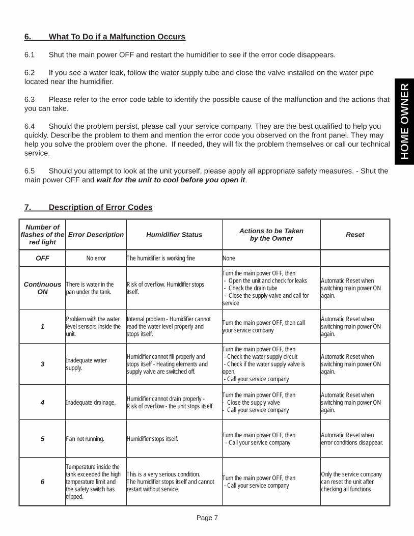
6.3 Please refer to the error code table to identify the possible cause of the malfunction and the actions that you can take.
6.4 Should the problem persist, please call your service company. They are the best qualifi ed to help you quickly. Describe the problem to them and mention the error code you observed on the front panel. They may help you solve the problem over the phone. If needed, they will fi x the problem themselves or call our technical service.
6.5 Should you attempt to look at the unit yourself, please apply all appropriate safety measures. - Shut the main power OFF and wait for the unit to cool before you open it.
7. Description of Error Codes
Number of fl ashes of the
red lightError Description Humidifi er Status Actions to be Taken
by the Owner Reset
OFF No error The humidifi er is working fi ne None
Continuous ON
There is water in the pan under the tank.
Risk of overfl ow. Humidifi er stops itself.
Turn the main power OFF, then - Open the unit and check for leaks - Check the drain tube - Close the supply valve and call for service
Automatic Reset when switching main power ON again.
1Problem with the water level sensors inside the unit.
Internal problem - Humidifi er cannot read the water level properly and stops itself.
Turn the main power OFF, then call your service company
Automatic Reset when switching main power ON again.
3 Inadequate water supply.
Humidifi er cannot fi ll properly and stops itself - Heating elements and supply valve are switched off.
Turn the main power OFF, then - Check the water supply circuit - Check if the water supply valve is open. - Call your service company
Automatic Reset when switching main power ON again.
4 Inadequate drainage. Humidifi er cannot drain properly - Risk of overfl ow - the unit stops itself.
Turn the main power OFF, then - Close the supply valve - Call your service company
Automatic Reset when switching main power ON again.
5 Fan not running. Humidifi er stops itself. Turn the main power OFF, then - Call your service company
Automatic Reset when error conditions disappear.
6
Temperature inside the tank exceeded the high temperature limit and the safety switch has tripped.
This is a very serious condition. The humidifi er stops itself and cannot restart without service.
Turn the main power OFF, then - Call your service company
Only the service company can reset the unit after checking all functions.
HO
ME
OW
NER
HO
ME
OW
NER

Page 8
8. Cleaning the tank
As with any device evaporating water, some minerals normally dissolved in the water may create deposits inside of the unit. Even though the unit is draining and cleaning itself during normal operation , it will require a bit of maintenance from time to time.
WARNING : The water tank and its contents can become extremely hot. Please be careful when you handle it. The tank may have water inside.
8.1 Since the tank is drained when the demand of the humidistat has been satisfi ed, there should be approximately one inch of water if the unit is not operating. But if the humidistat is calling for steam and the water is boiling, turn down the humidistat. The humidifi er will stop and drain. Please note that when using an ACU-STEAM electronic humidistat, if the relative humidity is extremely low the humidifi er may still run with the knob at the minimum setting because of a range limiter inside the cover. If this occurs you will need to remove the humidistat cover by pulling it off and turn the knob completely counter-clockwise. The humidifi er should now stop and drain. Wait until the unit has cooled before proceeding with the following steps.
8.2 Before doing anything, TURN THE MAIN POWER OFF.
8.3 Remove the cover by turning the two 1/4 turn screws to the left.
8.4 Unplug the white quick connect wire connected on the water pan at the bottom of the unit. This wire is connected to the overfl ow sensor. Please see Fig. 8a.
White Wire
Main drain Tube
Overflow Pan
1. Lift2. Pull
OverflowDrain Tube
Rigid Drain Pipe
Overflow Sensor
Fig. 8a
HO
ME
OW
NER
HO
ME
OW
NER
Page 9
8.5 Pull the plastic tube attached to the bottom of the unit out of the rigid drain pipe on the wall. You do not have to remove the plastic tube attached to the bottom of the pan. Remove the overfl ow pan from the unit by slightly loosening the front screw then lifting the front of the pan off the screw and pulling it towards you. Please see Fig. 8a. Remove the main drain tube from the rigid drain pipe attached to the wall and check that they are both clean and clear from deposits.
8.6 Check that the water tank is not too hot to handle. Unfasten the latch around the water tank and remove the tank from the main body of the humidifi er by pulling it down. When you remove the tank, it is possible to clean the round o-ring gasket, but don’t discard it.NOTE :This round gasket is mandatory and the unit will not work properly without it.
8.7 Soap or vinegar can be used to clean the water tank, the heating element and the tips of the level sensors. Other cleaning products used to remove scale, lime or calcium are also available on the market, but DO NOT use a metal brush or any strong acids to clean the tank as they may damage the stainless steel.
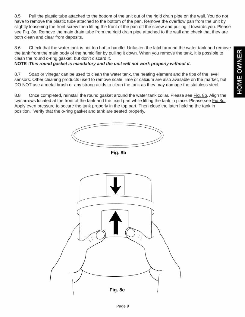
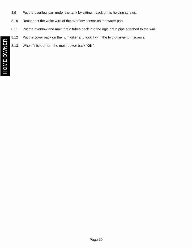
8.8 Once completed, reinstall the round gasket around the water tank collar. Please see Fig. 8b. Align the two arrows located at the front of the tank and the fi xed part while lifting the tank in place. Please see Fig.8c. Apply even pressure to secure the tank properly in the top part. Then close the latch holding the tank in position. Verify that the o-ring gasket and tank are seated properly.
Fig. 8b
Fig. 8c
HO
ME
OW
NER
HO
ME
OW
NER
Page 10
8.9 Put the overfl ow pan under the tank by sitting it back on its holding screws.
8.10 Reconnect the white wire of the overfl ow sensor on the water pan.
8.11 Put the overfl ow and main drain tubes back into the rigid drain pipe attached to the wall.
8.12 Put the cover back on the humidifi er and lock it with the two quarter-turn screws.
8.13 When fi nished, turn the main power back “ON”.
HO
ME
OW
NER
HO
ME
OW
NER
Page 11
9. Preventative Maintenance
9.1 Preventive maintenance to be performed every two years.In order to avoid problems due to accumulation of deposits, we suggest that you replace the centre metal tube, the silicone drain tube and the low level sensor. We also suggest you replace the round o-ring gasket around the tank. All these components are available in a kit.
9.2 To prepare for the Summer Season Shut the main power OFF Shut the water supply valve Perform a complete maintenance as described in section 8 Dry the inside of the tank
HO
ME
OW
NER
HO
ME
OW
NER
Page 12
10. Warranty
10.1 Thermolec Ltd. warrants against defects in material and workmanship the steam humidifi er and all its components for one (1) year after date of shipment from its factory.
10.2 Any claim under this warranty shall be considered only if the product has been installed and operated in accordance with Thermolec’s written instructions.
10.3 Any misuse of the system or any repair by persons other than those authorized by Thermolec, carried out without its written consent, voids this warranty.
10.4 Thermolec responsibility shall be limited in any case to the replacement or repair, in its factory or in the fi eld, by its own personnel or by others chosen by Thermolec, at its option, of such steam humidifi er or parts thereof, as shall prove to be defective within the warranty period.
10.5 Thermolec Ltd. will not be held responsible for accidental or consequential damages, nor for delays, nor for damages caused by the replacement of the said defective steam humidifi er.
Thermolec Ltd2060 Lucien-Thimens St. Montreal, QC, H4R 1L1
Tel : 514-336-9130 Fax : 514-336-3270
Help line for technical assistance during business hoursMonday to Friday, 8:30am to 5:00 pm (Eastern Time)
1-800-336-9130
Web site : www.thermolec.com
HO
ME
OW
NER
HO
ME
OW
NER
CO
NTR
AC
TOR
Page 13
Detailed Instructions for the Contractor
11. Unpacking the Unit
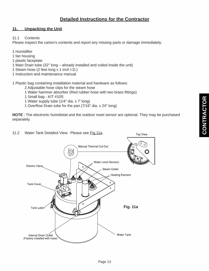
11.1 ContentsPlease inspect the carton’s contents and report any missing parts or damage immediately.
1 Humidifi er1 fan housing1 plastic faceplate1 Main Drain tube (32” long – already installed and coiled inside the unit)1 Steam hose (2 feet long x 1 inch I.D.)1 Instruction and maintenance manual
1 Plastic bag containing installation material and hardware as follows: 2 Adjustable hose clips for the steam hose 1 Water hammer absorber (Red rubber hose with two brass fi ttings) 1 Small bag - KIT #10S 1 Water supply tube (1/4” dia. x 7’ long) 1 Overfl ow Drain tube for the pan (7/16” dia. x 24” long) NOTE : The electronic humidistat and the outdoor reset sensor are optional. They may be purchased separately.
11.2 Water Tank Detailed View. Please see Fig.11a.
Fig. 11a
CO
NTR
AC
TOR
Page 14
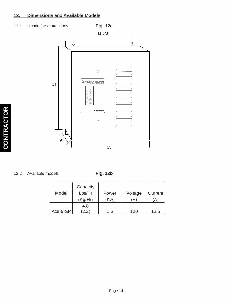
12. Dimensions and Available Models
12.1 Humidifi er dimensions Fig. 12a
12.2 Available models Fig. 12b
14”
13”
11 5/8”
9”
!
CapacityModel Lbs/Hr Power Voltage Current
(Kg/Hr) (Kw) (V) (A)
Acu-5-SP4.8
(2.2) 1.5 120 12.5
CO
NTR
AC
TOR
Page 15
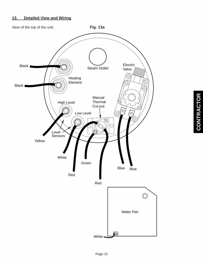
13. Detailed View and Wiring
View of the top of the unit. Fig. 13a
Green
Yellow
White
Red
Red
Black
Black
Blue Blue
HeatingElement
ElectricValveSteam Outlet
LevelSensors
High Level
Low Level
ManualThermalCut-out
Water Pan
White
CO
NTR
AC
TOR
Page 16
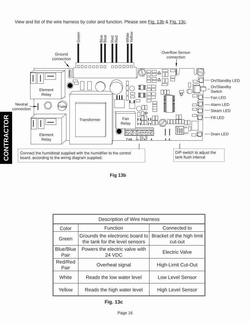
View and list of the wire harness by color and function. Please see Fig. 13b & Fig. 13c.
FANG IN24V
AH-STAT A A
ON
1 2 3 OFF
ON
Gre
en
Blu
eB
lue
Red
Red
Whi
teYe
llow
Fig 13b
FanRelay
ElementRelay
ElementRelay
Transformer
Fuse
Overflow Sensorconnection
On/StandbySwitch
On/Standby LED
Fan LED
Alarm LEDSteam LED
Fill LED
Drain LED
Groundconnection
Neutralconnection
Description of Wire Harness
Color Function Connected to
Green Grounds the electronic board to the tank for the level sensors
Bracket of the high limit cut-out
Blue/BluePair
Powers the electric valve with 24 VDC Electric Valve
Red/RedPair Overheat signal High-Limit Cut-Out
White Reads the low water level Low Level Sensor
Yellow Reads the high water level High Level Sensor
Fig. 13c
CO
NTR
AC
TOR
Page 17
Note: Please read sections 14 and 15 before proceeding.
14. Installing the Steam Hose and the Fan module
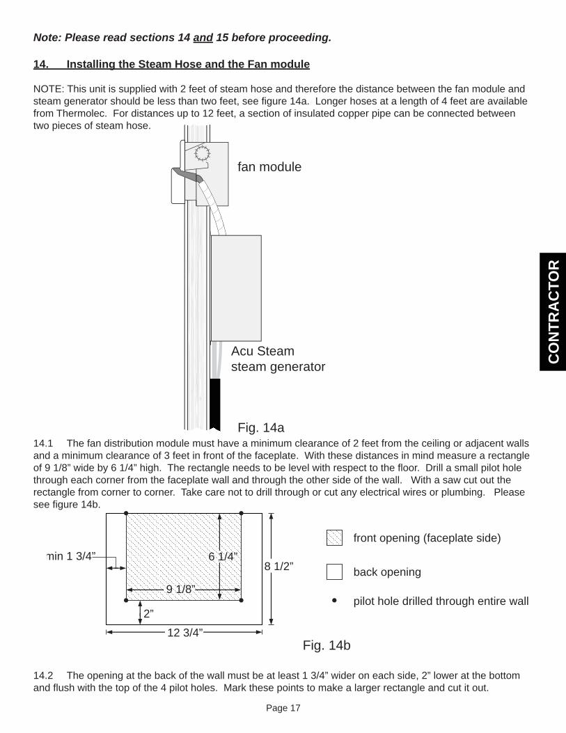
NOTE: This unit is supplied with 2 feet of steam hose and therefore the distance between the fan module and steam generator should be less than two feet, see fi gure 14a. Longer hoses at a length of 4 feet are available from Thermolec. For distances up to 12 feet, a section of insulated copper pipe can be connected between two pieces of steam hose.
14.1 The fan distribution module must have a minimum clearance of 2 feet from the ceiling or adjacent walls and a minimum clearance of 3 feet in front of the faceplate. With these distances in mind measure a rectangle of 9 1/8” wide by 6 1/4” high. The rectangle needs to be level with respect to the fl oor. Drill a small pilot hole through each corner from the faceplate wall and through the other side of the wall. With a saw cut out the rectangle from corner to corner. Take care not to drill through or cut any electrical wires or plumbing. Please see fi gure 14b.
14.2 The opening at the back of the wall must be at least 1 3/4” wider on each side, 2” lower at the bottom and fl ush with the top of the 4 pilot holes. Mark these points to make a larger rectangle and cut it out.
fan module
Acu Steamsteam generator
Fig. 14a
8 1/2”
front opening (faceplate side)
back opening
pilot hole drilled through entire wall
12 3/4”
9 1/8”
2”
min 1 3/4”
Fig. 14b
6 1/4”

CO
NTR
AC
TOR
Page 18
14.3 Attached the mounting fl anges to the fan module with the screws provided but do not tighten the screws so that the fl anges are able to slide along the slots. Slide the fan module into the wall until the front edge is fl ush with the wall, fi gure 14c. Tighten the screws holding the tabs so that the front remains fl ush with the wall. Level the unit and screw the fl anges to the wall.
14.4 Push the faceplate on the front until is snaps into place. Check to be sure that the faceplate completely covers the opening in the wall.
Once the steam generator is installed, connect the steam hose between the difuser in the fan module and the tank in the steam generator with the clamps provided and wire the fan module according to the wiring diagram near the end of this booklet.
flush
Fig. 14c
CO
NTR
AC
TOR
Page 19
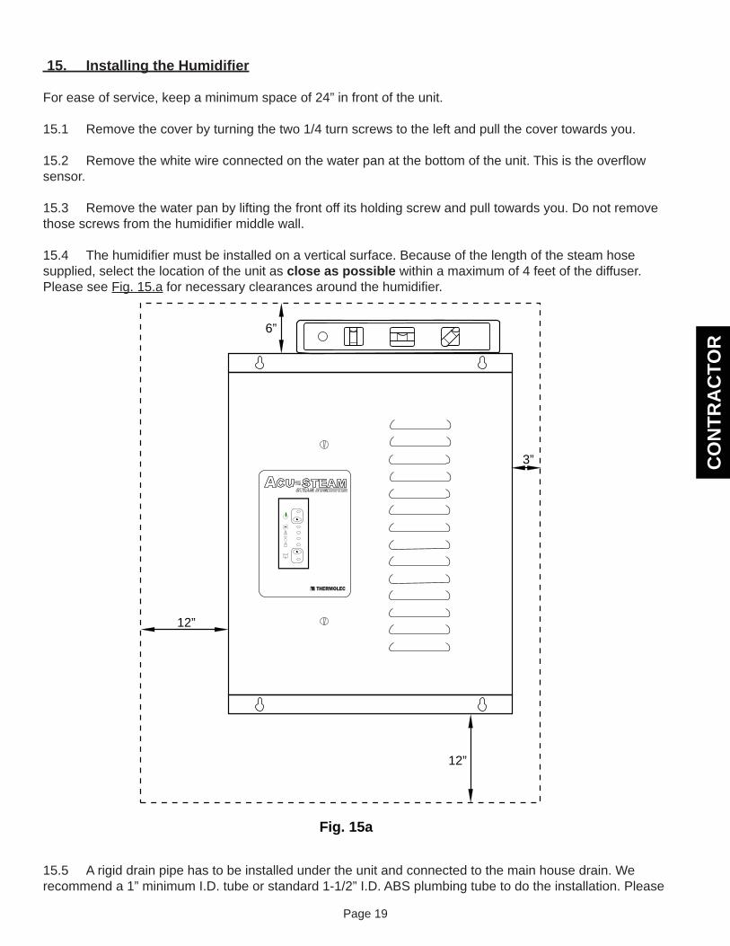
15. Installing the Humidifi er
For ease of service, keep a minimum space of 24” in front of the unit.
15.1 Remove the cover by turning the two 1/4 turn screws to the left and pull the cover towards you.
15.2 Remove the white wire connected on the water pan at the bottom of the unit. This is the overfl ow sensor.
15.3 Remove the water pan by lifting the front off its holding screw and pull towards you. Do not remove those screws from the humidifi er middle wall.
15.4 The humidifi er must be installed on a vertical surface. Because of the length of the steam hose supplied, select the location of the unit as close as possible within a maximum of 4 feet of the diffuser.Please see Fig. 15.a for necessary clearances around the humidifi er.
15.5 A rigid drain pipe has to be installed under the unit and connected to the main house drain. We recommend a 1” minimum I.D. tube or standard 1-1/2” I.D. ABS plumbing tube to do the installation. Please
!
12”
6”
3”
12”
Fig. 15a
CO
NTR
AC
TOR
Page 20
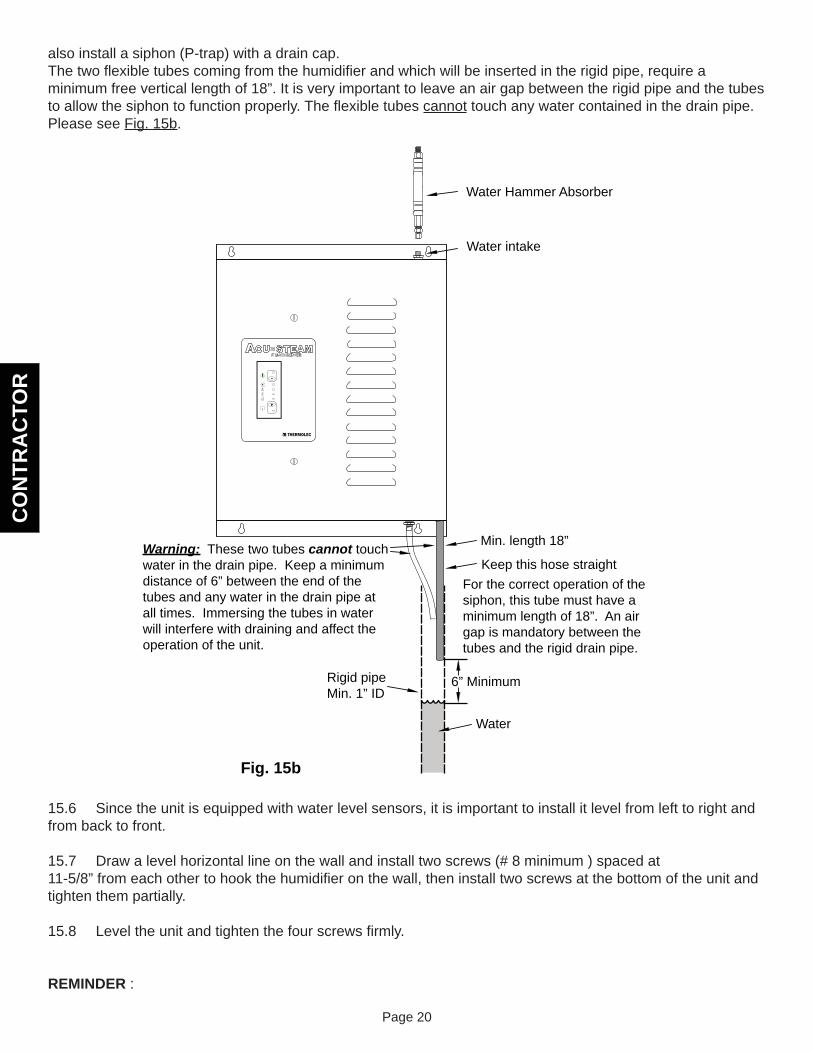
also install a siphon (P-trap) with a drain cap.The two fl exible tubes coming from the humidifi er and which will be inserted in the rigid pipe, require a minimum free vertical length of 18”. It is very important to leave an air gap between the rigid pipe and the tubes to allow the siphon to function properly. The fl exible tubes cannot touch any water contained in the drain pipe. Please see Fig. 15b.
15.6 Since the unit is equipped with water level sensors, it is important to install it level from left to right and from back to front.
15.7 Draw a level horizontal line on the wall and install two screws (# 8 minimum ) spaced at11-5/8” from each other to hook the humidifi er on the wall, then install two screws at the bottom of the unit and tighten them partially.
15.8 Level the unit and tighten the four screws fi rmly.
REMINDER :
!
Water Hammer Absorber
Water intake
Min. length 18”
Keep this hose straight
Rigid pipeMin. 1” ID
Fig. 15b
For the correct operation of the siphon, this tube must have a minimum length of 18”. An air gap is mandatory between the tubes and the rigid drain pipe.
6” Minimum
Water
Warning: These two tubes cannot touch water in the drain pipe. Keep a minimum distance of 6” between the end of the tubes and any water in the drain pipe at all times. Immersing the tubes in water will interfere with draining and affect the operation of the unit.
CO
NTR
AC
TOR
Page 21
Never install the humidifi er directly on the furnace body as this could void your furnace warranty.16. Installing the Water Supply
Important Notes : Turn off the main water supply before beginning. The supply valve (not supplied) must be attached to a cold water pipe only, close to the humidifi er. Since the unit is draining hot water, cold water is added to reduce the temperature before sending the water to the drain. We recommend installing a quarter of a turn shut off valve (not supplied) near the unit. In case of well water or other water containing particles, we also recommend installing a little strainer in the water line to protect the solenoid valve.
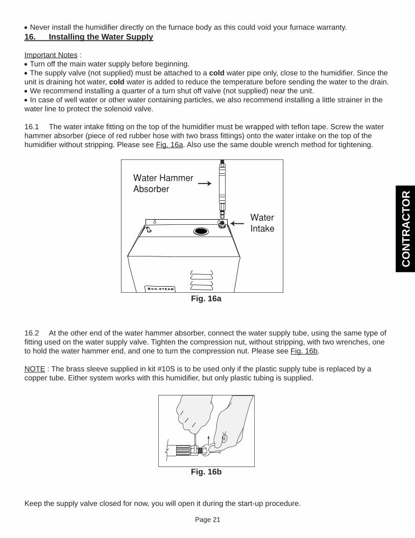
16.1 The water intake fi tting on the top of the humidifi er must be wrapped with tefl on tape. Screw the water hammer absorber (piece of red rubber hose with two brass fi ttings) onto the water intake on the top of the humidifi er without stripping. Please see Fig. 16a. Also use the same double wrench method for tightening.
16.2 At the other end of the water hammer absorber, connect the water supply tube, using the same type of fi tting used on the water supply valve. Tighten the compression nut, without stripping, with two wrenches, one to hold the water hammer end, and one to turn the compression nut. Please see Fig. 16b.
NOTE : The brass sleeve supplied in kit #10S is to be used only if the plastic supply tube is replaced by a copper tube. Either system works with this humidifi er, but only plastic tubing is supplied.
Keep the supply valve closed for now, you will open it during the start-up procedure.
Fig. 16a
Fig. 16b
CO
NTR
AC
TOR
Page 22
18. Making Electrical Connections
NOTE : All internal wiring is done at the factory. All external wiring shall be done by a qualifi ed electrician and must conform to procedures, regulations and local codes.
18.1 A dedicated breaker in the main panel (or fused disconnect) must be installed.
18.2 The voltage of the available power supply must be the same as the one required by the humidifi er.
18.3 Ensure that the wire size and protection equipment conform to the sizes required by the Electrical Code.
18.4 Wire according to the wiring diagram supplied in the cover of the unit.
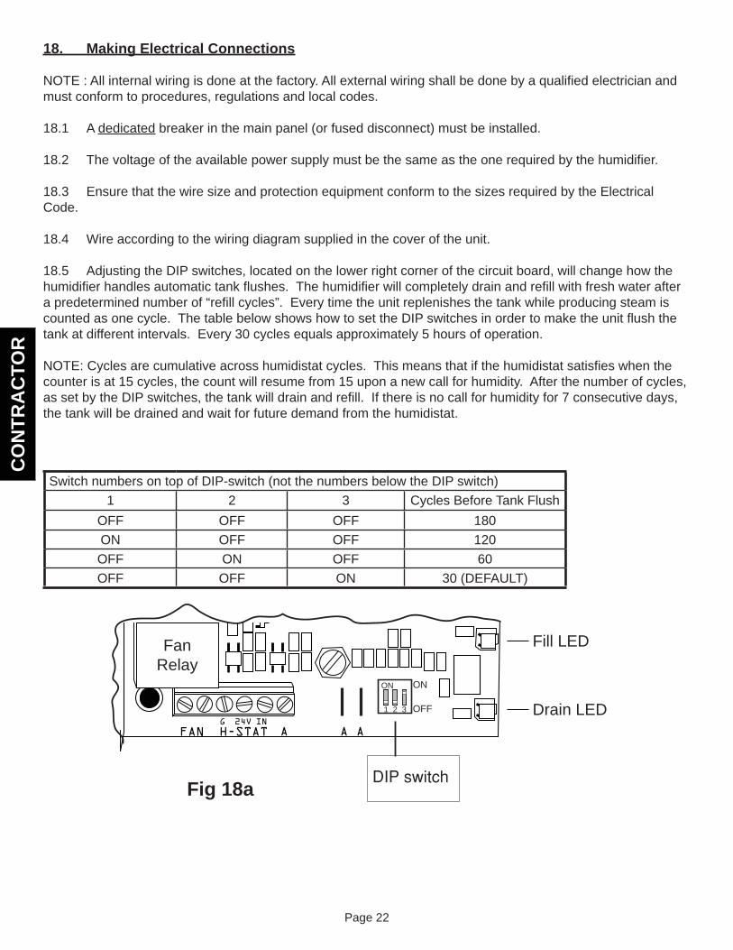
18.5 Adjusting the DIP switches, located on the lower right corner of the circuit board, will change how the humidifi er handles automatic tank fl ushes. The humidifi er will completely drain and refi ll with fresh water after a predetermined number of “refi ll cycles”. Every time the unit replenishes the tank while producing steam is counted as one cycle. The table below shows how to set the DIP switches in order to make the unit fl ush the tank at different intervals. Every 30 cycles equals approximately 5 hours of operation.
NOTE: Cycles are cumulative across humidistat cycles. This means that if the humidistat satisfi es when the counter is at 15 cycles, the count will resume from 15 upon a new call for humidity. After the number of cycles, as set by the DIP switches, the tank will drain and refi ll. If there is no call for humidity for 7 consecutive days, the tank will be drained and wait for future demand from the humidistat.
Switch numbers on top of DIP-switch (not the numbers below the DIP switch)
1 2 3 Cycles Before Tank FlushOFF OFF OFF 180ON OFF OFF 120OFF ON OFF 60OFF OFF ON 30 (DEFAULT)
Fig 18a
FANG IN24V
AH-STAT A A
FanRelay
Fill LED
Drain LEDON
1 2 3 OFF
ON
CO
NTR
AC
TOR
Page 23
19. Installing and Connecting the Humidistat
19.1 See wiring diagrams in section 21 for proper connection. If you are using an ACU-STEAM electronic humidistat with outdoor sensor please refer to the instructions included with the humidistat. If you decide to use a standard mechanical humidistat, connect the mechanical humidistat between the terminals marked GND (ground) & IN (input) on the humidifi er electronic board.
CO
NTR
AC
TOR
Page 24
20. Start-up and Test Procedure
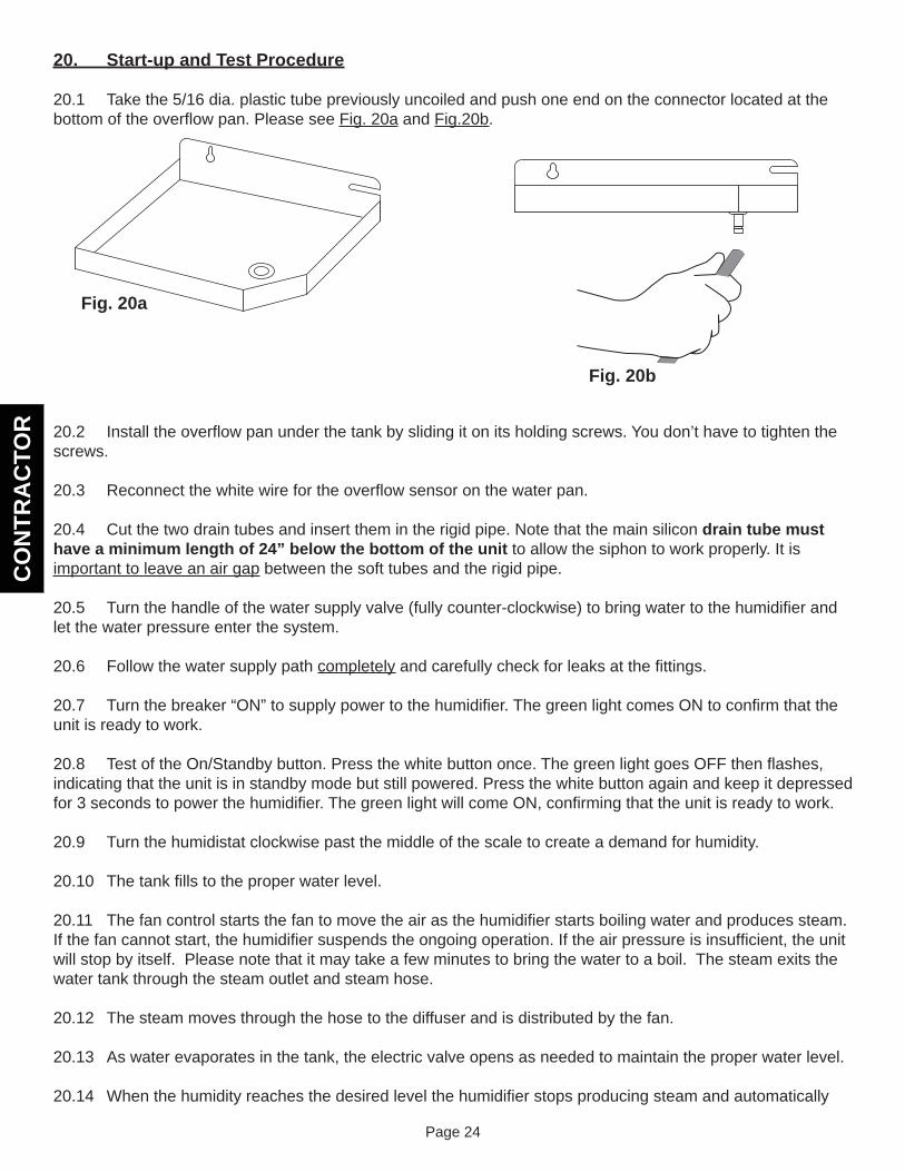
20.1 Take the 5/16 dia. plastic tube previously uncoiled and push one end on the connector located at the bottom of the overfl ow pan. Please see Fig. 20a and Fig.20b.
20.2 Install the overfl ow pan under the tank by sliding it on its holding screws. You don’t have to tighten the screws.
20.3 Reconnect the white wire for the overfl ow sensor on the water pan.
20.4 Cut the two drain tubes and insert them in the rigid pipe. Note that the main silicon drain tube must have a minimum length of 24” below the bottom of the unit to allow the siphon to work properly. It is important to leave an air gap between the soft tubes and the rigid pipe.
20.5 Turn the handle of the water supply valve (fully counter-clockwise) to bring water to the humidifi er and let the water pressure enter the system.
20.6 Follow the water supply path completely and carefully check for leaks at the fi ttings.
20.7 Turn the breaker “ON” to supply power to the humidifi er. The green light comes ON to confi rm that the unit is ready to work.
20.8 Test of the On/Standby button. Press the white button once. The green light goes OFF then fl ashes, indicating that the unit is in standby mode but still powered. Press the white button again and keep it depressed for 3 seconds to power the humidifi er. The green light will come ON, confi rming that the unit is ready to work.
20.9 Turn the humidistat clockwise past the middle of the scale to create a demand for humidity.
20.10 The tank fi lls to the proper water level.
20.11 The fan control starts the fan to move the air as the humidifi er starts boiling water and produces steam. If the fan cannot start, the humidifi er suspends the ongoing operation. If the air pressure is insuffi cient, the unit will stop by itself. Please note that it may take a few minutes to bring the water to a boil. The steam exits the water tank through the steam outlet and steam hose.
20.12 The steam moves through the hose to the diffuser and is distributed by the fan.
20.13 As water evaporates in the tank, the electric valve opens as needed to maintain the proper water level.
20.14 When the humidity reaches the desired level the humidifi er stops producing steam and automatically
Fig. 20a
Fig. 20b
CO
NTR
AC
TOR
Page 25
drains. In order to eliminate the residues and keep the tank as clean as possible, the humidifi er also drains after a certain number of boiling – refi ll cycles. If there is still a demand from the humidistat after draining, the tank refi lls and starts to produce steam again.
20.15 When the humidistat is satisfi ed, the fan continues to run for a short period of time in order to eliminate the steam from the ducts.
20.16 When everything is working fi ne, put the cover on the unit and attach it by turning the 1/4 turn latch to the right.
20.17 Please don’t forget to leave this instruction manual with the customer.
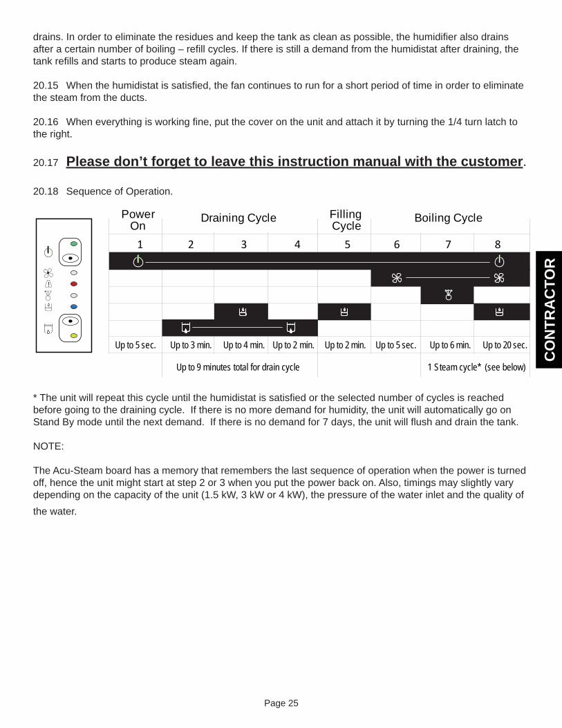
20.18 Sequence of Operation.
* The unit will repeat this cycle until the humidistat is satisfi ed or the selected number of cycles is reached before going to the draining cycle. If there is no more demand for humidity, the unit will automatically go on Stand By mode until the next demand. If there is no demand for 7 days, the unit will fl ush and drain the tank.
NOTE:
The Acu-Steam board has a memory that remembers the last sequence of operation when the power is turned off, hence the unit might start at step 2 or 3 when you put the power back on. Also, timings may slightly vary depending on the capacity of the unit (1.5 kW, 3 kW or 4 kW), the pressure of the water inlet and the quality of the water.
PowerOn
FillingCycle
1 2 3 4 5 6 7 8
Draining Cycle Boiling Cycle
Up to 5 sec. Up to 3 min. Up to 4 min.
Up to 9 minutes total for drain cycle 1 Steam cycle* (see below)
Up to 2 min. Up to 2 min. Up to 5 sec. Up to 6 min. Up to 20 sec.
!

CO
NTR
AC
TOR
Page 26
CO
NTR
AC
TOR
Page 27
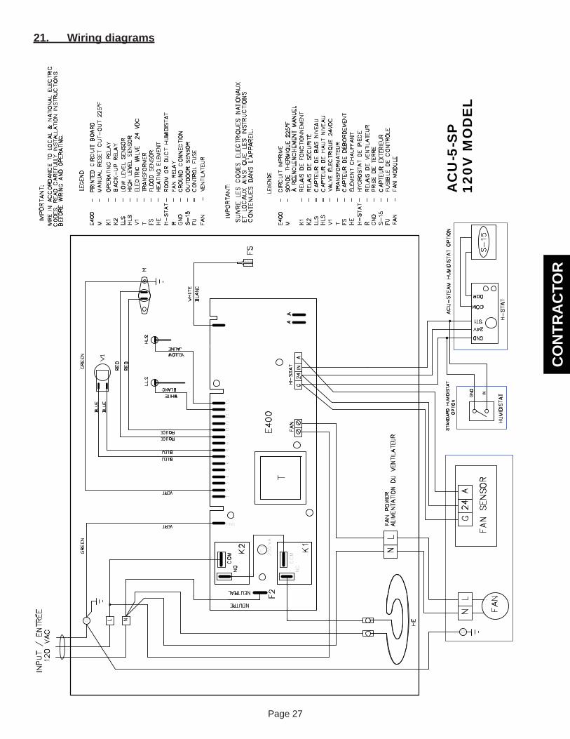
21. Wiring diagrams
T
COM
COM
E400
K2
K1
NO
NO
F2
HE
S-15
WIRE IN ACCORDANCE TO LOCAL & NATIONAL ELECTRIC
CODES. READ CAREFULLY INSTALLATION INSTRUCTIONS
BEFORE WIRING AND OPERATING.
OUTDOOR SENSOR
GROUND CONNECTION
FAN RELAY
ROOM OR DUCT HUMIDISTAT
HEATING ELEMENT
FLOOD SENSOR
TRANSFORMER
ELECTRIC VALVE 24 VDC
HIGH LEVEL SENSOR
LOW LEVEL SENSOR
MANUAL RESET CUT-OUT 225ºF
BACK-UP RELAY
OPERATING RELAY
PRINTED CIRCUIT BOARD
CIRCUIT IMPRIME
H-STAT
S-15
GND
RHE
-CAPTEUR EXTÉRIEUR
- - -
HYGROSTAT DE PIÈCE
RELAIS DE VENTILATEUR
PRISE DE TERRE
-ÉLÉMENT CHAUFFANT
MSONDE THERMIQUE 225ºF
LLS
V1
HLS
T FS
K2
K1
CAPTEUR DE BAS NIVEAU
-- - -
CAPTEUR DE HAUT NIVEAU
CAPTEUR DE DÉBORDEMENT
VALVE ÉLECTRIQUE 24VDC
TRANSFORMATEUR
---
RELAIS DE SÉCURITÉ
RELAIS DE FONCTIONNEMENT
-
IMPORTANT:
E400
LEGENDE
-
HE
H-STAT
S-15
R GND
- - - --
HLS
FS
V1
TK1
K2
LLS
- ------
IMPORTANT:
E400
M
LEGEND
--
À RÉENCLENCHEMENT MANUEL
FS
SUIVRE LES CODES ELECTRIQUES NATIONAUX
CONTENUES DANS L'APPAREIL.
ET LOCAUX AINSI QUE LES INSTRUCTIONS
250mA
FU
120V
MO
DE
L
CONTROL FUSE
-FU
FU
-FUSIBLE DE CONTRÔLE
FAN
-FAN MODULE
VENTILATEUR
FAN
-
AC
U-5
-SP
INPUT / ENTRÉE
G
IN24
G
FAN
12
34
56
78
910
1112
131415
H-STAT
WHITE
YELLOW
ROUGE
ROUGE
BLEU
BLEU
L N
NEUTRAL
GND
24V
ST1
COM
ODR
H-STAT
GND
VERT
VERT
AA
120 VAC
BLANC
JAUNE
NEUTRE
ACU-STEAM HUMIDISTAT OPTION
GND
IN
HUMIDISTAT
STANDARD HUMIDISTAT
OPTION
A
NL
NL
FAN
GG
24A
FAN SENSOR
FAN POWER
ALIMENTATION DU VENTILATEUR
V1
MHLS
LLS
WHIT
E
BLUE
BLUE
GREEN
GREEN
RED
RED
BLANC

CO
NTR
AC
TOR
Page 28
CO
NTR
AC
TOR
Page 29
Num
ber o
f fl a
shes
of t
he
re
d lig
htEr
ror D
escr
iptio
nH
umid
ifi er
Sta
tus
Act
ions
to b
e Ta
ken
by
the
Tech
nici
anR
eset
OFF
No
erro
rTh
e hu
mid
ifi er
is w
orki
ng fi
neN
one
Cou
ntin
uous
O
NTh
e fl o
od s
enso
r und
er th
e ta
nk
sens
es w
ater
in th
e pa
n.
Hum
idifi
er im
med
iate
ly s
uspe
nds
the
ongo
ing
oper
atio
n. H
eatin
g el
emen
ts
and
supp
ly v
alve
are
sw
itche
d of
f.
Turn
the
mai
n po
wer
OFF
, the
n -
Che
ck th
e dr
ain
tube
- C
heck
for a
bnor
mal
leak
s
Aut
omat
ic R
eset
whe
n sw
itchi
ng m
ain
pow
er
ON
1Th
e tw
o w
ater
leve
l sen
sors
are
m
isw
ired
or d
o no
t rea
d th
e w
ater
le
vel p
rope
rly.
Hum
idifi
er a
ttem
pts
to o
pera
te, t
hen
stop
s be
caus
e of
wro
ng in
form
atio
n fro
m w
ater
leve
l sen
sors
.
Turn
the
mai
n po
wer
OFF
, the
n -
Che
ck th
at th
e w
ater
leve
l se
nsor
s ar
e in
the
right
ord
er -
Cle
an th
e se
nsor
s
A
utom
atic
Res
et w
hen
switc
hing
mai
n po
wer
O
N
2Th
is c
ode
is n
ot u
sed
on th
is
mod
el -
Res
erve
d fo
r fut
ure
use
3In
adeq
uate
wat
er s
uppl
y. T
he
supp
ly v
alve
was
ope
n fo
r mor
e th
an 4
min
utes
.
Hum
idifi
er im
med
iate
ly s
uspe
nds
the
ongo
ing
oper
atio
n. H
eatin
g el
emen
ts
and
supp
ly v
alve
are
sw
itche
d of
f.
Turn
the
mai
n po
wer
OFF
, the
n ch
eck
the
wat
er s
uppl
y ci
rcui
t
Aut
omat
ic R
eset
whe
n sw
itchi
ng m
ain
pow
er
ON
4In
adeq
uate
dra
inag
e. T
he ta
nk
did
not d
rain
or t
he d
rain
ing
cycl
e is
too
long
.
Hum
idifi
er im
med
iate
ly s
uspe
nds
the
ongo
ing
oper
atio
n. H
eatin
g el
emen
ts
and
supp
ly v
alve
are
sw
itche
d of
f.
Turn
the
mai
n po
wer
OFF
, the
n ch
eck
the
drai
n tu
be
Aut
omat
ic R
eset
whe
n sw
itchi
ng m
ain
pow
er
ON
5Th
e fa
n is
not
runn
ing.
Hum
idifi
er im
med
iate
ly s
uspe
nds
the
ongo
ing
oper
atio
n. T
he u
nit g
oes
back
to n
orm
al o
pera
tion
as s
oon
as
the
erro
r con
ditio
n di
sapp
ears
.
Che
ck th
e w
iring
bet
wee
n th
e fa
n m
odul
e an
d st
eam
gen
erat
or.
Aut
omat
ic R
eset
w
hen
erro
r con
ditio
ns
disa
ppea
r
6Te
mpe
ratu
re in
side
the
tank
ex
ceed
ed th
e hi
gh te
mpe
ratu
re
cut-o
ut s
ettin
g.
The
high
tem
pera
ture
cut
-out
has
tri
pped
. The
hum
idifi
er im
med
iate
ly
susp
ends
the
ongo
ing
oper
atio
n.
Hea
ting
elem
ents
and
sup
ply
valv
e ar
e sw
itche
d of
f.
Turn
the
mai
n po
wer
OFF
, the
n -
Che
ck th
e st
eam
hos
e fo
r kin
ks
or b
lock
age
- Th
is is
a v
ery
serio
us c
ondi
tion
Afte
r pus
hing
on
the
ther
mal
cut
-out
but
ton,
au
tom
atic
rese
t whe
n sw
itchi
ng m
ain
pow
er
ON
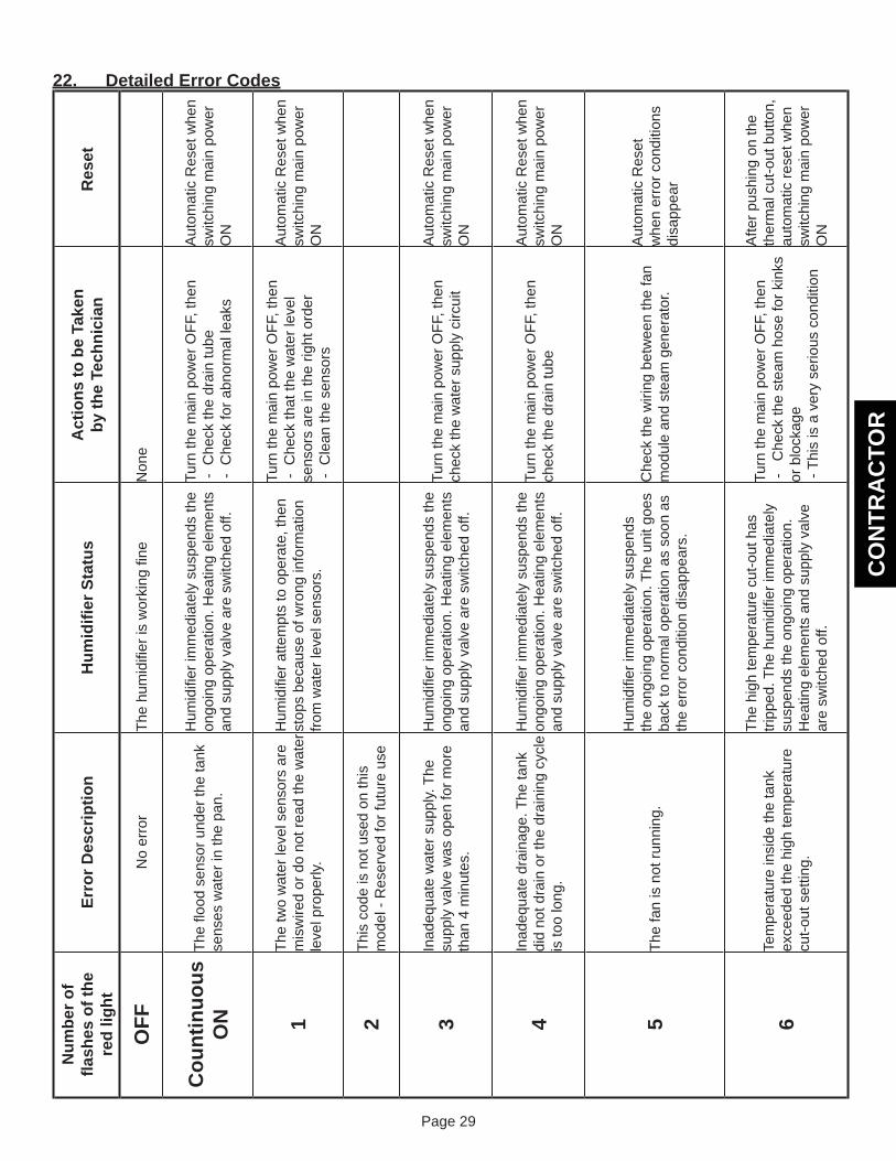
22. Detailed Error Codes


![[ARTICLE] 1 Real... · Web view(1) “Abandoned property” means mortgaged property with respect to which the homeowner and all persons claiming through the homeowner, including](https://img.dokumen.tips/doc/110x75/5a72d5a07f8b9abb538e09d3/article-1-real-doc-file-web-view1-abandoned-property-means.jpg)