Embed Size (px)
Citation preview
®
®
DAYTONSUPERIOR.COMCopyright © 2013 Dayton Superior Corporation, All Rights Reserved
APP
LIC
ATI
ON
GU
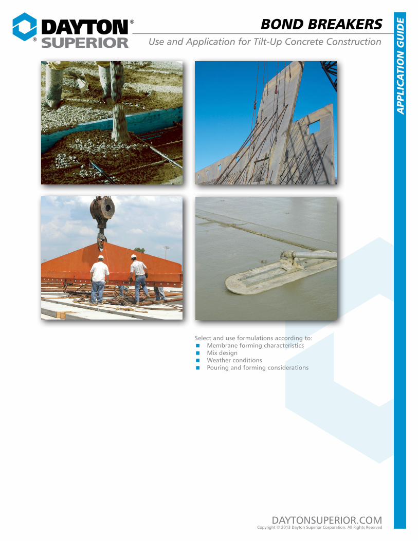
IDEBOND BREAKERS
Use and Application for Tilt-Up Concrete Construction
Select and use formulations according to:�� Membrane forming characteristics�� Mix design�� Weather conditions�� Pouring and forming considerations
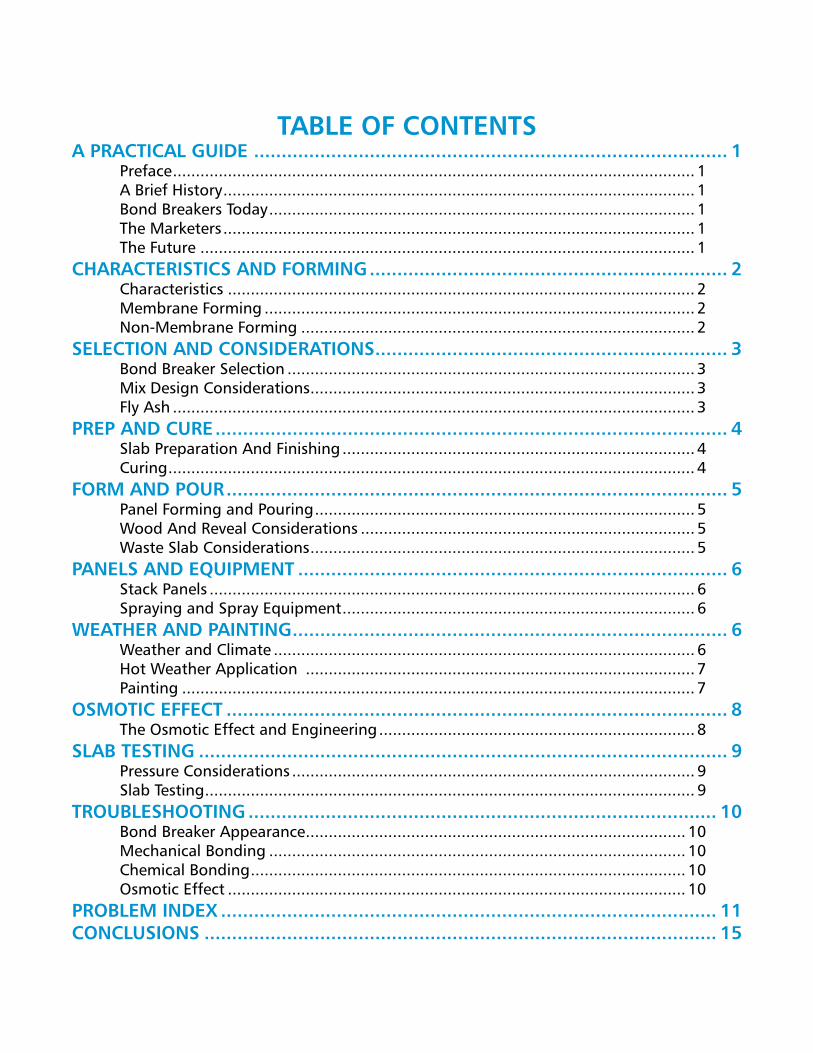
Table of ConTenTsa PRaCTICal GUIDe ...................................................................................... 1
Preface .................................................................................................................. 1A Brief History ....................................................................................................... 1Bond Breakers Today ............................................................................................. 1The Marketers ....................................................................................................... 1The Future ............................................................................................................ 1
CHaRaCTeRIsTICs anD foRMInG ................................................................. 2Characteristics ...................................................................................................... 2Membrane Forming .............................................................................................. 2Non-Membrane Forming ...................................................................................... 2
seleCTIon anD ConsIDeRaTIons ................................................................ 3Bond Breaker Selection ......................................................................................... 3Mix Design Considerations .................................................................................... 3Fly Ash .................................................................................................................. 3
PReP anD CURe ............................................................................................. 4Slab Preparation And Finishing ............................................................................. 4Curing ................................................................................................................... 4
foRM anD PoUR ........................................................................................... 5Panel Forming and Pouring ................................................................................... 5Wood And Reveal Considerations ......................................................................... 5Waste Slab Considerations .................................................................................... 5
Panels anD eQUIPMenT .............................................................................. 6Stack Panels .......................................................................................................... 6Spraying and Spray Equipment ............................................................................. 6
WeaTHeR anD PaInTInG ............................................................................... 6Weather and Climate ............................................................................................ 6Hot Weather Application ..................................................................................... 7Painting ................................................................................................................ 7
osMoTIC effeCT ........................................................................................... 8The Osmotic Effect and Engineering ..................................................................... 8
slab TesTInG ................................................................................................ 9Pressure Considerations ........................................................................................ 9Slab Testing ........................................................................................................... 9
TRoUblesHooTInG ..................................................................................... 10Bond Breaker Appearance ................................................................................... 10Mechanical Bonding ........................................................................................... 10Chemical Bonding ............................................................................................... 10Osmotic Effect .................................................................................................... 10
PRobleM InDeX .......................................................................................... 11ConClUsIons ............................................................................................. 15

®
®
Bond Breaker Application Guide
DAYTONSUPERIOR.COM 1 01/13
A PRACTICAL GUIDE PREfACEThe Tilt-Up Concrete Association (TCA) estimated that approximately 316,067,163 ft2 of tilt-wall panels (equaling to 790,167,908 ft2 of building using tilt-wall construction) was undertaken in 2007. This figure is probably a bit on the low side, as this survey was based on engineering data from the “Big Three” tilt-up hardware suppliers. It is known that several more independent tilt layout specialists also add to the square footage total. Tilt-up construction is growing, both nationally and internationally. Accompanying this growth is the use and application of bond breakers. Perhaps no chemical product is more poorly understood or misused as bond breakers. Hopefully, this booklet will help dispel some myths and shed needed light on the proper use of bond breaker products. The result can only be better production and less problems in the tilt-up construction process.
A BRIEf HIsToRyFollowing World War II, the need for manufacturing, warehouse, and office space in the United States pro-moted the use of efficient, fast-track building systems. Out of this need, arose the tilt-up method of concrete construction. The earliest methods of promoting sepa-ration of the tilt wall panel from the casting slab were greases or waxes applied to the casting slab. With the advent of plastics, plastic sheeting was used to provide curing for the slab and separation of the wall panel.
BonD BREAkERs ToDAyWith the arrival of chemically engineered materials and new polymers, manufacturers and formulators have introduced a number of commercially available bond breakers into the market. These materials have clear advantages over the crude waxes, greases, and poly-films of yesterday.
THE MARkETERsThose who manufacture and sell bond breakers includes Dayton Superior. There are several local blenders whose markets are limited to their immediate sphere of influ-ence. Dayton Superior is one of only a few manufac-turers who engineer and market tilt-up lifting/handling systems in addition to bond breakers.
THE fUTUREAs more advanced materials become available, it is anticipated that the formulations of bond breakers will also advance to even higher degrees of features and benefits.

®
®
Bond Breaker Application Guide
DAYTONSUPERIOR.COM 2 01/13
Figure 1
Figure 3
Figure 2
CHARACTERIsTICs AnD foRMInGCHARACTERIsTICsMost bond breakers fall into two major categories: Membrane forming and Non-Membrane forming. These can be further classified into water based and non-water based. Water based is as it suggests; the majority of the formulation is water. These materi-als usually meet the Volatile Organic Content (VOC) requirements of Federal, State, and Local regulations. The non-waterbased materials are typically based on some type of petroleum distillate, i.e. mineral spirits, aromatic oils, etc., and their use is restricted in more VOC stringent States.
MEMBRAnE foRMInGThese materials leave a water repellent surface mem-brane to seal the slab from the freshly poured wall panel (figure 1). As an additional consequence, they hold water in the freshly poured casting slab, and, thus are frequently used as curing membranes. In some cases, they are formulated to meet the requirements of American Standard Test Method (ASTM) C-309.
The majority of these are formulated with crude resins to form the thin film. Subsequent to application, the carrier evaporates leaving the resin membrane on the concrete surface. The resulting film is usually weakly bonded and will break down over time in the presence of UV light and heat.
non-MEMBRAnE foRMInGThe non-membrane forming bond breakers can be further categorized into reactive types and non-reactive types. Reactive bond breakers usually contain some type of fatty acid in the form of a stearate. The stearates react with the calcium hydroxide (lime) of the concrete to produce a crude soap (Fig. 2).
The stearate may react with any carbonated surface products present on the casting slab to also produce crude soap. In the non-reactive materials, a gelled waterproofing polymer is dispersed in the carrier. When these gels are applied to the casting slab, the gel plugs the micro surface capillaries of the slab, thus waterproofing it and making it resistant to the freshly poured wall panel (Fig. 3). Some formulations may include these inert waterproofing polymers and a reac-tive component as well.

®
®
Bond Breaker Application Guide
DAYTONSUPERIOR.COM 3 01/13
sELECTIon AnD ConsIDERATIonsBonD BREAkER sELECTIonCare must be taken in choosing a bond breaker. First, is the manufacturer reputable? Will the manufacturer stand behind the product with technical support and a product warranty? Do the product’s have a solid track record? Second, are there VOC requirements that must be met? This criteria alone may limit the choices. Third, are there subsequent panel or slab treatments that need to be addressed.
Do the slab specifications require a membrane forming curing compound or sealer meeting the requirements of ASTM C-309 or other specification? These materials should be applied first after slab finishing operations.
What are the prevalent climatic conditions? Moist, cool climates make proper slab curing less critical than hot, dry and windy conditions. A premium bond breaker, like those manufactured by Dayton Superior, may be chosen as a curing aid and bond breaker.
MIx DEsIGn ConsIDERATIonsThe majority of tilt-up construction falls into the in-dustrial/ commercial American Concrete Institute (ACI) class 4 or light-duty industrial ACI class 5. The concern here is with the quality of the finished slab, especially the top 1∕16" or 1∕8" of concrete. Not only will this have a direct bearing on the ultimate wearability of the slab, but on the performance of the bond breaker as well. These floors should not be poured with greater than a 5" slump.
Additionally, the minimum cement content should be 5½ sacks-depending on aggregate size. The smaller the gradation of aggregate, the greater the need for cement. These mixes, if properly prepared, will result in a compressive yield of at least 4000 psi, a tight hard finish, and greatly reduce the cracking, shrinkage, and low tensile strength associated with high water cement ratio mix designs. A good rule of thumb is not to exceed a .5 w/c. Proper preparation of the aggregate is also a consideration. Dry aggregates that absorb mix water can affect the outcome of the concrete. Conversely, surface wet aggregates can also affect the concrete outcome and durability by increasing the water ce-ment ratio.
fLy AsHMuch discussion about fly ash and its affect on the absorption, wearability, affect on water demand, etc. is currently underway. Studies by the Portland Cement Association, and ACI, et al, show that Class C fly ash concrete mixes show little difference from 100% ce-ment in ultimate compressive strength, although the strength curve is slower than with 100% cement. Also, these mixes exhibit water absorption rates, when cured, similar to 100% cement. Class F fly ash, on the other hand, reacts with the hydrated and unhydrated lime in cement, exhibits a greater need for moist curing, can show an early age increase in absorption, and a slower gain in compressive strength. The conclusion here is, when applying bond breaker to slabs containing fly ash, care must be taken for proper curing. Addition-ally, more bond breaker may be required to get the desired parting affect. Fly ash is not preferred by most successful tilt contractors. They reason that greater strength and slab densities are achieved via higher ce-ment content.
®
®
Bond Breaker Application Guide
DAYTONSUPERIOR.COM 4 01/13
Figure 4
Figure 5
Figure 6
PREP AnD CUREsLAB PREPARATIon AnD fInIsHInGA vibratory screed or a roller screed riding on the panel edges is recommended to bring the casting slab to it’s initial height. Bullfloating or straightedging should commence immediately after strikeoff to clean up any surface irregularities. As soon as the bleed water has dissipated, and the slab can support the weight of a worker, the slab should be power floated. Any finishing operation performed while there is excess moisture or bleed water on the surface can cause surface defects like scaling.
After power floating, and when any water sheen has disappeared, the slab should then be power troweled. Progressively increasing the tilt of the blades will result in a hard “burned” surface (Fig. 4). Proper slab prepa-ration is critical to the quality of tilt-up construction in general, and more significantly to the performance of the bond breaker. Poorly finished slabs greatly increase the chances of sticking by mechanical bonding of the wall panel to the casting slab.
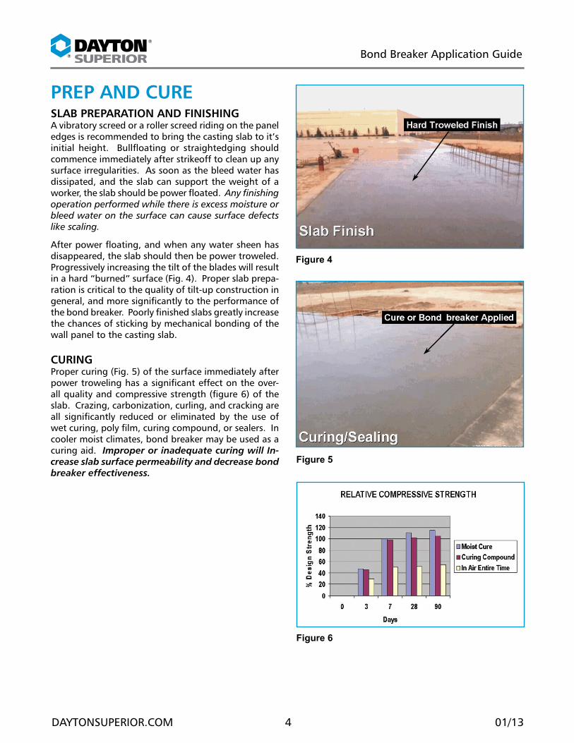
CURInGProper curing (Fig. 5) of the surface immediately after power troweling has a significant effect on the over-all quality and compressive strength (figure 6) of the slab. Crazing, carbonization, curling, and cracking are all significantly reduced or eliminated by the use of wet curing, poly film, curing compound, or sealers. In cooler moist climates, bond breaker may be used as a curing aid. Improper or inadequate curing will In-crease slab surface permeability and decrease bond breaker effectiveness.
®
®
Bond Breaker Application Guide
DAYTONSUPERIOR.COM 5 01/13
Figure 8
Figure 9
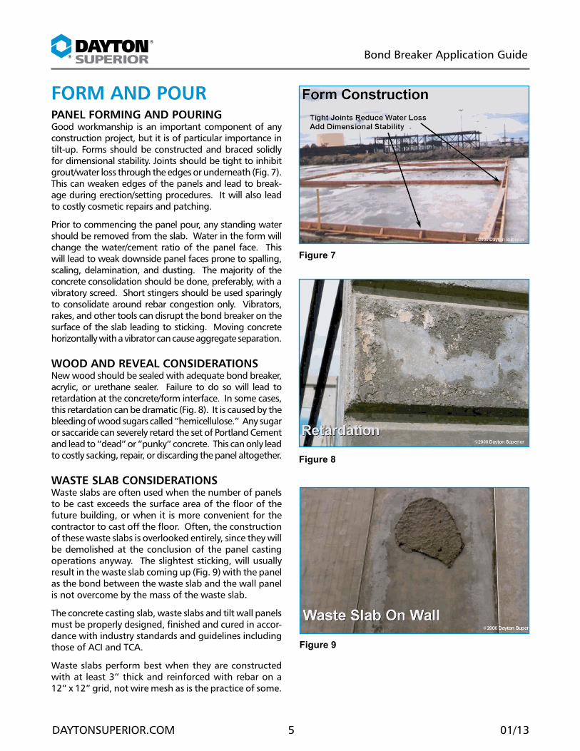
foRM AnD PoURPAnEL foRMInG AnD PoURInGGood workmanship is an important component of any construction project, but it is of particular importance in tilt-up. Forms should be constructed and braced solidly for dimensional stability. Joints should be tight to inhibit grout/water loss through the edges or underneath (Fig. 7). This can weaken edges of the panels and lead to break-age during erection/setting procedures. It will also lead to costly cosmetic repairs and patching.
Prior to commencing the panel pour, any standing water should be removed from the slab. Water in the form will change the water/cement ratio of the panel face. This will lead to weak downside panel faces prone to spalling, scaling, delamination, and dusting. The majority of the concrete consolidation should be done, preferably, with a vibratory screed. Short stingers should be used sparingly to consolidate around rebar congestion only. Vibrators, rakes, and other tools can disrupt the bond breaker on the surface of the slab leading to sticking. Moving concrete horizontally with a vibrator can cause aggregate separation.
WooD AnD REvEAL ConsIDERATIonsNew wood should be sealed with adequate bond breaker, acrylic, or urethane sealer. Failure to do so will lead to retardation at the concrete/form interface. In some cases, this retardation can be dramatic (Fig. 8). It is caused by the bleeding of wood sugars called “hemicellulose.” Any sugar or saccaride can severely retard the set of Portland Cement and lead to “dead” or “punky” concrete. This can only lead to costly sacking, repair, or discarding the panel altogether.
WAsTE sLAB ConsIDERATIonsWaste slabs are often used when the number of panels to be cast exceeds the surface area of the floor of the future building, or when it is more convenient for the contractor to cast off the floor. Often, the construction of these waste slabs is overlooked entirely, since they will be demolished at the conclusion of the panel casting operations anyway. The slightest sticking, will usually result in the waste slab coming up (Fig. 9) with the panel as the bond between the waste slab and the wall panel is not overcome by the mass of the waste slab.
The concrete casting slab, waste slabs and tilt wall panels must be properly designed, finished and cured in accor-dance with industry standards and guidelines including those of ACI and TCA.
Waste slabs perform best when they are constructed with at least 3” thick and reinforced with rebar on a 12” x 12” grid, not wire mesh as is the practice of some.
Figure 7
®
®
Bond Breaker Application Guide
DAYTONSUPERIOR.COM 6 01/13
Figure 11
Figure 10
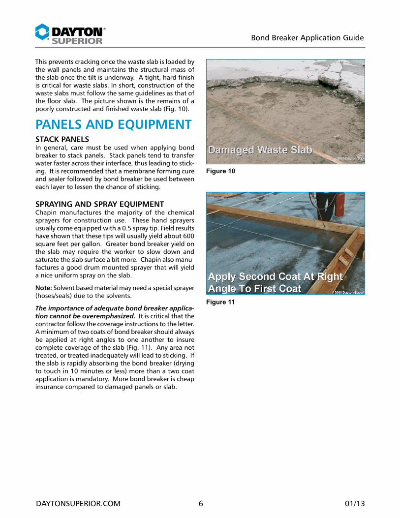
This prevents cracking once the waste slab is loaded by the wall panels and maintains the structural mass of the slab once the tilt is underway. A tight, hard finish is critical for waste slabs. In short, construction of the waste slabs must follow the same guidelines as that of the floor slab. The picture shown is the remains of a poorly constructed and finished waste slab (Fig. 10).
PAnELs AnD EQUIPMEnTsTACk PAnELsIn general, care must be used when applying bond breaker to stack panels. Stack panels tend to transfer water faster across their interface, thus leading to stick-ing. It is recommended that a membrane forming cure and sealer followed by bond breaker be used between each layer to lessen the chance of sticking.
sPRAyInG AnD sPRAy EQUIPMEnTChapin manufactures the majority of the chemical sprayers for construction use. These hand sprayers usually come equipped with a 0.5 spray tip. Field results have shown that these tips will usually yield about 600 square feet per gallon. Greater bond breaker yield on the slab may require the worker to slow down and saturate the slab surface a bit more. Chapin also manu-factures a good drum mounted sprayer that will yield a nice uniform spray on the slab.
note: Solvent based material may need a special sprayer (hoses/seals) due to the solvents.
The importance of adequate bond breaker applica-tion cannot be overemphasized. It is critical that the contractor follow the coverage instructions to the letter. A minimum of two coats of bond breaker should always be applied at right angles to one another to insure complete coverage of the slab (Fig. 11). Any area not treated, or treated inadequately will lead to sticking. If the slab is rapidly absorbing the bond breaker (drying to touch in 10 minutes or less) more than a two coat application is mandatory. More bond breaker is cheap insurance compared to damaged panels or slab.
®
®
Bond Breaker Application Guide
DAYTONSUPERIOR.COM 7 01/13
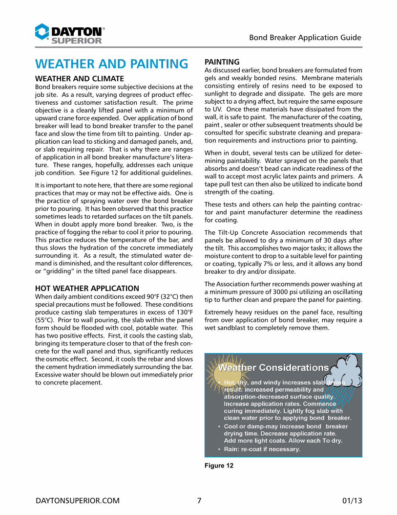
WEATHER AnD PAInTInGWEATHER AnD CLIMATEBond breakers require some subjective decisions at the job site. As a result, varying degrees of product effec-tiveness and customer satisfaction result. The prime objective is a cleanly lifted panel with a minimum of upward crane force expended. Over application of bond breaker will lead to bond breaker transfer to the panel face and slow the time from tilt to painting. Under ap-plication can lead to sticking and damaged panels, and, or slab requiring repair. That is why there are ranges of application in all bond breaker manufacture’s litera-ture. These ranges, hopefully, addresses each unique job condition. See Figure 12 for additional guidelines.
It is important to note here, that there are some regional practices that may or may not be effective aids. One is the practice of spraying water over the bond breaker prior to pouring. It has been observed that this practice sometimes leads to retarded surfaces on the tilt panels. When in doubt apply more bond breaker. Two, is the practice of fogging the rebar to cool it prior to pouring. This practice reduces the temperature of the bar, and thus slows the hydration of the concrete immediately surrounding it. As a result, the stimulated water de-mand is diminished, and the resultant color differences, or “gridding” in the tilted panel face disappears.
HoT WEATHER APPLICATIon When daily ambient conditions exceed 90°F (32°C) then special precautions must be followed. These conditions produce casting slab temperatures in excess of 130°F (55°C). Prior to wall pouring, the slab within the panel form should be flooded with cool, potable water. This has two positive effects. First, it cools the casting slab, bringing its temperature closer to that of the fresh con-crete for the wall panel and thus, significantly reduces the osmotic effect. Second, it cools the rebar and slows the cement hydration immediately surrounding the bar. Excessive water should be blown out immediately prior to concrete placement.
PAInTInGAs discussed earlier, bond breakers are formulated from gels and weakly bonded resins. Membrane materials consisting entirely of resins need to be exposed to sunlight to degrade and dissipate. The gels are more subject to a drying affect, but require the same exposure to UV. Once these materials have dissipated from the wall, it is safe to paint. The manufacturer of the coating, paint , sealer or other subsequent treatments should be consulted for specific substrate cleaning and prepara-tion requirements and instructions prior to painting.
When in doubt, several tests can be utilized for deter-mining paintability. Water sprayed on the panels that absorbs and doesn’t bead can indicate readiness of the wall to accept most acrylic latex paints and primers. A tape pull test can then also be utilized to indicate bond strength of the coating.
These tests and others can help the painting contrac-tor and paint manufacturer determine the readiness for coating.
The Tilt-Up Concrete Association recommends that panels be allowed to dry a minimum of 30 days after the tilt. This accomplishes two major tasks; it allows the moisture content to drop to a suitable level for painting or coating, typically 7% or less, and it allows any bond breaker to dry and/or dissipate.
The Association further recommends power washing at a minimum pressure of 3000 psi utilizing an oscillating tip to further clean and prepare the panel for painting.
Extremely heavy residues on the panel face, resulting from over application of bond breaker, may require a wet sandblast to completely remove them.
Figure 12
®
®
Bond Breaker Application Guide
DAYTONSUPERIOR.COM 8 01/13
Figure 13
Figure 14
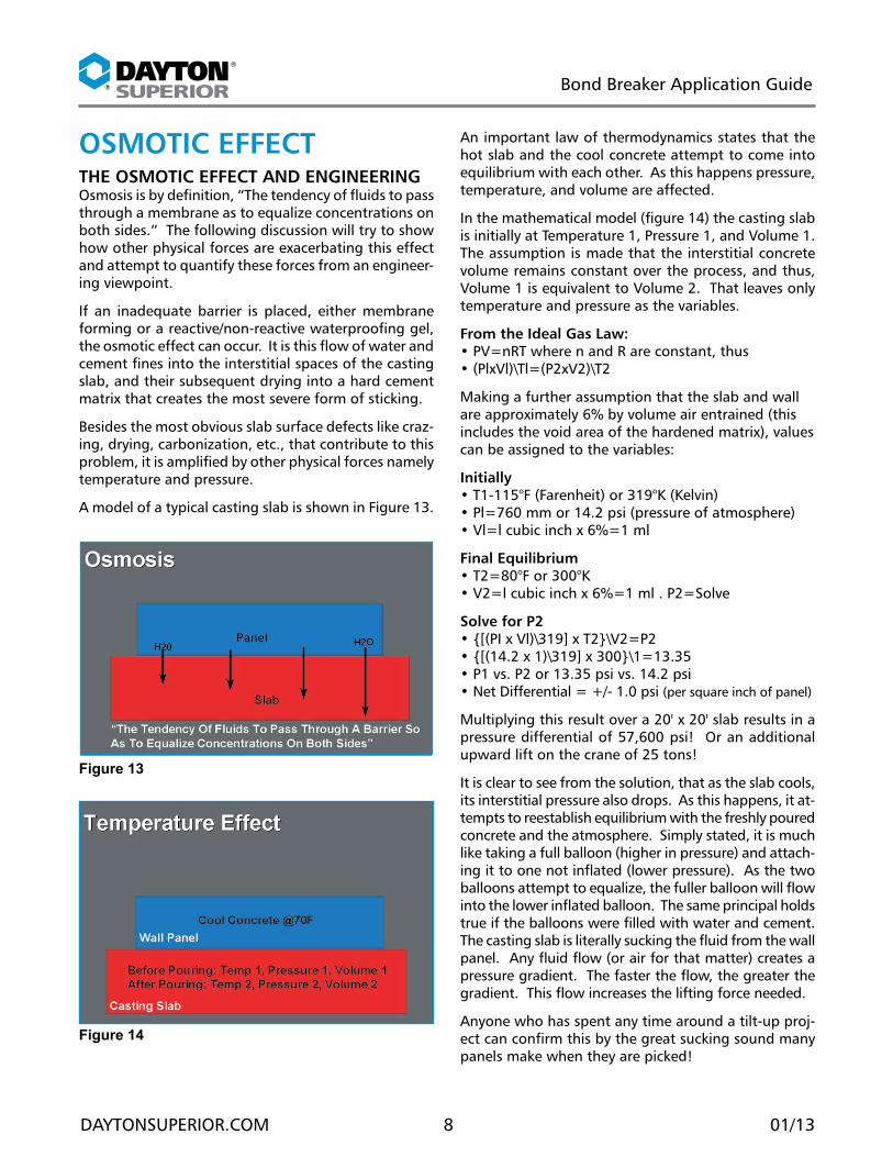
osMoTIC EffECTTHE osMoTIC EffECT AnD EnGInEERInGOsmosis is by definition, “The tendency of fluids to pass through a membrane as to equalize concentrations on both sides.” The following discussion will try to show how other physical forces are exacerbating this effect and attempt to quantify these forces from an engineer-ing viewpoint.
If an inadequate barrier is placed, either membrane forming or a reactive/non-reactive waterproofing gel, the osmotic effect can occur. It is this flow of water and cement fines into the interstitial spaces of the casting slab, and their subsequent drying into a hard cement matrix that creates the most severe form of sticking.
Besides the most obvious slab surface defects like craz-ing, drying, carbonization, etc., that contribute to this problem, it is amplified by other physical forces namely temperature and pressure.
A model of a typical casting slab is shown in Figure 13.
An important law of thermodynamics states that the hot slab and the cool concrete attempt to come into equilibrium with each other. As this happens pressure, temperature, and volume are affected.
In the mathematical model (figure 14) the casting slab is initially at Temperature 1, Pressure 1, and Volume 1. The assumption is made that the interstitial concrete volume remains constant over the process, and thus, Volume 1 is equivalent to Volume 2. That leaves only temperature and pressure as the variables.
from the Ideal Gas Law: • PV=nRT where n and R are constant, thus • (PlxVl)\Tl=(P2xV2)\T2
Making a further assumption that the slab and wall are approximately 6% by volume air entrained (this includes the void area of the hardened matrix), values can be assigned to the variables:
Initially • T1-115°F (Farenheit) or 319°K (Kelvin) • Pl=760 mm or 14.2 psi (pressure of atmosphere) • Vl=l cubic inch x 6%=1 ml
final Equilibrium • T2=80°F or 300°K • V2=l cubic inch x 6%=1 ml . P2=Solve
Solve for P2 • {[(PI x Vl)\319] x T2}\V2=P2 • {[(14.2 x 1)\319] x 300}\1=13.35 • P1 vs. P2 or 13.35 psi vs. 14.2 psi • Net Differential = +/- 1.0 psi (per square inch of panel)
Multiplying this result over a 20' x 20' slab results in a pressure differential of 57,600 psi! Or an additional upward lift on the crane of 25 tons!
It is clear to see from the solution, that as the slab cools, its interstitial pressure also drops. As this happens, it at-tempts to reestablish equilibrium with the freshly poured concrete and the atmosphere. Simply stated, it is much like taking a full balloon (higher in pressure) and attach-ing it to one not inflated (lower pressure). As the two balloons attempt to equalize, the fuller balloon will flow into the lower inflated balloon. The same principal holds true if the balloons were filled with water and cement. The casting slab is literally sucking the fluid from the wall panel. Any fluid flow (or air for that matter) creates a pressure gradient. The faster the flow, the greater the gradient. This flow increases the lifting force needed.
Anyone who has spent any time around a tilt-up proj-ect can confirm this by the great sucking sound many panels make when they are picked!

®
®
Bond Breaker Application Guide
DAYTONSUPERIOR.COM 9 01/13
Figure 15
Figure 16
sLAB TEsTInGPREssURE ConsIDERATIonsFigure 15 illustrates how thicker panels can and will exert more hydrostatic head, when in the fluid and plastic state, on a slab. This increased pressure can potentially increase the risk of sticking as the fines and water are pushed under pressure into the casting slab. It can be safely said, that proper curing of the casting slab and adequate application of the bond breaker are even more critical with thicker panels.
As manufacturers of lift systems increase their lifting capacities, these larger, thicker panels are becoming more common.
sLAB TEsTInGSeveral methods have been developed to test for the proper application of bond breaker. The most common and easiest method is the “water bead” test. Several areas of the slab are sprinkled with water and observed. The water should bead into small drops or puddles with uniform rounded edges indicating maximum surface tension on the slab. A good rule of thumb is that the water beads should appear much like that of water on a freshly waxed car. The dry applied bond breaker should also have a soap like feel, and the surface should look like the bond breaker was uniformly applied.
Properly applied bond breaker will bead water as in Fig-ure 16. It will also “bead” the freshly poured concrete and prevent bonding and sticking. At the micro-level, cement paste and water are inhibited from penetrating down into the capillary structure of the casting slab. With reactive bond breakers, a slight retardation is occurring at the slab/panel interface further inhibiting the bond of the freshly poured panel and the casting slab. Although this method is the most widely used, it is still subjective. Another, more accurate, method has been developed by Richmond Chemical as a predictor of panel lifting ease and bond breaker application.

®
®
Bond Breaker Application Guide
DAYTONSUPERIOR.COM 10 01/13
Figure 17
Figure 18
osMoTIC EffECTIn this method, a rhylum column, available from most scientific glassware suppliers, is sealed with plumbers putty and attached to the slab. The column is filled with fresh water and the start time noted (Fig. 17).
Several hours should elapse before checking to see how much water has been absorbed into the slab. Proper ap-plication of bond breaker should allow no more than a 0 to .5 ml loss in a two hour time period (Fig. 18). Any greater absorption indicates the need for additional bond breaker.
When performing this test, several areas of the slab should be tested. Not only suspect areas, but areas reasonably ascertained to have received adequate bond breaker ap-plication. The results should be noted and compared.
TRoUBLEsHooTInGBonD BREAkER APPEARAnCE
APPEARAnCE CAUsE REMEDyBond breaker milky or opaque (solvent based only).
Poss ib le water contamination.
Tightly stopper drums. Store on sides. Cover to prevent water buildup.
Material seems thick.
Carrier is evaporat-ing.
Tightly seal drum. Store away from excessive heat. Shade from sun.
Lumps in bond breaker.
Carrier evaporat-ing. Material has sat too long. Out of date stock. Ma-terial was frozen.
Seal drum. Use stock not over 1 year old.
Bond breaker clear. Solids have settled. Mechanically agi-tate or mix. Thor-oughly mix before each use.
MECHAnICAL BonDInGThis can be the result of a poor surface finish. A tight, steel troweled finish is the most desirable slab finish. Broom finished, bull floated, or other non-bumished finishes create open peaks and valleys on the slab. The result is that of a construction joint-the wall becomes “keyed” to the casting slab.
Additionally, these peaks and valleys propagate more surface area for the bond breaker to cover, thus reduc-ing its overall coverage rate. In a sense, it would take far more bond breaker to cover Colorado than, say, Kansas.
CHEMICAL BonDInGIt is well known that wet concrete or mortar will stick to itself. The chief aim of bond breakers is to prevent this contact. In the case of membrane forming bond breakers, contact is prevented by a physical barrier between the panel and the casting slab. In the case of non-membrane bond breakers, bonding is prevented by the hydrophobic gel and/or retardation reaction. Disruption of either of these types of bond breakers by weather, workers, vibration, or other force will lead to chemical bonding.
osMoTIC EffECTEarlier it was demonstrated how the flow of fluid through a porous media such as concrete leads to pressure dif-ferentials and sucking. It was further demonstrated how temperature differences between the wall panel and slab can amplify this effect. Again, adequate application of bond breaker can stop this from happening.
On the following pages more problems and their pos-sible solutions will be illustrated.

®
®
Bond Breaker Application Guide
DAYTONSUPERIOR.COM 11 01/13
PRoBLEM InDExPRoBLEM: White spots on slab
CAUsE: Depending on the finishing techniques, materials used or contained in the concrete, most slabs will exhibit some degree of differential absorption. Porous concrete. High water/cement ratio. Bond breaker absorbed into slab. Oversaturated (small white spots) aggregate added to the mix.
soLUTIon: Apply additional bond breaker.
PRoBLEM: sticky Areas on slab
CAUsE: Many of the waterproofing gel, non-membrane type bond breakers contain substances not unlike petro-leum jelly. These materials never really dry, but harden. Properly dried bond breaker may feel or appear much like fly paper. This is normal and OK to pour on. Stickiness may also be caused by over-application of bond breaker, or, not enough time was allowed for drying between coats. Pos-sibly, it was rained on before drying was allowed.
soLUTIon: Spray several light coats. Avoid spraying prior to rain.
PRoBLEM: Cure Coat or sealer Transfers To Wall Panel (fig. 19)
CAUsE: Most cures or sealers have adhesive properties when sprayed over damp concrete. When they are sprayed over standing water about the best that can be expected is much like oil floating on water. This also may be caused by inadequate bond breaker over the top of the sealer coat.
soLUTIon: Wait until any bleed water brought to the sur-face by finishing is gone before applying cure or sealer. Ap-ply adequate bond breaker over sealer. Don’t spray solvent bond breaker on top of water based sealer. Water based bond breaker over solvent based sealer is ok.
PRoBLEM: Water Bead Test or Rhylum Column shows Uneven Absorption (Fig. 20)
CAUsE: This usually indicates areas either missed or under-sprayed during bond breaker application. The problem could be intensified by very porous areas of the slab.
soLUTIon: Re-spray those areas indicated by the tests.
PRoBLEM: scuff Marks Transferred To The Wall (fig. 21)
CAUsE: Heavy application of bond breaker. Slab walked on before bond breaker dry. Did not allow adequate drying time between coats.
soLUTIon: As with painting, several light coats are pre-ferred over one heavy coat. The old adage is, “If you don’t want it on the wall, don’t put it on the slab.”
Figure 19
Figure 20
Figure 21
®
®
Bond Breaker Application Guide
DAYTONSUPERIOR.COM 12 01/13
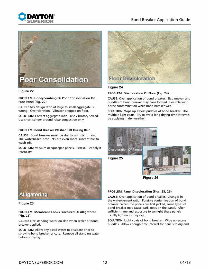
PRoBLEM: Discoloration of floor (fig. 24)
CAUsE: Over application of bond breaker. Slab uneven and puddles of bond breaker may have formed. P ossible wind borne contamination while bond breaker wet.
soLUTIon: Wipe up excess puddles of bond breaker. Use multiple light coats. Try to avoid long drying time intervals by applying in dry weather.
PRoBLEM: Panel Discoloration (figs. 25, 26)
CAUsE: Over-application of bond breaker. Changes in the water/cement ratio. Possible contamination of bond breaker. When the panels are first picked, some types of bond breaker may cause dark areas on the panel. After sufficient time and exposure to sunlight these panels usually lighten as they dry.
soLUTIon: Light coats of bond breaker. Wipe up excess puddles. Allow enough time interval for panels to dry and
PRoBLEM: Honeycombing or Poor Consolidation on face Panel (fig. 22)
CAUsE: Mix design ratio of large to small aggregate is wrong. Over vibration. Vibrator dragged on floor.
soLUTIon: Correct aggregate ratio. Use vibratory screed. Use short stinger around rebar congestion only.
PRoBLEM: Bond Breaker Washed off During Rain
CAUsE: Bond breaker must be dry to withstand rain. The waterbased products are even more susceptible to wash off.
soLUTIon: Vacuum or squeegee panels. Retest. Reapply if necessary.
PRoBLEM: Membrane Looks fractured or Alligatored (fig. 23)
CAUsE: Free standing water on slab when sealer or bond breaker applied.
soLUTIon: Allow any bleed water to dissipate prior to spraying bond breaker or cure. Remove all standing water before spraying.
Figure 23
Figure 22
Figure 26
Figure 25
Figure 24
®
®
Bond Breaker Application Guide
DAYTONSUPERIOR.COM 13 01/13
the membrane forming bond breakers to dissipate.
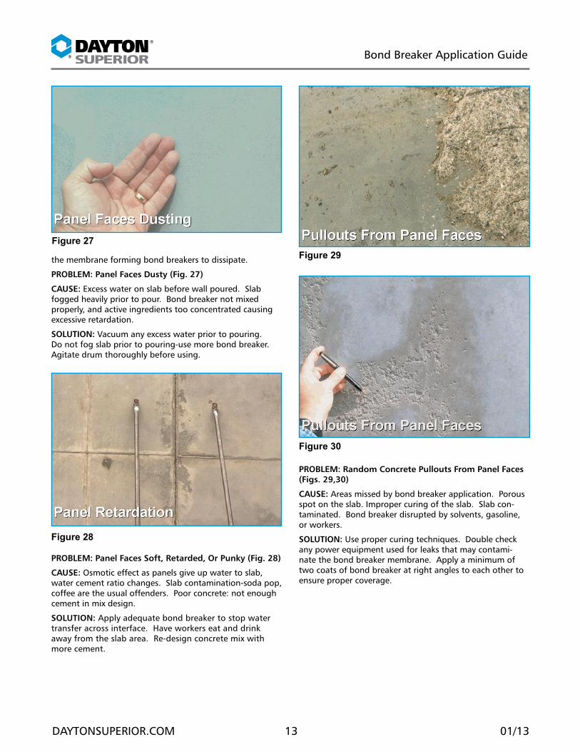
PRoBLEM: Panel faces Dusty (fig. 27)
CAUsE: Excess water on slab before wall poured. Slab fogged heavily prior to pour. Bond breaker not mixed properly, and active ingredients too concentrated causing excessive retardation.
soLUTIon: Vacuum any excess water prior to pouring. Do not fog slab prior to pouring-use more bond breaker. Agitate drum thoroughly before using.
PRoBLEM: Panel faces soft, Retarded, or Punky (fig. 28)
CAUsE: Osmotic effect as panels give up water to slab, water cement ratio changes. Slab contamination-soda pop, coffee are the usual offenders. Poor concrete: not enough cement in mix design.
soLUTIon: Apply adequate bond breaker to stop water transfer across interface. Have workers eat and drink away from the slab area. Re-design concrete mix with more cement.
PRoBLEM: Random Concrete Pullouts from Panel faces (figs. 29,30)
CAUsE: Areas missed by bond breaker application. Porous spot on the slab. Improper curing of the slab. Slab con-taminated. Bond breaker disrupted by solvents, gasoline, or workers.
soLUTIon: Use proper curing techniques. Double check any power equipment used for leaks that may contami-nate the bond breaker membrane. Apply a minimum of two coats of bond breaker at right angles to each other to ensure proper coverage.
Figure 27
Figure 28
Figure 29
Figure 30
®
®
Bond Breaker Application Guide
DAYTONSUPERIOR.COM 14 01/13
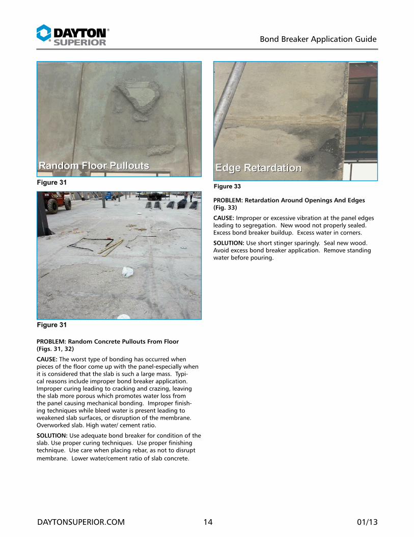
PRoBLEM: Random Concrete Pullouts from floor (figs. 31, 32)
CAUsE: The worst type of bonding has occurred when pieces of the floor come up with the panel-especially when it is considered that the slab is such a large mass. Typi-cal reasons include improper bond breaker application. Improper curing leading to cracking and crazing, leaving the slab more porous which promotes water loss from the panel causing mechanical bonding. Improper finish-ing techniques while bleed water is present leading to weakened slab surfaces, or disruption of the membrane. Overworked slab. High water/ cement ratio.
soLUTIon: Use adequate bond breaker for condition of the slab. Use proper curing techniques. Use proper finishing technique. Use care when placing rebar, as not to disrupt membrane. Lower water/cement ratio of slab concrete.
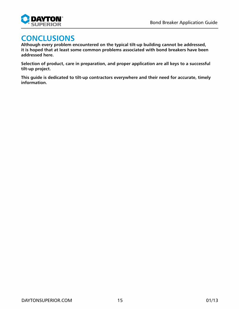
PRoBLEM: Retardation Around openings And Edges (fig. 33)
CAUsE: Improper or excessive vibration at the panel edges leading to segregation. New wood not properly sealed. Excess bond breaker buildup. Excess water in corners.
soLUTIon: Use short stinger sparingly. Seal new wood. Avoid excess bond breaker application. Remove standing water before pouring.
Figure 31
Figure 31
Figure 33
®
®
Bond Breaker Application Guide
DAYTONSUPERIOR.COM 15 01/13
ConCLUsIonsAlthough every problem encountered on the typical tilt-up building cannot be addressed, it is hoped that at least some common problems associated with bond breakers have been addressed here.
selection of product, care in preparation, and proper application are all keys to a successful tilt-up project.
This guide is dedicated to tilt-up contractors everywhere and their need for accurate, timely information.
®
®
Bond Breaker Application Guide
DAYTONSUPERIOR.COM 16 01/13
InDEx of fIGUREsFigure 1. Membrane Forming Bond Breaker . 2Figure 2. Reactive Bond Breaker ................ 2Figure 3. Non-Reactive Bond Breaker ........ 2Figure 4. Slab Finish .................................. 4Figure 5. Curing and Sealing ..................... 4Figure 7. Form Construction ...................... 5Figure 8. Wood Retardation ...................... 5Figure 9. Waste Slab On Wall .................... 5Figure 10. Destroyed Waste Slab ............... 6Figure 11. Spraying Bond Breaker ............. 6Figure 12. Weather Considerations ........... 7Figure 13. Osmosis .................................... 8Figure 14. Temperature Effect ................... 8Figure 15. Pressure Considerations ............ 9Figure 16. Water Bead Test ........................ 9Figure 17. Start Rhylum Test .................... 10Figure 18. End Rhylum Test ..................... 10Figure 19. Sealer Transfer ........................ 11Figure 20. Uneven Absorption ................. 11Figure 21. Scuff Marks ............................ 11Figure 22. Poor Consolidation ................. 12Figure 23. Alligatoring ............................ 12Figure 24. Floor Discoloration ................. 12Figure 25. Panel Discoloration ................. 12Figure 26. Excess Bond Breaker Buildup .. 12Figure 27. Dusting ................................... 13Figure 28. Panel Retardation ................... 13Figure 29. Panel Face Pullouts ................. 13Figure 30. Panel Face Pullouts ................. 13Figure 31. Floor Pullouts .......................... 14Figure 33. Edge Retardation .................... 14

W W W . D A Y T O N S U P E R I O R . C O M • B U I L D I N G S T R E N G T HCopyright © 2013 Dayton Superior Corporation, All Rights Reserved
®
®
CoRPoRaTe HeaDQUaRTeRs1125 Byers RoadMiamisburg, OH 45342937-866-0711
aCCessoRIes anD CHeMICalsCustomer Service: 888-977-9600Technical Assistance: [email protected]
foRMInG PRoDUCTsCustomer Service: 800-800-7966Technical Assistance: [email protected]
bRIDGe DeCK foRMInGAdjustable Joist HangersBridge Overhang BracketsHaunch and Fillet FormingPres-Steel, Coil Rod and Con-Beam
HangersScreed Supports
CHeMICalsBond BreakersCleaners / StrippersConcrete Repair/RestorationCuring Compounds / SealersEpoxiesFloor LevelersForm Release AgentsGroutHardeners / Industrial ToppingsLiquid DensifiersSurface Retarders
foRMInG anD sHoRInGAluminum ShoringGanged FormworkGarage Beam SystemHandset FormworkHighway FormsJump FormsModular Deck ShoringOne Sided FramesSelf Spanning FormsSteel Frame Shoring
foRMlIneRsABS Plastic Polystyrene Plastic
PaVInGDowel Bar Expansion CapsDowel Bar Retrofit SystemElastomeric and Hot Pour Joint SealMetal Keyway Form SystemsTie Bar AssembliesTransverse Bar AssembliesWelded Dowel AssembliesWire Baskets without Dowels
PReCasTAnchors and Lift SystemsCoil / Ferrule InsertsCore PlugsMagnetsPrecast FormsRustications/ChamfersSandwich Panel ConnectorShear Connectors Slotted Inserts
RebaR sPlICInGForged Dowel Bar CouplersLockshear Bolt CouplersShear Resistance ProductsStraight Thread CouplersTaper Thread Couplers
RebaR sUPPoRTsConcrete Dobies Continuous Plastic and Steel
Bar SupportsIndividual Plastic and Steel
Bar SupportsMesh ChairsPaving ChairsSide Form Spacers
TIes anD aCCessoRIesModular Form TiesSingle Waler SystemTies and Accessories
TIlT-UPBraces and Brace AnchorsHelical Ground AnchorsSetting PlugsStrongback SystemTilt-Up Anchors and Lifting Systems
ConCReTe aCCessoRIesAccubrace®
Aztec®
Bar Lock®
Corewall®
Fleet-Lift™Swift Lift®
Taper-Lock®
ConsTRUCTIon CHeMICalsUnitex®
foRMInG PRoDUCTsSymons®
Max-A-Form®
Steel-Ply®
Sym-Ply®
DayTon sUPeRIoR bRanDs
DayTon sUPeRIoR PRoDUCTs
ConTaCT InfoRMaTIon
DSC2701/13$9.95