Embed Size (px)
Citation preview

Tilt-Up Concrete Construction
to Prefabricated Concrete Elements
– the changes to AS3850
Jeff Stratford – Business Manager Precast & Tilt-Up ANZ
Reid Construction Systems
November 2015

Agenda
• The AS3850 journey
• Catalyst for updating the standard
• Major changes from 2003 to 2015
• Part 1: General Requirements
• Part 2: Building Construction
• High level summary by Stakeholder
• Alignment with the NCOP
• Questions

Agenda
• The AS3850 journey
• Catalyst for updating the standard
• Major changes from 2003 to 2015
• Part 1: General Requirements
• Part 2: Building Construction
• High level summary by Stakeholder
• Alignment with the NCOP
• Questions

The AS3850 journey
• Recent version was published in 2003
• Focused on ‘Tilt-Up Concrete Construction’
• Safety critical issues with 2003 version
• Review started in July 2009
• BD-066 committee was led by Paul Uno
• Wide ranging participation on the committee
• Involvement with Safe Work Australia (SWA)
• Alignment in scope and definition to NCOP
• Draft went to public comment twice
• Finally published 3 September 2015
Associations Involved :• Australasian Fire and Emergency Service
Authorities Council
• Australian Council of Trade Unions
• Australian Institute of Building Surveyors
• Australian Steel Institute
• Building Designers Association of NSW
• Cement Concrete and Aggregates Australia
• Concrete Institute of Australia
• Concrete Pipe Association of Australasia
• Crane Industry Council of Australia
• Engineers Australia
• Master Builders Australia
• NATA
• National Precast (NPCAA)
• Steel Reinforcement Institute of Australia
• Sydney University
• WorkCover New South Wales
• WorkSafe Victoria

Agenda
• The AS3850 journey
• Catalyst for updating the standard
• Major changes from 2003 to 2015
• Part 1: General Requirements
• Part 2: Building Construction
• High level summary by Stakeholder
• Alignment with the NCOP
• Questions

Catalyst for updating the standard
• 2003 version was becoming irrelevant
• Tilt-Up is a method of lifting rather than a type of prefabrication
• Significant growth in all forms of prefabricated concrete usage
• Scope of the NCOP covered all elements in Building Construction
• Safety critical issues identified in 2003 version
• Errors in the statistical process
• Factor of Safety (FoS) vs Limit State Factor (LSF)
• Ambiguities around testing procedures

Agenda
• The AS3850 journey
• Catalyst for updating the standard
• Major changes from 2003 to 2015
• Part 1: General Requirements
• Part 2: Building Construction
• High level summary by Stakeholder
• Alignment with the NCOP
• Questions

Major Changes from 2003 to 2015
• Title change to ‘Prefabricated Concrete Elements’
• Standard split into two (2) parts
• Part 1: General Requirements
• Part 2: Building Construction
• More comprehensive requirements for suppliers
• Greater guidance for Erection Design Engineers
• Greater guidance relating to manufacture & erection
• Alignment with NCOP – ‘technical’ vs ‘how to’
• Note that the new draft does not apply to civil products or small precast
elements such as bricks, blocks and pavers.

Agenda
• The AS3850 journey
• Catalyst for updating the standard
• Major changes from 2003 to 2015
• Part 1: General Requirements
• Part 2: Building Construction
• High level summary by Stakeholder
• Alignment with the NCOP
• Questions
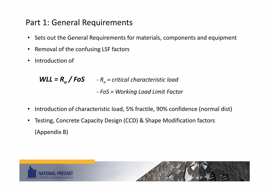
Part 1: General Requirements
• Sets out the General Requirements for materials, components and equipment
• Removal of the confusing LSF factors
• Introduction of
WLL = Ru / FoS - Ru = critical characteristic load
- FoS = Working Load Limit Factor
• Introduction of characteristic load, 5% fractile, 90% confidence (normal dist)
• Testing, Concrete Capacity Design (CCD) & Shape Modification factors
(Appendix B)

Part 1: General Requirements
• Updated Factors of Safety (FoS) to reflect new statistical process

Part 1: General Requirements - cont
• Expanded definitions & notation, incl:
• Erection Designer
• In-service Designer
• Competent person
• f’c,age
• Many more to reflect updated requirements
• Compatibility (Clause 2.1)
“All components to be used on site within the system shall be compatible. Different
proprietary components shall not be mixed without verification of compatibility.
Verification of compatibility shall be proved by testing, and such testing shall be
documented and certified by a competent engineer.”

Part 1: General Requirements - cont
Lifting Anchors (Clause 2.5.2)
• Engineered solutions with focus on testing
• Minimum material properties added to ensure ductility
• Requirement for tension bars in edge lift anchors
• Including integral tension legs
• Test to prove nett increase in anchor capacity from
tension bar
• Component reinforcement as per AS/NZS 4671
• Requirement for system testing in concrete
• Additional testing in Appendix A – A6 & A7
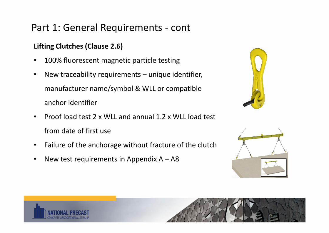
Part 1: General Requirements - cont
Lifting Clutches (Clause 2.6)
• 100% fluorescent magnetic particle testing
• New traceability requirements – unique identifier,
manufacturer name/symbol & WLL or compatible
anchor identifier
• Proof load test 2 x WLL and annual 1.2 x WLL load test
from date of first use
• Failure of the anchorage without fracture of the clutch
• New test requirements in Appendix A – A8

Part 1: General Requirements - cont
Post Installed Brace Anchors (Clause 2.5.3)
• Committee worked closely with AEFAC*
• Completely new test regime in Appendix A – A9
• Test regime now includes cyclic testing
• Expected downgrade in capacities
• Addresses one of the main areas of ambiguity in the
2003 edition
• Notes added on importance of correct drilling of holes
& tightening to correct torque
• Visible identification of supplier after installation
* AEFAC – Australian Engineered Fasteners & Anchors Council (Swinburne University Melbourne)

Part 1: General Requirements - cont
Cast-in Inserts - Ferrules (Clause 2.5.4)
• Bolt lengths, grades & torques to be provided
• Information to be included in erection documentation
• Minimum steel capacity (in tension) of the insert
greater than a 4.6 grade bolt
• Importance of matching threads – insert & bolt
• Additional test requirements in Appendix A – A7

Part 1: General Requirements - cont
Braces (Clause 2.7)
• Additional safety/anti-tampering requirements
• Shear pins can’t be undone without a tool
• Brace feet designed to prevent lateral displacement
• Information available on site for erection crew
• New Inspection & Maintenance requirements
• Repair work to be approved by competent person
• New testing requirements in Appendix A – A10
• ‘Worse case scenario’ with braces horizontal
• Brace feet at specified inclined angles

Part 1: General Requirements - cont
Shims (Clause 2.8)
• Shall be permanently marked to be traceable and
have a marked WLL
• Consideration of temporary vs permanent support
• Minimum width 100mm, length 150mm
• or width/length of element if less
• Maximum total height not to exceed 40mm
• New testing requirements in Appendix A – A11
• Focused on minimising creep & plastic
shrinkage

Part 1: General Requirements - cont
Testing Roadmap

Part 1: General Requirements - cont
Other General points
• Expanded test report requirements
• 5% fractile at a 90% confidence level using a Normal Distribution to validate
the Design (‘Design Validation’)
• High level production validation requirements (‘Production Validation’)
• Introduction of Appendix B (CCD Method – EN/TS 1992-4-2:2009)
Concrete Capacity Design for Cast-In Lifting & Brace Inserts
• Appendix B can be used for standard headed inserts (reference insert) +
inserts with a shape modification factor

Part 1: General Requirements - cont
SUMMARY
Industry should have greater confidence in the products
that they are specifying and using

Agenda
• The AS3850 journey
• Catalyst for updating the standard
• Major changes from 2003 to 2015
• Part 1: General Requirements
• Part 2: Building Construction
• High level summary by Stakeholder
• Alignment with the NCOP
• Questions

Part 2: Building Construction
• Covers all prefabricated concrete elements
(excludes civil and small precast items bricks, blocks)
• Alignment of scope with the NCOP
• Introduces the terms:
In-service Designer – responsible for the In-service Design
Erection Designer – responsible for the Erection Design
• Part 2 is focused on the Erection Design only
• Focuses on the interrelation of the various stages of manufacture,
construction, transport and erection
• Includes new terminology, particularly around concrete strength/time
• Highlights importance of stability & avoiding progressive collapse

Part 2: Building Construction – cont.
Design for Manufacture, Handling & Erection (Clause 2.5)
• Weight of the element is considered the ‘dead load’
• Greater clarity on additional factors during lifting/handling
• Sling Angle Factor
• Dynamic Factor (updated factors)
• Suction Factor
• Service Life Factor (NEW)
• ‘Dead load’ to be multiplied by appropriate factors at different stages:
• At the time of lift-off from casting bed
• Applied load = Dead load x Suction factor x Sling Angle factor
• After lift-off from the bed
• Applied load = Dead load x Dynamic factor x Sling Angle factor x Service life factor
= Applied Load per lifting point

Part 2: Building Construction – cont.
Design for Manufacture, Handling & Erection (Clause 2.5) – cont.
• Scale of additional factors needs to be considered:
• Suction factor – could be > 100% of dead load
• Dynamic factor – could be > 500% of dead load
• Sling Angle Factor – could be > 200% of dead load
Part 2: Building Construction – cont.
Design for Manufacture, Handling & Erection (Clause 2.5) – cont.
• Service Life Factor*:
“Where the application of the PCE (Prefabricated Concrete Element) requires that it be
lifted repetitively during its service life, a service life factor of 1.6 shall be used”
• The re-use of lifting inserts:
“Provided that the lifting inserts have never been loaded past their WLL, there is no
physical deformation or corrosion of the insert, the concrete is still sound and in its
original state, and the loads are and have been applied at low speeds and at low
frequency, the lifting inserts will continue to perform their design task.”
* Does not include the normal multi-handling required in manufacture, handling and erection

Part 2: Building Construction – cont.
Design for Manufacture, Handling & Erection (Clause 2.5) – cont.
• Introduction of additional types of lifting:
• Flat lifting
• Edge lifting
• Face lifting (‘Tilt-Up’ method)
• Mid-air rotation
• Numerous additional examples of typical rigging configurations
Critical to ensure that the lifting
anchor positions and rigging systems
are designed to equalise the loads
Part 2: Building Construction – cont.
Design for Manufacture, Handling & Erection (Clause 2.5) – cont.
• Important rigging/lifting insert position considerations (not full list)
• Fixed leg slings to a common point ≠ load equalisation
• Included angle between legs of multi-leg slings ≤ 1200
• Load transfer to single lifting inserts in mid-air rotation could ≥ 75%
• Rigging systems design to ensure no operators in drop zone
• Importance of correct snatch block if rotation is required
• Geometric centre of lifting inserts vs centre of gravity of element
• Face-lifted elements should be designed to hang ≤ 100 from vertical
• Slenderness of element and possible need for additional support

Part 2: Building Construction – cont.
Design for Manufacture, Handling & Erection (Clause 2.5) – cont.
• Lifting insert capacity
“Bars placed around the foot of the lifting insert typically
provide no additional lifting capacity to the insert”

Part 2: Building Construction – cont.
Design for Manufacture, Handling & Erection (Clause 2.5) – cont.
• Greater focus/commentary on stability
• Effects of eccentric loads on capacity of brace inserts/feet
• Cast-in inserts to be specified by an engineer and included in documentation
• Factors to consider when specifying type, loads and locations of inserts

Part 2: Building Construction – cont.
Design for Manufacture, Handling & Erection (Clause 2.5) – cont.
• Updated section and commentary on Wind loads for temporary supports
• Reference to Tables F1 and F2 of Appendix F of AS/NZS 1170.0:2002
• Terrain category, region, wind speed to be included in documentation
• Design of elements for manufacture, transport and erection
• Must consider bending stresses – cracked vs un-cracked sections
• Importance of crack width if designing on basis of cracked section
• Wall panels (to be transported) should include at least one continuous
perimeter bar
• Additional considerations where extra reinforcement may be required

Part 2: Building Construction – cont.
Design for Manufacture, Handling & Erection (Clause 2.5) – cont.
• Bracing for both horizontal & vertical elements – Braces vs Props
• Significantly expanded list of factors to consider in the design
• Expanded commentary on the design/selection/use of braces/props
• Particular commentary on pre-stressed members & change in load
distribution on prop supports/frames
• Importance of considering construction loads
• Location (to be specified) and number of localised supports
• Columns – one
• Thin elements – two
• Wide horizontal elements – three
Need to consider load eccentricities
on discrete supports/footings

Part 2: Building Construction – cont.
Footings (Clause 2.7)
• Permanent vs Temporary
• Importance of correct shims to take the load
• Overall shim area > bearing strength of footing
• Erection sequence & eccentric loads
• Geotech reports for soil conditions
• Particularly if using screw piles as temporary supports
• Concrete specification vs brace insert strength at time of bracing
• Commonly requires early-age strength concrete
• Size of footings to consider things such as edge distances of post-installed
anchors, vertical and horizontal loads

Part 2: Building Construction – cont.
Connections (Clause 2.8)
• Horizontal restraint at the base of elements during construction
• Fixing system to be used to resist in-service loads
• Superimposed loads and their impact on braces/props
Strongbacks (Clause 2.9)
• Can be required to reduce deflection
and/or control movement
• Preference for cast-in inserts
• Anti-loosening devices recommended
under head of bolt
Fixing as specif ied by an engineer
and insta l led in accordance with the
manufacturer’s specif icat ion
Inser t bolt with
plate and washer
Steel sect ions
(b) Strongback—Steel
Part 2: Building Construction – cont.
Documentation (Clause 2.10)
• Structural vs Manufacture vs Erection drawings
• Manufacture and erection drawings can be one in the same
• Note that Manufacturing drawings are often referred to as Shop drawings
• Appendix A provides guidance on requirements
• Manufacture drawings to be approved by In-Service and Erection Designer
• Erection drawings to be provided/certified by the Erection Designer

Part 2: Building Construction – cont.
Sample of Appendix A

Part 2: Building Construction – cont.
Tolerances (Clause 2.11)
• Tolerances from AS3610 and the Precast
Concrete Handbook (NPCAA) introduced
• Pre-stressed element tolerances added
• Tolerances for a completed structure added
• Techniques added to measure
• Total accumulation of tolerances ≤ 20mm

Part 2: Building Construction – cont.
Casting (Section 3)
• Wording change to include all elements
• Manufacture to approved shop drawings
• Selection of appropriate surface finish
• All elements to be uniquely marked
• Introduces digital photography to support QA
• Section on compaction added
• Element release from casting bed added
• Written authorization suggested for changes

Part 2: Building Construction – cont.
Transport, Cranage & Erection (Section 4)
• Focus on stability of the element/load
• Expanded ‘Erection Preparation’ checklist
• Design of ground supports/platforms
• Expanded commentary of lifting & placing
• Especially if edge-lifting & storing
• Crane specification incl load indicators
• Rigging system as per erection documentation
• Importance of element inspection prior to unloading/lifting
• Ideally braces should be fixed to element prior to lifting
• Checklist to help ensure safe lifting and placement

Part 2: Building Construction – cont.
Temporary Supports (Sections 5 & 6)
• Focus on following the Erection documentation unless approved otherwise
• Importance of not moving/removing without correct approvals
• Application of correct tightening torques
• Additional superimposed loads
• Shims as per new test procedures
• Specification of grout required on Erection
documentation
• Progressive inspections of the structure
to ensure stability prior to removal of any
temporary supports
Part 2: Building Construction – cont.
SUMMARY
Part 2 is specifically for the construction design and
documentation of prefabricated concrete elements in
building construction. The key is the
ERECTION DESIGN and the ERECTION DESIGNER

Agenda
• The AS3850 journey
• Catalyst for updating the standard
• Major changes from 2003 to 2015
• Part 1: General Requirements
• Part 2: Building Construction
• High level summary by Stakeholder
• Alignment with the NCOP
• Questions

High level summary by Stakeholder
In-Service Designer
• Design to incorporate the benefits of prefabricated concrete
• Provide at least one safe method of construction
Erection Designer
• Early consultation and finalisation of erection design prior to work
commencing
• Communication of erection design to all stakeholders is critical to success
Prefabricated Concrete Element Manufacturer
• Follow the approved manufacture (shop) drawings
• Seek approval from Erection Designer before altering anything

High level summary by Stakeholder – cont.
Erection Crew
• Follow the approved Erection Documentation
• Ensure compatibility of components (lifting, bracing & fixing)
Component Supplier/Manufacturer
• Update performance specifications inline with new testing requirements
• Work with industry to ensure a smooth transition of new information/products
Industry Associations/Unions
• Organise educational sessions to promote the new standard
• Work with industry to assist in a smooth transition to the new requirements

Agenda
• The AS3850 journey
• Catalyst for updating the standard
• Major changes from 2003 to 2015
• Part 1: General Requirements
• Part 2: Building Construction
• High level summary by Stakeholder
• Alignment with the NCOP
• Questions
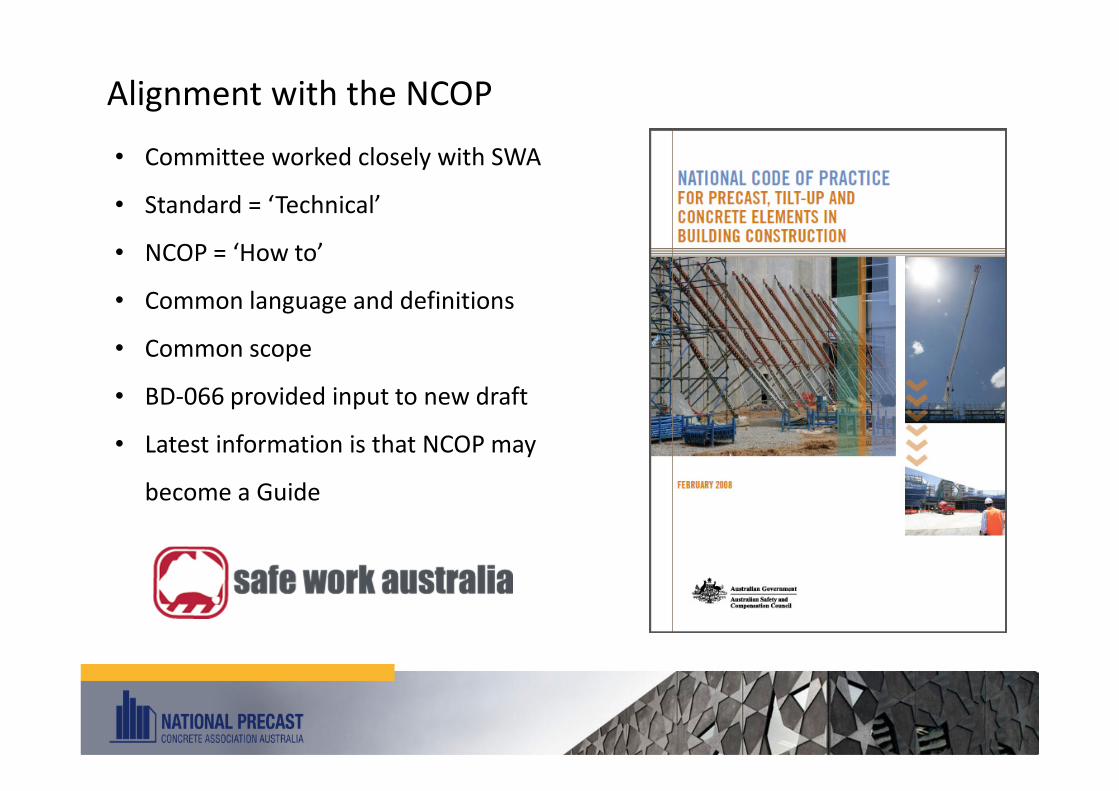
Alignment with the NCOP
• Committee worked closely with SWA
• Standard = ‘Technical’
• NCOP = ‘How to’
• Common language and definitions
• Common scope
• BD-066 provided input to new draft
• Latest information is that NCOP may
become a Guide

Thank you and are
there any questions
I would like to acknowledge National Precast and Reid Construction Systems for
their support of my participation in the update of the standard


![Performance evaluation of smart prefabricated concrete elementsdzonta/download/Publications/[A9]-SSS... · 2015-10-21 · Performance evaluation of smart prefabricated concrete elements](https://img.dokumen.tips/doc/110x75/5ede5c7bad6a402d6669af1b/performance-evaluation-of-smart-prefabricated-concrete-dzontadownloadpublicationsa9-sss.jpg)