Embed Size (px)
Citation preview

Model 95
Autocutter
Operator Manual
95-9000US July 1999
Spartanics Model 95Autocutter
U.S.A.

95-9000US July 1999
Spartanics Model 95Autocutter
Spartanics
Model 95 Autocutter
Operator Manual
U.S.A. Edition
The information furnished herein is believed to be accurate and reliable. However, no
responsibility is assumed by Spartanics for damages incurred directly or indirectly from errors,
omissions or discrepancies between the product and this manual.
Spartanics Ltd. reserves the right to change specifications at any time without notice.
For information not contained in this manual, contact Spartanics
Technical Services Department for assistance.
Spartanics is a registered trademark of Spartanics Ltd. Rolling Meadows, Illinois.

Table of Contents
Introduction 1-1
Model 95 Autocutter · · · · · · · · · · · · · · · · · · · 1-1Features . . . . . . . . . . . . . . . . . . . . . . . . . . . . . . . 1-1
Benefits . . . . . . . . . . . . . . . . . . . . . . . . . . . . . . . 1-1
System Identification · · · · · · · · · · · · · · · · · · 1-1Nameplate Location. . . . . . . . . . . . . . . . . . . . . . 1-1
Spartanics 2-1
Address: · · · · · · · · · · · · · · · · · · · · · · · · · · · · 2-1
Sales · · · · · · · · · · · · · · · · · · · · · · · · · · · · · · · 2-1
Service· · · · · · · · · · · · · · · · · · · · · · · · · · · · · · 2-1
World Wide Web · · · · · · · · · · · · · · · · · · · · · 2-1
Technical Data 3-1
Model · · · · · · · · · · · · · · · · · · · · · · · · · · · · · · 3-1
Material · · · · · · · · · · · · · · · · · · · · · · · · · · · · · 3-1Material Types . . . . . . . . . . . . . . . . . . . . . . . . . . 3-1
Sheet Length . . . . . . . . . . . . . . . . . . . . . . . . . . . 3-1
Sheet Width . . . . . . . . . . . . . . . . . . . . . . . . . . . . 3-1
Sheet Thickness . . . . . . . . . . . . . . . . . . . . . . . . . 3-1
Stack Height. . . . . . . . . . . . . . . . . . . . . . . . . . . . 3-1
Stack Weight . . . . . . . . . . . . . . . . . . . . . . . . . . . 3-1
Hardware· · · · · · · · · · · · · · · · · · · · · · · · · · · · 3-1Dimensions, Overall . . . . . . . . . . . . . . . . . . . . . 3-1
Dimensions, Shipping . . . . . . . . . . . . . . . . . . . . 3-1
Weights . . . . . . . . . . . . . . . . . . . . . . . . . . . . . . . 3-2
Requirements · · · · · · · · · · · · · · · · · · · · · · · · 3-2Power Requirements . . . . . . . . . . . . . . . . . . . . . 3-2
95-9000US July 1999 i-i
Spartanics Model 95Autocutter

Air Requirements . . . . . . . . . . . . . . . . . . . . . . . . 3-2
Throughput. . . . . . . . . . . . . . . . . . . . . . . . . . . . . 3-2
Operating Conditions · · · · · · · · · · · · · · · · · · 3-2Temperature . . . . . . . . . . . . . . . . . . . . . . . . . . . . 3-2
Humidity . . . . . . . . . . . . . . . . . . . . . . . . . . . . . . 3-2
Altitude . . . . . . . . . . . . . . . . . . . . . . . . . . . . . . . 3-2
Manual 4-1
Symbols· · · · · · · · · · · · · · · · · · · · · · · · · · · · · 4-1
General Safety 5-1
General guidelines for safety · · · · · · · · · · · · 5-1General. . . . . . . . . . . . . . . . . . . . . . . . . . . . . . . . 5-1
Responsibilities . . . . . . . . . . . . . . . . . . . . . . . . . 5-1
Operator Requirements . . . . . . . . . . . . . . . . . . . 5-2
Malfunction Procedures . . . . . . . . . . . . . . . . . . . 5-2
Safety Rules . . . . . . . . . . . . . . . . . . . . . . . . . . . . 5-2
Special Safety Warnings 6-1
Integration Compliance· · · · · · · · · · · · · · · · · 6-1
Guarding Warning · · · · · · · · · · · · · · · · · · · · 6-1
Interface Warning · · · · · · · · · · · · · · · · · · · · · 6-1
Input Power Compliance· · · · · · · · · · · · · · · · 6-1
Safety codes · · · · · · · · · · · · · · · · · · · · · · · · · 6-1
Specific Safety Warnings 7-1
Safety Devices · · · · · · · · · · · · · · · · · · · · · · · 7-4Protective Equipment. . . . . . . . . . . . . . . . . . . . . 7-4
Setup 8-1
Uncrating· · · · · · · · · · · · · · · · · · · · · · · · · · · · 8-1
95-9000US July 1999 i-ii
Spartanics Model 95Autocutter

Conveyor Extension · · · · · · · · · · · · · · · · · · · 8-2Attach conveyor extension. . . . . . . . . . . . . . . . . 8-2
Air Connection · · · · · · · · · · · · · · · · · · · · · · · 8-2Attach air line to Auto-cutter . . . . . . . . . . . . . . . 8-2
Electronics Package · · · · · · · · · · · · · · · · · · · 8-3
Electrical · · · · · · · · · · · · · · · · · · · · · · · · · · · · 8-4
Theory of Operation 9-1
Sensors · · · · · · · · · · · · · · · · · · · · · · · · · · · · · 9-1
Drive Assemblies · · · · · · · · · · · · · · · · · · · · · 9-1
Programming Options· · · · · · · · · · · · · · · · · · 9-2
Programming Options 10-1
Scrap-Mark List · · · · · · · · · · · · · · · · · · · · · 10-1Position: . . . . . . . . . . . . . . . . . . . . . . . . . . . . . . 10-1
Type: . . . . . . . . . . . . . . . . . . . . . . . . . . . . . . . . 10-1
Contrast:. . . . . . . . . . . . . . . . . . . . . . . . . . . . . . 10-1
Auto Gain Control: . . . . . . . . . . . . . . . . . . . . . 10-2
Line Width: . . . . . . . . . . . . . . . . . . . . . . . . . . . 10-2
Near Side Gain: . . . . . . . . . . . . . . . . . . . . . . . . 10-2
Far Side Gain . . . . . . . . . . . . . . . . . . . . . . . . . . 10-2
Window Width. . . . . . . . . . . . . . . . . . . . . . . . . 10-2
Skew Limit. . . . . . . . . . . . . . . . . . . . . . . . . . . . 10-3
Quick Window. . . . . . . . . . . . . . . . . . . . . . . . . 10-3
Register Mark List · · · · · · · · · · · · · · · · · · · 10-3First Mark Offset . . . . . . . . . . . . . . . . . . . . . . . 10-3
Step-Up . . . . . . . . . . . . . . . . . . . . . . . . . . . . . . 10-3
Type: . . . . . . . . . . . . . . . . . . . . . . . . . . . . . . . . 10-4
Contrast:. . . . . . . . . . . . . . . . . . . . . . . . . . . . . . 10-4
Auto Gain Control: . . . . . . . . . . . . . . . . . . . . . 10-4
Line Width: . . . . . . . . . . . . . . . . . . . . . . . . . . . 10-4
Near Side Gain: . . . . . . . . . . . . . . . . . . . . . . . . 10-5
95-9000US July 1999 i-iii
Spartanics Model 95Autocutter

Far Side Gain . . . . . . . . . . . . . . . . . . . . . . . . . . 10-5
Window Width. . . . . . . . . . . . . . . . . . . . . . . . . 10-5
Skew Limit. . . . . . . . . . . . . . . . . . . . . . . . . . . . 10-5
Quick Window. . . . . . . . . . . . . . . . . . . . . . . . . 10-5
Feed List · · · · · · · · · · · · · · · · · · · · · · · · · · · 10-5Lead Scrap Yes/No . . . . . . . . . . . . . . . . . . . . . 10-5
Tail Scrap Yes/No . . . . . . . . . . . . . . . . . . . . . . 10-6
Middle Scrap Yes/No. . . . . . . . . . . . . . . . . . . . 10-6
Scrap Offset . . . . . . . . . . . . . . . . . . . . . . . . . . . 10-6
Strips per Sheet . . . . . . . . . . . . . . . . . . . . . . . . 10-6
Feed Rate . . . . . . . . . . . . . . . . . . . . . . . . . . . . . 10-6
Feed Acceleration . . . . . . . . . . . . . . . . . . . . . . 10-6
Sheet Pickup Delay . . . . . . . . . . . . . . . . . . . . . 10-7
Sheet Hold Delay . . . . . . . . . . . . . . . . . . . . . . . 10-7
Sheet Insert Delay . . . . . . . . . . . . . . . . . . . . . . 10-7
Scrap Eject Delay. . . . . . . . . . . . . . . . . . . . . . . 10-7
Register List · · · · · · · · · · · · · · · · · · · · · · · · 10-7Input Register Near Mark Placement. . . . . . . . 10-7
Input Register Far Mark Placement . . . . . . . . . 10-7
Output Register Near Mark Placement . . . . . . 10-8
Output Register Far Mark Placement . . . . . . . 10-8
Output Register Near Last Correction . . . . . . . 10-8
Output Register Far Last Correction . . . . . . . . 10-8
Geometry List · · · · · · · · · · · · · · · · · · · · · · · 10-8Sensor Position Custom / At Edges . . . . . . . . . 10-8
Input Sensor to Blade. . . . . . . . . . . . . . . . . . . . 10-9
Output Sensor to Blade . . . . . . . . . . . . . . . . . . 10-9
Totals List · · · · · · · · · · · · · · · · · · · · · · · · · · 10-9Total Sheets Processed. . . . . . . . . . . . . . . . . . . 10-9
Total Strips Processed . . . . . . . . . . . . . . . . . . . 10-9
Total Shear Cuts. . . . . . . . . . . . . . . . . . . . . . . . 10-9
Reset All question . . . . . . . . . . . . . . . . . . . . . 10-10
Configure List · · · · · · · · · · · · · · · · · · · · · · 10-10Language . . . . . . . . . . . . . . . . . . . . . . . . . . . . 10-10
95-9000US July 1999 i-iv
Spartanics Model 95Autocutter

Dimension Units . . . . . . . . . . . . . . . . . . . . . . 10-10
Load/Save Job# . . . . . . . . . . . . . . . . . . . . . . . 10-10
Load from Job question . . . . . . . . . . . . . . . . . 10-10
Save to Job question . . . . . . . . . . . . . . . . . . . 10-10
Keypad Revision . . . . . . . . . . . . . . . . . . . . . . 10-10
Controller Revision . . . . . . . . . . . . . . . . . . . . 10-11
Operating Mode . . . . . . . . . . . . . . . . . . . . . . . 10-11
Control Panel 11-1
Push Buttons · · · · · · · · · · · · · · · · · · · · · · · · 11-1Emergency Stop pushbutton: . . . . . . . . . . . . . 11-1
ON pushbutton: . . . . . . . . . . . . . . . . . . . . . . . . 11-2
OFF pushbutton . . . . . . . . . . . . . . . . . . . . . . . . 11-2
Lower-Off-Raise Switch: . . . . . . . . . . . . . . . . 11-2
Sheet Feed RESET Button: . . . . . . . . . . . . . . . 11-3
Operators Keypad And Display: · · · · · · · · · 11-3Alpha keys . . . . . . . . . . . . . . . . . . . . . . . . . . . . 11-4
Plus & Minus . . . . . . . . . . . . . . . . . . . . . . . . . . 11-4
Reset. . . . . . . . . . . . . . . . . . . . . . . . . . . . . . . . . 11-5
Setup . . . . . . . . . . . . . . . . . . . . . . . . . . . . . . . . 11-5
Run. . . . . . . . . . . . . . . . . . . . . . . . . . . . . . . . . . 11-5
Sensor. . . . . . . . . . . . . . . . . . . . . . . . . . . . . . . . 11-6
Jog . . . . . . . . . . . . . . . . . . . . . . . . . . . . . . . . . . 11-6
Advance . . . . . . . . . . . . . . . . . . . . . . . . . . . . . . 11-7
Icons and Labels 12-1
Chasis Informational Labels · · · · · · · · · · · · 12-1Sensor Icons. . . . . . . . . . . . . . . . . . . . . . . . . . . 12-1
Drive Icons. . . . . . . . . . . . . . . . . . . . . . . . . . . . 12-3
Air Control - Main Identification. . . . . . . . . . . 12-4
Air Switches (Input Side) . . . . . . . . . . . . . . . . 12-5
Air Switches Output side) . . . . . . . . . . . . . . . . 12-7
Functions.. . . . . . . . . . . . . . . . . . . . . . . . . . . . . 12-7
Icons - Electrical Control Box. · · · · · · · · · · 12-8
Icons - Control Panel & Housing.· · · · · · · 12-10
95-9000US July 1999 i-v
Spartanics Model 95Autocutter

Control Panel. . . . . . . . . . . . . . . . . . . . . . . . . 12-10
Table Lift . . . . . . . . . . . . . . . . . . . . . . . . . . . . 12-11
Setup 13-1
Basic Setup · · · · · · · · · · · · · · · · · · · · · · · · · 13-1Setting registration mark locations. . . . . . . . . 13-1
Set approximate cutting locations . . . . . . . . . . 13-1
Fine tuning the cutting locations . . . . . . . . . . . 13-1
Startup Conditions · · · · · · · · · · · · · · · · · · · 13-2
Set Registration mark locations. · · · · · · · · · 13-4Set Scrap Mark Position (A1) . . . . . . . . . . . . . 13-4
Set First Mark Offset . . . . . . . . . . . . . . . . 13-4
Set Step up (B2). . . . . . . . . . . . . . . . . . . . . . . . 13-5
Set approximate cutting locations · · · · · · · · 13-6Setup Feed Sheet . . . . . . . . . . . . . . . . . . . . . . . 13-6
Setup Near Scrap cut . . . . . . . . . . . . . . . . . . . . 13-6
Setup Far Scrap cut . . . . . . . . . . . . . . . . . . . . . 13-6
Setup Center Cut . . . . . . . . . . . . . . . . . . . . . . . 13-7
Set Near Center cut position . . . . . . . . . . . . . . 13-7
Set Far Center cut position. . . . . . . . . . . . . . . . 13-7
Setup Last Cut . . . . . . . . . . . . . . . . . . . . . . . . . 13-7
Set Near Last Correction . . . . . . . . . . . . . . . . . 13-7
Set Far Last Correction . . . . . . . . . . . . . . . . . . 13-7
End Approx. Setup. . . . . . . . . . . . . . . . . . . . . . 13-8
Fine tune cutting locations · · · · · · · · · · · · · 13-9Setup Run / Pause Mode . . . . . . . . . . . . . . . . . 13-9
Setup- Fine tune cuts . . . . . . . . . . . . . . . . . . . . 13-9
Fine tune Scrap cut . . . . . . . . . . . . . . . . . . . . 13-10
Fine tune Center cut. . . . . . . . . . . . . . . . . . . . 13-11
Fine Tune Last Cut . . . . . . . . . . . . . . . . . . . . 13-12
Setup (Pause / Run) ends . . . . . . . . . . . . . . . . 13-13
Operation 14-1
Setup · · · · · · · · · · · · · · · · · · · · · · · · · · · · · · 14-1
95-9000US July 1999 i-vi
Spartanics Model 95Autocutter

Apply Main Power. . . . . . . . . . . . . . . . . . . . . . 14-1
Check Air Pressure . . . . . . . . . . . . . . . . . . . . . 14-1
Check Oil Level . . . . . . . . . . . . . . . . . . . . . . . . 14-2
Turn Electronics ON . . . . . . . . . . . . . . . . . . . . 14-2
Normal Run Operation · · · · · · · · · · · · · · · · 14-3Load Material. . . . . . . . . . . . . . . . . . . . . . . . . . 14-3
Start Operation. . . . . . . . . . . . . . . . . . . . . . . . . 14-4
Shutdown . . . . . . . . . . . . . . . . . . . . . . . . . . . . . 14-5
Troubleshooting Guide 15-1
Sheet Separating Problems · · · · · · · · · · · · 15-1Intermittent Jet (Floater Jet) - One Jet . . . . . . 15-1
Continuous Jets (Separator Jets) - Two Jets . . 15-1
Sheet Delays . . . . . . . . . . . . . . . . . . . . . . . . . . 15-1
Sheet Pull-Back Backstops - (Two Stops) . . . 15-1
Pick-Up Head / Vacuum Cups . . . . . . . . . . . . 15-2
Other - Tricks-of-the-Trade . . . . . . . . . . . . . . 15-2
Sheet Pick-up Problems · · · · · · · · · · · · · · · 15-2Continuous Jets(Separator Jets) - Two Jets . . 15-2
Pick-up Head Height Adjustment . . . . . . . . . . 15-2
Pull-Back Backstops - (Two Stops) . . . . . . . . 15-3
Vacuum Generator Flow Control . . . . . . . . . . 15-3
Vacuum Cups - (Three) . . . . . . . . . . . . . . . . . 15-3
Sheet Feeding Problems · · · · · · · · · · · · · · · 15-3Stack Location . . . . . . . . . . . . . . . . . . . . . . . . 15-3
Nearside Drive Assembly (Stationary) . . . . . . 15-4
Farside Drive Assembly (Adjustable) . . . . . . . 15-4
Drive Assemblies (Near and Far Side) . . . . . . 15-4
Roller Bar (Suspends above the Bottom Blade) . . . . . . . 15-4
Input Guiding Fingers (Near and Far Side) . . . . . . . 15-4
Pull-Back Backstops (Two Stops) . . . . . . . . . 15-5
Scrap Ejector Nozzles (Two Nozzles) . . . . . . 15-5
Roller Blocks (Number Varies w/ Sheet Width) . . . . . . 15-5
Lip Switch (Intermittently Activates the Table Lift Motor) . 15-5
Stack Safety Limit Switch . . . . . . . . . . . . . . . 15-6
95-9000US July 1999 i-vii
Spartanics Model 95Autocutter

Stack Height . . . . . . . . . . . . . . . . . . . . . . . . . . 15-6
Front Stack Guides (Three) . . . . . . . . . . . . . . . 15-6
Bad Lamination . . . . . . . . . . . . . . . . . . . . . . . . 15-7
Shearing Problems · · · · · · · · · · · · · · · · · · · 15-7Guards (Input & Output) . . . . . . . . . . . . . . . . . 15-7
Air Pressure . . . . . . . . . . . . . . . . . . . . . . . . . . . 15-7
Double Feed . . . . . . . . . . . . . . . . . . . . . . . . . . 15-7
Scrap Failed to Fully Eject . . . . . . . . . . . . . . . 15-7
Blade Pre-Load Tension . . . . . . . . . . . . . . . . . 15-7
Sensing Problems · · · · · · · · · · · · · · · · · · · · 15-8Sensor Placement . . . . . . . . . . . . . . . . . . . . . . 15-8
Sensor to Material Gap . . . . . . . . . . . . . . . . . . 15-8
Color / Job Change of the Shear Reg. Marks . 15-8
Parts Listing SAFETY LABELS 16-1
Parts List - Spares 17-1
Schematics 18-1
Appendix 1 20-1
Programming chart · · · · · · · · · · · · · · · · · · · 20-1
Appendix 2 21-1Artwork Specifications . . . . . . . . . . . . . . . . . . 21-1
95-9000US July 1999 i-viii
Spartanics Model 95Autocutter

1. Introduction
1.1. Model 95 Autocutter
The Model 95 Autocutter is designed as the first station in a Spartanics
Model 500 sheet to card system. A stack of laminated sheets can be trimmed
and automatically delivered into a Spartanics Card Blanking System.
1.1.1. Features
• Fully integrated front end for M500
• Optically registers, then cuts material into strip stock.
• Automatically feeds into blanking press
• Material stacking pre-station
• Multilingual control panel
• Metric / inches convertibility
1.1.2. Benefits
• Complete system automation
• Minimize material handling
• Consistent accuracy
• High speed, high output production
• Minimum loading down times
• Quick, easy job setups
• Ease of use
• Scratch free handling.
1.2. System Identification
1.2.1. Nameplate Location
95-0000US July 1999 1-1
Spartanics Model 95 Introduction

2. Spartanics
2.1. Address:Spartanics, Ltd.
3605 Edison Place
Rolling Meadows, IL 60008
U.S.A.
2.2. SalesTel: 847-394-5700
Fax: 847-394-0409
2.3. ServiceTel: 847-394-5700
Fax: 847-394-9349
2.4. World Wide WebHttp:www\\spartanics.com
95-0000US July 1999 2-1
Spartanics Model 95 Spartanics

3. Technical Data
3.1. ModelModel 95
3.2. Material
3.2.1. Material Types
Most plastics
3.2.2. Sheet Length
Minimum. . . . . . . . . . . . . . . . 11.5 . . . . (29.2 cm)
Maximum . . . . . . . . . . . . . . . . 30” . . . . . ( 76 cm)
3.2.3. Sheet Width
Minimum . . . . . . . . . . . . . . . . 12” . . . . . (30 cm)
Maximum . . . . . . . . . . . . . . . . 29” . . . . . (73 cm)
3.2.4. Sheet Thickness
Minimum. . . . . . . . . . . . . . 0.010” . . . (0.25 mm)
Maximum . . . . . . . . . . . . . 0.035” . . . . (0.9 mm)
3.2.5. Stack Height
Maximum . . . . . . . . . . . . . . . . 18” . . . . . (45 cm)
(Approximately 500 sheets of CR80)
3.2.6. Stack Weight
Maximum . . . . . . . . . . . . 600 LB . . . . (272 Kg)
3.3. Hardware
3.3.1. Dimensions, Overall
Length. . . . . . . . . . . . . . . . . . 100” . . . . (254 cm)
Width . . . . . . . . . . . . . . . . . . . 40” . . . . (100 cm)
Height . . . . . . . . . . . . . . . . . . 65” . . . . (165 cm)
3.3.2. Dimensions, Shipping
Length. . . . . . . . . . . . . . . . . . . 60” . . . . (152 cm)
Width . . . . . . . . . . . . . . . . . . . 84” . . . . (213 cm)
Height . . . . . . . . . . . . . . . . . . . 68” . . . . (173 cm)
95-0000US July 1999 3-1
Spartanics Model 95 Technical Data

3.3.3. Weights
Operational. . . . . . . . . . . . 500 LB. . . . . (227 kg)
Shipping . . . . . . . . . . . . . 700 LB . . . . (318 kg.)
3.4. Requirements
3.4.1. Power Requirements
Power. . . . . . . . . . . . . . . . 600 VA
Volts . . . . . . . . . . 220 - 480 VAC
Frequency . . . . . . . . . . 50 / 60 Hz
3.4.2. Air Requirements
Nominal
4 cfm @ 80 psi (115 L/min @ 5.5 bar)
Maximum
10 cfm @ 110 psi (283 L /min @ 7.6 bar)
3.4.3. Throughput
20 strips per minute
3.5. Operating Conditions
3.5.1. Temperature
Ambient operating range . +5 C to +40 C
3.5.2. Humidity
Ambient operating range 30 - 95% RH
(Non-condensing)
3.5.3. Altitude
Operating range . . . . . . 0 -1000 M
(Above Sea Level)
95-0000US July 1999 3-2
Spartanics Model 95 Technical Data

4. Manual
4.1. Symbols
Warning
Designation of a possible hazardous situation.
If this situation is not prevented, the consequences may
be;
• Unhealthy effects
• Serious injuries
Caution
Designation of a hazardous situation.
If this situation is not prevented, the consequences may
be;
• Slight or minor injuries
• Damage to the equipment.
Important
Designation of special working instructions
Dangerous voltages
Designates parts of the unit with a possible dangerous
voltage
95-0000US July 1999 4-1
Spartanics Model 95 Manual

Head or body injury
Designation of a condition where device may drop or
move which may cause injury
Compressed Air
Designation of an area where compressed air is used.
Injury could result if connections are not made correctly
or damaged parts are used or present.
95-0000US July 1999 4-2
Spartanics Model 95 Manual

5. General Safety
5.1. General guidelines for safety
5.1.1. General
This device conforms to established safety regulations.
However, hazards are involved in the operation of this
device if:
• The operation and safety guide lines in this manual
are not followed.
• The device is not operated for it’s intended use.
5.1.2. Responsibilities
The manufacturer is responsible for delivering the
device in a flawless state in terms of operation and
safety regulations.
The company operating the device is responsible for;
• Ensuring that the device is used in accordance with its
intended purpose;
• Training the personnel
• Providing any required protective gear
• Controlling that only authorized personnel work on
the device;
• Meeting the required maintenance requirements;
The operating personnel is responsible for;
• Operating the device only when it is in a flawless
state with all safety guards properly installed;
• Immediately notifying the supervisor in charge of
anything affecting safety;
• Ensuring that no unauthorized persons are near the
device during operation;
• The use and care of appropriate safety and protective
equipment;
• Cleaning the device and the work area around the
device.
95-0000US July 1999 5-1
Spartanics Model 95 General Safety

5.1.3. Operator Requirements
All persons involved in the operation of this device
shall;
• Be of legal age to operate this type of machinery;
• Be adequately trained and instructed in the operation
of this device;
• Have read and understood all operation and safety
instructions in this manual;
• Have read and understood all local and regional safety
instructions governing the use of this type of
machinery.
Trainees shall only work on this device when supervised
by an experienced operator.
5.1.4. Malfunction Procedures
In the event of any malfunction, turn power off and
contact qualified service personnel.
5.1.5. Safety Rules
• The operation of this device is subject to the local,
state, federal, and international regulations regarding
safety at work and accident prevention.
• Read this manual before operating this device.
• For any operation or maintenance procedures that
may be required, but are not covered in this manual,
contact Spartanics Technical Service Department
before proceeding.
• Before device is put into operation, always check the
safety equipment and protective covers.
• Unauthorized modifications and changes to the device
are not authorized.
• Accessories, replacement, or spare parts produced
from other manufacturers may only be used when
approved by Spartanics
• Before carrying out any maintenance, repair, or
modification work, lockout mains supply voltage to
prevent power from inadvertently being switching on.
• Never operate this device unless it is properly
grounded according to local regulations.
• Never operate this device with any of its safety guards
removed or improperly installed.
• Never operate this device in an explosive atmosphere.
95-0000US July 1999 5-2
Spartanics Model 95 General Safety

• Never operate this device in a wet or moist
environment.
95-0000US July 1999 5-3
Spartanics Model 95 General Safety

6. Special Safety Warnings
6.1. Integration Compliance
Spartanics Autocutter Systems are designed to be integrated into Spartanics Feed
Systems and an end users equipment. Continued compliance with all government
regulations and codes is the responsibility of the end user management.
6.2. Guarding Warning
Attachment of Spartanics Autocutter and / or Feed Assemblies to the users
equipment and automating material movement in no way reduces the need to
adequately guard any hazardous areas. All guarding is the users responsibility.
6.3. Interface Warning
Spartanics Feed Systems provide a “request to trip” signal only. Any interfaces
between the users equipment and the feed system must be done in a way that
insures the integrity of all existing safety, redundancy, and shutdown features of
the end users equipment.
6.4. Input Power Compliance
The Spartanics Autocutter Systems is supplied power from electrical mains. Mains
voltage must be verified with a true RMS meter. Verify equipment is wired correctly
to match mains voltage.
6.5. Safety codes
No information supplied by Spartanics either in written or verbal form regarding
safe installation or operation is intended to supersede local electrical and safety
codes.
95-0000US July 1999 6-1
Spartanics Model 95 Special Safety Warnings

7. Specific Safety Warnings
Warning
Mains voltage is used to operate this device
Possible hazards
Death or injuries due to electrical shock
Safety measures
Covers containing electrical components, controls and
distribution circuits may only be opened by authorized
personnel.
Warning
Automatic movement of the pickup system
Possible hazards
Pinch or compression injury when pickup system is in
motion
Safety measures
• Do not operate device with safety guards removed.
• Do not stop movement with you hands.
• Do not operate press with any other personnel near
machine.
Warning
Foreign object may be ejected from clamp or cutting
area.
Possible hazards
Face, hand, or other injuries due to ejected objects
Safety measures
Wear safety glasses, gloves or other protection
95-0000US July 1999 7-1
Spartanics Model 95 Specific Safety Warnings

Warning
This device uses compressed air
Possible hazards
Injury possible due to loose or broken air fittings or lines
Safety measures
Always verify that air fitting and connections are
securely fastened.
Never use equipment is any fittings or lines show signs
of wear or have any defects. Replace if needed.
Warning
This device has a motorized table that raises and lowers.
Possible hazards
Injury possible if any part of body is caught between
table and frame when table is in motion.
Safety measures
Keep all parts of body clear of frame and table when
table is in motion.
Keep all other people clear of machine when machine is
in operation
Warning
This device uses a roller conveyor to move material onto
a motorized lift table.
Possible hazards
Possible crushing or pinching type injuries to any part of
the body that caught between material moving on the
conveyor and any part of the auto-cutter.
Safety measures
Use caution when moving material on conveyor.
Keep area in front of moving material clear of any
obstruction.
95-0000US July 1999 7-2
Spartanics Model 95 Specific Safety Warnings

Warning
Maximum load on motorized table is 600 lbs. (272 Kg.)
Possible hazards
Injury possible from broken equipment if maximum
load is exceeded .
Safety measures
Never load table with more than 600 lbs. (272 Kg.)
Never place anything on motorized table except material
being processed.
Keep area around machine clear to avoid having
anything fall into table travel area and jamming table
travel.
Warning
This device uses automatic cutting blades to cut material
Possible hazards
Serious injury to fingers possible if fingers are under
blade when machine is in operation.
Safety measures
Do not place fingers under blade when machine is
turned on.
Before adjusting blade or performing and maintenance
in blade area, turn electrical power off, lock power
switch off, and disconnect air supply.
Warning
This device has a motorized table that raises and lowers.
Possible hazards
Possible crushing type injuries to any part of the body
that is in travel area of table when it is moving.
Safety measures
Keep area under the motorized table clear.
Do not operate the auto-cutter with any other personnel
near the machine.
95-0000US July 1999 7-3
Spartanics Model 95 Specific Safety Warnings

Warning
The output table can swing up or down.
Possible hazards
Injury possible if table drops.
Safety measures
Do not place anything on table while it is being
adjusted.
Have an additional person help hold table whenever
adjustments are being made.
Be sure brackets holding table are securely fastened.
7.1. Safety Devices
7.1.1. Protective Equipment
• Close fitting work clothing
• Safety glasses
• Gloves
95-0000US July 1999 7-4
Spartanics Model 95 Specific Safety Warnings

8. Setup
8.1. Uncrating
Caution!
Use safety grasses when removing screws.
Two people are required to remove crate.
Remove Crate top and sides
Remove scrap bin, conveyor extension, & hold down bolts.
Lift Auto-cutter off pallet using a forklift with cargo straps
.
95-0000US July 1999 8-1
Spartanics Model 95 Setup

Install leveling feet before placing on floor.
8.2. Conveyor Extension
8.2.1. Attach conveyor extension
(Extension may be bolted to floor if desired after finalplacement.)
8.3. Air Connection
8.3.1. Attach air line to Auto-cutter
95-0000US July 1999 8-2
Spartanics Model 95 Setup

8.4. Electronics PackageSlide Electronics Package into rack, install mounting screws onfront, connect cables on rear panel.
When connecting drive motor cables, be sure to match icons toinsure proper connections. (Left connector to near motor.)
Air manifold connections:
Input manifold (above input table)
95-0000US July 1999 8-3
Spartanics Model 95 Setup

Output manifold (below output table)
8.5. Electrical
Caution
Electrical connections must only be made by a qualified electrician.
Serious injury may result if improper connections are made!
Transformer is pre wired at the factory for the voltage requestedby the customer. The electrician installing this device must verifythat the actual measured input supply voltage matches thetransformer wiring. A transformer wiring chart is located on theinside door of the power box.
Voltage Chart Location (on back of power box door.)
95-0000US July 1999 8-4
Spartanics Model 95 Setup

Use key to unlock and open power cabinet door.
Using either top or bottom knock out, feed power cable intopower box (secure cable to box with proper cable clamp).
Connect Ground wire to Earth Ground connection and powerwires to L1, L2, and L3 (System is not phase sensitive). Use L2 &L3 for two wire connections.
95-0000US July 1999 8-5
Spartanics Model 95 Setup

9. Theory of Operation
The registration operation of the M95 Auto-Cutter is very similar to the
operation of the M44/M24/M334 decorated material feeds. The sensors are
functionally identical to those used on the feeds, material control uses nip
rolls like the feeds, and many of the programing options are identical to the
feeds.
9.1. Sensors
The Auto-Cutter uses 4 registration sensors total, two on the input side
(before the shear blade) and two on the output side. The two sensors on the
input side are used to register the material for any lead edge scrap cut which
might be required on the sheet. The two output side sensors are used to
register the material for stripping cuts and trailing edge scrap cuts. The
sensors are always used in pairs, two sensors being required to register the
sheet in the feed axis and in rotation.
9.2. Drive Assemblies
There are two nip roller drive assemblies on the Auto-Cutter, a near-side
(operator side) drive and a far-side (non-operator side) drive. While the
position of both assemblies is adjustable, the near side drive normally remains
in a fixed position while the far-side drive is shifted to match the width of the
sheets being processed.
NOTE: Sheet width in a stack needs to be fairly regular, 1/8 inch total
variation is tolerable.
Each drive assembly straddles the blade and contains two nip rolls, an
input side nip and an output side nip. Each nip is actuated (closed) with a
pneumatic cylinder so that the input and output sides may be selectively
engaged and released. There is a single motor/encoder combination for each
drive assembly which is coupled to the two drive wheels with timing belts.
95-0000US July 1999 9-1
Spartanics Model 95 Theory of Operation

Note that unlike the M44/M224/M334 feeds, the encoder does not
measure material motion with an idler wheel but rather is connected directly
to the motor shaft. The Auto-Cutter can not detect material slippage or
sticking and does not know if there is any material in the nips. The only drive
fault that can be detected is one that actually stalls the motor. This detail will
tend to make the Auto-Cutter less accurate than the feed systems. In the best
case, where there is no material slippage, the accuracy will equal that of the
feed systems.
9.3. Programming Options
Operator programming options are very similar to existing feed systems.
The Auto-Cutter requires that a number of parameters be set in order to
run a job. The parameters are accessed in lists with a unique key being used to
select the particular list.
Refer to the Programming Guide Chapter for detailed explanation of
each function.
95-0000US July 1999 9-2
Spartanics Model 95 Theory of Operation

10. Programming Options
The Auto-Cutter requires that a number of parameters be set inorder to run a job. The parameters are accessed in lists with aunique key being used to select the particular list.
The boxes below indicate which LETTER button to press.
The NUMBER in the box indicates the position in the menu theselection is located. A
10.1.Scrap-Mark List
The Scrap-Mark is an optional mark used to locate some featureon the sheet for the purpose of making an initial or lead edgescrap cut on the sheet. Both of the input side sensors are usedwhen reading the Scrap-Mark. With the exception of sensorGAIN, all parameters apply to both the Near Side and Far Sidesensors. The items in the Scrap-Mark list are as follows ...
10.1.1.
Position:
The nominal distance from the lead edge of the sheet to theScrap-Marks.
10.1.2.
Type:
Selects the type of Register Pattern the sensor will be lookingfor. A “LINE” is the normal selection. Options include “NONE”which will disable the sensor.
10.1.3.
Contrast:
Selects the contrast the sensor will be looking for.
Dark contrast is used for a dark printed registration patten on alight background.
Light contrast is used for a light printed registration pattern on adark background.
95-0000US July 1999 10-1
Spartanics Model 95 Programming Options
A
A1
A2
A3

10.1.4.
Auto Gain Control:
Selects the sensor gain mode.
Auto mode: The Auto Cutter will automatically adjust thecurrent Gain setting .
NOTE: Auto mode will not instantly set the Sensor Gain, the Auto Cutter will
adjust the Sensor Gain up or down only AFTER a pattern is sensed.
SETUP mode: The Auto Gain Control may make an adjustmentany time the sensor operates.
RUN mode: The Auto Gain Control will only adjust the gain if a“Good Mark” is sensed.
10.1.5.
Line Width:
Selects the line width the sensor should expect to see. The sensorwill ignore any sensed lines less than ½ the expected width andgreater than 1½ times the expected width. Setting a value ofZERO disables line width checking. Line width checking isrecommended when Quick Window is ON in order to rejectnoise signals which might otherwise be interpreted as a goodmarks.
10.1.6.
Near Side Gain:
Selects and displays the current sensitivity of the near side sensorexpressed as a percent of maximum sensitivity. Low contrastmarks will require a higher percentage sensitivity than highcontrast marks.
10.1.7.
Far Side Gain
Selects and displays the current sensitivity of the far side sensor.
10.1.8.
Window Width
Sets the sensor Window dimension. The window is the distanceover which the sensor will search for the expected RegisterPattern.
95-0000US July 1999 10-2
Spartanics Model 95 Programming Options
A5
A6
A7
A8
A4

10.1.9.
Skew Limit
Sets a maximum allowed sheet rotation limit. If the “SkewLimit” is exceeded the Auto-Cutter will pause and the operatorwill have the option of cutting the sheet or re-sensing the registermarks. The Skew Limit is another means of rejecting noisesignals which might otherwise be interpreted as good marks.
10.1.10.
Quick Window
Enables or disables Quick Window. When enabled, the sensorswill stop scanning (close the window) as soon as the selectedRegister Pattern is detected.
10.2.Register Mark List
The Register-Mark is mark used to locate some feature on thesheet for the purpose of making stripping and tail scrap cuts onthe sheet.
Unlike the Scrap-Mark, which uses the input side sensors, theoutput side sensors are used when reading the Register-Marks.As with the other marks, all parameters apply to both the NearSide and Far Side sensors with the exception of sensor GAIN.
The items in the Register-Mark list are as nearly identical to theitems in the Scrap-Mark list. Where the significance is the sameno additional comments are offered.
10.2.1.
First Mark Offset
The nominal distance from the Scrap-Mark to the firstRegister-Mark.
10.2.2.
Step-Up
The nominal distance between successive Register Marks
95-0000US July 1999 10-3
Spartanics Model 95 Programming Options
A9
A10
B
B1
B2

10.2.3.
Type:
Selects the type of Register Pattern the sensor will be lookingfor. A “LINE” is the normal selection. Options include “NONE”which will disable the sensor.
10.2.4.
Contrast:
Selects the contrast the sensor will be looking for.
Dark contrast is used for a dark printed registration patten on alight background.
Light contrast is used for a light printed registration pattern on adark background.
10.2.5.
Auto Gain Control:
Selects the sensor gain mode.
Auto mode: The Auto Cutter will automatically adjust thecurrent Gain setting .
NOTE: Auto mode will not instantly set the Sensor Gain, the Auto Cutter will
adjust the Sensor Gain up or down only AFTER a pattern is sensed.
SETUP mode: The Auto Gain Control may make an adjustmentany time the sensor operates.
RUN mode: The Auto Gain Control will only adjust the gain if a“Good Mark” is sensed.
10.2.6.
Line Width:
Selects the line width the sensor should expect to see. The sensorwill ignore any sensed lines less than ½ the expected width andgreater than 1½ times the expected width. Setting a value ofZERO disables line width checking. Line width checking isrecommended when Quick Window is ON in order to rejectnoise signals which might otherwise be interpreted as a goodmarks.
95-0000US July 1999 10-4
Spartanics Model 95 Programming Options
B4
B5
B6
B3

10.2.7.
Near Side Gain:
Selects and displays the current sensitivity of the near side sensorexpressed as a percent of maximum sensitivity. Low contrastmarks will require a higher percentage sensitivity than highcontrast marks.
10.2.8.
Far Side Gain
Selects and displays the current sensitivity of the far side sensor.
10.2.9.
Window Width
Sets the sensor Window dimension. The window is the distanceover which the sensor will search for the expected RegisterPattern.
10.2.10.
Skew Limit
Sets a maximum allowed sheet rotation limit. If the “SkewLimit” is exceeded the Auto-Cutter will pause and the operatorwill have the option of cutting the sheet or re-sensing the registermarks. The Skew Limit is another means of rejecting noisesignals which might otherwise be interpreted as good marks.
10.2.11.
Quick Window
Enables or disables Quick Window. When enabled, the sensorswill stop scanning (close the window) as soon as the selectedRegister Pattern is detected.
10.3.Feed List
C
10.3.1.
Lead Scrap Yes/No
Enables or disables the lead edge scrap cut based on theScrap-Mark position. When disabled, the Auto-Cutter will still
95-0000US July 1999 10-5
Spartanics Model 95 Programming Options
B8
B9
B10
B11
C
C1
B7

position and square the sheet at the Scrap-Mark location but theshear blade will not fire.
10.3.2.
Tail Scrap Yes/No
Enables or disables a tail edge scrap cut based on theRegister-Mark position.
10.3.3.
Middle Scrap Yes/No
Enables or disables a mid-sheet scrap cut based on theRegister-Mark position.
10.3.4.
Scrap Offset
The width of the scrap material removed in middle scrap cuts.
10.3.5.
Strips per Sheet
Tells the Auto-Cutter the number of strips to be produced fromeach sheet. This is also the number of Register Marks the sensorswill expect to see.
10.3.6.
Feed Rate
Selects the maximum speed to be used when advancing material.
10.3.7.
Feed Acceleration
Selects the acceleration (low/medium/high) to be used whenadvancing material.
NOTE: Lower feed rates and accelerations will improveaccuracy and reliability of sensing and material handling. Use thelowest settings possible which yield the required throughput.
95-0000US July 1999 10-6
Spartanics Model 95 Programming Options
C3
C2
C4
C5
C6
C7
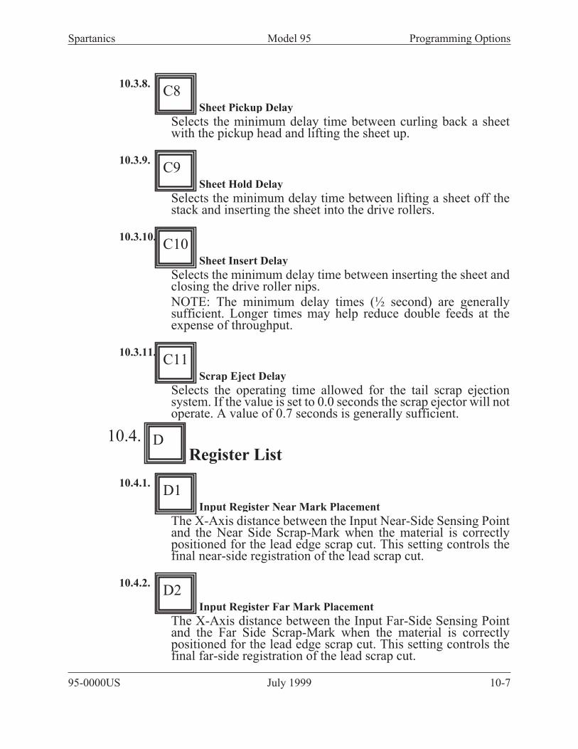
10.3.8.
Sheet Pickup Delay
Selects the minimum delay time between curling back a sheetwith the pickup head and lifting the sheet up.
10.3.9.
Sheet Hold Delay
Selects the minimum delay time between lifting a sheet off thestack and inserting the sheet into the drive rollers.
10.3.10.
Sheet Insert Delay
Selects the minimum delay time between inserting the sheet andclosing the drive roller nips.
NOTE: The minimum delay times (½ second) are generallysufficient. Longer times may help reduce double feeds at theexpense of throughput.
10.3.11.
Scrap Eject Delay
Selects the operating time allowed for the tail scrap ejectionsystem. If the value is set to 0.0 seconds the scrap ejector will notoperate. A value of 0.7 seconds is generally sufficient.
10.4.Register List
10.4.1.
Input Register Near Mark Placement
The X-Axis distance between the Input Near-Side Sensing Pointand the Near Side Scrap-Mark when the material is correctlypositioned for the lead edge scrap cut. This setting controls thefinal near-side registration of the lead scrap cut.
10.4.2.
Input Register Far Mark Placement
The X-Axis distance between the Input Far-Side Sensing Pointand the Far Side Scrap-Mark when the material is correctlypositioned for the lead edge scrap cut. This setting controls thefinal far-side registration of the lead scrap cut.
95-0000US July 1999 10-7
Spartanics Model 95 Programming Options
C9
C10
C11
D
D1
D2
C8

10.4.3.
Output Register Near Mark Placement
The X-Axis distance between the Output Near-Side SensingPoint and the Near Side Register-Mark when the material iscorrectly positioned for the stripping cuts. This setting controlsthe final near-side registration of the stripping cuts.
10.4.4.
Output Register Far Mark Placement
The X-Axis distance between the Output Far-Side Sensing Pointand the Far Side Register-Mark when the material is correctlypositioned for the stripping cuts. This setting controls the finalfar-side registration of the stripping cuts.
10.4.5.
Output Register Near Last Correction
A correction applied to the Output Near Mark Placement for thelast cut on the sheet only.
10.4.6.
Output Register Far Last Correction
A correction applied to the Output Far Mark Placement for thelast cut on the sheet only
10.5.Geometry List
10.5.1.
Sensor Position Custom / At Edges
Typically the sensors are located along the edges of the sheet and“AT EDGES” should be selected. If the sensors are located infrom the sheet edges by more than a few inches “CUSTOM”should be selected and the following optional values must becorrectly set so that the Auto-Cutter may correctly position thesheet.
Optional Items, Only visible if CUSTOM sensor positioning isselected.
• Sensor Separation X Distance: The cross sheet
distance between the Output Near-Side Sensing Point
and the Output Far-Side Sensing Point. NOTE:
95-0000US July 1999 10-8
Spartanics Model 95 Programming Options
D3
D4
D5
D6
E
E1

ideally this dimension will be the same for the Input
sensors.
• Sheet Width: The cross sheet distance between the
Near-Side nip rolls and the Far-Side nip rolls. This is
the nominal sheet width.
• Near-Side Sensor to Edge (Y): The cross sheet
distance between the Near-Side sheet edge and the
Near-Side Sense Point.
10.5.2.
Input Sensor to Blade
The along sheet distance between the Input Sensing point and thecutting edge of the shear blade. Using standard sensorpositioning this dimension is 2.4 inches
10.5.3.
Output Sensor to Blade
The along sheet distance between the Output Sensing point andthe cutting edge of the shear blade. Using standard sensorpositioning this dimension is 2.4 inches
10.6.Totals List
10.6.1.
Total Sheets Processed
A running count of the number of sheets handled.
10.6.2.
Total Strips Processed
A running count of the number of strips produced.
10.6.3.
Total Shear Cuts
A running count of the number of shear operations.
95-0000US July 1999 10-9
Spartanics Model 95 Programming Options
E2
E3
F
F1
F2
F3

10.6.4.
Reset All question
Pressing the + button once brings up the prompt ARE YOUSURE? Pressing + a second time will set all totals to Zero.
10.7.Configure List
10.7.1.
Language
Select the display language.
10.7.2.
Dimension Units
Select Inches or Millimeters as the displayed dimension base.
10.7.3.
Load/Save Job#
Select the job number for Load and Save operations.
10.7.4.
Load from Job question
Pressing the + button once brings up the prompt ARE YOUSURE? Pressing + a second time will load current setup valuesfrom the selected job.
10.7.5.
Save to Job question
Pressing the + button once brings up the prompt ARE YOUSURE? Pressing + a second time will save current setup valuesto the selected job.
10.7.6.
Keypad Revision
Displays the current software revision level for the keypad.
95-0000US July 1999 10-10
Spartanics Model 95 Programming Options
G
G1
G2
G3
G4
G5
G6
F4

10.7.7.
Controller Revision
Displays the current software revision level for the machinecontroller.
10.7.8.
Operating Mode
Selects either RUN mode for normal operation or a number oftest and setup modes.
95-0000US July 1999 10-11
Spartanics Model 95 Programming Options
G8
G7

11. Control Panel
11.1. Push Buttons
11.1.1. Emergency Stop pushbutton:
The latching Emergency Stop (E-STOP) buttonremoves power from the system and latches in the power-offcondition.
The E-STOP button must be rotated to release before the ONbutton will re-start the system.
95-0000US July 1999 11-1
Spartanics Model 95 Control Panel

11.1.2. ON pushbutton:
Pressing the ON button applies main power to the system.
11.1.3. OFF pushbutton
Pressing the OFF button removes power from the system.
11.1.4. Lower-Off-Raise Switch:
Controls the motion of the de-stacking table.
Select LOWER to drop the table for loading. The table will stopautomatically in the full down position.
Select OFF to stop the table at any position.
95-0000US July 1999 11-2
Spartanics Model 95 Control Panel

Select RAISE to lift the table for operation. The table will stopautomatically at the normal operating height.
The switch should remain in the RAISE position duringnormal operation.
11.1.5. Sheet Feed RESET Button:
This is a multi-function control.
In normal operation the reset button will light up whenever thefeeder is unable to pick up a sheet or to clear a strip from the exittable.
Pressing RESET will clear the fault and resume operation. IfRESET is pressed when no fault is present, the indicator will“blink” and the feeder will operate in a single-step model.
Pressing RESET again will resume normal operation.
11.2. Operators Keypad And Display:A 4x20 character LCD display panel and a 20 key keypadprovide for job set-up and performance feedback.
The Auto-Cutter requires that a number of parameters be set inorder to run a job. The parameters are accessed in lists with aunique key being used to select the particular list.
95-0000US July 1999 11-3
Spartanics Model 95 Control Panel
D E F
G H
A B C

11.2.1. Alpha keys
The alpha keys (A through H) select specific parameterlists.
The Up and Down arrow keys are used to scroll through a list.
11.2.2. Plus & Minus
The plus (+) and minus (-) keys are used to adjust the parametersin the list.
The key will repeat if held.
Holding the plus key and then pressing the minus key willincrement a value very fast.
Holding the minus key and then pressing the plus key willdecrement a value very fast.
95-0000US July 1999 11-4
Spartanics Model 95 Control Panel
D E F
G H
A B C
D E F
G H
A B C

11.2.3. Reset
The RESET key will suspend shear operation and eject any sheetin process.
11.2.4. Setup
The SETUP key will place the Auto-Cutter in a single step modeused to verify and adjust the parameters.
11.2.5. Run
The RUN key places the Auto-Cutter in a continuous operationproduction mode.
95-0000US July 1999 11-5
Spartanics Model 95 Control Panel
D E F
G H
A B C
D E F
G H
A B C
D E F
G H
A B C

11.2.6. Sensor
The SENSOR key causes the Auto-Cutter to back up andre-sense the last mark
11.2.7. Jog
The JOG keys, along with the + and - keys for forward andreverse, allow manual positioning of the sheet.
To jog the sheet square driving both nips;
Press and the + or - key.
To rotate the sheet driving the near-side nips only;
Press and the + or - key.
To rotates the sheet driving the far-side nips only;
95-0000US July 1999 11-6
Spartanics Model 95 Control Panel
D E F
G H
A B C
D E F
G H
A B C

Press and the + or - key.
11.2.8. Advance
The ADVANCE key is used to step through setup modeoperation and to resume operation when the Auto-Cutter ispaused.
95-0000US July 1999 11-7
Spartanics Model 95 Control Panel
D E F
G H
A B C

12. Icons and Labels
12.1. Chasis Informational Labels
12.1.1. Sensor Icons.
These icons are located at the sensor electronics packages (mounted on the
bar above the blade) as well as near each sensor. These icons are also on the
rear of the 95-6000 electronics package, at the connectors.
This refers to the sensor that is located on the input side
of the blade nearest the operator position. It is referred
to in the Display software as “Near Input Sensor”.
This refers to the sensor that is located on the output
side of the blade nearest the operator position. It is
referred to in the Display software as “Near Output
Sensor”.
95-0000US July 1999 12-1
Spartanics Model 95 Icons and Labels
Older Style
Older Style

This refers to the sensor that is located on the input side
of the blade farthest from the operator position. It is
referred to in the Display software as “Far Input
Sensor”.
This refers to the sensor that is located on the output
side of the blade farthest from the operator position. It is
referred to in the Display software as “Far Output
Sensor”.
95-0000US July 1999 12-2
Spartanics Model 95 Icons and Labels
Older Style
Older Style

12.1.2. Drive Icons.
These icons refer to the strip drive that moves and positions material
underneath the blade. They are located on each drive assembly (on the
output side mounting block) and at the 95-6000 package.
This refers to the drive that is nearest to the operator
position. It is referred to in the Display software as the
“Near Drive”.
This refers to the drive that is farthest from the operator
position. It is referred to in the Display software as the
“Far Drive”.
95-0000US July 1999 12-3
Spartanics Model 95 Icons and Labels
Older Style
F
Older Style
N

12.1.3. Air Control - Main Identification.
These labels are on the 95-3050 electrical control cabinet at the 25 pin
connector, the cable that connects to it and the air manifold, near the 25-pin
connector.This refers to the Input Air Control (this is the bank of
solenoid air valves located in the pickup head area on
the input side).
This refers to the Output Air Control (this is the bank of
solenoid air valves located underneath the output table).
Air Control - Description.
95-0000US July 1999 12-4
Spartanics Model 95 Icons and Labels

12.1.4. Air Switches (Input Side)
This label is located near the input manifold, which is a bank ofelectric switches that turn the air on and off. These switches arecontrolled by the 95-6000 electronics package and the PLC. Thelabel shows each air connection, whether it is oiled (by the “dropof oil” icon alongside the switch number) and its function.
Generally, any air line connected to a cylinder is oiled. Any airline connected to an air jet is dry.
Functions
1. Air Jet that floats the top piece.
2. Air Jet that separates the top sheets.
3. Vacuum generator.
4. The cylinder on the shuttle assembly that pushes materialtoward the blade, known as the “shuttle feed” cylinder. This airline is oiled.
5. The cylinder on the shuttle assembly that pulls material awayfrom the blade (and out from under the lip switch located near the
95-0000US July 1999 12-5
Spartanics Model 95 Icons and Labels
1
2
3
4
5
6
7

blade), known as the “shuttle back” cylinder. This air line isoiled.
6. The pickup head cylinder. Activating this cylinder will causethe pickup head to go up and down. This air line is oiled.
7. Vacuum sensor. This is not a switch like the others on themanifold. This is a sensor located at the pickup head, in thevacuum line. It senses if there is vacuum present and produces asignal if there is vacuum. It will produce a signal when there issufficient vacuum to keep a piece of material stuck to the vacuumcups of the pickup head.
95-0000US July 1999 12-6
Spartanics Model 95 Icons and Labels

12.1.5. Air Switches Output side)
This label is located near the output manifold, located underneaththe output table.
12.1.6. Functions.
1. This is one of two blade cylinders.
Never attempt to manually fire the blade cylinder. Serious personal injury and/or
damage to the machine may result.
2. This is one of two blade cylinders.
Never attempt to manually fire the blade cylinder. Serious personal injury and/or
damage to the machine may result.
3. This is the cylinder that lifts the output table.
95-0000US July 1999 12-7
Spartanics Model 95 Icons and Labels
1
2
3
4
5
6
7
8
9
10
11

4. This is the pusher that helps eject a piece sideways, off theoutput table and into a press.
5. The input nip cylinders on the sheet drive.
6. The output nip cylinders on the sheet drive.
7. The nip located above the eject drive wheel, located at the edgeof the output table. This helps drive material from the outputtable into the press.
8. This cylinder pushes a rod down to block scrap from beingblown onto the output table.
9. Spare
10. This is a jet located near the blade on the input side. It blowsair up and under the top sheet (which is typically sitting in theinput nips), floating it above the stack.
11. This is a jet which blows scrap off the blade. It works inconjunction with #8.
12.2. Icons - Electrical Control Box.This label indicates the power input from the mains.
95-0000US July 1999 12-8
Spartanics Model 95 Icons and Labels

This label is located on the inside of the door of the 95-3050. electrical
control cabinet.
95-0000US July 1999 12-9
Spartanics Model 95 Icons and Labels
INPUT INPUT OUTPUT OUTPUT OUTPUT0.0 CLR FD RQ 1.0 0.0 1.0
0.1 SHEET RQ 1.1 0.1 1.1
0.2 PICKUP RQ 1.2 0.2
0.3 1.3 0.3
0.4 RESET RQ 1.4 0.4
0.5 1.5 0.5
0.6 0.6
0.7 0.7
TABLE CLR
SENSOR
RESET
LAMP
EJECT DRIVE
REVERSE
PICKUP
CYL.
SHUTTLE
BACK CYL.
SHUTTLE
FEED CYL.
VACUUM
GENERATOR
AIR JET VALVE - CONTINUOUS
(SEPARATOR AT PICKUP HD)
BLOW-BACK JET
(FLOATER AT BLADE)
EJECT DRIVE
FORWARD
VACUUM
SENSOR
OK TO
LOAD
RESET SW
(ACTIVE LOW)
0.0
0.1
0.2
0.3
0.4
0.5
0.6
0.7
STRIP EJECT
NIP CYL.
STRIP
PUSHER CYL.
FLOATER JETINTERMITTENT(AT PICKUP HD)
OUTPUTTABLE LIFTCYL.
VACUUM
FAULT
INPUT SIDE
READY/BUSY
OUTPUTTABLECLEAR
STRIP DRIVE
FAULT
PLC PLC EXPANSION
MODULE
TABLE LIFT MOTOR FUSE
1¼ AMP TIME DELAY 250V
FLM 1¼A
2A TIME DELAY 500VAC
FLQ2A (2 FUSES)
PE
L1
L2
L3
EARTH GROUND
USE L2 & L3 FOR
TWO WIRE CONNECTION
95-3061-A-4
5A TIME DELAY 500VAC
FLQ5AMAINS FUSES
VOLTAGE (V)
50 / 60 Hz
WHITE
INPUT
WIRE
BLACK
INPUT
WIRE
WHITE
JUMPER
BLACK
JUMPER
480
460
440
380 / 400 / 415
230 / 240
220
200 / 208 / 210
B0
B0
B0
B0
B0
B0
B0
A240
A220
A220
A208
A240
A220
A208
A0 TO B240
A0 TO B240
A0 TO B220
A0 TO B208
A0 TO B0
A0 TO B0
A0 TO B0
-
-
-
-
A240 TO B240
A220 TO B220
A208 TO B208
TRANSFORMER WIRING

12.3. Icons - Control Panel & Housing.
12.3.1. Control Panel.
This label denotes “POWER ON” for the M95 system.
This label denotes “POWER OFF” for the M95 system.
Turning power off using this button DOES NOT remove power completely
from the system. This must be done via the rotating ON/OFF knob on the
95-3050 electrical control cabinet.
This label denotes “pause”. It is associated with a blue momentary
push-button / indicator.
It’s function is twofold:
1. If the system is running normally and the button is pressed, the system
will complete any small intermediate processes and then go into a paused
state. At this time the blue indicator will flash. Pressing the button again
will take the machine out of pause and continue to run normally, and the
indicator will stop flashing. Or, if in a paused state with the indicator
flashing, pressing the “advance” button on the keypad will force the
machine to advance to the next step in the process, then return to its paused
state.
2. If the system is running normally and an error occurs, such as a loss of
vacuum at the pickup head or the sensors can’t find a mark, the system goes
into a paused mode and the indicator stays on steadily. The corrective action
depends on the error, but pressing the button at this point will generally
clear the error and force the machine to retry the process that forced the
error.
95-0000US July 1999 12-10
Spartanics Model 95 Icons and Labels

12.3.2. Table Lift
This label denotes control of the table lift motor. The middle position turns
the motor off and no motion takes place. Turning the switch to the left
causes the table to go down, while turning the switch to the right causes the
table to go up. All switch positions are “locking” (as opposed to
momentary).
95-0000US July 1999 12-11
Spartanics Model 95 Icons and Labels

13. Setup
Note: The Auto-cutter must be attached to a Spartanics Feed assembly to perform
setup. The Feed must be on and in RUN mode (Green light on).
While the auto-cutter has many setups and adjustments available,there are only a few adjustments required for most basic jobs.The following procedure outlines the basic setup procedure.
13.1. Basic SetupBasic Setup consists of;
13.1.1. Setting registration mark locations.
• Scrap Mark
• First Registration Mark
• Step up to next (usually last) mark.
13.1.2. Set approximate cutting locations
(set visually)
• Scrap cut
• Center cut
• Trailing edge scrap cut
13.1.3. Fine tuning the cutting locations
(performing sample cuts). .
• Scrap cut
• Center cut
• Trailing edge scrap cut
95-0000US July 1999 13-1
Spartanics Model 95 Setup

13.2. Startup Conditions• Turn Auto-cutter On at power box.
• Verify air is connected and set to about 80 psi.
• Load material onto table and slide it into Autocutter.
95-0000US July 1999 13-2
Spartanics Model 95 Setup

95-0000US July 1999 13-3
Spartanics Model 95 Setup
• Press ON button on control panel.
• Set table switch to raise

95-0000US July 1999 13-4
Spartanics Model 95 Setup
13.3. Set Registration mark locations.
13.3.1. Set Scrap Mark Position (A1)
Measure distance between scrap mark and leading edge ofmaterial.
Press
(Display indicates Scrap Mark Position)
Enter data by pressing the keys.
Optional: Not required if material printed to edge.
To turn off,
set Position (A1) to 0
set Type (A2) to none
13.3.2. Set First Mark Offset
Measure distance from
Scrap mark to first registration mark.
Press
(Display indicates “Reg-Mark First Mark Offset”)
Enter data by pressing the keys

13.3.3. Set Step up (B2)
Measure distance between first Registration mark to next(usually last) registration mark.
Press down arrow
(Display indicates “Reg-Mark Step Up”)
Enter data by pressing the keys
95-0000US July 1999 13-5
Spartanics Model 95 Setup

13.4. Set approximate cutting locations
It is not necessary to be very accurate on this step. You are simply dialing in
settings to get the targets within range of the sensors.
In setup, the auto-cutter steps through each operation each time the advance key is
pressed. The blade does not trip, no material cutting takes place.
The display usually indicates the last setting that was made. It does not necessarily
indicate the present function.
13.4.1. Setup Feed Sheet
• Press SetupDisplay indicates “SETUP MODE”
Vacuum turns on, 1st sheet is picked up
• Press Lift cycles a few times to separate sheets
• Press Feeds sheet towards blade
• Press Drops sheet, vacuum turns off
• Press Feeds sheet to scrap mark
Display indicates “SCRAP-MARK POSITION”
Note: Press SENSOR key a few times to have auto
gain control try to adjust to target.//
13.4.2. Setup Near Scrap cut
• Press
• Press
• Display indicates: Input Register Near Mark Placement (D1)
• Press to move material until it appears to be under the blade.
13.4.3. Setup Far Scrap cut
• Press
• Display indicates: Input Register Far Mark Placement (D2)
• Press the keys to move material until it appears to be under
the blade.
• Recheck Near and Far, adjust until cut line on material appears
to be under the blade.
95-0000US July 1999 13-6
Spartanics Model 95 Setup