Embed Size (px)
Citation preview

October 12, 1998
TEC Series Setup and Maintenance Software for use in Windows 95 Operating System
Selcom 95
Select Engineered Systems, Inc. 7991 W. 26th Ave. Hialeah, FL 33016
© 1998 all rights reserved Version 1.3 Serial No.__________
Includes Support for Two and Four Reader TEC Systems Includes Instructions for Demo Version

Version 1.3
i
This page is intentionally blank

October 12, 1998
Notice To Windows 95 Users
Selcom 95 may not operate correctly, unless Windows 95 ver. 4.00.950a ( Service Pack 1 ) or higher is installed !
Tip: If you don’t know which version you’re running, our Tip: If you don’t know which version you’re running, our
manual (page 2) will walk you through finding out.manual (page 2) will walk you through finding out.
Included with the Selcom 95 CD and Floppies: Microsoft Windows 95 Service Pack 1
WARNING : If you are running any custom or non-compliant Windows 95 software
you should check with you software provider to insure adding this update
will not effect your programs !
♦ Instructions for updating Windows 95 with service Pack 1 1. Quit any applications that are currently running. 2. If you use Mircrosoft Plus! System Agent, right click the System Agent icon on the toolbar, and then click suspend System Agent. 3. Create a temporary folder on your hard drive. 4. Click the link “Windows 95 Service Update.” 5. Save the file in the new folder. 6. In that folder, double click Setup.exe, then follow the instructions.
When the Setup.exe program finishes, your version of Windows 95
will be to version 4.00.950a.
ii

Version 1.3
iii
Updating from Ver 1.04 to Selcom 95 Ver 1.30 Selcom 95 Ver 1.30 adds support for the new 4 Reader Module, 19,200 Serial Communications, 9600 Baud Modem Communications as well as adding new features for all TEC Units. To update from Ver 1.04 to Ver 1.30 requires a full installation Why must I Re-install? Ver 1.30 includes new features that must change the way the data is stored and can not use the old files. The existing sites can be reloaded into Ver 1.30 after installation. Is there anything I should do before I install? Yes, you should update your sites with any changes made in the computer and not sent to the units. Any directory changes that need to be sent will have a “Y” in front of the names. How do I Re-install? Is there a way to update and keep my old system, just in case? Yes. The new Selcom installs into a separate directory. The original program is not affected. It will not be removed unless you remove it. 1. Make sure your sites are updated. 2. Note your unit names and characteristics. 3. Go to Start – Settings – Control Panel – Add Remove Programs. 4. Select Add/Remove 5. Insert the first disk or CD-ROM and select Install 8. Install the new program per instructions. 9. Using the wizard, install your units in the new software. 10. Using “Get from Unit”, then select “Get All”, which will obtain your data from each unit. How do I remove my old system, when I want ? 1. Go to Start – Settings – Control Panel – Add Remove Programs. 2. Locate Selcom 95 in the list of programs (use the elevator bar if necessary) and Highlight it by pointing to it with your mouse and clicking once with the left button. Do not select Selcom_95 4Rdr as this is your new program. 3. Select Remove 4. In the application removal screen confirm that you want to remove the program. 5. After completion the program may report that it failed to remove all directories. This is normal. How do I place an Icon on my desktop for Selcom 95? One way is to: 1. Open Windows Explorer in the partial window mode(Set it so that Explorer does not fill the screen completely). 2. Locate Selcom 95. The standard location is C:\Program Files\Selcom 95 4Rdr. If you insatlled the program in another location, use that instead. 3. Place the mouse pointer on the program(Selcom_95.exe) 4. Press and hold down the left mouse button. 5. Continuing to hold the button down, move the mouse pointer out onto the Desktop and release the button. 6. The icon is on the desktop. You may move it to any desired location.

October 12, 1998
iv
Updating from Ver 1.10 and above to Selcom 95 Ver 1.30 Selcom 95 Ver 1.30 improves Serial Communications, 9600 Baud Modem Communications as well as adding new features for all TEC Units. Why must I Update? Ver 1.30 includes new features that improves your ability to use the system. New features and corrections shorten communication time and reduce communication errors. Is there anything I should do before I install? No. All Data files are reused by the new version How do I Update? 1. Insert the Update disk in your computer. 2. Using Windows Explorer, log to the drive containing the update disk. 3. Locate Setup.exe, point to it and double click on it. 4. The install screen will indicate the default location of Selcom 95 as the Unzip To Folder. If you have located the progam in another location, change the highlighted text to the proper location. 5. Select Unzip 6. Program will be unpacked and installed in the proper folder. How do I place an Icon on my desktop for Selcom 95? One way is to: 1. Open Windows Explorer in the partial window mode(Explorer does not fill the screen completely). 2. Locate Selcom 95. The standard location is C:\Program Files\Selcom 95 4Rdr. If you installed the program in another location, use that instead. 3. Place the mouse pointer on the program (Selcom_95.exe) 4. Press and hold down the left mouse button. 5. Continuing to hold the button down, move the mouse pointer out onto the Desktop and release the button. 6. The icon is on the desktop. You may move it to any desired location. Is there a way to update and keep my old system, just in case? No As only the Program is changed, all data files remain the same.

Version 1.3
v
This page is intentionally blank
Page 1
October 12 ,1998
Table of Contents System Requirements Page 2
Selcom 95 Requirements Page 2
Installation Instructions Page 2
Startup and Operation Page 4
Login Passwords & Authority Levels Page 5
Selcom 95 Organization Page 5
TEC Unit Directory View Page 6
Printing the Directory Page 7
Unit System Parameters Page 8
Unit Entrance Control Page 10
Unit Access Control Page 12
Unit Event Log Control Page 14
Unit Event Log Printing Page 15
Add TEC Unit Wizard Page 16
Editing TEC Unit Site Data Page 17
Long Distance Control and 10 digit Dialing Page 18
Error Control Setting in the TAPI Interface Page 18
Getting Data from Unit Page 20
Sending Data to the Unit Page 21
Using MUI Sites Page 23
Helpful Hints and Short Cuts Page 22
Adding to the Directory - step by step Page 23
Addendum's
Index Page 26
Unit Setup Worksheet Page 27
Unit Directory Worksheet Page 28, 29
Using Terminal Mode Page 30
Unit Clock, Setting Page 30
Page 31 TecVision Title Page Programming
Selcom 95 2 / 4 Reader Ver 1.32

Page 2
Version 1.32
System Requirements to install this Software
This program requires 2.2 megabytes of hard disk and includes 12 megabytes of system files that may need to be installed. You therefore need a minimum 15 megabytes of space to install this program for one site. More sites require one Mb. per site. Note: 4Mb. is available in 16Mb. total memory ONLY when NO OTHER Programs are running. This program will only operate correctly in Windows 95 with Service Pack 1 installed or higher or in Windows NT or Windows 98 . If you are unsure, select the “My Computer icon on your desktop and RIGHT click it. Once the panel is opened, select Properties and LEFT Click it. A “Systems Properties” screen will open and under System:, it must say Microsoft Windows 95 4.00.950a ( includes service pak 1) or 4.00.950B (does not need service pak 1) or higher
System Properties
First Screen
Select Program
Add-Remove Programs
Selcom 95 2 / 4 Reader System Requirements
Operating System: Windows 95 Ver. 4.00.95a or higher
Hardware:
Computer Processor
80486 w/ 256k cache minimum Pentium Recommended
System RAM or Total Memory
16000KB (16 Mb.) minimum 32 Mb. Recommended
Available Physical Memory Note:
4096 KB or 4 Mb. minimum 8 Mb. Recommended 4Mb. is available in 16Mb. total memory ONLY when NO OTHER Programs are running
Available Space or Hard Disk Storage Required
15000 KB or 15 Mb. plus 2 - 5 Mb. per site
Installation Drive CD-ROM or 3½” Floppy for installation of Software

Page 3
October 12 ,1998
Choose Directory
Installing........
Complete.....
If it does not, contact Microsoft or your local computer dealer for Service Pak 1 and install this update in your computer prior to continuing. For your convenience, Service Pak 1 has been included on the CD ROM version of this program and as a separate disk. Service pak 1 is to be installed in Version 4.00.950 only. It is already in place in 4.00.950a. The 4.00.950B version or Windows NT does not require and may be damaged by installing this update. Installation instructions for this Service Pak are included on the disk or in the Service Pak directory of the CDROM.
Selcom 95 Installation Instructions
. Setup will warn you to Shutdown any running programs. You MUST shutdown “Office 95” or “Office 97” as they will disrupt the installation. If you are running the “Office Toolbar”, you MUST close the Office Toolbar and all it’s applications and you should close any other applications running to insure a proper installation. Once you have checked that you have the proper Revision, Place the CD ROM disk into your disc reader or place the Disk 1 of Selcom 95 into your computers 3 ½” drive. Go to Start then select “Settings” ,then “Control Panel”, then “Add-Remove Programs”. Select “Install” If your main files are out of date, setup will prompt you to restart your computer. After doing so, start setup again. Add -Remove will locate the disk and confirm it’s name (Selcom 95 ) and location. Selcom 95 setup will give you the chance to choose the location and name of the directory, then will install the program. Selcom 95 uses a “Completion Gauge” to indicate the percentage of the installation completed. If files in your computer are damaged, setup will inform you of the fact, and abort the installation. At the end of the installation, Setup will indicate a complete and proper Installation.

Page 4
Version 1.32 Startup and Operation
Selcom 95 with 2/4 Reader includes the ability to communicate with any TEC Units capable of having a modem installed. The screens automatically change to include the features present in that unit. Older Units can be upgraded to use this software. Contact the factory for specifics for your unit.
Startup Selcom 95 places a menu selection in your Startup Directory. Select it and the Log-in will appear. Selcom 95 is shipped from the factory with the Name “selcom” and the Password “selcom” (Note lower case) installed in the password database. Type this name and password in exactly and the main menu will appear.
Help Help is provided for each item. To use, place the mouse pointer over the item you need assistance with and a description or instructions will appear on the screen automatically. This feature is provided on all screens.
Main Menu The main menu appears blanks with only several selections possible. ⇒ Select TEC Unit to Edit / Change [Window] ⇒ Menus ⇒ File ⇒ Edit TEC Unit Data ⇒ Add TEC Unit (Wizard) ⇒ Help ⇒ About ⇒ Splash Screen ⇒ Add Unit[Button] (Wizard) (if allowed by password
level ) Selcom 95 is shipped with a “Sample 49“ Unit installed to allow you to view and learn this program. You may wish to start with selecting this Unit and using it to explore the features of Selcom 95. These instructions are written using “Sample 49” as its example. If you wish to start your example by setting up your unit, go to the section of these instructions for the “Add TEC Unit (Wizard)”. Continue by selecting “Sample 49” in the center selecting window. As you add your Unit(s) this selector will expand to show all units installed in the software. There is no limit to the number of units allowed, except the storage capacity of your hard drive in your computer. Each unit installed uses about
Main Screen at Login
Main Screen at Startup
Showing Pull-Down menu available without any Site Selection made
Main Screen w/standard Unit Selected
Showing Command Buttons and Menu’s available after Site Selection is made.
Main Screen w / 4 Reader Selected

Page 5
October 12 ,1998 one to two megabytes including the backups. After the selection is made, “Command Buttons” will appear and The menu system will expand to include the features ALLOWED by the authority level set to each Name/Password. Name/Password “Selcom” is provided with FULL authority. You may delete this Name/Password AFTER assigning a new name with FULL authority.
Login Passwords Select the Login Passwords in the “Edit “ Menu. The “Password File” Screen will appear showing all the Login Names/Passwords in the system with their authority levels. To add select “Add New User” command button or to Edit a User, Select that name and “double click” it with your mouse button. This will make the screen change to allow editing or deleting of the record. If you erase all names /passwords with the authority level of “1”, the system adds back “selcom” / “selcom” with the authority level of “1”as the only password to prevent you from locking yourself out of the system.
Authority Levels Selcom 95 has several levels of authority. This authority system allows the owner to decide what privileges each user will use to operate the system. The levels of privileges are as shown in the adjacent Table
Selcom 95 Organization Selcom 95 is organized into logical groups. These groups are distributed as follows: ⇒ Login Control & Maintenance ⇒ Unit Directory Control ⇒ Unit System Configuration ⇒ Unit Entrance Control ⇒ Unit Access Control ⇒ Unit Log Retrieval ⇒ Log View / Sort / Select ⇒ Unit Configuration ⇒ File Backup / Restore / Control / Compact All operations are accessible from the Main Menu Screen. The most used functions are available using the Command Buttons. All operations are available with the Menu System.
View Login Passwords
Showing Password List in Name Order.
Showing Screen menu’s available after a Site Selection is made with Level 1
Authority Level Settings
Level 1
Level 2
Level 3
Level 4
Rename Files X
Use the Add Unit Wizard X X
Edit / Change Passwords X
Edit the Unit Data X
Use the Entrance Configuration
X X X
Use the System Configuration X X X
Use the Access Control X X X
Use the Add/ Edit Directory X X X X
Get All Data X X X X
Get System Configurations X X X X
Get Directory X X X X
Get the Log information X X X X
View and print log information
X X
Use Log Utility X
Terminal Mode X
Put all Data X X X
Compact Data X X
Put System Configuration X X X
Copy Directory X X
Restore Data X

Page 6
Version 1.32 Unit Directory Control
Selcom 95 incorporates a new style Directory view and editing system. Note that the Unit Site name is featured at the top of the screen. This feature is present on each screen to assist the user. The Directory display is in a Columns and Rows format. The opening display is sorted in Code number order. Additional help is provided by selecting the “Help” Command button. The Elevator bars appear when needed and allow the user to move through the list of names and to view the additional data for each name. The user may use the mouse arrow to single click on any code number or name to highlight that row. This provides a marker on the record chosen to use as the display is moved to the right in order to display the additional data. The user may use the mouse pointer to single click on the TOP of any column to SORT the display by that column. If a reverse (Z to A or 9 to 0) order is desired, a check box is provided above the listing. The user should select the direction of sort desired, then select the column to sort by. The user may use the mouse pointer to single click the sort option and it will toggle from normal to reverse and back to normal. Gauges are provided near the bottom of the screen to inform the user of the number of Unit Codes and the number of Phone Numbers in the Directory. This may be used to determine the percentage of the Unit capacity used. ♦ NUMBER: This is the Code Number used by the
Unit User to dial the Name shown in the Directory. It can be configured to show 1 to 6 digits. Internally it is always stored and used as 6 digits. If set to display three digits, then the number is dialed using the three displayed digits.(123456 is displayed and used as 456). This allows it to appear to allow more than one name to use the same code. Example: Codes 001234, 011234 and 101234, all would display 234 showing different names with the same code number. The same phone number would be dialed. Directory Code Length is set using the “System CFG” command button or “System Configuration” under the “Edit “ Menu Selection.
♦ SEND: The ‘Send’ field indicates if this name would be updated on a ‘Send Updates’ command. Only the names marked would be sent. When a name is selected to edit, the send box is automatically checked. .
♦ N: (NEW REC) The “New Record” field shows a “Y”
Showing Directory Display in Code Number Order.
Unit Directory with Help on
Code Number 1 to 6 Digits
Name up to 14 Characters
Phone up to 14 Digits
PIN 1 to 6 Digits
Card No. 5 Digits 1 to 65,534
Group 1 to 7 , 0 = unlimited
Directory Limits
Directory Limits
Unit Directory Edit / Add mode
Page 7
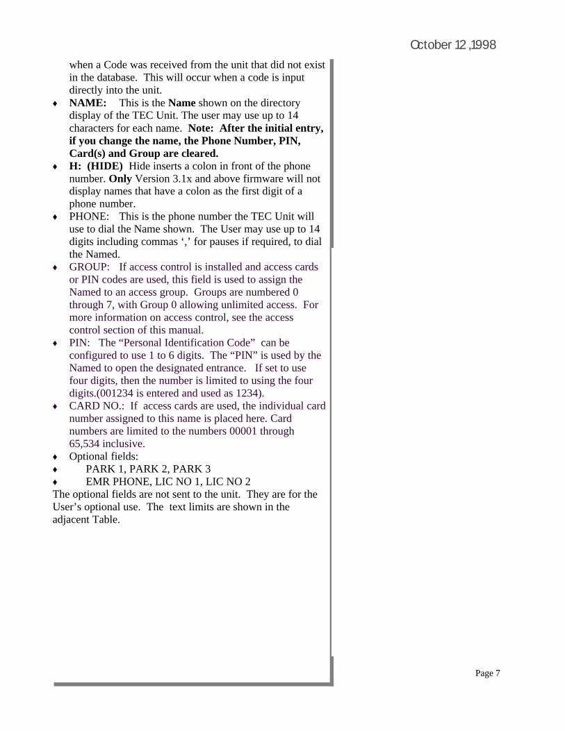
October 12 ,1998 when a Code was received from the unit that did not exist
in the database. This will occur when a code is input directly into the unit.
♦ NAME: This is the Name shown on the directory display of the TEC Unit. The user may use up to 14 characters for each name. Note: After the initial entry, if you change the name, the Phone Number, PIN, Card(s) and Group are cleared.
♦ H: (HIDE) Hide inserts a colon in front of the phone number. Only Version 3.1x and above firmware will not display names that have a colon as the first digit of a phone number.
♦ PHONE: This is the phone number the TEC Unit will use to dial the Name shown. The User may use up to 14 digits including commas ‘,’ for pauses if required, to dial the Named.
♦ GROUP: If access control is installed and access cards or PIN codes are used, this field is used to assign the Named to an access group. Groups are numbered 0 through 7, with Group 0 allowing unlimited access. For more information on access control, see the access control section of this manual.
♦ PIN: The “Personal Identification Code” can be configured to use 1 to 6 digits. The “PIN” is used by the Named to open the designated entrance. If set to use four digits, then the number is limited to using the four digits.(001234 is entered and used as 1234).
♦ CARD NO.: If access cards are used, the individual card number assigned to this name is placed here. Card numbers are limited to the numbers 00001 through 65,534 inclusive.
♦ Optional fields: ♦ PARK 1, PARK 2, PARK 3 ♦ EMR PHONE, LIC NO 1, LIC NO 2 The optional fields are not sent to the unit. They are for the User’s optional use. The text limits are shown in the adjacent Table.

Page 8
Version 1.32 Entering New Items into the Directory
Step by step Instructions to enter new items
Selcom 2000 provides a simple screen to enter new data into the directory. (See Pages 31 to 36 for handy work sheets to assist the user in entering the directory.) 1 On the Main Screen, Select or “Click” the
PROPER UNIT to enter the new items. 2 On the Main Screen, Select or “Click” the
Directory command button. The directory view screen will appear.
3 On the Directory screen, Select or “Click” the Add New Name command button. The screen will change to the Edit / Add view. All of the entries will be blank.
4 Start the entry by entering the Code Number. If you are using three digit code numbers(for example), you only need to enter the three digits and press the[Tab] key or press [Enter].
5 If the code has been already used, the screen automatically displays the record and changes to edit mode. You may change any and all items in this record, except the code number and the name. When you send updates, this record would be changed, except the code number.
6 If the code has not been used, the screen automatically steps or moves to the name field for entry. Enter the name before you exit this window as once entered, the name may not be changed! You may use the [Tab] or [Enter] key to move through the windows and enter the information you require. Only the code number is required in any record. All other fields are optional. When you send updates, this record will be added.
7 When all necessary fields are filled, Select or “Click” the Update Record(save it) command button. The record is saved.
8 Select or “Click” the Add command button to continue entering more data.
9 The information bars update to indicate the amounts of Unit memory used.
10 To enter more items Go to step 4.
Code Number
1 to 6 Digits
Name up to 14 Char’s
Phone up to 14 Digits
PIN 1 to 6 Digits
Card No. 5 Digits 1 to 65,534
Group 1 to 15 , 0 = unlimited
Directory Limits
Directory Limits
CAT Multi Door Directory in spreadsheet view
CAT Multi Door Directory in edit record view

Page 9
October 12 ,1998
PARK 1 9 Characters
PARK 2 9 Characters
PARK 3 9 Characters
EMR PHONE 14 Characters
LIC NO 1 10 Characters
LIC NO 2 10 Characters
Optional Field Capacities
Optional Fields Directory Limits
Unit Directory in Print Select Mode
Unit Directory in Print Preview Mode
Printing the Directory
The “Print View” Button will print the information showing on the screen using your default printer. When printing a small amount of information, the “Print View” Button may be used. Sorting by the chosen method (Sorting by Cards as an example) then using the elevators to display the desired numbers and Press “Print View” Button. On screens larger than 640 x 480, the panel may be expanded to show more information. This will print, to the limit of the printer. The information displayed will be printed on your default printer. In order to print to another printer, you must change your default printer to the one desired before using Selcom 2000. Choosing the ‘Select Print’ button allows the user to select the individual columns of the directory to be included in the printing. If too many columns are chosen the remainder will not be printed. Note: The column selection screen indicates the number of items to be printed and the number of pages that will be used. The sorting chosen for the display screen is also used for the printing. The “Temp to Directory” button allows you to return to the directory and change your sort and then return without losing your selections. You may return as many times as necessary to formulate your report. The individual column widths are adjustable by the user. While in the ‘Preview Print ‘ screen move your mouse pointer to the right edge of a column and when it changes shape, press the left mouse button and change width to the desired position. When satisfied with the look of your report, press ‘Print” and Selcom 2000 will use your default printer to print the report. Note: Select Print prints the directory twenty five lines to the page.

Page 10
Version 1.32
Showing Factory Defaults for the System Data
Unit System Configuration Standard
TEC II 2 lines of 16 characters
TEC IV 2 lines of 16 characters
TEC VIII & AVANTEC
1 line of 32 characters
TEC-VISION
6 lines of 16 characters
Title Page Message Table
Showing the sample TEC VIII & Avantec text
Unit System Configuration TEC VIII
Showing the sample vision text
Unit System Configuration TEC Vision
Unit System Parameters
Selcom 95 places all System Configuration Parameters on one screen. Complete descriptions of each item is available by placing the mouse pointer over each item. The standard factory defaults are provided as a reference. The defaults will be satisfactory in most applications. You may change them to provide for new password or directory description for example. A Telephone code is installed to open the first entrance. You may wish to change this and the Open and Latch tone for each of the entrances. ⇒ Directory On - Off - Turns the display of the Directory
On or Off. This does not prevent calling the numbers.
⇒ Keypad active - Allows the keypad to be used after
calling allowing for voice mail, etc. Only the numbers 0
to 9 are active, The * and # are not active.
⇒ Dial Touch Tone - Changes TEC Unit dialing from
touch tone to rotary or pulse dialing.
⇒ Back Beep - Sends a ‘Beep’ tone every ten seconds to
the called party. This allows confirmation that the call
originates from the TEC Unit.
⇒ Terminal Type - The TEC Unit normally sends data to
VT 100, however it can be change to output plain ASCII
if desired.
⇒ RS232 Baud Select - The serial port baud rate can be
configured from 300 to 9600 baud. If connected to a
printer, the baud rate should match the setting on the
printer. Range is 300 - 9600 Default is 9600
⇒ Answer Ring Count - This is the number of rings
received before the TEC Unit answers. Range is 0 - 9
Zero means the TEC Unit will not answer. 3 is the
default
⇒ Access Groups Enabled - On - Off If you set this to
off, All cards and PIN’s are ENABLED at ALL times.
⇒ Title Page Text - See Title Page Table
PRESS # TO VIEW DIRECTORY is the factory default.
⇒ Programming Password - This is the password used to

Page 11
October 12 ,1998
Item Range Default
Directory On-Off
On - Off On
Keypad Active
On - Off Off
Dial touch-tone
On - Off On
Back Beep On - Off Off
Terminal Type VT100 On Off
On - Off On - VT100
RS232 Baud Select
300 - 9600
1200
Answer Ring Count
0 (Off) - 9 3
Access Groups Enabled
On - Off
Title Page Text
See Title Page Table
PRESS # TO VIEW DIRECTORY
Programming Password
000000 to 999999 Letters are allowed
777777
Control Password
00 to 99 00 or 1st two digits of password
Directory Code Length
1 to 6 3
PIN Code 0 (Off) to 4
Site Code 000 to 000 = Off
Speaker - Mike Open
0 to 9 0
Talk Time 1 to 99 1
Alarm Time 0 to 99 00
System Configuration Table access and program the TEC Unit. Any combination
of up to six numbers and letters are allowed. 777777
is the default. Caution: Passwords with letters
cannot be accessed from the keypad or remote touch-
tone control.
⇒ Control Password -The control password is used to
dial the TEC Unit from a touch-tone phone and open
or latch an entrance. Range is 00 to 99 The default
is 00 or the 1st two digits of the password in Version
3.1x or higher firmware. See caution above. ⇒ Directory Code Length - Sets the displayed code
length from 1 to 6 characters. Set this parameter to
the number of digits you wish to be displayed and
dialed.
⇒ PIN Code Length - This sets the number of
characters used when you use ‘Personal
Identification Codes’ to allow entry. 0 (Off) or 1
to 6 numbers. 4 is the default.
⇒ Site Code - Site codes are used with cards. Set to
000 when not using cards or to the number provided
by SES when using cards. The range is 000 to 254 .
⇒ Speaker - Mike Open tone - This tone allows you
to turn the TEC Unit microphone on from a touch
tone phone and listen to the activity. Range is 0 to 9
Default is 0 (Off)
⇒ Talk Time - Talk time controls the amount of time
the TEC Unit stays connected to the called number
before automatically hanging up. Range is 1 to 99
Min. Default is 1 min. The TEC Unit beeps @ 10
seconds remaining as a warning.
⇒ Alarm Time - Alarm time controls the amount of
time the alarm relay remains active for an alarm
condition. Range is 1 to 99 sec. (0) reconfigures the
option board to become a third entrance control
unless the 4 reader option board is installed.
Page 12
Version 1.32
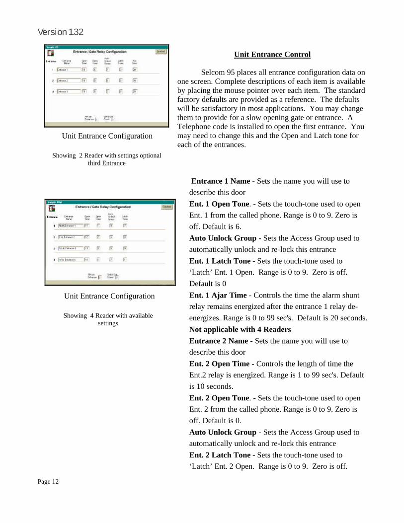
Unit Entrance Control Selcom 95 places all entrance configuration data on one screen. Complete descriptions of each item is available by placing the mouse pointer over each item. The standard factory defaults are provided as a reference. The defaults will be satisfactory in most applications. You may change them to provide for a slow opening gate or entrance. A Telephone code is installed to open the first entrance. You may need to change this and the Open and Latch tone for each of the entrances.
⇒ Entrance 1 Name - Sets the name you will use to
describe this door
⇒ Ent. 1 Open Tone. - Sets the touch-tone used to open
Ent. 1 from the called phone. Range is 0 to 9. Zero is
off. Default is 6.
⇒ Auto Unlock Group - Sets the Access Group used to
automatically unlock and re-lock this entrance
⇒ Ent. 1 Latch Tone - Sets the touch-tone used to
‘Latch’ Ent. 1 Open. Range is 0 to 9. Zero is off.
Default is 0
⇒ Ent. 1 Ajar Time - Controls the time the alarm shunt
relay remains energized after the entrance 1 relay de-
energizes. Range is 0 to 99 sec's. Default is 20 seconds.
Not applicable with 4 Readers ⇒ Entrance 2 Name - Sets the name you will use to
describe this door
⇒ Ent. 2 Open Time - Controls the length of time the
Ent.2 relay is energized. Range is 1 to 99 sec's. Default
is 10 seconds.
⇒ Ent. 2 Open Tone. - Sets the touch-tone used to open
Ent. 2 from the called phone. Range is 0 to 9. Zero is
off. Default is 0.
⇒ Auto Unlock Group - Sets the Access Group used to
automatically unlock and re-lock this entrance
⇒ Ent. 2 Latch Tone - Sets the touch-tone used to
‘Latch’ Ent. 2 Open. Range is 0 to 9. Zero is off.
Showing 2 Reader with settings optional third Entrance
Unit Entrance Configuration
Showing 4 Reader with available settings
Unit Entrance Configuration

Page 13
October 12 ,1998 Default is 0.
⇒ Ent. 2 Ajar Time - Controls the time the alarm
shunt relay remains energized after the entrance 2
relay de-energizes. Range is 0 to 99 sec's. Default
is 20 seconds. Not applicable with 4 Readers ⇒ Entrance 3 Name - Sets the name you will use to
describe this door
⇒ Ent. 3 Open Time - Controls the length of time the
Ent.3 relay is energized. Range is 1 to 99 sec's.
Default is 10 seconds.
⇒ Ent. 3 Open Tone. - Sets the touch-tone used to
open Ent. 3 from the called phone. Range is 0 to 9.
Zero is off. Default is 0.
⇒ Auto Unlock Group - Sets the Access Group used
to automatically unlock and re-lock this entrance
⇒ Ent. 3 Latch Tone - Sets the touch-tone used to
‘Latch’ Ent. 3 Open. Range is 0 to 9. Zero is off.
Default is 0.
⇒ Ent. 3 Ajar Time - Entrance 3 Ajar time is not
adjustable as it is the same as Ent.2. Shown to
clarify timing. Not applicable with 4 Readers
⇒ Entrance 4 Name - Sets the name you will use to
describe this door
⇒ Ent. 4 Open Time - Controls the length of time the
Ent.2 relay is energized. Range is 1 to 99 sec's.
Default is 10 seconds.
⇒ Ent. 4 Open Tone. - Sets the touch-tone used to
open Ent. 2 from the called phone. Range is 0 to 9.
Zero is off. Default is 0.
⇒ Auto Unlock Group - Sets the Access Group used
to automatically unlock and re-lock this entrance
⇒ Ent.4 Latch Tone - Sets the touch-tone used to
‘Latch’ Ent. 2 Open. Range is 0 to 9. Zero is off.
Default is 0.
Item Range Default
Entrance 1 Name 21 Characters Entrance 1
Ent.1 Open Time 1 to 99 sec's 10 sec's
Ent. 1 Open Tone 0 to 9 0 is off 6
Ent.1 Latch Tone 0 to 9 0 is off 0
Auto Unlock Group 0 to 7 0 is off 0
Ent. 1 Ajar Time 0 to 99 sec's or not applicable
20 sec's
Entrance 2 Name 21 Characters Entrance 1
Ent.2 Open Time 1 to 99 sec's 10 sec's
Auto Unlock Group 0 to 7 0 is off 0
Ent. 2 Open Tone 0 to 9 0 is off 0
Ent.2 Latch Tone 0 to 9 0 is off 0
Ent. 2 Ajar Time 0 to 99 sec's or not applicable
20 sec's
Entrance 3 Name 21 Characters Entrance 1
Ent.3 Open Time 1 to 99 sec's 10 sec's
Auto Unlock Group 0 to 7 0 is off 0
Ent. 3 Open Tone 0 to 9 0 is off 0
Ent.3 Latch Tone 0 to 9 0 is off 0
Entrance 4 Name 21 Characters Entrance 1
Ent. 3 Ajar Time Same as Ent 2 Ajar time or not
not adjustable
Ent.4 Open Time 1 to 99 sec's 10 sec's
Auto Unlock Group 0 to 7 0 is off 0
Ent. 4 Open Tone 0 to 9 0 is off 0
Ent.4 Latch Tone 0 to 9 0 is off 0
Ent. 4 Ajar Time Not Applicable none
Entrance Configuration Table

Page 14
Version 1.32
Zone Start Time
Stop Time
Days Allowed
0 7:00 am
6:00 PM
Monday to Friday
1 6:00 am
6:00 PM
Monday to Friday
2 6:00 am
6:00 PM
Saturday, Sunday, Holidays
3 10:40 PM
11:59 PM
Monday to Friday
4 12:00 am
7:20 am
Monday to Friday
5 8:40 am
5:20 PM
Monday to Friday
6 7:45 am
8:15 am
Monday to Friday
7 4:45 PM
5:15 PM
Monday to Friday
Sample 49 Time Zone Configuration Table
Two Reader Access Screen
Four Reader Access Screen
Unit Access Control
Selcom 95 places all Access Control data on one screen. Complete descriptions of each item is available by placing the mouse pointer over each item. The Sample 49 settings supplied are provided as a reference in the illistrations and will be used to explain the uses. Note the second screen showing similar settings on a four reader system. The descriptions include Entrance four where applicable.
Time Zones Times Zones allow the User to set up 8 different time slots. Each Time Zone is a separate continuous time slot. The sample zones are configured as shown on the Time Zone table. Zone 0 shows a time zone starting at 7 am to 6 pm Monday through Friday. This would be typical of a factory building open times.Time Slots must end at midnight. To set up a Group that has access through midnight, you must use two Time Zones as shown in the example as Time Zone 3 and Time Zone 4. The days of the week may be chosen for each Time Zone by ‘Clicking’ each day you wish to use. ‘Clicking the box again removes the selection. The Holidays box will allow access on the nine dates entered on the form. Time Zone One allows access from 6 am through 6 pm, Monday through Friday. Time Zone Two allows access from 6 am through 6 pm, Saturday, Sunday and Holidays. Time Zone Six allows access from 7:45 am through 8:15 am, Monday through Friday. and Time Zone Seven allows access from 4:45 pm through 5:15 pm, Monday through Friday. This could be typical of busy times at a Gate entrance and exit.

Page 15
October 12 ,1998
Level Time Zone Used
Entrances Affected
0 0 Entrance One, Two,Three and Four
1 1 Entrance One, Two,Three and Four
2 2 Entrance One, Two,Three and Four
3 3 Entrance One, Two,Three and Four
4 4 Entrance One, Two,Three and Four
5 5 Entrance Two and Four
6 6 Entrance One and Three
7 7 Entrance One and Three
Sample 49 Access Level Table
Access Group Access levels and Zones Used
Zero (0) None - predefined as unlimited access
One (1) Level Zero using time zone zero with all entrances 7:00 am through 6:00 PM Mon. - Fri.
Two (2) Level One using time zone one with all entrances 6:00 am through 6:00 PM
Three (3) Level Two using time zone two with all entrances 6:00 am through 6:00 PM, Sat, Sun and Holidays.
Four (4) Levels Three and Four using time zones three and four combined to allow access through all entrances 10:40 PM through 7:20 am, Mon. - Fri.
Five (5) Level Five using time zone five with entrance two 8:40 PM through 5:20 PM
Six (6) None, not set to any
Seven (7) Levels Six and Seven with entrance one during 7:45 am through 8:15 am and then 4:45 PM through 5:15 PM Mon. - Fri.
Sample 49 Access Groups Table
Entrance Access Group
Access Level
Time Zone
One Seven Six and Seven
7:45 am to 8:15 am and 4:45 PM to 5:15 PM
Two None None None
Three Seven Six and 7:45 am to 8:15 am and
Four None None None
Sample 49 Auto Unlock / Re-lock Table
Access Levels Access Levels are used to attach Time Zones to specific Entrances. The Access Levels Zero through Four are assigned to all entrances. Access Level Five is assigned to Entrance Two and Four , uses Time Zone Five (8:40 am through 5:20 pm). Access Level Six is assigned to Entrance One and Three, uses Time Zone Six (7:45 am through 8:15 am). Access Level Seven is assigned to Entrance One and Three, uses Time Zone Seven (4:45 pm through 5:15 pm).
Access Groups
Access Groups are used to allow groups of individuals card or PIN access by assigning a level or combination of levels to their group. Access Group Zero is predefined as an unlimited group. Group Zero allows access 24 hours a day, ALL days of the year. Access Groups are assigned to the individuals in the Directory. If you do not assign a Group to an individual during the directory entry, Zero (0) is assigned by default. The examples provided show only a few ways to combine levels into a group to allow specific access to certain individuals. For example in Group Six, Access Levels Zero (0) and One (1) could be selected to allow a group to have access seven days a week, 7:00 am to 6:00 pm Mon. - Fri. and 6:00 am to 6:00 pm Sat, Sun and Holidays and using all entrances as selected.
Holidays
Up to Nine Holidays may be entered in a TEC Series with a clock and access control . They are entered as two digits for the month, a slash, and two digits for the day (XX/XX). If a Holiday is entered and falls on a Mon -Fri, any group set with a time zone of Mon - Fri without Holidays will not have access on the holiday. Further, any group using access levels with time zones without Holiday access will not have access on the Holiday.
Automatic Unlock and Re-lock
You may choose to automatically unlock (or open) and re-lock (or close) an entrance (or gate) using access groups. The example provided shows Access Group Seven used to open the Number One entrance once at 7:45 am to 8:15 am and again at 4:45 pm to 5:15 pm. This example might be an employee gate that automatically opens during the peak traffic flow. Another example would be to use Group Five using Level Five and Time Zone Five to keep open the Second Entrance during normal business hours.

Page 16
Version 1.32
Unit Event Log Control Selcom 95 provides for formatting and viewing of the Event Log Buffer information and maintaining a single, separate log file for each unit. Sorting and filtering of the Log Events are available and do not alter the data in the log. You may use the Sorts & Filters to selectively display and print groups of records in the log. If your computer has a screen resolution higher than 640 x 480, you may resize the Window up to the full size of your screen to display more data. ⇒ File size limited by the size of your computer storage
capacity, not by the software. ⇒ Default Sort is by date and time ⇒ Sorting is allowed on any column ⇒ Temporary sizing of any column is allowed ⇒ Selections and sorting do not change the real data ⇒ Log columns separated into logical types to enhance
sorting and selecting ⇒ All data is provided, including partial messages that
result from data wrap in the buffer. ⇒ Automatic update mode prevents most data repetition. ⇒ Erase to date allows maintaining your log at the size
and dates you desire. Open File add function allows you to add old logs to the file if desired.
Log View with columns adjusted, Date & Time Sort and Row Highlight selected.
Data Columns may be temporarily adjusted by dragging the column edge and
sorted by clicking the column Title
Code Directory Code of Event, if applicable
Name Directory Code of Event, if applicable
Card Directory Code of Event, if applicable
PIN Directory Code of Event, if applicable
Activity Description of event
Message Message about event
Date Date event occurred
Time Time event occurred
Other 1 Partial messages, as in Log wraparound
Other 2 Partial messages, as in Log wraparound
Log Information Provided
Log Utility with record showing
Open File Opens old file for conversion
Get Data Loads file chosen with Open file
Erase Log COMPLETELY Erases Log
Erase to Date
Erases Log BEFORE a selected Date
|< < > >| Data
Control Bar
Allows movement through Log and view individual records.
Log Utility Function Table

Page 17
October 12 ,1998
Sample Converted Log Code Name Card Pin Activity Message Date Time Other 1 Other 2
ENTRANCE 2 LOCKED 09/30/97 13:36
DOOR 2 FORCED 09/30/97 13:37
REX ENTRANCE 2 09/30/97 13:37
ENTRANCE 2 LOCKED 09/30/97 13:37
CODE 167 DEPLAZA CARD 02106 ENTRANCE 1 09/30/97 13:37
ENTRANCE 1 LOCKED 09/30/97 13:38
CODE 098 TEST ENTRY PIN 1234 ENTRANCE 1 OPEN 09/30/97 13:38
ENTRANCE 1 LOCKED 09/30/97 13:38
CODE 432 MATA, MARIO & DIALED 09/30/97 13:38
CALLER HUNGUP 09/30/97 13:38
CODE 255 TEST 2 PIN 4321 ENTRANCE 1 OPEN 09/30/97 13:39
ENTRANCE 1 LOCKED 09/30/97 13:39
INVALID PIN 0300 ATTEMPTED ENTRANCE 1
09/30/97 13:39
Sample Direct Log
ENTRANCE 2 LOCKED 13:37 09/30/97 CARD 02106 CODE 167 DEPLAZA ENTRANCE 1 OPEN 13:37 09/30/97 ENTRANCE 1 LOCKED 13:38 09/30/97 PIN 1234 CODE 098 TEST ENTRY ENTRANCE 1 OPEN 13:38 09/30/97 ENTRANCE 1 LOCKED 13:38 09/30/97 CODE 432 MATA, MARIO & DIALED 13:38 09/30/97 CALLER HUNGUP 13:38 09/30/97
Printing the Transaction Log Choosing the ‘Select Print’ button allows the user to select the individual columns of the log to be included in the printing. If too many columns are chosen, the remainder will not be printed. The sorting chosen for the display screen is also used for the printing. The individual column widths are adjustable by the user. While in the ‘Print Preview ‘ screen, move your mouse pointer to the right edge of a column and when it changes shape, press the left mouse button and drag the width to the desired position. When satisfied with the look of your report, press ‘Print” and Selcom_95 will use your default printer to print the report.

Page 18
Version 1.32
Add TEC Unit Wizard Selcom 95 provides a ‘Wizard’ to help with the installation of a new Unit. It provides a step by step method of providing the information required and desired. You will need the following information at hand to ‘setup’ a new unit in the software ⇒ Your Name for the Unit ⇒ Unit Address (optional) ⇒ Unit City (optional) ⇒ Unit Model ⇒ Unit Phone Capacity ⇒ Unit Card Capacity (If Used) ⇒ Unit Card reader Type (SES standard is W-30) ⇒ Unit Phone Number ⇒ Method of Dialing - Use a 1 prefix or not ⇒ You must have a modem installed into Windows 95 if
you will be using that to communicate to the Unit. If a modem is properly installed, you will be able to merely SELECT it in a pull down selector box. If not, you may select it later using the Edit Unit Data selection from the File menu .
Using the Wizard The Wizard takes you step by step through the information
required, providing default answers when applicable. You may go back to correct any item without reentering the remaining data you previously entered. A review is provided at the finish, allowing you to view all the entries at one time. If something needs to be changed, use the ‘Previous’ button to go back and correct the entry. When you have completed the entries, the ‘Finish’ button will enable and when pressed, sets up the new unit for you.

Page 19
October 12 ,1998
Edit Unit Data Selcom 95 places Unit Data configuration data on one screen. Complete descriptions of each item is available by placing the mouse pointer over each item. The Wizard is the standard method used to complete this form . The Wizard also generate the data files needed to store the information for each new site. This screen is provided to allow changes to be entered when required. ⇒ Unit Name - contains the file name for the unit ⇒ Site Description - contains the Unit’s name you refer to ⇒ Street Address - for your reference ⇒ City - for your reference ⇒ Unit Phone - insert the number to be called including
any prefixes required. (Example - 9,1028812125551212). Up to 32 digits may be used to dial the number used by Selcom 95 to connect to the unit
⇒ TEC Unit Model No. - select from list ⇒ Code Capacity - Code or Card capacity you purchased ⇒ Phone Capacity - Phone Capacity you purchased ⇒ Use Modem / Use Direct Connect - how will you connect to the unit to Put data and Get data. ⇒ Modem Name - Pull down select for finding the modem in your computer. ⇒ Baud Rate - Current modems available from SES are 1200 baud (most prevalent) and 9600
baud. Both modems operate at 1200 baud, you may safely set to this default. ⇒ Maximum Backups - This sets the number of previous sessions the software stores. Once this
number is reached, the backups are automatically rotated, replacing the oldest first. Default is nine and is recommended.
⇒ Next Backup No - shows the position of the current backup. ⇒ Has Big Buffer - Set if Big Buffer is installed in Unit. Will only show if function is available. ⇒ Erase Buffer on Receive - Sets program to erase buffer when data has been received. ⇒ Multi Unit - Sets software to allow for multiple units on a single phone line and sets sleep mode
active for multiple units on single phone lines. ⇒ No.of Units on MUI - Sets software to the number of units connected on ONE phone line. ⇒ Firmware version - automatically uploads this information from the unit to reconfigure software
for new units. Options -Screen
⇒ Cards Readers - preset the screens to the proper version and number of readers. ⇒ Vision Display Parameters - allows setting of the TEC Vision display. This includes the size of
the characters, number of displayed columns, name or calling code first,display an instruction page and automatically scroll the names on the display. This feature requires firmware Version 3.1X or higher to function.

Page 20
Version 1.32
Error Control
Selcom 95 uses the standard TAPI interface within Windows 95. This allows for a modem to be installed into Windows 95 and Selcom 95 will use it. Selcom 95 requires that error control be turned off. We are providing the following instructions to turn off error control. In order to assist you we have provided the following setup.
Using Start - select ‘Settings’ then ‘Control Panel’ then,if required , ‘Control Panel’.
Setting your Microsoft Windows Telephone Application Programming Interface
( TAPI )
Long Distance Control Under some conditions Windows 95 TAPI controls do not handle dialing and or long distance correctly. For your convenience, the local area code awareness of Windows 95 is not used. This means you will control the long distance area codes. In Selcom 95, enter (area prefix suffix) in the Wizard or in ‘Edit TEC Unit Data Screen. Place the correct number in the Unit Phone: window. Example : ‘3055551212’. Place any special prefix and all the numbers necessary and Selcom 95 TAPI will dial it exactly for you. This feature allows for 10 digit local calling, same area code long distance calling as well as special carrier long distance calling as in (1028813975551212). Selcom 95 allows for 32 digits to be placed into the called number. Spaces, Parentheses and Dashes are not required and not allowed.

Page 21
October 12 ,1998 Setting your Microsoft Windows Telephone Application
Programming Interface ( TAPI )
continued...
Using Control Panel - select ‘Modems’.
Then select the modem you will use with Selcom 95. Next select the ‘Properties’ menu.
Using ‘Properties, select Advanced and then ‘Connections’.
Using ‘Advanced Connection Settings, make sure ‘Use error control’ is NOT checked. Then click ‘OK’ and then ‘OK’ again.
Page 22
Version 1.32
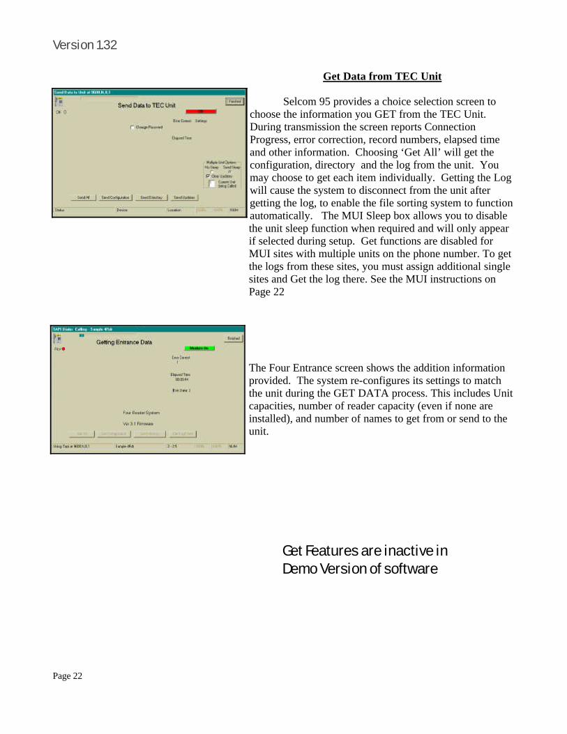
Get Data from TEC Unit
Selcom 95 provides a choice selection screen to choose the information you GET from the TEC Unit. During transmission the screen reports Connection Progress, error correction, record numbers, elapsed time and other information. Choosing ‘Get All’ will get the configuration, directory and the log from the unit. You may choose to get each item individually. Getting the Log will cause the system to disconnect from the unit after getting the log, to enable the file sorting system to function automatically. The MUI Sleep box allows you to disable the unit sleep function when required and will only appear if selected during setup. Get functions are disabled for MUI sites with multiple units on the phone number. To get the logs from these sites, you must assign additional single sites and Get the log there. See the MUI instructions on Page 22 The Four Entrance screen shows the addition information provided. The system re-configures its settings to match the unit during the GET DATA process. This includes Unit capacities, number of reader capacity (even if none are installed), and number of names to get from or send to the unit.
Get Features are inactive in Demo Version of software

Page 23
October 12 ,1998
Send Data to TEC Unit
Selcom 95 provides a choice selection screen to choose the information you SEND to the TEC Unit. During transmission the screen reports Connection Progress, error correction, record numbers, elapsed time and other information. The system re-configures its settings to match the unit during the SEND DATA process. Choosing ‘Send All’ will send the Unit configuration and ALL of the directory data to the unit. You may choose to send each item individually. Sending Updates will cause the system to send new and changed directory items only, then disconnect, providing for a shorter connection time. You also have the option of changing the Unit password as you send the configuration to the Unit. After completing the change, the system enters the new password into the file automatically. The Mulitple Unit Function area allows the operator to disable the unit clear updates, disable the sleep function when required and will only appear if MUI functions are selected during setup. See Page 24 for more detail.
Send Features are inactive in Demo Version of software
Page 24
Version 1.32
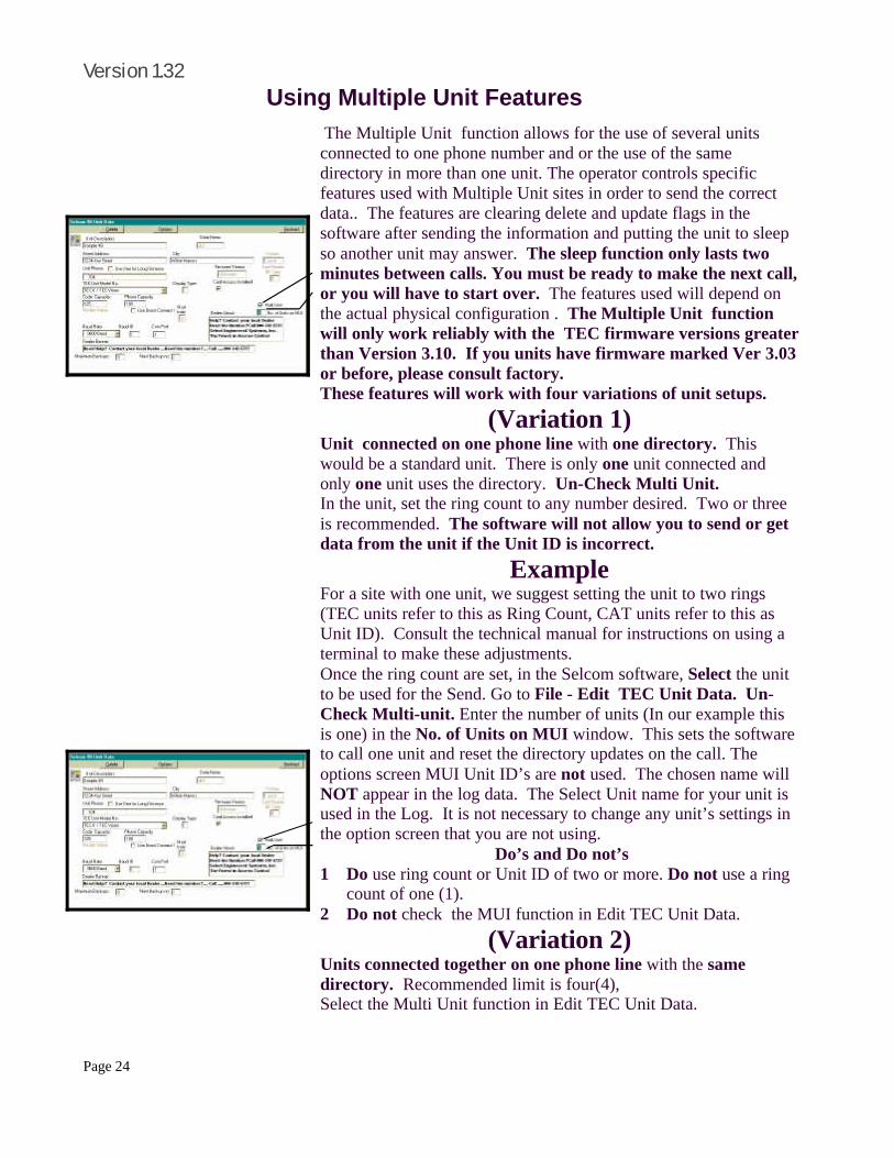
The Multiple Unit function allows for the use of several units connected to one phone number and or the use of the same directory in more than one unit. The operator controls specific features used with Multiple Unit sites in order to send the correct data.. The features are clearing delete and update flags in the software after sending the information and putting the unit to sleep so another unit may answer. The sleep function only lasts two minutes between calls. You must be ready to make the next call, or you will have to start over. The features used will depend on the actual physical configuration . The Multiple Unit function will only work reliably with the TEC firmware versions greater than Version 3.10. If you units have firmware marked Ver 3.03 or before, please consult factory. These features will work with four variations of unit setups.
(Variation 1) Unit connected on one phone line with one directory. This would be a standard unit. There is only one unit connected and only one unit uses the directory. Un-Check Multi Unit. In the unit, set the ring count to any number desired. Two or three is recommended. The software will not allow you to send or get data from the unit if the Unit ID is incorrect.
Example For a site with one unit, we suggest setting the unit to two rings (TEC units refer to this as Ring Count, CAT units refer to this as Unit ID). Consult the technical manual for instructions on using a terminal to make these adjustments. Once the ring count are set, in the Selcom software, Select the unit to be used for the Send. Go to File - Edit TEC Unit Data. Un-Check Multi-unit. Enter the number of units (In our example this is one) in the No. of Units on MUI window. This sets the software to call one unit and reset the directory updates on the call. The options screen MUI Unit ID’s are not used. The chosen name will NOT appear in the log data. The Select Unit name for your unit is used in the Log. It is not necessary to change any unit’s settings in the option screen that you are not using.
Do’s and Do not’s 1 Do use ring count or Unit ID of two or more. Do not use a ring
count of one (1). 2 Do not check the MUI function in Edit TEC Unit Data.
(Variation 2) Units connected together on one phone line with the same directory. Recommended limit is four(4), Select the Multi Unit function in Edit TEC Unit Data.
Using Multiple Unit Features

Page 25
October 12 ,1998
Using Multiple Unit Features
Indicate the number of units to send the same directory or updates to (2,3 or 4). In each unit, set the separate ring counts. Consult the technical manual for instructions on using a terminal to make these adjustments.
Example For a site with three units, we suggest setting one unit to two rings, the second unit to four rings and the last unit to six rings (TEC units refer to this as Ring Count, CAT units refer to this as Unit ID). Consult the technical manual for instructions on using a terminal to make these adjustments. Once the ring counts are set, in the Selcom software, Select the unit to be used for the Send. Go to File - Edit TEC Unit Data. Check Multi-unit. Enter the number of units (In our example this is three) in the No. of Units on MUI window. This sets the software to call three units and reset the directory updates on the third call. Go to the options screen and set the MUI Unit ID’s to match your unit settings. Set the top selection to match your first unit (the unit with the lowest ring count or unit id.) and your second unit next with your third unit next. You may rename each unit, if you wish and your chosen name will appear in the log data. It is not necessary to change any additional unit’s settings in the option screen that you are not using. The software will not allow you to send or get data from the unit if the Unit ID is incorrect. When the site is called, system will call the first of the units indicated in the Edit TEC Unit Data Screen one at a time. If you are sending All or the directory or directory updates, a special sequence is followed: 1 The first (the one with the lowest ring count) unit is called first.
The ID of the unit is checked to insure the proper unit answered. 2 This unit (and each following) will be put to sleep at the end of
each transmittal to allow the next unit to answer. The update flag is not cleared for directory updates until the last unit is sent or if the clear updates box is checked.
3 A Count-Down window is visible on the Main Screen showing the units remaining to be called.
4 Repeat the Send command for each unit. Only the first button selected is allowed on subsequent calls. After the last unit is finished, the software will return to the main screen To obtain the Log information from units, create separate MUI Identification names in the option screen (See page 20) using different names for each unit . This MUI Identification will be placed in the log. When getting the logs from MUI sites, the auto skip date feature is blocked. If the log is not deleted in the software before the Get,
Options screen showing MUI Identifications

Page 26
Version 1.32 or in the units after the Get, data will be repeated. If you desire to check the contents of the individual directories, it is recommended to used variation 2 to check the contents as a single directory will not show you any differences.
Do’s and Do not’s 1 Do keep ring counts separated by two (2,4,6,8). CAT Multi Door Systems may be set one count
apart depending on conditions. 2 Do not use a ring count of one (1) on any unit except a CAT Unit. 3 Do keep a list of the order of units to call. 4 Do not wait more than 1½ minutes between calls as the sleep function in the units will end.
Selcom 2000 will stop and give you a message if the Unit Id does not match the expected number.
(Variation 3) Units connected together on one phone line with the different directories (using different unit names for each unit). Recommended limit is four(4). Create separate sites for each of the units. Label each unit clearly (perhaps by location?) Select Multi Unit on each of the units. Indicate the number of units to send as Two (2) on all of the units. Use a different Unit ID (or Ring Count) for each of the units.
Example When the site is called, system will set to call the number of units indicated in the Edit CAT / TEC Unit Data Screen. that is why it is important to set each site to one. This will tell the software to clear updates, but put the unit to sleep. If you are sending All or the directory or directory updates, a special sequence is followed: 1 The first (the one with the lowest ID) unit is called first. 2 This unit (and each following) will be put to sleep at the end of each transmittal to allow the next
unit to answer. The update flag is cleared for directory updates when the number of units on MUI is set to one. This is automatically set when the current unit becomes the last to send to.
3 Select each unit in turn and repeat the Send command for each unit. 4 Getting all information from the units is allowed as the files used are separate. To obtain the
information from units, select each unit in turn and perform the upload or download function desired.
5 The system will automatically put each unit to sleep unless the No Sleep selection is made. Do’s and Do not’s
1 Do keep ring counts separated by two (2,4,6,8). 2 Do keep a list of the order of units to call. 3 Do not wait more than 1½ minutes between calls as the sleep function in the units will end.
Selcom 2000 will stop and give you a message if the Unit ID does not match the expected number.

Page 27
October 12 ,1998 (Variation 4) Units connected on different phone lines with the same directory. There is no recommended limit, but care must be taken to insure all units are updated with new data. In each unit, select Multi Unit. Indicate the number of units to send the same directory or updates to (2). In each unit, set each unit’s ring count or Unit ID to the same setting.
Example For a site like this, we suggest setting to two rings, (TEC units refer to this as Ring Count, CAT units refer to this as Unit ID). Consult the technical manual for instructions on using a terminal to make these adjustments. Once the ring counts or Unit ID’s are set, in the Selcom software, Select the unit to be used for the Send. Go to File - Edit CAT / TEC Unit Data. Check Multi-unit. Enter the number of units (In our example as well as any site of this type, this is two) in the No. of Units on MUI window. Note the file name in Data Name Window. This sets the software to call two units and reset the directory updates on the second call. Go to the options screen and set the MUI Unit ID’s to match your unit settings ( in this case all units to 2). Set the top selection to match all units (the unit with the lowest ring count or unit id.). Using the Add Unit Wizard, set up each of the additional units including the proper phone number. Set each unit to a MUI site and number of units to 2. Enter the file name in the Data Name Window from the first Unit. This will make this unit use the first units directory. When each site is called, system will call the indicated unit in the Edit CAT / TEC Unit Data Screen one at a time using the Directory file entered in the Edit CAT/TEC Unit data screen. If you are sending All or the directory or directory updates, a special sequence is followed: 1 On the Main Screen select the first unit. The first (the primary) unit is called first. The ID of the
unit is checked to insure the proper unit answered. Note: All units Must have the same ID. 2 This unit (and each following) will be sent the same directory. The update flag is not cleared for
directory updates until the clear updates box is checked. This Flag allows you to send just the updates to the units to save time. You may send Directory when you wish to make sure ALL data is in the unit.
3 After the call is completed, abort the second call, and go to the Main Screen and Select the second unit. Each time you Select anther unit to give the same directory to, repeat the Send command for each unit. When you send to the final unit you may select No Sleep as this will clear the update flags in the directory file on the last call. To obtain the configuration and log information from units, create more separate units (See page 20) using different names for each unit . These names will be placed in each individual log. If you desire to check the contents of the individual directories, it is recommended to used these separate files to check the contents as a single directory may not show you any differences. If you are concerned that the individual units do not have the same information, sending the complete directory erases the units contents and replaces it with the computer file you send.
Do’s and Do not’s 1 Do use the same ring count 2 Do not use a ring count of one (1). 3 Do keep a list of the order and names of units to call. 4 Do check MUI and set number of units on directory to 2.

Page 28
Version 1.32
Helpful Hints Selcom 95 is designed to use the SMALL(Normal Size) font selection in the Control Panel - Display - Settings - Font Size. Choosing Large fonts will cause some wording not to be displayed.
General The [TAB] key and [Shift Tab] key also moves from text window to text window. The [Enter] key behaves like the [TAB] key as well. The minimum machine specified will operate correctly when only Selcom 95 is running. Other programs must be exited first.
Data Files Data files and the backups are compatible with Microsoft Access Version 7.0 or higher and may be used to generate reports from the data if desired.
Remote Data Storage if you wish to store your data and/or backup data in another location, copy the files in your Selcom 95 directory. If you did a standard install, the files are in C:\Program Files\Selcom 95\*.mdb . The backup files are in C:\Program Files\Selcom 95\Backup\*.md* . Copy these files to a location of your choice.
Version
When talking to tech support, your serial number and the version number(shown on the Help - About menu selection) is very important.
Directory Refresh retrieves a new copy from the disk and resets the records to the original order. Selecting a name to edit automatically sets the record to be sent to the unit on the next update. To print a partial Directory, sort by the type of request, then use the elevator bar to view what you want to print and press "Print View".
Edit Directory Return to view button updates the record Update Record Button is present to allow user to continue to enter new records as in Add New Button - complete the record - Update Record Button(save it) - Add New Button - etc... In the Directory EDIT screen the triangles located on the lower record bar allow you to move through the directory. The Left Bar-triangle moves to the first record, the triangle moves one record towards record one. The right triangle moves one record towards the last record and the Right Bar-triangle moves to the last record in the directory.
Helpful Hints and Short Cuts

Page 29
October 12 ,1998
Entering New Items into the Directory Step by step Instructions to enter new items
Selcom 95 provides a simple screen to enter new data into the directory. 1 On the Main Screen, Select or “Click” the
PROPER UNIT to enter the new items. 2 On the Main Screen, Select or “Click” the
Directory command button. The directory view screen will appear.
3 On the Directory screen, Select or “Click” the Add New Name command button. The screen will change to the Edit / Add view. All of the entries will be blank.
4 Start the entry by entering the Code Number. If you are using three digit code numbers(for example), you only need to enter the three digits and press the[Tab] key or press [Enter].
5 If the code has been already used, the screen automatically displays the record and changes to edit mode. You may change any and all items in this record, except the code number. When you send updates, this record would be changed, except the code number.
6 If the code has not been used, the screen automatically steps or moves to the name field for entry. You may use the [Tab] or [Enter] key to move through the windows and enter the information you require. Only the code number is required in any record. All other fields are optional. When you send updates, this record will be added
7 When all necessary fields are filled, Select or “Click” the Update Record(save it) command button. The record is saved.
8 Select or “Click” the Add command button to continue entering more data.
9 The information bars updates to indicate the amounts of Unit memory used.
10 To enter more items Go to step 4.
Code Number
1 to 6 Digits
Name up to 14 Char’s
Phone up to 14 Digits
PIN 1 to 6 Digits
Card No. 5 Digits 1 to
Group 1 to 7 , 0 =
Directory Limits
Directory Limits

Page 30
Version 1.32
Access Control 12,13 Main Screen 4,5
Access Groups 13 Memory Requirements 2
Add New Names 6,22,23 Modem Setup 16,17,18
Add New TEC Unit 16 MUI Features 22,23
Authority Levels 5 Name, Entrance 10
Automatic unlocking entrances
13 Name, in directory 6,7,22,23
Clock Setting 30 Optional Fields 7
Code Numbers 6,9 Phone, in directory 6,7
Code Numbers 6,7 Print Directory 7
Dialing Setup 6,7,17,18 Print Transaction Log 15
Directory Title Change 8 Program Organization 5
Edit Directory 6,17,22,23 Program Setup 2,3
Edit TEC Unit Parameters 8,9 Ring Count 8
Entrance Names 10,11 Sample Data 4
Entrance Setup 10,11 Sending Unit Data 21
Erase Buffer 17,20 Setup Software 2
Error Control 18 Setup Wizard for TEC Unit 16
Getting Unit Data 20 Short Cuts 22
Hard Disk Space 2 Site Code 9
Help, Built in 4 Sleep MUI 17,22-23
Hints for Users 22,23 Time Zones 12
Hide, Names in directory 6,7 Tec Vision Settings 31
Holidays 13 Terminal Mode 30
Install Software 2 Unit System Parameters 8,9
Log Utility 14 Unlimited Access 13
Login Passwords 5 Worksheets, Directory 26,27
Long Distance Dialing 7,16,17,18 Worksheets, Unit Setup 25
Index
Page 31
October 12 ,1998
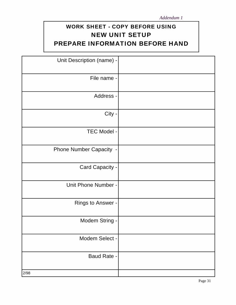
Unit Description (name) -
File name -
Address -
City -
TEC Model -
Phone Number Capacity -
Card Capacity -
Unit Phone Number -
Rings to Answer -
Modem String -
Modem Select -
Baud Rate -
2/98
WORK SHEET - COPY BEFORE USING NEW UNIT SETUP
PREPARE INFORMATION BEFORE HAND
Addendum 1

Page 32
Version 1.32 Addendum 2
CODE NUMBER
1 - 6 Numbers
NAME up to 14 Characters
PHONE NUMBER up to 14 Numbers
PIN NUMBER 1 to 6 Digits
CARD NUMBER 5 Digits,
1 to 65,534
GROUP NUMBER
1 to 7, 0 = unlimited
BEFORE WRITING - COPY THIS FORM USE THIS WORK SHEET TO ASSEMBLE YOUR DIRECTORY PART ONEPART ONE

Page 33
October 12 ,1998
PARK 1 9 Characters
PARK 2 9 Characters
PARK 3 9 Characters
EMERGENCY PHONE No. 14 Characters
LICENSE NUMBER 1
10 Characters
LICENSE NUMBER 2
10 Characters
Addendum 3
BEFORE WRITING - COPY THIS FORM USE THIS WORK SHEET TO ASSEMBLE YOUR DIRECTORY PART TWOPART TWO

Page 34
Version 1.32
NOTE: ONCE TIME/DATE PROGRAMMING HAS BEGUN, ALL SELECTIONS MUST BE COMPLETED FOR CHANGES TO TAKE EFFECT.
4.2.5.1 SETTING TIME / DATE
00:00 00/00/00 MIN.:
00:00 00/00/00 HOUR:
Select "1" to set the time & date. You will be prompted to enter the current time in minutes as a one or two digit number. If you make a mistake, press "←” to backspace one character. After the minutes are entered, press the "Enter" key. Enter a 1 or 2 digit number to set the hour. If a mistake is made, press "←” to backspace one character. After the hour is entered, press the "Enter" key. This is NOT the day of the month. This is a number which corresponds to the day of the week. Enter a number corresponding to the day of the week. Sunday is "1", Saturday is "7" and so forth. If you make a mistake, press " ←” to backspace one character. After the day of the week is entered, press the "Enter" key. Enter a 1 or 2 digit number to set the day of the month. If a mistake is made, press "←” to backspace one character. After the day is entered, press the "Enter" key.
00:00 00/00/00 DAY, 1..7:
00:00 00/00/00 DATE:
It is occasionally necessary to directly manipulate the contents of the Tec units’ memory. Using the Terminal selection from the Selcom 95 Options menu can do this. 1) Select the desired site. 2) Click on Options. 3) Click on Terminal. 4) Click on File, then Place Call or click on the telephone icon. Selcom 95 will call the Tec unit and prompt you for the password by changing the screen from white to black and prompting with the word PASSWORD: This is the programming password found in your System CFG menu. Key in the 6 digit password and press “Enter” You should get a selection that says Main Menu and has 9 selections available. These selections correspond to the sections in the Tec Manual that came with your Tec product. In the examples that follow, the section heading is referring to the manual section that describes the function. For example setting the clock time is something that would be required twice a year to go on (or off) daylight savings time.
How to get into Terminal Mode
EXCERPTS FROM TEC MANUALS FOR YOUR CONVENIENCE

Page 35
October 12 ,1998
00:00 00/00/00 YEAR:
00:00 00/00/00 MONTH:
LINES 2 - 6
LINE 1
Enter a 1 or 2 digit number to set the month. If you make a mistake, press " ←” to backspace one character. After the month is entered, press the "Enter" key. Enter a 2 digit number to set the year. If you make a mistake, press " ←” to backspace one character. After the year is entered, press the "Enter" key. You will be returned to the Clock Setup menu. 4.2.3.9 TEC VISION TITLE PAGE The Tec Vision Title Page has six lines of up to sixteen characters per line, including punctuation, when programmed from terminal mode. To program the Title Page, press "9" from the System Parameters menu to get this sub-menu. Key in the desired characters. Press " ←←” simultaneously to backspace one character. When the first line is complete, press "Enter" to advance to the second line. Continue the 2nd through 6th lines as required. If you require any modifications of any line, then line 1 must be re-entered, along with any of the other lines preceding the line you want to change. After completion, press "Enter". This will return you to the System Parameters menu. 4.2.4.6 TEC VISION LCD CONFIGURATION
This selection controls: A) How many columns are displayed. B) Which of three character sizes are displayed. C) Whether line spacing is single or double. D) Whether names scroll, and how fast. E) Whether code position is to the left or right of the name. F) Whether instructions are for handset or handsfree models, or ignored. Character size 1 is the smallest character size TecVision supports. Character size 2 is twice as big as character size 1, and character size 4 is four times as big. 1, 2, and 4 are the only choices.
NUM OF COL <1 - 3> CHARSIZE <1, 2, 4> S/D SPACE <1 - 2> AUTO SCROLL <0 - 9> CODE POS. <0 - 1> INST. TYPE <0 - 2>

Page 36
Version 1.32

Page 37
October 12 ,1998
“BETTER TECHNOLOGY MAKES BETTER SYSTEMS”
10/98
Select Engineered Systems, Inc. 7991 West 26th Ave. Hialeah, FL 33016 Toll Free: 1-800-342-5737 In FL: 305-823-5410 Fax: 305-823-5215 www.selectses.com


![SelCom 8012 SelCom 4040 - CBradio.nlTEAM SelCom 8012 / SelCom 4040 BEDIENELEMENTE, ANZEIGEN UND STECKVERBINDER ( 1 ) Rauschsperreregler [ SQUELCH ] ( 2 ) Lautstärkeregler / EIN-Schalter](https://img.dokumen.tips/doc/110x75/5e8c5e72e82f335e093e8300/selcom-8012-selcom-4040-team-selcom-8012-selcom-4040-bedienelemente-anzeigen.jpg)


![SELCOM (Recambios de Puertas HIDRA 3201)[1]](https://img.dokumen.tips/doc/110x75/55cf9479550346f57ba24667/selcom-recambios-de-puertas-hidra-32011.jpg)
