Embed Size (px)
Citation preview

Windows 10 edition
SES Product # SELCOMBSK December 2015
Software Manual
For TEC Series Communications
Selcom Basic Also Compatible with
Windows Vista, 7, 8 and 8.1 32/64 Bit Operating Systems
Select Entry Systems
A Division of Select Engineered Systems, Inc. Hialeah, FL 33016
www.selectses.com
© 2003 – 2015 All Rights Reserved

Selcom Basic Software Manual
Page 1 of 108
1 Introduction ................................................................................................................. 7 1.1 Product Referencing ............................................................................................. 7
1.1.1 Previous Versions of Selcom Basic – “TecBasic” ........................................ 7 1.1.2 Terminology .................................................................................................. 7
1.2 What are TECs and CATs? .................................................................................. 7 1.2.1 Panels Models and Firmware Version Reporting ......................................... 8
1.3 What is Selcom Basic Software Used For? .......................................................... 9 1.3.1 Selcom Basic – New Features ....................................................................... 9 1.3.2 Selcom Premium Additional Features ........................................................ 10 1.3.3 Overview of Features Introduced into Selcom 7.0 ..................................... 10
1.4 Feature Comparison between Selcom Premium and Selcom Basic ................... 11 1.5 Different Models (Panels) and Communication Methods .................................. 12 1.6 Features Not Discussed in this Manual .............................................................. 13
1.6.1 CATs ........................................................................................................... 13 1.6.2 Selcom Premium Features .......................................................................... 13 1.6.3 Touch Tones and Keypad Operation .......................................................... 13
1.7 Understanding Features of an SES Series Access Control Panel ....................... 13 1.7.1 Ways to Gain Entry to a Property ............................................................... 13 1.7.2 Concepts and Terms Used .......................................................................... 14
1.7.2.1 Access Time Schedules (AKA “Time Zones”) and What Are They? . 14 1.7.2.2 PIN Code ............................................................................................. 15 1.7.2.3 Cards and RF clickers .......................................................................... 15
2 Selcom Basic Software Installation .......................................................................... 16 2.1 Compatibility with Microsoft Operating Systems ............................................. 16 2.2 SES Support Policy ............................................................................................ 16 2.3 SES Software installation ................................................................................... 17
2.3.1 Startup Shortcuts ......................................................................................... 18 2.3.2 Remove or Repair Installation .................................................................... 19
3 Selcom Basic Software Quick Start .......................................................................... 21 3.1 What is the Quick Start For? .............................................................................. 21
3.1.1 Sample Databases for Panels ...................................................................... 21 3.2 The Basics .......................................................................................................... 21
3.2.1 Collect Your Site Information .................................................................... 21 3.2.2 First Time Startup – IMPORTANT!........................................................... 22
3.2.2.1 First Time Startup File Conversion ..................................................... 24 3.2.3 Selecting a Panel from the Drop-Down List ............................................... 26 3.2.4 Adding a Site (or Panel) .............................................................................. 27
3.2.4.1 A Word about GlobalD.mdb ............................................................... 29 3.2.5 Reselecting the Site ..................................................................................... 29
3.3 Editing the Panel Data ........................................................................................ 31 3.3.1 Selecting a Communications Method for Your Site ................................... 31 3.3.2 Selecting a Modem and Setting the Panel Phone Number ......................... 31 3.3.3 Setting Serial Communications ................................................................... 34 3.3.4 Setting TCPIP (Ethernet) Communications ................................................ 36 3.3.5 Setting the Preferred Startup Panel ............................................................. 37 3.3.6 Setting the Panel Version ............................................................................ 38

Selcom Basic Software Manual
Page 2 of 108
3.3.7 Setting the Password and Unit ID for Panel Communications ................... 40 3.4 Trying Out the Communications Settings .......................................................... 42
3.4.1 Quick Get Directory Example .................................................................... 43 3.5 The Directory – Granting Access to Your Property ........................................... 47
3.5.1 How Access Can Be Granted ...................................................................... 47 3.5.2 Directory Viewer - Sample TEC2 ............................................................... 48 3.5.3 About the Directory View Table................................................................. 49
3.5.3.1 Column Sorting - Clicking Column Headers ...................................... 51 3.5.3.2 Searching the Directory ....................................................................... 53
3.5.4 Adding New Directory Entries ................................................................... 54 3.5.5 Directory Edit Mode ................................................................................... 58
3.6 Sending the Directory to the Panel ..................................................................... 59 3.6.1 The Progress indicator and Comms Log Files ............................................ 60
3.7 Call Status Colors ............................................................................................... 61 3.8 A Look Back on the Introduction and Quick Start............................................. 61
4 Software Reference ................................................................................................... 62 4.1 Displaying the Communications Page ............................................................... 62 4.2 Quick Get Directory Example ............................................................................ 64 4.3 Selecting Communications Options for Panels .................................................. 68
4.3.1 Selcom Basic ............................................................................................... 68 4.4 Selcom Basic Mouse LEFT-CLICK Menu Lists ............................................... 68
5 Communications Settings ......................................................................................... 70 5.1 Introduction to Selcom Basic Communications Settings ................................... 70 5.2 Selcom Basic Ethernet (TCP/IP) Capability ...................................................... 71 5.3 The Communications Submenu ......................................................................... 72
5.3.1 Submenu Option: Menu-Driven - Direct .................................................... 73 5.4 Browsing to Web-Enabled NIC2 Cards ............................................................. 77 5.5 Communications Sessions .................................................................................. 83
5.5.1 About Call Table Operations ...................................................................... 83 5.5.2 Callable and Non-Callable Panels .............................................................. 83 5.5.3 Starting a Communications Session ............................................................ 83 5.5.4 Check Communications Prior to Starting ................................................... 84 5.5.5 Communication Results, Progress and Logging ......................................... 84 5.5.6 Additional Running Features – Current Activity Pane ............................... 85
6 Other Functions ......................................................................................................... 86 6.1 Changing Passwords on-the-Fly ......................................................................... 86 6.2 Access Schedule Editor ...................................................................................... 87 6.3 New Entrance Pages ........................................................................................... 92
6.3.1 TEC2 Entrances .......................................................................................... 92 6.3.2 TEC1 Entrances .......................................................................................... 93
6.4 Access Settings Page .......................................................................................... 94 6.4.1 Holidays Moved From Access Settings to Access Schedules Page ........... 94 6.4.2 About Levels and Groups ........................................................................... 94 6.4.3 TEC2 Access Settings ................................................................................. 94 6.4.4 TEC1 Access Settings – Model TEC1CA Only ......................................... 95
6.5 Login Passwords Screen ..................................................................................... 96

Selcom Basic Software Manual
Page 3 of 108
6.6 Setting Up for Multiple Panels (MUIs) on a Single Phone Line ....................... 98 6.6.1 Comparison of Single Panel and Multiple Panel Settings .......................... 98 6.6.2 Using Edit Panel Data to Setup MUIs in the Panel Database ................... 100
6.7 About Screen .................................................................................................... 104 6.8 Help and Support Screen (Dealer Information) ............................................... 105 6.9 Startup and Program Options ........................................................................... 106 6.10 Daylight Savings Time Warning .................................................................. 107 6.11 Main Page Menus ......................................................................................... 108

Selcom Basic Software Manual
Page 4 of 108
Figure 1: Firmware Version Reporting for CAT and TEC Series/Models ......................... 8 Figure 2: Feature Comparison between Selcom Premium and Selcom Basic .................. 11 Figure 3: Feature Comparison between Selcom Premium and Selcom Basic - Continued........................................................................................................................................... 12 Figure 4: Operating System Compatibility Table ............................................................. 16 Figure 5: Install Software Dialog for Selcom Basic ......................................................... 17 Figure 6: Install Progress Dialog for Selcom Basic .......................................................... 17 Figure 7: Installation Complete Dialogs for Selcom Basic – Successfully Installed ....... 18 Figure 8: Desktop Startup Shortcuts for Selcom Basic .................................................... 18 Figure 9: Repair Software Dialog with Repair Button Selected ....................................... 19 Figure 10: Remove Software Dialog Button with Remove Button Selected .................... 19 Figure 11: Remove or Repair Progress ............................................................................. 20 Figure 12: Installation Complete Dialog – Successfully Removed .................................. 20 Figure 13: Selcom Basic First Time Startup - Copy of Default Files to Working File Location ............................................................................................................................ 22 Figure 14: Location of Selcom Basic Working Folder ..................................................... 22 Figure 15: File Conversion Image .................................................................................... 24 Figure 16: Selcom Basic Login Dialog ............................................................................. 25 Figure 17: Selcom Basic Main Page - No Panel Selected ................................................ 25 Figure 18: Startup Page Drop-Down List after First Time Startup .................................. 26 Figure 19: Sample Site Selected ....................................................................................... 26 Figure 20: Location of Add New Panel Button, With and Without, a Site Already Selected ............................................................................................................................. 27 Figure 21: Simple Site Creator Dialog.............................................................................. 27 Figure 22: Confirmation of Created Site .......................................................................... 28 Figure 23: Selecting the New Site Just Created ................................................................ 29 Figure 24: New Site or Panel Selected ............................................................................. 30 Figure 25: Reminder for Choosing a Modem in Edit Panel Data ..................................... 32 Figure 26: Selecting a Modem – Modem Options Example............................................. 32 Figure 27: No Serial Port Message ................................................................................... 34 Figure 28: Selecting Basic Serial Settings ........................................................................ 34 Figure 29: Serial Com Port Set ......................................................................................... 35 Figure 30: Edit Panel TCPIP Settings ............................................................................... 36 Figure 31: Location of Preferred Startup Panel Checkbox ............................................... 37 Figure 32: Setting the Panel Version ................................................................................ 38 Figure 33: Selecting the Version ....................................................................................... 38 Figure 34: Reselect Display Type after Changing Version .............................................. 39 Figure 35: Display Type Selected ..................................................................................... 39 Figure 36: Location of Systems Settings Button .............................................................. 40 Figure 37: Location of Password and Unit ID .................................................................. 40 Figure 38: Clicking on the Automatic Interface Button for Communications ................. 42 Figure 39: Initial Entry into Communications Screen Prior to Setting a Get Session ...... 43 Figure 40: Call Table – Setup for Get Directory .............................................................. 44 Figure 41: Call Table When Communications Have Started ............................................ 45 Figure 42: Call Table Communications Successful Completion ...................................... 46 Figure 43: Directory Viewer Showing Directory of Sample TEC2 ................................. 48

Selcom Basic Software Manual
Page 5 of 108
Figure 44: Table of Communications Flags (Snd, New and Del)..................................... 49 Figure 45: Column Sorting Example - Phone Number (Ascending Order) ...................... 51 Figure 46: Column Sorting Example - Phone Number (Descending Order) .................... 52 Figure 47: Example of Name Search Criteria ................................................................... 53 Figure 48: Search Results Example .................................................................................. 54 Figure 49: Partial View of Directory of Empty Site “New Site 2” ................................... 54 Figure 50: Directory Add New ......................................................................................... 55 Figure 51: Directory - Adding New Data ......................................................................... 56 Figure 52: Directory after Clicking Save Changes ........................................................... 56 Figure 53: Directory View after Saving in Add New ....................................................... 57 Figure 54: Directory - Edit Mode ..................................................................................... 58 Figure 55: Example Send Whole Directory ...................................................................... 59 Figure 56: Results of Example Send Whole Directory ..................................................... 60 Figure 57: Communications Page – Initial Entry ............................................................. 62 Figure 58: Call Table Column Headings and Meanings ................................................... 63 Figure 59: Communications Screen Showing Left-Click Dir Options ............................. 64 Figure 60: Call Table – Setup for Get Directory .............................................................. 65 Figure 61: Call Table When Communications Have Started ............................................ 66 Figure 62: Call Table Communications Successful Completion ...................................... 67 Figure 63: Mouse Left-Click Directory Column Options ................................................. 69 Figure 64: Mouse Left-Click Configuration Column Options ......................................... 69 Figure 65: Mouse Left-Click Get Log Column Options ................................................... 69 Figure 66: Communications Submenu Options ................................................................ 72 Figure 67: Menu Driven – Direct - TCP/IP Method ......................................................... 73 Figure 68: Menu Driven – Direct - TCP/IP Method, After Connect and Escape, Requesting Password ........................................................................................................ 74 Figure 69: Menu Driven – Direct - TCP/IP Method, Main Menu Example ..................... 75 Figure 70: Menu Driven – Direct - TCP/IP Method, Escape Pressed .............................. 76 Figure 71: Browsing to a Web-Enabled NIC2 .................................................................. 78 Figure 72: Browsing to a Web-Enabled NIC2 - Opening Page ........................................ 79 Figure 73: Browsing to a Web-Enabled NIC2 - Panel Main Menu Example ................. 80 Figure 74: Browsing to a Web-Enabled NIC2 - Closing Session .................................... 81 Figure 75: Setting-up to Change a Password on-the-Fly .................................................. 86 Figure 76: Access Time Schedule Editor on Entry ........................................................... 87 Figure 77: Access Time Scheduler Editor without Edits .................................................. 88 Figure 78: Edit a Schedule ................................................................................................ 89 Figure 79: Access Time Scheduler Editor after Clicking Save Changes .......................... 90 Figure 80: Access Time Scheduler Editor after Attempt to Save Identical Start and Stop Times................................................................................................................................. 91 Figure 81: TEC2 Entrances - 2-Reader with No Alarm Time .......................................... 92 Figure 82: TEC2 Entrances - 2-Reader with Alarm Time Set .......................................... 92 Figure 83: TEC2 Entrances - 4-Reader ............................................................................. 93 Figure 84: TEC1 Entrance Settings .................................................................................. 93 Figure 85: TEC2 Access Settings - 4-Reader ................................................................... 94 Figure 86: TEC1CA Access Settings ................................................................................ 95 Figure 87: Table of Authority Level Settings ................................................................... 96

Selcom Basic Software Manual
Page 6 of 108
Figure 88: Login Passwords Screen .................................................................................. 97 Figure 89: MUI Setting - Ensure Modem is Selected First ............................................ 100 Figure 90: MUI Setting - Select "Multiple" .................................................................... 100 Figure 91: MUI Settings ................................................................................................. 101 Figure 92: Call Table with MUI Panels, Ring Counts and Sleep ................................... 102 Figure 93: MUI Call Table with Send Whole Directory (S) .......................................... 103 Figure 94: MUI Call Table with Send Directory Updates (U) Only .............................. 103 Figure 95: About Selcom Basic ...................................................................................... 104 Figure 96: Selcom Basic Help and Support .................................................................... 105 Figure 97: Program and Startup Options with Dealer Information Entry ...................... 106 Figure 98: Daylight Savings Time Warning Message on Startup (if Enabled) .............. 107

Selcom Basic Software Manual
Page 7 of 108
1 Introduction 1.1 Product Referencing
1.1.1 Previous Versions of Selcom Basic – “TecBasic” Previous Selcom Basic versions were known as “TecBasic”, the last version of which was 6.0.4. Unless a distinction is needed, Selcom Basic will be referred to as Selcom, and version numbers will only be used if needed.
1.1.2 Terminology This is a reference manual. Throughout this manual, the terms Access Controller, Access Control Panel and Panel are used interchangeably and refer to an SES Access Controller in the TEC or CAT series of products. Panel will be used frequently to shorten the text. 1.2 What are TECs and CATs? TECs and CATs are access control panels (“panels”) manufactured by SES. They are used to limit access of people into a property by controlling when to unlock the doors or gates to that property. Panels are not directly connected to a door or gate, but instead provide signals to a Door or Gate Controller which in turn operates the physical door locking devices. People expecting to enter without requesting permission (e.g. residents) must have valid credentials to gain access e.g. a PIN, or a card or key fob at an appropriate reader. For visitor use, panels contain directories of building or property occupants. When a visitor arrives at a gate or door, they use the panel to find the name of the person they wish to visit. Once the name is selected, the controller uses its internal data to dial a phone number of the person being visited. When the person being visited answers the call, they can have a two-way conversation with the visitor through the panel speaker and then decide whether to allow entry. If entry is allowed, they push a tone button on their phone to cause the controller to initiate the correct signals to the door or gate controller, or instead press 0 or hang up to deny entry. TECs and CATs represent different series (types) of access control panels. TEC series currently include the TEC1 and TEC2 and provide the majority of features used in small to medium applications of access control panels. CATs are the premium access control product series from SES, and in addition to providing the TEC features, also provide larger directories, larger event logs and elevator control through relay board expansions. Note – Selcom Basic Does Not Support CAT Series Panels CAT series panels are not supported in Selcom Basic, only in Selcom Premium.
Selcom Basic Software Manual
Page 8 of 108
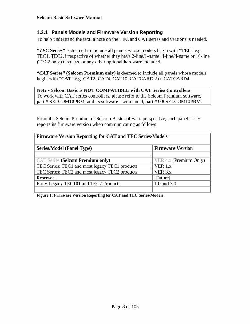
1.2.1 Panels Models and Firmware Version Reporting To help understand the text, a note on the TEC and CAT series and versions is needed. “TEC Series” is deemed to include all panels whose models begin with “TEC” e.g. TEC1, TEC2, irrespective of whether they have 2-line/1-name, 4-line/4-name or 10-line (TEC2 only) displays, or any other optional hardware included. “CAT Series” (Selcom Premium only) is deemed to include all panels whose models begin with “CAT” e.g. CAT2, CAT4, CAT10, CATCARD 2 or CATCARD4. Note - Selcom Basic is NOT COMPATIBLE with CAT Series Controllers To work with CAT series controllers, please refer to the Selcom Premium software, part # SELCOM10PRM, and its software user manual, part # 900SELCOM10PRM. From the Selcom Premium or Selcom Basic software perspective, each panel series reports its firmware version when communicating as follows: Firmware Version Reporting for CAT and TEC Series/Models Series/Model (Panel Type) Firmware Version CAT Series (Selcom Premium only) VER 4.x (Premium Only) TEC Series: TEC1 and most legacy TEC1 products VER 1.x TEC Series: TEC2 and most legacy TEC2 products VER 3.x Reserved [Future] Early Legacy TEC101 and TEC2 Products 1.0 and 3.0 Figure 1: Firmware Version Reporting for CAT and TEC Series/Models

Selcom Basic Software Manual
Page 9 of 108
1.3 What is Selcom Basic Software Used For? Selcom Basic is a programming software package that provides an easy means of setting features and directories using a regular PC and then “send” them to the access controller. The software also allows users to “get” the same information back from the controller also if you need to, and to “get” regular activity logs from the panel capable of keeping activity logs. Depending on the type of SES access control panel being used, many useful and at times complex features can be provided, e.g. timed access (schedules), amongst many others. Data about each access control panel is stored in “database” files on the PC being used. This method allows the Selcom software packages to be very powerful and flexible because they can manage any number of database files and controllers for different access control panels on different sites. Note – Only Selcom Premium Works with CAT Series Access Controllers One of the main feature restrictions in Selcom Basic (and TecBasic before it) is that it cannot work with CAT series controllers. That feature is retained for Selcom Premium.
1.3.1 Selcom Basic – New Features Selcom Basic is a free and reduced feature release of Selcom Premium, which evolved from Selcom 7, introducing new features over previous TecBasic versions as follows. Replacement of TecBasic 6.x.x with Selcom Basic software. This includes a
Selcom-7 style user interface that replaces the older TecBasic interface A new Simple Site Creator to replace the previous Add Wizard. A new Access Settings page for setting of Groups, Schedules and Access Levels A revised Systems Settings page Direct Ethernet / TCP/IP communications A revised Panel Configuration page, merging the Unit Data and Options pages A revised Entrance Settings page for more intuitive setting of available features New icons for easier recognition of main functions – these icons follow common
Mobile device usage practices Database file naming is now standardized for easier identification Database backups during communications are now saved to files with date-time stamps in
the filename for easier identification. Database files are now updated for future use on first startup. The existing files are first
backed-up to a backup folder to allow recovery if needed Improved and faster communications A new Directory Viewer to replace the previous view Directory table and which
includes new and easier to use search features and usage counts A new user login management screen, where administrators can add and remove users
and apply different levels of access to Selcom features.

Selcom Basic Software Manual
Page 10 of 108
1.3.2 Selcom Premium Additional Features Selcom Premium offers additional features that are restricted from Selcom Basic. Purchased copies of Selcom Premium have no feature restrictions – for more information, please see the following section on feature comparison.
Works with CAT series panels in addition to TEC series panels Ability to find and open detailed communications logs from past calls Ability to save log searches and open them again for viewing or printing A new RLY8 naming page showing all RLY8 relays on one page. Used in conjunction with the Simple Site Creator, the new communications task
“Get Configuration - No Checking” allows almost trivial setup of databases for SES access control panels, ideal both for installers of new SES products and those taking over maintenance of existing installations.
Separation of configuration and directory databases to allow use of the same directory for different types of CATs and TECs in multiple panel applications
A Call Log viewer showing overall results of communications to all panels called A manage panels page allowing changing of database filenames, modems and serial ports Ability to copy from a Terminal screen and paste it into your preferred simple document
editor e.g. Notepad or similar.
1.3.3 Overview of Features Introduced into Selcom 7.0 If you are familiar with TecBasic or Selcom versions 6.0.x or earlier, but not with Selcom versions 7.0.x, the following overview may help. Note – There is NO TecBasic Version 7.0 TecBasic version 6.0.4 was a free legacy application available after Selcom Secured (v6.0.x) was replaced with Selcom 7. No TecBasic version 7 has ever been released. Selcom 7 introduced several features unavailable in version 6 software or earlier: A completely new communications page, allowing multiple calling and “hands-
free” operation Scheduling - this includes pages to assign and manage call schedules, view future
updates and to manage Call Lists Time updates – the ability to send the current time of your PC to a panel. This
feature can be used to set up the time for a new panel, or to provide the semi-annual updates related to Daylight Savings Time (“DST”)
TCP/IP (i.e. Ethernet) – this allows Selcom to use direct Ethernet network-based communication with access control panels containing NIC cards and eliminates the need to install and use third party Com-port redirection software.
TCP/IP both for automatic data transfer, and in “Terminal” mode, matching the terminal emulation features already available in Selcom for modem and serial communications
An Ethernet-based “find” panels utility – this finds panels already connected to the same network.
An increased minimum resolution of 1024x768 to support newer features

Selcom Basic Software Manual
Page 11 of 108
1.4 Feature Comparison between Selcom Premium and Selcom Basic Selcom Premium and Selcom Basic differ in several ways, as listed in the table below. Selcom Basic is free software and as such has a reduced feature set. It can be downloaded from the SES web page for working with TEC series access control panels. It can be used to call one access control panel at a time. Feature Comparison between Latest Selcom Premium and Selcom Basic
Feature Premium Basic Compatible Controllers Stores data for and communicates with TEC1 Y Y Stores data for and communicates with TEC2 Y Y Stores data for and communicates with CAT Y -
Basic Calling Functions Send Configuration Y Y Get Configuration Y Y Get Configuration (No Checking) Y - Get Directory Y Y Send Whole Directory Y Y Send Directory Updates Only Y Y Clear Directory Updates Flag Y Y Get Log Y Y Acquire Raw Log Y Y Erase Log Y - Send Test Y - Send Date and Time (Current PC) Y - Use MUI IDs for modem calls Y Y Call Multiple Controllers (non-MUI) Y -
Advanced Calling Features Create, Manage and Load Call Lists Y - Create, Manage and Load Call Schedules Y - Set Future Directory Updates Y - Run Call Scheduling Y - View Call Log Y - Set Diagnostics Calls Y - Terminal Mode Calls (Serial Modem TCPIP) Y Y Figure 2: Feature Comparison between Selcom Premium and Selcom Basic

Selcom Basic Software Manual
Page 12 of 108
Feature Comparison between Latest Selcom Premium and Selcom Basic (Continued) Feature Premium Basic Other Advanced Features Allow separate databases for directory and configuration to allow same directory to be used for multiple controllers of different types
Y -
View Event Logs Y - Print Event Logs Y - Bulk loading for pins and cards Y Y Name RLY8 relays for Elevator or advanced relay control Y - Find NIC2 Controllers on Local Ethernet Y - Display PC Local IP address and User Name on Find Ethernet Controllers
Y -
Manage Panels Screen, where users can see all panels at once and change details such as modems or databases
Y -
Figure 3: Feature Comparison between Selcom Premium and Selcom Basic - Continued 1.5 Different Models (Panels) and Communication Methods All current SES models, whether belonging to the TEC or CAT series, can communicate using serial, modem or Ethernet (TCP/IP) depending on the type of controller and the installed options. Please consult your installer for more information. Your installer is responsible for correctly installing all of the hardware needed to control access to your property and for setting up the specific communications method(s) available to you according to the model. The installer is also responsible for showing you how to use both the software and the access control panel.

Selcom Basic Software Manual
Page 13 of 108
1.6 Features Not Discussed in this Manual
1.6.1 CATs As Selcom Basic cannot work with CAT series panels, there will be no discussion of CAT-related software features in this manual. Please refer to the Selcom Premium software user manual 900SELCOM10PRM.
1.6.2 Selcom Premium Features Features exclusive to Selcom Premium as listed in the feature tables of section 1.4 will not be discussed in this manual. For treatment of these, please refer to the Selcom Premium software user manual 900SELCOM10PRM.
1.6.3 Touch Tones and Keypad Operation Many functions, including those outlined above, can be programmed using a “touch tone phone”. For treatment of this subject, please refer to the relevant panel installation instructions, as both touch tone programming and keypad entry operations are topics outside the scope of this software manual. Please contact your dealer for more information. 1.7 Understanding Features of an SES Series Access Control Panel
1.7.1 Ways to Gain Entry to a Property There are several ways a visitor can gain entry to a property through a particular entrance or door.
Using the directory search on the front of the controller to select and dial a resident, then waiting for a response and requesting access verbally. To let the visitor in, the person being visited hears a phone ringing and answers it using a touch tone phone to converse with the visitor. Once satisfied, the owner grants access to the visitor by pressing a specific number key on the phone.
Using a valid PIN Using a valid card Using a valid RF clicker (treated the same as a card) Simply entering through an entrance already held or “latched” open. Latching can
be performed by management using a touch tone phone or the controller keypad, or, automatically in advance using “auto unlock”, where a time schedule is used to keep the entrance open for a period of time. This method provides no direct security.
Some concepts and terms are needed to understand these options.

Selcom Basic Software Manual
Page 14 of 108
1.7.2 Concepts and Terms Used
1.7.2.1 Access Time Schedules (AKA “Time Zones”) and What Are They? You can create “Access Time Schedules”, or more simply, “Schedules”. Schedules can be used by the access control panel to allow access onto your property during certain time periods on specific days i.e. schedules define “active” times and days. Note: Time Zones For many years the Access Control Industry has referred to “Time Zones” when referring to active periods. However, this usage conflicts with the formally recognized and worldwide use of “Time Zones”, which relates to how the local time changes as you travel East or West across the world. In the USA, the Eastern, Central and Pacific Time Zones are examples. To avoid ambiguity, both this manual and the software refer to Access Time Schedules, or just simply “Schedules”. In TEC1CA and TEC2 series controllers, eight schedules (Schedules 0 through 7) can be uniquely defined by the owner/operator. A schedule consists of several parts:
An “active” time span within a 24-hour period, defined by a start time and a stop time. An example of an active time span is from 8:00 am to 6:00 pm. Note however, a time span cannot cross a midnight boundary. For example, a time span of 10 pm to 6 am would require two schedules: 10 pm to 12 am and 12 am to 6 am.
Active days during a normal week. These are the days of every week on which the active time span should apply. In the software, days of the week are referred to by the first two letters of the day name i.e. Su Mo Tu We Th Fr and Sa respectively. An example of active days is Mo Tu We Th Fr and corresponds to Monday through Friday.
A special group of Exclusion dates, referred to as “Holidays”, which can also be included in a schedule. The Holidays group consists of dates instead of days-of-the-week and up to ten specific dates, not days, based on normal calendar months can be entered e.g. 0701 is Canada Day, 0704 is Independence Day in the US; 1225 is Christmas Day and so on. Holiday dates are not pre-programmed into the software, so it is for the operator of the property to decide what dates (if any) should be included in the Holidays group to be used for exclusion purposes. Care should be taken to avoid using Feb 29th as a holiday since this is valid only on Leap Years (once every four years). Use of Holidays is an advanced topic covered in section 7.4 on editing Access Schedules.

Selcom Basic Software Manual
Page 15 of 108
Once defined, a schedule number can be selected for various functions, and each schedule can be used as many times as desired. Limiting access for visitors PINs (see following sections) Limiting access for visitors with cards or RF clickers (see following sections) Providing automatic locking and unlocking of Doors/Entrances (1 to 2 for TEC1,
1-4 for TEC2)
1.7.2.2 PIN Code A PIN code is security jargon for Personal Identification Number. If you have used an ATM to do some banking, you have already used a PIN. The idea is similar but there is no card involved. To use a PIN to gain access into a property, you press the “*” key on the controller keypad, followed by the PIN digits. If the PIN, the entrance or door it is programmed for, and the schedule, are all valid, the controller will grant access to unlock/open the door. SES controllers recognizes as many different PINs as there are directory entries allowed (referred to as “Capacity”). Frequently, we will refer to PIN as Pin.
1.7.2.3 Cards and RF clickers For TEC1CA and TEC2 models, all cards and RF clickers are counted as CARDs, and there is ONE card per directory entry. Cards and RF clickers alike must be “26-bit Wiegand compatible” to operate with SES products, although other types can be used if the signal is processed by a converter first. To be “read” cards must be swiped by a card reader connected to the controller. RF clickers, which contain an RF transmitter operated when a RF clicker button is pushed, must be “read” by an RF receiver, which must also be connected to the controller. Please consult your dealer for more information about your hardware configuration.

Selcom Basic Software Manual
Page 16 of 108
2 Selcom Basic Software Installation 2.1 Compatibility with Microsoft Operating Systems Warning: Operating System Compatibility SES deems Selcom Basic software to be compatible only with those Microsoft Windows 32 and 64-bit operating systems licensed for use in either the USA or Canada and whose Extended Support Life Cycle is still current. Users install Selcom Basic software AT THEIR OWN RISK. Microsoft Operating Systems Compatibility Table (Source of Microsoft data: http://windows.microsoft.com/en-us/windows/lifecycle) Operating System (Licensed for Use in the USA and Canada)
Latest Update (at Jan 2015)
End of Mainstream Support (Date)
End of Extended Support (Date)
Windows 10 July 29, 2015 October 13, 2020 October 14, 2025 Windows 8 Windows 8.1 January 9, 2018 January 10, 2023 Windows 7 Service Pack 1 January 13, 2015 January 14, 2020 Windows Vista Service Pack 2 April 10, 2012 April 11, 2017 Figure 4: Operating System Compatibility Table WARNING This software will not install on operating systems earlier than Windows Vista. No amount of paid technical support will get around this. 2.2 SES Support Policy SES does not support software installation on operating systems not listed in the table in section 2.1 and/or which are outside of Microsoft Extended support period. SES takes reasonable steps to ensure that Selcom Basic software is compatible with the operating systems defined section 2.1. However, as Selcom Basic is freely available for download from the SES website, the user accepts and agrees that SES has no liability for its installation or use and is under no obligation to provide free support for the product. Users may be required to pay for technical support, but irrespective of payment SES does not accept liability for the consequences of providing such support, paid or otherwise.

Selcom Basic Software Manual
Page 17 of 108
2.3 SES Software installation If the software was provided on a CD, double-click on Setup to begin. If instead the software was downloaded from the SES website (Selcom Basic ONLY), extract the files from the downloaded zip file first and then double-click on the extracted Setup.exe file to begin. You will see the Welcome dialog box as shown:
Figure 5: Install Software Dialog for Selcom Basic Click on “Next” to continue. After a brief interval, the green bar will display overall installation progress.
Figure 6: Install Progress Dialog for Selcom Basic A dialog box will notify you when the installation is complete.
Selcom Basic Software Manual
Page 18 of 108
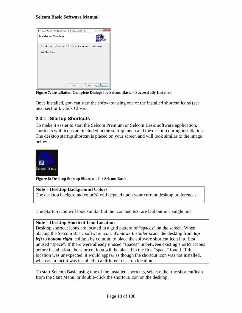
Figure 7: Installation Complete Dialogs for Selcom Basic – Successfully Installed Once installed, you can start the software using one of the installed shortcut icons (see next section). Click Close.
2.3.1 Startup Shortcuts To make it easier to start the Selcom Premium or Selcom Basic software application, shortcuts with icons are included in the startup menu and the desktop during installation. The desktop startup shortcut is placed on your screen and will look similar to the image below:
Figure 8: Desktop Startup Shortcuts for Selcom Basic Note – Desktop Background Colors The desktop background color(s) will depend upon your current desktop preferences. The Startup icon will look similar but the icon and text are laid out in a single line. Note – Desktop Shortcut Icon Location Desktop shortcut icons are located in a grid pattern of “spaces” on the screen. When placing the Selcom Basic software icon, Windows Installer scans the desktop from top left to bottom right, column by column, to place the software shortcut icon into first unused “space”. If there were already unused “spaces” in between existing shortcut icons before installation, the shortcut icon will be placed in the first “space” found. If this location was unexpected, it would appear as though the shortcut icon was not installed, whereas in fact it was installed in a different desktop location. To start Selcom Basic using one of the installed shortcuts, select either the shortcut/icon from the Start Menu, or double-click the shortcut/icon on the desktop.

Selcom Basic Software Manual
Page 19 of 108
2.3.2 Remove or Repair Installation If there was an error or a previous installation, you will see a dialog box like this:
Figure 9: Repair Software Dialog with Repair Button Selected You may decide to Repair or remove the installation to correct any issues. If you decide to remove the installation, you will see this dialog box:
Figure 10: Remove Software Dialog Button with Remove Button Selected You will be notified with a new screen that the installation has been successfully removed. After resolving any Windows issues, you may perform the software installation again. If you choose to Repair, then Windows will repair the installation and continue to install normally. Once the installation is complete, you will see a normal Installation Complete dialog box at the end of installation.

Selcom Basic Software Manual
Page 20 of 108
Figure 11: Remove or Repair Progress If you chose to Remove, you will see an Installation Complete dialog box which states that the software was successfully removed.
Figure 12: Installation Complete Dialog – Successfully Removed Click Close to finish.

Selcom Basic Software Manual
Page 21 of 108
3 Selcom Basic Software Quick Start 3.1 What is the Quick Start For? This software allows you to program your panel’s settings using your PC, which is much easier than doing so manually. The Quick Start part of this manual is primarily intended to be able to quickly help you communicate between your PC and your panel, and to show you how to program a simple Directory entry.
3.1.1 Sample Databases for Panels When you start up the software, you will notice that it has no reference to your own building or site. Instead you will see sample databases for SES panels – Sample Tec1, Sample Tec2. These have been created to demonstrate what settings and pages look like. Feel free to browse through these to give you an idea of what the software can do and the capabilities of the different panel model types. 3.2 The Basics
3.2.1 Collect Your Site Information Before you start entering settings for your controller, you will need to collect some information and make some decisions. Did the installer give you written information about how you connect to the
controller using the software provided (e.g. telephone number, serial port or IP address and port, panel password and unit ID)? Did the installer try it out for you?
How many controllers do you have? What do you wish to name each controller? It may help to consider the physical location of the controllers.
How many doors/gates/entrances does each controller have to control? What would you name entrances?
Consider all the people who need access to your facility. You will need to divide these up into groups depending on how often they need access, the entrance they can use, and whether they are temporary, seasonal or occasional visitors.
Are there any times or days when you simply need to leave a gate open for an extended time, and if so, which one and for what times?
Will residents need PINs or cards, or both? If so, what range of numbers does your installer advise you to use?
Once you have collected information on this list, you can start to use the software to enter the information.

Selcom Basic Software Manual
Page 22 of 108
3.2.2 First Time Startup – IMPORTANT! On first startup, the software will check for a file location called the Working Folder. If no folder or files exist, this will have been the first time you have run the software after installation on this PC, irrespective of whether you may have previously used it on another PC. If this is the case, both Selcom Premium and Selcom Basic will show a dialog explaining that it will copy some default (startup) files to the Working File Location. The dialogs for Selcom Premium and Selcom Basic are shown as follows:
Figure 13: Selcom Basic First Time Startup - Copy of Default Files to Working File Location The location of the Working Folder for Selcom Basic is shown below.
Figure 14: Location of Selcom Basic Working Folder However, you will only need to know this if you have previous Selcom Basic or TecBasic files to copy from another location. In this case the easiest way will be to copy your files from the previous location onto a USB flash drive, and then copy the files into the Working File Location created by your newly installed software. WARNING Please DO NOT attempt to copy the files before first time startup of the software after installation, because the working folders will not exist until the first time startup has been performed.

Selcom Basic Software Manual
Page 23 of 108
Selcom Basic Software Manual
Page 24 of 108
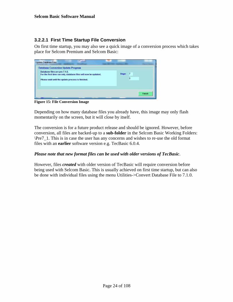
3.2.2.1 First Time Startup File Conversion On first time startup, you may also see a quick image of a conversion process which takes place for Selcom Premium and Selcom Basic:
Figure 15: File Conversion Image Depending on how many database files you already have, this image may only flash momentarily on the screen, but it will close by itself. The conversion is for a future product release and should be ignored. However, before conversion, all files are backed-up to a sub-folder in the Selcom Basic Working Folders: \Pre7_1. This is in case the user has any concerns and wishes to re-use the old format files with an earlier software version e.g. TecBasic 6.0.4. Please note that new format files can be used with older versions of TecBasic. However, files created with older version of TecBasic will require conversion before being used with Selcom Basic. This is usually achieved on first time startup, but can also be done with individual files using the menu Utilities->Convert Database File to 7.1.0.

Selcom Basic Software Manual
Page 25 of 108
After first-time conversion, starting the software will display the appropriate user login screen:
Figure 16: Selcom Basic Login Dialog If this is your first time, type “ses” into the username, press Enter, and then type “ses” into the password field, (both fields are case sensitive) then press Enter again. Once logged-in, you will see the Main Page:
Figure 17: Selcom Basic Main Page - No Panel Selected Selcom Basic includes active “Did you know?” hints to the left of the screen

Selcom Basic Software Manual
Page 26 of 108
3.2.3 Selecting a Panel from the Drop-Down List
Figure 18: Startup Page Drop-Down List after First Time Startup Clicking the small arrow to the right of the drop down combo will open the list of available panels which, on first time startup, will only list names for example databases. Left-click a name in the list to select that site’s database. You will now see the main page with a lot of buttons along the middle, and more menu options along the top. Note – Availability of Main Buttons and Menu Options Except for the Finished and the Add Panel buttons, other buttons allowing you to work with specific panel database files are not available if no panel is currently selected.
Figure 19: Sample Site Selected Unless you want to click on the various buttons to have a look (it won’t do any harm), the first thing you will need to do is to add a new panel, as shown in the next section.

Selcom Basic Software Manual
Page 27 of 108
3.2.4 Adding a Site (or Panel) Whether you already have a site selected, or none at all, you can still add a new panel. To add a new panel, click the Add Panel button.
Figure 20: Location of Add New Panel Button, With and Without, a Site Already Selected This function is also available by clicking the Simple Site Creator entry under the File menu button at the top left. You will see the Simple Site Creator dialog as shown below.
Figure 21: Simple Site Creator Dialog Inside the dialog, type the name you wish to call the panel in the “New Name” text box. Once you start typing the name, the Create button will become enabled. The new name is whatever you want to call the panel e.g. in relation to the facility, gate or entrance etc. If you want to change the name later you can do so using the Edit Panel Data menu option at any time. In our example, we have entered “My New Site” as the panel or site name.

Selcom Basic Software Manual
Page 28 of 108
Note Your installer may have already done this and other basic steps for you – if so, you can skip to whatever section you need. When ready, click Create. After doing so, you will see the confirmation screen that the site has been created:
Figure 22: Confirmation of Created Site The confirmation includes two important pieces of information: the name of the site created (“My New Site” in our example), and the new “.mdb filename” assigned, shown above as “Ndb0004”. When creating a database, the simple site creator always starts by assuming a model of TEC1, and sets firmware version and values accordingly. These settings are easy to change by selecting the site and editing the panel data, as shown in the next section. Note NO communications settings are assumed on creation – these must be entered when editing panel data. Click OK on the confirmation page. You will be returned to the main page, as though you had just started up. Note - Examples Showing Database File Numbers Within this manual, the database numbers may vary between examples. Such differences should be ignored as they do not affect the accuracy of the examples.

Selcom Basic Software Manual
Page 29 of 108
3.2.4.1 A Word about GlobalD.mdb When creating a site, a new record is added to a file called “GlobalD.mdb”. Amongst other data, this entry contains the new site name and the filename of the new database file created. When editing data, as shown in the next section, some of the data edited e.g. communications settings, is changed within the GlobalD.mdb file record for that site. Whenever a list of available sites is needed, the GlobalD.mdb file is referenced to create the drop down list of sites on the Main Page. The order displayed is actually the order in which the sites were created. Every time a new site is created, a new database file is also created, and will be used to hold directory information, access settings and detailed panel configuration information. The number within the filename is created by incrementing the count used in the latest database filename within the GlobalD.mdb file. Database filename numbers are not re-used.
3.2.5 Reselecting the Site At this point you will need to select the new site you have just created. To do so, click the drop down box, as shown below.
Figure 23: Selecting the New Site Just Created As you can see, the drop down box now includes the new site name in the list. Select your new panel from the drop down list. Once selected, this is the panel you will work with until you select a different panel.

Selcom Basic Software Manual
Page 30 of 108
Figure 24: New Site or Panel Selected Information about the panel selected is displayed in the pane towards the top right of the screen. This is always a good way to tell if you are working with the panel expected. Note – You Can Set a Preferred Startup Site to Work With Frequently If you are likely to work with a panel frequently, you can set it as the Preferred Startup panel as shown in the next section. In fact, you can “mark” several sites this way, but it is a good idea to have only one preferred site or panel.

Selcom Basic Software Manual
Page 31 of 108
3.3 Editing the Panel Data
3.3.1 Selecting a Communications Method for Your Site Each site can have its own Communications Method. For a Selcom Premium/Basic application, the Communications Method refers to the physical hardware the application uses to connect to an Access Control panel. The possible Methods are:
Serial - An RS232 cable from the Selcom PC with a COM port directly to a panel. The COM port might be a real COM port on the back of the PC, or, common in today’s PCs, a COM port via a USB-Serial adapter.
Modem - A dial-up telephone line between a Selcom PC modem and the panel. The PC may have a physical modem installed, or it may have a USB modem, common in today’s PCs.
TCP/IP (Ethernet) An Ethernet network cable on a common subnet linking the PC to a NIC2 card installed on the panel.
3.3.2 Selecting a Modem and Setting the Panel Phone Number On first entering the Edit Panel Data screen after site creation, you will see that there is a “reminder” message requesting you choose a modem. This reminder occurs because many PC users program SES access controllers from locations many miles from the controller itself, so often the only way to communicate with these sites is by phone. The message is also a useful reminder if the database has been transferred from another PC and the modem information has not been updated to match the available modem on the current PC. Notice that in the Communications pane, there are option buttons for Modem, Serial or TCPIP (Ethernet). On first time creation, the default setting is Modem, but you can select a different method any time by clicking on the option button for your preferred method.
Selcom Basic Software Manual
Page 32 of 108
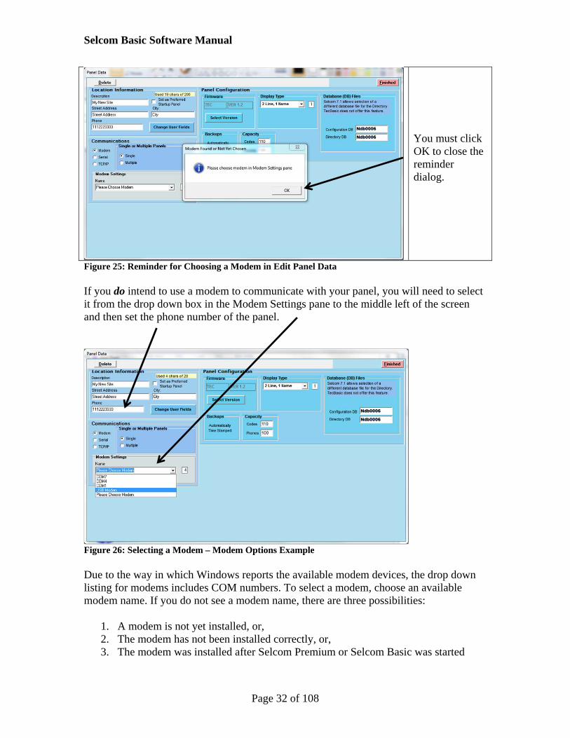
You must click OK to close the reminder dialog.
Figure 25: Reminder for Choosing a Modem in Edit Panel Data If you do intend to use a modem to communicate with your panel, you will need to select it from the drop down box in the Modem Settings pane to the middle left of the screen and then set the phone number of the panel.
Figure 26: Selecting a Modem – Modem Options Example Due to the way in which Windows reports the available modem devices, the drop down listing for modems includes COM numbers. To select a modem, choose an available modem name. If you do not see a modem name, there are three possibilities:
1. A modem is not yet installed, or, 2. The modem has not been installed correctly, or, 3. The modem was installed after Selcom Premium or Selcom Basic was started

Selcom Basic Software Manual
Page 33 of 108
In all three cases you MUST close down the Premium/Basic application, THEN fix the problem, and then restart the application again once you know the modem has been installed correctly. This is because if a modem is not installed correctly, Windows may not report it correctly to Selcom Basic, which is done only on application startup. Once the modem is set, you will need to enter a telephone number for the modem to dial when communicating with the panel. This is the phone number assigned to the telephone line on which the panel is installed. The phone number you enter must obey the normal rules of dialing. Please consult your installer and type the phone number into the “Phone” text box shown in the Figure “Selecting a Modem - Modem Options Example” above.

Selcom Basic Software Manual
Page 34 of 108
3.3.3 Setting Serial Communications Serial communications act as a direct link between the PC and the panel/site being programmed. Except for unusual circumstances, most often the PC is a laptop and is physically connected directly to the panel using a serial (RS232) cable within recognized serial cable distance limits. To select Serial communications for this panel, you will need to choose Serial from the radio buttons in the Communications pane (see the figure Selecting Basic Serial Settings).
Figure 27: No Serial Port Message If you see the No Serial Port message on entering this page, click OK to continue.
Figure 28: Selecting Basic Serial Settings Once you have selected the serial communications option, you will need to select a serial port. Click the Com Port drop down box to select the com port if you know it. (Unless you know what you are doing, leave the Baud Rate at 9600.) If you don’t know the port number but are sure that you are physically connected to the panel using a serial cable, or if more advanced serial communications settings are needed (i.e. the Baud Rate), please consult your installer first.

Selcom Basic Software Manual
Page 35 of 108
Click the Com Port drop down box and select the correct Com Port. In our example, a panel was detected at COM1, so “1” is selected as shown below.
Figure 29: Serial Com Port Set

Selcom Basic Software Manual
Page 36 of 108
3.3.4 Setting TCPIP (Ethernet) Communications Selcom Basic is network capable, so it can use TCP/IP (Ethernet) to communicate with panels already configured with NIC2 cards and that exist (or have been enabled to be seen) on the same subnet as the PC being used for Selcom Basic. TCP/IP can be used to communicate with panels automatically using the Automatic Interface. This is similar to performing automatic send and receive of full directories and logs in previous versions using modem or serial methods. TCP/IP can also be used to provide menu-driven interfaces for making discrete changes to panel directories and configurations. To select TCPIP, click the TCPIP option button.
IP address Port (Default 10001) Apply
Figure 30: Edit Panel TCPIP Settings Once the TCPIP option button is selected, the Ethernet Settings pane is displayed. In this, you can set the IP address and Port associated with the NIC2 panel you are going to connect with. When you have set these values, click the Apply button. If you are not sure of the values to use, please consult your installer.

Selcom Basic Software Manual
Page 37 of 108
3.3.5 Setting the Preferred Startup Panel Every time you start the application, you will need to select the panel database you wish to work with. If you have several different sites, this would be quite normal. However, if you only have one site, or a main site that you need to work with most frequently, you can tell the application to load the data for this site automatically on startup. The setting for this is called the “Preferred Startup Panel”, previously known as the “Default” Site or Panel. In the Edit Panel Data page, there is checkbox “Set as Preferred Startup Panel”. You can check or uncheck it as you please. Its location is shown in the figure below.
Figure 31: Location of Preferred Startup Panel Checkbox

Selcom Basic Software Manual
Page 38 of 108
3.3.6 Setting the Panel Version In Selcom Premium, this step is not necessary, due to the ability to call a panel and use the recently-introduced “Get Configuration – No Checking” option. However, this must be done in Selcom Basic, otherwise communications errors may occur. To set the panel version, return to the Edit Panel Data page if you are not already there. Click on the blue “Select Version” button in the Panel Configuration pane.
Figure 32: Setting the Panel Version This opens the firmware/model selection pane. For now, select the version you believe best matches your product. (Notice that the CAT versions are disabled because Selcom Basic cannot work with CATs.) We have selected a TEC2 latest version panel.
Figure 33: Selecting the Version

Selcom Basic Software Manual
Page 39 of 108
In the panel configuration, the Firmware has been changed to your selection. However, you will now notice that the Display Type states “Choose Model” and has a yellow background.
Figure 34: Reselect Display Type after Changing Version The display types available will depend on the firmware version you selected. Use the yellow drop down box to change the type.
Figure 35: Display Type Selected Click Finished when done.

Selcom Basic Software Manual
Page 40 of 108
3.3.7 Setting the Password and Unit ID for Panel Communications Irrespective of the method used to call a panel (modem, serial or TCP/IP), once connected, the software will need to provide credentials (i.e. a password) in order to continue to communicate with the panel. It will also need to confirm it is communicating with the correct panel (Unit ID) for modem or multiple unit (MUI) situations. The password and non-MUI Unit ID are set using the Systems Settings screen. To get there, from the Main Page, click on the Systems Settings button (with the gear wheel).
Figure 36: Location of Systems Settings Button The password and Unit ID are shown on the System Settings screen below.
Figure 37: Location of Password and Unit ID

Selcom Basic Software Manual
Page 41 of 108
For now we are only concerned with the Programming Password and the Unit ID. This is information that should be confirmed by your installer before entering the data into the screen. All SES access control units leave the factory with the Programming Password set to “777777” (i.e. six 7’s) and a Unit ID of 3. If your installer has changed either of these in the panel itself, you will need to enter the information provided by the installer into the appropriate text box in the “Existing Identifications” pane. Do not be concerned with the “Update to a New Password” pane at this time – this feature is used only on an as needed basis. If you need to enter a new programming password, it MUST contain six digits (each can be 0 – 9). Enter this new password into the Programming Password text box. For unit IDs (aka Ring Count), use this page if you do not have Multiple Units (MUIs) on the same phone line. If you do have multiple units then you must enter Unit IDs into a small table on the Edit Panel Data page, and click on the “Multiple” option in the Single or Multiple Panels frame, then set the number of panels on the phone line and click the button “Edit Unit IDs”. See the sub-section on Setting up Multiple Panels (MUIs) in section 6. A unit ID can be only one digit, in the range 2 – 9 [‘1’ is avoided because the unit could respond to a telephone line glitch that looks like a ‘1’.]. Enter the new Unit ID into the “Unit ID (Non-MUI)” text box. Note – Unit IDs or Ring Counts The Unit ID, or Ring Count, is used in multiple unit installations where more than one SES access controller (panel) is sharing the same telephone line. The idea here is that each panel can be told how many times the phone line “rings” before it should try to answer an incoming call. This method, when used with the “sleep” command (automatically used by Selcom Basic in MUI situations), allows each panel in an MUI setting to be called in order of its Unit ID, or Ring Count. Although Unit ID is not strictly used in Serial mode, many users with multiple panels prefer to have separate IDs for each panel. In TCP/IP, the unit ID is not used, as the combined IP address and TCP/IP port number are unique within any subnet. When done, click the “Finished” button to take you back to the main page.

Selcom Basic Software Manual
Page 42 of 108
3.4 Trying Out the Communications Settings Before going any further, it is recommended that you try out the communications settings you have just entered into the database. To do this, you will need to enter the communications page. Click on the Automatic Interface button to the right of center as shown below.
Figure 38: Clicking on the Automatic Interface Button for Communications The Communications page on first entry is shown in section 3.4.1. Note that details of the panel selected on the Main page are now displayed on a yellow highlighted line or “entry” in the “Call Table” area. Each entry has “fields” whose meaning is described by the different column titles e.g. “Location” and “ID”. A formal review of the page can be found in the reference in section 4.1.

Selcom Basic Software Manual
Page 43 of 108
3.4.1 Quick Get Directory Example The following example, based on examples created previous to this manual, will demonstrate how to get a panel’s Directory using TCP/IP (Ethernet) communications. In our “My New Site” example, the Communications page shown again below.
Figure 39: Initial Entry into Communications Screen Prior to Setting a Get Session Once the panel has been added to the Call Table as shown in the figure above, we can set it to get the Directory from the panel. To do this, we will select the desired task from a mouse menu. However, as mouse menus in Selcom are context-sensitive, we must first move the mouse pointer to the location on the table so that left-clicking will display the menu options we need. Locate the entry on the Call Table starting with our panel location (in our example this is the yellow line that starts with “My New Site” at the far left). Move the mouse along the line towards the right until the mouse pointer is under the green column heading “Dir.” under the green main heading “Assigned Session Tasks”. Use the mouse left-click to display the context-sensitive menu. This menu will display various options for assigning session tasks (no screenshot available). We are interested in

Selcom Basic Software Manual
Page 44 of 108
the first available mouse menu option i.e. “Get Directory”. Left click this menu line to place a “G” in the field where the mouse was pointing, as shown below.
Figure 40: Call Table – Setup for Get Directory Once set up is complete, click the light blue “Start Comms” button in the “Current Activity” pane of the “Communications Overview” panel. Communications will immediately commence, as shown in the next figure.

Selcom Basic Software Manual
Page 45 of 108
Figure 41: Call Table When Communications Have Started Note that the Call Table line entry is a bright yellow background that signifies the panel on the current line is being called i.e. is the Active entry in the Call Table. Depending on the task(s) chosen, indicators within the Current Activity area will display relevant status or progress information. However, the most important status indicator is the Progress Display. This is the white box to the far right of the Current Activity pane. The Progress Display is useful from two main aspects. Firstly, it provides a visual listing of progress throughout the call and what issues if any were encountered. This is useful for hands-on setup and diagnostics. Secondly, and new to Selcom Basic, Progress Display information for ALL sessions are saved to a communications log file, known as a “Comms Log”. Please refer to the section 3.6 for more information.

Selcom Basic Software Manual
Page 46 of 108
At the end of a session, the Progress Display will show the steps taken to finalize the call, and at the far right of the Call Table, the “Session Overall Results” field will display the final outcome, in this case “GD OK”. “GD” means, “Got” Directory, so the result is telling us that the task to get the directory was completed successfully.
Figure 42: Call Table Communications Successful Completion Notice that the active entry turned green. This is also a visual indicator of success. For failures, the background will become red.

Selcom Basic Software Manual
Page 47 of 108
3.5 The Directory – Granting Access to Your Property
3.5.1 How Access Can Be Granted The purpose of having an access controller is to allow selected visitors to access your property. There are three main ways in which an individual visitor can gain access:
1. Choose from a Directory List - Use the controller keypad to select an entry in the displayed directory. This causes the controller to ring a specific (hidden) phone number associated with that entry.
2. Enter a PIN Number - Use the controller keypad to enter a * followed by a six digit PIN number. The PIN is compared to entries and the Group number in the directory before allowing access. There is one PIN for every person listed.
3. Swipe a card or RF clicker – If the system is equipped with a card reader for reading cards, or an RF receiver for receiving “clicked’ transmissions from RF clickers (these transmit card numbers), the card number received is compared to entries in the directory and the Group number before allowing access. For TEC1CA and TEC2 panels, one card can be assigned to each person in the Directory. (For CATs, each person in the directory can be associated with up to 6 different cards, but these can be set only in Selcom Premium.)
Methods 1 & 2 are most commonly found at the outside entrance gates to the facility, or to specific buildings. Method 3 can be used anywhere e.g. providing car access into roadways or parking areas, or providing access into facilities such as swimming areas or club houses. For all methods there are other settings that relate to that particular setup. If a panel has a clock, then time schedules and entrance permissions can be created to determine when and where specific visitors have access. Note – Cards and RF clickers RF clickers and cards are programmed in the same way, so for simplicity, software-related references after this section will refer to cards only. For hardware-related information on cards and RF clickers, please refer to manufacturer documentation.

Selcom Basic Software Manual
Page 48 of 108
3.5.2 Directory Viewer - Sample TEC2 To get to the Directory page, on the Main Page, either click on the Directory View/Edit menu under the Edit menu, or click the View/Edit Directory. The sample view below shows the Directory of “Sample TEC2” included in the Selcom Premium software installation.
Figure 43: Directory Viewer Showing Directory of Sample TEC2 This page is the “Directory Viewer”, and is divided into areas on-screen: A Panel Capacity Usage pane at the top left of the screen. This tells you about the
capacity of codes and phones for the current site you are working with – what has been used so far and how much is still available. This is also color coded to help you identify whether you are approaching or have used your current capacity limits.
A pane for Marked Directory Entries – the meaning of this information is explained separately below in the section Marked Directory Entries
A Search pane. This feature allows users to search for specific entries in the table and is explained in the section Using Directory Search
The directory table itself that takes up most of the page containing names, numbers and other information. The information viewed in this table can be modified by clicking on a specific line in the table to enter Edit Mode.

Selcom Basic Software Manual
Page 49 of 108
Add New – click to add a new entry to the directory Help button provides basic information about how to use the Directory Viewer The Main Page button closes the Directory Viewer and returns the user to the
Main Page.
3.5.3 About the Directory View Table The directory table in the Sample View above consists of columns along with text-filled lines referred to as rows or “entries”. The number of columns varies according to the panel series selected, and in certain cases the firmware version. The column headings are: “Code” – this is a unique number assigned during first creation of the entry. All
subsequent data added for this entry must be saved by the software with respect to the code. Thus, once created, the code cannot be changed – only deleted.
“Flagged” – this column is actually made up a three smaller sub-columns and is concerned with the most recent history of the directory data. Flagged Column with Sub—Columns and Purpose Sub-Column
Purpose
Snd Indicates whether some data in this entry has been saved or re-saved by the user during editing. The flag acts as a reminder to the user that the data should be sent to the panel, or if already sent, that the flag needs clearing.
New This means “New from Panel” and is only relevant when performing a “Get Directory” operation. As described above, each directory entry is related to a unique “Code” that is stored on the PC database. Where the panel and PC directory data matches, every directory entry has a code that is used correspondingly in the panel. If a property manager decides to create a directory entry using the panel keypad or directly in Terminal Mode, then that entry, and its associated Code, will only exist on the panel. In order to add it to the PC database, it will have to be either entered manually using the Selcom directory editor, OR be obtained using the “Get Directory” operation. In the latter case, during the Get Directory operation, if the code just received from the panel was not in the current database, Selcom will mark this as a “New” from panel entry so that you know the data was not added using Selcom.
Del The user deleted this entry in the database so it must also be deleted from the panel the next time a Send Directory or Send Directory Updates operation is performed.
Figure 44: Table of Communications Flags (Snd, New and Del)

Selcom Basic Software Manual
Page 50 of 108
Code Owner - Name – this is the name of the person whose apartment, condo or
office will be dialed. Name Hide – some residents choose to hide their name from the visible directory
displayed on a channel. If this is set, their name is hidden from view on the panel. Phone Number – this is the phone number dialed by the panel when a visitor
chooses the name from the directory list. Visitors cannot see this number. PIN – residents can enter the PIN number into the panel keypad to gain access. Card1 – residents can use cards to clickers to gain direct access without using the
keypad Group – for the current row, think of this as a number restricting where and when
the PIN or cards associated with this entry are allowed access.
Selcom Basic Software Manual
Page 51 of 108
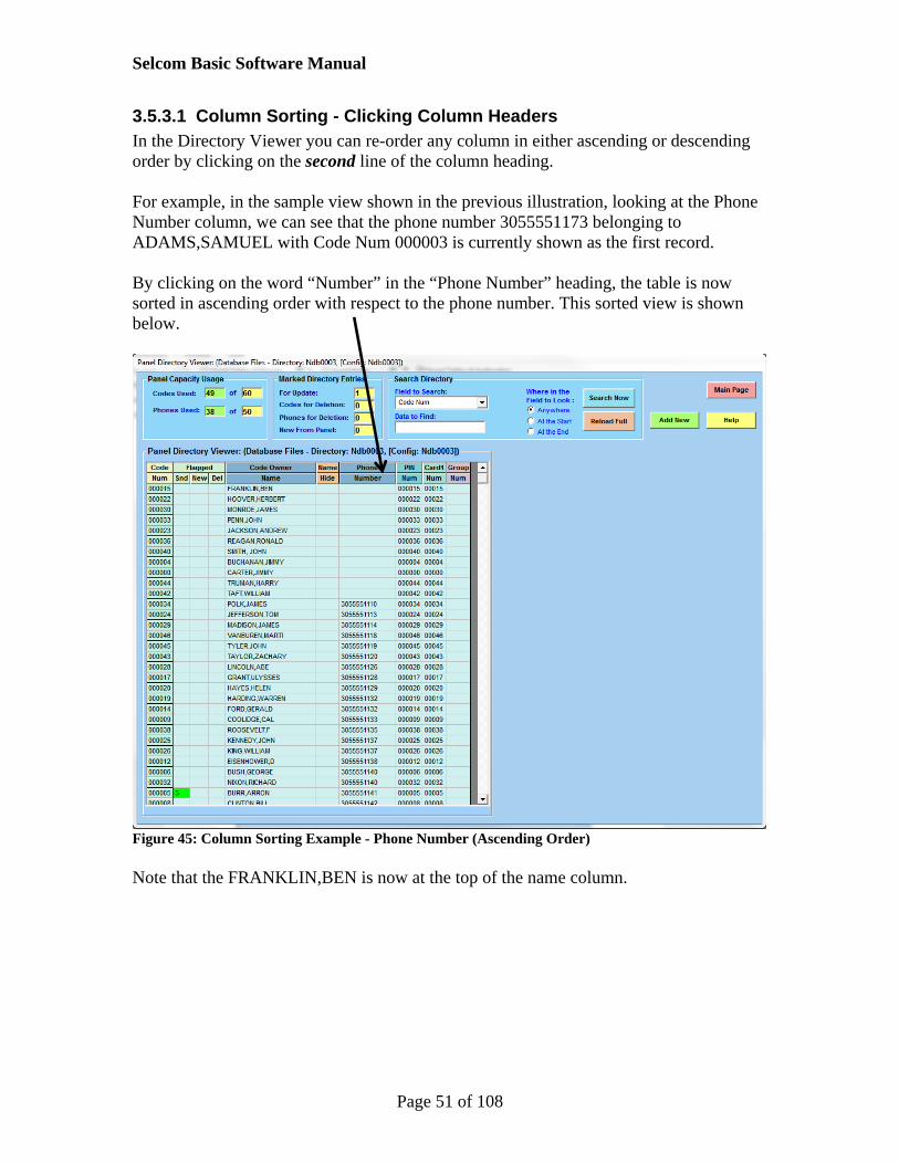
3.5.3.1 Column Sorting - Clicking Column Headers In the Directory Viewer you can re-order any column in either ascending or descending order by clicking on the second line of the column heading. For example, in the sample view shown in the previous illustration, looking at the Phone Number column, we can see that the phone number 3055551173 belonging to ADAMS,SAMUEL with Code Num 000003 is currently shown as the first record. By clicking on the word “Number” in the “Phone Number” heading, the table is now sorted in ascending order with respect to the phone number. This sorted view is shown below.
Figure 45: Column Sorting Example - Phone Number (Ascending Order) Note that the FRANKLIN,BEN is now at the top of the name column.

Selcom Basic Software Manual
Page 52 of 108
To sort in Descending order, click the word “Number” in the “Phone Number” heading again. The re-sorted table is shown below.
Figure 46: Column Sorting Example - Phone Number (Descending Order) Note that the FUDD,ELMER is now at the top of the name column. You can click the orange Reload Full button at any time to view the directory as it was first loaded. You can also perform as many sorts on different columns as needed, and click Reload at any time.

Selcom Basic Software Manual
Page 53 of 108
3.5.3.2 Searching the Directory The Search Directory pane is the box to the center right at the top of the directory page. It contains:
A “Reload Full” button A drop down box “Field to Search” A text box “Data to Find” Three option buttons under “Where in the Field to Look” A “Search Now” button
The “Reload Full” button reads all data in the directory and displays it in the order it is stored in the database. Think of this as a full data refresh function that can be used at any time. The “Field to Search” box contains a list of all the different fields (or columns) available in the current display. You can select any field to search. In the “Data to Find” textbox, type the data you wish to search for. The entries in this box are NOT case sensitive. Under “Where in the Field to Look”, click an option button to narrow the search within the field e.g. you might wish to search for all names beginning with certain characters. The “Search Now” button will initiate the search based on the selections and data entered. As an example, let us search for a name (Code Owner Name) beginning with the capital “C”. Select “Code Owner Name” from the drop down list, type capital “C” in the “Data to Find” box, and select the option “At the Start”. The selections are shown in close-up below:
Figure 47: Example of Name Search Criteria

Selcom Basic Software Manual
Page 54 of 108
Click the Search Now button to search for all instances of the capital letter “C”.
Figure 48: Search Results Example
3.5.4 Adding New Directory Entries To add a new directory entry, click the green Add New button on the directory viewer page.
Figure 49: Partial View of Directory of Empty Site “New Site 2” In this example we have already created a new empty “My New Site 2” using the Simple Site Creator.

Selcom Basic Software Manual
Page 55 of 108
Figure 50: Directory Add New Note that the fields displayed depend on the type of access controller (TEC1 or TEC2). Note also that some fields are referred to as User Fields. These are fields that can be entered by the user and stored on the PC for user convenience, but which are not used by the panel. You can view or hide them using the blue buttons in the User Fields pane. As an example we will use our “My New Site 2” and add a new directory entry. In the example, to avoid confusion, we have hidden both the Park Fields pane and the Notes pane by clicking on the blue buttons. Notice the pink display “Add New Mode” in the following example.

Selcom Basic Software Manual
Page 56 of 108
Figure 51: Directory - Adding New Data Click the green Save Changes button. Notice that the data you just entered is no longer displayed, but that we are still in Add New Mode. This is so additional directory data may be entered.
Figure 52: Directory after Clicking Save Changes For now, click Finished to see the data you just entered.
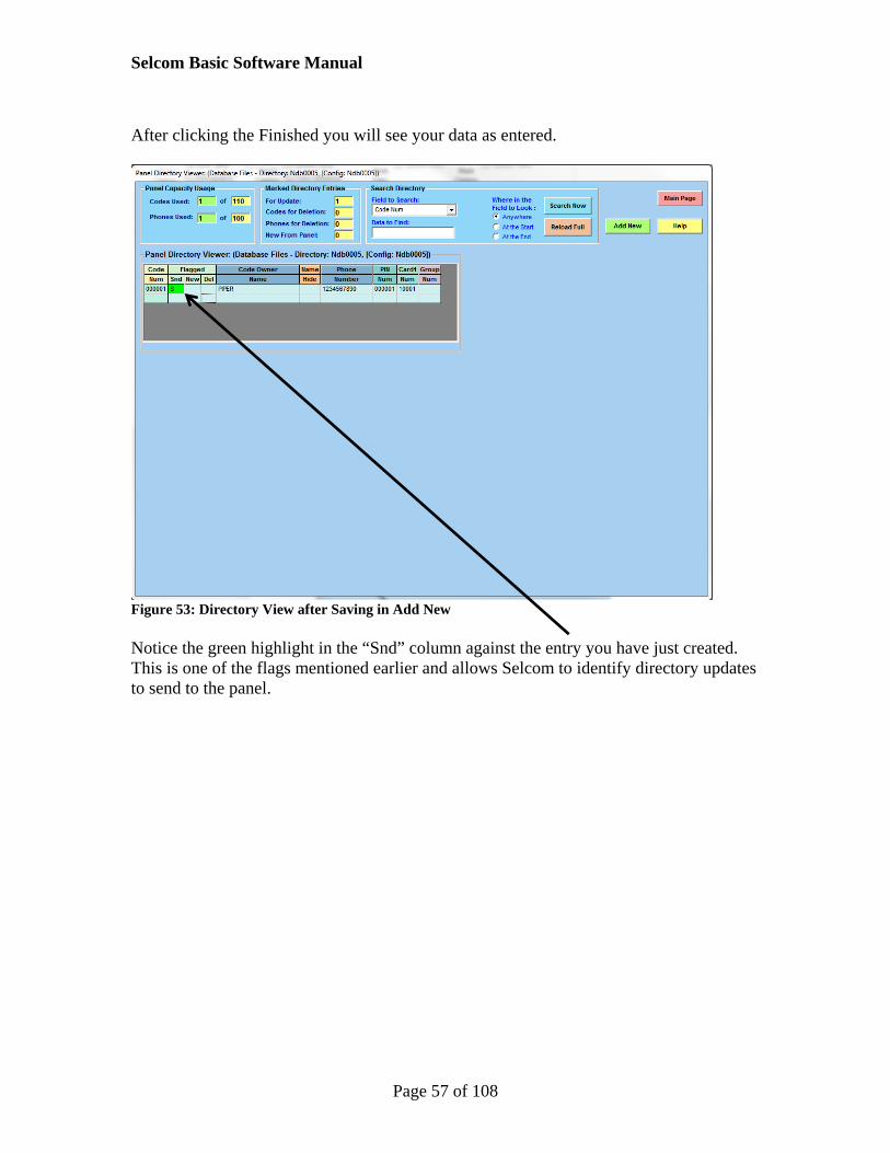
Selcom Basic Software Manual
Page 57 of 108
After clicking the Finished you will see your data as entered.
Figure 53: Directory View after Saving in Add New Notice the green highlight in the “Snd” column against the entry you have just created. This is one of the flags mentioned earlier and allows Selcom to identify directory updates to send to the panel.

Selcom Basic Software Manual
Page 58 of 108
3.5.5 Directory Edit Mode There are two ways to edit directory data:
1. From the editor in Add New mode, click the yellow button “Change to Edit” towards the far right bottom.
2. Click anywhere on an existing entry in the Directory Viewer. In Edit Mode, some new controls appear. These are the “Delete from Panel” checkbox, the “Mark for Delete” button, and the directory “step bar”, which in Edit Mode allows you to step one-at-a-time through the entries in your database. Notice the pink indicator has changed to “Edit Mode”.
Figure 54: Directory - Edit Mode You can change anything you want except the Code Number, which is fixed once added, as explained before. Once you have made changes, click Save Changes to save the data.

Selcom Basic Software Manual
Page 59 of 108
3.6 Sending the Directory to the Panel You are using this software is to make it easy to set up data by using your PC. However, this is only the first stage – you have to move the data over to the panel. To move i.e. send data over to the panel, we have to use the Automatic Interface screen mentioned earlier. On the Main Page, click on the Automatic Interface buttons to show the Communications screen. For our example site, we are going to send the whole directory, so in the Dir column against your new site, left click the mouse and choose “Send Whole Directory”. We could also send directory updates, but this example is just to get you going.
Figure 55: Example Send Whole Directory Click Start Comms. The software will call the panel and send the whole directory (one entry in our example). Warning – Sending Whole Directory Erases Directory Contents in Panel When sending a Whole Directory, any existing directory within the panel is ERASED completely and is NON-RECOVERABLE. If you are not sure, select Send Directory Updates only instead. A PROMPT cannot be provided because it would halt all calls.

Selcom Basic Software Manual
Page 60 of 108
The final results of sending in our example are shown below.
Figure 56: Results of Example Send Whole Directory
3.6.1 The Progress indicator and Comms Log Files During a call, this is the most important indicator of how the call is going. At the end of the call the information is still there so that you can scroll up and down to view the progress. As a rough breakdown, the Progress Indicator lets you know What panel is being called The method used to call the panel Whether the call is connected Panel firmware version Stages of the call Call status (success or failure) If an error occurred, the error number The CommsLog filename under which the information in the box has been saved
(look for “Saving CommsLog to: ….) You can scroll up and down, and left and right, to see the contents of the box This information is useful as a confirmation but also very helpful if needed during a tech support call to help identify a problem.

Selcom Basic Software Manual
Page 61 of 108
Each Comms Log file is saved as a text file (“.txt”) to the Selcom working folder “…SES\Selcom\CommsLog\”, and the filename is made up of “CommsLog” appended by a date and time stamp e.g. “CommsLog 20110909153000.txt”. The format for the stamp is YYYYMMDDhhmmss, so in the example shown, the Comms Log file was saved on 9th Sept 2011 at 15:30 precisely (00 seconds). 3.7 Call Status Colors A brief outline of the colors on the Call Table during calling is listed below.
White – selection during editing of tasks and schedules Yellow – call in progress Red – indicates that the call for that particular unit failed for some reason. Check
the progress indicator. Green - indicates that all of the tasks for that particular line were completed
successfully. The colors are applied on the current line being called. This means that if the user changes the call table during calling, the final status colors (red and green) could be replaced with white. Note that when scheduling is being used, failed calls will be re-attempted within the scheduled calling period. In this case the status colors will change each time a panel is called. 3.8 A Look Back on the Introduction and Quick Start In the Introduction, we discussed Differences between TECs and CATs Differences between Selcom Premium and Selcom Basic Concepts relating to visitor access such as phones, pins and cards A brief outline of what scheduling and pin/card validity periods mean
After software installation in section 2, the quick start used a kind of tutorial to get the software to help us set up the panel: How to add a new panel (or site) How to view the directory How to add a new directory entry How to set the password and unit ID (ring count) for single units How to send the new directory information to a panel
There are many other functions available, but these are covered more formally in the remainder of this manual.

Selcom Basic Software Manual
Page 62 of 108
4 Software Reference 4.1 Displaying the Communications Page The Communications page on first entry is shown below. Note that details of the panel selected on the Main page are now displayed on a yellow highlighted line or “entry” in the “Call Table” area. Each entry has “fields” whose meaning is described by the different column titles e.g. “Location” and “ID”.
Figure 57: Communications Page – Initial Entry A line of large buttons at the top of the page, available in Selcom Premium only, provide functions to assist with communications setup and are discussed in the Selcom Premium manual. The button to return a user to the Main Page is at far top right of the button line. The Call Table, below the button line, is the cornerstone of the Selcom and is used to setup panels and communications tasks (“Session Tasks”). Each row in the Call Table represents a panel with which you wish to communicate to send or receive data. Below that lies the Communications Overview which is used to start, stop and monitor calling progress. Details of this pane will be discussed later. Note that Call Scheduling is only available in Selcom Premium.

Selcom Basic Software Manual
Page 63 of 108
Referring to the figure above, the Call Table is divided into columns, each with a two-line header or title. Each column heading and purpose is shown in the following table. Call Table Column Headings Top Row Heading
2nd Row Heading
Function or Meaning How Assigned
Panel
Location The user-assigned name given when the panel/location was created
Data for these columns is loaded
when a panel is added to the Call
Table. If these fields need to be changed, then the user should exit
the Comms. page and edit the
settings in the Edit Panel Data or
System Settings pages
ID The Ring Count i.e. the number of rings that will occur before the panel answers when called by a modem
MUI (If Set)
MUI Name Specifically for Multiple Unit configurations, each panel can be assigned its own name to help distinguish it from others (user benefit only).
ID If assigned, the MUI ID is often different to Panel ID Similar to Panel ID, and. The MUI ID applies only to Multiple Unit configurations where several panels share the same telephone line. By setting unique MUI ID values, the user controls the order in which panels answer the modem.
Database File
Config. This is the database file containing panel configuration settings. In Selcom Basic this is the same as the “Dir.” Database File.
Dir. This is the database file containing panel directory data. In Selcom Basic this is the same as the “Config.” Database File.
Will Connect To Panel Using This is the communications method that is currently setup for this panel.
Assigned Schedule Feature unavailable in Selcom Basic The user edits
these fields using pop-up menus
available when left and/or right-
clicking the mouse on a Call Table
entry
Assigned Session Tasks
Dir. Get, Send Full and Send Update options Config. Get and Send options Log Get and Clear After Get options Misc. Send Test, Sleep and Date/Time Update
options
Session Overall Results
Lists basic success/failure for each Session Task
Written by Selcom during calls
Figure 58: Call Table Column Headings and Meanings

Selcom Basic Software Manual
Page 64 of 108
As can be seen from the figure in the “Quick Get Directory Example below”, the columns to the left of the Call Table (the titles are in various shades of grey) are filled in by Selcom from information stored in the panel database. This information is provided to allow the user to confirm that panel details and communication methods are as expected. The real flexibility and power of the Call Table is that users can set individual communications tasks (“Sessions”) and assign call times (Schedules) to those Sessions. However, it is not necessary to use a Schedule if you don’t want to – simply set up the session tasks and click the Start Comms button to proceed. 4.2 Quick Get Directory Example The following short example will demonstrate how to get a panel’s Directory using TCP/IP (Ethernet) communications. Starting from a successful login of Selcom, the Selcom main page is presented and allows selection of a panel from the drop-down list box. In our previous illustrations we selected a pre-created panel “My New Site 2” and then clicked on the “Automatic Interface Screen” button. This enters the Communications page shown below.
Figure 59: Communications Screen Showing Left-Click Dir Options

Selcom Basic Software Manual
Page 65 of 108
In Selcom Basic, you can only enter the automatic communications screen having first selected a panel on the main page. Once in the communications screen, we can now set it to get the Directory from the panel. To do this, we will select the desired task from a mouse menu. However, as mouse menus in Selcom are context-sensitive, we must first move the mouse pointer to the location on the table so that left-clicking will display the menu options we need. Locate the entry on the Call Table starting with our panel location (in our example this is the yellow line that starts with “My New Site 2” at the far left). Move the mouse along the line towards the right until the mouse pointer is under the green column heading “Dir.” under the green main heading “Assigned Session Tasks”. Use the mouse left-click to display the context-sensitive menu. This menu will display various options for assigning session tasks (no screenshot available). We are interested in the 4th menu line from the top i.e. “Get Directory”. Left click this menu line to place a “G” in the field where the mouse was pointing. The result is shown below.
Figure 60: Call Table – Setup for Get Directory Once set up is complete, click the light blue “Start Comms” button in the “Current Activity” pane of the “Communications Overview” panel. Communications will immediately commence, as shown in the next figure.

Selcom Basic Software Manual
Page 66 of 108
Figure 61: Call Table When Communications Have Started Note that the Call Table line entry is a bright yellow background that signifies the panel on the current line is being called i.e. is the Active entry in the Call Table. Depending on the task(s) chosen, indicators within the Current Activity area will display relevant status or progress information. However, the most important status indicator is the Progress Display. This is the white box to the far right of the Current Activity pane. The Progress Display is useful from two main aspects. Firstly, it provides a visual listing of progress throughout the call and what issues if any were encountered. This is useful for hands-on setup and diagnostics. Secondly, and new to Selcom 7, Progress Display information for ALL sessions are saved to a communications log file, known as a “Comms Log”. Each Comms Log file is saved as a text file (“.txt”) to the Selcom working folder “…SES\Selcom\CommsLog\”, and the filename is made up of “CommsLog” appended by a date and time stamp e.g. “CommsLog 20110909153000.txt”. The format for the stamp is YYYYMMDDhhmmss, so in the example shown, the Comms Log file was saved on 9th Sept 2011 at 15:30 precisely (00 seconds).

Selcom Basic Software Manual
Page 67 of 108
At the end of a session, the Progress Display will show the steps taken to finalize the call, and at the far right of the Call Table, the “Session Overall Results” field will display the final outcome, in this case “GD OK”. “GD” means, Get Directory, so the result is telling us that the task to get the directory was completed successfully.
Figure 62: Call Table Communications Successful Completion Notice that the active entry turned green. This is also a visual indicator of success. For failures, the background will become red.

Selcom Basic Software Manual
Page 68 of 108
4.3 Selecting Communications Options for Panels
4.3.1 Selcom Basic In Selcom Basic, the Call Table is limited to one line only (or several lines that belong to a single MUI group). Limited selection of communications actions is done by clicking on a row under one of the three task columns in the Call Table:
Directory Config. Log
Only left-click mouse actions are supported in the Call Table in Selcom Basic. 4.4 Selcom Basic Mouse LEFT-CLICK Menu Lists Left Click in a Directory Column
Get Directory Toggles with Remove Get Directory Send Whole Directory Toggles with Remove Send Whole Directory Send Directory Updates Only Toggles with Remove Send Directory Updates Only Clear Directory Updates Flag Toggles with Remove Clear Directory Updates Flag
Left Click in a Config. Column
Get Configuration Toggles with Remove Get Configuration Send Configuration Toggles with Remove Send Configuration
Left Click in the Get Log Column
Get Log Toggles with Remove Get Log Acquire Raw Log Toggles with Acquire Raw Log
Mouse LEFT-CLICK
Menu Options – DIRECTORY Column Only** Mouse Menu Options Displayed What it Does Get Directory Remove Get Directory
Toggles* the “Get Directory” option only for that row. Displays “G” in field when added.
Send Whole Directory Remove Send Whole Directory
Toggles* the “Send Whole Directory” option for that row. Displays “S” in field when added.
Send Directory Updates Only Remove Send Directory Updates Only
Toggles* the “Send Directory Updates Only” option for that row. Displays “U” in field when added.
Clear Directory Updates Flag Remove Clear Directory Updates Flag
Toggles* the “Clear Directory Updates Flag” option for that row. Displays “C” in field when added.
*Toggle means “to invert the current state”. For example, if a “G” is displayed then toggle will remove the “G”. **These apply only to the row clicked in the Call Table

Selcom Basic Software Manual
Page 69 of 108
Figure 63: Mouse Left-Click Directory Column Options Mouse LEFT-CLICK
Menu Options – CONFIGURATION Column Only Mouse Menu Options Displayed What it Does Get Configuration Remove Get Configuration
Toggles the “Get Configuration” option only for that row. Displays “G” in field when added.
Send Configuration Remove Send Configuration
Toggles the “Send Configuration” option for that row. Displays “S” in the field when added.
*Toggle means “to invert the current state”. For example, if a “G” is displayed then toggle will remove the “G”. **These apply only to the row clicked in the Call Table
Figure 64: Mouse Left-Click Configuration Column Options Mouse LEFT-CLICK
Menu Options – GET LOG Column Only Mouse Menu Options Displayed What it Does Get Log Remove Get Log
Toggles the “Get Log” option for that row. Displays “G” in the field when added.
Acquire Raw Log Remove Acquire Raw Log
Toggles the “Acquire Log” option for that row. Displays “A” in the field when added.
*Toggle means “to invert the current state”. For example, if a “G” is displayed then toggle will remove the “G”. **These apply only to the row clicked in the Call Table
Figure 65: Mouse Left-Click Get Log Column Options

Selcom Basic Software Manual
Page 70 of 108
5 Communications Settings 5.1 Introduction to Selcom Basic Communications Settings Communications settings can be a little confusing for new or occasional users of Selcom Basic. This is because there are various ways of connecting to a panel, and Selcom Basic has a different looking interface to that of TecBasic. To try to clarify things, we refer to two different aspects of user communications:
The Communications Method The Communications Interface
Although these might seem the same, they are not. For Selcom Basic installed on a PC, the Communications Method refers to the physical way that can be used to be connected to a panel. The possible Methods are:
Serial - An RS232 cable from the PC with a COM port directly to a panel. The COM port might be a real COM port on the back of the PC, or a USB COM port, common in today’s PCs, or a USB COM port with a USB serial adapter.
Modem - A dial-up telephone line between a PC modem and the panel. The PC may have a physical modem installed, or it may have a USB modem, common in today’s PCs. The telephone line must be either public or PBX.
TCP/IP (Ethernet) - An Ethernet network cable on a common subnet linking the PC to a NIC2 card installed on the panel.
The Communications Interface can be thought of as what the interface looks like to the user when the software is communicating with a panel. The possible Interfaces are:
Menu-Driven - A simple menu–driven interface which allows the user to set discrete changes to the panel configuration or directory.
Automatic - A non-menu interface that does not require user interaction. Instead, it provides status updates for the various stages of the communications process. This is usually used for transferring data on a regular or periodic basis, e.g. updating lots of directory entries, which will require larger data transfers
Both Interface types can be used with any Method, but how does a user know what method is being used and what interface to expect? The answer is actually quite simple. For each panel, information about how to communicate with your panel (i.e. the Method) can be entered using the Edit Panel screen and then stored in the database for that panel e.g. dial-up telephone numbers, serial ports and IP addresses. However, only one method can be selected at a time. This becomes the method used at the current time and is currently selected from an option button on the Edit Panel screen. The Communications Interface, however, is chosen by the user when sending or getting information from a panel, and can be different every time, as needed.

Selcom Basic Software Manual
Page 71 of 108
Generally, the interface is selected from the Communications Submenu, or, (if the user expects to use the Automatic interface) by clicking the Automatic Interface button. 5.2 Selcom Basic Ethernet (TCP/IP) Capability Selcom Basic is network capable. This means it can use TCP/IP (Ethernet) to communicate with panels already configured with NIC2 cards and that exist on the same subnet as the PC being used for Selcom. TCP/IP Speed, Distance and MUI Comparisons TCP/IP is faster than the modem method and is comparable in speed to the serial method. However, unlike the serial method which has very strict distance limitations, TCP/IP can be unlimited in terms of distance because it can work over the world wide Ethernet network, depending on the setup of the subnet between the PC and the panel. For MUI settings, TCP/IP is more efficient than modems because TCP/IP does not require panels with low ring counts to be put to “sleep” before calling panels of higher ring counts. The ring count (MUI) system applies purely to panels sharing the same phone line and being called using a modem, and hence does not apply when the TCP/IP method is used. TCP/IP can be used to communicate with panels automatically (using the Automatic Interface). This is similar to performing automatic send and retrieve of large packets of data (e.g. full directories) in previous versions of Selcom Basic when using modem or serial methods. TCP/IP can also be used to provide menu-driven interfaces for making discrete changes to panel directories and configurations.

Selcom Basic Software Manual
Page 72 of 108
5.3 The Communications Submenu The Communications submenu allows users to select the interface they wish to use when communicating with installed panels. This submenu, a hybrid replacement of menu options in previous Selcom versions, also includes options that were introduced in Selcom 7. The options are listed in the following table.
Communications Submenu Options Automatic Interface
Performs the same function as clicking on the “Automatic Interface” button on the main page - takes users to the Communications page
Menu Driven – Direct
Presents a menu-driven interface when connected to a panel. For Selcom 7 and later versions, this kind of interface is available when using Serial, Modem and TCP/IP connections methods. See section 4.5.4.
Menu Driven – Browser (NIC Needed)
Requires a web-capable NIC2 card and TCP/IP (Ethernet) connection. Presents a menu-driven interface when connected to a panel using your browser. See section 4.5.5.
Find Ethernet Panels (NIC Needed)
TCP/IP only – a small utility that finds and reports the IP addresses of panels within a specified range connected on your subnet. See section 4.3.
Figure 66: Communications Submenu Options Previous Selcom Versions – “Terminal” Interface In previous versions, the “Terminal” menu option connected Selcom to a panel in a way that presented the user with a menu-driven interface, and generally this interface simulated the legacy VT100 Terminal. The “Terminal” menu option connected to a panel using either the Serial or modem communications methods only, depending on the database configuration set for that panel. In Selcom 7 and later versions, this terminology is replaced by “Menu-Driven” to more accurately reflect its functionality.

Selcom Basic Software Manual
Page 73 of 108
5.3.1 Submenu Option: Menu-Driven - Direct Menu-driven interfaces provide users with the ability to make discrete changes to the setup (configuration) or directory of a panel. When selected, this menu option uses the TCP/IP, modem or serial methods to connect to a panel, depending on the panel’s database settings in Edit Panel. Please see the Selcom Software Users’ Manual for details on using this method when connecting with a modem or serially. For TCP/IP, the connection page looks similar to but is not identical to the modem/serial page, and instructions to connect are as follows. Warning – Panel Password Needed You will be asked for the panel password when connecting. If you do not know it, go to the System Settings screen – click the red telephone button - and record the password before proceeding.)
1. On the main page, select a panel for which TCP/IP communications method has been selected in Edit Panel.
2. Click on the Communications submenu option “Menu Driven – Direct”. This will show the following page:
Figure 67: Menu Driven – Direct - TCP/IP Method

Selcom Basic Software Manual
Page 74 of 108
3. Click on the “Connect” button in the TCPIP Connection pane. The status to the right of this button should display “Connected” and turn a light blue color.
4. Click on the large blue area to see blinking cursor (vertical white line) in the top left corner of the blue area).
5. Once you see the cursor flashing, press the “Esc” button on your PC keyboard. (Note: if you click off the blue area or go to a different application or page, you will need to click on the blue area again before pressing the “Esc” button otherwise it will not be detected.) You will then see “PASSWORD” displayed:
Figure 68: Menu Driven – Direct - TCP/IP Method, After Connect and Escape, Requesting Password
6. At this point you must type in the password of the panel you obtained from
System Settings.

Selcom Basic Software Manual
Page 75 of 108
7. Once the password has been entered, you will see a menu displayed from which to make your selections, and an example is shown below. However, please note that different panels with different firmware revisions can display different menus, depending on the options available. Please consult your panel’s owner manual for more information.
Figure 69: Menu Driven – Direct - TCP/IP Method, Main Menu Example
8. Once you have finished with the interface, press the Esc button on the keyboard to tell the panel you have finished. This will return the panel to operating mode and allow it control access as intended. After a short delay you will see a message appended to the current display: “EXIT PROG. MODE FROM SERIAL” with a date and time attached. There may also be a second “EXIT PROG. MODE” message with date and time. Both messages are normal and there is no cause for concern about the use of the word “serial”. This is because the NIC2 provides the TCP/IP functionality but behaves like a serial connection from the perspective of the panel.

Selcom Basic Software Manual
Page 76 of 108
Figure 70: Menu Driven – Direct - TCP/IP Method, Escape Pressed
9. Once the Exit message(s) have been displayed, click the Disconnect button. The TCP/IP Connection pane status should show “Closed” with a grey-blue background as in the following figure.
10. It is now safe to click the window close (X) at the top right of the page to return to the main menu.

Selcom Basic Software Manual
Page 77 of 108
5.4 Browsing to Web-Enabled NIC2 Cards Selcom now includes the ability to use your browser to link directly to a web-enabled NIC2 card. Web-Enabled NIC2 Cards These cards have web pages loaded into the firmware that are additional to the configuration pages shipped with previous NIC2 cards. If in doubt about which NIC2 card is installed in your panel, please consult your dealer. TCP/IP Ethernet Connection for Browsing to Web-Enabled NIC2 Cards To browse to web-enabled NIC2 cards, you must also have TCP/IP Ethernet connection between the PC with Selcom 7 or later installed and the NIC2 card i.e. they must be able to “see” each other over the network on which they are connected. There are many different configurations for network setup. Please consult your network administrator and/or dealer for assistance with this topic. Assuming that a web-enabled NIC2 is installed on your panel and that correct TCP/IP network connectivity exists between that NIC2 card and your Selcom 7 PC, there are two ways to browse to your panel: Using the Selcom menu option “Menu Driven – Browser (NIC Needed)” option, or, Directly using a browser without using Selcom at all. To use the first option (from within Selcom), you must have setup the TCP/IP connection information in Panel Edit. This is exactly the same information as required for setting up TCP/IP automatic communications. If in doubt please consult your dealer. To use the second option (opening a web page without using Selcom), you must have setup the TCP/IP connection information in Panel Edit to hand. This is exactly the same information as required for setting up TCP/IP automatic communications. If in doubt please consult your dealer.

Selcom Basic Software Manual
Page 78 of 108
1. When setup is complete and you are ready, click the Communications menu option “Menu Driven – Browser (NIC Needed)”. If you are using Selcom (option 1 above), the browser will open directly to the correct web page as in the next figure. However, if you are using your browser directly without Selcom (option 2 above), you will need to type the URL information manually into the URL box. In the example shown, this NIC2 card’s IP address is 10.0.0.89, so its URL is:
http://10.0.0.89.index.html
You would substitute our example IP of 10.0.0.89 with your correct IP address.
Figure 71: Browsing to a Web-Enabled NIC2
2. Your choices are now between either using the NIC2 configuration utility or connecting to the SES Panel. NIC2 configuration is a separate utility outside the scope of this discussion, so please click on “Connect to SES Panel”. You will see the following page.

Selcom Basic Software Manual
Page 79 of 108
Figure 72: Browsing to a Web-Enabled NIC2 - Opening Page
3. Note the instruction towards the top of the web page that states “Click the ‘Type Here’ box, then press Esc to Start”. The “Type Here” box is the white box at the bottom the page. The text “Type Here >>>” is just to the left of that box.
4. To connect with the panel, click in the white box so that the vertical cursor line
flashes inside the box. You may have to click more than once to do this. Once the cursor is flashing inside the white box, press the Esc button on your keyboard and wait for a couple of seconds until “PASSWORD” is displayed. You may have to press Esc more than once, waiting each time.
5. When “PASSWORD” is displayed, type in either the 6-digit or 3-digit password.
If successful, this will present you with either the full Main Menu, or the limited menu depending on whether you logged in with 6-digits or 3-digits respectively. Below is an example screen shot when logging in with the full menu.

Selcom Basic Software Manual
Page 80 of 108
Figure 73: Browsing to a Web-Enabled NIC2 - Panel Main Menu Example All keyboard entries from this point will be typed into the “Type Here >>>” text box.
To locate instructions on the Terminal Mode menus and how to use them, please refer to page 50 onwards of the CAT or TEC user manual. Page 50 instructs how to connect in Terminal mode, but pages 51 et al list the menu options and provide usage examples. If you don’t have one available, product Manuals can be found at the SES website:
http://www.selectses.com/products/products/software/

Selcom Basic Software Manual
Page 81 of 108
6. When you have finished a session, you can press the Esc key at any time. After pressing the Esc key, there will follow a short delay of about 2-3 seconds after which you will see something similar to the following screen:
Figure 74: Browsing to a Web-Enabled NIC2 - Closing Session If you waited for a period, the panel will have timed-out your connection, in which case you will also see the menu you were in, followed by the above message. If you wish to reconnect at this time, simply follow the instructions from step 1) again. Warning Once you have finished the browser session, please navigate away from the NIC2 IP address or close the browser tab or window completely. Not doing so will prevent any other connection being made, e.g. automatic communications with Selcom Premium or Selcom Basic, or communicating from another PC.

Selcom Basic Software Manual
Page 82 of 108
This requires that the user manually types the IP address of the NIC2 card into the browser’s internet address (URL) textbox. When using a Selcom menu option to link using the PC default browser (must have a web-enabled NIC2 installed on the panel). This uses the database information to get the IP address of the NIC2 card.

Selcom Basic Software Manual
Page 83 of 108
5.5 Communications Sessions
5.5.1 About Call Table Operations As the software works through its Call List, (in Selcom Basic this would be limited to a short list of MUI panels), by design it performs the required send and retrieve tasks (“sessions”), without asking questions of the user. Instead, an overall results field for each panel called is created on-the-fly at the far right of the Call Table. Previous Selcom Versions – “Get” and “Send” Actions In previous versions, Get and Send were treated as the primary focus for actions. “Get” options were limited to Get Directory, Get Configuration and Get Log. “Send” options were limited to Send Directory, Send Directory Updates and Send Configuration Updates. Instead, session details are written to the Current Activity pane at the lower right of the page. At the end of each panel session, the pane details are saved automatically as a communications log with the date and time embedded into the file name.
5.5.2 Callable and Non-Callable Panels You will notice that on first entry into the Communications page, the StartComms button is disabled. This is because no tasks have yet been assigned to the panel in the Call Table. When a task has been assigned, the StartComms button becomes enabled. The panels with assigned tasks are said to be “Callable”. Panels without assigned tasks are said to be “Non-Callable”, because if there are no tasks assigned to a panel there is no point in calling it, even though the panel is listed on the Call Table. These terms will be used in later discussions.
5.5.3 Starting a Communications Session You can start the communications process when:
The Call Table has at least one entry (i.e. a row with a panel name); and, At least one communication action has been set e.g. Get Directory. You don’t
have to set an action for each row – only one action needs to be setup for the entire table.
Once these criteria have been met, the “Start Comms” button in the Current Activity frame will be enabled.

Selcom Basic Software Manual
Page 84 of 108
5.5.4 Check Communications Prior to Starting Before you start, note that the panel named in the “Location” column will be called using the method shown in the “Comms Info” column. It is useful to review this for all rows before starting because there may have been changes to your PC hardware configuration. The most common relevant to Selcom occur when
Users upgrade from one PC to another USB modems are used instead of internal PC modems USB serial ports are used instead of the direct Serial ports e.g. COM1 or COM2
Once you are ready, click the “Start Comms” button. As soon as this is done, the first row containing a communications action will be highlighted gold, and will continue with this highlight color until the communication with that panel is complete. For each row, when communication successfully completes, the row will be highlighted pale green. If it fails, the row will be highlighted red.
5.5.5 Communication Results, Progress and Logging For each communication action, a letter code indicating the overall success so far is added to the “Results” column in the Call Table. When all actions are completed successfully, “OK” will be appended to the letter codes in the Results column for that row. For example, a successful Send Test would show a “T” in the Advanced column, with a Results entry of “TE OK”, and the row would be highlighted pale green. Communications progress is logged in the Current Activity pane to the lower right hand side (in previous versions of Selcom the box was on the left hand side). However, in addition to the box being moved there are changes to some log entries, and most importantly, each log session is saved to a logging folder “\SES\Selcom\CommsLog”. Each saved file is a “.txt” file and its name is preceded by “CommsLog ”, followed by a unique date and time stamp, so that the file cannot be overwritten during a later session. This file serves two purposes:
a) To provide user verification of the communications process details and b) To provide an additional troubleshooting resource for SES technical support. (The
files can be emailed to SES if requested. (Selcom Premium and Basic versions.) Aside from starting communications, when Start Comms is clicked, several other things happen. In the Current Activity frame:
The Stop Call and Stop All buttons are visible and enabled The Start and Stop Schedule buttons are visible and disabled

Selcom Basic Software Manual
Page 85 of 108
Current status bars in progress bar indicators are enabled, and will be updated from time to time depending on current progress
In the Communications Overview frame (to the left):
Location information including panel name, database file referenced, modules and firmware versions (both on the PC and as reported by the panel) will start to update
The Comms Status displays current communications status. The details displayed will depend upon which communication method is being used e.g. Serial, Modem or TCP/IP (Ethernet).
5.5.6 Additional Running Features – Current Activity Pane In the Current Activity pane, just next to the Progress Indicator, there are three checkboxes:
Clear List Each Call List Data Errors Ignore Update Warnings (red typeface)
The “Clear List Each Call” checkbox causes the listing to be cleared for each line called in the Call Table. No data is lost because the information in the Call Table is saved as a Communications Log (see above). The “List Data Errors” checkbox instructs the listing to display data mismatch errors, otherwise these will neither be displayed nor saved to the Communications Log. The “Ignore Update Warnings” checkbox relates to the presence of directory entries marked as updates in the current database. If this box is checked, the Call Manager will overwrite existing database directory entries in favor of those being received from a panel when performing Get Directory, and updates prepared for sending to the panel WILL BE DELETED. If this box is not checked, the presence of update markers in the database will cause the Call Manager to terminate the attempt, and the Get Directory task will not be performed, generating error number -63. This will be shown in the Progress Indicator and the corresponding communications log.

Selcom Basic Software Manual
Page 86 of 108
6 Other Functions 6.1 Changing Passwords on-the-Fly Previous versions of Selcom allowed users to change panel passwords during a Send Configuration communications session. Selcom still provides this functionality, but from the System Settings screen, which has been re-arranged for easier use and allows you to compare the old password before setting the new one on the same screen. To set the password change, select the panel location from the drop down box on the main screen, and then click on the System Settings button. This will take you to the Systems Setting screen, to the right of which is an area “Passwords and IDs”. At the bottom of this is a frame “Update to New Password” with a field “New Password”. To set the password, simply enter a new 6-digit password in the text field “New Password”, then click finished:
Figure 75: Setting-up to Change a Password on-the-Fly To ensure the new password is sent, re-select the panel from the Main Screen, go to the communications screen, set the Send Configuration option and then “Start Comms”. Note also the checkbox “Allow for Delays During Login”. This checkbox causes Selcom to adjust its settings to compensate for communications that suffer extremely long delays. However, in so doing it disables the Call Table time update feature, so set this box only on advice from your dealer.

Selcom Basic Software Manual
Page 87 of 108
6.2 Access Schedule Editor The Access Schedule Editor replaces the “Time Zone Wizard” from previous versions of Selcom. The Access Schedule is used to set up daily periods where access is allowable. This editor can be reached by clicking the icon button “Access Settings” on the main page then clicking “Edit Access Schedules” in the top left corner of the Access Settings screen. The Access Schedule Editor is displayed:
Figure 76: Access Time Schedule Editor on Entry The number of Access Time schedules available to you in Selcom Basic is 8. CATs, using Selcom Premium, have 16 schedules. Note that all of the times are grayed out and are all defaulted to 12:00. This is because until editing occurs, these time settings are ignored. If entries are non-grayed for schedule, this shows there were previous edits. As an example, we are going to edit Access Schedule 1. To do this click on the option button to the left marked “1”. This will display the time editor.

Selcom Basic Software Manual
Page 88 of 108
Figure 77: Access Time Scheduler Editor without Edits The time editor can be identified due to the large letters “Now Changing Schedule 1”. The time editor allows adjustment of the times that your schedule will be active (Start Time and Stop Time), and to determine which days the schedule is active. To edit these settings, use the drop down boxes to create the time during the day that the schedule will apply and then click on one or more days that the schedule will be relevant. A random setting example is displayed on the next page.

Selcom Basic Software Manual
Page 89 of 108
Figure 78: Edit a Schedule For holiday dates, enter the date in MMDD format where MM = the month number (e.g. 07 = July), and DD = the day format (e.g. 04 = 4th). Thus 4th July would be typed-in as 0704. Selcom automatically adds the “/” between the month and day, so you don’t need to add it yourself. Once you are satisfied with the settings, click the Save Changes button. This will save the changes you have made and then return you to the starting screen. Notice now that the changes are now listed, as in our example on the next page.

Selcom Basic Software Manual
Page 90 of 108
Figure 79: Access Time Scheduler Editor after Clicking Save Changes

Selcom Basic Software Manual
Page 91 of 108
It is possible to set the start and stop times as identical. However, when you try to do this Selcom displays an error as shown below:
Figure 80: Access Time Scheduler Editor after Attempt to Save Identical Start and Stop Times The error is highlighted in yellow and advises that the stop time must be later (by at least one minute) than the start time. When you have finished editing your access time schedules and saved the changes using the green “Save Changes” button, click on the pink “Finished” button to return to the Schedule page.

Selcom Basic Software Manual
Page 92 of 108
6.3 New Entrance Pages Selcom now has easier-to-use entrance settings pages.
6.3.1 TEC2 Entrances The following screen shots apply to TEC2 entrance settings.
Figure 81: TEC2 Entrances - 2-Reader with No Alarm Time
Figure 82: TEC2 Entrances - 2-Reader with Alarm Time Set

Selcom Basic Software Manual
Page 93 of 108
Figure 83: TEC2 Entrances - 4-Reader
6.3.2 TEC1 Entrances The following screen shot is for a TEC1 entrance settings page.
Figure 84: TEC1 Entrance Settings Note that only 2 readers can be used with the TEC1.

Selcom Basic Software Manual
Page 94 of 108
6.4 Access Settings Page The Access Settings page has been revised to help users. The principles, however, are the same.
6.4.1 Holidays Moved From Access Settings to Access Schedules Page In Selcom Basic (and Selcom Premium), holidays have been moved to the Access Schedules page as this is a time setting function.
6.4.2 About Levels and Groups The purpose of the Access Settings page is to allow site managers to define where (the entrances) and when (the times) persons are allowed to enter the premises. To do this, managers assign one or more entrances against access schedules to create “Levels”. Levels themselves can be combined to create “Groups”, where each Group is referenced by its Group number. During editing of a specific Directory entry, the Group Number is used if the site manager wishes to restrict access to the site through specific entrances and/or during specific hours. Group numbers do not have to be used - Group 0 is assumed. All persons assumed as “Group 0” have access 24/7 provided they have valid credentials (card or PIN) to enter. The Access Settings page provides Help for creating Groups from schedules and levels. The follow pages are screenshots from the Sample sites provided for reference.
6.4.3 TEC2 Access Settings
Figure 85: TEC2 Access Settings - 4-Reader

Selcom Basic Software Manual
Page 95 of 108
6.4.4 TEC1 Access Settings – Model TEC1CA Only For the TEC1 series, access settings are only available in the TEC1CA model.
Figure 86: TEC1CA Access Settings

Selcom Basic Software Manual
Page 96 of 108
6.5 Login Passwords Screen The login passwords screen is accessed from the Utilities menu on the Main Page. It can be used by managers to set up access to employees for day to day functioning. It includes a login password level system which restricts the range of actions available according to the level, where Level 1 is the highest and Level 4 is the lowest. The levels and actions allowed are tabulated below. Authority Level Settings Action Level 1 Level 2 Level 3 Level 4 Rename Files Y Create New Sites Y Y Add/Delete/Edit Passwords Y Edit Panel Data Y Change Entrance and Access Settings Y Y Y Edit System Configuration Y Y Y Edit the Directory Y Y Y Y Get Directory Y Y Y Y Get Configuration Y Y Y Y Get Activity Log Y Y Y Y View and Print Logs Y Y Use Log Utility Y User Direct Terminal Mode Y Send Directory Y Y Y Send Configuration Y Y Y Figure 87: Table of Authority Level Settings

Selcom Basic Software Manual
Page 97 of 108
The Login Passwords screen is shown below.
Figure 88: Login Passwords Screen The Managing Passwords pane to the right provides detailed help on how to add, edit and delete users, and to change passwords. The yellow indicator at the top shows how many of the 30 available login namespaces have been used so far.

Selcom Basic Software Manual
Page 98 of 108
6.6 Setting Up for Multiple Panels (MUIs) on a Single Phone Line Multiple panels can be connected to the same phone line to allow the software to program them all. This means that by dialing a single phone number, the software will be able to communicate with all of the panels sharing the line. NOTE – Multiple Unit Interface Boards MUST be Installed in Each Panel In order for each panel to answer, every panel MUST be installed with its own Multiple Unit Interface (MUI) board, otherwise the panels will not be able to answer when the software calls. The clearest advantage of using MUIs is the monetary saving when comparing the cost of MUI boards along with the installation cost of one phone line plus its monthly charge, versus the initial installation costs of a phone line plus ongoing monthly charges for each panel.
6.6.1 Comparison of Single Panel and Multiple Panel Settings To communicate with multiple panels sharing the same phone line, SES products utilize Ring Counts (or Unit IDs) in a unique way, which is best understood by first looking at a single panel installation. In single panel installations, the panel answers a call by waiting for the number of ring cycles that is currently set in its memory as “Ring Count” or “Unit ID” (this can be set to a different value using the System Settings screen). For example, in our single panel example, the Ring Count or Unit ID has been set to 3, because this is the default value used when a site is created. When the software rings the panel to perform a programming task such as Get or Send, the panel detects the ringing and counts the ring cycles heard until the number of rings matches the Ring Count. The panel then answers the call, and, after connection is confirmed, the software attempts to perform its task as required, finishing by terminating the connection. By comparison, in a multiple panel installation, each panel must be able to answer a call, but not interfere with any other panel in doing so. In addition, any panel that has already answered must be prevented from re-answering. Preventing interference from other panels is achieved by setting a different Ring Count or Unit ID in each panel. For example, in a 2-panel MUI, let us suppose that panel A has a ring count of 2, and panel B has a ring count of 4. When a call is made to the phone number shared by both panels, panel A, with its Unit ID (or Ring Count) of 2 will answer first i.e. when the number of rings heard has reached 2. Panel B will not attempt to answer because its ring count of 4 is never achieved during that first call. Preventing re-answering is achieved by utilizing a unique “Sleep” command that can be sent by the software before terminating the current call to that panel. In our Panel A/Panel

Selcom Basic Software Manual
Page 99 of 108
B example, once panel A has answered, and the call task has been performed, the software sends a Sleep command before disconnecting. When the software calls again to talk to panel B, panel A is still “sleeping”. This allows the ring count to get up to 4 so that panel B can answer. The call is then connected as normal, and the software can then perform its task, sending a Sleep before terminating the call. To setup MUI calling:
Each panel must be programmed manually with a different Ring Count (Unit ID). This must be done manually either at each panel itself or using Terminal mode to connect with each panel and then setting the unit ID. Please refer to the panel’s installer manual for more information.
Each panel must be physically installed with an MUI board (see note below). Please refer to Multiple Unit Interface board installation instructions.
Within the database, use the Selcom software to identify the panel as an “MUI” (see following section)
Within the database, set the Ring Counts (Unit IDs) using Selcom (see following section)
Note – Practical Limit of Number of Panels in MUIs Technically, up to eight (8) panels can be connected on a single line. However, in practice, it has been found that four (4) is a more practical limit, with a ring count spacing of 2, 4, 6 and 8. This is because single noise spikes on the phone line can sound like a ring, and when this happens, such spikes are counted as a separate ring cycle. Separating ring count values by 2 and not starting with a ring count of ‘1’ avoids the effects of phone line spikes. Note – Sleep in Selcom Basic For Selcom Basic users, once a panel is identified as an “MUI”, the Sleep command is sent automatically at the end of each call to an MUI panel. Selcom Premium has more flexibility by allowing users to choose which panels to communicate with and whether to send a sleep command.

Selcom Basic Software Manual
Page 100 of 108
6.6.2 Using Edit Panel Data to Setup MUIs in the Panel Database To set a panel as an “MUI”, go to the edit panel page. First, ensure that the Modem option is selected. This will display the “Single or Multiple Panels” settings frame.
Figure 89: MUI Setting - Ensure Modem is Selected First Click on the “Multiple” option that is now available, then click on Edit Unit IDs.
Figure 90: MUI Setting - Select "Multiple"

Selcom Basic Software Manual
Page 101 of 108
In the list that is displayed, set the number of panels in the phone line, and the ID (Ring Count) for each. You can also change the name of each panel in the list.
Figure 91: MUI Settings WARNING – Do not forget to enter a valid phone number. In our example, we have set the Ring Count to 2. This means that only the first two IDs in the list will be used (ring counts 2 and 4). Any other settings will be ignored. Once done you can click “Hide Unit IDs” and then click Finished. NOTE –Setting MUI Ignores Unit ID/Ring Count in System Settings Page Once the “Multiple” has been selected, the ring count/unit ID stored on the System Settings page will be ignored. WARNING – Do not forget to install an MUI board in each panel. WARNING – Do not forget to set the Ring Count/Unit ID manually in each panel.

Selcom Basic Software Manual
Page 102 of 108
Once on the main page, make sure your MUI panel is selected, then click on Automatic Communications. You will see a page similar to the following. Notice the MUI Ring Counts and names in the MUI columns, and that “Sleep” in the Misc column is already set to be sent.
Figure 92: Call Table with MUI Panels, Ring Counts and Sleep By left-clicking in one of the yellow spaces in the Dir column you can add either Send Whole Directory or Send Updates. In Selcom Basic this same setting will be applied to all MUI panel rows in the Call Table. This restriction does not apply to Selcom Premium. WARNING - Do NOT add Clear Directory Updates Flags Adding Clear Directory Update Flags inside a call to send updates will automatically clear the flags before the second panel has been called, because Selcom Basic is restricted to applying the same tasks to each line in an MUI. You should perform this as a separate operation after sending all the updates. WARNING - Do NOT Send or Receive Configurations in MUIs Sending or receiving configurations will override the ID settings either in the database or panel automatically leading to subsequent confusion and possible data loss.

Selcom Basic Software Manual
Page 103 of 108
Examples of a Call Table for Send Whole Directory, and Send Directory Updates are shown separately below.
Figure 93: MUI Call Table with Send Whole Directory (S)
Figure 94: MUI Call Table with Send Directory Updates (U) Only

Selcom Basic Software Manual
Page 104 of 108
6.7 About Screen If information about the current version of either Selcom version is needed, it be accessed from Help About.
Figure 95: About Selcom Basic

Selcom Basic Software Manual
Page 105 of 108
6.8 Help and Support Screen (Dealer Information) This screen is primarily intended to allow users to identify their product and primary source of information i.e. the dealer information in the two text boxes. This may or may not be completed and is the responsibility of the dealer or the installer. Users can also access the software manual and the Supplement (this document). Both are pdf documents and can be viewed with any preferred pdf viewer. By clicking on the button “Visit the SES Web Site”, dealers can also visit the SES web site to obtain additional information to support their end users. Dealer Information can be accessed from Help Help and Support screen.
Figure 96: Selcom Basic Help and Support

Selcom Basic Software Manual
Page 106 of 108
6.9 Startup and Program Options These options can be set by the dealer or installer and are accessed from Edit Startup and Program Options. The dealer or installer should insert their contact information in the two text boxes inside the pane “Dealer Information”, as shown in our example “Acme Fencing Suppliers”.
Figure 97: Program and Startup Options with Dealer Information Entry The startup option “Don’t Show Pending Daylight Savings Time Advisory on Startup” was moved from the previous combined startup screens. The warning provides information that daylight savings time changes are imminent. The warning occurs on startup and can be turned off by clicking and placing a check mark in the checkbox. The actual warning itself is in the following section.

Selcom Basic Software Manual
Page 107 of 108
6.10 Daylight Savings Time Warning This screen is purely a warning that can be turned off either in this page or in the Program and Startup Options discussed already. The screen appears on startup before login and has the following appearance in Selcom 7:
Figure 98: Daylight Savings Time Warning Message on Startup (if Enabled) WARNING If turned off, this advisory will not appear again unless the checkbox is cleared manually.

Selcom Basic Software Manual
Page 108 of 108
6.11 Main Page Menus Some of the menu options on the main page have changed compared to previous versions. The menu options on Selcom are now as follows: File Simple Site Creator
----- Exit
Edit Edit Panel Data
----- Directory View/Edit Bulk Load Cards – PINS ----- System Settings Entrance Settings Startup and Program Options
Communications Automatic Interface
Menu Driven – Direct Menu Driven – Browser (NIC Needed)
View Show Event Log
----- Read Manual ----- View Error Number Listings
Utilities Login Passwords
----- Update Specific Database File to 7.1.0
Reports Print Directory Short By Alpha
Print Directory Short By Code ----- Print System Configuration Print Entrance Configuration
Help About Selcom Basic Help and Support

“BETTER TECHNOLOGY MAKES BETTER SYSTEMS”
Manual #: 900SELCOMBSK
12/2015
Select Engineered Systems, Inc. Hialeah, FL 33016
Website: www.selectses.com
Email: [email protected]


![SELCOM (Recambios de Puertas HIDRA 3201)[1]](https://img.dokumen.tips/doc/110x75/55cf9479550346f57ba24667/selcom-recambios-de-puertas-hidra-32011.jpg)
