Embed Size (px)
Citation preview

Naval Education andTraining Command
NAVEDTRA 12419May 19930502-LP-477-6400
Training Manual(TRAMAN)
Electronics Technician
Volume 9–Electro-Optics
DISTRIBUTION STATEMENT A: Approved for public release; distribution is unlimited.
Nonfederal government personnel wanting a copy of this documentmust use the purchasing instructions on the inside cover.
0502LP4776400

Although the words “he,” “him,” and “his” areused sparingly in this manual to enhancecommunication, they are not intended to be genderdriven nor to affront or discriminate againstanyone reading this text.
DISTRIBUTION STATEMENT A: Approved for public release; distribution is unlimited.
Nonfederal government personnel wanting a copy of this document must write to Superintendent of Documents, GovernmentPrinting Office, Washington, DC 20402 OR Commanding Officer, Naval Publications and Forms Directorate, Navy AviationSupply Office, 5801 Tabor Avenue, Philadelphia, PA 19120-5099, Attention: Cash Sales, for price and availability.

ELECTRONICS TECHNICIANVOLUME 9
ELECTRO-OPTICS
NAVEDTRA 12419
1993 Edition Prepared byETCS(SW) Linda Villareal and
ETC Allen E. Carney

PREFACE
This training manual (TRAMAN), Electronics Technician, Volume 9,Electro-Optics, NAVEDTRA 12419, and its companion nonresident training course(NRTC), NAVEDTRA 82419, are part of a planned 9-part series of TRAMANsintended to provide Navy enlisted personnel with information pertinent to theirassignments and necessary for advancement to the Electronics Technician SecondClass rate. The nine volumes planned for the series areas follows: Volume 1, Safety;Volume 2, Administration; Volume 3, Communication Systems; Volume 4, RadarSystems; Volume 5, Navigation Systems; Volume 6, Digital Data Systems; Volume 7,Antennas and Wave Propagation; Volume 8, System Concepts; Volume 9,Electro-Optics.
Designed for individual study instead of formal classroom instruction, theTRAMANs provide subject matter that relates directly to the OccupationalStandards for the Electronics Technician Second Class. The Navy Electricity andElectronics Training Series (NEETS) modules provide information that is basic toyour understanding of the material presented in these volumes. To avoid repeatingsuch basic information, these volumes refer you to the appropriate NEETS modulesand EIMB handbook. You may also be directed to review or study additionalreferences commonly found in ET workspaces or used by Electronics Technicians.You should study the referenced publications as thoroughly as you would if theywere repeated as part of the ET2 TRAMAN. The NRTCs, printed under separatecover, consist of supporting questions designed to help you study the associatedTRAMAN and referenced publications and to satisfy part of the requirements foradvancement.
This training manual and the nonresident training course were prepared by theNaval Education and Training Program Management Support Activity for the Chiefof Naval Education and Training.
1993 Edition
Stock Ordering No.0502-LP-477-6400
Published byNAVAL EDUCATION AND TRAINING PROGRAM
MANAGEMENT SUPPORT ACTIVITY
UNITED STATESGOVERNMENT PRINTING OFFICE
WASHINGTON, D.C.: 1993
i

THE UNITED STATES NAVY
GUARDIAN OF OUR COUNTRY
The United States Navy is responsible for maintaining control of thesea and is a ready force on watch at home and overseas, capable of strongaction to preserve the peace or of instant offensive action to win in war.
It is upon the maintenance of this control that our country’s gloriousfuture depends; the United States Navy exists to make it so.
WE SERVE WITH HONOR
Tradition, valor, and victory are the Navy’s heritage from the past. Tothese may be added dedication, discipline, and vigilance as the watchwordsof the present and the future.
At home or on distant stations as we serve with pride, confident in therespect of our country, our shipmates, and our families.
Our responsibilities sober us; our adversities strengthen us.
Service to God and Country is our special privilege. We serve withhonor.
THE FUTURE OF THE NAVY
The Navy will always employ new weapons, new techniques, andgreater power to protect and defend the United States on the sea, under thesea, and in the air.
Now and in the future, control of the sea gives the United States hergreatest advantage for the maintenance of peace and for victory in war.
Mobility, surprise, dispersal, and offensive power are the keynotes ofthe new Navy. The roots of the Navy lie in a strong belief in the future, incontinued dedication to our tasks, and in reflection on our heritage from thepast.
Never have our opportunities and our responsibilities been greater.
ii

CONTENTS
CHAPTER
1. Introduction to Night Vision Equipment
2. Introduction to LASERS . . . . . . . .
APPENDIX
I. References.
INDEX . . . . . . . .
. . . . . . . . . . . . . . .
. . . . . . . . . . . . . . .
iii
. . . . . . . . . . . . . . . 1-1
. . . . . . . . . . . . . . . 2-1
. . . . . . . . . . . . . . AI-1
. . . . . . . . . . . INDEX-1

SUMMARY OF THE ELECTRONICSTECHNICIAN TRAINING SERIES
This series of training manuals was developed to replace the ElectronicsTechnician 3 & 2 TRAMAN. The content is directed toward personnel workingtoward advancement to Electronics Technician Second Class.
The nine volumes in the series are based on major topic areas with which theET2 should be familiar. Volume 1, Safety, provides an introduction to general safetyas it relates to the ET rating. It also provides both general and specific informationon electronic tag-out procedures, man-aloft procedures, hazardous materials(i.e., solvents, batteries, and vacuum tubes), and radiation hazards. Volume 2,Administration, discusses COSAL updates, 3-M documentation, supply paperwork,and other associated administrative topics. Volume 3, Communication Systems,provides a basic introduction to shipboard and shore-based communication systems.Systems covered include man-pac radios (i.e., PRC-104, PSC-3) in the hf, vhf, uhf,SATCOM, and shf ranges. Also provided is an introduction to the CommunicationsLink Interoperability System (CLIPS). Volume 4, Radar Systems, is a basicintroduction to air search, surface search, ground controlled approach, and carriercontrolled approach radar systems. Volume 5, Navigation Systems, is a basicintroduction to navigation systems, such as OMEGA, SATNAV, TACAN, andman-pac systems. Volume 6, Digital Data Systems, is a basic introduction to digitaldata systems and includes discussions about SNAP II, laptop computers, and desktopcomputers. Volume 7, Antennas and Wave Propagation, is an introduction to wavepropagation, as it pertains to Electronics Technicians, and shipboard and shore-basedantennas. Volume 8, System Concepts, discusses system interfaces, troubleshooting,sub-systems, dry air, cooling, and power systems. Volume 9, Electro-Optics, is anintroduction to night vision equipment, lasers, thermal imaging, and fiber optics.
iv
CHAPTER 1
INTRODUCTION TO NIGHT VISION EQUIPMENT
Throughout the history of wars, the cover ofdarkness has provided a tactical advantage for oneforce or the other. In this chapter, we will begin witha brief explanation of how the human eye “sees”during daytime and nighttime. We will then introduceand explain the various devices used in today’smilitary to enhance the night vision capabilities ofmilitary personnel.
THE HUMAN EYE
The primary components of the eye that controlday vision and night vision are the rods and the cones,found in the retina. The retina translates light energy,absorbed by the rods and cones, into nerve impulsesto be carried to the brain by the optic nerve. The brainthen converts the nerve impulses into images.
The eyes of some animals that hunt at night andsleep in the daytime (such as the opossum) haveretinas composed almost entirely of rods; otheranimals that sleep in the nighttime (such as mostbirds) have retinas composed almost entirely ofcones.
The human eye has a retina composed of bothrods and cones.
CONES
The primary factor in both color vision and acutedaytime vision is the cones. During the day, the eyetends to rotate, to center the image nearer to the areaof the retina where the cones are most concentrated.
The center three degrees of the retina is made upentirely of cones. This area is called the fovea.
RODS
The rods, being very sensitive to low illuminationlevels, control night vision. At night, the eye switchesfrom cone vision to rod vision and becomes colorblind. Since only rods can adjust to the low-lightlevels available at night, the center three degrees ofsolid cones becomes a blind spot in the center of thefield of view.
1-1
The average field of view for the human eye isabout 80 degrees vertical by 170 degrees horizontal.
OFF-CENTER VISION
To compensate for the blind spot in the center ofthe field of view, an observer should use off-centervision. Off-center vision involves looking off to theside of the object of interest, scanning its peripheryusing short three-second movements. Three secondsallows the rods adequate stimulation time. In thedark, extra stimulation time is needed for the rods togather sufficient information to form visual images.
DARK ADAPTATION
The cones and rods are turned on and off by thesecretion of photosensitive pigments called iodopsinand rhodopsin.
Cones adapt (secrete iodopsin) very quickly tohigh-light levels. However, the rods require severalminutes to adjust (secrete rhodopsin) to low-lightlevels. In extremely dark situations, the normal eyemay require up to 40 minutes to become fullydark-adapted.
Now that we have discussed how the human eyereacts to different light levels, let’s move on toelectro-optical devices.
HISTORICAL BACKGROUND
Early efforts to remove the cover of darknessincluded the use of torches, brush fires, flares, androckets. During World War I, formal research workwas begun in the realm of night vision, but thoseefforts were limited to developing and refiningsearchlight illumination.
Research by an electronics company in the 1930’sled to development of an image tube that could beused to convert infrared images to visible displays.The military significance of this quickly becameapparent. Further development led to the productionof a small arms unit—the “Sniperscope.”
Use of the sniperscope involved pointing thedevice toward some sound heard in the darkness,
switching on the power supply, and scanning theforward area until the source of the sound was locatedor determined. Infrared rays, visible only to theoperator, were projected over the sighting area. Thereflected rays, picked up by the electronic telescope,were converted to a visible image and magnifiedaccording to the power of the telescope. Sightedobjects appeared in varying shades of green,regardless of their daylight color. Researchers chosethe color green because green light stimulates thecones without shutting down the rods. This enablesthe person using the night scope to look at a relativelybright picture without losing any night vision.
Night vision capabilities proved to be particularlyeffective in combatting enemy infiltration tacticsconducted during periods of darkness. However, amajor problem with the use of infrared instrumentswas that the user could be readily spotted by a foewho also was using infrared instruments or detectionequipment. To combat this problem, researchersdeveloped passive devices, devices that only receivedlight from a source and amplified that light to producea picture on a screen. In the following sections, wewill discuss both active and passive devices that are inuse today.
ELECTRO-OPTICAL DEVICES
All electro-optical devices use some source o fpower to produce an image of an object throughillumination, amplification, or thermal imaging.These devices contain electronic components as wellas electro-optical components such as light emittingdiodes, image intensifier tubes, and lasers. Examplesof such devices are night vision goggles and riflesights, laser range finders, markers and designators,and forward looking infrared receivers.
The night vision department of the Naval SurfaceWarfare Center, located in Crane, Indiana, is thecentral point of contact for all electro-opticalequipment used in the Navy.
BATTERIES FOR NIGHT VISIONEQUIPMENT
Every night vision device uses a battery toproduce image intensification. The battery suppliesvoltage that accelerates electrons across an imageintensifier tube. Various types of batteries are used inNavy and Marine Corps night vision equipment.
Alkaline batteries are inexpensive and readilyavailable. However, their service life is the shortest ofall the battery types.
Mercury batteries were used as power sources inearlier night vision equipment but, due to ecologicalproblems, are now being removed from service.
Nickel-cadmium batteries are used primarily fortraining since they require down time whilerecharging.
Lithium batteries provide the longest service lifeat temperatures above 15 degrees Fahrenheit.Because of high performance, this type of battery isused when possible. These batteries must be approvedby the Navy Lithium Safety Review Board beforeapproval for service use.
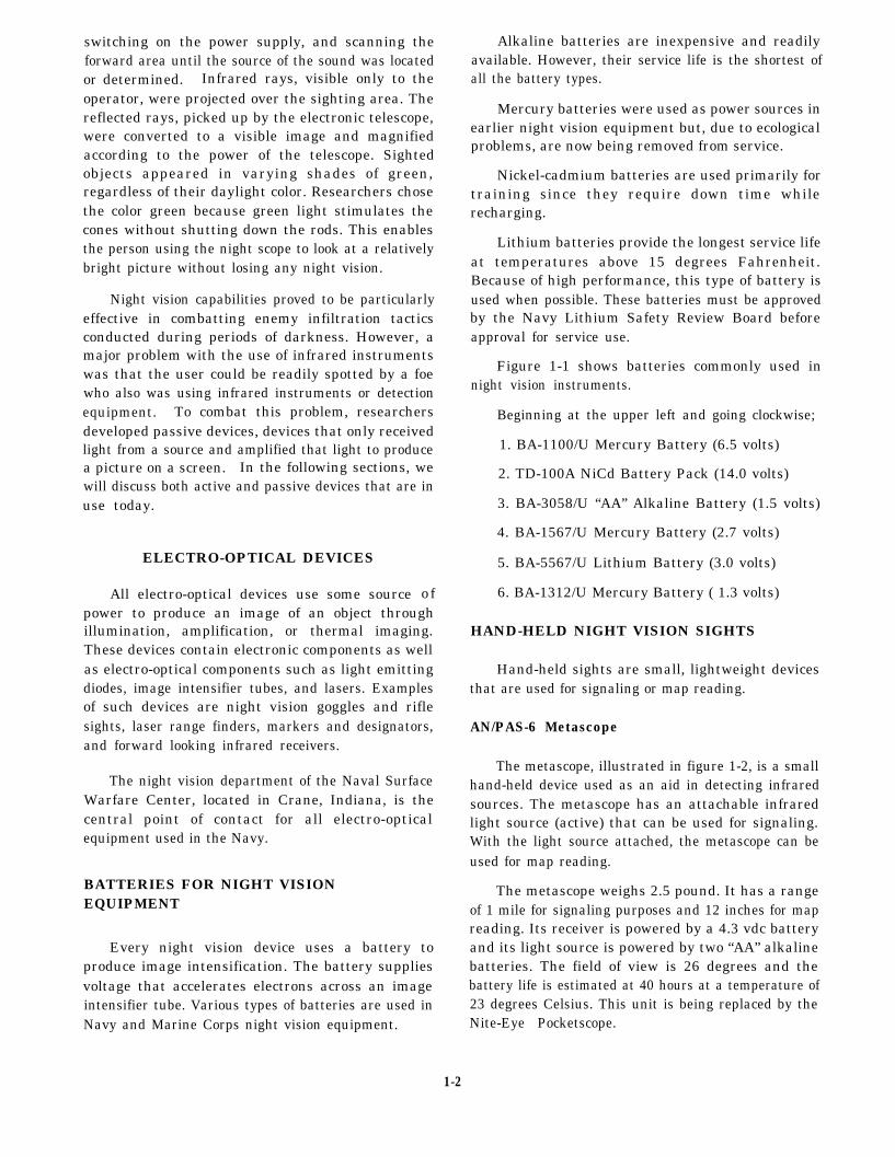
Figure 1-1 shows batteries commonly used innight vision instruments.
Beginning at the upper left and going clockwise;
1. BA-1100/U Mercury Battery (6.5 volts)
2. TD-100A NiCd Battery Pack (14.0 volts)
3. BA-3058/U “AA” Alkaline Battery (1.5 volts)
4. BA-1567/U Mercury Battery (2.7 volts)
5. BA-5567/U Lithium Battery (3.0 volts)
6. BA-1312/U Mercury Battery ( 1.3 volts)
HAND-HELD NIGHT VISION SIGHTS
Hand-held sights are small, lightweight devicesthat are used for signaling or map reading.
AN/PAS-6 Metascope
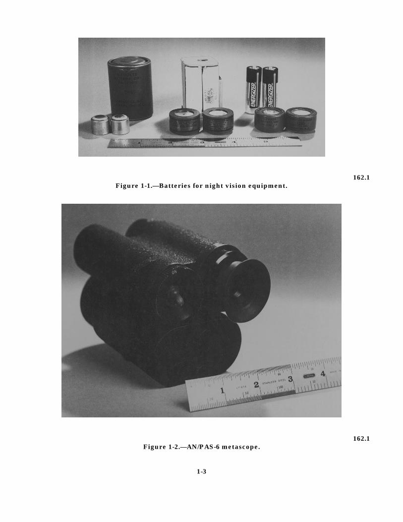
The metascope, illustrated in figure 1-2, is a smallhand-held device used as an aid in detecting infraredsources. The metascope has an attachable infraredlight source (active) that can be used for signaling.With the light source attached, the metascope can beused for map reading.
The metascope weighs 2.5 pound. It has a rangeof 1 mile for signaling purposes and 12 inches for mapreading. Its receiver is powered by a 4.3 vdc batteryand its light source is powered by two “AA” alkalinebatteries. The field of view is 26 degrees and thebattery life is estimated at 40 hours at a temperature of23 degrees Celsius. This unit is being replaced by theNite-Eye Pocketscope.
1-2
162.1Figure 1-1.—Batteries for night vision equipment.
162.1Figure 1-2.—AN/PAS-6 metascope.
1-3
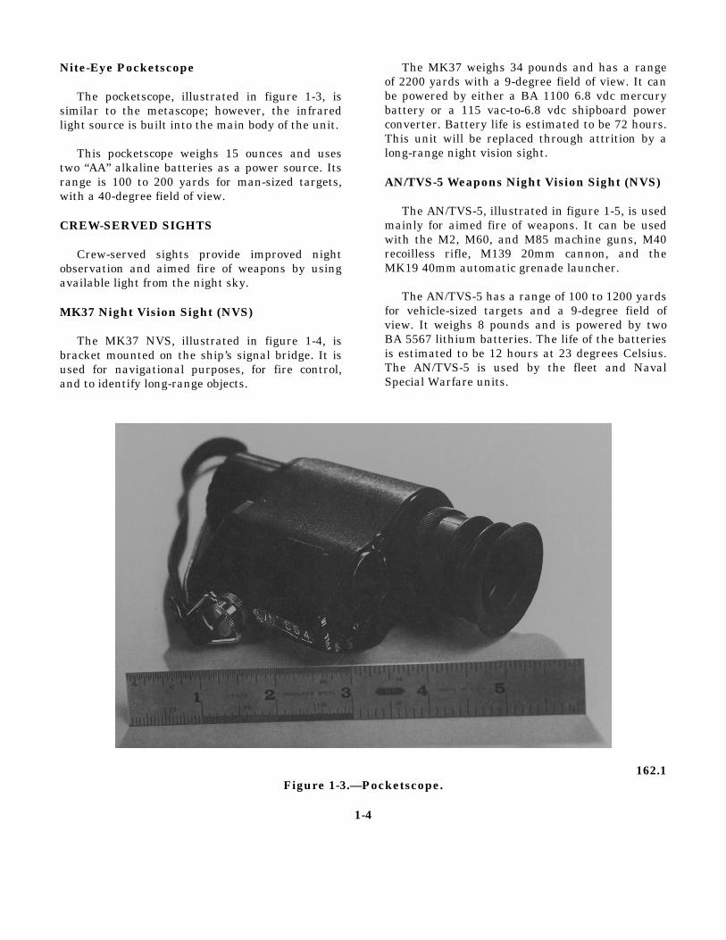
Nite-Eye Pocketscope
The pocketscope, illustrated in figure 1-3, issimilar to the metascope; however, the infraredlight source is built into the main body of the unit.
This pocketscope weighs 15 ounces and usestwo “AA” alkaline batteries as a power source. Itsrange is 100 to 200 yards for man-sized targets,with a 40-degree field of view.
CREW-SERVED SIGHTS
Crew-served sights provide improved nightobservation and aimed fire of weapons by usingavailable light from the night sky.
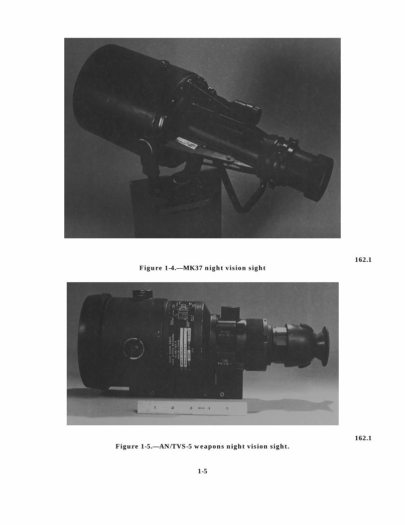
MK37 Night Vision Sight (NVS)
The MK37 NVS, illustrated in figure 1-4, isbracket mounted on the ship’s signal bridge. It isused for navigational purposes, for fire control,and to identify long-range objects.
The MK37 weighs 34 pounds and has a rangeof 2200 yards with a 9-degree field of view. It canbe powered by either a BA 1100 6.8 vdc mercurybattery or a 115 vac-to-6.8 vdc shipboard powerconverter. Battery life is estimated to be 72 hours.This unit will be replaced through attrition by along-range night vision sight.
AN/TVS-5 Weapons Night Vision Sight (NVS)
The AN/TVS-5, illustrated in figure 1-5, is usedmainly for aimed fire of weapons. It can be usedwith the M2, M60, and M85 machine guns, M40recoilless rifle, M139 20mm cannon, and theMK19 40mm automatic grenade launcher.
The AN/TVS-5 has a range of 100 to 1200 yardsfor vehicle-sized targets and a 9-degree field ofview. It weighs 8 pounds and is powered by twoBA 5567 lithium batteries. The life of the batteriesis estimated to be 12 hours at 23 degrees Celsius.The AN/TVS-5 is used by the fleet and NavalSpecial Warfare units.
162.1Figure 1-3.—Pocketscope.
1-4
162.1Figure 1-4.—MK37 night vision sight
162.1Figure 1-5.—AN/TVS-5 weapons night vision sight.
1-5
INDIVIDUAL-SERVED SIGHTS
Individual-served sights also provide improvednight observation and aimed fire of weapons byusing available light from the night sky. Theprimary difference between these sights and crew-served sights is that these sights are mainlymounted on hand-held weapons.
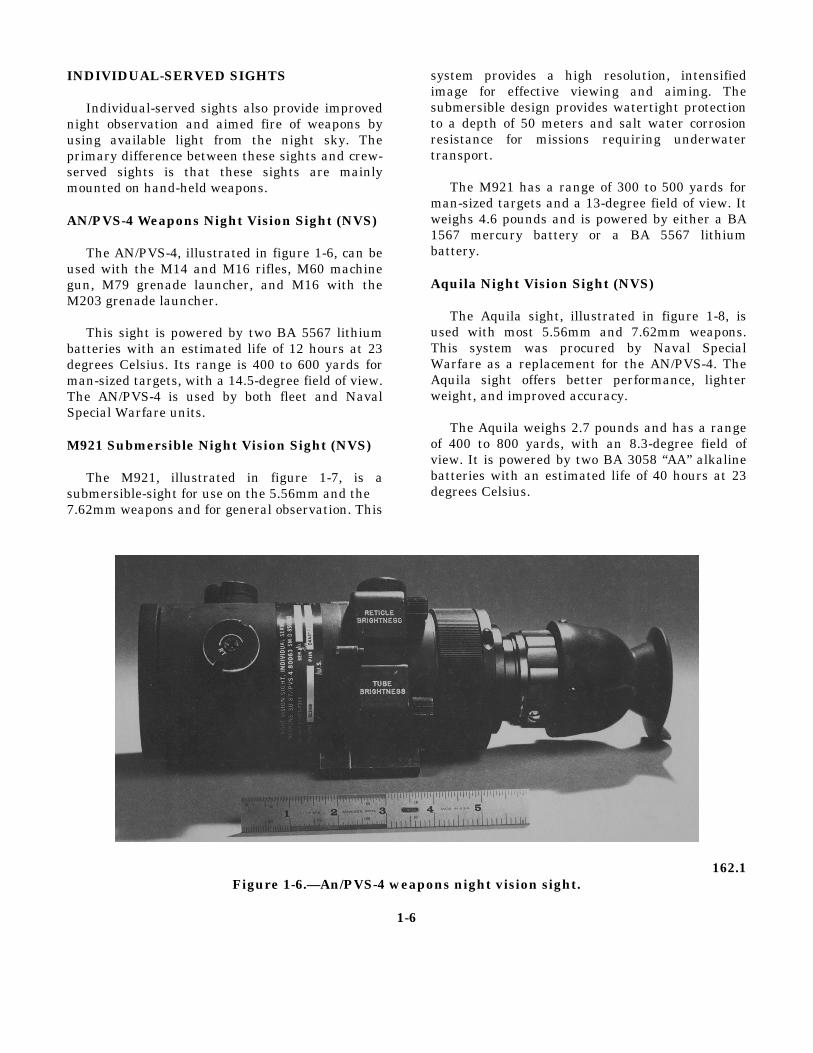
AN/PVS-4 Weapons Night Vision Sight (NVS)
The AN/PVS-4, illustrated in figure 1-6, can beused with the M14 and M16 rifles, M60 machinegun, M79 grenade launcher, and M16 with theM203 grenade launcher.
This sight is powered by two BA 5567 lithiumbatteries with an estimated life of 12 hours at 23degrees Celsius. Its range is 400 to 600 yards forman-sized targets, with a 14.5-degree field of view.The AN/PVS-4 is used by both fleet and NavalSpecial Warfare units.
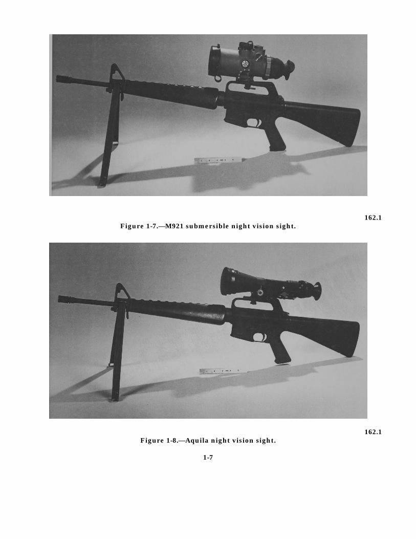
M921 Submersible Night Vision Sight (NVS)
The M921, illustrated in figure 1-7, is asubmersible-sight for use on the 5.56mm and the7.62mm weapons and for general observation. This
system provides a high resolution, intensifiedimage for effective viewing and aiming. Thesubmersible design provides watertight protectionto a depth of 50 meters and salt water corrosionresistance for missions requiring underwatertransport.
The M921 has a range of 300 to 500 yards forman-sized targets and a 13-degree field of view. Itweighs 4.6 pounds and is powered by either a BA1567 mercury battery or a BA 5567 lithiumbattery.
Aquila Night Vision Sight (NVS)
The Aquila sight, illustrated in figure 1-8, isused with most 5.56mm and 7.62mm weapons.This system was procured by Naval SpecialWarfare as a replacement for the AN/PVS-4. TheAquila sight offers better performance, lighterweight, and improved accuracy.
The Aquila weighs 2.7 pounds and has a rangeof 400 to 800 yards, with an 8.3-degree field ofview. It is powered by two BA 3058 “AA” alkalinebatteries with an estimated life of 40 hours at 23degrees Celsius.
162.1Figure 1-6.—An/PVS-4 weapons night vision sight.
1-6
162.1Figure 1-7.—M921 submersible night vision sight.
162.1Figure 1-8.—Aquila night vision sight.
1-7
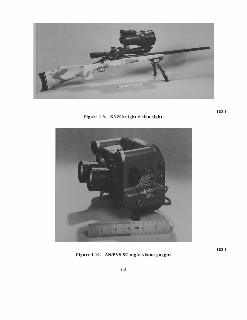
162.1Figure 1-9.—KN200 night vision sight.
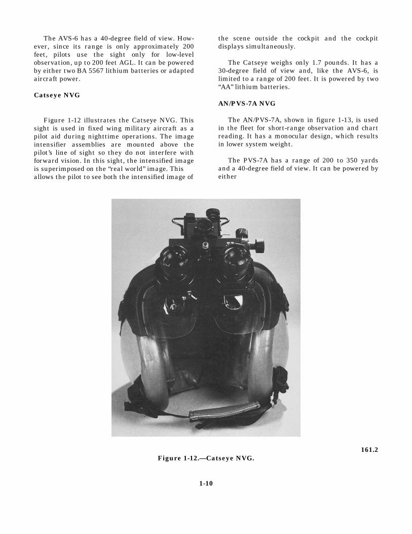
162.1Figure 1-10.—AN/PVS-5C night vision goggle.
1-8

KN200 Night Vision Sight (NVS)
The KN200 NVS, illustrated in figure 1-9, is alightweight sight adapted by Naval SpecialWarfare forces for use with a 10X day scope. Itmay also be used with currently fielded laserrange finders.
The KN200 has a 10-degree field of view and arange of 400 to 800 yards. It can be powered byeither two BA 3058 “AA” alkaline batteries or two“C” alkaline batteries.
NIGHT VISION GOGGLE (NVG)
The night vision goggle (NVG) allows the userto perform tasks such as reading, patrolling,walking, short-range observation, and mobileequipment operation. It can also be used withlaser aiming devices for off-hand shooting.
AN/PVS-5C NVG
The AN/PVS-5C, illustrated in figure 1-10, isthe latest in the PVS-5 series. It is fairlylightweight and is held to the user’s face by rubberstraps. Instructions for donning the NVG arepermanently mounted on the side of the unit.
The AN/PVS-5C has a range of 200 to 300yards for man-sized targets, a 40-degree field ofview, and is powered by a BA 5567 lithium batteryor two BA 3058 “AA” alkaline batteries.The AN/PVS-5C NVG is scheduled to be replacedby a new configuration, the AN/PVS-5D.
AN/AVS-6 NVG
The AN/AVS-6, illustrated in figure 1-11, is anAviator’s Night Vision System (ANVIS) providingthe user with improved night vision. This unitenables the user to pilot rotary wing aircraft or todrive high-speed ground vehicles.
162.1Figure 1-11.—AN/AVS-6 NVG, ANVIS
1-9
The AVS-6 has a 40-degree field of view. How-ever, since its range is only approximately 200feet, pilots use the sight only for low-levelobservation, up to 200 feet AGL. It can be poweredby either two BA 5567 lithium batteries or adaptedaircraft power.
Catseye NVG
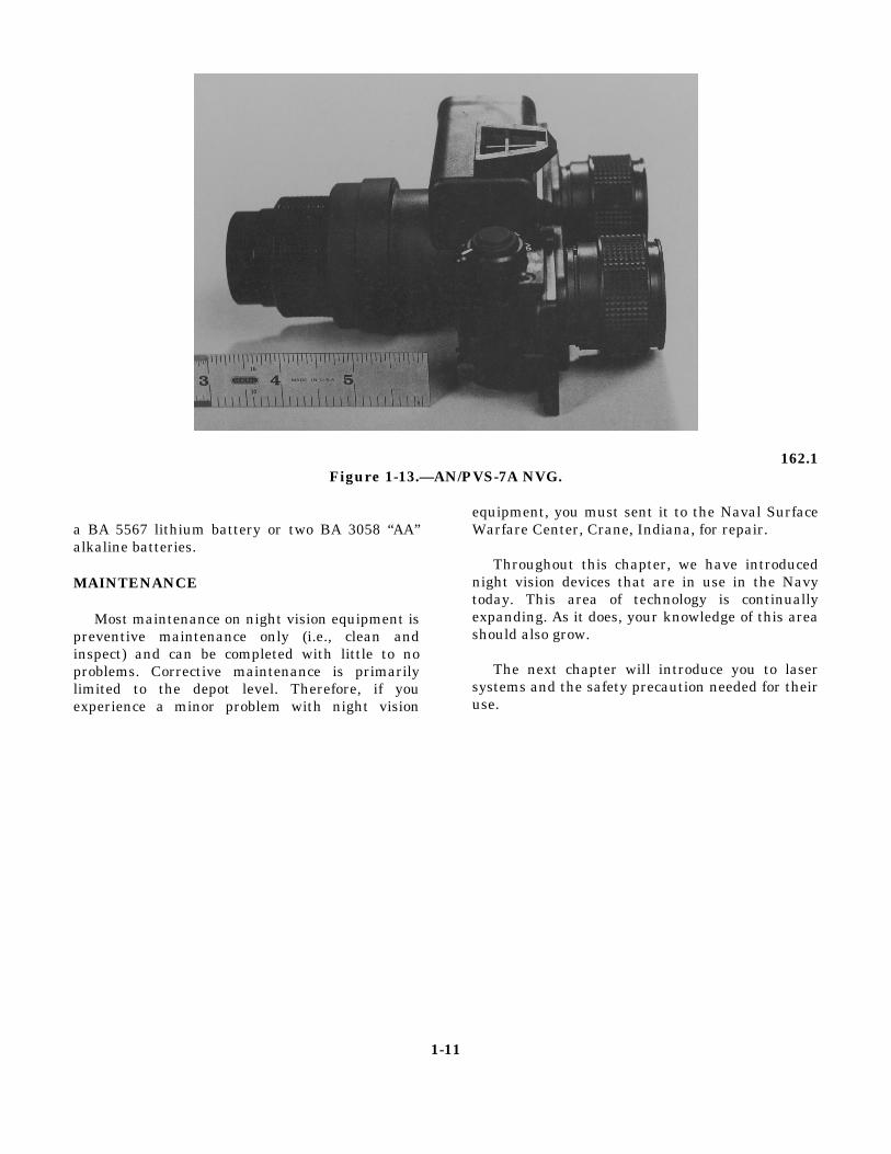
Figure 1-12 illustrates the Catseye NVG. Thissight is used in fixed wing military aircraft as apilot aid during nighttime operations. The imageintensifier assemblies are mounted above thepilot’s line of sight so they do not interfere withforward vision. In this sight, the intensified imageis superimposed on the “real world” image. Thisallows the pilot to see both the intensified image of
the scene outside the cockpit and the cockpitdisplays simultaneously.
The Catseye weighs only 1.7 pounds. It has a30-degree field of view and, like the AVS-6, islimited to a range of 200 feet. It is powered by two“AA” lithium batteries.
AN/PVS-7A NVG
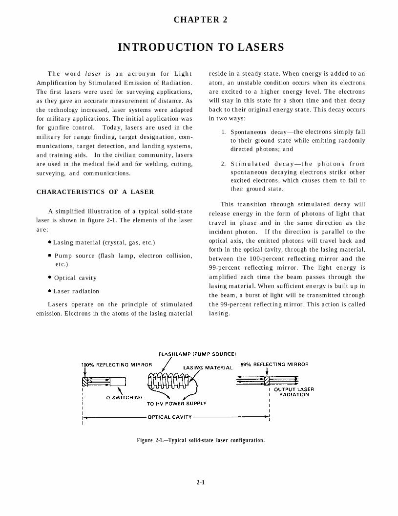
The AN/PVS-7A, shown in figure 1-13, is usedin the fleet for short-range observation and chartreading. It has a monocular design, which resultsin lower system weight.
The PVS-7A has a range of 200 to 350 yardsand a 40-degree field of view. It can be powered byeither
161.2Figure 1-12.—Catseye NVG.
1-10
162.1Figure 1-13.—AN/PVS-7A NVG.
a BA 5567 lithium battery or two BA 3058 “AA”alkaline batteries.
MAINTENANCE
Most maintenance on night vision equipment ispreventive maintenance only (i.e., clean andinspect) and can be completed with little to noproblems. Corrective maintenance is primarilylimited to the depot level. Therefore, if youexperience a minor problem with night vision
equipment, you must sent it to the Naval SurfaceWarfare Center, Crane, Indiana, for repair.
Throughout this chapter, we have introducednight vision devices that are in use in the Navytoday. This area of technology is continuallyexpanding. As it does, your knowledge of this areashould also grow.
The next chapter will introduce you to lasersystems and the safety precaution needed for theiruse.
1-11

CHAPTER 2
INTRODUCTION TO LASERS
The word laser is an acronym for LightAmplification by Stimulated Emission of Radiation.The first lasers were used for surveying applications,as they gave an accurate measurement of distance. Asthe technology increased, laser systems were adaptedfor military applications. The initial application wasfor gunfire control. Today, lasers are used in themilitary for range finding, target designation, com-munications, target detection, and landing systems,and training aids. In the civilian community, lasersare used in the medical field and for welding, cutting,surveying, and communications.
CHARACTERISTICS OF A LASER
A simplified illustration of a typical solid-statelaser is shown in figure 2-1. The elements of the laserare:
. Lasing material (crystal, gas, etc.)
. Pump source (flash lamp, electron collision,etc.)
l Optical cavity
. Laser radiation
Lasers operate on the principle of stimulatedemission. Electrons in the atoms of the lasing material
reside in a steady-state. When energy is added to anatom, an unstable condition occurs when its electronsare excited to a higher energy level. The electronswill stay in this state for a short time and then decayback to their original energy state. This decay occursin two ways:
1.
2.
Spontaneous decay—the electrons simply fallto their ground state while emitting randomlydirected photons; and
Stimulated decay—the photons fromspontaneous decaying electrons strike otherexcited electrons, which causes them to fall totheir ground state.
This transition through stimulated decay willrelease energy in the form of photons of light thattravel in phase and in the same direction as theincident photon. If the direction is parallel to theoptical axis, the emitted photons will travel back andforth in the optical cavity, through the lasing material,between the 100-percent reflecting mirror and the99-percent reflecting mirror. The light energy isamplified each time the beam passes through thelasing material. When sufficient energy is built up inthe beam, a burst of light will be transmitted throughthe 99-percent reflecting mirror. This action is calledlasing.
Figure 2-1.—Typical solid-state laser configuration.
2-1

Figure 2-2.-Divergence of a conventional light source.
Light from a conventional light source spreadsrapidly, as illustrated in figure 2-2. The intensity maybe large at the source, but it decreases rapidly as thedistance from the source increases. In contrast, theoutput of the laser, shown in figure 2-3, has a verysmall divergence and the beam intensity at reasonabledistances is almost the same as the intensity at thesource. Therefore, relatively low-power lasersproject more energy at a single wavelength within anarrow beam than do much more powerful con-ventional light sources.
CHARACTERISTICSMATERIALS
Material will either
OF REFLECTIVE
reflect, absorb, or transmitlight rays. Reflection of light is best illustrated by a
mirror. When light rays strike a mirror, almost all ofthe energy will be reflected. Figure 2-4 shows how aray of light is redirected as it strikes a plastic or glasssurface. The sum of the energy transmitted, absorbed,and reflected will equal the amount of energy thatstrikes the surface.
A surface is considered to be specular if the sizeof the surface imperfections and variations are muchsmaller than the wavelength of the striking opticalradiation. When the imperfections are randomlyoriented and are much larger than the wavelength, thesurface is considered to be diffuse.
Specular Reflection
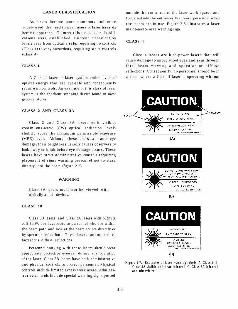
A flat specular surface will not change thedivergence of the striking beam of light significantly.
Figure 2-3.—Divergence of a laser source.
2-2
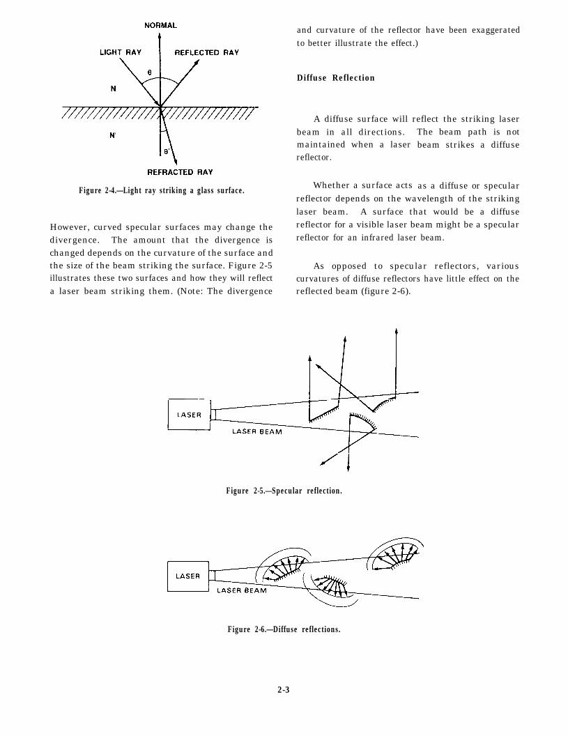
Figure 2-4.—Light ray striking a glass surface.
However, curved specular surfaces may change thedivergence. The amount that the divergence ischanged depends on the curvature of the surface andthe size of the beam striking the surface. Figure 2-5illustrates these two surfaces and how they will reflecta laser beam striking them. (Note: The divergence
and curvature of the reflector have been exaggeratedto better illustrate the effect.)
Diffuse Reflection
A diffuse surface will reflect the striking laserbeam in all directions.maintained when a laserreflector.
Whether a surface acts
The beam path is notbeam strikes a diffuse
as a diffuse or specularreflector depends on the wavelength of the strikinglaser beam. A surface that would be a diffusereflector for a visible laser beam might be a specularreflector for an infrared laser beam.
As opposed to specular reflectors, variouscurvatures of diffuse reflectors have little effect on thereflected beam (figure 2-6).
Figure 2-5.—Specular reflection.
Figure 2-6.—Diffuse reflections.
2-3
LASER CLASSIFICATION
As lasers became more numerous and morewidely used, the need to warn users of laser hazardsbecame apparent. To meet this need, laser classifi-cations were established. Current classificationlevels vary from optically safe, requiring no controls(Class 1) to very hazardous, requiring strict controls(Class 4).
CLASS 1
A Class 1 laser or laser system emits levels ofoptical energy that are eye-safe and consequentlyrequire no controls. An example of this class of lasersystem is the checkout scanning device found in mostgrocery stores.
CLASS 2 AND CLASS 3A
Class 2 and Class 3A lasers emit visible,continuous-wave (CW) optical radiation levelsslightly above the maximum permissible exposure(MPE) level. Although these lasers can cause eyedamage, their brightness usually causes observers tolook away or blink before eye damage occurs. Theselasers have strict administrative controls requiringplacement of signs warning personnel not to staredirectly into the beam (figure 2-7).
WARNING
Class 3A lasers must not beoptically-aided devices.
CLASS 3B
viewed with
Class 3B lasers, and Class 3A lasers with outputsof 2.5mW, are hazardous to personnel who are withinthe beam path and look at the beam source directly orby specular reflection. These lasers cannot producehazardous diffuse reflections.
Personnel working with these lasers should wearappropriate protective eyewear during any operationof the laser. Class 3B lasers have both administrativeand physical controls to protect personnel. Physicalcontrols include limited access work areas. Adminis-trative controls include special warning signs posted
outside the entrances to the laser work spaces andlights outside the entrances that warn personnel whenthe lasers are in use. Figure 2-8 illustrates a lasermaintenance area warning sign.
CLASS 4
Class 4 lasers are high-power lasers that willcause damage to unprotected eyes and skin throughintra-beam viewing and specular or diffusereflections. Consequently, no personnel should be ina room where a Class 4 laser is operating without
Figure 2-7.—Examples of laser warning labels: A. Class 2; B.Class 3A visible and near infrared; C. Class 3A infraredand ultraviolet.
2-4
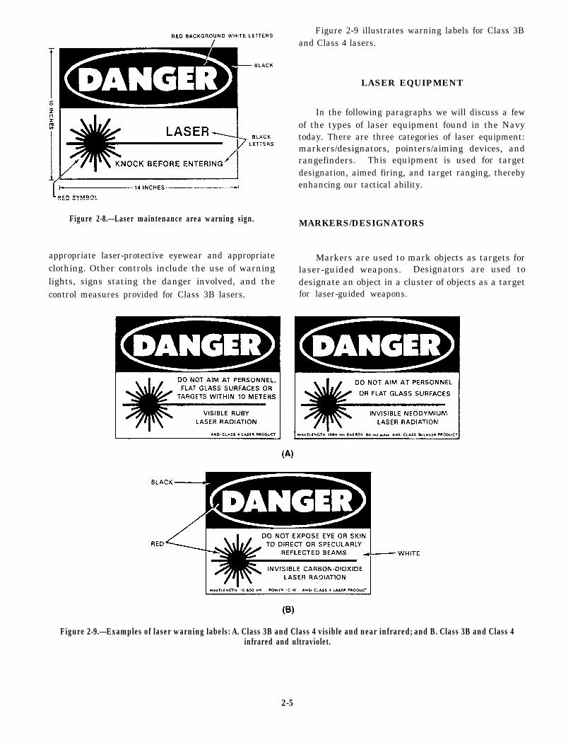
Figure 2-9 illustrates warning labels for Class 3Band Class 4 lasers.
Figure 2-8.—Laser maintenance area warning sign.
appropriate laser-protective eyewear and appropriateclothing. Other controls include the use of warninglights, signs stating the danger involved, and thecontrol measures provided for Class 3B lasers.
LASER EQUIPMENT
In the following paragraphs we will discuss a fewof the types of laser equipment found in the Navytoday. There are three categories of laser equipment:markers/designators, pointers/aiming devices, andrangefinders. This equipment is used for targetdesignation, aimed firing, and target ranging, therebyenhancing our tactical ability.
MARKERS/DESIGNATORS
Markers are used to mark objects as targets forlaser-guided weapons. Designators are used todesignate an object in a cluster of objects as a targetfor laser-guided weapons.
Figure 2-9.—Examples of laser warning labels: A. Class 3B and Class 4 visible and near infrared; and B. Class 3B and Class 4infrared and ultraviolet.
2-5

LTM86 Compact Laser Designator (CLD)
The LTM86 CLD, illustrated in figure 2-10, is aman-portable unit used to obtain a close estimateof range to a target or to designate a target forlaser guided munitions.
The CLD is a Class 4 laser with a 7-degree fieldof view and a range of 5 kilometers when used as adesignator, and 50 meters to 10 kilometers whenused as a rangefinder. It can be powered by eithera lead acid mission battery or a nickel-cadmiumtraining battery. Safety eyewear must have anoptical density (OD) with a rating of 4.5 at awavelength of 1064 nano-meters.
Special Operations Forces Laser Marker(SOFLAM)
The SOFLAM, illustrated in figure 2-11, is acompact, lightweight, man-portable unit that isused to obtain a close estimate of range to a targetor to designate a target for laser-guidedmunitions. This unit has provisions for tripod
mounting and remote operation and can directlyaccept a night vision sight for 24-hour observation.
The SOFLAM is a Class 4 laser that has a 5.6-degree field of view and a range of 5 kilometers asa designator and 200 meters to 10 kilometers as arangefinder. It weighs 9.1 pounds and is poweredby a either BA 5590 lithium battery, a BB 590rechargeable battery, or 28-volt vehicular power.The safety eyewear must have an OD of 4 at awavelength of 1064 nano-meters.
POINTERS/AIMING DEVICES
These devices are used for aimed firing ofhand-carried weapons. They will produce a splashof light at the point of impact for the weapon’sprojectile.
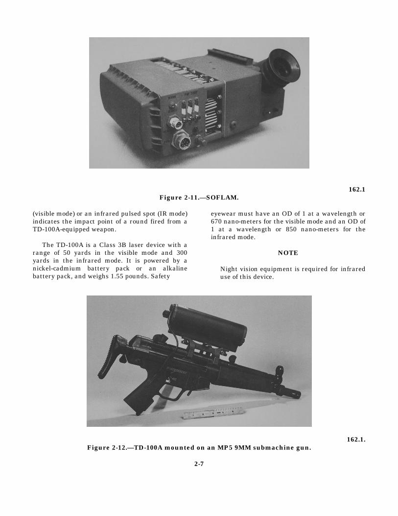
TD-100A Laser Target Designator (AimingDevice)
The TD-100A, illustrated in figure 2-12, is aself-contained battery-powered opticalsighting/laser aiming device designed formounting on the M12A1 rifle or the MP5 9MMsubmachine gun. A red spot
162.1Figure 2-10.—LTM86 CLD.
2-6
162.1Figure 2-11.—SOFLAM.
(visible mode) or an infrared pulsed spot (IR mode)indicates the impact point of a round fired from aTD-100A-equipped weapon.
The TD-100A is a Class 3B laser device with arange of 50 yards in the visible mode and 300yards in the infrared mode. It is powered by anickel-cadmium battery pack or an alkalinebattery pack, and weighs 1.55 pounds. Safety
eyewear must have an OD of 1 at a wavelength or670 nano-meters for the visible mode and an OD of1 at a wavelength or 850 nano-meters for theinfrared mode.
NOTE
Night vision equipment is required for infrareduse of this device.
162.1.Figure 2-12.—TD-100A mounted on an MP5 9MM submachine gun.
2-7
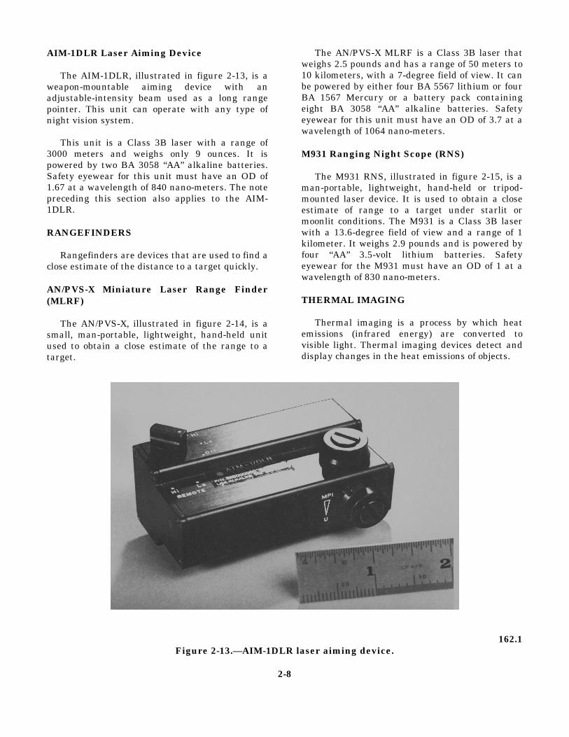
AIM-1DLR Laser Aiming Device
The AIM-1DLR, illustrated in figure 2-13, is aweapon-mountable aiming device with anadjustable-intensity beam used as a long rangepointer. This unit can operate with any type ofnight vision system.
This unit is a Class 3B laser with a range of3000 meters and weighs only 9 ounces. It ispowered by two BA 3058 “AA” alkaline batteries.Safety eyewear for this unit must have an OD of1.67 at a wavelength of 840 nano-meters. The notepreceding this section also applies to the AIM-1DLR.
RANGEFINDERS
Rangefinders are devices that are used to find aclose estimate of the distance to a target quickly.
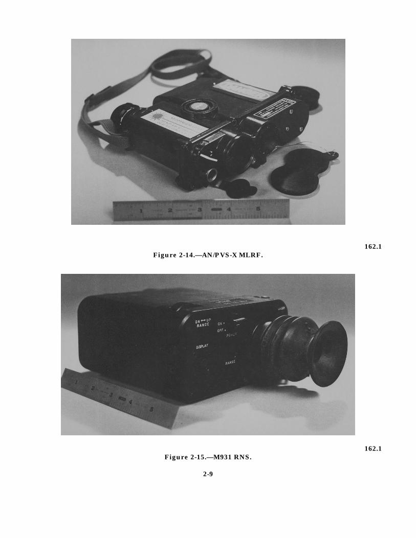
AN/PVS-X Miniature Laser Range Finder(MLRF)
The AN/PVS-X, illustrated in figure 2-14, is asmall, man-portable, lightweight, hand-held unitused to obtain a close estimate of the range to atarget.
The AN/PVS-X MLRF is a Class 3B laser thatweighs 2.5 pounds and has a range of 50 meters to10 kilometers, with a 7-degree field of view. It canbe powered by either four BA 5567 lithium or fourBA 1567 Mercury or a battery pack containingeight BA 3058 “AA” alkaline batteries. Safetyeyewear for this unit must have an OD of 3.7 at awavelength of 1064 nano-meters.
M931 Ranging Night Scope (RNS)
The M931 RNS, illustrated in figure 2-15, is aman-portable, lightweight, hand-held or tripod-mounted laser device. It is used to obtain a closeestimate of range to a target under starlit ormoonlit conditions. The M931 is a Class 3B laserwith a 13.6-degree field of view and a range of 1kilometer. It weighs 2.9 pounds and is powered byfour “AA” 3.5-volt lithium batteries. Safetyeyewear for the M931 must have an OD of 1 at awavelength of 830 nano-meters.
THERMAL IMAGING
Thermal imaging is a process by which heatemissions (infrared energy) are converted tovisible light. Thermal imaging devices detect anddisplay changes in the heat emissions of objects.
162.1Figure 2-13.—AIM-1DLR laser aiming device.
2-8
162.1Figure 2-14.—AN/PVS-X MLRF.
162.1Figure 2-15.—M931 RNS.
2-9
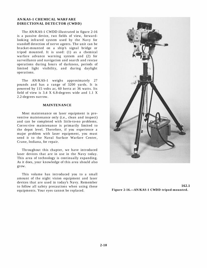
AN/KAS-1 CHEMICAL WARFAREDIRECTIONAL DETECTOR (CWDD)
The AN/KAS-1 CWDD illustrated in figure 2-16is a passive device, two fields of view, forward-looking infrared system used by the Navy forstandoff detection of nerve agents. The unit can bebracket-mounted on a ship’s signal bridge ortripod mounted. It is used: (1) as a chemicalwarfare advance warning system and (2) forsurveillance and navigation and search and rescueoperations during hours of darkness, periods oflimited light visibility, and during daylightoperations.
The AN/KAS-1 weighs approximately 27pounds and has a range of 3200 yards. It ispowered by 115 volts ac, 60 hertz at 36 watts. Itsfield of view is 3.4 X 6.8-degrees wide and 1.1 X2.2-degrees narrow.
MAINTENANCE
Most maintenance on laser equipment is pre-ventive maintenance only (i.e., clean and inspect)and can be completed with little-to-no problems.Correc-tive maintenance is primarily limited tothe depot level. Therefore, if you experience amajor problem with laser equipment, you mustsend it to the Naval Surface Warfare Center,Crane, Indiana, for repair.
Throughout this chapter, we have introducedlaser devices that are in use in the Navy today.This area of technology is continually expanding.As it does, your knowledge of this area should alsogrow.
This volume has introduced you to a smallamount of the night vision equipment and laserdevices that are used in today’s Navy. Rememberto follow all safety precautions when using theseequipments. Your eyes cannot be replaced.
162.1Figure 2-16.—AN/KAS-1 CWDD tripod-mounted.
2-10

APPENDIX I
REFERENCES USED TO DEVELOPTHE TRAMAN
General Information, Naval Surface Warfare Center, Code 805, Crane, Ind.,1993.
Technical Manual, LASER Safety, E0410-BA-GYD-010\7034 LASER, Spaceand Naval Warfare Systems Command, Washington, D.C., August 1988.
AI-1


INDEX
C
Categories of laser equipment, 2-5
markers/designators, 2-5
pointers/aiming devices, 2-6
rangefinders, 2-8
Characteristics of a laser, 2-1
spontaneous decay, 2-1
stimulated decay, 2-1
E
Electro-optical devices, 1-2
AN/AVS-6 NVG, 1-9
AN/PAS-6 metascope, 1-2
AN/PVS-4 weapons NVS, 1-6
AN/PVS-5C NVG, 1-9
AN/PVS-7A NVG, 1-10
AN/TVS-5 weapons NVS, 1-4
Aquila NVS, 1-6
catseye NVG, 1-10
KN200 NVS, 1-9
M921 Submersible NVS, 1-6
MK37 night vision sight (NVS), 1-4
nite-eye pockctscope, 1-2
L
Laser classification, 2-4
Laser safety, 2-2
diffuse reflection, 2-3
laser classification, 2-4
Laser safety—Continued
laser maintenance area warning signs, 2-5
laser warning labels, 2-4, 2-5
specular reflection, 2-2
Laser equipment, 2-5
AIM-1DLR, 2-8
AN/KAS-1 CWDD, 2-10
AN/PVS-X MLRF, 2-8
categories, 2-5
LTM86 CLD, 2-6
M931 RNS, 2-8
SOFLAM, 2-6
TD-100A, 2-6
Lasers, 2-1
categories of laser equipment, 2-5
characteristics of a laser, 2-1
chemical warfare, 2-10
thermal imaging, 2-8
N
Night vision equipment, 1-1
batteries, 1-2
crew-served sights, 1-4
hand-held night vision sights, 1-2
individual-served sights, 1-6
maintenance, 1-11
night vision goggle(NVG), 1-9
T
The human eye, 1-1
INDEX-1