Embed Size (px)
Citation preview
U.S. Department of Transportation Federal Aviation Administration
AdvisoryCircular
Subject: USE OF NONDESTRUCTIVE
TESTING IN THE EVALUATION OF AIRPORT PAVEMENTS
Date: 12-29-04 Initiated by: AAS-100
AC No.: 150/5370-11A Change:
1. PURPOSE OF THIS ADVISORY CIRCULAR. This advisory circular (AC) focuses on nondestructive testing (NDT) equipment that measures pavement surface deflections after applying a static or dynamic load to the pavement. It also briefly introduces other types of nondestructive measuring equipment to illustrate how supplementing NDT data with other test data may improve the quality and reliability of the pavement evaluation. 2. APPLICATION OF THIS AC. This AC provides guidance and recommendations on data-collection equipment and methods of data analysis that are used to conduct NDT; however, other methods, techniques, and variations of those outlined here may be used provided the appropriate local Federal Aviation Administration (FAA) Airports Office approves them. 3 CANCELLATION. AC 150/5370-11 Use of Nondestructive Testing Devices in the Evaluation of Airport Pavements, dated June 5, 1976, is cancelled.
4. USE OF METRICS. To promote an orderly transition to metric units, this AC contains both English and metric dimensions. 5. COPIES OF THIS AC. The FAA is in the process of making all ACs available to the public through the Internet. These ACs may be found by selecting the Regulations and Policies link on the FAA home page (www.faa.gov). You may also request a printed copy of this and other ACs from the United States (U.S.) Department of Transportation, Subsequent Business Office, Annmore East Business Center, 3341 Q 75th Avenue, Landover, MD, 20785.
David L. Bennett Director, Office of Airport Safety and Standards

AC 150/5370-11A 12/29/2004
Page i
CONTENTS
CHAPTER 1 – INTRODUCTION.............................................................................................................................1 1. GENERAL. .........................................................................................................................................1 2. BACKGROUND.................................................................................................................................1 3. LIMITATIONS TO NDT...................................................................................................................2 4. RELATED ADVISORY CIRCULARS. ...........................................................................................2 5. ORGANIZATION OF THIS AC. .....................................................................................................2
CHAPTER 2 – DESCRIPTION OF NDT PROCESS..............................................................................................3 6. GENERAL. .........................................................................................................................................3 7. PAVEMENT STIFFNESS AND SENSOR RESPONSE.................................................................3 8. DEFLECTION BASIN.......................................................................................................................3 9. USE OF NDT DATA. .........................................................................................................................4
CHAPTER 3 – NONDESTRUCTIVE TESTING EQUIPMENT...........................................................................5 10. CATEGORIES OF EQUIPMENT....................................................................................................5 11. GENERAL REQUIREMENTS FOR NDT EQUIPMENT.............................................................6 12. STATIC DEVICES.............................................................................................................................6 13. VIBRATORY DEVICES. ..................................................................................................................7 14. IMPULSE DEVICES. ........................................................................................................................7
CHAPTER 4 – REQUIREMENTS FOR NONDESTRUCTIVE TESTING EQUIPMENT................................9 15. NEED FOR STANDARIZATION. ...................................................................................................9 16. FAA SENSITIVITY STUDY.............................................................................................................9 17. SUMMARY OF FAA POLICY.......................................................................................................10
CHAPTER 5 – TEST PLANNING ..........................................................................................................................11 18. JUSTIFICATION FOR NDT. .........................................................................................................11 19. NDT TEST OBJECTIVES. .............................................................................................................11 20. NDT TEST TYPES...........................................................................................................................12 21. TEST LOCATIONS AND SPACING.............................................................................................12 22. NDT TEST SKETCHES. .................................................................................................................12 23. SPECIAL CONSIDERATIONS......................................................................................................13
CHAPTER 6 – TEST PROCEDURES ....................................................................................................................14 24. EQUIPMENT MOBILIZATION....................................................................................................14 25. STARTUP OPERATIONS. .............................................................................................................14 26. DATA COLLECTION.....................................................................................................................15 27. SPECIAL TEST CONDITIONS. ....................................................................................................16 28. ONSITE REVIEW OF DATA.........................................................................................................17
CHAPTER 7 – DEFLECTION DATA ANALYSES..............................................................................................18 29. OVERVIEW OF PROCESS............................................................................................................18 30. PROCESS RAW DEFLECTION DATA. ......................................................................................18 31. BACK-CALCULATION ANALYSIS. ...........................................................................................20 32. PCC JOINT ANALYSIS..................................................................................................................28 33. PCC VOID ANALYSIS. ..................................................................................................................29 34. PCC DURABILITY ANALYSIS. ...................................................................................................30 35. SUMMARY.......................................................................................................................................31
CHAPTER 8 – NDT-BASED EVALUATION AND DESIGN INPUTS ..............................................................32 36. STATISTICALLY DERIVED INPUTS.........................................................................................32 37. USING NDT RESULTS IN FAA ANALYSIS PROGRAMS. ......................................................33 38. PCC LOSS OF SUPPORT...............................................................................................................36 39. SUMMARY.......................................................................................................................................36
APPENDIX 1 - FIGURES....................................................................................................................................... 1-1 APPENDIX 2 - TABLES ........................................................................................................................................ 2-1 APPENDIX 3 - GLOSSARY………………………………………………………………………………………3-1

AC 150/5370-11A 12/29/2004
Page ii
FIGURES
Appendix 1 Figure 1. Illustration of an Impulse Load Created by FWD.............................................................................. 1-1 Figure 2. Sensors Spaced Radially From the Load Plate ................................................................................... 1-1 Figure 3. Schematic of Deflection Basin............................................................................................................... 1-2 Figure 4. Comparison of Deflection Basin of Three Pavements ........................................................................ 1-2 Figure 5. Illustration of Static and Dynamic Force Components for Vibratory NDT..................................... 1-3 Figure 6. Illustration of Time to Peak Load for Impulse-Based NDT Equipment........................................... 1-3 Figure 7. Benkleman Beam ................................................................................................................................... 1-4 Figure 8. Dynaflect Deflection Trailer ................................................................................................................. 1-4 Figure 9. Road Rater ............................................................................................................................................. 1-5 Figure 10. KUAB FWD ........................................................................................................................................... 1-5 Figure 11. Dynatest FWD........................................................................................................................................ 1-6 Figure 12. PHOENIX FWD (Redesigned by Viatest) ........................................................................................... 1-6 Figure 13. JILS HWD.............................................................................................................................................. 1-7 Figure 14. Evaluation of HWD Force Linearity in Terms of ISM....................................................................... 1-7 Figure 15. Evaluation of HWD Force Linearity in Terms of Subgrade Elastic Modulus ................................. 1-8 Figure 16. NDT Test Locations within a PCC Slab .............................................................................................. 1-8 Figure 17. Illustration of Load Transfer Across a PCC Joint.............................................................................. 1-9 Figure 18. Example Runway or Taxiway Sketch when Centerline Lies on Slab Joint...................................... 1-9 Figure 19. Example Runway or Taxiway Sketch when Centerline Does Not Lie on Slab Joint ..................... 1-10 Figure 20. Example Runway or Taxiway Sketch for HMA Pavements ............................................................ 1-10 Figure 21. Thermal Curling in PCC Slab From Temperature Changes........................................................... 1-11 Figure 22. Location of Additional Sensors for Corner and Joint Testing......................................................... 1-11 Figure 23. NDT Data Analysis and Design Flowchart........................................................................................ 1-12 Figure 24. ISM Plot Used to Identify Pavement Section Breaks........................................................................ 1-12 Figure 25. Normalized Deflection Plot Used to Identify Pavement Section Breaks ......................................... 1-13 Figure 26. Normalized Subgrade Deflection Plot Used to Identify Pavement Sections ................................... 1-13 Figure 27. Process for Data Preparation and Back-Calculation Method Selection ......................................... 1-14 Figure 28. Flowchart for Closed-Form Back-Calculation Using AREA Method............................................. 1-14 Figure 29. Illustration of Basin AREA for SHRP Four-Sensor Configuration................................................ 1-15 Figure 30. Comparison of Measured and Calculated Deflection Basins........................................................... 1-15 Figure 31. Back-Calculation Procedures for an Elastic-Layer Based Analysis................................................ 1-16 Figure 32. Initial BAKFAA Run for Example 2.................................................................................................. 1-17 Figure 33. Second BAKFAA Run for Example 2................................................................................................ 1-17 Figure 34. Output from Second BAKFAA Run for Example 2 ......................................................................... 1-18 Figure 35. Deflection vs. Stress LTE Relationship for 12-inch (300 mm) Diameter Load Plate..................... 1-18 Figure 36. Example Plot of Transverse Joint ∆LTE for a 10,000-foot (3,050 m) Taxiway ................................ 1-19 Figure 37. Void Detection Beneath PCC Slabs.................................................................................................... 1-19 Figure 38. Example Plot of Transverse Joint Voids for a 10,000-foot (3,050 m) Taxiway .............................. 1-20 Figure 39. Example Plot of ratioISM for Transverse Joint for HMA Overlaid PCC......................................... 1-20 Figure 40. Histogram of ISM Values for Section 3 in Figure 24........................................................................ 1-21

AC 150/5370-11A 12/29/2004
Page iii
TABLES
Appendix 2 Table 1. Summary of Nondestructive Testing Measuring Equipment ............................................................ 2-1 Table 2. Detailed Specifications for Selected FWDs and HWDs …...………………………………………...2-2 Table 3. ASTM Standards for Deflection Measuring Equipment.................................................................... 2-2 Table 4. Common Sensor Configurations .......................................................................................................... 2-3 Table 5. Typical Runway and Taxiway Test Locations and Spacing, feet (m) ............................................... 2-3 Table 6. Typical Apron Test Locations and Frequency.................................................................................... 2-3 Table 7. FAA Software Tools for Pavement Analysis, Evaluation, and Design.............................................. 2-4 Table 8. Theoretical Basis of FAA Software Tools............................................................................................ 2-4 Table 9. Required Sensor Distance (inch) from Load Plate with 12-inch (300 mm) Diameter ..................... 2-4 Table 10. Type of Back-Calculation Software Tool that is Required for Each Load Scenario ....................... 2-5 Table 11. AREA-based Constants for Equation 8 ............................................................................................... 2-5 Table 12. Constants for
*rd (Equation 11) ............................................................................................................. 2-5
Table 13. Typical Modulus Values and Ranges for Paving Materials ............................................................... 2-6 Table 14. Typical Poisson's Ratios for Paving Materials .................................................................................... 2-6 Table 15. Linear Analysis Back-Calculation Programs...................................................................................... 2-7 Table 16. Nonlinear Analysis Back-Calculation Programs ................................................................................ 2-8 Table 17. Seed Modulus and Poisson's Ratios for Example Problem 2............................................................. 2-8 Table 18. Pavement Joint Performance Ratings.................................................................................................. 2-9 Table 19. Statistical Summary of ISM Values for Each Section in Figure 24................................................... 2-9 Table 20. Required FAA Advisory Circular Evaluation and Design Inputs................................................... 2-10 Table 21. Allowable Modulus Values for LEDFAA (AC 150/5320-6), psi (MPa)........................................... 2-11 Table 22. HMA Pavement Base and Subbase Modulus and Equivalency Factor Inputs............................... 2-11 Table 23. Recommended Reduced k-Values for Loss of Support Conditions................................................. 2-11

AC 150/5370-11A 12/29/2004
Page 1
CHAPTER 1–INTRODUCTION
1. GENERAL. Nondestructive testing (NDT) can make use of many types of data-collection equipment and methods of data analysis. In most cases, the data can be used to evaluate the structural or functional condition of a pavement. This AC focuses on collecting and analyzing NDT data, which are used to accomplish the following:
a. Evaluate the load-carrying capacity of existing pavements.
b. Provide material properties of in-situ pavement and subgrade layers for the design of pavement rehabilitation alternatives that include extensive maintenance and repair work (restoration), functional and structural overlays, partial reconstruction (e.g., runway keel), and complete reconstruction.
c. Compare parts of a pavement system to each other to gain relative strength and/or condition within that section. The results of the NDT can show which segments are the strongest and which are the weakest. These results can then be used to focus follow-on testing.
d. Provide structural performance data to supplement pavement condition index (PCI) survey data in an Airport Pavement Management System (APMS).
To accomplish these objectives, this AC provides an overview of the various types of NDT equipment; identifies those scenarios where NDT provides the most benefit to the engineer and owner; describes how NDT test plans should be developed for data collection; presents several methods for using the NDT data to characterize a pavement; and describes how the results from NDT should be used as inputs to evaluation, design, and pavement management analyses that comply with FAA policy. There are many software programs that can be used to collect and analyze NDT data, and this AC will reference many of them. The FAA's back-calculation program, BAKFAA, can be downloaded from the FAA website and can be used to analyze NDT data, subject to the limitations discussed herein. 2. BACKGROUND. Recent advances in hardware and software technology have significantly improved NDT equipment, data collection, and analysis software. Not only has NDT work been conducted on hundreds of airport pavements throughout the
world, it has been extensively used to evaluate and design interstate highways, state highways, tollways, county roads, city streets, and seaports. NDT is also being used by researchers to improve pavement evaluation and design methodologies. The Federal Highway Administration (FHWA) uses NDT equipment to collect data at hundreds of test section sites throughout the U.S. The FAA currently uses NDT equipment to collect data at the National Airport Pavement Test Facility (NAPTF) in Atlantic City, NJ to advance airport pavement evaluation and design methods. There are several advantages to using NDT, in lieu of, or supplement traditional destructive tests. Most important, is the capability to quickly gather data at several locations while keeping a runway, taxiway, or apron operational during these 2-minute to 3-minute tests, provided the testing is under close contact with Air Traffic Control. Without NDT, structural data must be obtained from numerous cores, borings, and excavation pits on an existing airport pavement. This can be very disruptive to airport operations. For example, to conduct a plate load test for measuring in-situ modulus of subgrade reaction, k, tests, 4-foot (1.2 m) by 6-foot (1.8 m) pits are prepared by removing each pavement layer until the subgrade is exposed. Once the plate-bearing test is completed, the repair of a test pit can be expensive and may keep the test area closed for several days. Nondestructive tests are economical to perform and data can be collected at up to 250 locations per day. The NDT equipment measures pavement surface response (i.e., deflections) from an applied dynamic load that simulates a moving wheel. The magnitude of the applied dynamic load can be varied so that it is similar to the load on a single wheel of the critical or design aircraft. Pavement deflections are recorded directly beneath the load plate and at typical radial offsets of 12 inches (300 mm), out to typical distances of 60 inches (1,500 mm) to 72 inches (1,800 mm). The deflection data that are collected with NDT equipment can provide both qualitative and quantitative data about the strength of a pavement at the time of testing. The raw deflection data directly beneath the load plate sensor provides an indication of the strength of the entire pavement structure. Likewise, the raw deflection data from the outermost sensor provides an indication of subgrade strength.

AC 150/5370-11A 12/29/2004
Page 2
In addition, when deflection or stiffness profile plots are constructed with deflection data from all test locations on a pavement facility, relatively strong and weak areas become readily apparent. Quantitative data from NDT include material properties of each pavement and subgrade layer that engineers use with other physical properties, such as layer thicknesses and interface bonding conditions, to evaluate the structural performance of a pavement or investigate strengthening options. Most of the material property information is obtained using software programs that process and analyze raw NDT data. Once material properties, such as modulus of elasticity, E, and modulus of subgrade reaction, k, are computed, the engineer can conduct structural evaluations of existing pavements, design structural improvements, and develop reconstruction pavement cross-sections using subgrade strength data. 3. LIMITATIONS TO NDT. Although NDT has many advantages, it also has some limitations. NDT is a very good methodology for assessing the structural condition of an airfield pavement; however, engineers must use other methods to evaluate the functional condition of the pavement, e.g., visual condition, smoothness, and friction characteristics. The visual condition is most frequently assessed using the PCI in accordance with American Society for Testing and Materials (ASTM) D 5340, Standard Test Method for Airport Pavement Condition Index Surveys, and AC 150/5380-6, Guidelines and Procedures for Maintenance of Airport Pavements. Once the NDT-based structural and functional conditions are known, the engineer can assign an overall pavement condition rating. The differentiation between structural and functional performance is important in developing requirements for pavement rehabilitation. For example, a pavement can have a low PCI due to environmental distress, yet the pavement has sufficient thickness to accommodate structural loading. The converse may also be true, whereby a pavement may be in good condition, but has a low structural life due to proposed heavier aircraft loading. In addition, while NDT may provide excellent information about structural capacity, the engineer may still require other important engineering properties of the pavement layers, such as grain-size distribution of the subgrade to determine swelling and heaving potential. For subsurface drainage evaluation and design, grain-size distribution and permeability tests may help assess the hydraulic capacity of the base, subbase, and subgrade.
It should also be noted that quantitative results obtained from raw NDT data are model dependent. The results depend on the structural models and software algorithms that are used by programs that process NDT data and perform a back-calculation of layer material properties. Because of the model dependencies of NDT software analysis tools, the engineer should exercise caution when evaluating selected pavement types, such as continuously reinforced concrete pavement, post-tensioned concrete, and pre-tensioned concrete. The structural theory and performance models for these pavement types are significantly different than traditional pavements, which include Asphalt Cement (HMA), jointed plain Portland Cement Concrete (PCC), jointed reinforced PCC, HMA overlaid PCC, and PCC overlaid PCC. Finally, NDT conducted at different times during the year may give different results due to climatic changes. For example, tests conducted during spring thaw or after extended dry periods may provide non-representative results or inaccurate conclusions on pavement at subgrade strength. 4. RELATED ADVISORY CIRCULARS. The following ACs provides additional information regarding NDT and structural analysis of airport pavements:
a. 150/5320-6, Airport Pavement Design and Evaluation.
b. 150/5320-12, Measurement, Construction, and Maintenance of Skid Resistant Airport Pavement Surfaces.
c. 150/5335-5, Standardized Method of Reporting Airport Pavement Strength PCN.
d. 150/5380-6, Guidelines and Procedures for Maintenance of Airport Pavements.
5. ORGANIZATION OF THIS AC. The following chapters in this AC present an overview of the NDT data collection process and equipment that are used to collect the field data. The AC then focuses on how to prepare a test plan and develop procedures that should be used for data acquisition. The final chapters focus on processing the raw data to obtain pavement material characteristics that can then be used to evaluate a pavement's load-carrying capacity, remaining structural life, or strengthening requirements.

AC 150/5370-11A 12/29/2004
Page 3
CHAPTER 2–DESCRIPTION OF NDT PROCESS
6. GENERAL. NDT, using static or dynamic testing equipment, has proven useful in providing data on the structural properties of pavement and subgrade layers. The data are typically used to detect patterns of variability in pavement support conditions or to estimate the strength of pavement and subgrade layers. With this information, the engineer can design rehabilitation overlays and new/reconstructed cross-sections, or optimize a rehabilitation option that is developed from an APMS. This AC focuses on nondestructive testing equipment that measures pavement surface deflections after applying a static or dynamic load to the pavement. NDT equipment that imparts dynamic loads creates surface deflections by applying a vibratory or impulse load to the pavement surface through a loading plate. For vibratory equipment, the dynamic load is typically generated hydraulically, as is the case for the Road Rater, or by counter rotating masses, as is the case for the Dynaflect. For impulse devices, such as the Falling Weight Deflectometer (FWD), the dynamic load is generated by a mass free falling onto a set of rubber springs, as shown in Figure 1 in Appendix 1. The magnitude of the impulse load can be varied by changing the mass and/or drop height so that it is similar to that of a wheel load on the main gear of an aircraft. For both impulse and vibratory equipment, pavement response is typically measured by a series of sensors radially displaced from the loading plate, as shown in Figure 2. For static devices, such as the Benkleman Beam, a rebound deflection from a truck or other vehicle load is measured. Typically, the rebound deflection is measured only at the location of the load and not at the other radially spaced sensors shown in Figure 2. 7. PAVEMENT STIFFNESS AND SENSOR RESPONSE. The load-response data that NDT equipment measure in the field provides valuable information on the strength of the pavement structure. Initial review of the deflection under the load plate and at the outermost sensor, sensors D1 and D7 in Figure 2, respectively, is an indicator of pavement and subgrade stiffness. Although this information will not provide information about the strength of each pavement layer, it does provide a quick assessment of the pavement's overall strength and relative variability of strength within a particular facility (runway, taxiway, or apron).
Pavement stiffness is defined as the dynamic force divided by the pavement deflection at the center of the load plate. For both impulse and vibratory devices, the stiffness is defined as the load divided by the maximum deflection under the load plate. The Impulse Stiffness Modulus (ISM) and the Dynamic Stiffness Modulus (DSM) are defined as follows for impulse and vibratory NDT devices, respectively:
I(D)SM = L / do Where: I(D)SM = Impulse and Dynamic Stiffness Modulus (kips/inch) L = Applied Load (kips) do = Maximum Deflection of Load Plate (inches) 8. DEFLECTION BASIN. After the load is applied to the pavement surface, as shown in Figure 1, the sensors shown in Figure 2 are used to measure the deflections that produce what is commonly referred to as a deflection basin. Figure 3 shows the zone of load influence that is created by a FWD and the relative location of the sensors that measure the deflection basin area. The deflection basin area can then be used to obtain additional information about the individual layers in the pavement structure that cannot be obtained by using deflection data from a single sensor. The shape of the basin is determined by the response of the pavement to the applied load. The pavement deflection is the largest directly beneath the load and then decreases as the distance from the load increases. Generally, a weaker pavement will deflect more than a stronger pavement under the same load. However, the shape of the basin is related to the strengths of all the individual layers. To illustrate the importance of measuring the deflection basin, Figure 4 shows a comparison of three pavements. Pavement 1 is PCC and pavements 2 and 3 are HMA. As expected, the PCC distributes the applied load over a larger area and has a smaller maximum deflection than the other two pavements. Although pavements 2 and 3 have the same cross- section and the same maximum deflection under the load plate, they would presumably perform differently under the same loading conditions because of the differences in base and subgrade strengths.

AC 150/5370-11A 12/29/2004
Page 4
In addition to each layer's material properties, other factors can contribute to differences in the deflection basins. Underlying stiff or apparent stiff layers, the temperature of the HMA layer during testing, moisture contents in each of the layers, and PCC slab warping and curling can affect deflection basin shapes. An important component in the evaluation process, then, is analysis of the NDT data to estimate the expected structural performance of each pavement layer and subgrade. 9. USE OF NDT DATA. There are many ways to use the NDT data to obtain those pavement characteristics that are needed to identify the causes of pavement distresses, conduct a pavement evaluation, or perform a strengthening design. Engineers can evaluate the NDT data using qualitative and quantitative procedures. Subsequent chapters present several methods that can be used to compute and evaluate such pavement characteristics as:
a. ISM, DSM, and normalized deflections.
b. Back-calculated elastic modulus of pavement layers and subgrade.
c. Correlations to conventional characterizations (e.g., California Bearing Ratio [CBR], k).
d. Crack and joint load transfer efficiency.
e. Void detection at PCC corners and joints.
These NDT-derived pavement characteristics can then be used in the FAA's evaluation and design procedures.

AC 150/5370-11A 12/29/2004
Page 5
CHAPTER 3–NONDESTRUCTIVE TESTING EQUIPMENT
This chapter introduces the various types of NDT equipment that are used to evaluate pavements. Although the AC focuses on NDT equipment, other types of nondeflection measuring equipment are introduced to illustrate how NDT data can be supplemented with other test data to improve the quality and reliability of the pavement evaluation. 10. CATEGORIES OF EQUIPMENT. Nondestructive testing equipment includes both deflection and nondeflection testing equipment. Deflection measuring equipment for nondestructive testing of airport pavements can be broadly classified as static or dynamic loading devices. Dynamic loading equipment can be further classified according to the type of forcing function used, i.e., vibratory or impulse devices. Nondeflection measuring equipment that can supplement deflection testing includes ground-penetrating radar, infrared thermography, dynamic cone penetrometer, and devices that measure surface friction, roughness, and surface waves.
a. Deflection Measuring Equipment. There are several categories of deflection measuring equipment: static, steady state (e.g., vibratory), and impulse load devices. A static device measures deflection at one point under a nonmoving load. Static tests are slow and labor intensive compared to the other devices. Examples of a static device include the Benkleman Beam and other types of plate bearing tests. Vibratory devices induce a steady-state vibration to the pavement with a dynamic force generator, as illustrated in Figure 5. As this figure shows, there is a small static load that seats the load plate on the pavement. The dynamic force is then generated at a precomputed frequency that causes the pavement to respond (deflect). The pavement deflections are typically measured with velocity transducers. There are several types of steady-state vibratory devices, including Dynaflect and Road Rater. Impulse load devices, such as the FWD or Heavy-Falling Weight Deflectometer (HWD), impart an impulse load to the pavement with free-falling weight that impacts a set of rubber springs, as illustrated in Figure 6. The time from A to B in this figure is the time required to lift the FWD weight package to the required drop height. The magnitude of the dynamic load depends on the mass of the weight and the height from which the weight is dropped.
The resultant deflections are typically measured with velocity transducers, accelerometers, or linear variable differential transducers (LVDT). Table 1 in Appendix 2 provides a summary of the various types of static, vibratory, and impulse load NDT equipment that are in use or in production today. The most popular and widely used NDT equipment falls in the impulse-based category. This category of NDT equipment is used extensively for airport, road, and seaport pavement testing.
b. Nondeflection Measuring Equipment. Several other types of nondestructive testing equipment are available that may assist the engineer in conducting a pavement evaluation, performing a pavement design, or implementing a pavement management system. The data that are collected from nondeflection measuring equipment often supplement NDT data or provide standalone information in pavement analysis work. While deflection data from NDT equipment are used primarily to evaluate the structural capacity and condition of a pavement, the following nondeflection measuring equipment can also be used:
(1) Ground-Penetrating Radar (GPR)⎯The most common uses of GPR data include measuring pavement layer thicknesses, identifying large voids, detecting the presence of excess water in structure, locating underground utilities, and investigating significant delamination between pavement layers.
(2) Spectral Analysis of Surface Waves (SASW)⎯SASW equipment provides data that can supplement NDT data. Unlike NDT equipment, which imparts much higher loads to the pavement, SASW equipment consists of small portable units that evaluate pavements from Rayleigh wave measurements that involve low strain levels. Engineers can then evaluate these data to compute the approximate thickness of pavement layers, layer modulus of elasticity values for comparison to NDT computed elasticity values, and approximate depth to rigid layers.
(3) Infrared Thermography (IR)⎯One of the most common uses of IR data is to determine if delamination has occurred between asphalt pavement layers.

AC 150/5370-11A 12/29/2004
Page 6
(4) Friction Characteristics⎯There are types of equipment that are available to conduct surface friction tests on a pavement. The methods of testing and several common types of friction testers for airports are addressed in AC 150/5320-12.
(5) Smoothness Characteristics⎯There are also several types of equipment that are available to collect surface profile data and to determine how aircraft may respond during taxi, takeoff, and landing.
(6) Dynamic Cone Penetrometer (DCP)⎯A DCP is another piece of equipment that can be used to supplement NDT data. If cores are taken through the pavement to verify the thickness of an HMA or PCC layer, the DCP can help evaluate the stiffness of the base, subbase, and subgrade. Data are recorded in terms of the number of blows per inch that is required to drive the cone-shaped end of the rod through each of the layers. Plots of these data provide information about the changes in layer types and layer strengths. 11. GENERAL REQUIREMENTS FOR NDT EQUIPMENT. If deflection measuring equipment is being considered for use in a pavement study, the engineer should first evaluate project requirements. To provide meaningful results, several general requirements should be considered regarding equipment capabilities. The quality of the NDT results will depend on several factors, such as the quality of the test plan, test procedures, and data analyses procedures, as described in subsequent chapters of this AC. In general, the value of NDT will be greater for primary airports compared to general aviation (GA) airports. However, if a GA airport supports, or will support, aircraft with a maximum gross takeoff weight greater than 30,000 pounds (13,500 kg), or heavy aircraft are expected to use the airport on an infrequent basis, NDT may be useful in evaluating the pavement. Also, because of the increasing number of business jets that operate from reliever and GA airports, NDT may add significant value to a GA pavement study. If nondestructive testing is indicated, the airport sponsor should consider the operational impacts of operating the equipment on the airside. While NDT equipment can collect data at many locations over a relatively short period of time, the airport may not be able to close a particular facility during peak periods of aircraft operations.
Depending on the frequency and types of NDT tests, the work on a typical runway that is 9,000 feet (2,750 m) long and 150 feet (45 m) wide normally takes 1 to 2 days. If peak traffic occurs during daylight hours, it may be more efficient to conduct the NDT at night when the facility can be closed for 6 to 8 hour periods. If the sponsor and engineer decide to conduct NDT, they should carefully consider the type of equipment that will be used for the study. In general, the equipment should be capable of imparting a dynamic load to the pavement that creates deflections and loads that are large enough to be accurately recorded with the sensors on the pavement surface. The required magnitude of the dynamic load will depend primarily on the thickness and strength of the pavement layers. If the deflections are adequate for the structure and type of aircraft that will use the pavement, the NDT equipment sensors should provide accurate and repeatable deflection measurements at each sensor location. Repeatability is important for two reasons. First, NDT may be conducted at multiple load levels to learn more about the pavement structure, such as whether voids exist or if the subgrade soil is stress sensitive and appears to get harder or softer with increasing load. To characterize the pavement properly, the sensors must accurately and consistently record deflection data. Second, because pavements deteriorate over time, subsequent pavement evaluation and NDT work may be important. To quantify the rate of deterioration, it is important to have reliable deflection data at different times during the pavement's design life. 12. STATIC DEVICES. The most common static device is the Benkleman Beam, although several other devices have been built to automate its use. Examples of automated beams include the Swedish La Croix Deflectograph; the British Transport and Road Research Laboratory Pavement Deflection Data Logging (PDDL), which is a modified La Croix Deflectograph; and Caltran's California Traveling Deflectometer. Figure 7 shows a Benkleman Beam that has not been automated. The Benkleman Beam measures the deflection under a static load, such as a truck or aircraft. The truck weight is normally 18,000 pounds (8,165 kg) or a single axle with dual tires. The tip of the beam is placed between the dual tires and the rebound deflection is measured as the vehicle moves away from the beam.

AC 150/5370-11A 12/29/2004
Page 7
The primary advantages that are associated with the Benkleman Beam are its simplicity and the numerous design procedures that have historically used beam data. Disadvantages to its use include longer testing time and the lack of repeatability of results as compared with more modern devices. The Benkleman Beam also does not typically provide deflection basin data for back-calculation of pavement layer moduli. 13. VIBRATORY DEVICES. Vibratory devices include the Dynaflect and the Road Rater.
a. Dynaflect. The Dynaflect, shown in Figure 8, is an electromechanical device for measuring dynamic deflection. It is mounted on a two-wheel trailer and is stationary when the measurements are taken. A 1,000-pound (5 kN) peak-to-peak sinusoidal load is applied through two rubber coated steel wheels at a fixed 8Hz frequency. The counter-rotating masses produce a sinusoidal pavement deflection, which is recorded by velocity transducers. Advantages of the Dynaflect include high reliability, low maintenance, and the ability to measure the deflection basin. A major disadvantage of the equipment is the low dynamic load amplitude, which is significantly less than normal aircraft loads. The relatively light load may not produce adequate deflections on heavy airport pavements and the back- calculated subgrade moduli may not be accurate. Therefore, the use of this device is only recommended for light load pavements serving aircraft less than 12,500 pounds (5,670 kg).
b. Road Rater. The Road Rater, shown in Figure 9, also measures dynamic deflection using a sinusoidal force generated by a hydraulic acceleration of a steel mass. Several models are available that have peak-to-peak loading that ranges from a low of 500 pounds (2 kN) to a high of 8,000 pounds (35 kN). Pavement response is measured at the center of the loading plate and at radial offset distances using four to seven velocity transducers, depending on the model. The Road Rater can measure deflection basins, as well as dynamic response over a broad range of frequencies. It has a rapid data acquisition system and its wide use has resulted in the availability of large amounts of data on pavement response and performance. The major disadvantage of the Road Rater is low force amplitude on some models.
14. IMPULSE DEVICES. These devices measure deflection using a free-falling mass onto rubber springs to produce an impulse load. The magnitude of the calculated dynamic load and the resultant pavement deflections are recorded. Generally, these devices fall into one of two categories: FWD and HWD. Most impulse devices are classified as a HWD when they are able to generate a maximum dynamic load that is greater than 34,000 pounds (150 kN). There are several manufacturers of FWDs and HWDs, including KUAB America, Dynatest Group, Phoenix Scientific, Inc., Foundation Mechanics, Inc., and Viatest. These impulse devices all share several common advantages for this type of deflection measuring equipment. The FWD and HWD are believed to better simulate moving wheel loads, can measure the extent of the deflection basin, have relatively fast data acquisition, and require only a small preload on the pavement surface. The disadvantages of the equipment are minimal and related more to the overall systems and different pulse durations used on different models. Table 2 provides a detailed summary of the impulse equipment specifications.
a. KUAB America. KUAB manufactures a FWD (Figure 10) and HWD, which include five models with load ranges up to 66,000 pounds (294 kN). The load is applied through a two-mass system, and the resultant dynamic response is measured with seismometers and LVDTs through a mass-spring reference system. The load plate is segmented to provide a uniform pressure distribution to the pavement.
b. Dynatest Group. Dynatest manufactures
both a FWD (Figure 11) and a HWD with models that generate dynamic loads up to 54,000 pounds (240 kN). The weights are dropped onto a rubber buffer system. Seven to nine velocity transducers are then used to measure the load and dynamic response.
c. Carl Bro Group. Carl Bro manufactures the
FWD and the HWD generating dynamic loads up to 56,000 pounds (250 kN). Furthermore, Carl Bro manufactures the portable FWD (LWD) – PRIMA 100 – for on-site measurement and analysis of collected data.

AC 150/5370-11A 12/29/2004
Page 8
All equipment types are module-designed. With PRI models, this means that it it possible to move the measuring equipment from a trailer chassis into a van and to upgrade from 7-150 kN to 7-250 kN. With PRIMA 100, this means that one or two additional geophones can be connected depending on the work to be performed and wireless and GPS operation. The LWD uses 1-3 velocity transducers and FWD and HWD equipment uses 9-12 velocity transducers to measure load and dynamic response. Weights are dropped on a rubber buffer system and the load plates are four-split allowing maximum contact to the surface measured upon.
d. Foundation Mechanics, Incorporated.
Foundation Mechanics also manufactures a JILS FWD and a JILS HWD (Figure 13) that generate loads from 1,500 pounds (7 kN) to 54,000 pounds (240 kN). The FWD and HWD use two mass elements and a four-spring set combination to impose a force impulse in the shape of a half-sine wave. Load magnitude, duration, and rise time are
dependent on the mass, mass drop height, and arresting spring properties. Seven velocity transducers are typically used to measure the dynamic response. Although impulse deflection measuring equipment are widely used in the pavement industry, vibratory and static equipment are still in operation, and extensive amounts of data using these devices have been collected over many years. Since historical data are important in a pavement study, Chapter 7 discusses how those data, or data from older devices, can be used in the pavement study. In addition to the deflection and nondeflection measuring equipment discussed above, ongoing research in the development of a rolling wheel deflectometer may produce deflection measuring equipment that collects continuous deflection profiles at speeds of 50 miles (80 km) per hour. However, these devices are still in the development stage.

AC 150/5370-11A 12/29/2004
Page 9
CHAPTER 4–REQUIREMENTS FOR NONDESTRUCTIVE TESTING EQUIPMENT
This chapter addresses key issues that an airport sponsor or engineer should consider when selecting or approving a specific NDT device for an airport pavement study. The FAA does not have an approved list of deflection measuring equipment but does want to ensure that standards are established for the collection of deflection data. 15. NEED FOR STANDARDIZATION. The analysis of raw deflection data can lead to varying conclusions regarding the strength of a pavement. Therefore, it is important to ensure that deflection data are consistent and repeatable among the various types of equipment within the static, vibratory, and impulse NDT categories. Because of Federal participation in pavement studies, the FAA must have standards to ensure reliable data collection. A valuable benefit of NDT data is the ability to record relative variations in pavement strength between test locations. Variations in pavement strength are typically the result of variations in layer thicknesses and strength, temperature susceptibility of paving materials, seasonal effects, water table heights, frost depths, and NDT equipment itself. This chapter provides guidance on standardization for the various components of deflection measuring equipment so equipment or test variance can be minimized. Table 3 provides ASTM references for the equipment categories addressed in this AC. As previously described, the most common type of NDT equipment in use today is the impulse load device, (i.e., FWD or HWD). ASTM D 4694, Standard Test Method for Deflections with a Falling-Weight-Type Impulse Load Device, addresses key components of this device, which include instruments exposed to the elements, the force-generating device (e.g., falling weight), the loading plate, the deflection sensor, the load cell, and the data processing and storage system. Calibration of the equipment is very important to ensure accurate recordation of deflection data. ASTM D 4694 recommends the following calibration schedule for the impulse load device:
a. Force-Generating Device (prior to testing or other component calibration). This calibration involves preconditioning the device by dropping the weight at least five times and checking the relative difference in each loading.
b. Deflection Sensors (at least once a month or as specified by the manufacturer). During this
calibration, the deflection measurements for each sensor are adjusted so they will produce the same deflection measurement within the precision limits of the sensors, as specified by the manufacturer. 16. FAA SENSITIVITY STUDY. Assuming the NDT device is correctly calibrated and functioning properly, the engineer or equipment operator will make several decisions concerning testing options for the deflection measuring equipment.
a. Load Plate Diameter. Many impulse-loading equipment manufacturers offer the option of a 12-inch (300 mm) or an 18-inch (450 mm) diameter load plate. There are several important factors that should be considered when selecting the load plate size for a pavement study, including the following:
(1) Most Common Plate Size⎯It is much easier to evaluate NDT data if all the data has been collected using one plate size. Most analysis software has been written for both 12-inch (300 mm) and 18-inch (450 mm) plate sizes.
(2) Pavement Layer Compression⎯A larger load plate has the advantage of distributing the impulse load over larger areas and minimizing the amount of layer compression. The importance of the plate size depends on the magnitude of the load, surface temperature, and if the surface layer consists of unbound or bounded material. Since most NDT work is conducted on HMA and PCC surfaces when the pavement is not extremely hot, compression is generally not a significant concern. However, if NDT is conducted on an unbound granular base, subbase, or subgrade, the larger plate may be more advantageous.
(3) Plate Seating on Pavement Surface⎯If the surface of the pavement is very rough, the larger plate may not seat properly on the surface and cause a nonuniform distribution of the impulse load. A segmented load plate helps mitigate the effects of a rough surface.
(4) Summary⎯The 12-inch (300 mm) load plate is normally used when testing on bound surface materials. If NDT is to be performed on unbound base, subbase, or subgrade materials an 18-inch (450 mm) load plate should be used. If the manufacturer does not provide the larger load plate, the engineer can use the smaller load plate, but should rely more on the deflection sensors away from the load plate.

AC 150/5370-11A 12/29/2004
Page 10
b. Sensor Spacing and Number. The number of available sensors depends on the manufacturer and equipment model. As a result, the sensor spacing will depend on the number of available sensors and the length of the sensor bar. Although most NDT equipment allows for the sensors to be repositioned for each pavement study, it is desirable to conduct NDT work using the same configuration, regardless of the type of pavement structure. Table 4 shows common sensor configurations that are used by various agencies. In general, those NDT devices that have more sensors can more accurately measure the deflection basin that is produced by static or dynamic loads. Most agencies prefer to limit the distance between sensor spacing to no more than 12 inches (300 mm). The exception is the seventh sensor in the Strategic Highway Research Program (SHRP) configuration, where there are 24 inches (600 mm) between the sixth and seventh sensors. Accurate measurement of the deflection basin is especially important when analyzing the deflection data to compute the elastic modulus of each pavement layer. However, while accurate measurement of the deflection basin is important, it is also very important to ensure that the magnitude of deflection in the outermost sensor is within the manufacturer's specifications for the sensors. The magnitude of the deflection in the outermost sensor depends primarily on the magnitude of the dynamic load, the thickness and stiffness of the pavement structure, and the depth to an underlying rock or stiff layer.
c. Pulse Duration. For impulse-load NDT equipment, the force-pulse duration is the length of time between an initial rise in the dynamic load until it dissipates to near zero. Both the FAA and ASTM recognize a pulse duration in the range of 20 to 60 milliseconds as being typical for most impulse-load devices. Likewise, rise time is the time between an initial rise in the dynamic load and its peak before it begins to dissipate. Typical rise times for impulse-load devices are in the range of 10 to 30 milliseconds.
d. Load Linearity. During the analysis of deflection data, engineers often assume that all layers in the structure respond in a linear elastic mode. For example, this means that a 10-percent increase in the magnitude of the dynamic load from the NDT device will lead to a 10-percent increase in the response to the dynamic load increase. For most pavement structures and testing conditions, traditional paving materials will behave in a linear elastic manner within the load range that the tests are conducted.
At the NAPTF, the FAA studied the response of the flexible pavement test items. The test sections included flexible pavement on aggregate and stabilized bases that were constructed on low-, medium-, and high-strength subgrade. The FAA tested each test section using HWD loads of 12,000 pounds (50 kN), 24,000 pounds (107 kN), and 36,000 pounds (160 kN). Figures 14 and 15 show the linear behavior of the HMA test sections in terms of the ISM and back-calculated subgrade elastic modulus. The procedures for back-calculation of the subgrade modulus are discussed in Chapter 7. For the ISM and computed subgrade modulus, results of the sensitivity study showed there is little difference in the pavement response when the HWD impulse load is changed, provided the measured deflections are within the specified limits of the sensors. A linear response was also observed when the FAA conducted similar tests on the instrumented PCC runway test section at Denver International Airport (DIA), CO. Based on the results from the sensitivity studies at the NAPTF and DIA, the amplitude of the impulse load is not critical provided the generated deflections are within the limits of all deflection sensors. The key factors that will determine the allowable range of impulse loads are pavement layer thicknesses and material types. Thus, unless the pavement is a very thick PCC or HMA overlaid PCC structure, most FWD devices will be acceptable since they will be able to generate sufficient deflections for reliable data acquisition. Generally, the impulse load should range between 20,000 pounds (90 kN) and 55,000 pounds (245 kN) on pavements serving commercial air carrier aircraft, provided the maximum reliable displacement sensor is not exceeded. Lighter loads may be used on thinner GA pavements. 17. SUMMARY OF FAA POLICY. This section provides guidance on the equipment options that are associated with most types of deflection measuring equipment. Proper configuration of the NDT device regarding load plate size, sensor number and spacing, and impulse load magnitudes will ensure that consistent, reliable, and reusable deflection data can be recorded with the equipment. Before mobilizing to the field, the engineer should develop an NDT test plan, as described in Chapter 5, that can be properly executed, as described in Chapter 6.

AC 150/5370-11A 12/29/2004
Page 11
CHAPTER 5 – TEST PLANNING
Chapter 4 presented several equipment options for various NDT devices. This chapter discusses how to prepare an NDT plan before mobilizing to the field. Chapter 6 focuses on executing that NDT plan in the field. Together, all three chapters stress the importance of standardization so the deflection data that is recorded in the field is consistent, repeatable, and reliable. Data collection methods that meet these requirements will help ensure that future deflection data for the same pavement section can be compared to previous results to determine how quickly the pavement may be deteriorating at various stages of its design life. 18. JUSTIFICATION FOR NDT. Before developing an NDT test plan, the airport sponsor and engineer should decide if the current situation warrants the collection of deflection data. Visual condition surveys, such as the PCI procedure, provide excellent information regarding the functional condition of the pavement. However, visual distress data can only provide an indirect measure of the structural condition of the pavement structure. Nondestructive testing combined with the analytical procedures described herein can provide a direct indication of a pavement’s structural performance. Most commercial hub airports have fleet mixes that contain heavy narrow- and wide-body aircraft at a significant number of annual departures. The potential for structural damage typically depends on the number of annual departures and the maximum gross takeoff weights (MGTOW) of aircraft exceeding 100,000 pounds (45,360 kg). On the other end of the scale, most GA airports do not support routine operation of aircraft with MGTOWs exceeding 60,000 pounds (27,200 kg). However, there are scenarios where one or two departures of a heavy aircraft could cause significant damage to the pavement structure. Therefore, the ability to evaluate whether the pavement can accommodate occasional overload situations significantly benefit airport operation. Also, many GA airports service high tire pressure corporate jet operations of 20,000 pounds (9,100 kg) to 60,000 pounds (27,200 kg) that could justify an NDT program. Once the airport sponsor and engineer have decided to include NDT in their pavement study, they should focus on the number and types of tests that will be conducted. The total number of tests will depend primarily on three factors:
a. The area of the pavements to be included in the study.
b. The types of pavement.
c. The type of study, which is typically referred to as a project or network-level investigation.
Project-level investigations refer to studies that are conducted in support of pavement rehabilitation, reconstruction, and new construction designs. Network-level studies generally support the implementation and updates of pavement management systems. The frequency of the NDTs is greater in a project-level study that may typically include only one or two pavement facilities. This is in contrast to a network-level study, which may include all airside pavements, all landside pavements, or both. 19. NDT TEST OBJECTIVES. The objective of the NDT program is to collect deflection data that will support the objectives of a project or network-level pavement study. The data should be collected efficiently with minimal disruption to aircraft or vehicle traffic operations on the airside and landside of an airport. The NDT test plan should support the project and network-level objectives, which can be categorized as follows:
a. Project-Level Objectives:
(1) Evaluate the load-carrying capacity of existing pavements.
(2) Provide material properties of in-situ pavement layers for the design of pavement rehabilitation alternatives, which include restoration, functional and structural overlays, partial reconstruction (e.g., runway keel), and complete reconstruction.
b. Network-Level Objectives:
(1) Supplement PCI survey data that may be stored in an APMS database for those scenarios where the NDT data will lead to the development of a multiyear Capital Improvement Program (CIP).
(2) Generate Pavement Classification Numbers (PCN) for each airside facility in accordance with AC 150/5335-5.

AC 150/5370-11A 12/29/2004
Page 12
20. NDT TEST TYPES. There are several types of tests that may be conducted during a pavement study. For all types of pavements, the most common test is a center test. For jointed PCC and HMA overlaid PCC pavements, this is a test in the center of the PCC slab. For HMA pavements, this is a test in the center of the wheel path away from any cracks that may exist. The center test serves primarily to collect deflection data that form a deflection basin that can be used to estimate the strength of the pavement and subgrade layers. For PCC and HMA overlaid PCC pavements, there are several other types of tests that will help characterize the structure. All of these tests focus on the fact that most PCC pavements have joints and most HMA overlaid PCC pavements have surface cracks that have reflected up from PCC joints. NDT at various locations on the joints, as shown in Figure 16, provides data regarding pavement response to aircraft loads and changes in climatic conditions. Testing at longitudinal and transverse joints shows how much of an aircraft's main gear is transferred from the loaded slab to the unloaded slab, as shown in Figure 17. As the amount of load transfer is increased to the unloaded slab, the flexural stress in the loaded slab decreases and the pavement life is extended. The amount of load transfer depends on many factors, including pavement temperature, the use of dowel bars, and the use of a stabilized base beneath the PCC surface layer. Corner testing is another common location to test, as shown in Figure 16. This is an area where a loss of support beneath the PCC slab occurs more often than other areas in the slab. Voids or a loss of support generally first occur in the slab corner because this is where deflections are the greatest in a PCC slab. Therefore, if concrete slabs have corner breaks there is a possibility that voids exist. Corner slab testing on uncracked slabs in the area would be important in this case. Often, concrete midslab, joint, and corner tests are performed on the same slab to evaluate the relative stiffness at different locations. 21. TEST LOCATIONS AND SPACING. Once the types of NDT have been selected, the next step is to select the location and testing interval for each pavement facility. Depending on the operating conditions and types of tests, the NDT operator can typically collect deflection data at 150 to 250 locations per 8-hour shifts.
While NDT will provide much better coverage of the pavement than destructive testing (e.g., bores and cores), a balance should be obtained between coverage, cost, and time. Table 5 provides general guidance on the spacing and location of testing for taxiways and runways. The offset recommendations are based on an assumed longitudinal joint spacing of approximately 18 feet (6 m) for PCC pavements. The offset distance refers to the distance from the taxiway and runway centerline. The third offset distances of 60 feet (18 m) and 65 feet (20 m) are applicable for runways that are wider than 125 feet (38 m). Table 6 provides general guidance on the frequency and location of testing for aprons. The total number of tests for each facility should be evenly distributed in a grid. Each adjacent NDT pass in the grid should be staggered to obtain comprehensive coverage. For testing of airside access roads, perimeter roads, and other landside pavement, the recommendations provided in ASTM D 4695, Standard Guide for General Pavement Deflection Measurements, should be followed. This ASTM standard refers to network level testing as "Level I" and project level testing as "Level II" and "Level III." 22. NDT TEST SKETCHES. Once the test types, locations, and spacing have been established for the pavement study, the next step is to prepare a sketch, such as those shown in Figures 18 through 20, that clearly shows this information. In addition, the test plan should show the beginning station for each test facility and the direction of travel. Absent an airport wide stationing plan, the low-number end of a runway (e.g., end 16 of RW 16-34) can be established as NDT Station 0+00. Figures 18 and 19 show ways to standardize the deflection recording process in the field. For example, the centerline joint in Figure 18 is annotated as joint "9.2" and the centerline in Figure 19 is noted as "Lane 9." Figures 18 through 20 provide one example of how to develop an NDT sketch so that the engineer and NDT equipment operator can efficiently obtain deflection data in the field and minimize potential errors or misunderstandings. In addition to the test lane nomenclature, the engineer should also develop standard designations for each type of test that will be conducted.

AC 150/5370-11A 12/29/2004
Page 13
This is very important since each type of data should be grouped for analysis, as discussed in Chapter 7. An example of numerical designations or coding that could be used for HMA, PCC, and HMA overlaid PCC pavements are:
a. Center of PCC slab and HMA b. Transverse joint c. Longitudinal joint d. Corner e. Transverse crack f. Longitudinal crack
23. SPECIAL CONSIDERATIONS. It is important to consider how the climate and weather will affect NDT results. In northern climates, NDT is generally not conducted during the winter if frost has penetrated into the base, subbase, or subgrade. In addition, spring thaw represents a seasonal period when the pavement may be very weak for a short period of time. While it may be beneficial to know the strength of the pavement during spring thaw, it does not represent the typical strength of that structure throughout the year. Therefore, if deflection data are not going to be collected more than once, the engineer should select a test period that best represents the strength of the pavement for a majority of the year. For both HMA and PCC pavements, NDT should not be conducted near cracks unless one of the test objectives is to measure load transfer efficiency across the crack. For HMA pavements, NDT passes should be made so that deflection data are at least 1.5 feet (0.5 m) to 3 feet (1 m) away from longitudinal construction joints.
Another concern for NDT work on PCC pavements is slab curling. Slab curling occurs when the corners or center of the slab lifts off of the base due to differences in temperature between the top and bottom of the slab. As shown in Figure 21, the slab corners may lift off the base during nighttime curling, while the slab center and midjoints may lift off during daytime curling. The amount of curling depends primarily on joint spacing, PCC layer thickness, temperature differential between the bottom and top of the slab, and the stiffness of the base. It is important for engineers to be aware of possible curling so they are not confused by the results when they are attempting to conduct a void analysis. Voids, or loss of support, may occur from temperature curling, moisture warping, or erosion of the base. In most instances, the engineer is attempting to determine if voids exist because of erosion, consolidation, or expansive soils. As discussed in Chapter 7, for this purpose, engineers should conduct NDTs at a time when the change in temperature is relatively constant between the day and night. Finally, NDT test plans should consider that several analysis procedures require more than one test per location. Void analysis techniques generally require at least three load levels at each location. Likewise, if there is concern about stress sensitivity of the subgrade, multiple tests at different load levels will also be needed.

AC 150/5370-11A 12/29/2004
Page 14
CHAPTER 6–TEST PROCEDURES
Chapter 5 presented guidelines for the development of a NDT plan that will meet the objectives of project-level or network-level studies. If the NDT equipment is properly configured, as discussed in Chapter 4, and a comprehensive NDT plan has been developed, the last step in the collection of the raw deflection data is to mobilize to the airport and safely conduct the NDT work. To ensure that quality data are collected in accordance with the NDT plan, the equipment operator should follow several procedures, as described below. 24. EQUIPMENT MOBILIZATION. Prior to mobilizing to the field site, the equipment operator should run through a pre-departure checklist, one designed for use with all NDT projects. The following list highlights several key items that should appear on the checklist:
a. Airport management notified and facility closures coordinated with Airport Operations staff.
b. Appropriate aircraft security and access
security clearances obtained.
c. A copy of the NDT test plan and sketch.
d. An airport map with access roads and gates shown.
e. A check of airport identifiers and radio frequencies.
f. An airport layout plan with all pavements and facilities labeled.
g. A list of key airport personnel and their telephone numbers.
h. Pavement construction history reports.
i. Verification that all badging requirements have been met.
j. Properly configured deflection sensors.
k. Equipment and supplies:
(1) Beacon and flag.
(2) Spray paint for marking key locations.
(3) NDT equipment spare parts.
(4) Radios.
(5) Small drill for temperature holes.
(6) Safety vests.
(7) Equipment lights for nighttime testing.
l. 24-Hour "go-no-go" checks:
(1) Weather acceptable.
(2) NDT equipment checks.
m. Load cell and deflection sensor calibration in check.
Within 24 hours of mobilization, the operator should check to see that weather enroute and at the project site is acceptable. In addition, the operator should conduct tests using the anticipated loads in accordance with the test plan. A nondestructive testing device is a high-technology piece of equipment that often requires maintenance and repair. It is much better to discover mechanical problems prior to setting off for the job site. 25. STARTUP OPERATIONS. Equipment preparation for the start of data collection should be accomplished prior to accessing the Airport Operations Area (AOA). The equipment operator should develop the checklist and reuse it for each NDT project. The following checklist includes some items that should be addressed prior to entering the AOA:
a. Has air traffic control been contacted to verify testing schedule?
b. If required, have escorts been contacted?
c. Are badges properly displayed?
d. Are all supplies readily available?
e. Are radios working?
f. Are copies of the NDT plan, maps, and contact telephone numbers on hand?
g. Has the NDT equipment been run to ensure it is working correctly?

AC 150/5370-11A 12/29/2004
Page 15
Conducting these operations prior to entering the AOA has several advantages. Most importantly, the NDT equipment will be ready to collect deflection data as soon as it is allowed on the AOA. It also demonstrates to air traffic control that preparations have been made to operate on the airside and collect data as quickly, safely, and efficiently as aircraft traffic operations will permit. Finally, if minor maintenance or repair work is required, better lighting conditions will exist outside the AOA if the work is being done at night. 26. DATA COLLECTION. Deflection data may be collected under several operational scenarios. The NDT operator may be working on a small, uncontrolled GA airport or on a large commercial hub airport. Most large commercial airports require the NDT operator to be escorted and may issue a Notice to Airmen to close very busy facilities, such as a primary runway. Small airports, such as relievers, may allow the NDT operator to collect deflection data on a "give way" basis during slow traffic periods. The operator must be prepared to work under all conditions in a safe and efficient manner.
a. Industry Standards. The references in Table 3 provide guidance on field testing procedures. Key field testing issues that are addressed in these documents include sensor accuracy and repeatability, recording of time and test locations, and measurement of pavement temperature
b. Orientation Photos. Prior to the start of testing on a pavement facility, the operator should spray paint test lane (PCC) and pass (HMA) locations at Station 0+00. Each lane and pass should be at the centerline offsets or grid locations specified in the NDT test plan. If the offsets need to be adjusted or other elements of the plan need to be modified, the NDT operator should carefully note the changes and reasons for the changes. After Station 0+00 and test lanes have been marked, the operator should photograph or video tape the markings and an overview of the pavement facility, including typical surface distresses.
c. Record and Monitor Pavement Temperature. A pavement's response under load is often temperature dependent. This is especially true for HMA pavements where the modulus of elasticity may change dramatically as the temperature rises. Also, load transfer across a non-doweled joint on a PCC pavement may also change significantly with a change in temperature.
A good location to monitor the mid-depth temperature of an HMA or PCC surface layer is at Station 0+00. A hole large enough to accommodate a thermometer can be chilled by the operator and filled with oil to record temperatures every 2 hours or as necessary. This location should be marked with spray paint so the operator can easily find the temperature hole prior to starting NDT on the next lane or pass. Ambient and pavement surface temperatures should also be recorded, hourly.
d. Selection of Input Force. The NDT test plan should estimate the magnitude of the dynamic load for the vibratory or impulse equipment. However, one of the first checks that the operator should make is to ensure the pre-selected loads are generating deflections that are within the manufacturer-specified limits of the sensors, as discussed in Chapter 4. If multiple tests are being conducted at each location at different force levels, the operator should ensure that all load levels produce deflections within the sensor limits. The NDT operator may have to adjust the load levels throughout the data collection work if the pavement types and thicknesses vary significantly. Given the anticipated variation in pavement structures, the operator should select intermediate load levels that will generate deflections that are large enough for thick pavements, but not too large for thin structures. If the range of deflections is within the limits of the sensor accuracy, the testing operations will be more efficient and potential errors that may occur through reconfiguration of the NDT device and operating software will be minimized. In addition, NDT work at large commercial airports may require movement from one pavement facility to another prior to completion of testing on a particular facility to accommodate air traffic control directives. An intermediate load-level configuration will be especially beneficial in this situation.
e. Recording Deflection Measurements. Once proper input force levels have been established, the operator can begin collecting deflection data in accordance with NDT test plan. The NDT operation software that is used to record test data should allow the operator to record the following information, in addition to the input force and sensor deflections:
(1) Configuration setup (e.g., sensor spacing, load plate size, and project description).
(2) Air, pavement surface, and surface layer mid-depth temperatures.

AC 150/5370-11A 12/29/2004
Page 16
(3) Optional comments about pavement condition at a test location.
(4) Test location, as discussed in Chapter 5 and depicted on Figures 18 and 19.
(a) Station (automatically recorded with most software).
(b) Lane (PCC) or pass (HMA) number (e.g., 1.X).
(c) Location within each PCC lane (e.g., X.1 or X.2 for center or joint).
(d) Location within each PCC slab (e.g., 2 for transverse joint) If the equipment operating software allows this information to be recorded and a comprehensive test plan has been developed, the data can be efficiently processed to allow comprehensive evaluation of results. If data analysis software is available, the NDT operator should record all deflection data for a pavement facility in a single file. The NDT operator should use a file naming nomenclature that allows the engineer to quickly understand what data are in the file, such as "RW12_30" for Runway 12-30. Before the NDT equipment is shut down for the day, the operator should copy all NDT data files from the laptop computer to disks or a CD-ROM.
f. Monitoring Deflection Data. It is very important for the NDT operator to continuously monitor the data. In addition to the mirrors on a towing vehicle, most NDT devices are equipped with a monitor in the tow vehicle and cameras surrounding the load plate that allow the operator to get a good view of the pavement surface in the vicinity of the load plate. As the equipment is moved into a testing position, the surface area should be checked to be sure it is clean and free of debris. A clean test location ensures the load plate will seat properly and that reliable deflection data will be recorded. If the deflection data look suspicious, the operator should rerun the test sequence at the same location. Typical deflection anomalies include nondecreasing deflections from the load plate and high D1 sensor (load plate) deflections compared to previous tests in that test lane. These anomalies may occur because of anomalies in the pavement structure or may indicate an equipment problem. In either case, the NDT operator should repeat the test at least once.
As testing proceeds along the test lane and pavement facility, differences in the pavement construction may require alteration of the NDT test plan. For example, the width of an HMA paving lane may change and require the planned offset distance from the centerline to be changed to avoid being within 3 feet (1 m) of the longitudinal construction joint. These changes should be annotated on the NDT plan sketch and should include information as to why the changes are needed and at what lane and station location the change was made. 27. SPECIAL TEST CONDITIONS. The engineer and NDT operator should use good judgment in the execution of a test plan. For the following scenarios, testing time and locations may have to be changed to safely collect accurate deflection data.
a. High or Low Temperatures. Many NDT devices will not operate properly when the ambient air temperature is too high or too low. If the temperature is too low, many manufacturers do not recommend conducting NDT because of the stress put on the equipment, especially those devices that are hydraulically operated. Likewise, if the temperature is too high, an HMA surface layer may compress excessively, leading to the recording of low-quality data. For these scenarios, the testing should be postponed until more moderate temperatures are encountered.
b. High-Volume Landside Roads. The
airport manager and engineer should exercise good safety practices for NDT work on landside roads that have high traffic volumes during the day. If testing must be conducted during the day, traffic control procedures should be used similar to those typically used by state Department of Transportation agencies. Alternatively, testing should be conducted late at night when traffic levels have decreased to an acceptable level.
c. Sensor Configurations for PCC Testing.
As discussed in Chapter 5, the NDT plan may require tests to be performed at the center, corner, transverse joint, and longitudinal joint of PCC slabs. These tests may also have to be performed at these locations for HMA overlaid PCC when cracks have reflected to the surface from underlying joints. The manufacturer's NDT devices and operation software may permit additional sensors to be installed on both sides and behind the load plate, as shown in Figure 22.

AC 150/5370-11A 12/29/2004
Page 17
As Figure 22 indicates, no additional sensors are required to collect slab center and transverse joint deflections along the PCC lane. However, an additional sensor behind the load plate will allow for transverse joint load transfer with the load plate on either side of the joint. This may be important if the aircraft or vehicle traffic is largely unidirectional. On PCC pavement, the NDT operator should conduct corner tests so the load plate is within 6 inches (150 mm) of the transverse and longitudinal joints. An additional side sensor allows the operator to efficiently move the NDT equipment forward and test for load transfer across the longitudinal joint. Properly positioned cameras on the NDT device around the load plate make this maneuver much easier.
28. ONSITE REVIEW OF DATA. At the end of each day's testing, the operator should review the NDT data files to ensure the data has been properly recorded. This is also a good time to add any additional comments to the file while the testing events are still fresh in the operator's mind. The operator should review all files prior to leaving the job site. If there are significant errors or anomalies in the test data, additional tests should be conducted before leaving the site. This eliminates the need to remobilize should these errors not be discovered until after the NDT equipment has left the site. Although Chapter 7 discusses NDT data analysis, it is important to mention that an onsite preliminary analysis of the deflection data may be extremely valuable. A plot of raw deflection data and ISM values versus station for each pavement facility may show suspect areas where additional test points would improve the reliability of the analysis results.
AC 150/5370-11A 12/29/2004
Page 18
CHAPTER 7–DEFLECTION DATA ANALYSES
This chapter presents the next step in the pavement study -- analyzing the deflection data to obtain pavement structural characteristics that are needed to complete the project-level or network-level study. This chapter introduces several analysis procedures that can be used to obtain the desired pavement characteristics for an HMA, PCC, or HMA overlaid PCC pavement. 29. OVERVIEW OF PROCESS. Figure 23 provides an overview of the NDT data analysis process. Chapter 7 focuses on the analysis of the deflection data to evaluate the characteristics of the existing pavement structure. Chapter 8 then focuses on how engineers use these pavement characteristics in structural capacity analyses, rehabilitation designs, and the development of a multiyear CIP for a pavement management system. As shown in Figure 23, there are several characteristics that are used to evaluate the structural condition of an existing pavement structure. The most common use of deflection data is to measure the strength of the structure as a whole and each individual layer within the structure. Because most PCC pavements are built using expansion, contraction, and construction joints, several additional characteristics are used to evaluate the condition of the concrete pavements. These discontinuities in the PCC create opportunities for the joint to deteriorate and transfer less load to the adjacent slab, lead to higher deflections at slab corners that may create voids beneath the slab, and provide opportunities for excessive moisture accumulation at the joints that may accelerate PCC material durability problems.
a. FAA Software Tools. Table 7 shows the software tools that are available to analyze the deflection data, conduct a structural evaluation, perform a rehabilitation design, or develop a new pavement cross-section. The tools shown in Table 7 will require varying levels of pavement engineering expertise to correctly use them. Before using these tools, it is important to understand their theoretical basis. Most software is accessible from the FAA web site www.faa.gov.
b. Background on FAA Software Tools. Most of the design tools shown in Table 7 are based on structural models that use static material property characteristics. Vibratory and impulse NDT devices generate dynamic loads that measure the pavement's response to those dynamic loads.
Therefore, for selected material properties, adjustments may be required before using the programs in Table 7. These adjustments are discussed throughout this chapter. Although engineers have several choices regarding FAA software tools, they should select programs that have the same theoretical basis for a study. Stated differently, the back-calculation methods used should be consistent with the forward computational procedure that will be used for structural evaluation and design. As shown in Table 8, the FAA software are based on CBR, elastic layer, or the Winkler foundations. Since there are no NDT data analysis tools that are based on CBR, the engineer must use elastic layer theory or the Winkler foundation to perform a NDT data analysis. If the engineer wants to use elastic layer theory for the study, elastic layer-based programs should be used for NDT data analysis, pavement evaluation, and pavement design. The same would be true for studies based on the Winkler foundation. For CBR-based studies, the engineer should use an elastic layer program, such as BAKFAA, for NDT data analysis and then convert the elastic modulus values to CBR values, as discussed in Chapter 8. The design theory and, hence, the software tool that should be used to analyze pavement performance is based primarily on pavement type. HMA or flexible pavements are analyzed and designed using CBR or elastic layer theory. PCC or rigid pavements are routinely evaluated using the Winkler foundation and Westergaard's theory, layered elastic theory, or a finite element analysis. Composite pavements or HMA overlaid PCC are normally analyzed using the Winkler foundation if the HMA overlay is thin. However, if the HMA overlay is very thick relative to the thickness of the PCC, elastic layer analysis may be more appropriate. 30. PROCESS RAW DEFLECTION DATA. The boundary limits of pavement sections within a facility may have already been defined in a pavement management system or through a review of the construction history. In a pavement management system, a section is defined as an area of pavement that is expected to perform uniquely because of aircraft traffic levels, pavement age, or pavement cross-section. Deflection data can be used to define or refine the limits of all sections within a pavement facility.

AC 150/5370-11A 12/29/2004
Page 19
If the deflection data have been collected as described in Chapter 6, the data for a pavement facility may be contained in one electronic file. This file may contain several types of deflection data, such as PCC center, slab joint, and slab corner tests. The center deflection data should be extracted from the file and reviewed to identify pavement section limits within the facility. A preliminary analysis of the center deflection data is routinely conducted by plotting normalized deflections or the ISM along the length of an apron, taxiway, or runway. The ISM or DSM is computed as shown in Chapter 2. Raw data deflections are normalized by adjusting deflections to a standard load. For example, one may want to normalize the deflections to a critical aircraft wheel load of 40,000 pounds (18,000 kg), although deflections were recorded at impulse load levels of 31,500 pounds (140 kN), 36,000 pounds (160 kN), and 42,500 pounds (190 kN). Each deflection recorded at these load levels would have to be adjusted as follows to obtain three normalized deflections at a load level of 40,000 pounds (178 kN):
00 d
LLdapplied
normn ⎟
⎟⎠
⎞⎜⎜⎝
⎛= [1]
Where: d0n = Normalized deflection Lnorm = Normalized load Lapplied = Applied load
d0 = Measured deflection at selected sensor location
When reviewing the profile plots of normalized deflections or ISM values, the engineer should look for patterns of variability. The normalized deflections under the load plate and ISM values provide an indication of the overall strength of the entire pavement structure (i.e., pavement layers and subgrade) at each NDT test location. For a given impulse load (e.g., 40,000 pounds (178 kN)), increasing ISM values or decreasing normalized deflections indicate increasing pavement strength. Example profile plots of ISM and normalized deflects are as illustrated in Figures 24 and 25, respectively. Figure 24 illustrates how the ISM profile plots were used to identify four unique pavement sections within this pavement facility. It is very clear from this figure that section 1 is the strongest of all four sections since its average ISM value is significantly higher than all other sections. Although the mean ISM values for sections 2, 3, and 4 are similar, ISM variability is much higher in section 3.
Likewise, section 2 may be the weakest of the sections because the HMA layer is less than 5 inches (125 mm) thick or the stabilized base may be very weak. Profile plots can identify locations for coring and boring work that will provide additional information on layer thickness and strength. Figure 25 shows that normalized deflection profile plots can also be used to identify the limits of pavement sections within a particular facility. As these profile plots show, stronger pavement sections have lower normalized deflections. The engineer can use either normalized deflections or ISM values to identify section limits. ISM values are used more frequently and provide information independent of force. Deflection data can also be used to identify variations in the subgrade strength along a pavement facility. A sensor that is located a precomputed distance from the center of the load plate may provide a good estimate of the subgrade strength. The American Association of State Highway and Transportation Officials’ (AASHTO’s) 1993 design procedures provide guidance for the distance the sensor should be from the load plate to reflect the subgrade strength (e.g., outside of the stress bulb at the subgrade-pavement interface). For typical modulus values of HMA and PCC and three subgrade strengths, Table 9 shows the approximate distance the sensor should be from a 12-inch (300 mm) diameter load plate to reflect the subgrade strength. Using Table 9 as a guide, the engineer should select the sensor that is closest to the value shown in the table, which is not necessarily the outermost sensor on the NDT device. Since most NDT devices do not record deflections beyond 72 inches (1,800 mm), this table shows that the outermost sensor may not provide a good indication of the subgrade strength for thick PCC pavements. Figure 26 shows that deflections measured 24 inches (600 mm) from the center of the load plate can be used to compare subgrade strengths along the pavement facility. Table 9 shows that for all four sections, the NDT sensor at a distance of 24 inches (600 mm) from the load plate, is acceptable and should provide a good indication of subgrade strength. Figure 26 shows that subgrade strengths for all four sections are significantly different. Once the boundary limits of the pavement sections have been refined or defined within a pavement facility, the raw deflection data for each section must be separated from the facility data file for analysis.

AC 150/5370-11A 12/29/2004
Page 20
After the deflection test data has been separated by pavement section, the data needs to be further subdivided by NDT test type. As shown in Figure 23, the following types of deflection data collection will be required to conduct the analysis work described in this chapter:
a. Center Deflection (Deflection Basin) Data. Pavement layer strengths and material durability.
b. Joint and Crack Deflection Data. Joint condition and material durability.
c. PCC Slab Corner Deflection Data. Support conditions and material durability.
31. BACK-CALCULATION ANALYSIS. The engineer can use deflection basin data from flexible pavements and rigid center NDT tests to compute the strength of pavement layers. The process that is used to conduct this analysis is referred to as back-calculation because the engineer normally does the opposite of traditional pavement design. Rather than determining the thickness of each pavement layer based on assumed layer strengths, back-calculation typically involves solving for pavement layer strengths based on assumed uniform layer thicknesses. Throughout the remainder of this chapter, layer strength is referred to in terms of Young's modulus of elasticity or simply the elastic modulus. As discussed in this AC, the types of loads that are applied through the use of NDT equipment fall into two general categories: static loads and dynamic loads. Dynamic loads include vibratory and impulse load NDT devices discussed in Chapter 3. For both static and dynamic loads, the pavement can respond linearly or nonlinearly to the applied loads. Table 10 shows the possible scenarios that may exist during back-calculation work. In addition, this table shows that finite element-based tools are required for theoretical modeling of pavements that are dynamically loaded by vibratory- and impulse-based NDT devices. However, for routine fieldwork, the FAA supports those software tools that are commonly used by all agencies and consultants who work in the pavement industry. This includes those tools in Table 10 that fall in the static-linear category. Back-calculation analysis work that falls in the static-linear category is typically conducted using two procedures. The first category allows the engineer to use closed-form procedures that directly compute the elastic modulus of each layer by using layer
thicknesses and deflections from one or more sensors. The second category uses an iterative mechanistic process to solve for the elastic modulus by using layer thicknesses and deflections from at least four sensors. Before conducting an analysis, the engineer should review the deflection tests that have been separated by pavement facility and section for back-calculation. Regardless of the software tool that will be used in the analysis, linear-elastic theory requires that pavement deflections decrease as the distance from the NDT load plate increases. In addition, for typical NDT sensor configurations, the deflections should gradually decrease from the load plate to the outermost sensor. Deflection basin anomalies could occur for several reasons, including the presence of a crack near the load plate, a nonfunctioning sensor, sensor and NDT equipment configuration error, sensors not properly calibrated, voids, loss of support, temperature curling or moisture warping of PCC slab, or several other reasons. The engineer should review the deflection data and remove those data that have the following anomalies. • Type I Deflection Basin. In this scenario, the
deflections at one or more of the outer sensors are greater than the deflection under the load plate. This type of anomaly will produce the largest error during back-calculation analysis.
• Type II Deflection Basin. Another less obvious anomaly is an unusually large decrease in deflection between two adjacent sensors. While elastic layer theory requires deflections to decrease as the distance from the load plate increases, the amount of decrease should be gradual and relatively consistent between all sensors.
• Type III Deflection Basin. Similar to Type I, the deflection at the outermost sensor of two adjacent sensors is greater than the deflection at the sensor that is closest to the load plate.
Figure 27 summarizes the deflection data preparation and analysis tool selection processes. The AASHTO closed-form procedure for flexible pavements is appropriate for landside pavements and airside access roads where truck and other vehicle traffic are the predominant types of loading, and the analysis will be based on the AASHTO Design Guide. For PCC pavement analysis, HMA overlays are considered to be thin if they are less than 4 inches (100 mm) thick

AC 150/5370-11A 12/29/2004
Page 21
and the PCC layer thickness is less than 10 inches (250 mm). The HMA overlay is also considered to be thin if it is less than 6 inches (150 mm) thick and the PCC layer is greater than 10 inches (250 mm) thick.
a. Closed-Form Back-Calculation. Closed-form back-calculation algorithms are commonly used when the results will be used for two specific design methodologies. The first methodology is based on the 1993 AASHTO Design Guide for HMA pavements that relies on the resilient modulus (Mr) of the subgrade as computed by laboratory testing. The second algorithm, commonly referred to as the AREA-based methodology, is used primarily for PCC or HMA overlaid PCC pavements when the design procedure relies on the modulus of subgrade reaction, k, as discussed in Chapter 8.
Equation 2 shows that the Mr value for the subgrade can be calculated by using the deflections from the appropriate sensor of the NDT equipment. Referring to Figure 26, this would be the 24-inch (600 mm) from the center of the load plate based on guidelines presented in Table 9.
⎟⎟⎠
⎞⎜⎜⎝
⎛=
rdPM
rr
24.0 [2]
Where: Mr = Resilient modulus, psi P = Applied load, pounds
dr = Measured deflection at distance r from applied load, inch
r = Radial distance at which the deflection is measured, inch
For the four pavement sections shown in Figure 26, the dynamic resilient modulus values for the subgrade would be as follows if the mean 12-inch (600 mm) sensor deflections were used in the above equation: section 1, 72,150 psi (497 MPa); section 2, 26,780 psi (185 MPa); section 3, 43,650 psi (301 MPa); and section 4, 33,170 psi (229 MPa). The four mean deflections for this sensor position are 2.76, 7.48, 4.57, and 6.02 mils. As expected, the subgrade strength for section 1 is the highest because it has been stabilized. These subgrade modulus values would have to be adjusted to laboratory resilient modulus values using a correction factor (typically, 0.33), as discussed in the 1993 AASHTO Design Guide, before conducting an HMA pavement design or evaluation in accordance with those design procedures.
Another commonly used closed-form back-calculation procedure is the AREA-based methodology. This methodology, also used in the 1993 AASHTO Design Guide, is predominantly used for PCC and HMA overlaid PCC pavements when the design tool uses the subgrade modulus, k. AREA is computed by using NDT deflections that form the deflection basins described in Chapter 2. Figure 28 shows the steps that are required to compute the elastic modulus and subgrade modulus of reaction, k, when an AREA-based procedure is used in the back-calculation analysis. AREA equations 5 and 6 are used to account for the compression that occurs in the HMA overlay or in very thick PCC pavements. These equations do not include the deflection under the load plate where compression occurs. The following AREA equations are based on the four and seven-sensor SHRP and U.S. Air Force configurations. Equations 3 and 4 use the deflections from all sensors on the NDT device to calculate the basin AREA. Equation 5 uses the outer five sensors from the SHRP seven-sensor configuration. Likewise, equation 6 uses the outer six sensors from the Air Force seven-sensor configuration.
⎥⎥⎦
⎤
⎢⎢⎣
⎡⎟⎟⎠
⎞⎜⎜⎝
⎛+⎟⎟
⎠
⎞⎜⎜⎝
⎛+⎟⎟
⎠
⎞⎜⎜⎝
⎛+=
0
36
0
24
0
124 612126
dd
dd
ddAREA Sensor
[3]
⎥⎥⎦
⎤
⎢⎢⎣
⎡⎟⎟⎠
⎞⎜⎜⎝
⎛+⎟⎟
⎠
⎞⎜⎜⎝
⎛+⎟⎟
⎠
⎞⎜⎜⎝
⎛+⎟⎟
⎠
⎞⎜⎜⎝
⎛+⎟⎟
⎠
⎞⎜⎜⎝
⎛+⎟⎟
⎠
⎞⎜⎜⎝
⎛+=
0
60
0
36
0
24
0
18
0
12
0
87 121896564
dd
dd
dd
dd
dd
ddAREA Sensor
[4]
⎥⎥⎦
⎤
⎢⎢⎣
⎡⎟⎟⎠
⎞⎜⎜⎝
⎛+⎟⎟
⎠
⎞⎜⎜⎝
⎛+⎟⎟
⎠
⎞⎜⎜⎝
⎛+⎟⎟
⎠
⎞⎜⎜⎝
⎛+=
12
60
12
36
12
24
12
185 1218963
dd
dd
dd
ddAREA Outer
[5]
⎥⎦
⎤⎢⎣
⎡⎟⎟⎠
⎞⎜⎜⎝
⎛+⎟⎟
⎠
⎞⎜⎜⎝
⎛+⎟⎟
⎠
⎞⎜⎜⎝
⎛+⎟⎟
⎠
⎞⎜⎜⎝
⎛+⎟⎟
⎠
⎞⎜⎜⎝
⎛+=
12
72
12
60
12
48
12
36
12
246 6121212126
dd
dd
dd
dd
ddAREA Outer
[6]
Where: AREA = AREA in inches for SHRP four
sensor, SHRP seven sensor, SHRP outer five sensors, and Air Force outer six sensors
d0 = Maximum deflection at the center of the load plate, mils
di = Deflections at 8, 12, 18, 24, 36, 48, 60, and 72 inches (200, 300, 450, 600, 900, 1200, 1500, and 1800 mm) from the load plate center, mils

AC 150/5370-11A 12/29/2004
Page 22
Figure 29 illustrates how AREA is calculated for the SHRP four-sensor configuration. The same principles can be used to compute the AREA for any arbitrary sensor configuration. After the correct AREA calculations are performed, the radius of relative stiffness, as defined in equation 7, can be used to compute the k-value and effective PCC modulus.
kλ 42 )1(12 k
hE pccpcc
µ−= [7]
Where: kλ = Winkler foundation radius of
relative stiffness, inch Epcc = Effective elastic modulus of bound
layers above the subgrade, psi hpcc = Total thickness of all rigid layers
above the subgrade, inch µ = PCC Poisson's ratio k = modulus of subgrade reaction,
psi/inch
There is a unique relationship between the areas that are calculated by equations 3 through 6 and the radius of relative stiffness, kλ , which takes the general form that is shown in equation 8. D
k CBAREAA
⎥⎥⎥⎥
⎦
⎤
⎢⎢⎢⎢
⎣
⎡⎟⎠⎞
⎜⎝⎛ −
=ln
λ
[8]
Where: kλ = Winkler foundation radius of
relative stiffness, inch AREA = AREA as calculated in
equations 3 through 6 A, B, C, D = AREA-based constants as
shown in Table 11 After the radius of relative stiffness has been computed, the subgrade k-value and effective modulus can be computed by simultaneously solving for either the k-value or the modulus using two independent equations. The first is equation 7 for the radius of relative stiffness, and the second is Westergaard's equation for the deflection at the center of the slab directly beneath an applied load. However, since Westergaard's equation does not apply for outer AREA scenarios where deflections are not normalized to the deflection directly under the load plate, the following equations are used to compute the k-value and effective modulus:
⎟⎟⎠
⎞⎜⎜⎝
⎛= 2
*
kr
r
dPdk
λ [9]
Where: k = Modulus of subgrade reaction, psi/inch P = Applied NDT load, pounds. kλ = Winkler foundation radius of relative
stiffness, inch.
*rd = Nondimensional deflection coefficient
for radial distance r. rd = Measured deflection at radial distance
r, inch
⎟⎟⎠
⎞⎜⎜⎝
⎛ −= 3
*22 )1(12hd
dPEr
rkλµ [10]
Where: E = Effective elastic modulus, psi µ = PCC Poisson's ratio P = Applied NDT load, pounds kλ = Winkler foundation radius of relative
stiffness, inch
*rd = Nondimensional deflection coefficient
for radial distance rd = Measured deflection at radial distance
r, inch h = Thickness of all bound layers above
the subgrade, inch The nondimensional deflection coefficient, *
rd , can be calculated as follows:
( ))(* kzye
r xedλ−−= [11]
Where:
*rd = Nondimensional coefficient for
radial distance r kλ = Winkler foundation radius of
relative stiffness. x, y, z = Constants, as shown in Table 12 As shown in Figure 28, the next step in the AREA-based method of conducting back-calculation is to adjust the k-value and effective modulus to account for the effect of a finite slab size. Slab size corrections may be necessary to account for the infinite slab assumption that is inherent in Westergaard's analyses.
AC 150/5370-11A 12/29/2004
Page 23
If the engineer believes this to be necessary, procedures for slab size adjustments can be found in Report FHWA-RD-00-086, Back-calculation of Layer Parameters for LTPP Test Section, or the AASHTO Design Guide for Rigid Pavements. If the PCC structure does not contain a stabilized base, HMA overlay, or PCC overlay, the back-calculated dynamic effective modulus is the PCC modulus of elasticity. However, the back-calculated dynamic k-value must be adjusted to obtain a static k-value that is the basis for conventional FAA evaluation and design programs that use a k-value. National Cooperative Highway Research Program (NCHRP) Report 372, Support Under Portland Cement Concrete Pavements, reported that the static-k value is equal to one-half of the dynamic k-value. The static-k value is the value that would be obtained by conducting plate bearing tests as described in AASHTO T222. If the PCC structure contains a stabilized base, thin HMA overlay, or PCC overlay, the back-calculated dynamic effective modulus may be used to compute two modulus values. Possible modulus scenarios are as follows: bonded or unbonded PCC overlay and PCC layer, thin HMA overlay and PCC layer, PCC layer and lean concrete or cement-treated base, or PCC layer and HMA stabilized base. During back-calculation, most engineers should assume that for more than 95 percent of the cases, the two layers will appear to be bonded because of the high-friction forces that result from the falling weight of impulse-load NDT devices. This includes scenarios where coring results show delamination between the layers, bond breakers are placed between the layers (including two layers of polyethylene sheathing), and HMA separation layers are constructed (e.g., traditional unbonded PCC overlay on PCC). For the bonded layer scenario, the neutral axis must first be calculated as shown below:
21
212
21
22hh
hhhh
xβ
β
+
⎥⎦
⎤⎢⎣
⎡⎟⎠⎞
⎜⎝⎛ ++
= [12]
Where: x = Depth to the neutral axis, inch hi = Thickness of upper layer (e.g., plate),
inch β = E2 divided by E1 (estimated by
engineer) Where: E2 = Modulus of lower layer, psi. E1 = Modulus of upper layer, psi.
Before estimating the depth to the neutral axis, the engineer must estimate the ratio of the elastic modulus of the lower layer to the upper layer, as shown in equation 12. Typical ratio values, or Beta (β) values, would be as follows, depending on HMA, PCC, and stabilized base mix designs: HMA overlaid PCC = 10, PCC overlaid PCC = 1.4, PCC with lean concrete base = 0.40, PCC with cement treated base = 0.25, and PCC with asphalt treated base = 0.10. After estimating and computing the depth to the neutral axis, the elastic modulus for the upper layer, and, subsequently, the lower layer using the assumed value for β can be computed for a bonded condition using equation 13. [ ]
⎥⎥⎦
⎤
⎢⎢⎣
⎡⎟⎠⎞
⎜⎝⎛ +−+⎟
⎠⎞
⎜⎝⎛ −++
+=
22
12
21
132
31
321
1
212
212
)(
hxhhhxhhh
hhEE e
ββ
[13]
Where: Ee = Back calculated effective modulus
(equation 10), psi If the condition between the two layers is unknown, the engineer may want to run the analysis for both an unbonded and a bonded condition. Using β, Ee, h1, and h2 from above, the elastic modulus values for the upper and lower layers may be computed for an unbonded condition using equation 14: [ ]
⎟⎟⎠
⎞⎜⎜⎝
⎛+
+=
32
31
321
2)(
hhhhEE e
β
[14]
The following example, which illustrates the use of the AREA-based methodology, shows the computation of the material properties of a PCC apron that has been constructed as follows and tested at the center of a slab using an impulse-load NDT device:
Example Problem 1: Given Inputs 15-inch (375 mm) jointed PCC (3 years old) 9-inch (225 mm) CTB (bonded interface) 6-inch (150 mm) unbound AGBS 20-foot (6 m) transverse joint spacing 18.75-foot (5.75 m) longitudinal joint spacing SHRP seven-sensor NDT configuration NDT impulse load of 22,582 pounds (100 kN) Measured deflections at one test location

AC 150/5370-11A 12/29/2004
Page 24
Sensor D1 D2 D3 D4 D5 D6 D7 Spacing, inches 0 8 12 18 24 36 60
Deflections, mils 22.90 21.40 20.30 19.10 17.90 16.30 10.70
The first step is to ensure the deflection data do not contain Type I, II, or III errors. A review of the deflections shows that all deflections gradually decrease from the center of the load plate. Since the deflection data appears to be consistent, the next step is to compute what AREA equation should be used in the back-calculation. Figure 28 shows that AREA equations 5 or 6 can be used when the PCC pavement is more than 16 inches (400 mm) thick. Our PCC layer thickness is only 15 inches (375 mm) thick, but a 9-inch (225 mm) cement treated base (CTB) underlies the slab. Therefore, to better account for compression of the PCC and CTB under the NDT falling weight, equation 5 (SHRP configuration) can be used with a total layer thickness of 24 inches (600 mm). Equation 5, AREA based on outer five sensors, leads to an AREA of 47.15 inches (1,175 mm). With the AREA now known, the radius of relative stiffness can be computed using equation 8, yielding a
kλ value of 47.15 inches (1,175 mm). Before the k value and effective modulus can be computed using equations 9 and 10, the nondimensional deflection coefficient, *
rd , must be calculated using equation 11. For the outer AREA method, the distance from the load plate for the SHRP seven-sensor configuration is 12 inches (300 mm). Using Table 12 and equation 11, d*
r is equal to 0.1185. Using this value, a dr deflection value of 0.00203 inches (0.051562 mm), an impulse load of 22,582 pounds (100 kN), a combined PCC and CTB thickness of 24 inches (600 mm), and a kλ value of 47.15 inches (1,175 mm), the initial dynamic k and effective modulus values are 593 psi/in and 2,486,767 psi (17146 MPa), respectively. After correcting for the finite slab size effects, the adjusted dynamic k and effective modulus values are 702 psi/in and 2,541,877 psi (17526 MPa), respectively. As shown in Figure 28, the static k value is then computed as one half of the adjusted dynamic k value, or 351 psi/in. This is the k value that should be used in FAA design and evaluation programs. The effective elastic modulus of the PCC and CTB layers can be used to compute the individual layer modulus values. If one assumes the ratio of the CTB
to the PCC elastic modulus, β, is 0.25 and that the two layers are bonded, the depth to the neutral axis from the PCC surface is 9.07 inches (230 mm), as calculated from equation 12. Using equation 13 for a bonded interface condition results in elastic modulus values of 5,064,615 psi (34919 MPa) and 1,266,154 psi (8730 MPa) for the PCC and CTB layers, respectively. For an unbonded PCC and CTB interface condition, equation 13 is used to calculate elastic modulus values of 9,878,110 psi (68107 MPa) and 2,469,528 psi (17027 MPa) for the PCC and CTB layers, respectively. Based on knowledge of the condition and age of the PCC and CTB layers, the bonded interface condition yields more reasonable results for the NDT deflections that were recorded at this test location. The procedures that were used in this example and illustrated in Figure 28 should be used to back-calculate elastic modulus and k values for all center slab test locations in a pavement section. The methods and equations for the AREA method computations can be incorporated into a spreadsheet program to make the computational process a straightforward effort.
b. Iterative Elastic Layer Back-Calculation. Unlike the closed-form procedures presented earlier, this methodology relies on elastic-layer theory and a computationally intensive process to compute the modulus values of all layers in the pavement structure, including the subgrade. As shown in Figure 27, this methodology is most appropriate for HMA pavements, HMA overlaid PCC pavements, and PCC pavements when LEDFAA is used as the evaluation and design tool. An alternative method for back-calculation of concrete elastic modulus and subgrade k-value based on plate theory can also be used for rigid pavement. This method, termed “Best Fit” is described in FHWA Report RD-00-086, Back-calculation of Layer Parameters for LTPP Test Sections, Volume I: Slab on Elastic Solid and Slab on Dense-Liquid Foundation Analysis of Rigid Pavements. The Best Fit method solves for a combination of radius of relative stiffness, λ , and modulus of subgrade reaction, k, that, similar to layered elastic back-calculation methods, produces the best possible agreement between computed and measured deflections at each sensor.

AC 150/5370-11A 12/29/2004
Page 25
However, detailed Long-Term Pavement Performance (LTPP) studies show that elastic-layer back-calculation procedures may not always work well for PCC pavement sections. Therefore, if tools based on this methodology are used in back-calculation work, the results should be carefully scrutinized to ensure they are reasonable and consistent with typical modulus values. As with the closed-form back-calculation, the elastic layer methodology is used to compute the layer moduli based on the deflection basin data, layer thicknesses, and the composition of the pavements. This is achieved by estimating an initial set of layer elastic moduli (seed values) and a reasonable range of moduli for each material type. Modulus and Poisson's ratio values for typical pavement materials are shown in Tables 13 and 14. After a range of a modulus values has been assigned for each layer, an iterative process is used to obtain the best match between the measured and calculated deflections. The calculation process is started by first estimating the initial modulus, often referred to as the "seed” value, of each layer within the specified allowable range. The selection of this initial value is based on the material type and environmental conditions at the time of testing. The initial deflection basin is then calculated using the NDT device load. The initial deflection basin is then compared to the measured basin, as shown in Figure 30. If the basins are significantly different, the "seed" modulus values, range in modulus values, and/or pavement thicknesses are adjusted. The process is repeated until the back-calculated deflections from the estimated moduli converge with the measured NDT deflections at an acceptable error level. Successfully obtaining convergence to an acceptable error level depends on several factors. When reviewing error levels and back-calculation results, it is important to understand that a unique solution is not obtained during a back-calculation process. Rather, one of many feasible solutions is obtained based on the set of constraints that exist or have been defined in the back-calculation setup. The magnitude of the error and the layer modulus values that are obtained for a feasible solution depend on several factors.
The magnitude of the error and the results that are obtained through iterative back-calculation using elastic layer theory are influenced by many factors, including the following:
• Number of Layers. As the number of layers is increased in the back-calculation analysis, the error level may increase and result in an unfeasible solution.
• Layer Thicknesses. As the thickness of a layer is decreased in the analysis, the error level may increase. In addition, if the estimated thickness of a layer is substantially different than the actual thickness, error levels may also increase.
• Layer Interface Condition. The strength of the bond between any two layers in a multilayer analysis will also affect the results and error levels.
• HMA Layer Temperature. An asphalt concrete layer is very sensitive to changes in temperature.
When the air temperature changes significantly on a hot sunny summer day, the HMA modulus will also change significantly. This can be reflected in the error levels and analysis results.
• Layer "Seed” Values. The initial modulus value that is selected for each layer can have an impact on the results. The magnitude of the error will depend on the iteration algorithm that is used by the back-calculation software program.
• Adjacent Layer Modulus Ratios. Larger errors can occur when the estimated modulus between two adjacent layers in a pavement structure is significantly different. For example, the error and results obtained from analysis of a 4-inch (100 mm) thick HMA overlay on a 15-inch (375 mm) PCC may be quite high.
• Underlying Stiff Layer. Likewise, if a relatively stiff layer is within 10 feet (3.0 m) of the pavement surface, the error level may be quite large if the back-calculation tool does not consider this layer, often referred to as the "depth to bedrock." However, this layer does not have to be bedrock, it can be a layer that is much stiffer than the unbound layers above it.
• Pavement Cracks. Elastic layer theory assumes that there is no discontinuity in any layer in the pavement structure. Therefore, if the NDT load plate is close to a crack of any type, or an underlying joint in an HMA overlaid PCC pavement, large errors may occur.
• Sensor Errors. If the NDT sensors are not calibrated or the measured deflections are outside the sensor specification limits, the error level may also increase.

AC 150/5370-11A 12/29/2004
Page 26
• NDT Load Plate. If the load plate is not in uniform contact with the pavement surface, the error level may increase.
• Pulse Duration. For impulse-load NDT devices, the pulse duration of the applied load may also affect the results.
• Frequency Duration. For vibratory-load NDT devices, the load frequency may also affect the results.
• Seasonal Effects. The water table level may change throughout the year. In addition, for northern climates, frost penetration and spring thaws may affect the error levels and analysis results.
• Material Property Variability. Pavements are constructed on a subgrade or fill material whose thickness and characteristics may change along the transverse or longitudinal profile of the pavement facility. Subgrades may be nonlinear, inhomogeneous, or anisotropic. Subgrade properties may change considerably in a relatively short distance.
The long list of key factors that may affect the back-calculation error and results illustrate why back-calculation is a laborious process that requires a high degree of skill and experience. Because so many factors impact the error level and results and, because there is no one unique solution, iterative elastic-layer back-calculation requires good engineering judgment. Figure 31 shows how elastic-layer back-calculation can be conducted to obtain reasonable modulus values that will provide reliable inputs for airport pavement evaluation, design, and management. ASTM D 5858, Standard Guide for Calculating In-Situ Equivalent Elastic Moduli of Pavement Materials using Layered Elastic Theory, and LTPP's Design Pamphlet for the Back-Calculation of Pavement Layer Moduli in Support of the 1993 AASHTO Guide for the Design of Pavement Structures provides guidance on how to set up the initial back-calculation analysis and then make adjustments as required to obtain a feasible and reasonable solution. Although back-calculation of reasonable layer moduli depends on many factors, the following suggestions may improve the probability that success is obtained in the evaluation of the deflection data for each pavement section.
(1) Conduct Dynamic Cone Penetrometer (DCP) Tests. If cores are being obtained for the pavement study, conduct DCP tests through the core holes and unbound bases and 18 inches (450 mm) into the subgrade. Evaluate DCP data and estimate CBR and elastic modulus values for each layer.
(2) Verify Layer Thicknesses. Check construction history, cores, borings, and DCP tests to ensure thicknesses are reasonable. Eliminate or combine thin layers that are less than 3 inches (75 mm) thick with other layers. ASTM D 5858 and the LTPP back-calculation guide define thin as those thicknesses that are less than one quarter the diameter of the loaded area. For the most common load plate size of 12 inches (300 mm), this would be a thickness of 3 inches (75 mm).
(3) Optimize Number of Layers. Excluding the apparent stiff layer, keep the number of layers in the back-calculation analysis to five or less, with three being the ideal number. As stated in ASTM D 5858 and LTPP documents, the minimum number of deflections (e.g., sensors) should not be less than the number of layers in the analysis. Therefore, for the SHRP four sensor configuration, no more than four layers should be included in the analysis.
(4) Combine Problem Layers. For two adjacent unbound granular layers, consider combining these layers into one equivalent layer using the combined thicknesses. For PCC, HMA overlaid PCC pavements with a granular base or subbase, consider eliminating the granular layers from the analysis (i.e., use “composite” subgrade layer). For thin HMA overlays on PCC pavements, consider removing the HMA layer from the back-calculation.
(5) Verify Depth to Stiff Layer. This depth can have a significant impact on the analysis results. The magnitude of this impact will vary depending on the software program that is used in the analysis. If initial results are not reasonable, review additional geotechnical data from local agencies to verify type and variability of depth to rock or underlying stiff layer.
(6) Analyze Each Deflection Basin. Rather than computing a representative deflection basin by averaging the deflection values for each sensor, back-calculation should be conducted for each basin. Use of a representative deflection basin may cause the engineer to overlook localized weak layers within a pavement section.

AC 150/5370-11A 12/29/2004
Page 27
(7) Subdivide Subgrade Layers. If the water table is within 10 feet (3.0 m), the error levels may be reduced by dividing the subgrade into two layers: one above the water table and the other below it. The primary reason for this division is that the modulus of the subgrade in a saturated condition may be significantly lower than it is in an unsaturated condition.
(8) Use Outer Sensors. There are scenarios when better results may be obtained by not using the deflection underneath the load plate. If NDT was conducted on a hot day, there may be significant compression of the HMA layer. The amount of compression may be even greater when testing an HMA overlaid PCC on a hot day. For these scenarios, use of the outer sensors may reduce the error level during back-calculation.
The preceding discussion provides guidelines on procedures that should lead to consistent and reasonable back-calculation results. High-speed computers have allowed engineers to use software programs to more efficiently solve for modulus values. Tables 15 and 16 show the features of several linear and nonlinear elastic-layer based programs, respectively. Notes for each of these tables provide additional information regarding the features of each software program. Several studies have been conducted to determine which programs may produce better results. However, because elastic-layer back-calculation does not produce a unique solution and because experience has a significant impact on the results that are obtained, evaluation criteria that have been used in past studies are influenced by the back-calculation experience of the research team. However, some programs are more widely distributed and used than others in Tables 15 and 16. For example, the WESDEF and MODULUS programs have been used extensively in the analysis of test data in the FHWA's LTPP research program, and WESDEF has been extensively used for the evaluation of military airfield pavements. Several factors should be considered when selecting a back-calculation program. In addition to the features listed in Tables 15 and 16, the engineer should evaluate the quality of the software documentation or help features, technical support, purchase or lease costs, the proprietary nature of the product, user friendliness, and other factors that may be important to an agency or a firm.
To assist airport owners and engineers, the FAA has developed a back-calculation program, titled "BAKFAA," that is free and available to all agencies by downloading from the FAA website. To illustrate the elastic-layer back-calculation program, BAKFAA will be used to solve a problem for one deflection basin in section 4 that was shown in Figure 24. The pavement cross-section consists of the following layers. Back-calculation will be conducted for deflection data at one test location.
Example Problem 2: Given Inputs 5-inch (125 mm) HMA layer 16-inch (400 mm) aggregate base Boring data indicates depth to bedrock is 13 feet (3.9 m) SHRP seven-sensor NDT configuration NDT impulse load of 20,000 pounds (90 kN) Measured deflections at one test location
Sensor D1 D2 D3 D4 D5 D6 D7
Spacing, in 0 8 12 18 24 36 60 Deflections,
mils 20.79 14.96 12.02 9.66 7.30 5.28 3.37
The first step is to ensure the deflection data do not contain Type I, II, or III errors. As with the previous example, a review of the deflections shows that all deflections gradually decrease from the center of the load plate. Since the deflection data appears to be consistent, the next step shown in Figure 31 is to compute the depth to bedrock or an apparent stiff layer and compute the initial pavement cross-section. In the example, the given depth to a stiff layer is 13 feet (3.9 m). With the cross-section that is provided, an initial attempt is made to back-calculate layer moduli for three layers using the “seed” moduli and Poisson's ratios shown in Table 17. These initial values are obtained from Tables 13 and 14. Results from the initial run of BAKFAA are shown in Figure 32. The results from the initial back-calculation run show that the root mean square (rms) error is 0.3872 mils, which is in the acceptable coefficient of variation (COV) range of 2 to 5 percent for the BAKFAA algorithm. The HMA modulus is reasonable, albeit, lower than is expected for an aged HMA layer. As was previously discussed, the HMA layer thickness may be quite variable. To illustrate the impact on thickness, the back-calculation was rerun using an HMA layer thickness of 4 inches (100 mm). The output from the second run is shown in Figure 33.

AC 150/5370-11A 12/29/2004
Page 28
The results from the second BAKFAA run show that the HMA modulus has increased from 160,000 to 215,000 psi (1103 to 1482 MPa) because of the 1-inch (25 mm) decrease in HMA layer thickness. The back-calculated modulus values for the granular base and subgrade remain reasonable, although their moduli have increased slightly from the first run. The output from the second BAKFAA run is shown in Figure 34.
A review of the output from the second run shows that the RMS error has decreased slightly to 0.3845 from the first run. The HMA modulus is reasonable, and the granular base modulus is 44,486 psi (307 MPa). The subgrade modulus of 8,395 psi (58 MPa) is also acceptable. Another concern during back-calculation is the presence of a soft layer directly above or below a very stiff layer. If cores had been taken as part of the pavement study, it would be very beneficial to have taken NDT tests directly over the core locations to develop a higher level of confidence in the back-calculation results at the core locations. Using the core thicknesses and the NDT results, back-calculation runs could then be conducted for Example Problem 2 to compare the results with the NDT results for the remainder of section 4 shown in the pavement facility in Figure 24. The discussion thus far has focused on back-calculation of elastic modulus values for each layer in a pavement. While it is important to know the strength of each layer in a pavement evaluation or design study, PCC pavements often require additional testing and evaluation of characteristics that are important for rigid pavements. As shown in Figure 23, these characteristics include joint and crack conditions, support conditions, and material durability. 32. PCC JOINT ANALYSIS. The analysis of PCC joints or cracks is very important because the amount of load that is transferred from one PCC slab to the adjacent slab can significantly impact the structural capacity of the pavement. As discussed in Chapter 5, NDT tests are conducted at joints and cracks to estimate what percentage of the total main gear weight is transferred from the loaded slab to the unloaded slab. As the amount of load that is transferred to the unloaded slab increases, the flexural stress in the loaded slab decreases and the pavement life is extended.
The amount of load transfer depends on many factors, including gear configuration, tire contact area, pavement temperature, use of dowel bars, and use of a stabilized base beneath the PCC surface layer. Deflection load transfer efficiency (LTE∆) is most frequently defined as shown in equation 15. If the LTE∆ is being calculated for an HMA overlaid PCC at the joint reflective crack, compression of the HMA overlay may result in an inaccurate assessment of the load transfer. For this scenario, the engineer may want to have NDT tests conducted using the second and third sensors of the NDT device and then use these sensors in the LTE∆ computation.
%100
_
_
⎟⎟⎠
⎞⎜⎜⎝
⎛
∆
∆=∆
slabloaded
slabunloadedLTE [15]
Where: LTE∆ = Deflection load transfer
efficiency, percent ∆unloaded_slab = Deflection on loaded slab,
normally under load plate, mils
∆loaded_slab = Deflection on adjacent unloaded slab, mils
Once LTE∆ values are computed, they must be related to the stress load transfer efficiency (LTEσ) to understand how load transfer will impact the structural capacity of a pavement section. This is necessary because the FAA design and evaluation procedures in AC 150/5320-6 assume that the amount of load transfer is sufficient to reduce the free edge flexural stress in a PCC slab by 25 percent. Since the relationship between LTE∆ and LTEσ is not linear, additional analysis work is required to compute if the stress load transfer efficiency is 25 percent. Equation 16 shows how LTEσ is defined.
%100_
_
⎟⎟⎠
⎞⎜⎜⎝
⎛=
slabloaded
slabunloadedLTEσ
σσ
[16]
Where: LTEσ = Stress load transfer
efficiency, percent σunloaded_slab = Stress on loaded slab, psi σloaded_slab = Stress on adjacent unloaded
slab, psi

AC 150/5370-11A 12/29/2004
Page 29
Figure 35 illustrates one relationship between LTE∆ and LTEσ for a 12-inch (300 mm) load plate. Other relationships for 12-inch and 18-inch (300 mm and 450 mm) load plates can be found in FAA Report DOT/FAA/PM-83/22, Investigation of the FAA Overlay Design Procedures for Rigid Pavements (copy can be obtained from William J. Hughes Technical Center). The relationship between these efficiencies depends on the ratio of the load contact radius to the radius of relative stiffness of the slab, a / kλ For a load plate radius of 6 inches (150 mm),
kλ is the only variable that changes during analysis of the NDT deflection data. The two curves shown in Figure 35 provide a boundary for the range of kλ values that are expected for airfield pavements. From this figure, a LTE∆ of 70 percent leads to a LTEσ of 25 percent when kλ is 20 inches (500 mm). A LTEσ of 25 percent is the value used in FAA design and evaluation procedures. Likewise, a LTE∆ of 90 percent leads to a LTEσ of 25 percent when kλ is 130 inches (3,300 mm). Using Figure 35 and a target LTEσ of 25 percent, Table 18 provides general recommendations for three ranges of LTE∆. Through interpretation between
kλ values of 20 inches and 130 inches (500 mm and 3,300 mm) in Figure 35, the engineer can compute the performance rating of a pavement's load transfer efficiency. Earlier in this chapter, the use of ISM plots along the length of a pavement facility were used to demonstrate how they can be used to identify the boundaries of pavement sections. If the LTEσ values are also plotted for a jointed PCC or HMA overlaid PCC, differences in joint performance may also become evident. The variations in performance may be associated with the type of joint (e.g., doweled versus nondoweled) or a deterioration in aggregate interlock for nondoweled pavements. Furthermore, changes in performance may be an indication of the amount of load transfer that is provided by stabilized bases under the PCC. Figure 36 shows how a profile plot of the LTE∆ can help determine which sections of a pavement facility have good joint performance.
This figure of a taxiway shows that the LTE∆ is acceptable or fair for 2,000 feet (610 m) and then starts to deteriorate in the next 1,600 feet (488 m) until it becomes poor for 3,300 feet (1,005 m). Only after Station 69+00, does the LTE∆ start to improve again. A review of the aircraft traffic flow for this taxiway showed that the connector taxiway at Station 20+00 is where most of the departing aircraft entered the parallel taxiway. 33. PCC VOID ANALYSIS. In addition to joint load transfer, another important characteristic of a PCC pavement is the slab support conditions. One of the assumptions that is made during PCC back-calculation is that the entire slab is in full contact with the foundation. The presence of surface distresses such as corner breaks, joint faulting, and slab cracking, indicates that a loss of support may exist in the pavement section. As with a joint condition analysis, the focus of the void analysis is near joints or slab corners. A loss of support may exist for one of three reasons. Erosion may have occurred in the base, subbase, or subgrade. It is important to recognize that a stabilized base or subbase may erode unless key criteria are followed in the design of the stabilized layer. In addition to erosion, settlement may have occurred beneath the PCC layer. The most frequent reason for settlement is inadequate compaction during construction. Finally, a loss of support may occur due to temperature curling or moisture warping. The amount of warping in a PCC slab is relatively constant throughout the year, but the amount of curling can vary significantly throughout the day, depending on key factors such as PCC layer thickness, base type, and the change in temperature. A void analysis should be conducted at the slab corners and midjoint locations. Figure 37 is a plot made for three NDT test drops at three load levels at different test locations. If the plot passes through the X-axis near the origin, good support exists beneath the slab. The further the line passes to the right of the origin, the greater the loss of support. In general, a deflection intercept greater than 3 mils indicates the presence of a void. It is important to note that this procedure provides an estimate of the void depth, but not the area of the void beneath the slab.

AC 150/5370-11A 12/29/2004
Page 30
Research results at the NAPTF show that the presence of voids at midjoints may affect the LTE∆ analysis results that were presented in section 32. Typically, the sum of the deflections on both sides of a joint increase proportionally as slab curling or warping increases. Therefore, if deflection measurements are taken at two different times during a hot day or two different seasons, the sum of the deflections should remain constant if no curling or warping is present. If NDT is conducted only once to measure LTE∆, the void detection plots shown in Figure 37 cannot be used to ensure that voids are not affecting the results of the LTE∆ calculation. Figure 38 shows how a profile plot of the void analysis results can help identify which sections of a pavement facility may have loss of support problems. For the same taxiway shown in the LTE∆ profile plot in Figure 36, Figure 38 shows that very few voids are present at the transverse joint in this taxiway. In addition, this void plot shows that the LTE∆ analysis results in Figure 36 have not been affected by slab curling. Although NDT can provide a good indication that voids exist under concrete slabs, other methods, such as coring, ground penetrating radar, or infra-red thermography should be used to confirm the presence of voids. 34. PCC DURABILITY ANALYSIS. The back-calculation analysis procedures presented in this chapter assume that the PCC layer is homogenous. Furthermore, the back-calculation results are based on center slab deflections and the condition of the slab in the interior. However, PCC pavements can experience durability problems as a result of poor mix designs, poor construction, reactive and nondurable aggregates, wet climates, and high numbers of freeze-thaw cycles. In general, durability problems are most severe along PCC joints and at slab corners because moisture levels are the highest at these locations. This paragraph focuses on how to evaluate PCC slab durability problems. NDT deflection data may be very useful in assessing the severity of durability-related problems because surface conditions may not be a good indicator of the severity several inches below the PCC surface. This is especially true if a PCC pavement with durability problems has been overlaid with HMA.
Often, the severity of the durability distresses increases after an HMA overlay has been constructed because more moisture is present at the HMA and PCC interface. The extent of the durability problem can be assessed by evaluating the ISM (or DSM) obtained from the center of the slab and comparing it to the ISM (or DSM) at a transverse or longitudinal joint or at the slab corner. The ISMratio will not be equal to one for a perfect slab because slab deflections are highest at the slab corner and lowest at the slab center. If a joint load transfer or loss of support analysis has been conducted, the same raw deflection data can be used to compute the ISMratio.
⎟⎟⎠
⎞⎜⎜⎝
⎛⎟⎟⎠
⎞⎜⎜⎝
⎛=
int_
_
_
_
joslab
centerslab
cornerslab
centerslabratio ISM
ISMor
ISMISM
ISM ΚΚ [17]
Where: ISMratio = Impulse stiffness modulus
ratio ISMslab_center = Impulse stiffness modulus
at slab center, lbs/inch ISMslab_corner = Impulse stiffness modulus
at slab corner, lbs/inch ISMslab_joint = Impulse stiffness modulus
at slab joint, lbs/inch An ISMratio greater than 3 may indicate that the PCC durability at the slab corner or joint is poor. If it is between 3 and 1.5, the durability is questionable. Finally, if the ratio is less than 1.5, the PCC is probably in good condition. These ranges are based on the assumption that the durability at the PCC interior is excellent. This assumption can be verified by reviewing the modulus values obtained from back-calculation analysis of the PCC layer. Figure 39 is an example ISMratio plot for an HMA overlaid PCC runway. As this figure indicates, there are very few locations where the durability of the PCC is poor. For this scenario, cores should be taken in suspect areas and compared to interior, joint, and corner cores taken from locations where the PCC appears to be in excellent condition. The cores in the suspect locations should be inspected and additional laboratory tests (e.g., petrographic analysis, split tensile, etc.) conducted as necessary to evaluate the severity of the durability distress.

AC 150/5370-11A 12/29/2004
Page 31
Use of the ISMratio for HMA overlaid PCC pavements has the advantage of eliminating the "HMA compression" effect that occurs during NDT. Assuming that the HMA layer is the same thickness throughout the PCC slab and that its condition (e.g., stiffness and extent of shrinkage cracks) is relatively constant throughout the slab, there should be approximately the same amount of HMA compression at the slab center, corner, and joint. The net effect is that the ISMratio will primarily reflect the durability of the PCC layer.
35. SUMMARY. This chapter has focused on the development of several procedures to compute pavement layer modulus values and subgrade strengths, evaluate PCC joint load transfer efficiency, conduct PCC void analyses, and assess PCC material durability. The engineer should develop a statistical summary for each layer characteristic so that the results from this chapter can be used for pavement evaluation and design, as discussed in Chapter 8.
AC 150/5370-11A 12/29/2004
Page 32
CHAPTER 8 – NDT-BASED EVALUATION AND DESIGN INPUTS
Chapter 7 described several analysis procedures that an engineer can use to characterize a pavement. Characteristics that are required as inputs for pavement evaluation and design include layer elastic moduli, CBR values, subgrade elastic moduli, and k-values. This chapter provides guidance on how to use these NDT-based inputs for structural evaluation and design in accordance with ACs 150/5320-6 and 150/5335-5. Development of evaluation and design inputs requires a two-step approach. First, the engineer must use a statistical approach to decide what input values should be used for each pavement characteristic. In Chapter 7, the raw deflection data were used in conjunction with construction history, cores, and borings to identify boundaries of each pavement section within a facility. Since each section typically has many NDT test locations, a representative value must be selected for evaluation and design. The second step requires the engineer to use pavement characteristics that are appropriate for FAA evaluation and design programs. AC 150/5320-6 requires traditional FAA inputs such as CBR for flexible (e.g., HMA) pavements and modulus of subgrade reaction (k-value) for rigid (e.g., PCC) pavements. Chapter 7 of AC 150/5320-6 requires elastic modulus values as inputs for all layers in the structure. As discussed in Chapter 7, engineers should know what evaluation or design program they will use when conducting back-calculation analyses. To obtain more reliable evaluation and design results, the structural theory should be the same for both the "backward" and "forward" analyses. 36. STATISTICALLY DERIVED INPUTS. There are two sources of error, or variation, that the engineer should recognize when selecting NDT-based input values. The first source is "systematic error", which is caused by errors in the NDT devices. Sources of systematic error in a NDT device include sensors, microprocessors, and operational software. The second source of error is "random error." For pavement deflection measurements and characterization, random error sources can be categorized as follows:
a. Environmental Noise. The deflection responses that are recorded by NDT devices will vary because of changes in air temperature, solar radiation, types and amounts of precipitation on the pavement surface, subsurface frost, and water table height
fluctuation. The properties of many paving materials vary with changes in environmental conditions. These condition changes affect the overall deflection response of the pavement when it is tested with a NDT device.
b. Time-Dependent Noise. The recorded NDT deflections and material characteristics of a pavement are valid for one point in the design life of a pavement. The pavement layer characteristics will change as the materials age and as the number and magnitude of aircraft and vehicle load applications increase. Changes may occur from stripping and oxidation in HMA layers, alkali-silica reactivity and durability cracking in PCC layers, flexural strength and elastic modulus changes in PCC layers, and corrosion of dowel bars or steel reinforcement.
c. As-Built Noise. Even if the engineer is able to accurately define the boundaries of each pavement section within a facility, there may be significant variation within a section. There is inherent variability associated with construction of a pavement cross-section. Sources of "as-built" variability include deviations from specified layer thicknesses, HMA job mix formula, HMA compaction densities, PCC flexural strengths, PCC air voids, aggregate sources, and application rates of curing compounds. Systematic error can be minimized by ensuring the NDT equipment is regularly maintained and calibrated as described in Chapter 4. Random variability associated with environmental noise can be minimized by following the guidelines that were established in Chapter 6 and not risking data collection during conditions that may compromise the integrity of the deflection data. Random variability associated with time-dependent and as-built noise is one of the primary reasons that deflection data are collected and analyzed. Accurate characterization of pavement and subgrade properties will provide reliable inputs for pavement evaluation and design. Statistics are used in pavement engineering to develop evaluation and design inputs. In general, as the number of data points (e.g., deflection test locations) increase, confidence that the computed mean and standard deviation values are close to true values increases. For most pavement characteristics, it is assumed that all values are normally distributed, as shown in Figure 40.

AC 150/5370-11A 12/29/2004
Page 33
Figure 40 is a histogram of all ISM values for section 3 in Figure 24, i.e., 5-inch (125 mm) HMA layer with a 28-inch (700 mm) aggregate base. Figure 40 shows that the ISM values for section 3 are approximately normally distributed with a median ISM value of 1,884 kips/inch. The median value is the middle value in a data set for which 50 percent of all ISM values are greater and lesser. The mean value, or average, is equal to the sum of the ISM values divided by the number of values contained in the data set. For section 3, the mean ISM value is 2,010 kips/inch. Since the median is less than the mean, the ISM data for section 3 are said to be slightly skewed to the right, as illustrated in Figure 40. Another statistical parameter that is useful in selecting input values for evaluation and design is the standard deviation. Once the ISM mean is computed, the standard deviation can be computed as shown by equation 18. For section 3, the standard deviation is 560 kips/inch. For a normal distribution of values, approximately 68 percent of the ISM values will fall within plus or minus one standard deviation of the mean value. Likewise, approximately 96 percent of the values will fall within plus or minus two standard deviations of the mean.
( )1
2
−
−= ∑
nxx
s [18]
Where: s = Standard deviation of pavement
characteristic (e.g., ISM) x = Computed value (e.g., ISM) from one
NDT test location x = Mean of all values n = Number of sample values (i.e., test
locations) in a pavement section Another statistical parameter that is useful in selecting input values is the coefficient of variation, Cv. This value is simply the standard deviation divided by the mean as shown by equation 19. Cv values for pavement characteristics measured in the field vary significantly. A Cv value of less than 20 percent is normally acceptable for NDT-based pavement characteristics. However, it is not uncommon for Cv values to range between 20 and 50 percent, or higher if there are several significant sources of environmental, time-dependent, and as-built variability.
%100⎟⎠⎞
⎜⎝⎛=
xsCv
[19]
Where: Cv = Coefficient of variation, percent.
In the selection of an evaluation or design input value, the engineer should simultaneously consider the mean, standard deviation, and coefficient of variation. Many evaluation and design procedures recommend that the mean value be used in the analysis. Table 19 shows the results of a statistical analysis for all ISM data in each of the four pavement sections that were presented in Figure 24. For a more conservative evaluation or design approach, AC 150/5320-6 recommends that in general, the mean minus one standard deviation may be used for establishing evaluation and design inputs. If the coefficient of variation is large, outliers should be removed to compute the mean minus one standard deviation. If outliers are not removed, this approach leads to the use of a pavement characteristic value (e.g., ISM or elastic modulus) that is less than 85 percent of all section values for a normally distributed population. If the outliers are removed and the use of a mean minus one standard deviation continues to lead to unreasonable low input values, the engineer should consider division of the existing pavement section into two or more subsections. 37. USING NDT RESULTS IN FAA ANALYSIS PROGRAMS. Table 20 shows the inputs that are required for airport pavement and design as referenced in AC 150/5320-6. Once NDT-based values are statistically selected for pavement evaluation and design, they may be directly used as described in the ACs, except for those scenarios that are described in the remaining paragraphs of this section. As shown in Table 20, NDT analysis results can assist the engineer in selecting values for 10 of the 15 inputs that are required to use the elastic-layer based LEDFAA program, and the CBR and k-value based designs as required in AC 150/5320-6.
a. Use of Back-Calculated HMA and PCC Surface Moduli. For rigid pavement analysis in Chapter 7 of AC 150/5320-6, the modulus of rupture, Mr, is required for the existing PCC layer in pavement evaluation and overlay designs. For the design of bonded PCC overlays on an existing PCC and the evaluation of an existing PCC pavement, the existing PCC modulus of rupture should be used in the analyses. The allowable ranges of Mr in LEDFAA (AC 150/5320-6, Chapter 7) are 650 to 800 psi (4 to 5.5 MPa) and 500 to 900 psi (3 to 6 MPa), respectively. The back-calculated PCC elastic modulus can be used to estimate the modulus of rupture, as shown in equation 20.

AC 150/5370-11A 12/29/2004
Page 34
The results from equation 20 should be compared with the results obtained using the splitting tensile strength correlation shown in equation 21 and in AC 150/5320-6.
5.48810
5.43 6 +⎟⎟⎠
⎞⎜⎜⎝
⎛= pcc
r
EM
[20]
( )psifM tr 20002.1 +′= [21] Where: Mr = PCC modulus of rupture, psi Epcc = Mean back-calculated PCC elastic
modulus values, psi tf ′ = Splitting tensile strength, psi
(1) AC 150/5320-6, Chapter 7. As shown
in Table 21, P-401 and P-501 surface layer moduli are fixed in LEDFAA. The following general assumptions can be made for the evaluation of allowable aircraft loads, computation of the remaining structural life, and overlay designs. If the back-calculated HMA and PCC moduli are greater than the fixed modulus values shown in Table 21, the design will be more conservative. Likewise, if the back-calculated moduli are less than the fixed moduli, the overlay design will be less conservative.
(2) AC 150/5320-6. Use of the design
nomographs, F806FAA flexible design program, and the R805FAA rigid design program does not require an HMA modulus value, and the PCC modulus value is fixed at 4,000,000 psi (27579 MPa). As mentioned above, rigid pavement evaluations and overlay designs will be more or less conservative, depending on the back-calculated PCC modulus value.
b. Use of Back-Calculated Stabilized Base and Subbase Moduli.
(1) AC 150/5320-6, Chapter 7. Table 21 shows the allowable range of modulus values for HMA and cement-stabilized bases in LEDFAA that are contained in AC 150/5320-6, Chapter 7. For both flexible and rigid pavement evaluation and overlay designs, statistically selected stabilized layer modulus values obtained through back-calculation should be used to select the appropriate LEDFAA input modulus values, as shown in Table 22.
(2) AC 150/5320-6. For flexible pavement evaluation and overlay designs, the back-calculated modulus values can be used to select the appropriate equivalency factors, as shown in Table 22.
For rigid evaluation and overlay designs of a pavement with a stabilized base or subbase, the subgrade k-value is adjusted using the stabilized layer thickness, as shown in Figure 3-16 in AC 150/5320-6.
c. Use of Back-Calculated Granular Base and Subbase Moduli.
(1) AC 150/5320-6, Chapter 7. Table 21 shows that P-209 and P-154 layer modulus values have fixed initial “seed” values but are automatically adjusted during LEDFAA analysis runs, based on the lower-layer moduli and thicknesses. For both flexible and rigid pavement evaluation and overlay designs, the engineer should select a P-209 layer when the back-calculated base or subbase modulus is greater than 40,000 psi (276 MPa) and a P-154 layer when the back-calculated modulus is less than or equal to 40,000 psi (276 MPa), as shown in Table 22.
(2) AC 150/5320-6. For flexible pavement evaluation and overlay designs, an equivalency factor of one is always used, regardless of the back-calculated modulus values for a granular base and subbase, as shown in Table 22. For rigid evaluation and overlay designs of a pavement with no stabilized base or subbase, the subgrade k-value should not be adjusted to account for the presence of the granular base or subbase during the analysis if the closed-form solution, or layered elastic solution with a single composite subbase/subgrade, was used.
d. Use of Back-Calculated Subgrade Elastic Moduli.
(1) AC 150/5320-6, Chapter 7. The allowable range of subgrade modulus values that can be used in LEDFAA is shown in Table 21. The allowable range of 1,000 to 50,000 psi (7 to 345 MPa) is characteristic of most types of subgrade soils. For both flexible and rigid pavements, the statistically selected modulus value can be directly input into LEDFAA. However, since many subgrade soils are stress sensitive and because apparent stiff layers can significantly affect back-calculations results, the engineer should carefully review the statistically selected modulus to ensure it is consistent with field DCP and CBR tests, laboratory CBR tests, and soil classification data. CBR and back-calculated subgrade modulus values can be compared by using equation 22, which is one of the more commonly used correlations between E and CBR. Esubgrade = 1500 CBR [22]

AC 150/5370-11A 12/29/2004
Page 35
Where: CBR = California Bearing Ratio, percent Esubgrade = Back-calculated subgrade elastic
modulus, psi
(2) AC 150/5320-6. For flexible pavement evaluation and overlay designs, the analysis is conducted using the subgrade CBR. Equation 22 can be used to estimate the CBR by using the back-calculated subgrade modulus. For rigid evaluation and overlay designs, the analysis is conducted by using the subgrade k-value. The k-value can be estimated from the back-calculated elastic modulus by using equation 23. Esubgrade = 26k1.284 [23] Where: k = Modulus of subgrade reaction,
psi/in. Esubgrade = Back-calculated static subgrade
elastic modulus, psi. Alternatively, the subgrade k (or composite subgrade/subbase k) can be computed directly using a closed-form solution, as discussed in Chapter 7.
e. Use of Back-Calculated Subgrade k-Value.
(1) AC 150/5320-6, Chapter 7. For flexible pavement evaluation and overlay designs, the analysis is conducted using the subgrade CBR or elastic modulus. Before k-values can be used in LEDFAA for a flexible pavement analysis, the selected static k-value must be converted to an elastic modulus, which is estimated using equation 23. For rigid pavement evaluation and overlay designs, the statistically selected k-value can be directly input into LEDFAA. The allowable range of static subgrade modulus values that can be input into LEDFAA is 17 to 362 psi/in. However, a k-value that is less than 50 psi/in should not be used. Back-calculated k-values lower than 50 psi/in may indicate that other problems exist, such as a loss of support, which is addressed later in this chapter.
(2) AC 150/5320-6. For flexible pavement evaluation and overlay designs, the analysis is conducted using the subgrade CBR. Equations 22 and 23 can be used to estimate the subgrade CBR from closed-form back-calculated subgrade k-value. For rigid evaluation and overlay designs, the analysis is conducted by directly using the static subgrade k-value that is obtained from the closed-form NDT back-calculation work.
f. Selecting PCC Overlay Condition
Factors. Overlay condition factors are used when HMA or PCC overlays are to be constructed on an existing PCC pavement. In AC 150/5320-6, Cb and Cr are used for HMA and PCC overlays, respectively. These empirical factors account for past structural damage by effectively reducing the existing PCC layer thickness in the overlay designs. The Cb and Cr condition factors can be selected from AC 150/5320-6 or from the Structural Condition Index (SCI) using PCI distress data and equations 25 and 26 1.72.93 += rCSCI [25] Where: SCI = Structural condition index computed
from PCI data Cr = Condition factor for PCC overlays of
a PCC 0.175.025100 ≤≤−= bb CCSCI [26] Where: Cb = Condition factor for HMA overlay of a
PCC When SCI data are not available, the back-calculated PCC modulus can be used subjectively with the photos in AC 150/5320-6 to estimate Cb and Cr for use in the design of overlays for rigid pavements. Back-calculated moduli below 4,000,000 psi (27,579 MPa) would indicate the use of lower Cb and Cr values. However, the use of the SCI from a properly conducted pavement condition survey is the preferred and recommended method to establish the condition of the PCC layer for layered elastic or conventional overlay designs in accordance with AC 150/5320-6.
g. Other Inputs. As shown in Table 20, remaining input items 11 through 15 are not obtained from NDT analysis results. Layer thicknesses and interface bonding conditions can be obtained from cores, borings, GPR, and DCP analysis results. Aircraft traffic data are very important. For the two or three most critical aircraft, the most important characteristic is the operational gross takeoff weight and the number of annual departures. Unless approved by the FAA, the design life is typically 20 years. For a remaining structural life analysis, in years, the allowable gross takeoff weight may have to be restricted to extend the life of the pavement to meet the owner's operational needs.

AC 150/5370-11A 12/29/2004
Page 36
38. PCC LOSS OF SUPPORT. After confirmation, if the NDT analysis results from Chapter 7 indicate that extensive voids exist throughout the PCC section, the engineer has three options. The recommended option is to conduct the evaluation and design assuming that support will be restored through undersealing operations. In this instance, statistically selected back-calculated k-values can be used in the analysis. The second option is to conduct a finite element analysis to compute the increase in PCC flexural stress that is caused by a loss of support at the slab corner or joints. The third option, and least desirable, is to conduct an analysis using a reduced k-value, similar to the approach used in AC 150/5320-6 for frost protection. For both frost and loss of support scenarios, the subgrade support is reduced to a k-value that is less than the value obtained from an NDT analysis.
For frost-based reduced subgrade strengths, the k-value ranges from 25 to 50, depending on the frost group, as discussed in AC 150/5320-6. Table 23 presents recommendations for a reduced k-value based on the results of the void analysis in Chapter 7. 39. SUMMARY. The engineer can use the NDT results that are obtained using the procedures discussed in Chapter 7 to select inputs for the FAA analysis procedures that are described in AC 150/5320-6. If the engineer has analyzed the NDT deflection data, as discussed in Chapter 7, the NDT results can be directly used in many of the FAA's evaluation and design programs. Otherwise, several correlations must be used to estimate evaluation and design inputs, as discussed in this chapter. In either case, the use of NDT-based evaluation and design inputs may increase the reliability of the analysis because in-situ properties of the pavement structure and subgrade are used for evaluation and design.

AC 150/5370-11A 12/29/2004 Appendix 1
Page 1-1
APPENDIX 1-FIGURES
Sp rin g con stan t
M ass
D rop h eigh t
Load p la te
FIGURE 1. ILLUSTRATION OF AN IMPULSE LOAD CREATED BY FWD
D2 D3 D4 D5 D6 D7
FWD Load Plate (Sensor D1 Located In Load Plate)
Sensor Designation
Pavement Surface
Sensor
FIGURE 2. SENSORS SPACED RADIALLY FROM THE LOAD PLATE

AC 150/5370-11A 12/29/2004 Appendix 1
Page 1-2
NDT LoadUnloaded Surface
Surface Layer
Base Layer
Subgrade
Deflection Basin
Zone of Load Influence
Apparent Stiff Layer
FIGURE 3. SCHEMATIC OF DEFLECTION BASIN
-25
-20
-15
-10
-5
0-72 -60 -48 -36 -24 -12 0 12 24 36 48 60 72
PAVEMENT 1PAVEMENT 2PAVEMENT 3
8" PCC E-4,000,000 psi
6" AGG E-80,000 psi
SG E-12,000 psi
4" HMA E-500,000 psi
8" AGG E-20,000 psi
SG E-24,000 psi
PAVEMENT 1 PAVEMENT 2
15,000
PAVEMENT 3
4" HMA E-500,000 psi
8” AGG E-80,000 psi
SG E-12,000 psi
FIGURE 4. COMPARISON OF DEFLECTION BASIN OF THREE PAVEMENTS

AC 150/5370-11A 12/29/2004 Appendix 1
Page 1-3
FIGURE 5. ILLUSTRATION OF STATIC AND DYNAMIC FORCE COMPONENTS FOR VIBRATORY NDT
FIGURE 6. ILLUSTRATION OF TIME TO PEAK LOAD FOR IMPULSE-BASED NDT EQUIPMENT

AC 150/5370-11A 12/29/2004 Appendix 1
Page 1-4
FIGURE 7. BENKLEMAN BEAM
FIGURE 8. DYNAFLECT DEFLECTION TRAILER
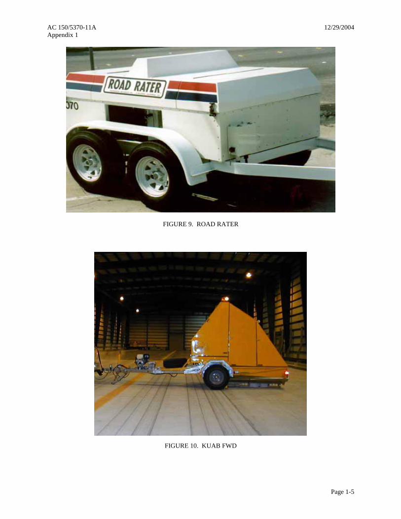
AC 150/5370-11A 12/29/2004 Appendix 1
Page 1-5
FIGURE 9. ROAD RATER
FIGURE 10. KUAB FWD

AC 150/5370-11A 12/29/2004 Appendix 1
Page 1-6
FIGURE 11. DYNATEST FWD
FIGURE 12: CARL BRO FWD/HWD AND LWD TRAILER, VAN-INTEGRATED OR PORTABLE)

AC 150/5370-11A 12/29/2004 Appendix 1
FIGURE 13. JILS HWD
FIGURE 14. EVALUATION OF HWD FORCE LINEARITY IN TERMS OF ISM
0
500
1,000
1,500
2,000
2,500
1
Test Item
ISM
(k/in
)
LFS MFS
HFS
LFSMFS
HFS
Applied Force12, 24, 36 kip
Page 1-7

AC 150/5370-11A 12/29/2004 Appendix 1
Page 1-8
FIGURE 15. EVALUATION OF HWD FORCE LINEARITY IN TERMS OF SUBGRADE ELASTIC MODULUS
D1
Transverse Joint
D1
Center of Slab
D1D1
Slab Corner Longitudinal Joint
Direction of Testing
FIGURE 16. NDT TEST LOCATIONS WITHIN A PCC SLAB
12, 24, 36 kip Applied Force
0
5,000
10,000
15,000
20,000
25,000
30,000
35,000
40,000
1
Test Item
Sub
grad
e M
odul
us (p
si)
LFS
MFS
HFS
LFS
MFS
HFS
Applied Force12, 24, 36 kip

AC 150/5370-11A 12/29/2004 Appendix 1
Page 1-9
Aircraft Wheel
Loaded PCC Slab Unloaded PCC Slab
FIGURE 17. ILLUSTRATION OF LOAD TRANSFER ACROSS A PCC JOINT
Taxiway or Runway Centerline
Direction of Testing
Station 0+00
PCC Lane 2
PCC Lane 1
PCC Lane 4
PCC Lane 3
9.2
3.1
1.2 3.2
1.12.1
2.2
4.1
4.2
NOTE: First number indicates PCC lane number; second number indicates location within lane (e.g., along slab center or slab joint).
FIGURE 18. EXAMPLE RUNWAY OR TAXIWAY SKETCH WHEN CENTERLINE LIES ON SLAB JOINT

AC 150/5370-11A 12/29/2004 Appendix 1
Page 1-10
Taxiway or Runway Centerline
Direction of Testing
Station 0+00
PCC Lane 2
PCC Lane 9
PCC Lane 1
2.2
1.1
1.2 3.2
9.12.1
4.2
NOTE: First number indicates PCC lane number; second number indicates location within lane (e.g., along slab center or slab joint).
FIGURE 19. EXAMPLE RUNWAY OR TAXIWAY SKETCH WHEN CENTERLINE
DOES NOT LIE ON SLAB JOINT
Taxiway or Runway Centerline
Direction ofTesting
Station 0+00
1.19.12.14.1 3.1 NOTE: First number indicates HMA lane number; second number indicates a "center" test for HMA pavements.
FIGURE 20. EXAMPLE RUNWAY OR TAXIWAY SKETCH FOR HMA PAVEMENTS

AC 150/5370-11A 12/29/2004 Appendix 1
Page 1-11
Positive (daytime) curling
Negative (nighttime) curling
Thermal Curling
FIGURE 21. THERMAL CURLING IN PCC SLAB FROM TEMPERATURE CHANGES
Slab CenterTest
Direction of Testing
TransverseJoint Test
Slab CornerTest
LongitudinalJoint Test
Plate
Plate
Plate
Plate
FIGURE 22. LOCATION OF ADDITIONAL SENSORS FOR CORNER AND JOINT TESTING

AC 150/5370-11A 12/29/2004 Appendix 1
Page 1-12
Process and Group Raw
Deflection Data byPavement Facility
Conduct Preliminary Analysisby Normalizing Deflections
and Computing ISM
Separate Facility RawDeflection Data into
Pavement Section Subsets
Conduct Analysis to ObtainDesired Pavement
Characteristics
Pavement Layer StrengthBack-calculate Elastic
Modulus Values
Joint/Crack ConditionCompute Load Transfer
Efficiency
Material DurabilityDetermine Extent of
Material Deterioration
Support ConditionsDetermine if Voids
Exist Under PCC Slab
Statistically DetermineDesign and Evaluation Inputs
Structural CapacityDetermine Allowable
Loads and Remaining Life
Rehabilitation DesignDevelop Overlay and
Reconstructed Cross-sections
Airport Pavement ManagementDevelop Criteria to Supplement PCI
in Capital Program Development
FIGURE 23. NDT DATA ANALYSIS AND DESIGN FLOWCHART
0
1,000
2,000
3,000
4,000
5,000
6,000
7,000
0 500 (150)
1,000 (300)
1,500 (455)
2,000 (600)
2,500 (760)
3,000 (900)
3,500(1060)
4,000(1200)
4,500(1370)
5,000(1525)
5,500(1675)
6,000(1825)
6,500(1980)
7,000(2130)
7,500(2285)
8,000(2435)
8,500(2590)
STATION, STA ft. (m)
ISM
, (k/
in)
SECTION 1 SECTION 4SECTION 3SECTION 2
8in(200mm)HMA12in(300mm)stab. base6in(150 mm)stab. subgr
5in(125mm) HMA15in(375mm) stab. base
5in(125mm) HMA28in(700mm) aggregate base
5in(125 mm) HMA16in(400 mm) aggregate base
Note: Bold bars indicate theaverage ISM value for eachsection.
FIGURE 24. ISM PLOT USED TO IDENTIFY PAVEMENT SECTION BREAKS

AC 150/5370-11A 12/29/2004 Appendix 1
Page 1-13
0
5
10
15
20
25
30
35
0 500 (150)
1,000 (300)
1,500 (455)
2,000 (600)
2,500 (760)
3,000 (900)
3,500(1060)
4,000(1200)
4,500(1370)
5,000(1520)
5,500(1675)
6,000(1825)
6,500(1980)
7,000(2130)
7,500(2285)
8,000(2435)
8,500(2590)
STATION, STA ft. (m)
20-k
ip N
orm
aliz
ed D
1, (m
ils)
SECTION 1 SECTION 4SECTION 3SECTION 2
8in(200mm) HMA12in(300mm) stab. base 6in(150mm) stab. subgr.
5in(125mm) HMA15in(375mm) stab. base
5in(125mm) HMA28in(700mm) aggregate base
5in(125mm) HMA 16in(400mm) aggregate base
Note: Bold bars indicate theaverage normalized deflectionvalue under the load plate for eachsection.
FIGURE 25. NORMALIZED DEFLECTION PLOT USED TO IDENTIFY PAVEMENT SECTION BREAKS
0
2
4
6
8
10
12
14
0 500 (150)
1,000 (300)
1,500 (455)
2,000 (600)
2,500 (760)
3,000 (900)
3,500(1060)
4,000(1200)
4,500(1370)
5,000(1520)
5,500(1675)
6,000(1825)
6,500(1980)
7,000(2130)
7,500(2285)
8,000(2435)
8,500(2590
STATION, STA ft. (m)
20-k
ip N
orm
aliz
ed D
4, (m
ils)
SECTION 1 SECTION 4SECTION 3SECTION 2
8in(200mm) HMA12in(300mm) stab. base 6in(150mm) stab. subgr.
5in(125mm) HMA15in(375mm stab. base
5in(125mm) HMA28in(700mm) aggregate base
5in(125mm) HMA16in(400mm) aggregate base
Note: Bold bars indicate theaverage normalized deflection
value 24 inches (600 mm) from the loadplate for each section.
FIGURE 26. NORMALIZED SUBGRADE DEFLECTION PLOT
USED TO IDENTIFY PAVEMENT SECTIONS

AC 150/5370-11A 12/29/2004 Appendix 1
Page 1-14
Remove Basin DeflectionData with Type I, II, or III
Errors
Identify Pavement Type fromSection Construction History
Compare Layer ThicknessesFrom Cores, Borings, and
Construction History
Select Back-calculation MethodBased on Pavement Type
HMA PavementsIterative Elastic LayerAASHTO Closed-Form
PCC PavementsIterative Elastic LayerAREA Closed-Form
Thick HMA Overlays on PCCIterative Elastic Layer
Thin HMA Overlays on PCCIterative Elastic LayerAREA Closed-Form
FIGURE 27. PROCESS FOR DATA PREPARATION AND BACK-CALCULATION METHOD SELECTION
Calculate AREA Based on NDT Sensor Configuration and
Pavement Type
PCC Pavements (<16in(400mm) thick AREA Equation 3 AREA Equation 4
HMA Overlaid PCC AREA Equation 5 AREA Equation 6
PCC Pavements (> 16in(400mm) thick AREA Equation 5 AREA Equation 6
Calculate Radius of Relative Stiffness from Equation 8
Calculate Modulus of Subgrade Reaction, k, from Equation 9
Calculate Effective Elastic Modulus Above Subgrade from Equation 10
Apply PCC Slab Size Correction Factor to Modulus and k-value
Bonded PCC or HMA OL, or St. Base
Equatio n 12 Equation 13 Static k - value = ½ back - calculated k
No Overlay or Stabilized Base
Effective Modulus Equals PCC Modulus of Elasticity Static k-value = ½ back-calc. k
Unbonded PCC or HMA OL, or St. Base
Equation 14 Static k-value = ½ back - calculated k
Split Effective Modulus as Required Based on Overlay (OL) and Base Type
FIGURE 28. FLOWCHART FOR CLOSED-FORM BACK-CALCULATION USING AREA METHOD

AC 150/5370-11A 12/29/2004 Appendix 1
Page 1-15
12 inches (300 mm)
LOAD PLATE
24 inches (600 mm)
36 inches (90 mm)
D0
D0
Basin AREA
D12
D0
D24
D0
D36
D0
⎟⎟⎠
⎞⎜⎜⎝
⎛+⎟⎟
⎠
⎞⎜⎜⎝
⎛+⎟⎟
⎠
⎞⎜⎜⎝
⎛+=
0
36
0
24
0
12 612126)(DD
DD
DD
inAREA
FIGURE 29. ILLUSTRATION OF BASIN AREA FOR SHRP FOUR-SENSOR CONFIGURATION
MEASUREDCALCULATED
E1
E3
E2
FIGURE 30. COMPARISON OF MEASURED AND CALCULATED DEFLECTION BASINS

AC 150/5370-11A 12/29/2004 Appendix 1
Page 1-16
Compare Layer Thicknesses from Cores, Borings, and
Construction History
Identify Potential Problem Layers 1. Thin layers (<3 inches (75mm) thick) 2. More than 3 layers 3. Soft layer above strong layer 4. Soft layer between 2 strong layers 5. Depth to stiff layer (<10 ft. (3.0 m))
Determine Elastic Modulus “Seed Values” for each Layer
Determine Depth to Bedrock or Apparent Stiff Layer
Determine the Initial Pavement Cross-section and Layer
Thicknesses
Adjust Cross-section, Layer Thicknesses, and Modulus
Limits as Necessary
Review Back - Calculation Results 1. Are the error levels within limits? 2. Are the modulus values reasonable? 3. For any layer, is the upper modulus limit being hit often for each basin? 4. For any layer, is the lower modulus limit being hit often for each basin? 5. Are moduli ratios between adjacent unbound layers unrealistic?
Compute Statistical Summary of Results for Each Layer
Run Elastic Layer Back - calculation Software Program
Results OK?
Yes No
FIGURE 31. BACK-CALCULATION PROCEDURES FOR AN ELASTIC LAYER BASED ANALYSIS

AC 150/5370-11A 12/29/2004 Appendix 1
Page 1-17
FIGURE 32. INITIAL BAKFAA RUN FOR EXAMPLE 2
FIGURE 33. SECOND BAKFAA RUN FOR EXAMPLE 2

AC 150/5370-11A 12/29/2004 Appendix 1
Page 1-18
FIGURE 34. OUTPUT FROM SECOND BAKFAA RUN FOR EXAMPLE 2
FIGURE 35. DEFLECTION VS. STRESS LTE RELATIONSHIP FOR 12-INCH (300 mm)
DIAMETER LOAD PLATE
0
10
20
30
40
50
60
70
80
90
100
0 10 20 30 40 70 80 90 100
Stress LTE (%)
Def
lect
ion
LT
E (
%)
Radius of Relative Stiff=20in(500mm)Radius of Relative Stiff=130in(3300mm)
25 % Stress LTE is FAA TargetV l

AC 150/5370-11A 12/29/2004 Appendix 1
Page 1-19
0%
10%
20%
30%
40%
50%
60%
70%
80%
90%
100%
0+00 20+00 40+00 60+00 80+00 100+00 120+00
Station
Tran
sver
se Jo
int L
TE
NDT Lane 1-12ft(3.6m) right of CL
NDT Lane 2-12ft(3.6m) left of CL
LTE Acceptable
LTE Poor
LTE Fair
Section 1 Section 2 Section 3 Section 4
FIGURE 36. EXAMPLE PLOT OF TRANSVERSE JOINT ∆LTE FOR A 10,000-FOOT (3,050 m) TAXIWAY
LINE A - NO VOIDSLINE B - SMALL VOIDLINE C - LARGE VOID
0 2 4 6 8 10 12 14 16 18 20 22 24 26 28 30 32 34 36 38 40
0
5
10
15
20
25
MAXIMUM PAVEMENT DEFLECTION (mils)HWD CORNER LOAD (kips)
FIGURE 37. VOID DETECTION BENEATH PCC SLABS

AC 150/5370-11A 12/29/2004 Appendix 1
Page 1-20
-5
-3
-1
1
3
5
7
9
11
13
15
0+00 10+00 20+00 30+00 40+00 50+00 60+00 70+00 80+00 90+00 100+00 110+00 120+00
Station
Voi
ds, m
ils
NDT Lane 1-12ft(3.6m) right of CLNDT Lane 2-12ft(3.6m) left of CL
Voids Present
Voids Present
No Voids
FIGURE 38. EXAMPLE PLOT OF TRANSVERSE JOINT VOIDS FOR A 10,000-FOOT (3,050 m) TAXIWAY
0.00
0.50
1.00
1.50
2.00
2.50
3.00
3.50
4.00
4.50
5.00
0+00 10+00 20+00 30+00 40+00 50+00 60+00 70+00 80+00
Station
ISM
Cen
ter t
o Ed
ge R
atio
NDT Lane 1-10ft(3.0m) right of CL
NDT Lane 2-10ft(3.0m) left of CL
NDT Lane 3-20ft(6.09m) right of CL
NDT Lane 4-20ft(6.09m) left of CLUnderlying PCC is infair to poor condition
Underlying PCC is ingood condition
Underlying PCC is inexcellent condition
FIGURE 39. EXAMPLE PLOT OF ISMratio FOR TRANSVERSE JOINT FOR HMA OVERLAID PCC

AC 150/5370-11A 12/29/2004 Appendix 1
Page 1-21
1
9
18
14 14
4
2 23
0
2
4
6
8
10
12
14
16
18
20
1182 1484 1787 2090 2392 2695 2998 3300 >3300
ISM (k/in)
Freq
uenc
y (N
DT
Test
Loc
atio
ns)
MeanMedian
FIGURE 40. HISTOGRAM OF ISM VALUES FOR SECTION 3 IN FIGURE 24

AC 150/5370-11A 12/29/2004 Appendix 2
Page 2-1
APPENDIX 2-TABLES
TABLE 1. SUMMARY OF NONDESTRUCTIVE TESTING MEASURING EQUIPMENT
Category Equipment Manufacturer Load range, lbs. (kN)
Load transmitted by, in. (mm)
Number of sensors
Sensor spacing, in. (mm)
Benkleman Beam Soiltest, Inc. Vehicle dependent
Loaded truck or aircraft 1 NA
La Croix Deflectograph Switzerland Vehicle
dependent Loaded truck 1 NA Static
Plate-bearing test Several,
ASTM D 1196
Vehicle dependent Loaded truck 1 NA
Dynaflect Geolog, Inc. 1,000 (5)
15 (2,400) diameter steel
wheels 4
Variable, 0 to 48
(0 to 1,200)
Road Rater Foundation Mechanics,
Inc.
500 to 8,000 (2 to 35)
18 (450) diameter plate 4 to 7
Variable, 0 to 48
(0 to 1,200) Vibratory
WES Heavy Vibrator
U.S. Corps of Engineers
500 to 30,000 (2 to 130)
18 (450) diameter plate 5
Variable, 0 to 60
(0 to 1,500)
Dynatest FWD Dynatest Engineering
1,500 to 27,000(7 to 120)
12 or 18 (300 or 450)
diameter plate 7 to 9
Variable, 0 to 90
(0 to 2,250)
Dynatest HWD Dynatest Engineering
6,000 to 54,000 (27 to 240)
12 or 18 (300 or 450)
diameter plate 7 to 9
Variable, 0 to 90
(0 to 2,250)
JILS FWD Foundation Mechanics,
Inc.
1,500 to 24,000 (7 to 107)
12 or 18 (300 or 450)
diameter plate 7
Variable, 0 to 96
(0 to 2,400)
JILS HWD Foundation Mechanics,
Inc.
6,000 to 54,000 (27 to 240)
12 or 18 (300 or 450)
diameter plate 7
Variable, 0 to 96
(0 to 2,400)
KUAB FWD KUAB 1,500 to 34,000 (7 to 150)
12 or 18 (300 or 450)
diameter plate 7
Variable, 0 to 72
(0 to 1,800)
KUAB HWD KUAB 3,000 to 66,000 (13 to 294)
12 or 18 (300 or 450)
diameter plate 7
Variable, 0 to 72
(0 to 1,800) Carl Bro FWD Carl Bro Group 1,500 to 34,000
(7 to 150) 12 or 18
(300 or 450) diameter plate
9 to 12 Variable, 0 to 100
(0 to 2,500) Carl Bro HWD Carl Bro Group 1,500 to 56,000
(7 to 250) 12 or 18
(300 or 450) diameter plate
9 to 12 Variable, 0 to 100
(0 to 2,500)
Impulse
Carl Bro LWD Carl Bro Group 225 to 3,400 (1 to 15)
4 or 8 or 12 (100 or 200 or 300)
diameter plate
1 to 3 Variable, 0 to 40
(0 to 1,000)
NOTE: EQUIPMENT MENTIONED ABOVE IS FOR INFORMATION PURPOSES, ONLY.

AC 150/5370-11A 12/29/2004 Appendix 2
Page 2-2
TABLE 2. DETAILED SPECIFICATIONS FOR SELECTED FWDS AND HWDS
Equipment manufacturer Equipment Specifications Dynatest Foundation
Mechanics, Inc. KUAB Carl Bro Group
Load range, lbs (kN) 1,500 to 54,000 (7 to 240)
1,500 to 54,000 (7 to 240)
1,500 to 66,000 (7 to 294)
1,500 to 56,000 (7 to 250)
Load duration 25 to 30 millisecond Selectable 56 millisecond 25 to 30 millisecond Load rise time Variable Selectable 28 millisecond 12 to 15 millisecond Load generator One-mass One-mass Two-mass One-mass
Type of load plate Rigid with
rubberized pad or split plate
Rigid with rubberized pad
Segmented or nonsegmented with
rubberized pads
Four segmented plate with rubberized pad
Diameter of load plate, in. (mm)
12 and 18 (300 and 450)
12 and 18 (300 and 450)
12 and 18 (300 and 450)
12 and 18 (300 and 450)
Type of deflection sensors
Geophones with or without dynamic calibration device
Geophones Seismometers with
static field calibration device
Geophones with our without dynamic calibration device
Deflection sensor positions, in. (mm)
0 to 90 (0 to 2250)
0 to 96 (0 to 2400)
0 to 72 (0 to 1800)
0 to 96 (0 to 2500)
Number of sensors 7 to 9 7 7 9 to 12
Deflection sensor range Mils (mm)
80 or 100
(2 or 2.5 mm) 80 (2) 200 (5) 90 (2.2)
Deflection resolution 1 µm (0.04 mils) 1 µm (0.04 mils) 1 µm (0.04 mils) 1 ìm (0.04 mils) Relative accuracy of deflection sensors 2 µm ± 2% 2 µm ± 2% 2 µm ± 2% 2 ìm ± 2%
Test time required (four loads) 25 seconds 30 seconds 35 seconds 20 seconds
Type of computer Personal computer Personal computer Personal computer Personal computer
TABLE 3. ASTM STANDARDS FOR DEFLECTION MEASURING EQUIPMENT
NDT equipment type ASTM
Static Vibratory Impulse
D 1195, Standard Test Method for Repetitive Static Plate Load Tests of Soils and Flexible Pavement Components, for Use in Evaluation and Design of Airport and Highway Pavements
●
D 1196, Standard Test Method for Nonrepetitive Static Plate Load Tests of Soils and Flexible Pavement Components, for Use in Evaluation and Design of Airport and Highway Pavements
●
D 4602, Standard Guide for Nondestructive Testing of Pavements Using Cyclic-Loading Dynamic Deflection Equipment ●
D 4694, Standard Test Method for Deflections with A Falling-Weight-Type Impulse Load Device ●
D 4695, Standard Guide for General Pavement Deflection Measurements ● ● ●

AC 150/5370-11A 12/29/2004 Appendix 2
Page 2-3
TABLE 4. COMMON SENSOR CONFIGURATIONS
Sensor distance from center of load plate, inches (mm) Agency Configuration name Sensor1 Sensor2 Sensor3 Sensor4 Sensor5 Sensor6 Sensor7
U.S. Air Force AF 7-Sensor 0 12 (300)
24 (600)
36 (900)
48 (1,200)
60 (1,500)
72 (1,800)
SHRP
4-Sensor 0 12 (300)
24 (600)
36 (90) FHWA & State
DOTs SHRP 7-Sensor 0 6
(150) 12
(300) 18
(450) 24
(600) 36
(900) 60
(1,500)
TABLE 5. TYPICAL RUNWAY AND TAXIWAY TEST LOCATIONS AND SPACING, FEET (m)
Jointed PCC and HMA overlaid PCC HMA Project level Network level Project level Network level Test type
Offset, ft. (m) Spacing, ft. (m) Offset,
ft. (m) Spacing, ft. (m)
Offset, ft. (m) Spacing, ft. (m) Offset,
ft. (m) Spacing, ft. (m)
Center 10 (3) 30 (9)
65 (20)
100 (30) 100-200 (30-60)
400 (120) 10 (3) 200-400
(60-120)
10 (3) 20 (6)
65 (20)
100 (30) 100-200 (30-60)
200-400 (60-120) 10 (3) 200-400
(60-120)
Transverse Joint
10 (3) 30 (9)
65 (20)
100-200 (30-60) 200-400 (60-120)
400 (120) 10 (3) 400
(120)
Longitudinal Joint
20 (6) 40 (12) 60 (18)
200 (60) 400 (120) 400 (120)
Corner 20 (6)
40 (12) 60 (18)
200 (60) 400 (120) 400 (120)
NOTE: For each centerline offset, there are two NDT passes, one to the left and one to the right; spacing is staggered between adjacent NDT passes; and a minimum of two NDT tests should be conducted per pavement section.
TABLE 6. TYPICAL APRON TEST LOCATIONS AND FREQUENCY
Jointed PCC and HMA overlaid PCC HMA, ft 2 (m2) Test type Project level Network level Project level Network level
Center 1 test for every 10 to 20 slabs
1 test for every 30 to 60 slabs
1 test for every 1,970 to 4,000 (600 to 1200)
1 test for every 5,750 to 11,490 (1750 to 3,500)
Transverse Joint
1 test for every 10 to 40 slabs
1 test for every 60 slabs
Longitudinal Joint
1 test for every 20 to 40 slabs
1 test for every 60 slabs
Corner 1 test for every 20 to 40 slabs

AC 150/5370-11A 12/29/2004 Appendix 2
Page 2-4
TABLE 7. FAA SOFTWARE TOOLS FOR PAVEMENT ANALYSIS, EVALUATION, AND DESIGN
NDT data analysis Evaluation1 Design Tool function BAKFAA FEAFAA COMFAA LEDFAA F806FAA R805FAA
Back-calculate HMA moduli ●
Back-calculate PCC moduli ●
Back-calculate APC2 moduli ●
Compute load transfer ●
Conduct void analysis ●
Compute allowable loads ● ● ● ● ●
Compute remaining life ● ● ●
Compute PCN ●
Perform HMA overlay design ● ●
Perform PCC overlay design ● ●
Design new HMA cross-section ● ●
Design PCC Cross-section ● ●
NOTES: 1 These evaluation tools can be used for design checks but are not approved FAA design programs. 2 APC is asphalt overlaid PCC pavements.
TABLE 8. THEORETICAL BASIS OF FAA SOFTWARE TOOLS
Structural Theory Winkler Foundation FAA Tool CBR Elastic Layer Westergaard Finite Element
BAKFAA ● FEAFAA ● COMFAA ● ● LEDFAA ● F806FAA ● R805FAA ●
NOTE: These programs can be downloaded from the FAA’s website at www.faa.gov.

AC 150/5370-11A 12/29/2004 Appendix 2
Page 2-5
TABLE 9. REQUIRED SENSOR DISTANCE (INCH) FROM LOAD PLATE WITH
12-INCH (300 MM) DIAMETER
Subgrade CBR Surface Type Surface Layer Thickness, in (mm) 4 (Weak) 12 (Average) 20 (Strong)
4 (100 mm) 15 12 9 HMA 8 (200 mm) 30 24 18 12 (300 mm) 84 60 48 PCC 20(500 mm) 144 108 84
NOTE: The shaded areas show the required sensor distance beyond the typical NDT equipment maximum of 70 inches (1,775 mm).
TABLE 10. TYPE OF BACK-CALCULATION SOFTWARE TOOL THAT IS REQUIRED FOR EACH LOAD SCENARIO
Type of load application Material response
Static Dynamic Linear Closed-form and iteration-based tools Finite-element tools Nonlinear Iteration-based tools Finite-element tools
NOTE: Dynamic loads include those generated by vibratory and impulse load NDT equipment.
TABLE 11. AREA-BASED CONSTANTS FOR EQUATION 8
Constant Area method A B C D
1. SHRP 4-sensor (0 to 36 inches (0 to 900mm)
36 1812.279 -2.559 4.387
2. SHRP 7-sensor (0 to 60 inches (0 to 1,500mm)
60 289.078 -0.698 2.566
3. SHRP 5 outer sensors (12 to 60 inches (300 to 1,500mm)
48 158.408 -0.476 2.220
4. Air Force 6 outer sensors (12 to 72 inches (300 to 1,800mm)
60 301.800 -0.622 2.501
TABLE 12. CONSTANTS FOR *rd (EQUATION 11)
Constant Radial distance from
load plate, in. (mm) x y z 0 0.12450 0.14707 0.07565
12 (300) 0.12188 0.79432 0.07074

AC 150/5370-11A 12/29/2004 Appendix 2
Page 2-6
TABLE 13. TYPICAL MODULUS VALUES AND RANGES FOR PAVING MATERIALS
Material Low value, psi (MPa) Typical value, psi/MPa High value, psi/MPa Asphalt concrete 70,000 (483) 500,000 (3447) 2,000,000 (13790) Portland cement concrete 1,000,000 (6895) 5,000,000 (34474) 9,000,000 (62053) Lean-concrete base 1,000,000 (6895) 2,000,000 (13790) 3,000,000 (20684) Asphalt-treated base 100,000 (689) 500,000 (3447) 1,500,000 (10342) Cement-treated base 200,000 (1379) 750,000 (5171) 2,000,000 (13790) Granular base 10,000 (69) 30,000 (207) 50,000 (345) Granular subbase or soil 5,000 (34) 15,000 (103) 30,000 (207) Stabilized soil 10,000 (69) 50,000 (345) 200,000 (1379) Cohesive soil 3,000 (21) 7,000 (48) 25,000 (172)
TABLE 14. TYPICAL POISSON'S RATIOS FOR PAVING MATERIALS
Material Low value High value Asphalt concrete or asphalt-treated base 0.25 0.40 Portland cement concrete 0.10 0.20 Lean concrete or cement-treated base 0.15 0.25 Granular base, subbase, or soil 0.20 0.40 Stabilized soil 0.15 0.30 Cohesive soil 0.30 0.45

AC 150/5370-11A 12/29/2004 Appendix 2
Page 2-7
TABLE 15. LINEAR ANALYSIS BACK-CALCULATION PROGRAMS
Program name
Developed by
Calculation subroutine
Rigid layer analysis
Layer interface analysis
Maximum number of layers
Convergence routine
BAKFAA FAA LEAF Yes Variable 10 rms
BISDEF
U.S. Army Corps of
Engineers - WES
BISAR Proprietary Yes Variable
Cannot exceed no. of deflections. Works
best for three unknowns
Sum of sq. of absolute
error
CHEVDEF
U.S. Army Corps of
Engineers - WES
CHEVRON Yes Fixed (rough)
Cannot exceed no. of deflections. Works
best for three unknowns.
Sum of sq. of absolute
error
ELSDEF
Texas A&M Univ.; U.S. Army Corps of Engineers
- WES
ELSYM5 Yes Fixed (rough)
Cannot exceed no. of deflections. Works
best for three unknowns
Sum of sq. of absolute
error
MODULUS Texas Trans Institute WESLEA Yes
Variable Fixed Up to four unknowns, plus stiff layer
Sum of relative sq.
error
WESDEF
U.S. Army Corps of
Engineers - WES
WESLEA Yes Variable Up to five layers Sum of sq. of
absolute error
MICHBAK Michigan State CHEVRON Yes Fixed Up to four unknowns,
plus stiff layer
Sum of relative sq.
error NOTES: All programs use multilayer elastic theory during the back-calculation. All programs, except MODULUS, use an iterative back-calculation method; MODULUS uses a database format. “Seed” moduli are required for all programs. A range of acceptable modulus values is required for all programs, except MICHBAK. All programs allow the user to fix the modulus value for a layer. All programs contain an error convergence function.

AC 150/5370-11A 12/29/2004 Appendix 2
Page 2-8
TABLE 16. NONLINEAR ANALYSIS BACK-CALCULATION PROGRAMS
Program name Developed by
Calculation subroutine
Rigid layer analysis
Layer interface analysis
Maximum number of layers Convergence routine
BOUSDEF Zhou, et.al.
Oregon State Univ.
Odemark-Boussinesq
Yes Fixed
(rough) Five, works best for
three unknowns. Sum of percent errors
ELMOD/ ELCON
P. Ullidtz, Dynatest
Odemark-Boussinesq
Yes Variable
Fixed (rough)
Up to four, excluding rigid
layer
Relative error on five sensors
EMOD PCS/LAW CHEVRON No Fixed (rough) Three Sum of relative sq.
error
EVERCALC J. Mahoney et al. CHEVRON Yes Fixed
(rough) Three, excluding
layer Sum of absolute error
FREDDI W. Uddin BASINPT Yes Variable
Fixed (rough) Unknown Unknown
ISSEM4 R. Stubstad ELSYM5 No Fixed (rough) Four Relative deflections
error
MOD-COMP3 L. Irwin, Szebenyi CHEVRON Yes Fixed
(rough)
Two to 15 layers, max. five unknown
layers
Relative deflections error at sensors
PADAL S.F. Brown et.al Unknown Unknown Fixed Unknown Sum of relative sq.
error RoSy DESIGN Carl Bro
Group Odemark-
Boussinesq No Fixed
(rough) Up to four layers Relative error on six
sensors NOTES: All programs, except BOUSDEF and ELMOD/ELCON, use multilayer elastic theory during the
back-calculation; BOUDEF and ELMOD/ELCON use Odemark-Boussinesq. All programs use an iterative back-calculation method. Nonlinear analysis for ELMOD/ELCON, EMOD, and PADA is limited to the subgrade. “Seed” moduli are required for all programs, except ELMOD/ELCON and FREDDI. With the exception of ELMOD/ELCON, a range of acceptable modulus values is required. Unknown for FREDDI and PADA. All programs allow users to fix the modulus value for a layer; unknown for FREDDI and PADA. Only BOUSDEF contains an error convergence function; unknown for PADA.
TABLE 17. SEED MODULUS AND POISSON'S RATIOS FOR EXAMPLE PROBLEM 2
Layer Low value, psi (MPa)
Typical value, psi (MPa)
High value, psi (MPa)
Poisson's Ratio
5-inch (125 mm) HMA (E1) 70,000 (483)
500,000 (3447)
2,000,000 (13790) 0.35
16-inch (400 mm) aggregate base (E2)
10,000 (69)
30,000 (207)
50,000 (345) 0.40
Granular soil (E3) 5,000 (34)
15,000 (103)
30,000 (207) 0.40
Bedrock Layer (E4) 1,000,000 (6895)
1,000,000 (6895)
1,000,000 (6895) 0.50

AC 150/5370-11A 12/29/2004 Appendix 2
Page 2-9
TABLE 18. PAVEMENT JOINT PERFORMANCE RATINGS
Radius of relative stiffness, kλ ∆LTE , percent
20 inches (500 mm) 130 inches (3,300 mm) 90 to 100 Acceptable Acceptable 70 to 90 Acceptable Fair 50 to 70 Fair Poor
Less than 50 Poor Poor
TABLE 19. STATISTICAL SUMMARY OF ISM VALUES FOR EACH SECTION IN FIGURE 24
Section Mean, k./in. St.Dev. k./in. Cv, percent Mean minus 1 St.Dev., k./in.
1 4,505 1,016 22.6 3,489 2 896 126 14.2 770 3 2,010 560 27.7 1,450 4 1,290 280 21.7 1,010

AC 150/5370-11A 12/29/2004 Appendix 2
Page 2-10
TABLE 20. REQUIRED FAA ADVISORY CIRCULAR EVALUATION AND DESIGN INPUTS
AC 150/5320-6 Required analysis inputs
Analysis type
Common input sources LEDFAA F806FAA R805FAA
FE, RE, OF, OR NDT modulus, lab tests ● 1. HMA or PCC
surface layer elastic moduli FD, RD
Lab mix design ●
FE, RE, OF, OR NDT modulus, lab tests ● 2. Stabilized
base/subbase layer elastic moduli FD, RD
Lab mix design ●
FE, RE, OF, OR NDT modulus, DCP, lab tests ● 3. Granular
base/subbase layer elastic moduli FD, RD
Lab tests ●
4. Subgrade elastic moduli
All types
NDT modulus, DCP, lab tests, field tests ●
5. Subgrade modulus, k
RE, RD, OR NDT modulus, field tests ●
6. Unbound layer and subgrade CBR
All types
NDT modulus correlation, DCP, lab tests, field tests ●
7. Base/subbase equivalency factors
FE, FD, OF
NDT modulus correlation, specified in AC 150/5320-6 ●
RE, OR NDT modulus correlation, lab mix design, lab split tensile ● ● 8. PCC modulus of
rupture RD Lab mix design ● ● 9. PCC Cb, Cr overlay factors OR NDT results, illustrations in
AC 150/5320-6 ●
10. PCC SCI overlay factor OR NDT results, PCI results per
ASTM D 5340 ●
11. Existing layer thicknesses
FE, RE, OF, OR Cores, borings, DCP, GPR ● ● ●
FE, FD, RD
Always assumed to be bonded in AC 150-5320-6 ●
RE, OR As specified in AC 150/5320-6 ● ● 12. Layer interface
bonding condition
OF Rigid unbonded & flexible bonded per AC 150/5320-6 ●
13. Aircraft models, weights, annual operations
All types
Airport records, master plans, field observations ● ● ●
14. Design life FD, RD, OF, OR
20 years per AC 150/5320-6, 1 to 50 years per AC 150/5320-6 Chapter 7, as approved
● ● ●
15. Targeted remaining life FE, RE As specified by airport owner
with aircraft weight restriction ● ● ●
NOTES: FE and RE are flexible and rigid evaluation, respectively. FD and RD are flexible and rigid design, respectively. OF is overlays on flexible pavement. OR is overlays on rigid pavement. A past records review should always be the first source of information. Frost considerations and swelling soils are addressed in AC 150/5320-6.

AC 150/5370-11A 12/29/2004 Appendix 2
Page 2-11
TABLE 21. ALLOWABLE MODULUS VALUES FOR LEDFAA (AC 150/5320-6), psi (MPa)
Layer type FAA specified layer Rigid pavement Flexible pavement P-501 PCC 4,000,000 (27579) Surface P-401 HMA 200,000 (1379) P-401 HMA 400,000 (2758) Variable stabilized (flexible) 150,000 to 400,000 (1034 to 2758) Variable stabilized (rigid) 250,000 to 700,000 (1724 to 4826) P-306 econocrete 700,000 (4826) P-304 cement treated base 500,000 (3447)
Stabilized base and subbase
P-301 soil cement 250,000 (1724) P-209 crushed aggregate 75,000 (517) Granular base
and subbase P-154 uncrushed aggregate 40,000 (276)
Subgrade Subgrade 1,000 to 50,000 (7 to 345) Undefined Undefined layer 1,000 to 4,000,000 (7 to 27579)
NOTE: Initial values are automatically adjusted during analysis based on the moduli of lower layers and layer thicknesses; nonstandard FAA layer.
TABLE 22. HMA PAVEMENT BASE AND SUBBASE MODULUS AND EQUIVALENCY FACTOR INPUTS
Layer type Back-calculated modulus value,
psi (MPa)
AC 150/5320-6, Chapter 7 input moduli (LEDFAA),
psi (MPa)
AC 150/5320-6 equivalency factors
> 400,000 (2758) 400,000 (2758) 1.6
150,000 to 400,000 (1034 to 2758) Back-calculated value
Interpret between 1.2 and 1.6 using back-calculated
value
Stabilized base1 and subbase for flexible pavement
< 150,000 (1034) 150,000 (1034) 1.2 > 700,000 (4826) 700,000 (4826) 1.6
250,000 to 700,000 (1724 to 4826) Back-calculated value N.A.
Cement stabilized base1 and subbase for rigid pavement
< 250,000 (1724) 250,000 (1724) N.A. > 40,000 (276) Use P-209 layer 1.0 Granular base and
subbase ≤ 40,000 (276) Use P-154 layer 1.0 NOTE: 1Equivalency factors are based on a P-209 granular base in 150/5320-6.
TABLE 23. RECOMMENDED REDUCED VALUES FOR LOSS OF SUPPORT CONDITIONS
Statistically selected back-calculated k-value (static) Percent of slabs with void depth >
3 mils k < 100 100 ≤ k < 300 k ≥ 300
0 ≤ % < 10 50 75 100 10 ≤ % < 25 40 60 80
25 ≤ % < 100 25 40 55

AC 150/5370-11A 12/29/2004 Appendix 3
Page 3-1
APPENDIX 3-GLOSSARY
AASHTO American Association of State Highway and Transportation AC Advisory Circular ACN Airport Classification Number AGBS Aggregate Base AOA Airport Operations Area APC Asphalt Overlaid PCC Pavements APMS Airport Pavement Management System ASTM American Society for Testing and Materials CBR California Bearing Ratio CIP Capital Improvement Program CL Centerline COV Coefficient of Variations CTB Cement Treated Base DCP Dynamic Cone Penetrometer DIA Denver International Airport, CO DSM Dynamic Stiffness Modulus FAA Federal Aviation Administration FHWA Federal Highway Administration FWD Falling Weight Deflectometer GA General Aviation GPR Ground-Penetrating Radar HMA Asphalt HWD Heavy-Falling Weight Deflectometer IR Infrared Thermography ISM Impulse Stiffness Modulus LTPP Long-Term Pavement Performance LVDT Linear Variable Differential Transducers MGTOW Maximum Gross Takeoff Weights NAPTF National Airport Pavement Test Facility NCHRP National Highway Cooperative Research Program NDT Nondestructive Testing PCI Pavement Condition Index PCC Portland Cement Concrete PCN Pavement Classification Number PDDL Pavement Deflection Data Logging RMS Root Mean Square SASW Spectral Analysis of Surface Waves SCI Structural Condition Index SHRP Strategic Highway Research Program U.S. United States


![Dynamic Modeling of Pavements with Application to Deflection … · effect of load speed is investigated as well as the influence of modulus ratio between ... [P2]. Til dette formål](https://img.dokumen.tips/doc/110x75/5e4ac22cbf36585dab123ed6/dynamic-modeling-of-pavements-with-application-to-deflection-eiect-of-load-speed.jpg)