Embed Size (px)
Citation preview
University of Birmingham
Predictions of settlement risk induced by tunnellingusing BIM and 3D visualization toolsProvidakis, Stylianos; Rogers, Chris; Chapman, David
DOI:10.1016/j.tust.2019.103049
License:Creative Commons: Attribution-NonCommercial-NoDerivs (CC BY-NC-ND)
Document VersionPeer reviewed version
Citation for published version (Harvard):Providakis, S, Rogers, C & Chapman, D 2019, 'Predictions of settlement risk induced by tunnelling using BIMand 3D visualization tools', Tunnelling and Underground Space Technology, vol. 92, 103049.https://doi.org/10.1016/j.tust.2019.103049
Link to publication on Research at Birmingham portal
Publisher Rights Statement:Providakis, S. et al, (2019) Predictions of settlement risk induced by tunnelling using BIM and 3D visualization tools, Tunnelling andUnderground Space Technology, volume 92, article no. 103049, DOI: 10.1016/j.tust.2019.103049
General rightsUnless a licence is specified above, all rights (including copyright and moral rights) in this document are retained by the authors and/or thecopyright holders. The express permission of the copyright holder must be obtained for any use of this material other than for purposespermitted by law.
•Users may freely distribute the URL that is used to identify this publication.•Users may download and/or print one copy of the publication from the University of Birmingham research portal for the purpose of privatestudy or non-commercial research.•User may use extracts from the document in line with the concept of ‘fair dealing’ under the Copyright, Designs and Patents Act 1988 (?)•Users may not further distribute the material nor use it for the purposes of commercial gain.
Where a licence is displayed above, please note the terms and conditions of the licence govern your use of this document.
When citing, please reference the published version.
Take down policyWhile the University of Birmingham exercises care and attention in making items available there are rare occasions when an item has beenuploaded in error or has been deemed to be commercially or otherwise sensitive.
If you believe that this is the case for this document, please contact [email protected] providing details and we will remove access tothe work immediately and investigate.
Download date: 13. Nov. 2021

*Corresponding author: S. Providakis, email: [email protected].
Prof. C. Rogers, email: [email protected]. Prof. D. Chapman, email: [email protected].
Predictions of settlement risk induced by tunnelling using BIM and 3D visualization tools
Stylianos Providakis*, Chris D.F. Rogers and David N. Chapman
Department of Civil Engineering, University of Birmingham, Birmingham B15 2TT, UK
Abstract
Ground settlements caused by tunnelling excavations are particularly important in urban areas, with
greater relevance in soft soils. Estimating the settlement risk to adjacent buildings is an important
consideration for tunnel planning, design and construction. In recent years the need to extend the Building
Information Modelling (BIM) concept to the subsurface of modern urban areas has been increasingly
emphasized, with the aim of providing better geotechnical data management and making three-
dimensional (3D) data visualization more understandable. This need becomes imperative in cases of
tunnelling excavations.
This paper presents a newly-developed methodology to utilize 3D-BIM based models, with the associated
geological information, to analyse three-dimensional models for the prediction of the tunnelling-induced
settlement damage susceptibility of buildings. The engineering parameter information associated with
settlement risk factors is extracted from a BIM file of a specific building project, employing the IFC
standard to act as a bridge between the BIM data and MATLAB meshing and analysis tools for the
evaluation of tunnel safety risks. Particular features of the methodology are that the buildings are
modelled together with the ground, the subsurface geology and the representation of the tunnel, and all of
them in 3D. This methodology has made use of a combination of MATLAB tools, the 3D visualization
capabilities of the Sketchup design software and the conversion procedures from BIM to IFC to STL
models and vice versa.
As a result, the developed automated settlement susceptibility checking-platform informs tunnel
construction engineers and managers by reporting, why, where and when settlement might occur, and

what safety measures are needed for preventing settlement-related accidents before construction starts. An
example case study of such a system is provided to illustrate the methodology, and thereby demonstrates
both that adjustments to the location (alignment) of the tunnel can have a major impact on the risk of
settlement-related damage.
Keywords
Settlement risk prediction, underground-BIM, building damage assessment, 3D ground model, 3D
building-tunnel interaction
1. Introduction
Due to the continuing expansion of cities, understanding ground-related hazards is of importance to
ensure urban safety and a sustainable future, and hence this should be clearly adopted in related planning
and decision-making as indicated by Price et al. (2016).
One such ground related hazard (geohazard) that should be accounted for is ground settlement and is
investigated in the present paper. Ground settlement is related to the use of urban underground space, and
the importance of this in aligning with future sustainable developments in large cities (Rogers, 2009;
Hunt et al., 2016). This means that underground construction such as tunnels should be designed with
respect to the relative settlement risk they pose to adjacent buildings and the consequent possible damage
(Burland et al., 2001; Schindler et al., 2016). Hence, an adequate tunnelling-induced settlement risk
assessment is needed. This should be carried out using specific analysis methods that could clearly
indicate the risk.
There is a huge body of literature related to estimating the ground displacements caused by tunnel
construction. However, for the purposes of this paper to illustrate the approaches being proposed, the
empirical methodologies are discussed here, and these have been proven to be suitable for making
preliminary estimations of the associated engineering interactions (Rankin, 1988 and Chapman, 2010). In
the cross-section perpendicular to the tunnel advance, the corresponding settlement trough has been
shown to be approximated by a “gaussian-like” or “bell-shaped” curve with the highest settlement being
directly above the tunnel’s centreline. This was adapted initially from the empirical functions by Peck
(1969) and later evolved by Attewell and Woodman (1982), O’Reilly and New (1982), Attewell et al.
(1986) and Mair et al. (1996). Accounting for more factors led to analytical methods with more
sophisticated equations, such as those produced by Sagaseta (1987) and Verruijt and Booker (1996). In
the same context, Loganathan and Poulos (1998) considered the corresponding ground-loss deformations
that take place. Thus, the settlement trough used in these approaches could efficiently provide the
tunnelling-induced settlement susceptibility in combination with the integrated 3D visualizations of the
ground-building interactions.
One of the key results of the ground displacements caused by tunnel construction is the effect on adjacent
buildings. The damage can be shown to be related to both the position of the structure in relation to the
ground settlement trough and the relative structural deformation (Burland and Wroth, 1974; Burland et
al., 1977; Attewell et al., 1986). Burland and Wroth (1974) and Burland et al. (1977) assumed the
building to be a simple beam and adopted the risk of damage in terms of critical strain (later called the
Limited Tensile Strain method). Moreover, specific criteria related to the structural damage and critical
strain have been adapted by Boscardin and Cording (1989), Burland (1995), Mair et al. (1996) to provide
a thorough categorization of the building-related risk. These can be integrated with the corresponding
ground settlement and slope indicators proposed by Rankin (1988). Thus, these damage criteria provide a
clear preliminary assessment for indicating the tunnelling-induced risk to adjacent structures. However, if
these criteria could be visualized multidimensionally they could provide an integrated assessment method
and could align with other recent urban geohazard modelling research.
Building Information Modelling (BIM) is an emerging design technology that overcomes these
limitations by storing, sharing and multidimensionally visualizing all the information regarding all the
structural characteristics for all the stages during the lifecycle of a building (Eastman et al., 2011). This
platform is mainly adopted for structural design aspects, but there is potential to include geotechnical
information (Kessler et al., 2015; Tawelian and Mickovski, 2016). Borrmann et al. (2014) and Kim et al.
(2015) incorporated the database advantages of BIM to underground applications. It is evident there is a
gap in relation to an integrated geohazard assessment tool utilising the entire capability of BIM in terms
of its database and 3D visualization, but one that aligns with the recent construction and geotechnical
research.
In terms of the database advantages of BIM this is mainly due to the open Industry Foundation Classes
(IFC) format (buildingSMART, 2017), which is widely accepted and used in construction-industry-BIM
(Steel et al., 2012). In addition to the previous database aspects, another format that allows 3D objects to
be represented and transferred between several different pieces of software is the “STereoLithography” or
STL format adopted by 3D systems (2018). This is widely used for 3D object data modification and mesh
transfer (Kumar and Dutta, 1997; Chiu and Tan (2000); Qu and Stucker, 2003). Furthermore, an
integration of this format with BIM to provide a platform to transfer the mesh, supporting BIM, would be
appropriate for assessment analyses involving many parameters, such as the case of the urban geohazard
risk.
The present study utilises the settlement trough approach and the analytical methodology proposed by
Loganathan and Poulos (1998) to provide the tunnelling-induced urban ground settlement susceptibility
of adjacent buildings as a demonstrator for an integrated 3D visualization tool. These visualisations are
provided in a BIM framework, adapting it to geotechnical and geological aspects and taking advantage of
its database capacity. This introduces a geotechnical application to the formats that BIM supports to
achieve the data exchange between the different frameworks and hence, to conduct the settlement risk
assessment visually.
The paper therefore briefly introduces the approach for estimating the tunnelling-induced ground
settlement, following which the BIM and IFC integration aspects are then introduced. This involves the

IFC and STL format arrangements in combination with the georeferencing that was required to provide
the 3D subsurface and tunnel models and their visualization within the BIM framework. The building risk
assessment is then integrated into the 3D visualisations to indicate the tunnel-building-ground
interactions. The paper concludes by discussing the application of the study beyond the present
demonstrator and its potential impact.
2. Previous studies for estimating the ground movements due to tunnelling excavations
The previous studies for the estimation of the tunnelling-induced ground displacements can be
categorized as empirical, analytical and numerical methods and their estimations are dependent on the
available database.
2.1. Empirical methods
Nowadays, the broadly used empirical methods are mainly utilized for the prediction of the surface
settlements for soft ground. These methods were first introduced by Peck (1969) after a series of related
in-situ observations and records, producing the corresponding “settlement trough” curve presented in
Figure 1 from the Equation (1):
𝑆 = 𝑆𝑚𝑚𝑚 ∙ exp (−𝑚2
2𝑖2) (1)
where S describes the transverse settlement in distance x from tunnel’s centerline; Smax describes the
max settlement at x=0, with values according to ground conditions and i describes the location of
maximum settlement gradient (according to the ground conditions).
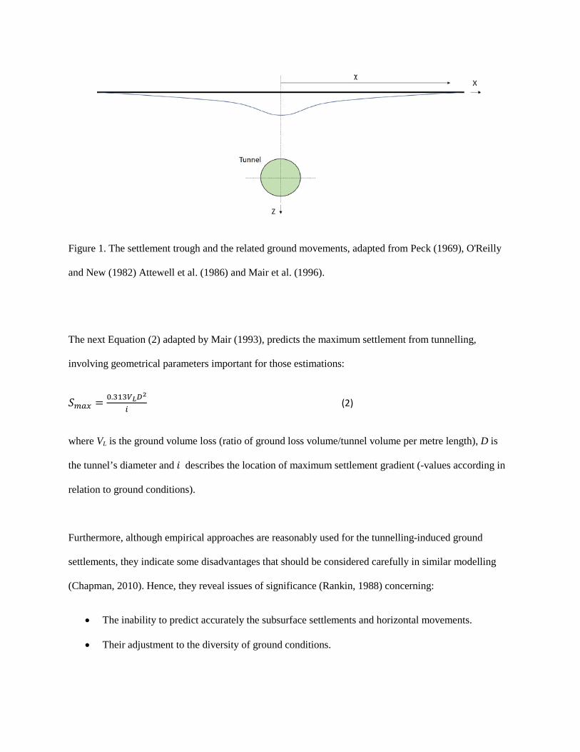
Figure 1. The settlement trough and the related ground movements, adapted from Peck (1969), O'Reilly
and New (1982) Attewell et al. (1986) and Mair et al. (1996).
The next Equation (2) adapted by Mair (1993), predicts the maximum settlement from tunnelling,
involving geometrical parameters important for those estimations:
𝑆𝑚𝑚𝑚 = 0.313𝑉𝐿𝐷2
𝑖 (2)
where VL is the ground volume loss (ratio of ground loss volume/tunnel volume per metre length), D is
the tunnel’s diameter and 𝑖 describes the location of maximum settlement gradient (-values according in
relation to ground conditions).
Furthermore, although empirical approaches are reasonably used for the tunnelling-induced ground
settlements, they indicate some disadvantages that should be considered carefully in similar modelling
(Chapman, 2010). Hence, they reveal issues of significance (Rankin, 1988) concerning:
• The inability to predict accurately the subsurface settlements and horizontal movements.
• Their adjustment to the diversity of ground conditions.
2.2. Analytical methods
The ground movements from tunnelling with respect to strains in a homogeneous, isotropic and
incompressible soil from surficial ground loss is analytically studied by Sagaseta (1987). Another
example of the small number of similar studies regarding the involved ground movement factors is
provided by Verruijt and Booker (1996), who pointed out the same approach for a homogeneous elastic
soil by utilizing the same method as Sagaseta (1987).
Verruijt and Booker (1996) also improved predictions by including Poisson’s ratio for the ground loss as
well as adding the impact from an oval-shaped deformation along the tunnel’s centreline. The related
closed-form settlement Equation (3) is provided (Verruijt and Booker, 1996), yielding the following
ground settlement estimations:
𝑈𝑧 = −𝜀𝑅2 �𝑧1𝑟12
+ 𝑧2𝑟22�+ 𝛿𝑅2 �𝑧1�𝑘𝑚
2−𝑧12�𝑟14
+ 𝑧2�𝑘𝑚2−𝑧22�𝑟24
�+
+ 2𝜀𝑅2
𝑚�(𝑚+1)𝑧2
𝑟22+ 𝑚𝑧�𝑚2−𝑧22�
𝑟24� − 2𝛿𝑅2ℎ(𝑚
2−𝑧22
𝑟24+ 𝑚
𝑚+12𝑧𝑧2�3𝑚2−𝑧22�
𝑟26 ) (3)
where e is the uniform radial ground loss; δ is the long term ground deformation due to the ovalization of
the tunnel lining; z1 = z-h; z2 = x+h; r12 = x2+z1
2; r22 = x2+z2
2; R is the tunnel radius; h is the depth; m =
1(1-2v); k = v/(1-v) and ν is the Poisson’s ratio of soil.
The previous equations were refined by Loganathan and Poulos (1998), who specified boundary
conditions accounting for the ground loss while tunnelling. The Equation (4) by Loganathan and Poulos
(1998), which models successfully the ground settlement from tunnelling excavations and leads to
efficient findings, is mentioned next.
Surface Settlement
𝑈𝑧=0 = 𝜀0𝑅24𝐻(1−𝜈)𝐻2+𝑚2
𝑒𝑒𝑒 �− 1.38𝑚2
(𝐻𝐻𝐻𝐻𝐻+𝑅2)2� (4)

where Uz=0 is the ground surface settlement, Uz is the subsurface settlement, Ux is the lateral soil
movement, R is the tunnel radius, z is the depth below ground surface, H is the depth of tunnel axis level,
ν is the Poisson’s ratio of soil, ε0 is the average ground loss ratio (not a displacement), x is the lateral
distance from tunnel centerline and β is the Limit angle of 45 + φ/2.
3. Methodology
The previous analytical Equations (3) and (4) have been merged with the BIM-based data of buildings to
generate a fully integrated and automated platform to analyze and visualize in three dimensions the
tunnelling-induced settlement damage prediction and distributions to the adjacent buildings. An overview
of the proposed methodology is presented in Figure 2.
Figure 2. Proposed methodology flow chart.

3.1. 3D BIM – IFC modelling
The proposed methodology employs the IFC (buildingSMART, 2017) data standards to enable the
desired building geometry and structural features and characteristics to be imported to (and exported
from) BIM. This is significant for this study as it can support the integration aspects, producing the initial
3D geo-visualisations and basic features needed for the building-settlement risk assessments.
SketchUp™ by Trimble Inc. (2016) is utilized in the proposed methodology as the 3D visualization
software, having an easy-to-use Graphical User Interface (GUI) while simultaneously enabling the user to
easily import BIM-IFC models and further modify them in 3D.
In this study, a 3D object-based model of a two-storey building is utilized that is freely available from
SUplugins (SUPodium, 2018), aligning with the BIM and IFC paradigms. The floor plan of the IFC
model was developed in Archicad (Graphisoft, 2018) and Figure 3 shows the model after it has been
imported in SketchUp (Trimble Inc., 2016).
The building consists of four structural-elements groups:
• 19 column objects.
• 10 beam objects.
• 22 wall objects.
• 14 slab objects.
To simulate a typical urban neighbourhood, the building was copied into ten similar buildings of different
sizes as shown in 3D in Figure 4.

Figure 3. Original 3D IFC building model in SketchUp.
Figure 4. 3D IFC building block model in SketchUp.
This IFC-model file containing the ten buildings has been assumed to be overlaid onto a satellite image of
the southwestern part of the campus of the University of Birmingham, UK as shown in Figure 5.
Figure 5. Ten IFC buildings superimposed onto the satellite image of the University of Birmingham, UK
campus.
3.2. STL-georeferenced building model
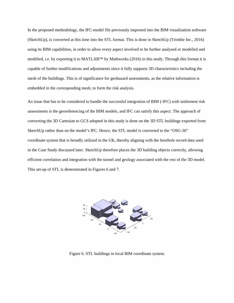
In the proposed methodology, the IFC-model file previously imported into the BIM visualisation software
(SketchUp), is converted at this time into the STL format. This is done in SketchUp (Trimble Inc., 2016)
using its BIM capabilities, in order to allow every aspect involved to be further analysed or modelled and
modified, i.e. by exporting it to MATLAB™ by Mathworks (2016) in this study. Through this format it is
capable of further modifications and adjustments since it fully supports 3D characteristics including the
mesh of the buildings. This is of significance for geohazard assessments, as the relative information is
embedded in the corresponding mesh, to form the risk analysis.
An issue that has to be considered to handle the successful integration of BIM (-IFC) with settlement risk
assessments is the georeferencing of the BIM models, and IFC can satisfy this aspect. The approach of
converting the 3D Cartesian to GCS adopted in this study is done on the 3D STL buildings exported from
SketchUp rather than on the model’s IFC. Hence, the STL model is converted to the “OSG-36”
coordinate system that is broadly utilized in the UK, thereby aligning with the borehole record data used
in the Case Study discussed later. SketchUp therefore places the 3D building objects correctly, allowing
efficient correlation and integration with the tunnel and geology associated with the rest of the 3D model.
This set-up of STL is demonstrated in Figures 6 and 7.
Figure 6. STL buildings in local BIM coordinate system.
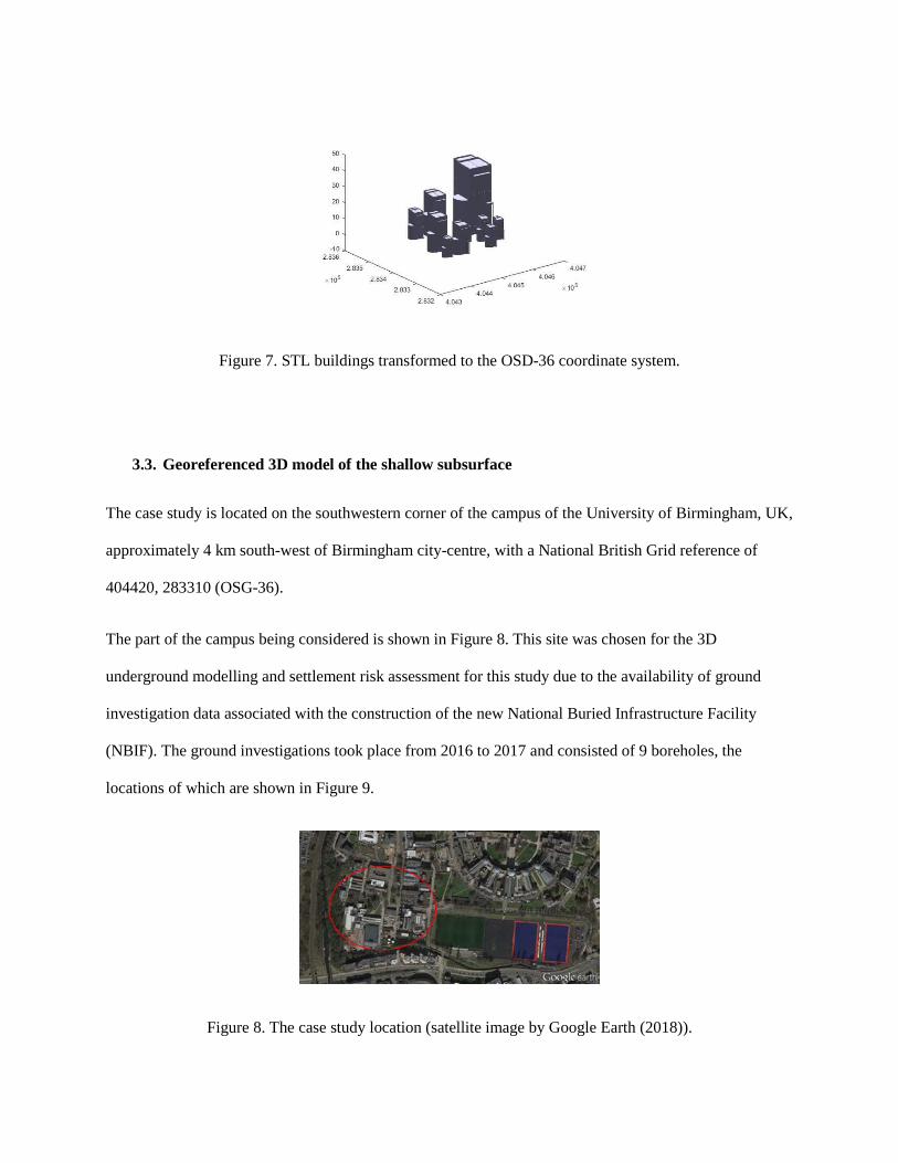
Figure 7. STL buildings transformed to the OSD-36 coordinate system.
3.3. Georeferenced 3D model of the shallow subsurface
The case study is located on the southwestern corner of the campus of the University of Birmingham, UK,
approximately 4 km south-west of Birmingham city-centre, with a National British Grid reference of
404420, 283310 (OSG-36).
The part of the campus being considered is shown in Figure 8. This site was chosen for the 3D
underground modelling and settlement risk assessment for this study due to the availability of ground
investigation data associated with the construction of the new National Buried Infrastructure Facility
(NBIF). The ground investigations took place from 2016 to 2017 and consisted of 9 boreholes, the
locations of which are shown in Figure 9.
Figure 8. The case study location (satellite image by Google Earth (2018)).
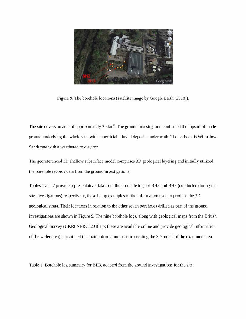
Figure 9. The borehole locations (satellite image by Google Earth (2018)).
The site covers an area of approximately 2.5km2. The ground investigation confirmed the topsoil of made
ground underlying the whole site, with superficial alluvial deposits underneath. The bedrock is Wilmslow
Sandstone with a weathered to clay top.
The georeferenced 3D shallow subsurface model comprises 3D geological layering and initially utilized
the borehole records data from the ground investigations.
Tables 1 and 2 provide representative data from the borehole logs of BH3 and BH2 (conducted during the
site investigations) respectively, these being examples of the information used to produce the 3D
geological strata. Their locations in relation to the other seven boreholes drilled as part of the ground
investigations are shown in Figure 9. The nine borehole logs, along with geological maps from the British
Geological Survey (UKRI NERC, 2018a,b; these are available online and provide geological information
of the wider area) constituted the main information used in creating the 3D model of the examined area.
Table 1: Borehole log summary for BH3, adapted from the ground investigations for the site.

Geological Stratum – BH3 Depth (m)
Made ground (gravel, red-brick gravel, cobbles with concrete) 0-5.0
Clay (stiff brown sandy) 5.0-6.0
Sandstone (very weak brown / sub-horizontal discontinuities,
with a 30mm band of brown sandy clay)
6.0-6.85
Clay (stiff brown locally grey gravelly slightly sandy) 6.85-7.6
Sandstone (very weak brown / horizontal to sub-horizontal
discontinuities, with thin mudstone bands)
7.6-20.5 (borehole
completed)
Table 2: Borehole log summary for BH2, adapted from the ground investigations for the site.
Geological stratum – BH2 Depth (m)
Made ground (brown sand, sandy gravel, red-brick gravel and
concrete)
0-3.3
Gravel (dense brown sandy clayey) 3.3-6.3
Clay (stiff brown) 6.3-6.5
Sandstone (very to extremely weak and thinly bedded /
horizontal discontinuities, with very thin mudstone bands)
6.5-20.5 (borehole
completed)
Triangulated interpolation is then conducted in MATLAB to create the geological layers within the 3D
model. This is achieved by modelling the top and bottom surfaces of each layer, utilising its thickness and

subsequently joining them together into a single layer or stratigraphic unit. The boundaries of the
geological layers can be adapted by using a standard triangulation algorithm in MATLAB, as it proved to
be both feasible and efficient for carrying out geological layering and modelling. In detail, the thickness
estimation of the topsoil is carried out by subtracting the available Digital Elevation Model (DEM) data
from the boundary depth of the first layer taken from the borehole records.
Due to the lack of open-access DEM data aligning with the study area, the elevation data was processed
from Google Earth (Google Inc, 2018) to form a DEM for the area. This was achieved by collecting the
elevation data for 200 points across the site from Google Earth Pro (Google Earth, 2018). This proved
sufficient for the present study, however other approaches should be considered for other engineering
studies depending on their focus and required DEM scales. In addition, to make sure that there were no
gaps or overlaps between the geological strata, the bottom surface was set to align with the top surface of
the layer beneath. The resulting 3D geology for the site is presented in the Figure 10 and with exploded
view in Figure 11.
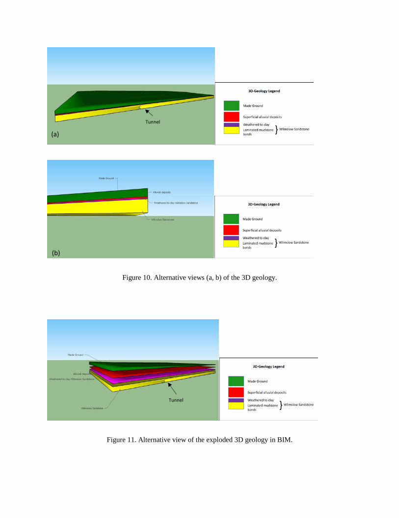
Figure 10. Alternative views (a, b) of the 3D geology.
Figure 11. Alternative view of the exploded 3D geology in BIM.
(a)
(b)
Tunnel
Tunnel

3.4. 3D georeferenced tunnel model
The next stage is to include the 3D tunnel model into the 3D geology model. This is produced by a
cylindrical surface triangulation. In this study, a cylindrical surface of a diameter of 12m was adopted at a
depth of approximately 20m (100mAOD) for the tunnel’s centerline. The proposed methodology utilizes
the differential Boolean operation function of MATLAB between the subsurface layer meshing and the
tunnel model meshing. Thus, the integrated 3D Ground-Building-Tunnel meshing model was produced
and is presented in the Figure 12.
Figure 12. 3D buildings-subsurface-tunnel objects views in BIM.
4. 3D Tunnelling-induced risk assessment results and discussion
As stated previously, there are a number of approaches adopted in the literature for the assessment of
building risk due to tunnelling, of which the methodology described below is one. However, it is the
principle of its use in a BIM type environment that is being demonstrated in this paper rather than
suggesting this is the only (or best) method to adopt. The assessment method involves two Phases:
4.1. Phase 1 Preliminary building damage assessment
Tunnel

Since any 3D building object in the site area is embedded in the integrated building-subsurface-tunnel
modelling process, the preliminary Phase 1 building damage assessment procedure as described earlier in
the methodology flow chart (Figure 2) was conducted. At this stage the building risk category was
estimated using the approach developed by Rankin (1988) and adapted from CIRIA (1996); this is
presented in Table 3. The damage classification of each building was produced after extraction of the
maximum settlement of the ground underneath each building footprint and the maximum slope (tilt). The
maximum slope of each building was estimated from the ratio of the differential settlement between the
predicted maximum and minimum settlement within each building footprint divided by the distance
between the meshing points of these settlements. This estimation was carried out in MATLAB.
Table 3. Damage classification – typical values, adapted from Rankin (1988), CIRIA (1996) and
Chapman (2010).
Risk
Category
1
2
3
4
Maximum
slope of
building
< 1/500
1/500 to
1/200
1/200 to 1/50
> 1/50
Maximum
settlement of
building (mm)
< 10
10 to 50
50 to 75
> 75
Risk description
Negligible: superficial damage unlikely
Slight: possible superficial damage that is unlikely to
have structural significance
Moderate: expected superficial damage and possible
structural damage to building, possible damage to
relatively rigid pipelines
High: expected structural damage to buildings and
rigid pipelines or possible damage to other pipelines

To extract the maximum and minimum settlement falling inside the building footprint, the ground
settlement as well as the horizontal movement was derived in 3D by employing Equation (4) in
MATLAB and producing settlement susceptibility maps using SketchUp software. From this ground
displacement information, two risk based colour maps were produced; one for the ground surface
settlement, which extends across the ground surface, and one for the slope of the buildings, which is
presented by colours on the faces of each of the investigated buildings.
To demonstrate the proposed methodology, three different locations of the tunnel centreline have been
considered: 30m and 10m offset from the first building and beneath the building block. Figures 13-15
present in 3D the impact of tunnelling on the adjacent buildings as the distance to them decreases. It is
evident that the proposed 3D visualization approach enhances the multidimensional assessment
depictions, thereby providing a better understanding of the risks associated with the different tunnelling
options.
(a)
(b)
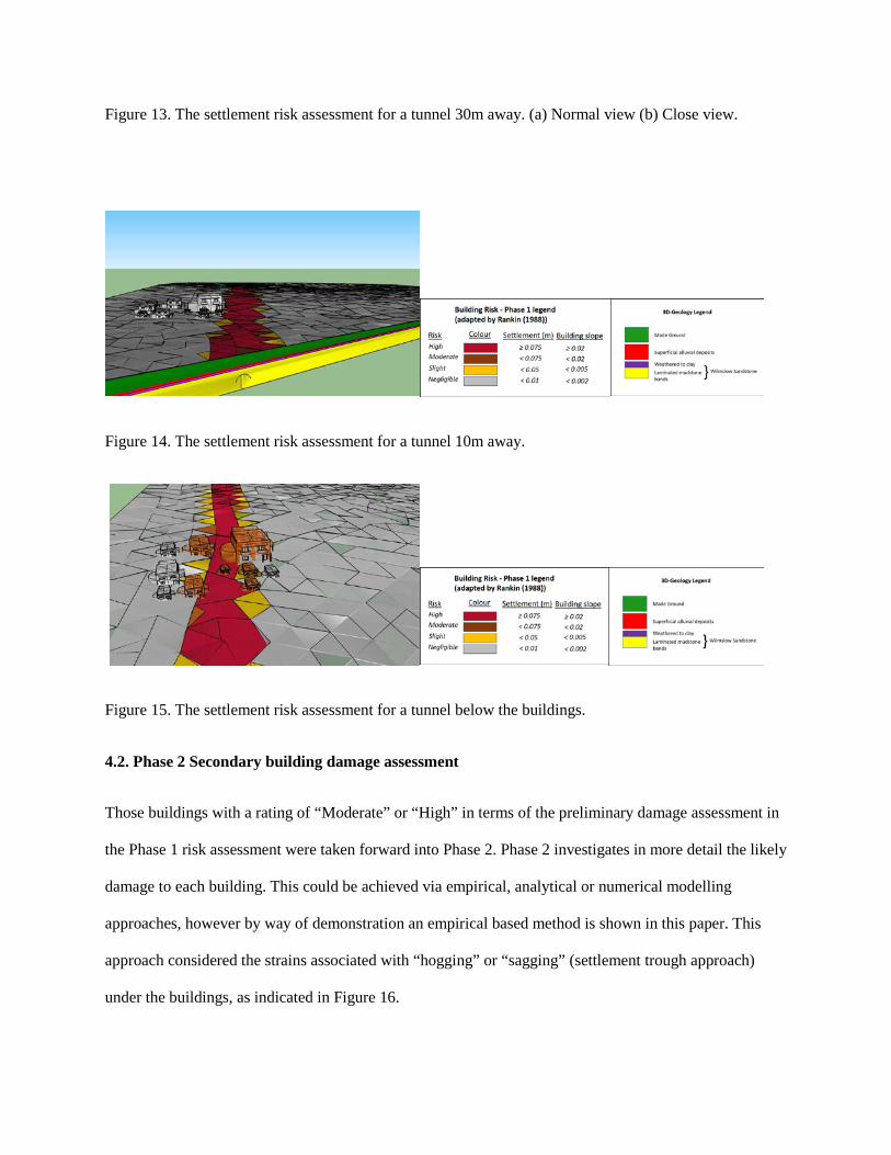
Figure 13. The settlement risk assessment for a tunnel 30m away. (a) Normal view (b) Close view.
Figure 14. The settlement risk assessment for a tunnel 10m away.
Figure 15. The settlement risk assessment for a tunnel below the buildings.
4.2. Phase 2 Secondary building damage assessment
Those buildings with a rating of “Moderate” or “High” in terms of the preliminary damage assessment in
the Phase 1 risk assessment were taken forward into Phase 2. Phase 2 investigates in more detail the likely
damage to each building. This could be achieved via empirical, analytical or numerical modelling
approaches, however by way of demonstration an empirical based method is shown in this paper. This
approach considered the strains associated with “hogging” or “sagging” (settlement trough approach)
under the buildings, as indicated in Figure 16.

Equations (5) to (7) show the bending (Σb), diagonal (Σd) and horizontal (Σh) strain (Burland and Wroth,
1974):
𝛥𝐵
= ( 𝐿12𝐻
+ 3𝐼𝐼2𝐻𝐿𝐻𝑡
)𝜀𝑏 (5)
𝛥𝐵
= (𝐻𝐿2𝑡
18𝐼𝐼+ 1)𝜀𝑑 (6)
𝜀ℎ = 𝛥ℎ𝛣𝑑
(7)
where H = Building height; E/G = Relationship between Young’s modulus and shear modulus of the
building; L = Length of the considered building span; I = Section moment of area of the equivalent beam
height of the building at the respective zone (sagging zone: I=H3/12 and hogging zone: I=H3/3); t =
Furthest distance from the neutral axis to the edge of the equivalent beam (sagging zone: t=H/2, hogging
zone: t=H); Δ = Maximum relative settlement (deflection) at the considered span; Δ/L = Ratio between
the maximum relative settlement at the considered span and the length of this span (deflection ratio); B =
Building width.
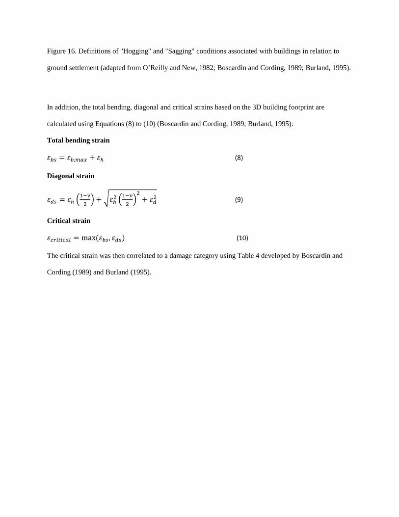
Figure 16. Definitions of "Hogging" and "Sagging" conditions associated with buildings in relation to
ground settlement (adapted from O’Reilly and New, 1982; Boscardin and Cording, 1989; Burland, 1995).
In addition, the total bending, diagonal and critical strains based on the 3D building footprint are
calculated using Equations (8) to (10) (Boscardin and Cording, 1989; Burland, 1995):
Total bending strain
𝜀𝑏𝑏 = 𝜀𝑏,𝑚𝑚𝑚 + 𝜀ℎ (8)
Diagonal strain
𝜀𝑑𝑏 = 𝜀ℎ �1−𝜈2�+ �𝜀ℎ2 �
1−𝜈2�2
+ 𝜀𝑑2 (9)
Critical strain
𝜀𝐻𝑟𝑖𝐻𝑖𝐻𝑚𝑐 = max (𝜀𝑏𝑏, 𝜀𝑑𝑏) (10)
The critical strain was then correlated to a damage category using Table 4 developed by Boscardin and
Cording (1989) and Burland (1995).
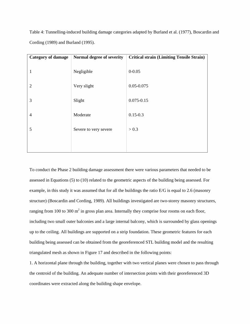
Table 4: Tunnelling-induced building damage categories adapted by Burland et al. (1977), Boscardin and
Cording (1989) and Burland (1995).
Category of damage
1
2
3
4
5
Normal degree of severity
Negligible
Very slight
Slight
Moderate
Severe to very severe
Critical strain (Limiting Tensile Strain)
0-0.05
0.05-0.075
0.075-0.15
0.15-0.3
> 0.3
To conduct the Phase 2 building damage assessment there were various parameters that needed to be
assessed in Equations (5) to (10) related to the geometric aspects of the building being assessed. For
example, in this study it was assumed that for all the buildings the ratio E/G is equal to 2.6 (masonry
structure) (Boscardin and Cording, 1989). All buildings investigated are two-storey masonry structures,
ranging from 100 to 300 m2 in gross plan area. Internally they comprise four rooms on each floor,
including two small outer balconies and a large internal balcony, which is surrounded by glass openings
up to the ceiling. All buildings are supported on a strip foundation. These geometric features for each
building being assessed can be obtained from the georeferenced STL building model and the resulting
triangulated mesh as shown in Figure 17 and described in the following points:
1. A horizontal plane through the building, together with two vertical planes were chosen to pass through
the centroid of the building. An adequate number of intersection points with their georeferenced 3D
coordinates were extracted along the building shape envelope.

2. The maximum distances in relation to the horizontal section plane provided both the width and the
length of each building being assessed, while the maximum distance in the vertical plane provided the
height of each building.
Figure 17. The triangulated mesh approach used in this study, and how the various building parameters
were estimated for the Phase 2 risk assessment. Orange: Horizontal plane. Cyan and Green: Vertical
planes.
After the evaluation of critical strain from Equation (10) for each building, a colourmap can be adopted
for the background colour of the building faces. In addition, the settlement curve below every assessed
building in that direction can also be visualized below each building.
The map of buildings used in the current study is shown in Figure 18. Figures 19-22 present examples of
the Phase 2 risk assessment, with the settlement trough demonstrated as the blue curve below the
buildings in comparison with the horizontal level (green line). For the same figures, the buildings used
were selected in order to provide a thorough view of the assessment by indicating different risk. The rest

of the coloured dots in the demonstrations show the section planes. More specifically, the blue, red and
pink/purple dots define the outer shape of each investigated building, and they are represented by planes
passing through the centroid of the building, being parallel to the length (vertical plane of Figure 17 in
green), the width (vertical plane of Figure 17 in cyan) and the footprint plan area (horizontal plane of
Figure 17 in orange) of the building, respectively.
Figure 18. The map of the building footprints and the tunnel’s centreline.

Figure 19. Phase 2 assessment and damage risk level for the Building 2, (a) along the longest dimension
and (b) along the vertical dimension.
(b)
(a)
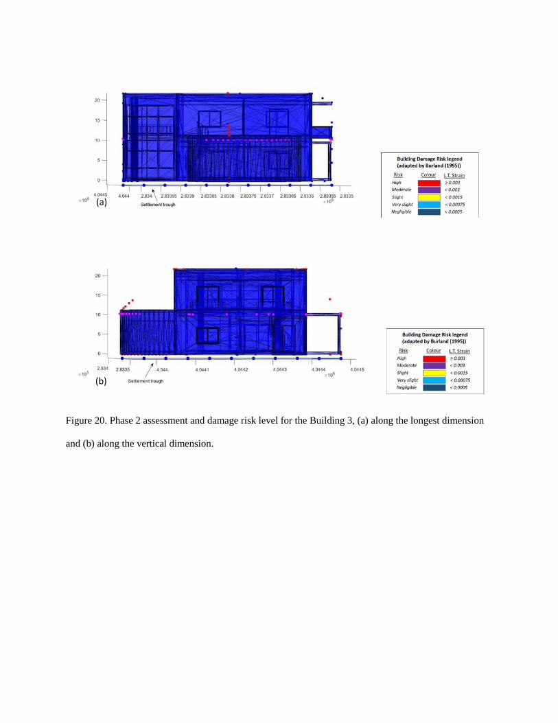
Figure 20. Phase 2 assessment and damage risk level for the Building 3, (a) along the longest dimension
and (b) along the vertical dimension.
(b)
(a)

Figure 21. Phase 2 assessment and damage risk level for the Building 4, (a) along the longest dimension
and (b) along the vertical dimension.
(a)
(b)

Figure 22. Phase 2 assessment and damage risk level for the Building 9, (a) along the longest dimension
and (b) along the vertical dimension.
As demonstrated in the previous analysis, the methods proposed in this paper can provide a unique way of
integrating both the building-related BIM models with the geological information in a dynamic way that
allows users to assess the effects of new construction activities on existing infrastructures. In the case of
this paper, this has involved a new tunnel construction affecting existing buildings. The ability to
integrate calculations (this can be via empirical, analytical or numerical modelling methods) and
visualisations within a dynamic BIM environment is a unique feature of the presented modelling
(a)
(b)

approach. Although this has been demonstrated using a relatively simple example, it can be extended to
provide a powerful tool for decision makers.
5. Conclusions
This paper has presented an integrated 3D BIM-geology interaction methodology that can include the
effects of new infrastructure construction on the surrounding environment. This methodology has made
use of a combination of MATLAB tools, the 3D visualization capabilities of the Sketchup design
software and the conversion procedures from BIM to IFC to STL models and vice versa.
The example used in this paper to demonstrate the proposed approach has involved a new tunnel
construction and the associated damage assessment for the buildings in the vicinity of this construction.
This approach begins with the extraction of basic engineering parameters (e.g. building geometries)
adopted in the BIM framework to generate the corresponding settlement input data to the integrated
model.
It has been also shown from the outcomes of the proposed methodology that, while there has been a
growing interest in the other domains of the AEC industry for the use of the IFC, there is certainly
potential in geotechnics.
The access to detailed interaction information and powerful visualisations could provide a powerful
decision-making tool that is able to assess a number of different options in the same modelling
environment. In the case demonstrated in this paper, i.e. the effects of a new tunnel on existing buildings,
it can assist route decisions and the effects of these decisions in terms of building risk assessment. The
proposed framework taking into account the interactions between the 3D BIM structural models and the
associated geological interactions, although posing a number of challenges, also has the potential to be
extended to city or regional scales, due to the efficient nature of the proposed approach.

Acknowledgements
The authors gratefully acknowledge the financial support of the UK Engineering and Physical Sciences
Research Council (EPSRC) under grant number EP/N010523/1 (Balancing the impact of City
Infrastructure Engineering on Natural Systems using Robots), to which this PhD project was linked, and
the first author gratefully acknowledges the financial support of the University of Birmingham.
References
3D systems, 2018. STL File (website: https://uk.3dsystems.com/) [Accessed 5 March 2018].
Attewell, P.B. and Woodman, J.P., 1982. Predicting the dynamics of ground settlement and its deriving
caused by tunnelling in soil. Ground Engineering 15 (7), PP.13–22.
Attewell, P.B, Yeats, J, and Selby, A.R, 1986. Soil Movements Induced by Tunneling and Their Effects
on Pipelines and Structures. Glasgow: Blackie.
Autodesk Inc., 2018. Revit (website: https://www.autodesk.co.uk) [Accessed 10 March 2018]
Borrmann, A., Kolbe, T., Donaubauer, A., Steuer, H., Jubierre, J. and Flurl, M., 2014. Multi-Scale
Geometric-Semantic Modeling of Shield Tunnels for GIS and BIM Applications. Computer-Aided Civil
and Infrastructure Engineering, 30 (4), pp.263-281.
Boscardin, M. D. and Cording, E. J., 1989. Building response to excavation–induced settlement. Journal
of Geotechnical Engineering 115(1), 1–21.
buildingSMART, 2017. Industry Foundation Classes Edition 3 (website: http://www.buildingsmart.org)
[Accesed 20 March 2017].
Burland, J. B., 1995. Assessment of risk of damage to buildings due to tunnelling and excavation. Invited
Special Lecture. In: 1st Int. Conf. on Earthquake Geotech. Engineering, IS Tokyo '95.
Burland, J. B. and Wroth, C. P., 1974. Settlement of buildings and associated damage. In Settlement of
structures, pp. 611–654. London: Pentech Pr.
Burland, J. B., Standing, J. R., Jardine, F. M., 2001. Building response to tunnelling - Case studies from
construction of the Jubilee Line Extension, Volume 1: Projects and Methods. London: T. Telford.
Burland, J.B., Broms, J.B. and de Mello, V.F.B., 1977. Behavior of foundations and structures on soft
ground. Proceedings of the 9th International Conference on Soil Mechanics and Foundation Engineering
(SMFE), Tokyo, Japan, July 10- 15, 1977, pp.495-546.
Chapman, D.N., 2010. Introduction to tunnel construction / David N. Chapman, Nicole, and Alfred Stärk.
Taylor & Francis, New York.
Chiu, W.K. and Tan, S.T., 2000. Multiple material objects: from CAD representation to data format for
rapid prototyping. Computer-aided design, 32(12), pp.707-717.
CIRIA, 1996. Prediction and effects of ground movements caused by tunnelling in soft ground beneath
urban areas. Construction Industry Research and Information Association (CIRIA). Project Report 30.
Cording, E.J. and Hansmire, W.H., 1975. Displacements around soft ground tunnels. Proceedings of the
5th Pan-American Conference on Soil Mechanics and Foundation Engineering, Buenos Aires, Argentina,
October 27-31, 1975, pp.571-633.
Eastman, C., Teicholz, P., Sacks, R. and Liston, K., 2011. BIM Handbook (2nd Edition) A Guide to
Building Information Modeling for Owners, Managers, Designers, Engineers and Contractors, John
Wiley & Sons, New Jersey
Google Earth, 2018. Birmingham, UK; (from website: http://www.google.com/earth/index.html) [Viewed
15 March 2018].
Google Earth, 2018. Birmingham, UK; (from website: http://www.google.com/earth/index.html) [Viewed
18 March 2018].
Google Inc., 2015. Google Earth Pro (website: https://earth.google.com/download-earth.html) [Accessed
15 June 2017].
Graphisoft Inc., 2018. Archicad 22 (http://www.graphisoft.com/archicad/) [Accessed 15 January 2018].
Hunt, D., Makana, L., Jefferson, I. and Rogers, C.D.F., 2016. Liveable cities and urban underground
space. Tunnelling and Underground Space Technology, 55, pp.8-20.
Imseeh, W.H. and Alshibli, K.A., 2018. 3D finite element modelling of force transmission and particle
fracture of sand. Computers and Geotechnics Volume 94, Pages 184-195.
Kessler, H., Wood, B., Morin, G., Gakis, A., McArdle, G., Rabson, O., Fitzgerald, R. and Dearden, R.,
2015. Building Information Modelling (BIM) – A Route for Geological Models to Have Real World
Impact. Special Report. AER/AGS, pp.13-18.
Kim, S., Kim, J., Jung, J. and Heo, J., 2015. Development of a 3D Underground Cadastral System with
Indoor Mapping for As-Built BIM: The Case Study of Gangnam Subway Station in Korea. Sensors,
15(12), pp.30870-30893.
Loganathan, N. and Poulos, H., 1998. Analytical Prediction for Tunneling-Induced Ground Movements in
Clays. Journal of Geotechnical and Geoenvironmental Engineering, 124(9), pp.846-856.
Mair, R. J., 1993. The unwin memorial lecture 1992: Developments in geotechnical engineering research:
application to tunnels and deep excavations. Proc. Instn. Civ. Engrs. Civil Engineering, 97, pp. 27-41.
Mair, R. J., Taylor, R. N. and Burland, J. B., 1996. Prediction of ground movements and assesment of
risk of building damage due to bored tunnelling. In Geotechnical aspects of underground construction in
soft ground, pp. 713–718. Rotterdam: Balkema.
Mathworks Inc., 2016. Matlab R2016a (https://uk.mathworks.com/products/matlab.html) [Accessed 12
December 2016].
O’Reilly, M.P. and New, B.M., 1982. Settlements above tunnels in the United Kingdom – their
magnitude and prediction. Tunnelling’82. The Institution of Mining and Metallurgy, London, pp. 55–64.
Peck, R.B., 1969. Deep excavations and tunnelling in soft ground. In: Proceedings of the 7th
International Conference on Soil Mechanics and Foundation Engineering, State of the Art Volume, vol. 3.
Mexican Society of Soil Mechanics, Mexico, pp. 225–290.
Price, S., Ford, J., Campbell, S. and Jefferson, I., 2016. Urban Futures: the sustainable management of the
ground beneath cities. Geological Society, London, Engineering Geology Special Publications, 27(1),
pp.19-33.
Qu, X., and Stucker, B., 2003. A 3D surface offset method for STL‐format models, Rapid Prototyping
Journal, Vol. 9 Issue: 3, pp.133-141.
Rankin, W., 1988. Ground movements resulting from urban tunnelling: predictions and
effects. Geological Society, London, Engineering Geology Special Publications, 5(1), pp.79-92.
Rogers, C.D.F., 2009. Substructures, underground space and sustainable urban environments. Geol. Soc.,
London, Eng. Geol. Spec. Publ. 22 (1), 177–188.
Sagaseta, C., 1987. Analysis of undrained soil deformation due to ground loss. Geotechnique, London,
England, 37, 301-320.
Schindler, S., Hegemann, F., Koch, C., König, M. and Mark, P., 2016. Radar interferometry based
settlement monitoring in tunnelling: Visualisation and accuracy analyses. Visualization in Engineering
pp.4-7.
Silva, M., Salvado, F., Couto, P. and Azevedo, Á., 201. Roadmap Proposal for Implementing Building
Information Modelling (BIM) in Portugal. OJCE, 06(03), pp.475-481.
Steel, J., Drogemuller, R. and Toth, B., 2012. Model interoperability in building information modelling.
Softw Syst Model (11) pp. 99–109.
SUPodium, 2018. SUPlugins (from website: http://www.SUplugins.com/ifc2skp.php) [viewed on 3 June
2018].
Tawelian, L. and Mickovski, S., 2016. The Implementation of Geotechnical Data into the BIM Process.
Procedia Engineering, 143, pp.734-741.
Trimble Inc., 2016. Sketchup Pro 2016. (https://www.sketchup.com/) [Accessed 3 November 2016]
UKRI NERC, 2018a. BGS Geoindex. From website: https://www.bgs.ac.uk/geoindex/ [Accessed
10.06.2018].
UKRI NERC, 2018b. BGS Geology of Britain viewer. From website:
https://www.bgs.ac.uk/discoveringGeology/geologyOfBritain/viewer.html [Accessed 10.06.2018].
Verruijt, A., and Booker, J. R., 1996. Surface settlements due to deformation of a tunnel in an elastic half
plane." Geotechnique, London, England, 46(4), 753-756.