Embed Size (px)
Citation preview
A9 A 5 ~ E 8 UNITED STATES
DEPARTdENT OF THC INrERlOR FILE COPY
BUREAU OF RECLAMAT1 ON BUREAU OF R E C L A M A T I O N HYDRALJLI C LhaCR A'I'ORY
NOT TO BE REUOVED FROM FI -
FLOW CHARACTERISTICS
OF AN
IRVINE 4-1NCI-I BALANCED REGULATOR
Hydraulic Laboratory Report No Hyd. 260
RE,SEARCH AND GEOLOGY DIVISION
*W lo b e reproduced or distrtbured outride the Burcau of h.eclamrtion
BRANCH OF DESIGN AND CONSTRUCTION
DEN'.IER. CQLORADO
MARCH 31,1949

Branch of Design and Construction Labortitory Repart No. ' Hyd 260 Research and Geology Division Hydraulic Laboratory Denver, Colorado Campiled by: W. C. Case h k c h 31, 1949 Revieweb by: J. W. Ball and
C. W e v l ! h ~ e
Subject: Flow character is t ics of an b v i n e 4-inch Balanced Regulator.
PURPOSE
1. To determlr?e the flow chersr;tsris€ics of a 4-inch Irvine Balanced Regulator.
2. To appraise the mechanical durabi l i ty of this water-control device.
CONCLUSIONS
1. Campared t o a &-inch giobe valve, the capacity of the 4-inch regulator i s greeter and the head loas i s l e s s ( ~ i g u r e 9).
2. The 4-inch regulator has considerably l e s s capacity than a k-Inch gate valve and the head losa is much gresker (Figure 9).
3. The regulator will not function as a qhutoff device eince the re i s leakage when the v d v e s axe in 'the closed pos2tion.
4. For a given f loa t setting, variable in le t preseure tmd/or variable discharge from the intake box, the regulator w i l l maintain a head in the intake box only within the l M t s of the f l o a t travel, 9-3/4 inches or the f low capacity of the kegulatar.
5. The regulator valves w i l l not hunt appreciably when c o ~ i t i o n e are set for constant flow and constant i n l e t presswe, as evidanced by t h e maximum ver t ica l f loa t movement of 3/8 inch observed in the tes ta made on t h i s regulator,
a. Other factors remainlag the same, t h i s ver t ica l flaat movament wil l increase if the regulator elze (flow) is increseed, and/or the depth of water over the regulator i s decreasad. Eccese- ive f l o a t movement w i l l probably shurten the l ife of the re@ihtor.
b. To minimize wear of the regulator parts, a marimMl water surface area and maximum w a t e r depth over the regulator should be
6. Mechanically, the regulator i s unsatisfactory in the f o l l o w l ~ respects:
a. IT the setscrew holding the f loa t t o the rod should loosen, the regulator w i l l go t o the full open position and floodir@ w'; resu l t . A positive connection between f loa t and rod ahould be provided.
b. The hollow sheet-metal f loa t i s l ike ly t o leak, f i l l with water, or collapse when submerged. Flooding may resul t . A Wn- siakable-type f l o a t ahauld be provided.
Description of the Irvine Balanced Regulator
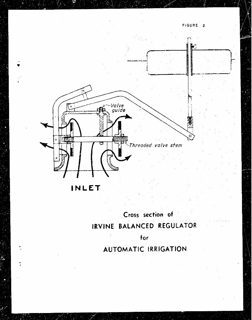
The &vine Balanced Regulator i s manufactured by the *vine Balanced Regulator Compfmy, 2729 North &oadw8y, L0s Angeles 31, California. This regulatar is designed t o give autamatic r e & a t i o n f o r land irrigation. The common ins ta l la t ion i s where the regulator controls the flow into an intake box which baa 8 number of lateral deliveriee. A general photographic view of the remdator 1 6 ahown in Flgure 1. A sectional view sketch i s shown i n Figure 2. A sketch of a typical in le t box ins ta l la t ion is shown i n Figure 3.
The foPlowf.lg features of the regulatm ere given by the manufacturer:
a. The &vine Balanced Regulator 18 balanced without the use of s p r l x s ,
b. Tha regulator i s of rugged bronze constr~ct ion.
c. The regulator i s not affected 'by the uae of st&?derd commercial f e r t i l i ze r s .
d. The design i s such tha t the regulator is easi ly adsptable t o concrete pipe, s t e e l pipe, and t rans i te pipe.
e. The operatioc of the regulator is independent of l n l e t pressure because it is~balanced. (HOW it i s balanced i s described 8ubsequentl;yr.) Regulators are i n everyday use xi th from 1 foot of water t o 150 ps i in le t pressure.
f . The capacity of the regulatoz6 18 equal t o tha t of any standard gate valve of the same diameter under the same head loss. h he manufacturer appears t o be $n errox irnd means standard "globe" instead of "ga2e" valve, a s shown by the head loss curves i n B m e 9. )
l a t e r a l s regardless of i n l e t pressure variations. h his "constant" head wi31 vary over the ver t ica l f l o a t t r ave l of 9-3/!4 inohee for the 4-inch regulator as the in le t pressure i s varied, and within the flow capacity of the regulator.)
h. The regulator saves water by the elimiaation of flooding, and thereby reduces erosion. (!Phis statement i s not fully correct as explained subsequently. )
I. After 3 years of w e no trouble has been experienced by algae a t t ach iw t o the regulators.
j. The regulator permits variable set t ings of the f l o a t t o meet different head requbements on the la tera ls . When once set , generally requires no further attention.
k. A .stock of 4-, 6 - , and 8-inch size8 l a carried. LBsger sizes can be made upon oraer. The approximate prices In 1947 were as follows:
6- inch 43
There i s an additional charge of $5 per valve fo r s t e e l pipe connections. The manufacturer claima there are approximately 1,500 regulators i n use on CaUfornia ranches.
Ref erring t o Item h above, flooding i e not bpoesible. The f l o a t i s attached t o the f loa t rod by means of a s i w e se t screw with no jam nu% or other locking device. 23' this setscr.ew becomes loose, the f l o a t w i l l no longer control the regulator valves which hll go t o the f u l l open position. Flooding may resul t . The f l o a t rod ahould have a number of through holes for vmious head settin@, and a bol t or tapered pin used t o se t the f loa t t o the rod, thus giving a more posl- t i v e connection.
On the regulator tested the thread lerrgth on the valve , stan fur attachlng the outside valve was ,boo long ( ~ i g u r e 2). The sharp eQes of the thread scraped on the imlde of the valve stem w i d e and might cause sticking or rough action of the valve e t a .
The linkege end of the valve stam b a v e l e is an a rc of a c i rc le (Figure 2). This causes poor sealing of the valves because they do not seat squarely. To provide the beat valve seating the valve st- should be perpendicular t o the valve lever when the vdvee are clomed. The design of the regulator makes t h i s set t ing impTactical eime the maximum valve opening would be greatly decreaeed; however, this eett iDg c o d a be obtained by a l te r ing the linkage. The valve wide-open stop i s where the linkage arm, attached t o the valve eteun, con ti act^ the value body. The v d v e face consists of a rubber-type ring bond* to the valve head t o a i b seall,n&
As discussed i n the - Test Results -- section of t h i s report, the forces on the two regulator valves are considerably unbalanced. In the wri ter 's opinion, the word "bd-anced" i n the name ,&vine Balanced Regulator connotes tha t the buoyant force of the f loa t balances out the unbalanced force created by the water pressure-momentum forces on the two valves. However, the forces on the two valves are par t ia l ly balanced. The two second-class levers incorporated into the regulator
d linkage provide a variable mechanical advantage from 2.6 t o 19.4, depend- ing on the position of the f l o a t ( ~ i g u r e 4). The dwensions of the cylindrical, hollow, sheet metal f l o a t are 7.89 inches i n diameter and 6.07 inches high. Therefore, when the f loa t i s completely submerged, it provides a maximum buoyant force of 10.74 pounds. This maxlmum b~oyan t force multiplied by the mechanical. a d v a n t ~ e a t various f l o a t (valve) positions gives the maximum force tha t the f loa t can provide t o the valve stem.
Test Procedure
A schematic d i w a m of the t e s t setup i s shown i n Figure 5. A general view of the intake box used i n t h i s study i s ahown i n Figme 6. Figure 1 shows a closeup view of the regulator instal led on %he 12-inch i n l e t pipe. The relationship between valve openiag and f loa t t ravel is shown on Figure 7. Curves of flow versus head loss across the regulator were obtained for six different openings of the regulator valve; namely, 20-, 40-, 60-, 80-, 90-, and 100-percent f l o a t t ravel from the closed valve position. For each curve, the f loa t rod was locked i n one of the a3ove-mentioned positions of f loa t travel. The water flow was measured by a caliBrated 6-inch venturi meter. The head loss upstream tap was placed about 2 f e e t from the regulator in the 12-inch pipe (Figure 6) and therefore, the head loss includes the 12-inch t o 4-inch 90° turn loss.
Test Results
The regulator capacity curves of flow ( ~ 2 ) versus head loss (ps-l) across the r e g u l a t ~ r at six different f loa t t r ave l positions (different valve openings) are shown i n Figure 8. The head loss with the 4-inch regulator valves f u l l open i s compared i n Figure 9 with those of a f u l l open &-inch glc,e valve and a full open 4-inch gate valve. The regulator has a larger &ischarge area than a globe valve, thus the lower head loss across the regulatm was as expected.
. Figure 10 shows the operating characteristics of the regulator *en . It is regulating near 1-second-foot flow. The curves on t h i s figure i l l u s t r a t e the magnitude of unbalanced force i n the regulator valves, and tha t the f loa t supplies the balancing force. The amount the regula- t o r valves are unbalanced i s found by mdtlplying the f loa t buoyant force
J
( l e s s the linkage weight) times tihe mechanical edvmtage of the linkage. As shown on the figure the f l o a t is of sufficient oize. For example, if the valve stem in same w a y bacame stcck st the 6-inch f l o a t t r ave l posttion, the f loa t can supply a maximum force of 200 pounds (top cmve) t o loosen the valve stem.
i n operation a t 1-second-foot flow. A t any flow within the l&ts of these t e s t s the maximum and minimum ver t ica l movement of the f l o a t and rod was 3/8 and 1/8 inch respectively, with an average movement near 1/4 inch. This ver t ica l movement of the f loa t i s caused by the turbul-
t ence of the water surface and hunting of the regulator valves. The f l o a t movement should be kept t o a minimum t o al leviate we= of the
0 moving parts.
An attempt was made t o use the regulator as a shutoff valve a t about 20 p s i i n l e t pressure. The regulator valves would not sea l with maximum f loa t buoyant force, and when a i r bubbles s tar ted t o appear at the soldered seams of the sheet-metal f loa t (the f l o a t top was submerged about 6 inches), the t e s t w a s discontinued. Thus, i n a f i e l d in8taJJ.a- tion, if all intake box outlets are closed, it Xs l ike ly tha t the regula- tor w i l l not function as a shutoff valve and flooding w i l l resul t . When the f loa t becomes submerged, it may leak, f i l l with water, or collapse. If the f loa t becomes f i l l e d w i t h water, the regulator valvea w i l l go to the full open position. Flooding around the inkake box area ney resul t . Therefore, a noruinkable-t,qe f loa t should be used.
Two possible locations fo r cavitation are indicated ( ~ i g u r e llb); i.e., at the outside valve seat and at the linkage attachment t o the valve stem which i s i n the flow path from the inside valve. Other points of cavitation may possibly be inside the regulator housing, In general, however, regulator in le t pressures i n the f i e l d wi l l be lower than the pressures used t o obtain Figures 9 and 10. Therefore, l i t t l e or no damaging cavitation is l ike ly t o occur.
A t cer tain p m t i a l valve openings a noise tha t restmibled linkage chatter due t o valve hunting was heard; but t h i s noise could have been due t o the high-velocity water flow from the submerged regulator valves into the intake box.
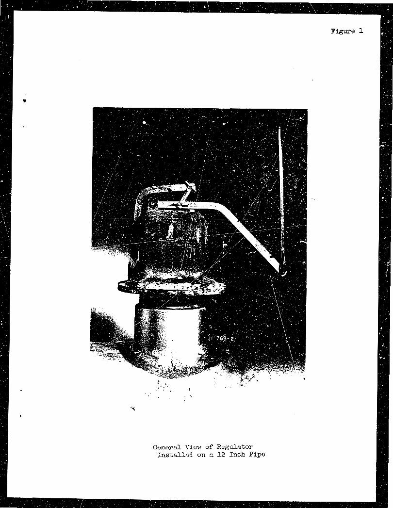
Gcrlcrd View of Regulator Iristill.fjd. or, a 12 Inch Pipe
Figure 1
I N L E T
Cross section of
lRVlNE BALANCED REGULATOR
tor
AUTOMATIC IRRIGATION
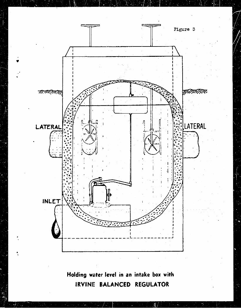
Holding water level in an intake box with
IRVINI:' BALAANCED REGULATOR

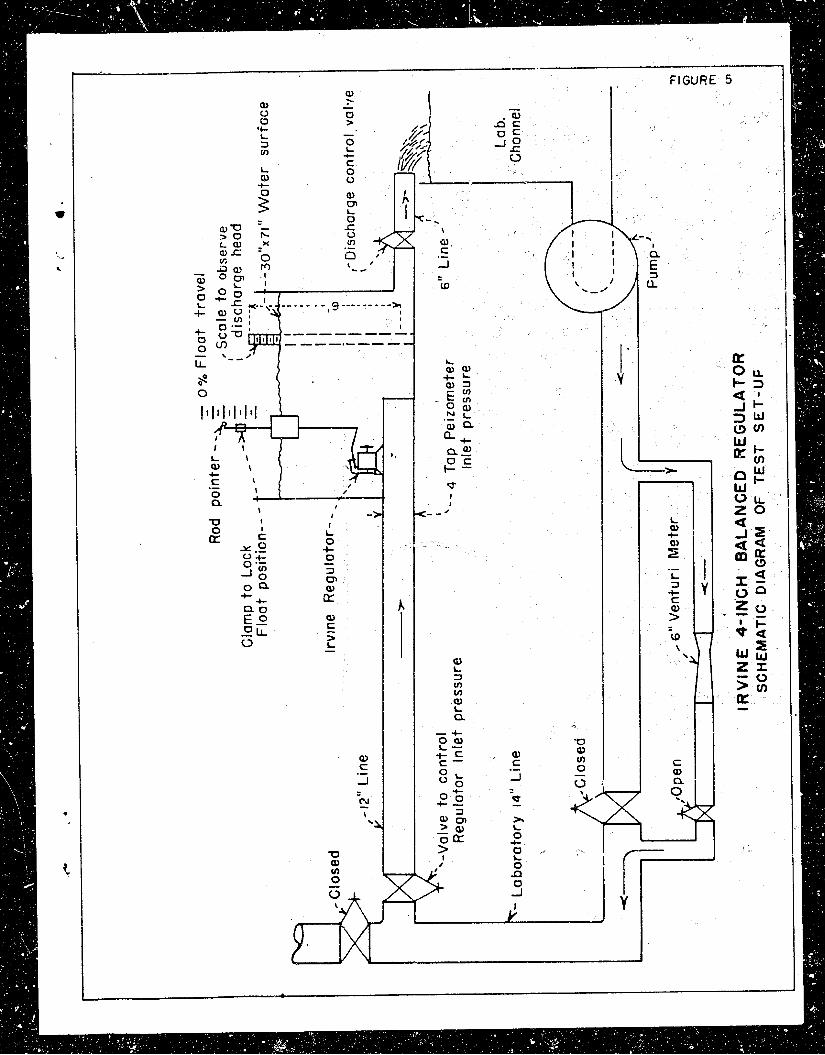

Figure 6
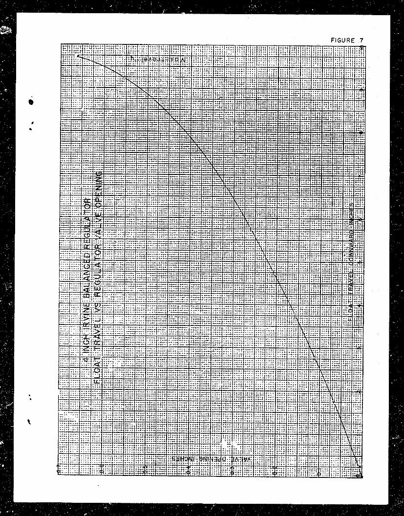
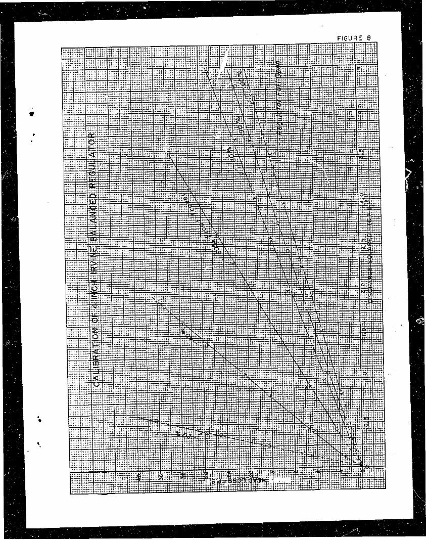
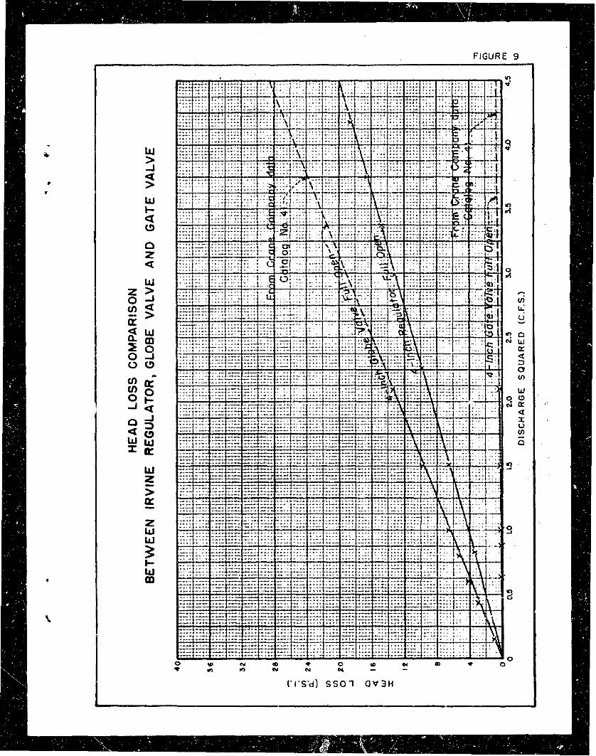
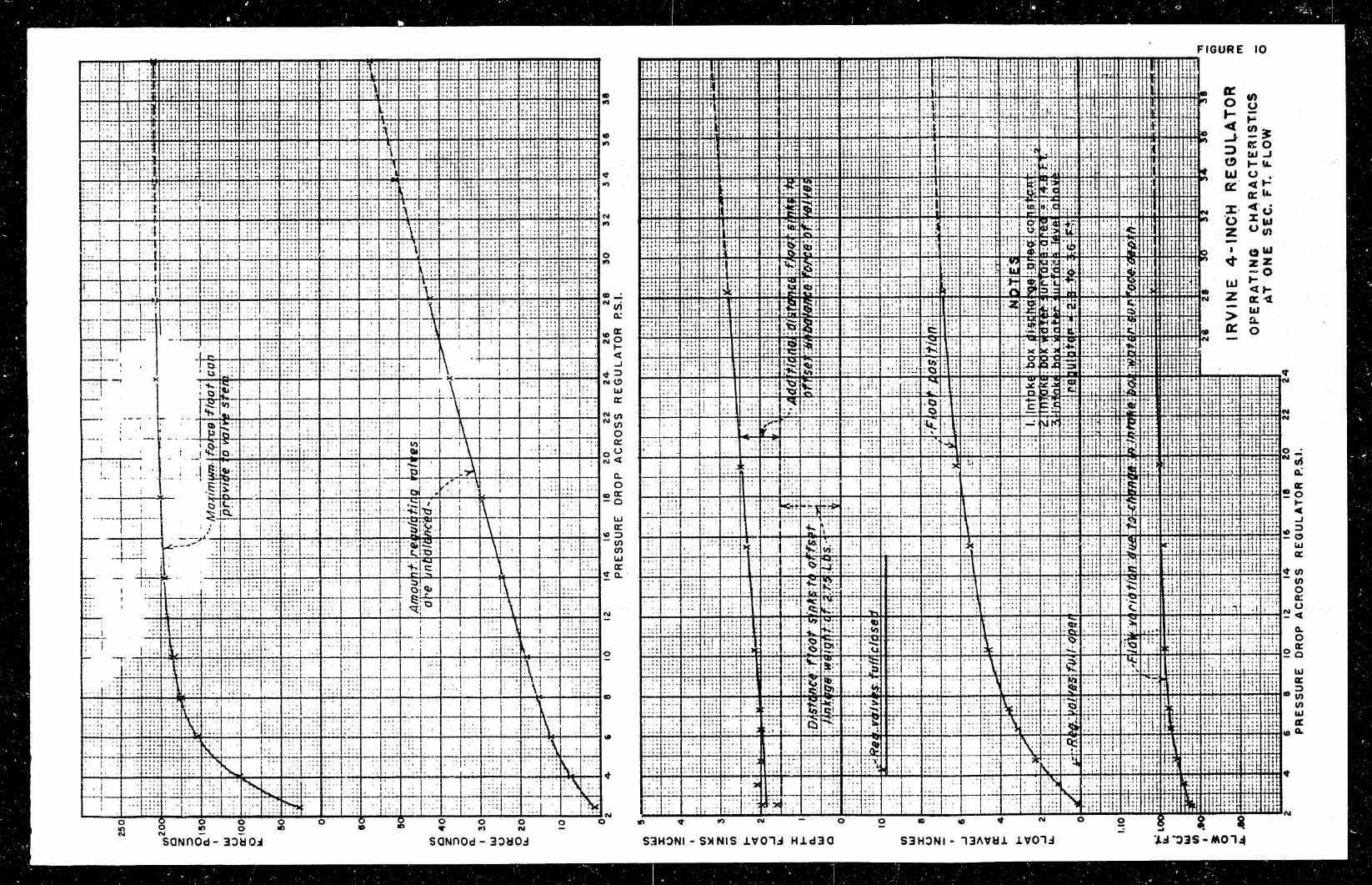
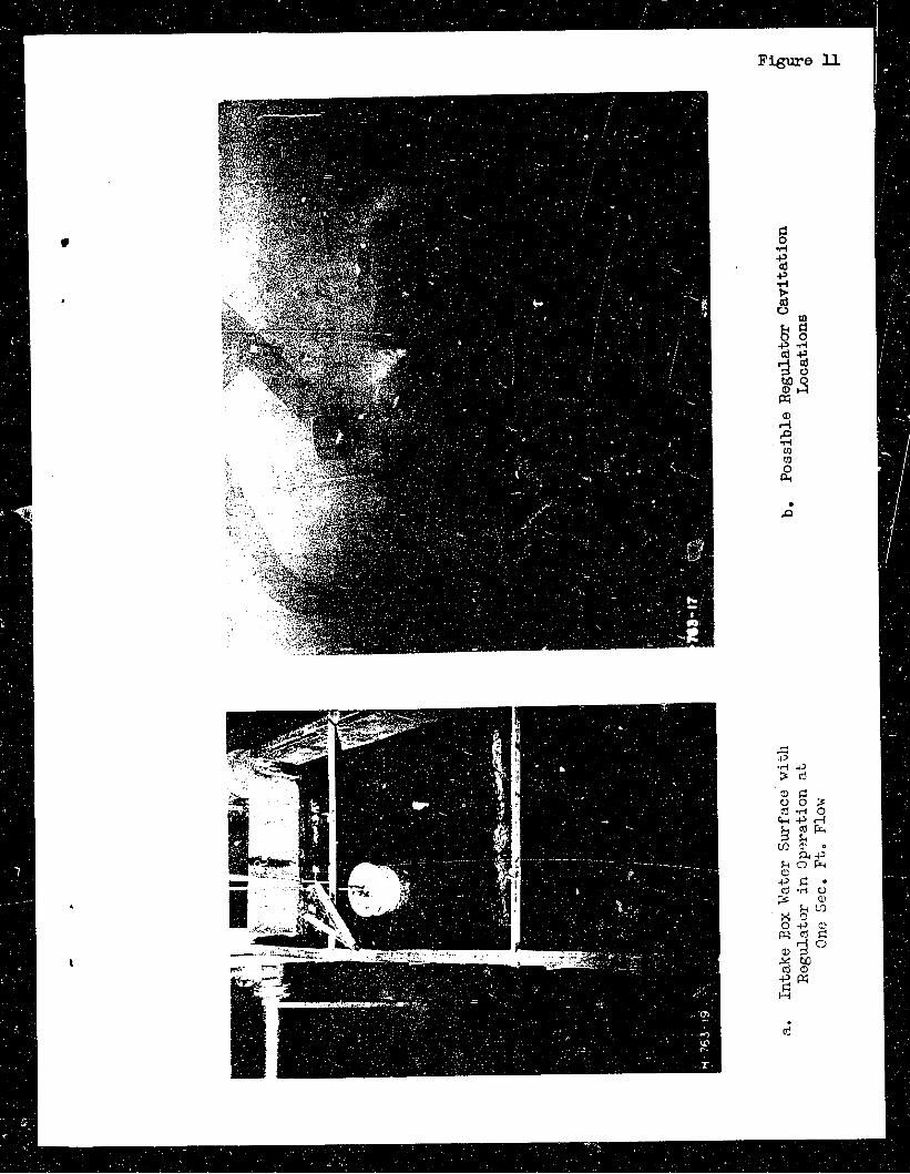
Figure IJ.
fi3 d