Embed Size (px)
Citation preview

UNIT - V
AIRCRAFT INSTRUMENTS

INTRODUCTION
• Enable an airplane to be operated with
maximum performance and enhanced safety
• Manufacturers provide the necessary flight
instruments
• Pilots need to understand how they operate

Types
• Flight Instruments
– Altimeter, Airspeed Indicator, Mach meter, Vertical
Speed Indicator, Attitude Indicator (Artificial
Horizon), Turn and Bank Indicator , Heading Indicator
• Navigation Instruments
– Accelerometer, Horizontal Situation Indicator
• Engine Instruments
– Electrical Tachometer, Oil Pressure Indicator, Exhaust
Gas Temperature,
• Pressure Gauges
– Bourdon Tube , Diaphragm Type ,Hydraulic

Flight Instruments
• They provide the pilot with information about
the flight situation of that aircraft, such as
altitude, speed and direction.
• Used in conditions of poor visibility, such as in
clouds, when such information is not available
from visual reference outside the aircraft.

Flight Instruments
Airspeed Indicator, Attitude Indicator, Altimeter,
Turn and Bank Indicator, Heading Indicator, Vertical Speed Indicator

Pitot-Static Flight Instruments
• Two Major Parts:
– Impact Pressure Chamber and Lines
– Static Pressure Chamber and Lines

Blockage of Pitot-Static System

ALTIMETER

Effect of Temperature on an Altimeter
Types of Altitude
• Indicated Altitude : Altitude read directly from the altimeter (uncorrected)
• True Altitude : The vertical distance of the airplane above sea level—the actual altitude. It is often expressed as feet above mean sea level (MSL). Airport, terrain, and obstacle elevations on aeronautical charts are true altitudes.
• Absolute Altitude : The vertical distance of an airplane above the terrain, or above ground level (AGL).

Types of Altitude • Pressure Altitude : The altitude indicated when the
altimeter setting window (barometric scale) is adjusted to 29.92 in. Hg (Corrected to 15°C). Pressure altitude is used to compute density altitude, true altitude, true airspeed, and other performance data.
• Density Altitude : Pressure altitude corrected for variations from standard temperature. When conditions are standard, pressure altitude and density altitude are the same. If the temperature is above standard, the density altitude is higher than pressure altitude. If the temperature is below standard, the density altitude is lower than pressure altitude. This is an important altitude because it is directly related to the airplane’s performance.
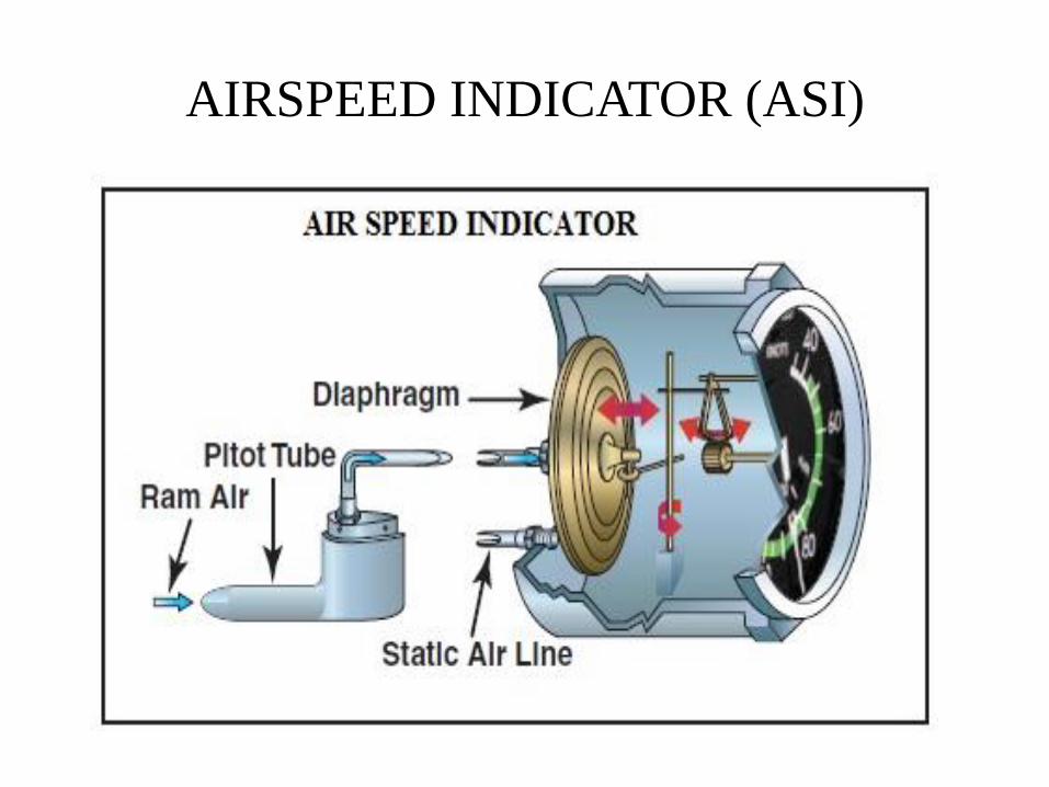
AIRSPEED INDICATOR (ASI)

Types of Airspeeds
• Indicated Airspeed (IAS) : The direct instrument reading obtained from the airspeed indicator, uncorrected for variations in atmospheric density, installation error, or instrument error
• Calibrated Airspeed (CAS) : Indicated airspeed corrected for installation error and instrument error.
• True Airspeed (TAS) : Calibrated airspeed corrected for altitude and nonstandard temperature.
• Groundspeed (GS) : The actual speed of the airplane over the ground. It is true airspeed adjusted for wind. Groundspeed decreases with a headwind, and increases with a tailwind.

ASI – Colour Codes

ASI – Colour Codes • White arc—This arc is commonly referred to as the flap
operating range since its lower limit represents the full flap stall
speed and its upper limit provides the maximum flap speed.
Approaches and landings are usually flown at speeds within the
white arc.
• Lower limit of white arc (VS0)— The stalling speed or the
minimum steady flight speed in the landing configuration. In
small airplanes, this is the power-off stall speed at the maximum
landing weight in the landing configuration (gear and flaps
down).
• Upper limit of the white arc (VFE)—The maximum speed with
the flaps extended.
• Green arc—This is the normal operating range of the airplane.
Most flying occurs within this range.

ASI – Colour Codes
• Lower limit of green arc (VS1)—The stalling speed or the minimum steady flight speed obtained in a specified configuration. For most airplanes, this is the power-off stall speed at the maximum takeoff weight in the clean configuration (gear up, if retractable, and flaps up).
• Upper limit of green arc (VNO)—The maximum structural cruising speed. Do not exceed this speed except in smooth air.
• Yellow arc—Caution range. Fly within this range only in smooth air, and then, only with caution
.
• Red line (VNE)—Never-exceed speed. Operating above this speed is prohibited since it may result in damage or structural failure.

VERTICAL SPEED INDICATOR (VSI)

IVSI
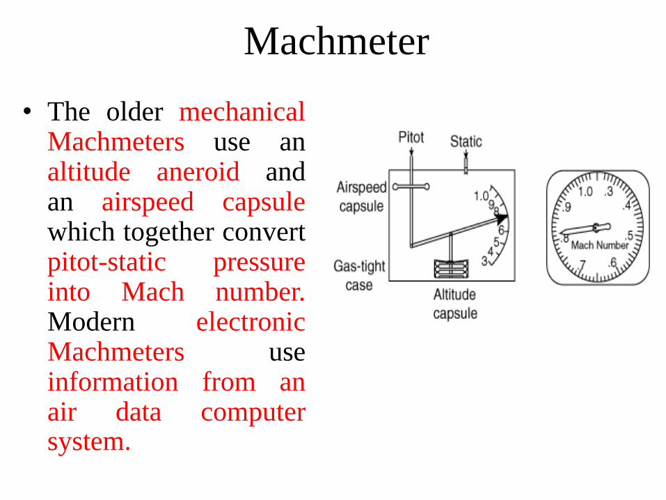
Machmeter
• The older mechanical Machmeters use an altitude aneroid and an airspeed capsule which together convert pitot-static pressure into Mach number. Modern electronic Machmeters use information from an air data computer system.
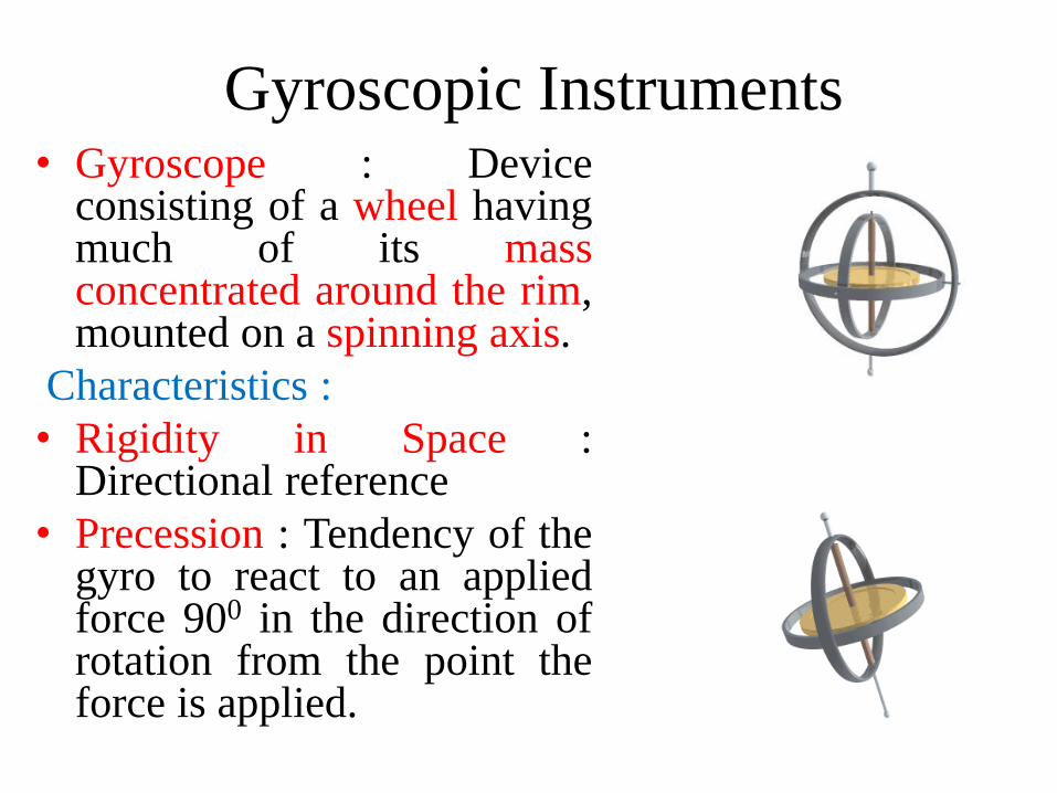
Gyroscopic Instruments • Gyroscope : Device
consisting of a wheel having much of its mass concentrated around the rim, mounted on a spinning axis.
Characteristics :
• Rigidity in Space : Directional reference
• Precession : Tendency of the gyro to react to an applied force 900 in the direction of rotation from the point the force is applied.

Principle
• Rigidity in Space
• Principle that a gyroscope remains in a fixed position in the plane in which it is spinning
• By mounting this wheel, or gyroscope, on a set of Gimbal rings, the gyro is able to rotate freely in any direction.
– If the gimbal rings are tilted, twisted, or otherwise moved, the gyro remains in the plane in which it was originally.
– Think of the gyro as being aligned with the horizon, and the airplane rotates around it.
• Stability increases if the rotor has great mass and speed
– Approximately 15,000 rpm for the attitude indicator and 10,000 rpm for the heading indicator

Principle
• Gyroscopic Precession
Whenever a force attempts to tilt the plane of rotation, the force is applied 90 degrees ahead of, and in the direction of rotation
– Inversely proportional to the speed of the rotor and proportional to the deflective force

Power Sources
• Vacuum System:
Runs the Attitude Indicator and Heading Indicator
– Engine Driven Pump creates suction through system
– Air sucked through system is diverted over "buckets" in gyroscope walls to turn gyros
– Semi-frictionless design
Power Sources
• Electrical System:
The turn coordinator uses an electrical gyro so
that in the event of a vacuum system failure,
the pilot still has one working gyroscopic
instrument

Gyroscopic Instruments
• Turn and Bank Indicator
(or) Turn Coordinator
• Attitude Indicator
(or)Artificial Horizon
• Heading Indicator
Turn and Bank Indicator
• Uses an electric gyroscope to give pilot information about rate of turn and rate of roll
– Tells us direction and how quickly we are rolling initially
– Then tells us rate of turn, or how many degrees per second
• Markings at "Standard Rate Turn", which the airplane will turn 360 degrees in 2 minutes
• Gyroscope mounted diagonally, balanced by a spring, and works by precession to sense bank angle
• Inclinometer (ball)
– Separate instrument used to measure quality of turn
– Ball on the inside of turn indicates a slipping turn
– Ball on the outside of turn indicates a skidding turn

Turn and Bank Indicator

Inclinometer
Inclinometer (ball)
Separate instrument used to measure quality of turn
Ball on the inside of turn indicates a slipping turn
Ball on the outside of turn indicates a skidding turn
Attitude Indicator (or) Artificial Horizon
• Provides an artificial horizon to the pilot to
display information about both pitch and bank
• Gyroscope has two gimbals that the aircraft
can rotate about for pitch and bank
• 10,20,30,60,90 degree markings for bank
• Pitch angle is indicated by a series of lines,
each representing 5° or 10° of pitch
• Pilot can set where the miniature airplane
meets the horizon before takeoff

Attitude Indicator

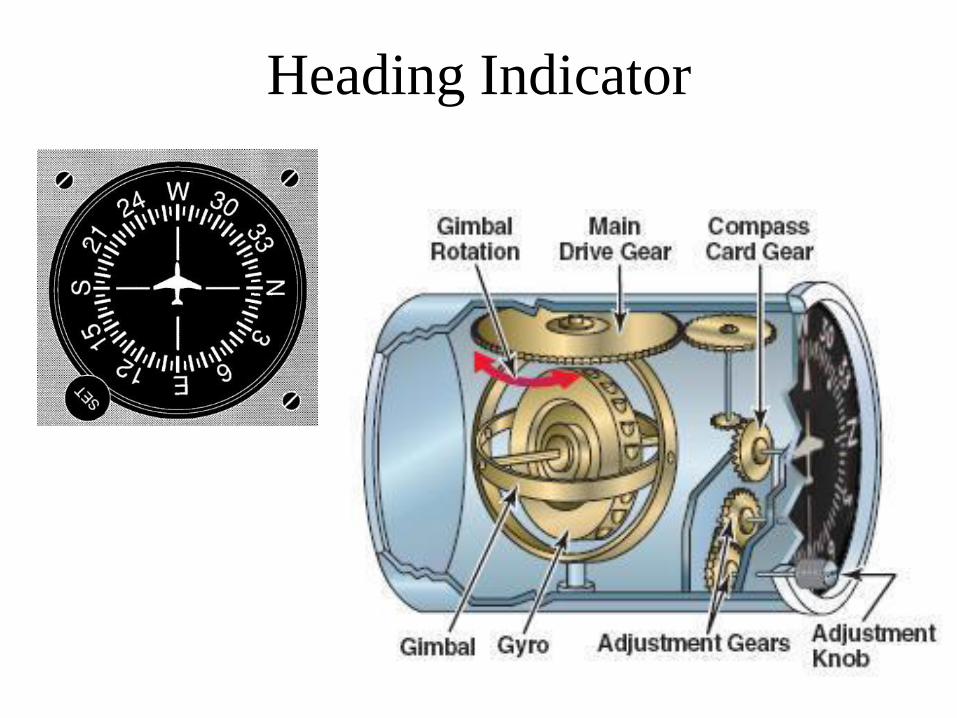
Heading Indicator
• There are a number of errors when using the magnetic compass. The gyroscopic heading indicator makes it easy to turn to headings.
• Unfortunately, the heading indicator does not seek magnetic north by itself
• Vertically mounted gyroscope with one gimbal gives us heading information – We set where the gyroscope considers north with the knob
and it tells us heading as we rotate around it.
]Errors
• Drift – Because the earth rotates and because of small accumulated
errors caused by friction and imperfect balancing of the gyro, the Heading Indicator will drift over time
– Must be set every 15 min
Heading Indicator
NAVIGATION INSTRUMENTS

Accelerometer
• It is used on new airplanes during test flights to
measure the acceleration loads on the aircraft structure.
• Serves as the basis for stress analysis as it gives an
accurate indication of stresses imposed on airplane
during flight.
• It measures accelerations exerted on airplane in gravity
units.
• It indicates change only along the aircraft vertical axis
• It is graduated in gravity units from -5g to +12g.
• Vertical acceleration can be illustrated by carrying a
heavy parcel in elevator

Accelerometer

Horizontal Situation Indicator (HSI)
• It combines the information supplied by heading indicator with radio navigation information(VOR/ILS)
• It reduces eye motion of pilot
• Electrically or Pneumatically driven gyro for heading indicator
• Information from navigation radio is displayed through a deviation bar and selected course pointer
• When gyro is operating properly, the flag (NAV, HDG, GS) is retracted out of sight

HSI
ENGINE INSTRUMENTS

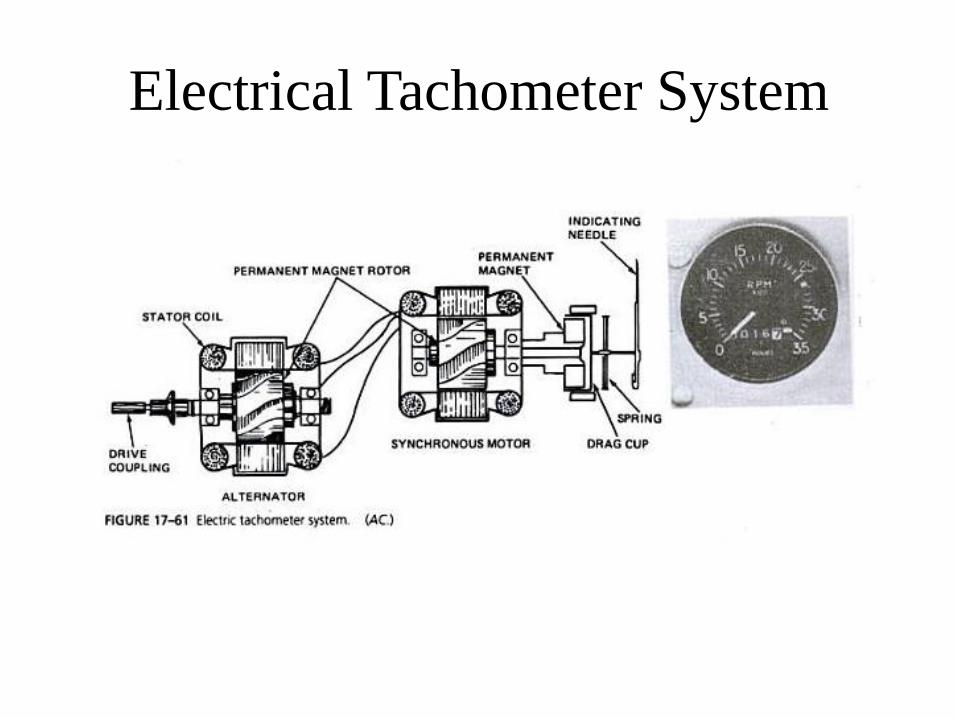
Electrical Tachometer System
• They are used on large aircraft – distance from engine
to instrument panel makes Mechanical tachometer
impractical
• 3 phase AC alternator to generate signal
• The signal drives a synchronous motor inside the
instrument – the motor synchronizes its speed with
alternator
• The motor turns the drag cup
• Drag cup positions the needle on the face of the
instrument
Electrical Tachometer System

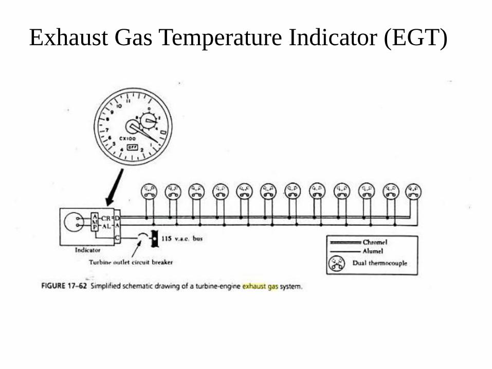
Exhaust Gas Temperature Indicator (EGT)
• It is a primary instrument for monitoring turbine
engine operation
• They are used to monitor the performance of the
engines and make flight and maintenance
adjustments.
• The system operate by placing thermocouples in the
stream of exhaust gases exiting the engine.
• The thermocouple generate the current, which drives
the indicator.
• The amount of current is very low and is amplified or
adjusted in order to drive the indicator display.

Exhaust Gas Temperature Indicator (EGT)
• If Multiple probes are used, a selector switch
on the instrument is used to allow selection of
the cylinder being monitored.
• In turbine engine, system uses several probes
in parallel.
• The average reading of the temperature and the
indication does not change substantially if one
probe should fail.
Exhaust Gas Temperature Indicator (EGT)

Oil Pressure Indicator
• It can be mechanically operated or electrically
powered.
• A Mechanically operated gauge uses an oil-pressure
line from the engine to the instrument to operate a
bourdon tube and gear segment to position the
indicator needle.
• Restrictor in oil line prevent rapid oil loss if line
breaks.
• Light oil is used in line between gauge and engine for
quick response.

Oil Pressure Indicator
• Electric oil pressure sensors use pressure sensor on
the engine, it varies its resistance as pressure changes.
• The pressure signal generated is processed and
indicated in the cockpit display.

PRESSURE GAUGES

Bourdon – Tube Pressure Gauge
• The bourdon tube is made of spring tempered brass, bronze or
beryllium copper.
• They have strong spring effect that cause the bourdon tube to
return to its original position when pressure is released.
• When pressure enters the bourdon tube, the tube tends to
straighten out
• This move the mechanical linkage connected to the sector gear
• The movement of sector gear causes spur gear to rotate and in
turn moves the indicating needle along the scale.

Bourdon – Tube Pressure Gauge

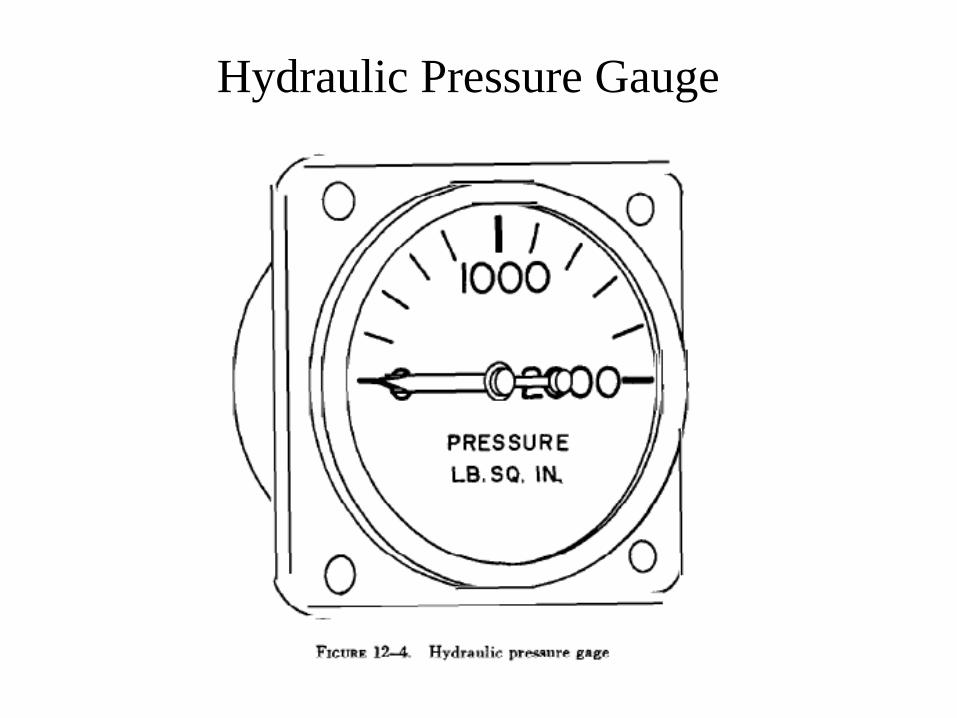
Hydraulic Pressure Gauge
• A pressure gauge to measure the differential pressure in
the hydraulic system indicates how this system is
functioning.
• Hydraulic pressure gauges are designed to indicate either
the pressure of the complete system or the pressure of an
individual unit in the system.
• The case of this gauge contains a Bourdon tube and a
gear-and-pinion mechanism by which the Bourdon
tube’s motion is amplified and transferred to the pointer.
• The position of the pointer on the calibrated dial
indicates the hydraulic pressure in p.s.i.
Hydraulic Pressure Gauge
Diaphragm Type Pressure Gauge
• It is a differential- pressure measuring device
• They use a diaphragm for measuring pressure
• The pressure or suction to be measured is admitted to the
pressure-sensitive diaphragm through an opening in the
back of the instrument case
• An opposing pressure, such as that of the atmosphere, is
admitted through a vent in the case

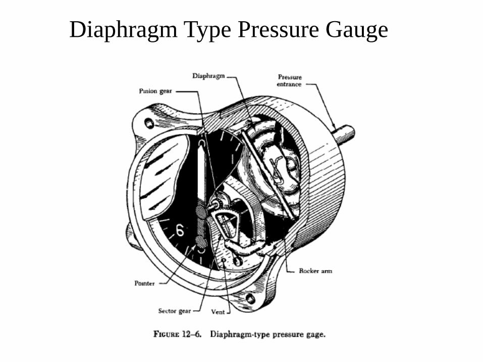
Diaphragm Type Pressure Gauge
• The walls of the diaphragm are very thin, an increase of
pressure will cause it to expand, and a decrease in
pressure will cause it to contract.
• Any movement of the diaphragm is transferred to the
pointer by means of the rocker shaft, sector, and pinion,
which are connected to the front side of the diaphragm.
Diaphragm Type Pressure Gauge