Embed Size (px)
Citation preview

Course Material –Lecture Notes
CS 6551 Computer Networks – Unit-III Page 1
UNIT III
ROUTING
Routing (RIP, OSPF, and metrics): Routing is the process of selecting best paths in a network. In the past, the term routing
was also used to mean forwarding network traffic among networks. However this latter function is much better described as simply forwarding. Routing is performed for many kinds of networks, including the telephone network (circuit switching), electronic data networks (such as the Internet), and transportation networks.
RIP :
Information Protocol (RIP) is one of the oldest distance-vector routing protocols, which employs the hop count as a routing metric. RIP prevents routing loops by implementing a limit on the number of hops allowed in a path from the source to a destination. The maximum number of hops allowed for RIP is 15. This hop limit, however, also limits the size of networks that RIP can support. A hop count of 16 is considered an infinite distance, in other words the route is considered unreachable. RIP implements the split horizon, route poisoning and hold down mechanisms to prevent incorrect routing information from being propagated.
Originally, each RIP router transmitted full updates every 30 seconds. In the early deployments, routing tables were small enough that the traffic was not significant. As networks grew in size, however, it became evident there could be a massive traffic burst every 30 seconds, even if the routers had been initialized at random times.
Versions
There are three versions of the Routing Information Protocol: RIPv1, RIPv2, and RIPng.
RIP version 1
The original specification of RIP, defined in RFC 1058,[3] was published in 1988 and uses classful routing. The periodic routing updates do not carry subnet information, lacking support
WWW.STUDENTSFOCUS.COM
www.studentsfocus.com

Course Material –Lecture Notes
CS 6551 Computer Networks – Unit-III Page 2
for variable length subnet masks (VLSM). This limitation makes it impossible to have different-sized subnets inside of the same network class. In other words, all subnets in a network class must have the same size. There is also no support for router authentication, making RIP vulnerable to various attacks.
RIP version 2
Due to the deficiencies of the original RIP specification, RIP version 2 (RIPv2) was developed in 1993[4] and last standardized in 1998.[4] It included the ability to carry subnet information, thus supporting Classless Inter-Domain Routing (CIDR). To maintain backward compatibility, the hop count limit of 15 remained. RIPv2 has facilities to fully interoperate with the earlier specification if all Must Be Zero protocol fields in the RIPv1 messages are properly specified. In addition, a compatibility switch feature[4] allows fine-grained interoperability adjustments.
In an effort to avoid unnecessary load on hosts that do not participate in routing, RIPv2 multicasts the entire routing table to all adjacent routers at the address 224.0.0.9, as opposed to RIPv1 which uses broadcast. Unicast addressing is still allowed for special applications.
(MD5) authentication for RIP was introduced in 1997.
RIPv2 is Internet Standard STD56 (which is RFC 2453).
Route tags were also added in RIP version 2. This functionality allows a distinction between routes learned from the RIP protocol and routes learned from other protocols.
RIPng
RIPng (RIP next generation), defined in RFC 2080,[7] is an extension of RIPv2 for support of IPv6, the next generation Internet Protocol. The main differences between RIPv2 and RIPng are:
x Support of IPv6 networking. x While RIPv2 supports RIPv1 updates authentication, RIPng does not. IPv6 routers were,
at the time, supposed to use IPsec for authentication. x RIPv2 encodes the next-hop into each route entry, RIPng requires specific encoding of
the next hop for a set of route entries.
RIPng sends updates on UDP port 521 using the multicast group FF02::9.
RIPv1 Operation
RIP defines two types of messages.
1. Request Message 2. Response Message
WWW.STUDENTSFOCUS.COM
www.studentsfocus.com
Course Material –Lecture Notes
CS 6551 Computer Networks – Unit-III Page 3
When a RIP router comes online, it sends a broadcast Request Message on all of its RIP enabled interfaces. All the neighbouring routers which receive the Request message respond back with the Response Message containing their Routing table. The Response Message is also gratuitously sent when the Update timer expires. On receiving the Routing table, the router processes each entry of the routing table as per the following rules
1. If there are no route entry matching the one received then the route entry is added to the routing table automatically, along with the information about the router from which it received the routing table
2. If there are matching entry but the hop count metric is lower than the one already in its routing table, then the routing table is updated with the new route.
3. If there are matching entry but the hop count metric is higher than the one already in its routing table, then the routing entry is updated with hop count of 16 (infinite hop). The packets are still forwarded to the old route. A Holddown timer is started and all the updates for that from other routers are ignored. If after the Holddown timer expires and still the router is advertising with the same higher hop count then the value is updated into its routing table. Only after the timer expires, the updates from other routers are accepted for that route.
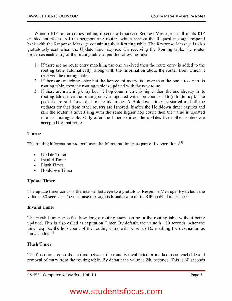
Timers
The routing information protocol uses the following timers as part of its operation:-[8]
x Update Timer x Invalid Timer x Flush Timer x Holddown Timer
Update Timer
The update timer controls the interval between two gratuitous Response Message. By default the value is 30 seconds. The response message is broadcast to all its RIP enabled interface.[8]
Invalid Timer
The invalid timer specifies how long a routing entry can be in the routing table without being updated. This is also called as expiration Timer. By default, the value is 180 seconds. After the timer expires the hop count of the routing entry will be set to 16, marking the destination as unreachable.[8]
Flush Timer
The flush timer controls the time between the route is invalidated or marked as unreachable and removal of entry from the routing table. By default the value is 240 seconds. This is 60 seconds
WWW.STUDENTSFOCUS.COM
www.studentsfocus.com

Course Material –Lecture Notes
CS 6551 Computer Networks – Unit-III Page 4
longer than Invalid timer. So for 60 seconds the router will be advertising about this unreachable route to all its neighbours. This timer must be set to a higher value than the invalid timer. [8]
Hold-down Timer
The hold-down timer is started per route entry, when the hop count is changing from lower value to higher value. This allows the route to get stabilized. During this time no update can be done to that routing entry. This is not part of the RFC 1058. This is Cisco's implementation. The default value of this timer is 180 seconds.[8]
Limitations
x The hop count cannot exceed 15, or routes will be dropped. x Most RIP networks are flat. There is no concept of areas or boundaries in RIP networks
(but aggregation is possible). x Variable Length Subnet Masks are not supported by RIP version 1 (which is obsolete). x RIP has slow convergence and count to infinity problems.[citation needed]
OSPF:
Open Shortest Path First (OSPF) is a routing protocol for Internet Protocol (IP) networks. It uses a link state routing algorithm and falls into the group of interior routing protocols, operating within a single autonomous system (AS). It is defined as OSPF Version 2 in RFC 2328 (1998) for IPv4.[1] The updates for IPv6 are specified as OSPF Version 3 in RFC 5340 (2008).[2]
x OSPF is perhaps the most widely used interior gateway protocol (IGP) in large enterprise networks. Intermediate System to Intermediate System (IS-IS), another link-state dynamic routing protocol, is more common in large service provider networks. The most widely used exterior gateway protocol is the Border Gateway Protocol (BGP), the principal routing protocol between autonomous systems on the Internet.
OSPF router within a network communicates with other neighboring routers on each connecting interface to establish the states of all adjacencies. Every such communication sequence is a separate conversation identified by the pair of router IDs of the communicating neighbors. RFC 2328 specifies the protocol for initiating these conversations (Hello Protocol) and for establishing full adjacencies (Database Description Packets, Link State Request Packets). During its course, each router conversation transitions through a maximum of eight conditions defined by a state machine:[1][7]
1. Down: The state down represents the initial state of a conversation when no information has been exchanged and retained between routers with the Hello Protocol.
2. Attempt: The Attempt state is similar to the Down state, except that a router is in the process of concerted efforts to establish a conversation with another router, but is only used on NBMA networks.
WWW.STUDENTSFOCUS.COM
www.studentsfocus.com

Srividya College of Engineering and Technology, Virudhunagar. Course Material –Lecture Notes
CS 6551 Computer Networks – Unit-III Page 5
3. Init: The Init state indicates that a HELLO packet has been received from a neighbor, but the router has not established a two-way conversation.
4. 2-Way: The 2-Way state indicates the establishment of a bidirectional conversation between two routers. This state immediately precedes the establishment of adjacency. This is the lowest state of a router that may be considered as a Designated Router.
5. ExStart: The ExStart state is the first step of adjacency of two routers. 6. Exchange: In the Exchange state, a router is sending its link state database information to
the adjacent neighbor. At this state, a router is capable to exchange all OSPF routing protocol packets.
7. Loading: In the Loading state, a router requests the most recent Link-state advertisements (LSAs) from its neighbor discovered in the previous state.
8. Full: The Full state concludes the conversation when the routers are fully adjacent, and the state appears in all router- and network-LSAs. The link state databases of the neighbors are fully synchronized.
Protocol messages
Unlike other routing protocols, OSPF does not carry data via a transport protocol, such as the User Datagram Protocol (UDP) or the Transmission Control Protocol (TCP). Instead, OSPF forms IP datagrams directly, packaging them using protocol number 89 for the IP Protocol field. OSPF defines five different message types, for various types of communication:
Hello
Hello messages are used as a form of greeting, to allow a router to discover other adjacent routers on its local links and networks. The messages establish relationships between neighboring devices (called adjacencies) and communicate key parameters about how OSPF is to be used in the autonomous system or area.
Database Description
Database Description messages contain descriptions of the topology of the autonomous system or area. They convey the contents of the link-state database (LSDB) for the area from one router to another. Communicating a large LSDB may require several messages to be sent by having the sending device designated as a master device and sending messages in sequence, with the slave (recipient of the LSDB information) responding with acknowledgements.
Link State Request
These messages are used by one router to request updated information about a portion of the LSDB from another router. The message specifies exactly which link(s) about which the requesting device wants more current information.
www.studentsfocus.com

Srividya College of Engineering and Technology, Virudhunagar. Course Material –Lecture Notes
CS 6551 Computer Networks – Unit-III Page 6
Link State Update
These messages contain updated information about the state of certain links on the LSDB. They are sent in response to a Link State Request message, and also broadcast or multicast by routers on a regular basis. Their contents are used to update the information in the LSDBs of routers that receive them.
Link State Acknowledgment
These messages provide reliability to the link-state exchange process, by explicitly acknowledging receipt of a Link State Update message.
Switch basics:
Ethernet switches link Ethernet devices together by relaying Ethernet frames between the devices connected to the switches. By moving Ethernet frames between the switch ports, a switch links the traffic carried by the individual network connections into a larger Ethernet network.
Ethernet switches perform their linking function by bridging Ethernet frames between Ethernet segments. To do this, they copy Ethernet frames from one switch port to another, based on the Media Access Control (MAC) addresses in the Ethernet frames. Ethernet bridging was initially defined in the 802.1D IEEE Standard for Local and Metropolitan Area Networks: Media Access Control (MAC) Bridges.[1]
The standardization of bridging operations in switches makes it possible to buy switches from different vendors that will work together when combined in a network design. That’s the result of lots of hard work on the part of the standards engineers to define a set of standards that vendors could agree upon and implement in their switch designs.
Bridges and Switches
The first Ethernet bridges were two-port devices that could link two of the original Ethernet system’s coaxial cable segments together. At that time, Ethernet only supported connections to coaxial cables. Later, when twisted-pair Ethernet was developed and switches with many ports became widely available, they were often used as the central connection point, or hub, of Ethernet cabling systems, resulting in the name “switching hub.” Today, in the marketplace, these devices are simply called switches.
Things have changed quite a lot since Ethernet bridges were first developed in the early 1980s. Over the years, computers have become ubiquitous, and many people use multiple devices at their jobs, including their laptops, smartphones, and tablets. Every VoIP telephone and every printer is a computer, and even building management systems and access controls (door locks) are networked. Modern buildings have multiple wireless access points (APs) to provide 802.11 Wi-Fi services for things like smartphones and tablets, and each of the APs is also connected to a cabled Ethernet system.
www.studentsfocus.com

Srividya College of Engineering and Technology, Virudhunagar. Course Material –Lecture Notes
CS 6551 Computer Networks – Unit-III Page 7
Operation of Ethernet Switches
Networks exist to move data between computers. To perform that task, the network software organizes the data being moved into Ethernet frames. Frames travel over Ethernet networks, and the data field of a frame is used to carry data between computers. Frames are nothing more than arbitrary sequences of information whose format is defined in a standard.
The format for an Ethernet frame includes a destination address at the beginning, containing the address of the device to which the frame is being sent.[2] Next comes a source address, containing the address of the device sending the frame. The addresses are followed by various other fields, including the data field that carries the data being sent between computers.
Operation of Ethernet Switches
Networks exist to move data between computers. To perform that task, the network software organizes the data being moved into Ethernet frames. Frames travel over Ethernet networks, and the data field of a frame is used to carry data between computers. Frames are nothing more than arbitrary sequences of information whose format is defined in a standard.
The format for an Ethernet frame includes a destination address at the beginning, containing the address of the device to which the frame is being sent.[2] Next comes a source address, containing the address of the device sending the frame. The addresses are followed by various other fields, including the data field that carries the data being sent between computers, as shown in Figure 1-1.
Ethernet frame format
Frames are defined at Layer 2, or the Data Link Layer, of the Open Systems Interconnection (OSI) seven-layer network model. The seven-layer model was developed to organize the kinds of information sent between computers. It is used to define how that information will be sent and to structure the development of standards for transferring information. Since Ethernet switches operate on local area network frames at the Data Link Layer, you will sometimes hear them called link layer devices, as well as Layer 2 devices or Layer 2 switches.[3]
www.studentsfocus.com

Srividya College of Engineering and Technology, Virudhunagar. Course Material –Lecture Notes
CS 6551 Computer Networks – Unit-III Page 8
Global Internet Areas:
• Especially used with OSPF.
• Sub-domains of larger domains.
• One special area called backbone area. (Area 0).
• Within each area -- link state routing.
• Link state advertisements of non border routers do not leave area.
• Packet goes from non-backbone area to backbone area and crosses the backbone into the Internet.
•
Area 1Area 0
Area 3
Area 2
R9
R8
R7R1
R5R6
R4
R3
R2
A router that is a member of both the backbone and a non-backbone area (R1) is called a area router.
• Border routers “summarize” routing information and make it available to other areas -- act like proxies --reflect costs to reach networks from an area.
• When there are many possible routes, routers choose cost info to forward packets.
• Trade-offs -- Optimality versus scalability -- All packet have to pass through the backbone area (may not be optimal).
www.studentsfocus.com

Srividya College of Engineering and Technology, Virudhunagar. Course Material –Lecture Notes
CS 6551 Computer Networks – Unit-III Page 9
Border Gateway Protocol (BGP) is a standardized exterior gateway protocol designed to exchange routing and reachability information between autonomous systems (AS) on the Internet.[1] The protocol is often classified as a path vector protocol but is sometimes also classed as a distance-vector routing protocol.
• BGP supports flexibility -- paths could be chosen by a provider based on a policy.
• To configure BGP, each AS admin picks at least one node to be the “BGP” speaker -- a spokesperson node for the entire AS.
– The BGP speaker establishes a BGP session with other BGP speakers in other ASes.
• In addition, there are border gateways using which packets enter/leave ASes.
• Source advertises complete paths (unlike distance vector or link state routing) -- thus loops are prevented.
•
Regional provider A(AS 2)
Regional provider B(AS 3)
Customer P(AS 4)
Customer Q(AS 5)
Customer R(AS 6)
Customer S(AS 7)
128.96192.4.153
192.4.32192.4.3
192.12.69
192.4.54192.4.23
Backbone network(AS 1)
AS 2 says 128.96, 192.4.15, 192.4.32, 192.4.3 can be reached via AS 2.
• AS 1 advertises that these networks can be reached via <AS1, AS2> --note full path description.
• Loops are avoided.
www.studentsfocus.com

Srividya College of Engineering and Technology, Virudhunagar. Course Material –Lecture Notes
CS 6551 Computer Networks – Unit-III Page 10
BGP Messages: BGP has four types of messages
– OPEN: Establish a connection with a BGP peer
• Note: BGP connection is TCP based ! (Port no. 179).
– UPDATE -- advertise or withdraw routes to a destination
• Note --BGP speaker needs to be able to cancel previously advertised paths if nodes or links fail. This form of negative advertisements are said to advertise “withdrawn routes”.
• KEEPALIVE: Inform a peer that the sender is still alive but has no information to send.
• NOTIFICATION: Notify that errors are detected.
• 16 byte fields.
• For more detail look at book.
• Important thing --- BGP updates are of the type prefix/length
– 192.4.16/20
• Note that forwarding entries can also be similarly represented.
0 15
Unfeasible routeslength
Withdrawn routes(variable)
Total pathattribute length
Path attributes(variable)
Network layerreachability info
(variable)
www.studentsfocus.com

Srividya College of Engineering and Technology, Virudhunagar. Course Material –Lecture Notes
CS 6551 Computer Networks – Unit-III Page 11
Routing with BGP:
• For stub AS -- border router injects a default route into the intra-domain routing protocol.
• If there are more than one border router, each injects specific routes that they have learned from outside the AS.
• IBGP or Interior BGP is used to distribute the information to all other routers in the domain (and the speaker).
Global Internet IPv6:
IPv6 features: The next generation networks based on IPv6 will provide:
•128 bit wide address space to cover all possible appliances connectivity •Differentiated Services in terms of quality (bandwidth guarantee and transit delays for real time flows). •Security in terms of access point authentication, message integrity and privacy. •Auto-configuration and reconfiguration capabilities allowing easy modification of network architectures. •Management facilities allowing the setting up of on-demand services and pr o- viding ISPs with accounting capacities. •Wide range of applications and services. •Mobile host capabilities allowing provision of transparent access whatever the physical access used, supporting the evolving UMTS capabilities, will be the issue of co-operation between the mobile IP related projects (e.g. WINE). Multicast – addresses
A multicast address is a logical identifier for a group of hosts in a computer network, that are available to process datagrams or frames intended to be multicast for a designated network service. Multicast addressing can be used in the Link Layer (Layer 2 in the OSI model), such as Ethernet multicast, and at the Internet Layer (Layer 3 for OSI) for Internet Protocol Version 4 (IPv4) or Version 6 (IPv6) multicast.
IP multicast address Description
224.0.0.0 Base address (reserved)
224.0.0.1 The All Hosts multicast group addresses all hosts on the same network segment.
224.0.0.2 The All Routers multicast group addresses all routers on the same network segment.
224.0.0.4 This address is used in the Distance Vector Multicast Routing Protocol (DVMRP) to
www.studentsfocus.com
Srividya College of Engineering and Technology, Virudhunagar. Course Material –Lecture Notes
CS 6551 Computer Networks – Unit-III Page 12
address multicast routers.
224.0.0.5 The Open Shortest Path First (OSPF) All OSPF Routers address is used to send Hello packets to all OSPF routers on a network segment.
224.0.0.6 The OSPF All Designated Routers ""(DR)"" address is used to send OSPF routing information to designated routers on a network segment.
224.0.0.9 The Routing Information Protocol (RIP) version 2 group address is used to send routing information to all RIP2-aware routers on a network segment.
224.0.0.10 The Enhanced Interior Gateway Routing Protocol (EIGRP) group address is used to send routing information to all EIGRP routers on a network segment.
224.0.0.13 Protocol Independent Multicast (PIM) Version 2
224.0.0.18 Virtual Router Redundancy Protocol (VRRP)
224.0.0.19 - 21 IS-IS over IP
224.0.0.22 Internet Group Management Protocol (IGMP) version 3[2]
224.0.0.102 Hot Standby Router Protocol version 2 (HSRPv2) / Gateway Load Balancing Protocol (GLBP)
224.0.0.107 Precision Time Protocol (PTP) version 2 peer delay measurement messaging
224.0.0.251 Multicast DNS (mDNS) address
224.0.0.252 Link-local Multicast Name Resolution (LLMNR) address
224.0.0.253 Teredo tunneling client discovery address[3]
224.0.1.1 Network Time Protocol clients listen on this address for protocol messages when operating in multicast mode.
224.0.1.22 Service Location Protocol version 1 general
224.0.1.35 Service Location Protocol version 1 directory agent
224.0.1.39 The Cisco multicast router AUTO-RP-ANNOUNCE address is used by RP mapping agents to listen for candidate announcements.
224.0.1.40 The Cisco multicast router AUTO-RP-DISCOVERY address is the destination
www.studentsfocus.com
Srividya College of Engineering and Technology, Virudhunagar. Course Material –Lecture Notes
CS 6551 Computer Networks – Unit-III Page 13
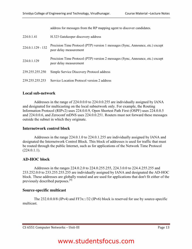
address for messages from the RP mapping agent to discover candidates.
224.0.1.41 H.323 Gatekeeper discovery address
224.0.1.129 - 132 Precision Time Protocol (PTP) version 1 messages (Sync, Announce, etc.) except peer delay measurement
224.0.1.129 Precision Time Protocol (PTP) version 2 messages (Sync, Announce, etc.) except peer delay measurement
239.255.255.250 Simple Service Discovery Protocol address
239.255.255.253 Service Location Protocol version 2 address
Local sub-network
Addresses in the range of 224.0.0.0 to 224.0.0.255 are individually assigned by IANA and designated for multicasting on the local subnetwork only. For example, the Routing Information Protocol (RIPv2) uses 224.0.0.9, Open Shortest Path First (OSPF) uses 224.0.0.5 and 224.0.0.6, and Zeroconf mDNS uses 224.0.0.251. Routers must not forward these messages outside the subnet in which they originate.
Internetwork control block
Addresses in the range 224.0.1.0 to 224.0.1.255 are individually assigned by IANA and designated the Internetwork Control Block. This block of addresses is used for traffic that must be routed through the public Internet, such as for applications of the Network Time Protocol (224.0.1.1).
AD-HOC block
Addresses in the ranges 224.0.2.0 to 224.0.255.255, 224.3.0.0 to 224.4.255.255 and 233.252.0.0 to 233.255.255.255 are individually assigned by IANA and designated the AD-HOC block. These addresses are globally routed and are used for applications that don't fit either of the previously described purposes.[4]
Source-specific multicast
The 232.0.0.0/8 (IPv4) and FF3x::/32 (IPv6) block is reserved for use by source-specific multicast.
www.studentsfocus.com

Srividya College of Engineering and Technology, Virudhunagar. Course Material –Lecture Notes
CS 6551 Computer Networks – Unit-III Page 14
GLOP addressing
The 233.0.0.0/8 range was originally assigned by RFC 2770 as an experimental, public statically assigned multicast address space for publishers and Internet service providers that wished to source content on the Internet. The allocation method is termed GLOP addressing and provides implementers a block of 255 addresses that is determined by their 16-bit autonomous system number (ASN) allocation.
In a nutshell, the middle two octets of this block are formed from assigned ASNs, giving any operator assigned an ASN 256 globally unique multicast group addresses. The method is not applicable to the newer 32-bit extension AS numbers. RFC 3180, superseding RFC 2770, envisioned the use of the range for many-to-many multicast applications. This block has been one of the most successful multicast addressing schemes.[citation needed] Unfortunately, with only 256 multicast addresses available to each autonomous system, GLOP is not adequate for large-scale broadcasters.[5]
Unicast-Prefix-Based IPv4 Multicast addresses
The 234.0.0.0/8 range is assigned by RFC 6034 as a range of global IPv4 multicast address space provided to each organization that has /24 or larger globally routed unicast address space allocated; one multicast address is reserved per /24 of unicast space. A resulting advantage over GLOP is that the mechanisms in IPv4 and IPv6 become more similar.
Administratively Scoped IPv4 Multicast addresses
The 239.0.0.0/8 range is assigned by RFC 2365 for private use within an organization. From the RFC, packets destined to administratively scoped IPv4 multicast addresses do not cross administratively defined organizational boundaries, and administratively scoped IPv4 multicast addresses are locally assigned and do not have to be globally unique.
The RFC also discusses structuring the 239.0.0.0/8 range to be loosely similar to the scoped IPv6 multicast address range described in RFC 1884.
Multicast routing (DVMRP):
The Distance Vector Multicast Routing Protocol (DVMRP), defined in RFC 1075, is a routing protocol used to share information between routers to facilitate the transportation of IP multicast packets among networks.
www.studentsfocus.com

Course Material –Lecture Notes
CS 6551 Computer Networks – Unit-III Page 15
DVMRP (Distance Vector Multicast Routing Protocol) is the oldest routing protocol that has been used to support multicast data transmission over networks.
DVMRP (Distance Vector Multicast Routing Protocol) is the oldest routing protocol that has been used to support multicast data transmission over networks. The protocol sends multicast data in the form of unicast packets that are reassembled into multicast data at the destination.
DVMRP can run over various types of networks, including Ethernet local area networks (LANs). It can even run through routers that are not multicast-capable. It has been considered as an intermediate solution while "real" multicast Internet Protocol (IP) routing evolves.
Operation
The protocol is based on the RIP protocol.[1] The router generates a routing table with the multicast group of which it has knowledge with corresponding distances (i.e. number of devices/routers between the router and the destination). When a multicast packet is received by a router, it is forwarded by the router's interfaces specified in the routing table.
DVMRP operates via a reverse path flooding technique, sending a copy of a received packet (specifically IGMP messages for exchanging routing information with other routers) out through each interface except the one at which the packet arrived. If a router (i.e. a LAN which it borders) does not wish to be part of a particular multicast group, it sends a "prune message" along the source path of the multicast.
Criticisms
Like most distance-vector protocols, DVMRP has difficulties with network scaling,[2] primarily due to the periodic reflooding necessary to detect new hosts. This was more prevalent in early versions of the protocol, prior to the implementation of pruning.[3] DVMRP's flat unicast routing mechanism, which is used to determine the source interface of a data stream, also affects its ability to scale.
DVMRP is the original IP multicast routing protocol. It was designed to run over both multicast capable LANs (like Ethernet) as well as through non-multicast capable routers. In the case of non-multicast capable routers, the IP multicast packets are "tunneled" through the routers as unicast packets. Because DVMRP replicates the packets, it has an effect on performance, but has provided an intermediate solution for IP multicast routing on the Internet while router vendors decide to support native IP multicast routing.
When configured, DVMRP defaults to enabling all interfaces that are multicast capable.
Multicast routing PIM:
WWW.STUDENTSFOCUS.COM
www.studentsfocus.com

Course Material –Lecture Notes
CS 6551 Computer Networks – Unit-III Page 16
Protocol-Independent Multicast (PIM) is a family of multicast routing protocols for Internet Protocol (IP) networks that provide one-to-many and many-to-many distribution of data over a LAN, WAN or the Internet. It is termed protocol-independent because PIM does not include its own topology discovery mechanism, but instead uses routing information supplied by other routing protocols.
There are four variants of PIM:
x PIM Sparse Mode (PIM-SM) explicitly builds unidirectional shared trees rooted at a rendezvous point (RP) per group, and optionally creates shortest-path trees per source. PIM-SM generally scales fairly well for wide-area usage.[1]
x PIM Dense Mode (PIM-DM) uses dense multicast routing. It implicitly builds shortest-path trees by flooding multicast traffic domain wide, and then pruning back branches of the tree where no receivers are present. PIM-DM is straightforward to implement but generally has poor scaling properties. The first multicast routing protocol, DVMRP used dense-mode multicast routing.[2] See the PIM Internet Standard RFC 3973.
x Bidirectional PIM explicitly builds shared bi-directional trees. It never builds a shortest path tree, so may have longer end-to-end delays than PIM-SM, but scales well because it needs no source-specific state. See Bidirectional PIM Internet Standard RFC 5015.
x PIM Source-Specific Multicast (PIM-SSM) builds trees that are rooted in just one source, offering a more secure and scalable model for a limited amount of applications (mostly broadcasting of content). In SSM, an IP datagram is transmitted by a source S to an SSM destination address G, and receivers can receive this datagram by subscribing to channel (S,G). See informational RFC 3569.
PIM-SM is commonly used in IPTV systems for routing multicast streams between VLANs, Subnets or local area networks
Protocol Independent Multicast - Sparse-Mode (PIM-SM) is a protocol for efficiently routing Internet Protocol (IP) packets to multicast groups that may span wide-area and inter-domain internets. The protocol is named protocol-independent because it is not dependent on any particular unicast routing protocol for topology discovery, and sparse-mode because it is suitable for groups where a very low percentage of the nodes (and their routers) will subscribe to the multicast session. Unlike earlier dense-mode multicast routing protocols such as DVMRP and dense multicast routing which flooded packets across the network and then pruned off branches where there were no receivers, PIM-SM explicitly constructs a tree from each sender to the receivers in the multicast group.[4]
Multicast clients
A router receives explicit Join/Prune messages from those neighboring routers that have downstream group members.
x In order to join a multicast group, G, a host conveys its membership information through the Internet Group Management Protocol (IGMP).
x The router then forwards data packets addressed to a multicast group G to only those interfaces on which explicit joins have been received.
WWW.STUDENTSFOCUS.COM
www.studentsfocus.com

Course Material –Lecture Notes
CS 6551 Computer Networks – Unit-III Page 17
x A Designated Router (DR) sends periodic Join/Prune messages toward a group-specific Rendezvous Point (RP) for each group for which it has active members.
o Note that one router will be automatically or statically designated as the rendezvous point (RP), and all routers must explicitly join through the RP.
x Each router along the path toward the RP builds a wild card (any-source) state for the group and sends Join/Prune messages on toward the RP.
o The term route entry is used to refer to the state maintained in a router to represent the distribution tree.
o A route entry may include such fields as: � source address � the group address � the incoming interface from which packets are accepted � the list of outgoing interfaces to which packets are sent � timers, flag bits, etc.
o The wild card route entry's incoming interface points toward the RP o The outgoing interfaces point to the neighboring downstream routers that have sent
Join/Prune messages toward the RP as well as the directly connected hosts which have requested membership to group G.
x This state creates a shared, RP-centered, distribution tree that reaches all group members.
Multicast sources
x When a data source first sends to a group, its Designated Router (DR) unicasts Register messages to the Rendezvous Point (RP) with the source's data packets encapsulated within.
x If the data rate is high, the RP can send source-specific Join/Prune messages back towards the source and the source's data packets will follow the resulting forwarding state and travel un-encapsulated to the RP.
x Whether they arrive encapsulated or natively, the RP forwards the source's de-capsulated data packets down the RP-centered distribution tree toward group members.
x If the data rate warrants it, routers with local receivers can join a source-specific, shortest path, distribution tree, and prune this source's packets off the shared RP-centered tree.
x For low data rate sources, neither the RP, nor last-hop routers need join a source-specific shortest path tree and data packets can be delivered via the shared RP-tree.
Once the other routers which need to receive those group packets have subscribed, the RP will unsubscribe to that multicast group, unless it also needs to forward packets to another router or node. Additionally, the routers will use reverse-path forwarding to ensure that there are no loops for packet forwarding among routers that wish to receive multicast packets.
WWW.STUDENTSFOCUS.COM
www.studentsfocus.com


![Open Shortest Path First Routing Under Random Early Detectionsd-research.uwaterloo.ca/papers/Networks-OSPF-Routing-with-RED.pdf · First (OSPF) routing protocol [35], where OSPF requires](https://img.dokumen.tips/doc/110x75/5f746308e2e9e43294254a6e/open-shortest-path-first-routing-under-random-early-detectionsd-first-ospf-routing.jpg)