Embed Size (px)
Citation preview

MICROPROCESSORS AND MICROCONTROLLERS MATERIAL
DEPARTMENT OF ECE 1
UNIT – III
OVERVIEW:
Addressing Modes of 8086
Assembler Directives
Procedures and Macros
Instruction Set of 8086
Data Transfer Group
Arithmetic Group
Logical Instructions
Rotate and Shift instructions
Loop Instructions
Conditional and Unconditional instructions
Machine Control and Flag Manipulation instructions
Programming on 8086

MICROPROCESSORS AND MICROCONTROLLERS MATERIAL
DEPARTMENT OF ECE 2
UNIT III
ADDRESSING MODES OF 8086:
Addressing modes indicates way of locating data or operands. Depending upon the data types used
in the instruction and the memory addressing modes, any instruction may belong to one or more
addressing modes. Thus the addressing modes describe the types of operands and the way they are
accessed for executing an instruction.
According to the flow of instruction execution, the instruction may be categorized as:
Sequential Control flow instructions Control Transfer instructions
Sequential Control flow instructions: In this type of instruction after execution control can be
transferred to the next immediately appearing instruction in the program.
The addressing modes for sequential control transfer instructions are as follows:
Immediate addressing mode: In this mode, immediate is a part of instruction and appears in the
form of successive byte or bytes.
Example: MOV CX, 0007H; Here 0007 is the immediate data
Direct Addressing mode: In this mode, the instruction operand specifies the memory address
where data is located.
Example: MOV AX, [5000H]; Data is available in 5000H memory location
Effective Address (EA) is computed using 5000H as offset
address and content of DS as segment address.
EA=10H * DS + 5000H
Register Addressing mode: In this mode, the data is stored in a register and it is referred using
particular register. All the registers except IP may be used in this mode.
Example: MOV AX, BX;
Register Indirect addressing mode: In this mode, instruction specifies a register containing an
address, where data is located. This addressing mode works with SI, DI, BX and BP registers.
Example: MOV AX, [BX]; EA=10H * DS + [BX]
Indexed Addressing mode: 8-bit or 16-bit instruction operand is added to the contents of an index
register (SI or DI), the resulting value is a pointer to location where data resides. DS and ES are

MICROPROCESSORS AND MICROCONTROLLERS MATERIAL
DEPARTMENT OF ECE 3
default segments for index registers SI and DI. DS=0800H, SI=2000H, MOV DL, [SI]
Example: MOV AX, [SI]; EA=10H * DS + [SI]
Register Relative Addressing mode: In this mode, the data is available at an effective address
formed by adding an 8-bit or 16-bit displacement with the content of any one of the registers BX,
BP, SI, DI in the default segments.
Example: MOV AX, 50H [BX]; EA=10H * DS + 50H + [BX]
Based Indexed Addressing mode: In this mode, the contents of a base register (BX or BP) is added
to the contents of an index register (SI or DI), the resulting value is a pointer to location where data
resides.
Example: MOV AX, [BX] [SI]; EA=10H * DS + [BX] + [SI]
MICROPROCESSORS AND MICROCONTROLLERS MATERIAL
DEPARTMENT OF ECE 4
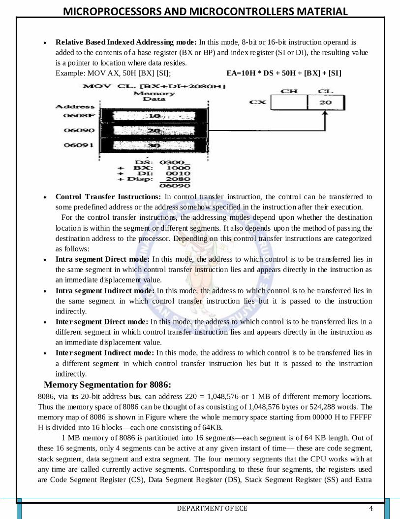
Relative Based Indexed Addressing mode: In this mode, 8-bit or 16-bit instruction operand is
added to the contents of a base register (BX or BP) and index register (SI or DI), the resulting value
is a pointer to location where data resides.
Example: MOV AX, 50H [BX] [SI]; EA=10H * DS + 50H + [BX] + [SI]
Control Transfer Instructions: In control transfer instruction, the control can be transferred to
some predefined address or the address somehow specified in the instruction after their execution.
For the control transfer instructions, the addressing modes depend upon whether the destination
location is within the segment or different segments. It also depends upon the method of passing the
destination address to the processor. Depending on this control transfer instructions are categorized
as follows:
Intra segment Direct mode: In this mode, the address to which control is to be transferred lies in
the same segment in which control transfer instruction lies and appears directly in the instruction as
an immediate displacement value.
Intra segment Indirect mode: In this mode, the address to which control is to be transferred lies in
the same segment in which control transfer instruction lies but it is passed to the instruction
indirectly.
Inter segment Direct mode: In this mode, the address to which control is to be transferred lies in a
different segment in which control transfer instruction lies and appears directly in the instruction as
an immediate displacement value.
Inter segment Indirect mode: In this mode, the address to which control is to be transferred lies in
a different segment in which control transfer instruction lies but it is passed to the instruction
indirectly.
Memory Segmentation for 8086:
8086, via its 20-bit address bus, can address 220 = 1,048,576 or 1 MB of different memory locations.
Thus the memory space of 8086 can be thought of as consisting of 1,048,576 bytes or 524,288 words. The
memory map of 8086 is shown in Figure where the whole memory space starting from 00000 H to FFFFF
H is divided into 16 blocks—each one consisting of 64KB.
1 MB memory of 8086 is partitioned into 16 segments—each segment is of 64 KB length. Out of
these 16 segments, only 4 segments can be active at any given instant of time— these are code segment,
stack segment, data segment and extra segment. The four memory segments that the CPU works with at
any time are called currently active segments. Corresponding to these four segments, the registers used
are Code Segment Register (CS), Data Segment Register (DS), Stack Segment Register (SS) and Extra

MICROPROCESSORS AND MICROCONTROLLERS MATERIAL
DEPARTMENT OF ECE 5
Segment Register (ES) respectively. Each of these four registers is 16-bits wide and user accessible—i.e.,
their contents can be changed by software.
The code segment contains the instruction codes of a program, while data, variables and constants
are held in data segment. The stack segment is used to store interrupt and subroutine return addresses. The
extra segment contains the destination of data for certain string instructions. Thus 64 KB are available for
program storage (in CS) as well as for stack (in SS) while128 KB of space can be utilized for data storage
(in DS and ES).One restriction on the base address (starting address) of a segment is that it must reside on
a 16-byte address memory—examples being 00000 H, 00010 H or 00020 H, etc.
Non overlapping segments overlapping segments
Memory segmentation of 8086
Memory segmentation, as implemented for 8086, gives rise to the following advantages:
Although the address bus is 20-bits in width, memory segmentation allows one to work with
registers having width 16-bits only.
It allows instruction code, data, stack and portion of program to be more than 64 KB long by
using more than one code, data, extra segment and stack segment.
In a time-shared multitasking environment when the program moves over from one user’s
program to another, the CPU will simply have to reload the four segment registers with the
segment starting addresses assigned to the current user’s program.
User’s program (code) and data can be stored separately.
Because the logical address range is from 0000 H to FFFF H, the same can be loaded at any place
in the memory.
Instruction Set of 8086:
There are 117 basic instructions in the instruction set of 8086.The instruction set of 8086 can be divided
into the following number of groups, namely:

MICROPROCESSORS AND MICROCONTROLLERS MATERIAL
DEPARTMENT OF ECE 6
1. Data copy / Transfer instructions 2. Arithmetic and Logical instructions
3. Branch instructions 4. Loop instructions
5. Machine control instructions 6. Flag Manipulation instructions
7. Shift and Rotate instructions 8. String instructions
Data copy / Transfer instructions: The data movement instructions copy values from one location to
another. These instructions include MOV, XCHG, LDS, LEA, LES, PUSH, PUSHF, PUSHFD, POP,
POPF, LAHF, AND SAHF.
MOV The MOV instruction copies a word or a byte of data from source to a destination. The destination
can be a register or a memory location. The source can be a register, or memory location or immediate
data. MOV instruction does not affect any flags.The mov instruction takes several different forms:
Mov reg, reg1; mov mem, reg; mov reg, mem; mov mem, immediate data; mov reg, immediate data;
mov ax/al, mem; mov mem, ax/al; mov segreg, mem16; mov segreg, reg16; mov mem16, segreg; mov
reg16, segreg
The MOV instruction cannot:
1. Set the value of the CS and IP registers.
2. Copy value of one segment register to another segment register (should copy to general register
first). MOV CS, DS (Invalid)
3. Copy immediate value to segment register (should copy to general register first). MOV CS, 2000H
(Invalid)
Example:
ORG 100h
MOV AX, 0B800h; set AX = B800h
MOV DS, AX; copy value of AX to DS.
MOV CL, 'A'; CL = 41h (ASCII code).
The XCHG Instruction: Exchange This instruction exchanges the contents of the specified source and
destination operands, which may be registers or one of them, may be a memory location. However,
exchange of data contents of two memory locations is not permitted.
Example: MOV AL, 5; AL = 5
MOV BL, 2; BL = 2
XCHG AL, BL; AL = 2, BL = 5
PUSH: Push to stack; this instruction pushes the contents of the specified register/memory location on to
the stack. The stack pointer is decremented by 2, after each execution of the instruction. The actual
current stack-top is always occupied by the previously pushed data. Hence, the push operation decrements
SP by two and then stores the two byte contents of the operand onto the stack. The higher b yte is pushed
first and then the lower byte. Thus out of the two decremented stack addresses the higher byte occupies
the higher address and the lower byte occupies the lower address.
1. PUSH AX
2. PUSH DS
3. PUSH [500OH] ; Content of location 5000H and 5001 H in DS are pushed onto the stack.
MICROPROCESSORS AND MICROCONTROLLERS MATERIAL
DEPARTMENT OF ECE 7
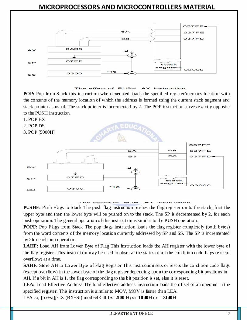
POP: Pop from Stack this instruction when executed loads the specified register/memory location with
the contents of the memory location of which the address is formed using the current stack segment and
stack pointer as usual. The stack pointer is incremented by 2. The POP instruction serves exactly opposite
to the PUSH instruction.
1. POP BX
2. POP DS
3. POP [5000H]
PUSHF: Push Flags to Stack The push flag instruction pushes the flag register on to the stack; first the
upper byte and then the lower byte will be pushed on to the stack. The SP is decremented by 2, for each
push operation. The general operation of this instruction is similar to the PUSH operation.
POPF: Pop Flags from Stack The pop flags instruction loads the flag register completely (both bytes)
from the word contents of the memory location currently addressed by SP and SS. The SP is incremented
by 2for each pop operation.
LAHF: Load AH from Lower Byte of Flag This instruction loads the AH register with the lower byte of
the flag register. This instruction may be used to observe the status of all the condition code flags (except
overflow) at a time.
SAHF: Store AH to Lower Byte of Flag Register This instruction sets or resets the condition code flags
(except overflow) in the lower byte of the flag register depending upon the corresponding bit positions in
AH. If a bit in AH is 1, the flag corresponding to the bit position is set, else it is reset.
LEA: Load Effective Address The load effective address instruction loads the offset of an operand in the
specified register. This instruction is similar to MOV, MOV is faster than LEA.
LEA cx, [bx+si]; CX (BX+SI) mod 64K If bx=2f00 H; si=10d0H cx = 3fd0H
MICROPROCESSORS AND MICROCONTROLLERS MATERIAL
DEPARTMENT OF ECE 8
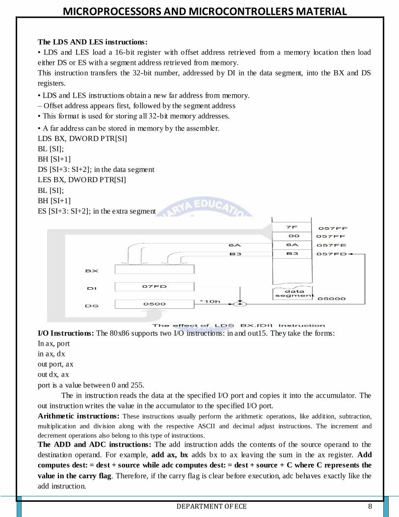
The LDS AND LES instructions:
• LDS and LES load a 16-bit register with offset address retrieved from a memory location then load
either DS or ES with a segment address retrieved from memory.
This instruction transfers the 32-bit number, addressed by DI in the data segment, into the BX and DS
registers.
• LDS and LES instructions obtain a new far address from memory.
– Offset address appears first, followed by the segment address
• This format is used for storing all 32-bit memory addresses.
• A far address can be stored in memory by the assembler.
LDS BX, DWORD PTR[SI]
BL [SI];
BH [SI+1]
DS [SI+3: SI+2]; in the data segment
LES BX, DWORD PTR[SI]
BL [SI];
BH [SI+1]
ES [SI+3: SI+2]; in the extra segment
I/O Instructions: The 80x86 supports two I/O instructions: in and out15. They take the forms:
In ax, port
in ax, dx
out port, ax
out dx, ax
port is a value between 0 and 255.
The in instruction reads the data at the specified I/O port and copies it into the accumulator. The
out instruction writes the value in the accumulator to the specified I/O port.
Arithmetic instructions: These instructions usually perform the arithmetic operations, like addition, subtraction,
multiplication and division along with the respective ASCII and decimal adjust instructions. The increment and
decrement operations also belong to this type of instructions.
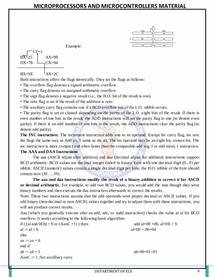
The ADD and ADC instructions: The add instruction adds the contents of the source operand to the
destination operand. For example, add ax, bx adds bx to ax leaving the sum in the ax register. Add
computes dest: = dest + source while adc computes dest: = dest + source + C where C represents the
value in the carry flag. Therefore, if the carry flag is clear before execution, adc behaves exactly like the
add instruction.
MICROPROCESSORS AND MICROCONTROLLERS MATERIAL
DEPARTMENT OF ECE 9
Example:
CF=1
BX=25 AX=98
DX=78 CX=94
BX=9E AX=2C
Both instructions affect the flags identically. They set the flags as follows:
• The overflow flag denotes a signed arithmetic overflow.
• The carry flag denotes an unsigned arithmetic overflow.
• The sign flag denotes a negative result (i.e., the H.O. bit of the result is one).
• The zero flag is set if the result of the addition is zero.
• The auxiliary carry flag contains one if a BCD overflow out of the L.O. nibble occurs.
• The parity flag is set or cleared depending on the parity of the L.O. e ight bits of the result. If there is
even number of one bits in the result, the ADD instructions will set the parity flag to one (to denote even
parity). If there is an odd number of one bits in the result, the ADD instructions clear the parity flag (to
denote odd parity).
The INC instruction: The increment instruction adds one to its operand. Except for carry flag, inc sets
the flags the same way as Add ax, 1 same as inc ax. The inc operand may be an eight bit, sixteen bit. The
inc instruction is more compact and often faster than the comparable add reg, 1 or add mem, 1 instruction.
The AAA and DAA Instructions
The aaa (ASCII adjust after addition) and daa (decimal adjust for addition) instructions support
BCD arithmetic. BCD values are decimal integer coded in binary form with one decimal digit (0...9) per
nibble. ASCII (numeric) values contain a single decimal digit per byte, the H.O. nibble of the byte should
contain zero (30 ….39).
The aaa and daa instructions modify the result of a binary addition to co rrect it for ASCII
or decimal arithmetic. For example, to add two BCD values, you would add the mas though they were
binary numbers and then execute the daa instruction afterwards to correct the results.
Note: These two instructions assume that the add operands were proper decimal or ASCII values. If you
add binary (non-decimal or non-ASCII) values together and try to adjust them with these instructions, you
will not produce correct results.
Aaa (which you generally execute after an add, adc, or xadd instruction) checks the value in al for BCD
overflow. It works according to the following basic algorithm:
if ( (al and 0Fh) > 9 or (AuxC =1) ) then add al=08 +06; al=0E > 9
al := al + 6 al=0E + 06=04
else
ax := ax + 6
end if
ah := ah + 1 ah=00+01=01
AuxC := 1 ;Set auxilliary carry

MICROPROCESSORS AND MICROCONTROLLERS MATERIAL
DEPARTMENT OF ECE 10
Carry := 1 ; and carry flags.
Else al=04+03=08, now al<9, so only clear
AuxC := 0 ;Clear auxilliary carry ah=0
Carry := 0 ; and carry flags.
endif
al := al and 0Fh
The aaa instruction is mainly useful for adding strings of digits where there is exactly one decimal digit
per byte in a string of numbers.
The daa instruction functions like aaa except it handles packed BCD values rather than the one
digit per byte unpacked values aaa handles. As for aaa, daa’s main purpose is to add strings of BCD digits
(with two digits per byte). The algorithm for daa is
if ( (AL and 0Fh) > 9 or (AuxC = 1)) then al=24+77=9B, as B>9 add 6 to al
al := al + 6 al=9B+06=A1, as higher nibble A>9, add 60
AuxC: = 1 ; Set Auxilliary carry. to al, al=A1+60=101
End if Note: if higher or lower nibble of AL <9 then
if ( (al > 9Fh) or (Carry = 1)) then no need to add 6 to AL
al := al + 60h
Carry: = 1; Set carry flag.
End if
EXAMPLE:
Assume AL = 0 0 1 1 0 1 0 1, ASCII 5
BL = 0 0 1 1 1 0 0 1, ASCII 9
ADD AL, BL Result: AL= 0 1 1 0 1 1 1 0 = 6EH, which is incorrect BCD
AAA Now AL = 00000100, unpacked BCD 4.
CF = 1 indicates answer is 14 decimal
NOTE: OR AL with 30H to get 34H, the ASCII code for 4. The AAA instruction works only on the AL
register. The AAA instruction updates AF and CF, but OF, PF, SF, and ZF are left undefined.
EXAMPLES:
AL = 0101 1001 = 59 BCD; BL = 0011 0101 = 35 BCD
ADD AL, BL AL = 1000 1110 = 8EH
DAA Add 01 10 because 1110 > 9 AL = 1001 0100 = 94 BCD
AL = 1000 1000 = 88 BCD BL = 0100 1001 = 49 BCD
ADD AL, BL AL = 1101 0001, AF=1
DAA Add 0110 because AF =1, AL = 11101 0111 = D7H
1101 > 9 so add 0110 0000
AL = 0011 0111= 37 BCD, CF =1
The DAA instruction updates AF, CF, PF, and ZF. OF is undefined after a DAA instruction.
The SUBTRACTION instructions: SUB, SBB, DEC, AAS, and DAS
The sub instruction computes the value dest: =dest - src. The sbb instruction computes dest: =dest
- src - C.
The sub, sbb, and dec instructions affect the flags as follows:
• They set the zero flag if the result is zero. This occurs only if the operands are equal for sub and sbb.
The dec instruction sets the zero flag only when it decrements the value one.
• These instructions set the sign flag if the result is negative.

MICROPROCESSORS AND MICROCONTROLLERS MATERIAL
DEPARTMENT OF ECE 11
• These instructions set the overflow flag if signed overflow/under flow occurs.
• They set the auxiliary carry flag as necessary for BCD/ASCII arithmetic.
• They set the parity flag according to the number of one bits appearing in the result value.
• The sub and sbb instructions set the carry flag if an unsigned overflow occurs. Note that the dec
instruction does not affect the carry flag.
The aas instruction, like its aaa counterpart, lets you operate on strings of ASCII numbers with one
decimal digit (in the range 0...9) per byte. This instruction uses the following algorithm:
if ( (al and 0Fh) > 9 or AuxC = 1) then
al := al - 6
ah := ah - 1
AuxC: = 1; Set auxilliary carry
Carry: = 1; and carry flags.
else
AuxC: = 0; Clear Auxilliary carry
Carry: = 0; and carry flags.
End if
al := al and 0Fh
The das instruction handles the same operation for BCD values, it uses the following
Algorithm:
if ( (al and 0Fh) > 9 or (AuxC = 1)) then
al := al -6
AuxC = 1
End if
if (al > 9Fh or Carry = 1) then
al := al - 60h
Carry: = 1; Set the Carry flag.
End if
EXAMPLE:
ASCII 9-ASCII 5 (9-5)
AL = 00111001 = 39H = ASCII 9
BL = 001 10101 = 35H = ASCII 5
SUB AL, BL Result: AL = 00000100 = BCD 04 and CF = 0
AAS Result: AL = 00000100 = BCD 04 and CF = 0
no borrow required
ASCII 5-ASCII 9 (5-9)
Assume AL = 00110101 = 35H ASCII 5
and BL = 0011 1001 = 39H = ASCII 9
SUB AL, BL Result: AL = 11111100 = - 4 in 2s complement and CF =1
AAS Result: AL = 00000100 = BCD 04 and CF = 1, borrow needed
EXAMPLES:
AL 1000 0110 86 BCD ; BH 0101 0111 57 BCD
Chapter 2
SUB AL,BH AL 0010 1111 2FH, CF = 0
DAS Lower nibble of result is 1111, so DAS automatically

MICROPROCESSORS AND MICROCONTROLLERS MATERIAL
DEPARTMENT OF ECE 12
Subtracts 0000 0110 to give AL = 00101001 29 BCD
AL 0100 1001 49 BCD BH 0111 0010 72 BCD
SUB AL, BH AL 1101 0111 D7H, CF = 1
DAS Subtracts 0110 0000 (- 60H) because 1101 in upper nibble > 9
AL = 01110111= 77 BCD, CF=1 CF =1 means borrow was needed
The CMP Instruction: The cmp (compare) instruction is identical to the sub instruction with one crucial
difference– it does not store the difference back into the destination operand. The syntax for the cmp
instruction is very similar to sub; the generic form is cmpdest, src
Consider the following cmp instruction: cmp ax, bx
This instruction performs the computation ax-bx and sets the flags depending up on the result of the
computation. The flags are set as follows:
Z: The zero flag is set if and only if ax = bx. This is the only time ax-bx produces a zero result. Hence,
you can use the zero flag to test for equality or inequality.
S: The sign flag is set to one if the result is negative.
O: The overflow flag is set after a cmp operation if the difference of ax and bx produced an overflows or
underflow.
C: The carry flag is set after a cmp operation if subtracting bx from ax requires a borrow.This occurs only
when ax is less than bx where ax and bx are both unsigned values.
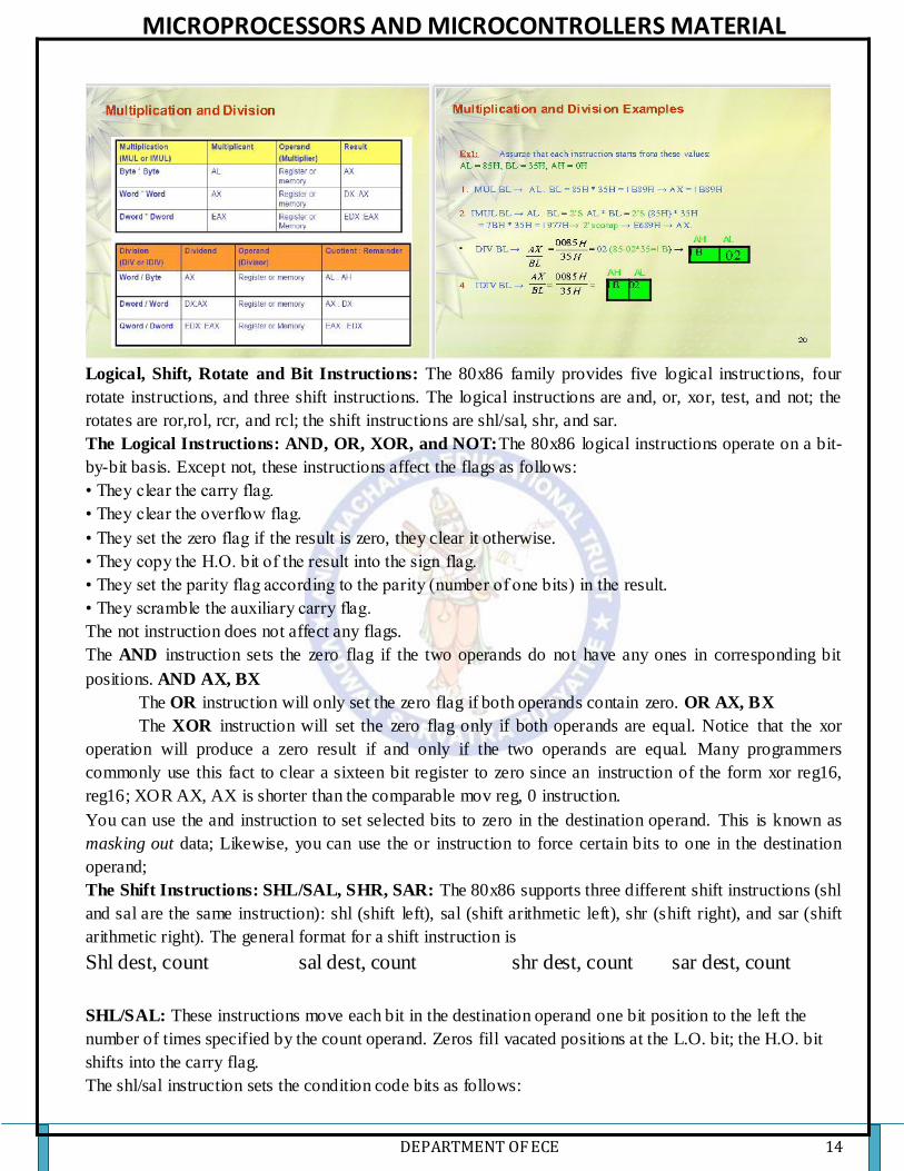
The Multiplication Instructions: MUL, IMUL, and AAM: This instruction multiplies an unsigned byte
or word by the contents of AL. The unsigned byte or word may be in any one of the general-purpose
registers or memory locations. The most significant word of the result is stored in DX, while the least
significant word of the result is stored in AX.
The mul instruction, with an eight bit operand, multiplies the al register by the operand and stores the
16 bit result in ax. So
mul operand (Unsigned) MUL BL i.e. AL * BL; Al=25 * BL=04; AX=00 (AH) 64 (AL)
imul operand (Signed) IMUL BL i.e. AL * BL; AL=09 * BL=-2; AL * 2’s comp(BL)
AL=09 * BL (0EH) =7E; 2’s comp (7e) =-82
The aam (ASCII Adjust after Multiplication) instruction, adjust an unpacked decimal value after
multiplication. This instruction operates directly on the ax register. It assumes that you’ve multiplied two
eight bit values in the range 0..9 together and the result is sitting in ax (actually, the result will be sitting
in al since 9*9 is 81,the largest possible value; ah must contain zero). This instruction divides ax by 10
and leaves the quotient in ah and the remainder in al: mul bl; al=9, bl=9 al*bl=9*9=51H; AX=00(AH)
51(AL); AAM ; first hexadecimal value is converted to decimal value i.e. 51 to 81; al=81D; second
convert packed BCD to unpacked BCD, divide AL content by 10 i.e. 81/10 then AL=01, AH =08; AX =
0801
EXAMPLE:
AL 00000101 unpacked BCD 5
BH 00001001 unpacked BCD 9
MUL BH AL x BH; result in AX
AX = 00000000 00101101 = 002DH
AAM AX = 00000100 00000101 = 0405H, which is unpacked BCD for 45.
If ASCII codes for the result are desired, use next instruction OR AX, 3030H Put 3 in upper nibble of
each byte.
AX = 0011 0100 0011 0101 = 3435H, which is ASCII code for 45

MICROPROCESSORS AND MICROCONTROLLERS MATERIAL
DEPARTMENT OF ECE 13
The Division Instructions: DIV, IDIV, and AAD
The 80x86 divide instructions perform a 64/32 division (80386 and later only), a 32/16division or a 16/8
division. These instructions take the form:
Div reg For unsigned division
Div mem
Idiv reg For signed division
Idiv mem
The div instruction computes an unsigned division. If the operand is an eight bit operand, div divides the
ax register by the operand leaving the quotient in al and the remainder (modulo) in ah. If the operand is a
16 bit quantity, then the div instruction divides the 32 bit quantity in dx:ax by the operand leaving the
quotient in ax and the remainder in .
Note: If an overflow occurs (or you attempt a division by zero) then the80x86 executes an INT 0
(interrupt zero).
The aad (ASCII Adjust before Division) instruction is another unpacked decimal operation.It splits apart
unpacked binary coded decimal values before an ASCII division operation. The aad instruction is useful
forother operations. The algorithm that describes this instruction is
al := ah*10 + al AX=0905H; BL=06; AAD; AX=AH*10+AL=09*10+05=95D;
convert decimal to hexadecimal; 95D=5FH; al=5f;
DIV BL; AL/BL=5F/06; AX=05(AH) 0F (AL)
ah := 0
EXAMPLE:
AX = 0607H unpacked BCD for 67 decimal CH = 09H, now adjust to binary
AAD Result: AX = 0043 = 43H = 67 decimal
DIV CH Divide AX by unpacked BCD in CH
Quotient: AL = 07 unpacked BCD Remainder:
AH = 04 unpacked BCD Flags undefined after DIV
NOTE: If an attempt is made to divide by 0, the 8086 will do a type 0 interrupt.
CBW-Convert Signed Byte to Signed Word: This instruction copies the sign of a byte in AL to all the
bits in AH. AH is then said to be the sign extension of AL. The CBW operation must be done beforea
signed byte in AL can be divided by another signed byte with the IDIV instruction. CBW affects no flags.
EXAMPLE:
AX = 00000000 10011011 155 decimal
CBW Convert signed byte in AL to signed word in AX
Result: AX = 11111111 10011011 155 decimal
CWD-Convert Signed Word to Signed Double word: CWD copies the sign bit of a word in AX to all
the bits of the DX register. In other words it extends the sign of AX into all of DX. The CWD operation
must be done before a signed word in AX can be divided by another signed word with the IDIV
instruction. CWD affects no flags.
EXAMPLE:
DX = 00000000 00000000
AX = 11110000 11000111 3897 decimal
CWD Convert signed word in AX to signed doubleword in DX:AX
Result DX = 11111111 11111111
AX = 11110000 11000111 3897 decimal
MICROPROCESSORS AND MICROCONTROLLERS MATERIAL
DEPARTMENT OF ECE 14
Logical, Shift, Rotate and Bit Instructions: The 80x86 family provides five logical instructions, four
rotate instructions, and three shift instructions. The logical instructions are and, or, xor, test, and not; the
rotates are ror,rol, rcr, and rcl; the shift instructions are shl/sal, shr, and sar.
The Logical Instructions: AND, OR, XOR, and NOT:The 80x86 logical instructions operate on a bit-
by-bit basis. Except not, these instructions affect the flags as follows:
• They clear the carry flag.
• They clear the overflow flag.
• They set the zero flag if the result is zero, they clear it otherwise.
• They copy the H.O. bit of the result into the sign flag.
• They set the parity flag according to the parity (number of one bits) in the result.
• They scramble the auxiliary carry flag.
The not instruction does not affect any flags.
The AND instruction sets the zero flag if the two operands do not have any ones in corresponding bit
positions. AND AX, BX
The OR instruction will only set the zero flag if both operands contain zero. OR AX, BX
The XOR instruction will set the zero flag only if both operands are equal. Notice that the xor
operation will produce a zero result if and only if the two operands are equal. Many programmers
commonly use this fact to clear a sixteen bit register to zero since an instruction of the form xor reg16,
reg16; XOR AX, AX is shorter than the comparable mov reg, 0 instruction.
You can use the and instruction to set selected bits to zero in the destination operand. This is known as
masking out data; Likewise, you can use the or instruction to force certain bits to one in the destination
operand;
The Shift Instructions: SHL/SAL, SHR, SAR: The 80x86 supports three different shift instructions (shl
and sal are the same instruction): shl (shift left), sal (shift arithmetic left), shr (shift right), and sar (shift
arithmetic right). The general format for a shift instruction is
Shl dest, count sal dest, count shr dest, count sar dest, count
SHL/SAL: These instructions move each bit in the destination operand one bit position to the left the
number of times specified by the count operand. Zeros fill vacated positions at the L.O. bit; the H.O. bit
shifts into the carry flag.
The shl/sal instruction sets the condition code bits as follows:

MICROPROCESSORS AND MICROCONTROLLERS MATERIAL
DEPARTMENT OF ECE 15
• If the shift count is zero, the shl instruction doesn’t affect any flags.
• The carry flag contains the last bit shifted out of the H.O. bit of the operand.
• The overflow flag will contain one if the two H.O. bits were different prior to a single bit shift. The
overflow flag is undefined if the shift count is not one.
• The zero flag will be one if the shift produces a zero result.
• The sign flag will contain the H.O. bit of the result.
• The parity flag will contain one if there are an even number of one bits in the L.O. byte of the result.
• The A flag is always undefined after the shl/sal instruction.
The shift left instruction is especially useful for packing data. For example, suppose you have two
nibbles in al and ah that you want to combine. You could use the following code to do this:
shl ah, 4 ;
or al, ah ; Merge in H.O. four bits.
Of course, al must contain a value in the range 0..F for this code to work properly (the shift left operation
automatically clears the L.O. four bits of ah before the or instruction).
SHL OPERATION
H.O. four bits of al are not zero before this operation, you can easily clear them with an and instruction:
shl ah, 4 ;Move L.O. bits to H.O. position.
and al, 0Fh ;Clear H.O. four bits.
or al, ah ;Merge the bits.
Since shifting an integer value to the left one position is equivalent to multiplying that value by two, you
can also use the shift left instruction for multiplication by powers of two:
shl ax, 1 ;Equivalent to AX*2
shl ax, 2 ;Equivalent to AX*4
shl ax, 3 ;Equivalent to AX*8
SAR:Thesar instruction shifts all the bits in the destination operand to the right one bit, replicating the
H.O. bit.
The sar instruction’s main purpose is to perform a signed division by some power of two. Each shift to the
right divides the value by two. Multiple right shifts divide the previous shifted result by two, so multiple
shifts produce the following results:
SAR OPERATION
sar ax, 1 ;Signed division by 2
sar ax, 2 ;Signed division by 4
sar ax, 3 ;Signed division by 8
sar ax, 4 ;Signed division by 16
sar ax, 5 ;Signed division by 32
sar ax, 6 ;Signed division by 64
sar ax, 7 ;Signed division by 128
sar ax, 8 ;Signed division by 256

MICROPROCESSORS AND MICROCONTROLLERS MATERIAL
DEPARTMENT OF ECE 16
There is a very important difference between the sar and idiv instructions. The idiv instruction always
truncates towards zero while sar truncates results toward the smaller result. For positive results, an
arithmetic shift right by one position produces the same result as an integer division by two. However, if
the quotient is negative, idiv truncates towards zero while sar truncates towards negative infinity.
SHR: The shr instruction shifts all the bits in the destination operand to the right one bit shifting a zero
into the H.O. bit
SHR OPERATION
The shift right instruction is especially useful for unpacking data. shifting an unsigned integer value to the
right one position is equivalent to dividing that value by two, you can also use the shift right instruction
for division by powers of two:
shr ax, 1 ;Equivalent to AX/2
shr ax, 2 ;Equivalent to AX/4
shr ax, 3 ;Equivalent to AX/8
shr ax, 4 ;Equivalent to AX/16
The Rotate Instructions: RCL, RCR, ROL, and ROR
The rotate instructions shift the bits around, just like the shift instructions, except the bits shifted out of the operand by the rotate
instructions recirculate through the operand. They include rcl (rotate through carry left), rcr(rotate through carry right), rol(rotate left),
And ror (rotate right). These instructions all take the forms: rcl dest, count rol dest, count rcr dest, count ror dest, count
RCL: The rcl (rotate through carry left), as its name implies, rotates bits to the left, through the carry flag, and back into bit zero on
the right. The rcl instruction sets the flag bits as follows: • The carry flag contains the last bit shifted out of the H.O. bit of the operand.
• If the shift count is one, rcl sets the overflow flag if the sign changes as a result of the rotate. If the count is not one, the overflow
flag is undefined.
• The rcl instruction does not modify the zero, sign, parity, or auxiliary carry flags.
RCL OPERATION
RCR: The rcr (rotate through carry right) instruction is the complement to the rcl instruction. It shifts its
bits right through the carry flag and back into the H.O. bit. This instruction sets the flags in a manner
analogous to rcl:
• The carry flag contains the last bit shifted out of the L.O. bit of the operand.
• The rcr instruction does not affect the zero, sign, parity, or auxiliary carry flags.
RCR OPERATION
ROL: The rol instruction is similar to the rcl instruction in that it rotates its operand to the left the
specified number of bits. The major difference is that rol shifts its operand’s H.O. bit, rather than the
carry, into bit zero. Rol also copies the output of the H.O. bit into the carry flag. The rol instruction sets
the flags identically to rcl. Other than the source of the value shifted into bit zero, this instruction behaves
exactly like the rcl instruction.
Like shl, the rol instruction is often useful for packing and unpacking data.
MICROPROCESSORS AND MICROCONTROLLERS MATERIAL
DEPARTMENT OF ECE 17
ROL OPERATION
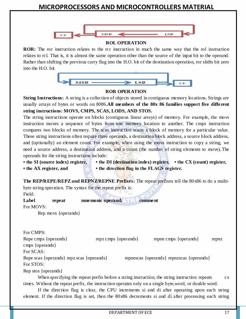
ROR: The ror instruction relates to the rcr instruction in much the same way that the rol instruction
relates to rcl. That is, it is almost the same operation other than the source of the input bit to the operand.
Rather than shifting the previous carry flag into the H.O. bit of the destination operation, ror shifts bit zero
into the H.O. bit.
ROR OPERATION
String Instructions: A string is a collection of objects stored in contiguous memory locations. Strings are
usually arrays of bytes or words on 8086.All members of the 80x 86 families support five different
string instructions: MOVS, CMPS, SCAS, LODS, AND STOS.
The string instructions operate on blocks (contiguous linear arrays) of memory. For example, the movs
instruction moves a sequence of bytes from one memory location to another. The cmps instruction
compares two blocks of memory. The scas instruction scans a block of memory for a particular value.
These string instructions often require three operands, a destination block address, a source block address,
and (optionally) an element count. For example, when using the movs instruction to copy a string, we
need a source address, a destination address, and a count (the number of string elements to move). The
operands for the string instructions include:
• the SI (source index) register, • the DI (destination index) register, • the CX (count) register,
• the AX register, and • the direction flag in the FLAGS register.
The REP/REPE/REPZ and REPNZ/REPNE Prefixes: The repeat prefixes tell the 80x86 to do a multi-
byte string operation. The syntax for the repeat prefix is:
Field:
Label repeat mnemonic operand; comment
For MOVS:
Rep movs {operands}
For CMPS:
Repe cmps {operands} repz cmps {operands} repne cmps {operands} repnz
cmps {operands}
For SCAS:
Repe scas {operands} repz scas {operands} repnescas {operands} repnzscas {operands}
For STOS:
Rep stos {operands}
When specifying the repeat prefix before a string instruction, the string instruction repeats cx
times. Without the repeat prefix, the instruction operates only on a single byte,word, or double word.
If the direction flag is clear, the CPU increments si and di after operating upon each string
element. If the direction flag is set, then the 80x86 decrements si and di after processing each string

MICROPROCESSORS AND MICROCONTROLLERS MATERIAL
DEPARTMENT OF ECE 18
element. The direction flag may be set or cleared using the cld (clear direction flag) and std (setdirection
flag) instructions.
The MOVS Instruction: The movsb (move string, bytes) instruction fetches the byte at address ds:si,
stores it at address es :di, and then increments or decrements the si and di registers by one. If the rep
prefix is present, the CPU checks cx to see if it contains zero. If not, then it moves the byte from ds: si to
es: di and decrements the cx register. This process repeats until cx becomes zero. The syntax is:
{REP} MOVSB {REP} MOVSW
The CMPS Instruction: The cmps instruction compares two strings. The CPU compares the string
referenced by es: di to the string pointed at by ds: si. CX contains the length of the two strings (when
using the rep prefix). The syntax is: {REPE} CMPSB {REPE} CMPSW
To compare two strings to see if they are equal or not equal, you must compare corresponding
elements in a string until they don’t match or length of the string cx=0.The repe prefix accomplishes
this operation. It will compare successive elements in a string as long as they are equal and cx is greater
than zero.
The SCAS Instruction: The scas instruction, by itself, compares the value in the accumulator (al or ax)
against the value pointed at by es:di and then increments (or decrements) di by one or two. The CPU sets
the flags according to the result of the comparison. When using the repne prefix (repeat while not equal),
scas scans the string searching for the first string element which is equal to the value in the accumulator.
The scas instruction takes the following forms: {REPNE} SCASB {REPNE} SCASW
The STOS Instruction: The stos instruction stores the value in the accumulator at the location specified
by es: di. After storing the value, the CPU increments or decrements di depending upon the state of the
direction flag. Its primary use is to initialize arrays and strings to a constant value. {REP} STOSB
{REP} STOSW
The LODS Instruction: The lods instruction copies the byte or word pointed at by ds:si into the al or ax
register, after which it increments or decrements the si register by one or two.{REP} LODSB
{REP} LODSW
Flag Manipulation and Processor Control Instructions: These instructions control the functioning of
the available hardware inside the processor chip. These are categorized into two types; (a) flag
manipulation instructions and (b) machine control instructions.
The flag manipulation instructions directly modify some of the flags of 8086. The machine control
instructions control the bus usage and execution. The flag manipulation instructions and their functions
are as follows:
CLC - Clear carry flag CMC - Complement carry flag STC - Set carry flag
CLD - Clear direction flag STD - Set direction flag CLI - Clear interrupt flag
STI - Set interrupt flag
These instructions modify the carry (CF), direction (DF) and interrupt (IF) flags directly. The DF and IF,
which may be modified using the flag manipulation instructions, further control the processor operation;
like interrupt responses and auto increment or auto decrement modes.
The machine control instructions supported by 8086 and 8088 are listed as follows along with
their functions. These machine control instructions do not require any operand.
WAIT - Wait for Test input pin to go low HLT - Halt the processor NOP - No
operation ESC - Escape to external device like NDP (numeric co-processor) LOCK - Bus
lock instruction prefix.

MICROPROCESSORS AND MICROCONTROLLERS MATERIAL
DEPARTMENT OF ECE 19
After executing the HLT instruction, the processor enters the halt state. The two ways to pull it out of the
halt state are to reset the processor or to interrupt it.
When NOP instruction is executed, the processor does not perform any operation till 4 clock
cycles, except incrementing the IP byone. It then continues with further execution after 4 clock cycles.
ESC instruction when executed, frees the bus for an external master like a coprocessor or
peripheral devices.
The LOCK prefix may appear with another instruction. When it is executed, the bus access is not
allowed for another master till the lock prefixed instruction is executed completely. This instruction is
used in case of programming for multiprocessor systems.
The WAIT instruction when executed holds the operation of processor with the current status till
the logic level on the TEST pin goes low. The processor goes on inserting WAIT states in the instruction
cycle, till the TEST pin goes low. Once the TEST pin goes low, it continues further execution.
Program Flow Control Instructions: The control transfer instructions are used to transfer the control
from one memory location to another memory location. In 8086 program control instructions belong to
three groups: unconditional transfers, conditional transfers, and subroutine call and return instructions.
Unconditional Jumps: The jmp (jump) instruction unconditionally transfers control to another point in
the program. Intra segment jumps are always between statements in the same code segment. Intersegment
jumps can transfer control to a statement in a different code segment.
JMP Address
Unconditional jump Conditional jump
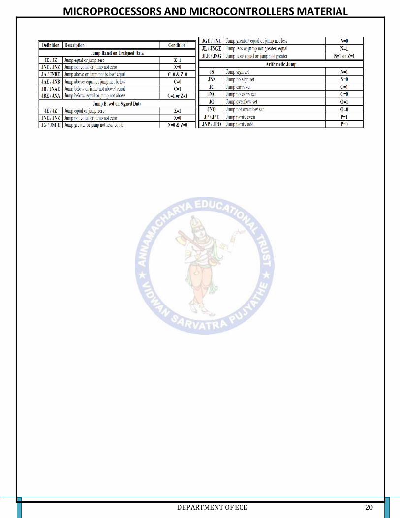
Conditional Jump: The conditional jump instructions are the basic tool for creating loops and other
conditionally executable statements like the if…..then statement. The conditional jumps test one or more
bits in the status register to see if they match some particular pattern. If the pattern matches, control
transfers to the target location. If the condition fails, the CPU ignores the conditional jump and execution
continues with the next instruction. Some instructions, for example, test the conditio ns of the sign, carry,
overflow and zero flags.
MICROPROCESSORS AND MICROCONTROLLERS MATERIAL
DEPARTMENT OF ECE 20

MICROPROCESSORS AND MICROCONTROLLERS MATERIAL
DEPARTMENT OF ECE 21
Loop Instruction:
• These instructions are used to repeat a set of instructions several times.
• Format: LOOP Short-Label
• Operation: (CX) (CX)-1
• Jump is initialized to location defined by short label if CX≠0. Otherwise, execute next
sequential instruction.
• Instruction LOOP works with respect to contents of CX. CX must be preloaded with a count
that represents the number of times the loop is to be repeat.
• Whenever the loop is executed, contents at CX are first decremented then checked to
determine if they are equal to zero.
• If CX=0, loop is complete and the instruction following loop is executed.
• If CX ≠ 0, content return to the instruction at the label specified in the loop instruction.
• LOOP AGAIN is almost same as: DEC CX, JNZ AGAIN
SUBROUTINE & SUBROUTINE HANDILING INSTRUCTIONS: CALL, RET
A subroutine is a special segment of program that can be called for execution from any point in
a program.
An assembly language subroutine is also referred to as a “procedure”.
Whenever we need the subroutine, a single instruction is inserted in to the main body of the
program to call subroutine.
Transfers the flow of the program to the procedure.
CALL instruction differs from the jump instruction because a CALL saves a return address on
the stack.
The return address returns control to the instruction that immediately follows the
CALL in a program when a RET instruction executes.
To branch a subroutine the value in the IP or CS and IP must be modified.
After execution, we want to return the control to the instruction that immediately follows the
one called the subroutine i.e., the original value of IP or CS and IP must be preserved.
Execution of the instruction causes the contents of IP to be saved on the stack. (this time (SP)
(SP) -2 )
A new 16-bit (near-proc, mem16, reg16 i.e., Intra Segment) value which is specified by the
instructions operand is loaded into IP.
Examples: CALL 1234H
CALL BX
CALL [BX]
Return Instruction: RET instruction removes an address from the stack so the program returns to the
instruction following the CALL
• Every subroutine must end by executing an instruction that returns control to the main
program. This is the return (RET) instruction.

MICROPROCESSORS AND MICROCONTROLLERS MATERIAL
DEPARTMENT OF ECE 22
• By execution the value of IP or IP and CS that were saved in the stack to be returned back to
their corresponding registers. (this time (SP) (SP)+2 )
MACROS: The macro directive allows the programmer to write a named block of source statements,
then use that name in the source file to represent the group of statements. During the assembly phase,
the assembler automatically replaces each occurrence of the macro name with the statements in the
macro definition.
Macros are expanded on every occurrence of the macro name, so they can increase the length
of the executable file if used repeatably. Procedures or subroutines take up less space, but the
increased overhead of saving and restoring addresses and parameters can make them slower. In
summary, the advantages and disadvantages of macros are,
Advantages
Repeated small groups of instructions replaced by one macro
Errors in macros are fixed only once, in the definition
Duplication of effort is reduced
In effect, new higher level instructions can be created
Programming is made easier, less error prone
Generally quicker in execution than subroutines
Disadvantages
In large programs, produce greater code size than procedures
When to use Macros
To replace small groups of instructions not worthy of subroutines
To create a higher instruction set for specific applications
To create compatibility with other computers
To replace code portions which are repeated often throughout the program
Modular Programming: Instead of writing a large program in a single unit, it is better to write
small programs—which are parts of the large program. Such small programs are called program
modules or simply modules. Each such module can be separately written, tested and debugged. Once
the debugging of the small programs is over, they can be linked together. Such methodology of
developing a large program by linking the modules is called modular programming.
Assembler Directives:
Assembler directives are special instructions that provide information to the assembler but do not
generate any code. Examples include the segment directive, equ, assume and end. These mnemonics
are not valid 80x86 instructions. They are messages to the assembler, to generate address.
A pseudo-opcode is a message to the assembler, just like an assembler directive, however a
pseudo-opcode will emit object code bytes. Examples of pseudo-opcodes include byte, word, dword,
qword, and byte. These instructions emit the bytes of data specified by their operands but they are not
true 80X86 machine instructions.
ASSUME: The ASSUME directive tell the assembler the name of the logical segment it should use
for a specified segment. Ex: ASSUME CS: Code, DS: Data, SS: Stack; or ASSUME CS: Code
Data Directives: The directives DB, DW, DD, DR and DT are used to (a) define different types of
variables or (b) to set aside one or more storage locations in memory-depending on the data type:
DB — Define Byte DW — Define Word DD — Define Double word
DQ — Define Quad word DT — Define Ten Bytes
The DB directive is used to declare a byte-type variable or to set aside one or more storage locations
of type byte in memory (Define Byte)

MICROPROCESSORS AND MICROCONTROLLERS MATERIAL
DEPARTMENT OF ECE 23
Example: Temp DB 42H; Temp is a variable allotted 1byte of memory location assigned with data
42H
The DW directive is used to declare a variable of type word or to reserve memory locations which can
be accessed as type double word (Define word)
Example: N2 DW 427AH; N2 variable is initialized with value 427AH when it is loaded into memory
to run.
The DD directive is used to declare a variable of type double word or to reserve memory locations
which can be accessed as type double word (Define double word)
Example: Big DD 2456756CH; Big variable is initialized with 4 bytes
The DQ directive is used to tell the assembler to declare a variable 4 words in length or to reverse 4
words of storage in memory (Define Quad word)
Example: Big DQ 2456756C88464567H; Big variable is initialized with 4 words (8 bytes)
The DT directive is used to tell the assembler to declare a variable 10 bytes in length or to reverse
10bytes of storage in memory (Define Ten bytes)
Example: Packed BCD DT 11223344556677889900H; 10 byte data is initialized to variable packed
BCD
DUP: This directive operator is used to initialize several locations and to assign values to these
locations. Its format is: Name Data-Type Num DUP (value)
Example: TABLE DB 20 DUP (0); Reserve an array of 20 bytes of memory and initialize all 20 bytes
with 0. Array is named TABLE
END: The END directive is placed after the last statement of a program to tell the assembler that this
is the end of the program module. The assembler will ignore any statement after an end directive.
The ENDP directive is used with the name of the procedure to indicate the end of a procedure to the
assembler.
SQUARE NUM PROC
….
….
SQUARE NUM ENDP
The ENDS directive is used with the name of the segment to indicate the end of a segment to the
assembler.
CODE SEGMENT
…
…
CODE ENDS
EQU: The EQU directive is used to give a name to some value or to a symbol. Each time assembler
finds the name in the program it will replace the name with the value.
FACTOR EQU 03H; This statement should be written at the start
ADD AL, FACTOR; The assembler converts this instruction as ADD AL, 03H
EVEN: The EVEN directive instructs the assembler to increment the location of the counter to the
next even address if it is not already in the even address. If the word starts at an odd address, 8086 will
take 2 bus cycles to get the 2 byte of the word. “A series of words can read much more quickly if they
are at even address”.
DATA HERE SEGMENT ; Location counter will point to 0009H after assembler reads next
statement
SALES DB 9 DUP (?) ; Declare an array of 9 bytes
EVEN ; Increment location counter to 000AH
RECORD DW 100 DUP (?) ; Array of 100 words starting on even address for quicker read
DATA HERE ENDS ;

MICROPROCESSORS AND MICROCONTROLLERS MATERIAL
DEPARTMENT OF ECE 24
GLOBAL: This GLOBAL directive can be used in place of PUBLIC directive or in place of an
EXTRN directive. The GOLBAL directive is used to make the symbol available to other modules.
PUBLIC: The PUBLIC directive is used along with the EXTRN directive. This informs the
assembler that the labels, variables, constants, or procedures declared PUBLIC may be accessed by
other assembly modules to form their codes, but while using the PUBLIC declared labels, variables,
constants or procedures the user must declare them externals using the EXTRN directive.
EXTRN: This EXTRN directive is used to tell the assembler that the names or labels following the
directive are in some other assembly module.
GROUP: This GROUP directive is used to tell the assembler to group the logical segments named
after the directive into one logical group segment.
Example: SMALL SYSTEM GROUP CODE, DATA, STACK
ASSUME CS: SMALL SYSTEM, DS: SMALL SYSTEM, SS: SMALL SYSTEM
OFFSET—Is an operator which tells the assembler to determine the offset or the displacement of a
named data item (variable) or procedure from start of the segment which contains it. This operator is
used to load the offset of a variable into a register so that the variable can be accessed with one of the
indexed addressing modes. MOV AL, OFFSET N1
ORG – This ORG directive allows to set the location counter to a desired value at any point in the
program. The statement ORG 100H tells the assembler to set the location counter to 0100H.
PROCEDURE: A PROC directive is used to define a label and to delineate a sequence of instructions
that are usually interpreted to be a subroutine, that is, CALLed either from within the same physical
segment (near) or from another physical segment (far).
Syntax:
name PROC [type] P1 PROC NEAR
MOV AX, 1 5
ADD OX, AX
….. ENDP
name ENDP
Labels: A label, a symbolic name for a particular location in an instruction sequence, maybe defined
in one of three ways. The first way is the most common. The format is shown below: label:
[instruction]
where "label" is a unique ASM86 identifier and "instruction" is an8086/8087/8088 instruction. This
label will have the following attributes:
1. Segment-the current segment being assembled.
2. Offset-the current value of the location counter.
3. Type-will be NEAR.
An example of this form of label definition is: ALAB: MOV AX, COUNT
PROGRAM: 8 – BIT ADDITION
LABEL MNEMONICS COMMENTS
ASSUME CS:CODE,
DS:DATA
DATA SEGMENT ORG 3000H N1 DB 00H
N2 DB 00H

MICROPROCESSORS AND MICROCONTROLLERS MATERIAL
DEPARTMENT OF ECE 25
RES DB 00H
DATA ENDS
CODE SEGMENT ORG 4000H
START: MOV AX, DATA Initialize the data
segment
MOV DS, AX
MOV AX, 0000 Clear the accumulator
MOV AL, N1 Copy the content of data from N1 memory
location
MOV BL, N2 Copy the content of data from N2 memory
location
ADD AL, BL Perform addition on AL and BL registers
and store result in AL
MOV RES, AL Copy the content of accumulator to RES memory location
INT 03H Return control to OS
CODE ENDS
END START
OBSERVATIONS:
INPUT OUTPUT
MEMORY LOCATION
DATA
VALUE
MEMORY LOCATION
DATA
VALUE
3000
3001
25
34
3002
59
PROGRAM: 8 – BIT SUBTRACTION
LABEL MNEMONICS COMMENTS
ASSUME CS:CODE, DS:DATA
DATA SEGMENT ORG 3000H N1 DB 00H
N2 DB 00H RES DB 00H
DATA ENDS
CODE SEGMENT ORG 4000H
START: MOV AX, DATA Initialize the data segment
MOV DS, AX
MOV AX, 0000 Clear the accumulator
MOV AL, N1 Copy the content of data from N1 memory location
MOV BL, N2 Copy the content of
MICROPROCESSORS AND MICROCONTROLLERS MATERIAL
DEPARTMENT OF ECE 26
data from N2 memory
location
SUB AL, BL Perform subtraction on AL and BL
registers and store result in AL
MOV RES, AL Copy the content of
accumulator to RES memory location
INT 03H Return control to OS
CODE ENDS
END START
OBSERVATIONS:
INPUT OUTPUT
MEMORY LOCATION
DATA
VALUE
MEMORY LOCATION
DATA
VALUE
3000
3001
35
14
3002
21
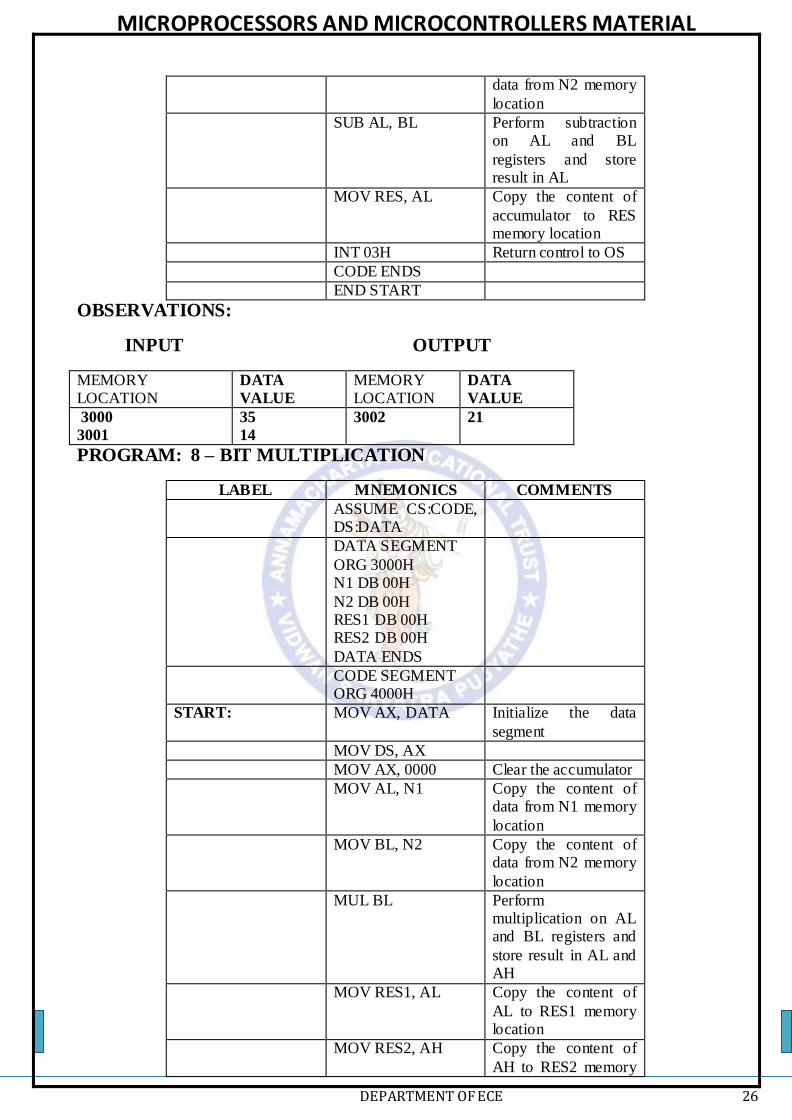
PROGRAM: 8 – BIT MULTIPLICATION
LABEL MNEMONICS COMMENTS
ASSUME CS:CODE, DS:DATA
DATA SEGMENT
ORG 3000H N1 DB 00H
N2 DB 00H RES1 DB 00H RES2 DB 00H
DATA ENDS
CODE SEGMENT ORG 4000H
START: MOV AX, DATA Initialize the data
segment
MOV DS, AX
MOV AX, 0000 Clear the accumulator
MOV AL, N1 Copy the content of data from N1 memory
location
MOV BL, N2 Copy the content of data from N2 memory
location
MUL BL Perform multiplication on AL and BL registers and
store result in AL and AH
MOV RES1, AL Copy the content of
AL to RES1 memory location
MOV RES2, AH Copy the content of
AH to RES2 memory

MICROPROCESSORS AND MICROCONTROLLERS MATERIAL
DEPARTMENT OF ECE 27
location
INT 03H Return control to OS
CODE ENDS
END START
OBSERVATIONS:
INPUT OUTPUT
MEMORY LOCATION
DATA
VALUE
MEMORY LOCATION
DATA
VALUE
3000
3001
98
C5
3002
3003
F8
74
PROGRAM: 8 – BIT DIVISION
LABEL MNEMONICS COMMENTS
ASSUME CS:CODE, DS:DATA
DATA SEGMENT ORG 3000H N1 DB 00H
N2 DB 00H RES1 DB 00H RES2 DB 00H
DATA ENDS
CODE SEGMENT ORG 4000H
START: MOV AX, DATA Initialize the data
segment
MOV DS, AX
MOV AX, 0000 Clear the accumulator
MOV AL, N1 Copy the content of data from N1 memory
location
MOV BL, N2 Copy the content of data from N2 memory
location
DIV BL Perform division on AL and BL registers
and store quotient in AL and remainder in AH
MOV RES1, AL Copy the content of
AL to RES1 memory location
MOV RES2, AH Copy the content of
AH to RES2 memory

MICROPROCESSORS AND MICROCONTROLLERS MATERIAL
DEPARTMENT OF ECE 28
location
INT 03H Return control to OS
CODE ENDS
END START
OBSERVATIONS:
INPUT OUTPUT
MEMORY LOCATION
DATA
VALUE
MEMORY LOCATION
DATA
VALUE
3000
3001
98
15
3002
3003
07
05
PROGRAM: 16 – BIT ADDITION
LABEL MNEMONICS COMMENTS
ASSUME CS:CODE, DS:DATA
DATA SEGMENT ORG 3000H
N1 DW 00H N2 DW 00H
RES1 DW 00H RES2 DW 00H DATA ENDS
CODE SEGMENT ORG 4000H
START: MOV AX, DATA Initialize the data segment
MOV DS, AX
MOV AX, 0000 Clear the accumulator
MOV CX, 0000 Clear CX register
MOV AX, N1 Copy the content of data from N1 memory location
MOV BX, N2 Copy the content of data from N2 memory location
ADD AX, BX Perform addition on
AX and BX registers and store result in AX
JNC L1 Jump if CF is not zero
to L1

MICROPROCESSORS AND MICROCONTROLLERS MATERIAL
DEPARTMENT OF ECE 29
INC CX Increment count
L1: MOV RES1, AX Copy the content of AX to RES1 memory location
MOV RES2, CX Copy the content of
AX to RES2 memory location
INT 03H Return control to OS
CODE ENDS
END START
OBSERVATIONS:
WITH CARRY
INPUT OUTPUT
MEMORY LOCATION
DATA
VALUE
MEMORY LOCATION
DATA
VALUE
3000
3001
3002
3003
98
C5
78
5D
3004
3005
3006
3007
10
23
00
01
WITH OUT CARRY
MEMORY LOCATION
DATA
VALUE
MEMORY LOCATION
DATA
VALUE
3000
3001
3002
3003
98
C5
A6
12
3004
3005
3006
3007
3E
D8
00
00
PROGRAM: 16 – BIT SUBTRACTION
LABEL MNEMONICS COMMENTS
ASSUME CS:CODE, DS:DATA
DATA SEGMENT
ORG 3000H N1 DW 00H N2 DW 00H
RES1 DW 00H RES2 DW 00H
DATA ENDS
CODE SEGMENT ORG 4000H
START: MOV AX, DATA Initialize the data
segment
MOV DS, AX
MOV AX, 0000 Clear the accumulator
MOV CX, 0000 Clear CX register
MOV AX, N1 Copy the content of data from N1 memory
location

MICROPROCESSORS AND MICROCONTROLLERS MATERIAL
DEPARTMENT OF ECE 30
MOV BX, N2 Copy the content of
data from N2 memory location
SUB AX, BX Perform subtraction
on AX and BX registers and store
result in AX
JNC L1 Jump if CF is not zero to L1
INC CX Increment count
L1: MOV RES1, AX Copy the content of
AX to RES1 memory location
MOV RES2, CX Copy the content of AX to RES2 memory
location
INT 03H Return control to OS
CODE ENDS
END START
OBSERVATIONS:
WITH BORROW
INPUT OUTPUT
MEMORY LOCATION
DATA
VALUE
MEMORY LOCATION
DATA
VALUE
3000
3001
3002
3003
98
C5
78
DD
3004
3005
3006
3007
20
E8
00
01
WITH OUT BORROW
MEMORY
LOCATION
DATA
VALUE
MEMORY
LOCATION
DATA
VALUE
3000
3001
3002
3003
98
C5
78
5D
3004
3005
3006
3007
20
68
00
00
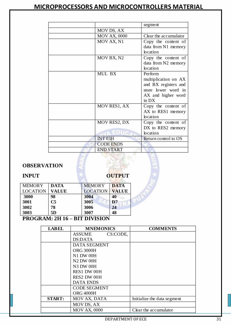
PROGRAM: 16 – BIT MULTIPLICATION
LABEL MNEMONICS COMMENTS
ASSUME CS:CODE, DS:DATA
DATA SEGMENT ORG 3000H
N1 DW 00H N2 DW 00H
RES1 DW 00H RES2 DW 00H DATA ENDS
CODE SEGMENT
ORG 4000H
START: MOV AX, DATA Initialize the data
MICROPROCESSORS AND MICROCONTROLLERS MATERIAL
DEPARTMENT OF ECE 31
segment
MOV DS, AX
MOV AX, 0000 Clear the accumulator
MOV AX, N1 Copy the content of data from N1 memory location
MOV BX, N2 Copy the content of data from N2 memory location
MUL BX Perform
multiplication on AX and BX registers and
store lower word in AX and higher word in DX
MOV RES1, AX Copy the content of
AX to RES1 memory location
MOV RES2, DX Copy the content of
DX to RES2 memory location
INT 03H Return control to OS
CODE ENDS
END START
OBSERVATION
INPUT OUTPUT
MEMORY
LOCATION
DATA
VALUE
MEMORY
LOCATION
DATA
VALUE
3000
3001
3002
3003
98
C5
78
5D
3004
3005
3006
3007
40
D7
24
48
PROGRAM: 2H 16 – BIT DIVISION
LABEL MNEMONICS COMMENTS
ASSUME CS:CODE, DS:DATA
DATA SEGMENT
ORG 3000H N1 DW 00H N2 DW 00H
N3 DW 00H RES1 DW 00H
RES2 DW 00H DATA ENDS
CODE SEGMENT ORG 4000H
START: MOV AX, DATA Initialize the data segment
MOV DS, AX
MOV AX, 0000 Clear the accumulator

MICROPROCESSORS AND MICROCONTROLLERS MATERIAL
DEPARTMENT OF ECE 32
MOV AX, N1 Copy the content of data from
N1 memory location to AX
MOV DX, N2 Copy the content of data from N2 memory location to DX
MOV BX, N3 Copy the content of data from
N3 memory location to BX
DIV BX Perform division on AX DX by BX registers and store quotient
in AX and remainder in DX
MOV RES1, AX Copy the content of AX to RES1 memory location
MOV RES2, DX Copy the content of DX to
RES2 memory location
INT 03H Return control to OS
CODE ENDS
END START
OBSERVATION
INPUT OUTPUT
MEMORY
LOCATION
DATA
VALUE
MEMORY
LOCATION
DATA
VALUE
3000
3001
3002
3003
3004
3005
98
C5
78
5D
78
98
3006
3007
3008
3009
F1
9C
A0
1C
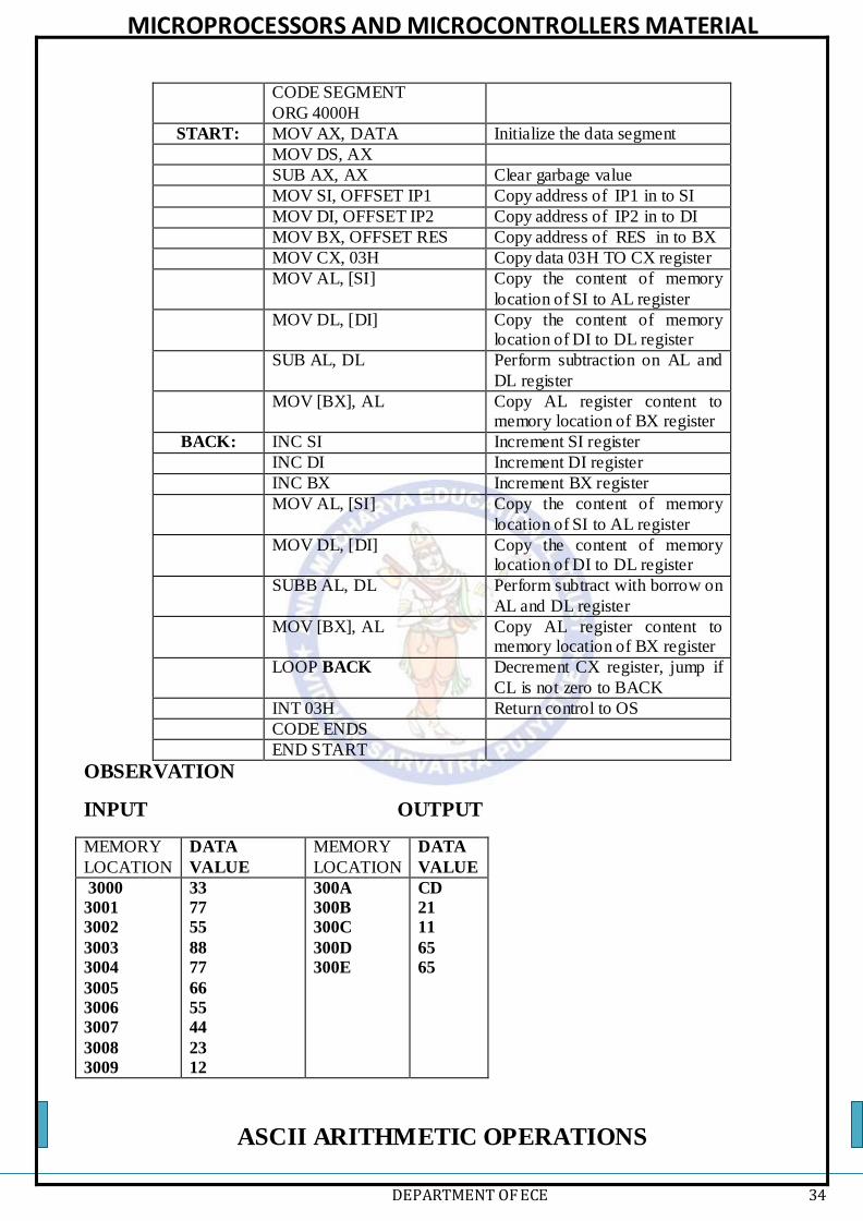
PROGRAM: MULTI BYTE ADDITION
LABEL MNEMONICS COMMENTS
ASSUME CS:CODE,
DS:DATA
DATA SEGMENT ORG 3000H
IP1 DD 1223445566H IP2 DD 7788557733H RES DD 0000000000H
DATA ENDS
CODE SEGMENT ORG 4000H
START: MOV AX, DATA Initialize the data segment
MOV DS, AX
SUB AX, AX Clear garbage value
MOV SI, OFFSET IP1 Copy address of IP1 in to SI
MOV DI, OFFSET IP2 Copy address of IP2 in to DI

MICROPROCESSORS AND MICROCONTROLLERS MATERIAL
DEPARTMENT OF ECE 33
MOV BX, OFFSET RES Copy address of RES in to BX
MOV CX, 03H Copy data 03H TO CX register
MOV AL, [SI] Copy the content of memory location of SI to AL register
MOV DL, [DI] Copy the content of memory location of DI to DL register
ADD AL, DL Perform addition on AL and DL register
MOV [BX], AL Copy AL register content to memory location of BX register
BACK: INC SI Increment SI register
INC DI Increment DI register
INC BX Increment BX register
MOV AL, [SI] Copy the content of memory location of SI to AL register
MOV DL, [DI] Copy the content of memory
location of DI to DL register
ADC AL, DL Perform addition with carry on AL and DL register
MOV [BX], AL Copy AL register content to memory location of BX register
LOOP BACK Decrement CX register, jump if CL is not zero to BACK
INT 03H Return control to OS
CODE ENDS
END START
OBSERVATION
INPUT OUTPUT
MEMORY
LOCATION
DATA
VALUE
MEMORY
LOCATION
DATA
VALUE
3000
3001
3002
3003
3004
3005
3006
3007
3008
3009
66
55
44
23
12
33
77
55
88
77
300A
300B
300C
300D
300E
99
CC
99
AB
89
PROGRAM: MULTI BYTE SUBTRACTION
LABEL MNEMONICS COMMENTS
ASSUME CS:CODE, DS:DATA
DATA SEGMENT ORG 3000H IP1 DD 7788557733H
IP2 DD 1223445566H
RES DD 0000000000H DATA ENDS
MICROPROCESSORS AND MICROCONTROLLERS MATERIAL
DEPARTMENT OF ECE 34
CODE SEGMENT
ORG 4000H
START: MOV AX, DATA Initialize the data segment
MOV DS, AX
SUB AX, AX Clear garbage value
MOV SI, OFFSET IP1 Copy address of IP1 in to SI
MOV DI, OFFSET IP2 Copy address of IP2 in to DI
MOV BX, OFFSET RES Copy address of RES in to BX
MOV CX, 03H Copy data 03H TO CX register
MOV AL, [SI] Copy the content of memory
location of SI to AL register
MOV DL, [DI] Copy the content of memory location of DI to DL register
SUB AL, DL Perform subtraction on AL and
DL register
MOV [BX], AL Copy AL register content to memory location of BX register
BACK: INC SI Increment SI register
INC DI Increment DI register
INC BX Increment BX register
MOV AL, [SI] Copy the content of memory
location of SI to AL register
MOV DL, [DI] Copy the content of memory location of DI to DL register
SUBB AL, DL Perform subtract with borrow on
AL and DL register
MOV [BX], AL Copy AL register content to memory location of BX register
LOOP BACK Decrement CX register, jump if
CL is not zero to BACK
INT 03H Return control to OS
CODE ENDS
END START
OBSERVATION
INPUT OUTPUT
MEMORY
LOCATION
DATA
VALUE
MEMORY
LOCATION
DATA
VALUE
3000
3001
3002
3003
3004
3005
3006
3007
3008
3009
33
77
55
88
77
66
55
44
23
12
300A
300B
300C
300D
300E
CD
21
11
65
65
ASCII ARITHMETIC OPERATIONS

MICROPROCESSORS AND MICROCONTROLLERS MATERIAL
DEPARTMENT OF ECE 35
PROGRAM: ASCII ADDITION
LABEL MNEMONICS COMMENTS
ASSUME CS:CODE,
DS:DATA
DATA SEGMENT ORG 3000H
ASC1 DB 00H ASC2 DB 00H RES DW 0000H
DATA ENDS
CODE SEGMENT ORG 4000H
START: MOV AX, DATA Initialize the data
segment
MOV DS, AX
XOR AX, AX Clear the garbage
MOV AL, ASC1 Copy the content of data from N1 memory
location
MOV BL, ASC2 Copy the content of data from N2 memory
location
ADD AL, BL
Perform addition on AL and BL registers and store result in AL
AAA Perform ASCII
adjustment after addition
OR AX, 3030H
MOV RES, AX Copy the content of
accumulator to RES memory location
INT 03H Return control to OS
CODE ENDS
END START
OBSERVATIONS:
INPUT OUTPUT
MEMORY LOCATION
DATA
VALUE
MEMORY LOCATION
DATA
VALUE
3000
3001
34
38
3002
3003
31H
32H
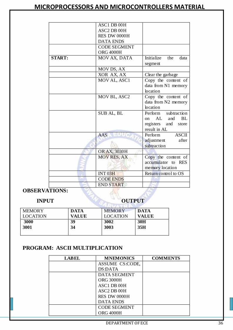
PROGRAM: ASCII SUBTRACTION
LABEL MNEMONICS COMMENTS
ASSUME CS:CODE,
DS:DATA
DATA SEGMENT ORG 3000H
MICROPROCESSORS AND MICROCONTROLLERS MATERIAL
DEPARTMENT OF ECE 36
ASC1 DB 00H
ASC2 DB 00H RES DW 0000H
DATA ENDS
CODE SEGMENT ORG 4000H
START: MOV AX, DATA Initialize the data
segment
MOV DS, AX
XOR AX, AX Clear the garbage
MOV AL, ASC1 Copy the content of data from N1 memory
location
MOV BL, ASC2 Copy the content of data from N2 memory location
SUB AL, BL
Perform subtraction on AL and BL registers and store
result in AL
AAS Perform ASCII adjustment after
subtraction
OR AX, 3030H
MOV RES, AX Copy the content of accumulator to RES memory location
INT 03H Return control to OS
CODE ENDS
END START
OBSERVATIONS:
INPUT OUTPUT
MEMORY LOCATION
DATA
VALUE
MEMORY LOCATION
DATA
VALUE
3000
3001
39
34
3002
3003
30H
35H
PROGRAM: ASCII MULTIPLICATION
LABEL MNEMONICS COMMENTS
ASSUME CS:CODE, DS:DATA
DATA SEGMENT ORG 3000H
ASC1 DB 00H ASC2 DB 00H
RES DW 0000H DATA ENDS
CODE SEGMENT
ORG 4000H

MICROPROCESSORS AND MICROCONTROLLERS MATERIAL
DEPARTMENT OF ECE 37
START: MOV AX, DATA Initialize the data
segment
MOV DS, AX
XOR AX, AX Clear the garbage
MOV AL, ASC1 Copy the content of data from N1 memory
location
MOV BL, ASC2 Copy the content of data from N2 memory
location
MUL BL
Perform multiplication on AL
and BL registers and store result in AL
AAM Perform ASCII adjustment after
addition
OR AX, 3030H
MOV RES, AX Copy the content of accumulator to RES
memory location
INT 03H Return control to OS
CODE ENDS
END START
OBSERVATIONS:
INPUT OUTPUT
MEMORY
LOCATION
DATA
VALUE
MEMORY
LOCATION
DATA
VALUE
3000
3001
06
02
3002
3003
31H
32H
PROGRAM: ASCII DIVISION
LABEL MNEMONICS COMMENTS
ASSUME CS:CODE,
DS:DATA
DATA SEGMENT ORG 3000H
ASC1 DW 00H ASC2 DB 00H RES DW 0000H
DATA ENDS
CODE SEGMENT ORG 4000H
START: MOV AX, DATA Initialize the data

MICROPROCESSORS AND MICROCONTROLLERS MATERIAL
DEPARTMENT OF ECE 38
segment
MOV DS, AX
XOR AX, AX Clear the garbage
MOV AX, ASC1 Copy the content of data from N1 memory location
MOV BL, ASC2 Copy the content of data from N2 memory location
AAD Perform ASCII
adjustment before division
DIV BL
Perform division on
AX and BL registers and store result in AX
OR AX, 3030H
MOV RES, AX Copy the content of
accumulator to RES memory location
INT 03H Return control to OS
CODE ENDS
END START
OBSERVATIONS:
INPUT OUTPUT
MEMORY
LOCATION
DATA
VALUE
MEMORY
LOCATION
DATA
VALUE
3000
3001
3002
06
03
05
3002
3003
37H
31H
LOGICAL OPERATIONS
PROGRAM: LOGICAL AND OPERATION
OFFSET
ADDRESS
LABEL MNEMONICS COMMENTS
ASSUME CS:CODE, DS:DATA
DATA SEGMENT

MICROPROCESSORS AND MICROCONTROLLERS MATERIAL
DEPARTMENT OF ECE 39
ORG 3000H
OP1 DB 00H OP2 DB 00H
RES DB 00H DATA ENDS
CODE SEGMENT
ORG 4000H
START: MOV AX, DATA Initialize the data segment
MOV DS, AX
MOV AX, 0000 Clear the accumulator
MOV AL, OP1 Copy the content of
data from OP1 memory location
MOV BL, OP2 Copy the content of data from OP2
memory location
AND AL, BL Perform AND on AL and BL registers and
store result in AL
MOV RES, AL Copy the content of accumulator to RES
memory location
INT 03H Return control to OS
CODE ENDS
END START
OBSERVATIONS:
INPUT OUTPUT
MEMORY LOCATION
DATA
VALUE
MEMORY LOCATION
DATA
VALUE
3000
3001
35
0F
3002
05
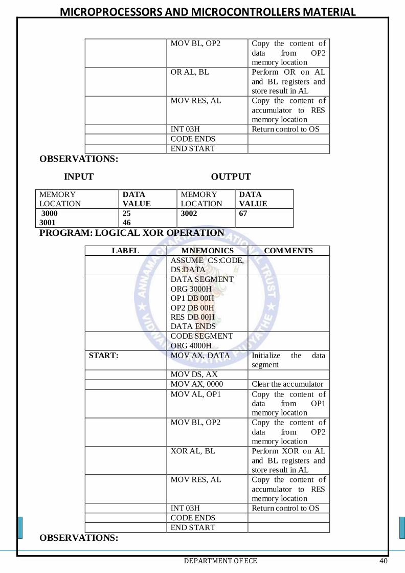
PROGRAM: LOGICAL OR OPERATION
LABEL MNEMONICS COMMENTS
ASSUME CS:CODE, DS:DATA
DATA SEGMENT ORG 3000H
OP1 DB 00H OP2 DB 00H
RES DB 00H DATA ENDS
CODE SEGMENT ORG 4000H
START: MOV AX, DATA Initialize the data segment
MOV DS, AX
MOV AX, 0000 Clear the accumulator
MOV AL, OP1 Copy the content of
data from OP1 memory location
MICROPROCESSORS AND MICROCONTROLLERS MATERIAL
DEPARTMENT OF ECE 40
MOV BL, OP2 Copy the content of
data from OP2 memory location
OR AL, BL Perform OR on AL
and BL registers and store result in AL
MOV RES, AL Copy the content of
accumulator to RES memory location
INT 03H Return control to OS
CODE ENDS
END START
OBSERVATIONS:
INPUT OUTPUT
MEMORY LOCATION
DATA
VALUE
MEMORY LOCATION
DATA
VALUE
3000
3001
25
46
3002
67
PROGRAM: LOGICAL XOR OPERATION
LABEL MNEMONICS COMMENTS
ASSUME CS:CODE, DS:DATA
DATA SEGMENT
ORG 3000H OP1 DB 00H
OP2 DB 00H RES DB 00H DATA ENDS
CODE SEGMENT
ORG 4000H
START: MOV AX, DATA Initialize the data segment
MOV DS, AX
MOV AX, 0000 Clear the accumulator
MOV AL, OP1 Copy the content of data from OP1 memory location
MOV BL, OP2 Copy the content of
data from OP2 memory location
XOR AL, BL Perform XOR on AL
and BL registers and store result in AL
MOV RES, AL Copy the content of
accumulator to RES memory location
INT 03H Return control to OS
CODE ENDS
END START
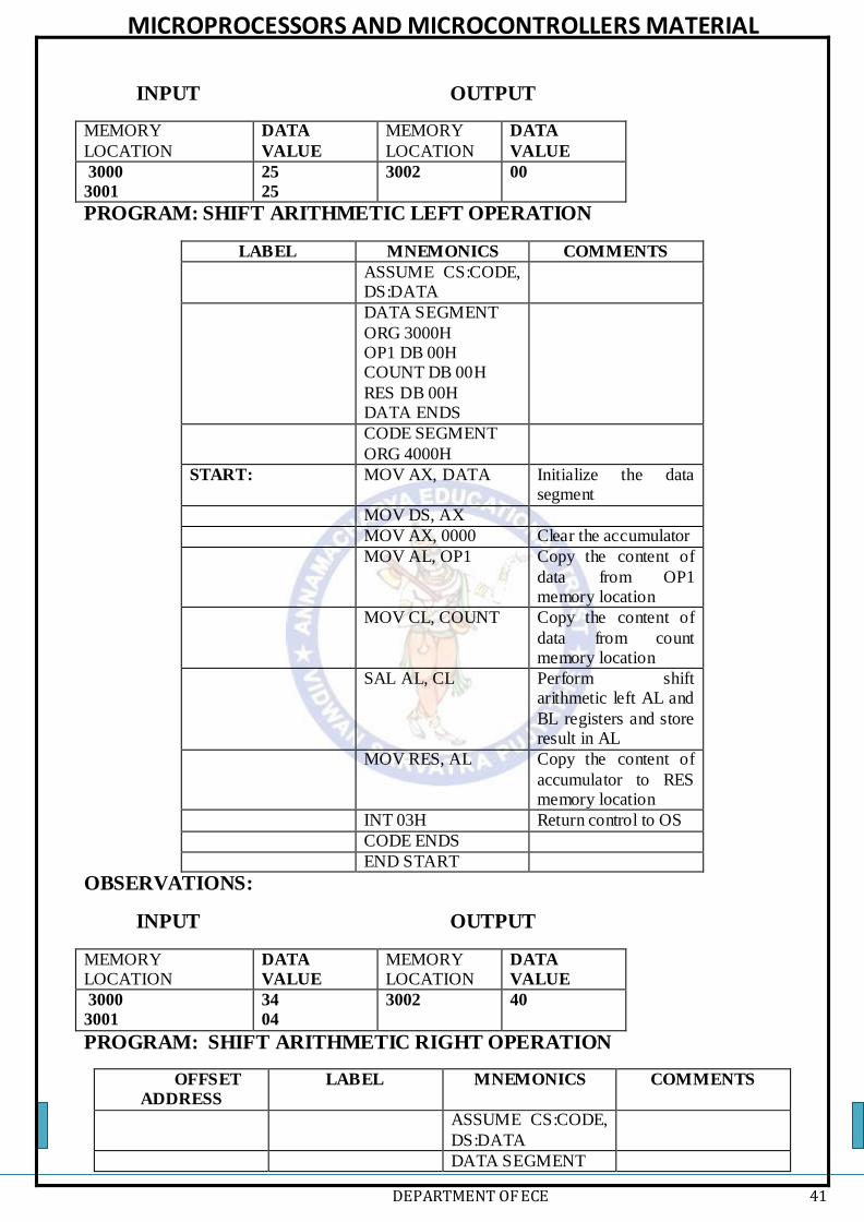
OBSERVATIONS:
MICROPROCESSORS AND MICROCONTROLLERS MATERIAL
DEPARTMENT OF ECE 41
INPUT OUTPUT
MEMORY
LOCATION
DATA
VALUE
MEMORY
LOCATION
DATA
VALUE
3000
3001
25
25
3002
00
PROGRAM: SHIFT ARITHMETIC LEFT OPERATION
LABEL MNEMONICS COMMENTS
ASSUME CS:CODE, DS:DATA
DATA SEGMENT
ORG 3000H OP1 DB 00H COUNT DB 00H
RES DB 00H DATA ENDS
CODE SEGMENT
ORG 4000H
START: MOV AX, DATA Initialize the data segment
MOV DS, AX
MOV AX, 0000 Clear the accumulator
MOV AL, OP1 Copy the content of
data from OP1 memory location
MOV CL, COUNT Copy the content of
data from count memory location
SAL AL, CL Perform shift arithmetic left AL and
BL registers and store result in AL
MOV RES, AL Copy the content of
accumulator to RES memory location
INT 03H Return control to OS
CODE ENDS
END START
OBSERVATIONS:
INPUT OUTPUT
MEMORY LOCATION
DATA
VALUE
MEMORY LOCATION
DATA
VALUE
3000
3001
34
04
3002
40
PROGRAM: SHIFT ARITHMETIC RIGHT OPERATION
OFFSET
ADDRESS
LABEL MNEMONICS COMMENTS
ASSUME CS:CODE,
DS:DATA
DATA SEGMENT

MICROPROCESSORS AND MICROCONTROLLERS MATERIAL
DEPARTMENT OF ECE 42
ORG 3000H
OP1 DB 00H COUNT DB 00H
RES DB 00H DATA ENDS
CODE SEGMENT
ORG 4000H
START: MOV AX, DATA Initialize the data segment
MOV DS, AX
MOV AX, 0000 Clear the accumulator
MOV AL, OP1 Copy the content of
data from OP1 memory location
MOV CL, COUNT Copy the content of data from count
memory location
SAR AL, CL Perform shift arithmetic right AL
and BL registers and store result in AL
MOV RES, AL Copy the content of
accumulator to RES memory location
INT 03H Return control to OS
CODE ENDS
END START
OBSERVATIONS:
INPUT OUTPUT
MEMORY
LOCATION
DATA
VALUE
MEMORY
LOCATION
DATA
VALUE
3000
3001
34
04
3002
03
PROGRAM: SHIFT LOGICAL LEFT OPERATION
LABEL MNEMONICS COMMENTS
ASSUME CS:CODE, DS:DATA
DATA SEGMENT ORG 3000H
OP1 DB 00H COUNT DB 00H
RES DB 00H DATA ENDS
CODE SEGMENT ORG 4000H
START: MOV AX, DATA Initialize the data segment

MICROPROCESSORS AND MICROCONTROLLERS MATERIAL
DEPARTMENT OF ECE 43
MOV DS, AX
MOV AX, 0000 Clear the accumulator
MOV AL, OP1 Copy the content of data from OP1 memory location
MOV CL, COUNT Copy the content of data from count memory location to CL
SHL AL, CL Perform shift arithmetic left AL and BL registers and store result in AL
MOV RES, AL Copy the content of accumulator to RES memory location
INT 03H Return control to OS
CODE ENDS
END START
OBSERVATIONS:
INPUT OUTPUT
MEMORY
LOCATION
DATA
VALUE
MEMORY
LOCATION
DATA
VALUE
3000
3001
34
04
3002
40
PROGRAM: SHIFT LOGICAL RIGHT OPERATIONS
LABEL MNEMONICS COMMENTS
ASSUME CS:CODE, DS:DATA
DATA SEGMENT ORG 3000H
OP1 DB 00H COUNT DB 00H
RES DB 00H DATA ENDS
CODE SEGMENT ORG 4000H
START: MOV AX, DATA Initialize the data segment
MOV DS, AX
MOV AX, 0000 Clear the accumulator
MOV AL, OP1 Copy the content of
data from OP1 memory location
MOV CL, COUNT Copy the content of data from count
memory location to CL
SHR AL, CL Perform shift logical
right AL and BL registers and store result in AL
MOV RES, AL Copy the content of accumulator to RES

MICROPROCESSORS AND MICROCONTROLLERS MATERIAL
DEPARTMENT OF ECE 44
memory location
INT 03H Return control to OS
CODE ENDS
END START
OBSERVATIONS:
INPUT OUTPUT
MEMORY LOCATION
DATA
VALUE
MEMORY LOCATION
DATA
VALUE
3000
3001
35
04
3002
03
PROGRAM: ROTATE LEFT WITHOUT CARRY OPERATION
LABEL MNEMONICS COMMENTS
ASSUME CS:CODE,
DS:DATA
DATA SEGMENT ORG 3000H
OP1 DB 00H COUNT DB 00H
RES DB 00H DATA ENDS
CODE SEGMENT ORG 4000H
START: MOV AX, DATA Initialize the data
segment
MOV DS, AX
MOV AX, 0000 Clear the accumulator
MOV AL, OP1 Copy the content of data from OP1
memory location
MOV CL, COUNT Copy the content of data from count
memory location to CL
ROL AL, CL Perform rotate left
without carry AL and BL registers and store result in AL
MOV RES, AL Copy the content of
accumulator to RES memory location
INT 03H Return control to OS
CODE ENDS
END START
OBSERVATIONS:
INPUT OUTPUT
MEMORY LOCATION
DATA
VALUE
MEMORY LOCATION
DATA
VALUE
3000
3001
23
04
3002
32
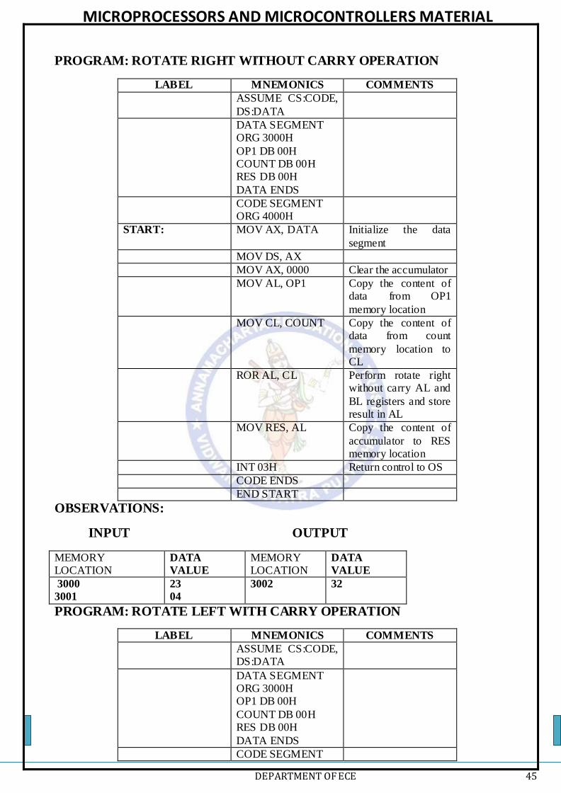
MICROPROCESSORS AND MICROCONTROLLERS MATERIAL
DEPARTMENT OF ECE 45
PROGRAM: ROTATE RIGHT WITHOUT CARRY OPERATION
LABEL MNEMONICS COMMENTS
ASSUME CS:CODE,
DS:DATA
DATA SEGMENT ORG 3000H
OP1 DB 00H COUNT DB 00H RES DB 00H
DATA ENDS
CODE SEGMENT ORG 4000H
START: MOV AX, DATA Initialize the data
segment
MOV DS, AX
MOV AX, 0000 Clear the accumulator
MOV AL, OP1 Copy the content of data from OP1
memory location
MOV CL, COUNT Copy the content of data from count
memory location to CL
ROR AL, CL Perform rotate right without carry AL and
BL registers and store result in AL
MOV RES, AL Copy the content of
accumulator to RES memory location
INT 03H Return control to OS
CODE ENDS
END START
OBSERVATIONS:
INPUT OUTPUT
MEMORY LOCATION
DATA
VALUE
MEMORY LOCATION
DATA
VALUE
3000
3001
23
04
3002
32
PROGRAM: ROTATE LEFT WITH CARRY OPERATION
LABEL MNEMONICS COMMENTS
ASSUME CS:CODE, DS:DATA
DATA SEGMENT ORG 3000H OP1 DB 00H
COUNT DB 00H RES DB 00H
DATA ENDS
CODE SEGMENT
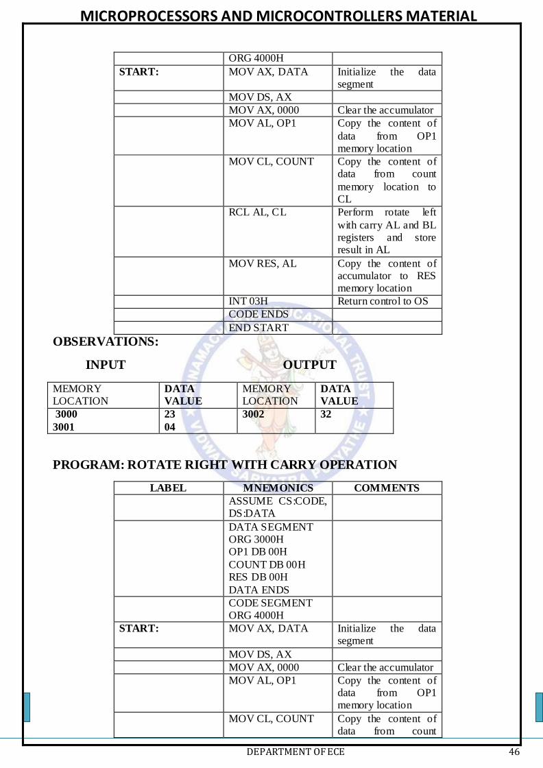
MICROPROCESSORS AND MICROCONTROLLERS MATERIAL
DEPARTMENT OF ECE 46
ORG 4000H
START: MOV AX, DATA Initialize the data segment
MOV DS, AX
MOV AX, 0000 Clear the accumulator
MOV AL, OP1 Copy the content of
data from OP1 memory location
MOV CL, COUNT Copy the content of data from count
memory location to CL
RCL AL, CL Perform rotate left
with carry AL and BL registers and store result in AL
MOV RES, AL Copy the content of accumulator to RES memory location
INT 03H Return control to OS
CODE ENDS
END START
OBSERVATIONS:
INPUT OUTPUT
MEMORY LOCATION
DATA
VALUE
MEMORY LOCATION
DATA
VALUE
3000
3001
23
04
3002
32
PROGRAM: ROTATE RIGHT WITH CARRY OPERATION
LABEL MNEMONICS COMMENTS
ASSUME CS:CODE, DS:DATA
DATA SEGMENT ORG 3000H OP1 DB 00H
COUNT DB 00H RES DB 00H
DATA ENDS
CODE SEGMENT ORG 4000H
START: MOV AX, DATA Initialize the data segment
MOV DS, AX
MOV AX, 0000 Clear the accumulator
MOV AL, OP1 Copy the content of data from OP1 memory location
MOV CL, COUNT Copy the content of data from count

MICROPROCESSORS AND MICROCONTROLLERS MATERIAL
DEPARTMENT OF ECE 47
memory location to
CL
RCR AL, CL Perform rotate right with carry AL and BL
registers and store result in AL
MOV RES, AL Copy the content of
accumulator to RES memory location
INT 03H Return control to OS
CODE ENDS
END START
OBSERVATIONS:
INPUT OUTPUT
MEMORY LOCATION
DATA
VALUE
MEMORY LOCATION
DATA
VALUE
3000
3001
35
04
3002
46
PACKED AND UNPACKED BCD NUMBERS
PROGRAM: PACKED TO UNPACKED BCD NUMBERS
LABEL MNEMONICS COMMENTS
ASSUME CS:CODE, DS:DATA
DATA SEGMENT
ORG 3000H IP1 DB 00H COUNT DB 00H
RES DW 00H DATA ENDS
CODE SEGMENT
ORG 4000H
START: MOV AX, DATA Initialize the data segment
MOV DS, AX
MOV AX, 0000 Clear the accumulator
MOV AL, IP1 Copy the content of
data from IP1 memory location
MOV DL, AL Move data from AL to
DL register
MOV CL, COUNT Copy the content of data from count
memory location to CL
AND AL, 0F0H Perform AND operation to hide the
data of higher nibble
ROR AL, CL Perform rotate right without carry AL by
CL registers and store
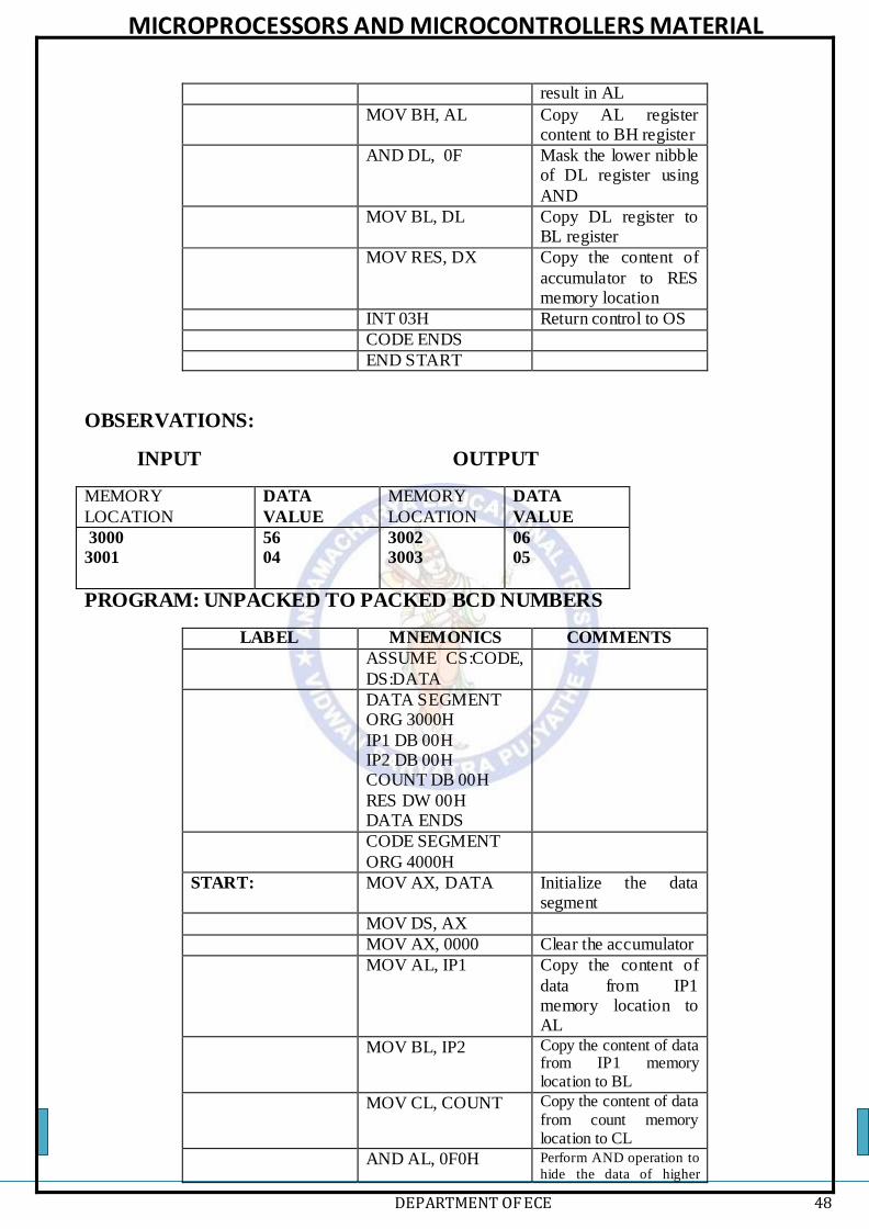
MICROPROCESSORS AND MICROCONTROLLERS MATERIAL
DEPARTMENT OF ECE 48
result in AL
MOV BH, AL Copy AL register content to BH register
AND DL, 0F Mask the lower nibble of DL register using
AND
MOV BL, DL Copy DL register to BL register
MOV RES, DX Copy the content of
accumulator to RES memory location
INT 03H Return control to OS
CODE ENDS
END START
OBSERVATIONS:
INPUT OUTPUT
MEMORY
LOCATION
DATA
VALUE
MEMORY
LOCATION
DATA
VALUE
3000
3001
56
04
3002
3003
06
05
PROGRAM: UNPACKED TO PACKED BCD NUMBERS
LABEL MNEMONICS COMMENTS
ASSUME CS:CODE,
DS:DATA
DATA SEGMENT ORG 3000H
IP1 DB 00H IP2 DB 00H COUNT DB 00H
RES DW 00H DATA ENDS
CODE SEGMENT
ORG 4000H
START: MOV AX, DATA Initialize the data segment
MOV DS, AX
MOV AX, 0000 Clear the accumulator
MOV AL, IP1 Copy the content of
data from IP1 memory location to AL
MOV BL, IP2 Copy the content of data from IP1 memory location to BL
MOV CL, COUNT Copy the content of data from count memory location to CL
AND AL, 0F0H Perform AND operation to
hide the data of higher

MICROPROCESSORS AND MICROCONTROLLERS MATERIAL
DEPARTMENT OF ECE 49
nibble ROR AL, CL Perform rotate right
without carry AL by CL
registers and store result in
AL AND BL, 0F Mask the lower nibble of
DL register using AND OR AL,BL Perform OR operation
on AL and BL registers
MOV RES, AX Copy the content of
accumulator to RES memory location
INT 03H Return control to OS
CODE ENDS
END START
OBSERVATIONS:
INPUT OUTPUT
MEMORY LOCATION
DATA
VALUE
MEMORY LOCATION
DATA
VALUE
3000
3001
06
04
3002
3003
64
SORTING THE GIVEN NUMBERS
PROGRAM: ASCENDING ORDER
LABEL MNEMONICS COMMENTS
ASSUME CS:CODE,
DS:DATA
DATA SEGMENT ORG 3000H COUNT EQU 04H
LIST DB 00H,00H,00H
DATA ENDS
CODE SEGMENT ORG 4000H
START: MOV AX, DATA Initialize the data
segment
MOV DS, AX
XOR AX, AX Clear the garbage data
MOV CX, COUNT-1 Decremented count is loaded to CX register
MOV SI, OFFSET
LIST
LIST address is
copied to SI
L3: MOV AL, [SI] SI register address content is copied to
AL register
MOV DX, CX CX register is loaded to DX register
L2: INC SI Increment SI register
MOV BL, [SI] Move SI register
memory location

MICROPROCESSORS AND MICROCONTROLLERS MATERIAL
DEPARTMENT OF ECE 50
content to BL register
CMP AL, BL Perform comparison on AL and BL
JB L1 If CF is zero, jump to L1
XCHG AL, [SI] Exchange the contents
of AL and SI register address contents
L1: LOOP L2 Decrement CX
register and check CX is zero or not, if CX ≠
0, jump to L2
SUB SI, DX Perform subtract on SI and DX registers
INC SI Increment SI register
MOV CX, DX DX register is loaded
to CX register
LOOP L3 Decrement CX register and check CX is zero or not, if CX ≠
0, jump to L3
INT 03H Return control to OS
CODE ENDS
END START
OBSERVATIONS:
INPUT OUTPUT
MEMORY
LOCATION
DATA
VALUE
MEMORY
LOCATION
DATA
VALUE
3000
3001
3002
3003
06
04
25
12
3000
3001
3002
3003
04
06
12
25
PROGRAM: DESCENDING ORDER
OFFSET
ADDRESS
LABEL MNEMONICS COMMENTS
ASSUME CS:CODE,
DS:DATA
DATA SEGMENT ORG 3000H
COUNT EQU 04H LIST DB 00H,00H,00H
DATA ENDS
CODE SEGMENT ORG 4000H
START: MOV AX, DATA Initialize the data
segment
MOV DS, AX
XOR AX, AX Clear the garbage data
MOV CX, COUNT-1 Decremented count is
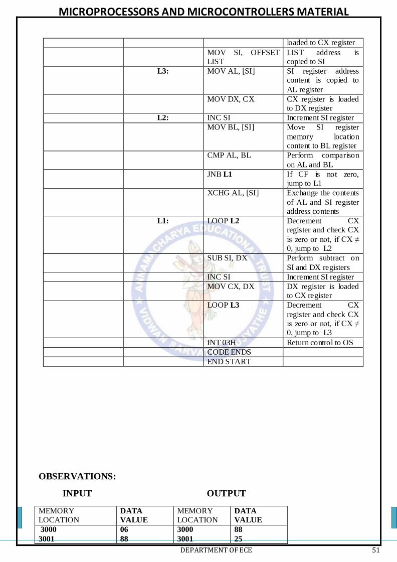
MICROPROCESSORS AND MICROCONTROLLERS MATERIAL
DEPARTMENT OF ECE 51
loaded to CX register
MOV SI, OFFSET LIST
LIST address is copied to SI
L3: MOV AL, [SI] SI register address content is copied to
AL register
MOV DX, CX CX register is loaded to DX register
L2: INC SI Increment SI register
MOV BL, [SI] Move SI register
memory location content to BL register
CMP AL, BL Perform comparison
on AL and BL
JNB L1 If CF is not zero, jump to L1
XCHG AL, [SI] Exchange the contents
of AL and SI register address contents
L1: LOOP L2 Decrement CX register and check CX
is zero or not, if CX ≠ 0, jump to L2
SUB SI, DX Perform subtract on
SI and DX registers
INC SI Increment SI register
MOV CX, DX DX register is loaded to CX register
LOOP L3 Decrement CX
register and check CX is zero or not, if CX ≠ 0, jump to L3
INT 03H Return control to OS
CODE ENDS
END START
OBSERVATIONS:
INPUT OUTPUT
MEMORY LOCATION
DATA
VALUE
MEMORY LOCATION
DATA
VALUE
3000
3001
06
88
3000
3001
88
25

MICROPROCESSORS AND MICROCONTROLLERS MATERIAL
DEPARTMENT OF ECE 52
3002
3003
25
12
3002
3003
12
06
STRING OPERATIONS
PROGRAM: LENGTH OF THE STRING
LABEL MNEMONICS COMMENTS
ASSUME CS:CODE, DS:DATA
DATA SEGMENT
ORG 3000H STRING1 DB ‘EMPTY VESSELS
$’ STRLEN EQU ($-
STRING1) DATA ENDS
CODE SEGMENT ORG 4000H
START: MOV AX, DATA Initialize the data segment
MOV DS, AX
SUB CL, CL Clear the CL register
MOV BL, STRLEN Copy the string length to BL
MOV SI, OFFSET STRING1
STRING1 offset address is copied to SI register
BACK: LODSB Load string byte
INC CL Increment CL
CMP AL, ‘$’ Compare AL with ‘$’
JNE BACK Jump if AL ≠ ‘$’, to BACK
MOV RES, CL Copy CL to RES memory location
INT 03H Return control to OS
CODE ENDS
END START
OBSERVATIONS:
INPUT OUTPUT
MEMORY LOCATION
DATA
VALUE
MEMORY LOCATION
DATA
VALUE
3000
3001
3002
3003
3004
3005
3006
3007
3008
45
4D
50
54
59
20
56
45
53
300E 0E
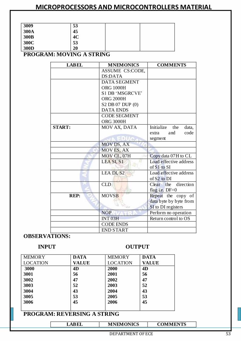
MICROPROCESSORS AND MICROCONTROLLERS MATERIAL
DEPARTMENT OF ECE 53
3009
300A
300B
300C
300D
53
45
4C
53
20
PROGRAM: MOVING A STRING
LABEL MNEMONICS COMMENTS
ASSUME CS:CODE, DS:DATA
DATA SEGMENT
ORG 1000H S1 DB ‘MSGRCVE’ ORG 2000H
S2 DB 07 DUP (0) DATA ENDS
CODE SEGMENT
ORG 3000H
START: MOV AX, DATA Initialize the data, extra and code segment
MOV DS, AX
MOV ES, AX
MOV CL, 07H Copy data 07H to CL
LEA SI, S1 Load effective address of S1 to SI
LEA DI, S2 Load effective address
of S2 to DI
CLD Clear the direction flag i.e. DF=0
REP: MOVSB Repeat the copy of data byte by byte from
SI to DI registers
NOP Perform no operation
INT 03H Return control to OS
CODE ENDS
END START
OBSERVATIONS:
INPUT OUTPUT
MEMORY
LOCATION
DATA
VALUE
MEMORY
LOCATION
DATA
VALUE
3000
3001
3002
3003
3004
3005
3006
4D
56
47
52
43
53
45
2000
2001
2002
2003
2004
2005
2006
4D
56
47
52
43
53
45
PROGRAM: REVERSING A STRING
LABEL MNEMONICS COMMENTS

MICROPROCESSORS AND MICROCONTROLLERS MATERIAL
DEPARTMENT OF ECE 54
ASSUME CS:CODE,
DS:DATA
DATA SEGMENT ORG 2000H
STR1 DB ‘EMPTY $’ STRLEN EQU ($-
STR1) ORG 3000H STR2 DB 05H
DATA ENDS
CODE SEGMENT
ORG 3000H
START: MOV AX, DATA Initialize the data segment
MOV DS, AX
MOV SI, OFFSET
STR1
Move address of str1
to SI register
MOV CX, STRLEN Copy the length of the string1
MOV DI, OFFSET
STR2
Copy STR2 offset to
DI register
ADD DI, 06 Addition of DI to 05H
MOV CX, STRLEN Move strlen data to cx
L1: LODSB Load data byte from SI to AL and increment SI
MOV [DI], AL Copy data of AL to extra segment address in DI register
DEC DI Decrement DI
LOOP L1 Decrement CX, check
CX≠0
NOP Repeat copying of data from SI to DI in extra register
INT 03H Return control to OS
CODE ENDS
END START
OBSERVATIONS:
INPUT OUTPUT
MEMORY LOCATION
DATA
VALUE
MEMORY LOCATION
DATA
VALUE
2000
2001
2002
2003
2004
2005
45
4D
50
54
59
24
3000
3001
3002
3003
3004
3005
24
59
54
50
4D
45
PROGRAM: COMPARING TWO STRINGS
LABEL MNEMONICS COMMENTS

MICROPROCESSORS AND MICROCONTROLLERS MATERIAL
DEPARTMENT OF ECE 55
ASSUME CS:CODE,
DS:DATA
DATA SEGMENT ORG 3000H
STR1 DB ‘EMPTY1 $’
STRLEN EQU ($-STR1) ORG 2000H
RES DB 00H ORG 1500H
STR2 DB ‘EMPTY $’ DATA ENDS
CODE SEGMENT ORG 3000H
START: MOV AX, DATA Initialize the data, extra and code segment
MOV DS, AX
MOV ES, AX
MOV BX, OFFSET STR1
Copy STR1 offset to BX register
MOV SI, OFFSET
STR1 Copy STR1 offset to
SI register
MOV DI, OFFSET STR2
Copy STR2 offset to DI register
CLD Clear the direction
flag i.e. DF=0
MOV CX, STRLEN Move strlen data to CX
REPNE: CMPSB Compare every byte
of a string
JZ NEXT If ZF=0, jump to NEXT
MOV AH, 09H Copy 09 to AH
register
MOV DX, ‘A’ Copy ‘A’ to DX register
INT 21H Interrupt 21H to run
function from DOS
JMP EXIT
NEXT: MOV AH, 09H Copy 09 to AH register
MOV DX, ‘E’ Copy ‘E’ to DX
register
INT 21H Interrupt 21H to run function from DOS
EXIT: NOP No operation
MOV RES, DL Copy DL to res, 4CH
to AH
MOV AH, 4CH
INT 21H Return control to OS
CODE ENDS
END START
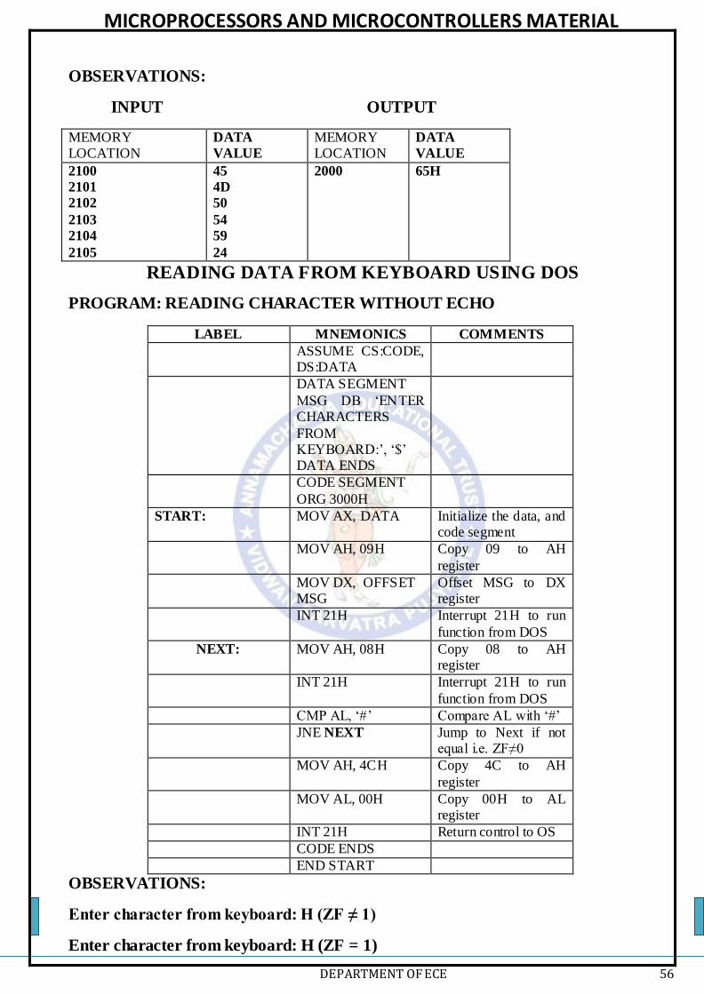
MICROPROCESSORS AND MICROCONTROLLERS MATERIAL
DEPARTMENT OF ECE 56
OBSERVATIONS:
INPUT OUTPUT
MEMORY LOCATION
DATA
VALUE
MEMORY LOCATION
DATA
VALUE
2100
2101
2102
2103
2104
2105
45
4D
50
54
59
24
2000 65H
READING DATA FROM KEYBOARD USING DOS
PROGRAM: READING CHARACTER WITHOUT ECHO
LABEL MNEMONICS COMMENTS
ASSUME CS:CODE, DS:DATA
DATA SEGMENT
MSG DB ‘ENTER CHARACTERS
FROM KEYBOARD:’, ‘$’ DATA ENDS
CODE SEGMENT
ORG 3000H
START: MOV AX, DATA Initialize the data, and code segment
MOV AH, 09H Copy 09 to AH
register
MOV DX, OFFSET MSG
Offset MSG to DX register
INT 21H Interrupt 21H to run
function from DOS
NEXT: MOV AH, 08H Copy 08 to AH register
INT 21H Interrupt 21H to run
function from DOS
CMP AL, ‘#’ Compare AL with ‘#’
JNE NEXT Jump to Next if not equal i.e. ZF≠0
MOV AH, 4CH Copy 4C to AH
register
MOV AL, 00H Copy 00H to AL register
INT 21H Return control to OS
CODE ENDS
END START
OBSERVATIONS:
Enter character from keyboard: H (ZF ≠ 1)
Enter character from keyboard: H (ZF = 1)

MICROPROCESSORS AND MICROCONTROLLERS MATERIAL
DEPARTMENT OF ECE 57
PROGRAM: READING CHARACTER WITH ECHO
LABEL MNEMONICS COMMENTS
ASSUME CS:CODE,
DS:DATA
DATA SEGMENT MSG DB ‘ENTER
CHARACTERS FROM KEYBOARD:’, ‘$’
DATA ENDS
CODE SEGMENT ORG 3000H
START: MOV AX, DATA Initialize the data, and code segment
MOV AH, 09H Copy 09 to AH register
MOV DX, OFFSET
MSG
Offset MSG to DX
register
INT 21H Interrupt 21H to run function from DOS
NEXT: MOV AH, 08H Copy 08 to AH
register
INT 21H Interrupt 21H to run function from DOS
MOV AH, 02H Copy 02H to AH register
MOV DL, AL Copy AL to DL
register
INT 21H Interrupt 21H to run function from DOS
CMP AL, ‘#’ Compare AL with ‘#’
JNE NEXT Jump to Next if not
equal i.e. ZF≠0
MOV AH, 4CH Copy 4C to AH register
MOV AL, 00H Copy 00H to AL
register
INT 21H Return control to OS
CODE ENDS
END START
OBSERVATIONS:
Enter character from keyboard: H (ZF ≠ 1)
Enter character from keyboard: H (ZF = 1)
PROGRAM: DISPLAYING A MESSAGE ON SCREEN
LABEL MNEMONICS COMMENTS
ASSUME CS:CODE, DS:DATA
DATA SEGMENT
MSG DB ‘SV
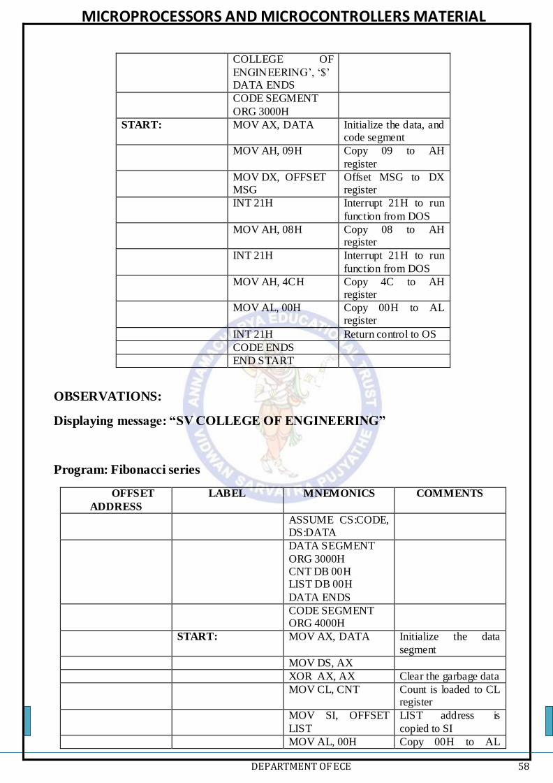
MICROPROCESSORS AND MICROCONTROLLERS MATERIAL
DEPARTMENT OF ECE 58
COLLEGE OF
ENGINEERING’, ‘$’ DATA ENDS
CODE SEGMENT
ORG 3000H
START: MOV AX, DATA Initialize the data, and code segment
MOV AH, 09H Copy 09 to AH
register
MOV DX, OFFSET MSG
Offset MSG to DX register
INT 21H Interrupt 21H to run
function from DOS
MOV AH, 08H Copy 08 to AH register
INT 21H Interrupt 21H to run
function from DOS
MOV AH, 4CH Copy 4C to AH register
MOV AL, 00H Copy 00H to AL register
INT 21H Return control to OS
CODE ENDS
END START
OBSERVATIONS:
Displaying message: “SV COLLEGE OF ENGINEERING”
Program: Fibonacci series
OFFSET
ADDRESS
LABEL MNEMONICS COMMENTS
ASSUME CS:CODE, DS:DATA
DATA SEGMENT
ORG 3000H CNT DB 00H LIST DB 00H
DATA ENDS
CODE SEGMENT ORG 4000H
START: MOV AX, DATA Initialize the data
segment
MOV DS, AX
XOR AX, AX Clear the garbage data
MOV CL, CNT Count is loaded to CL register
MOV SI, OFFSET
LIST
LIST address is
copied to SI
MOV AL, 00H Copy 00H to AL

MICROPROCESSORS AND MICROCONTROLLERS MATERIAL
DEPARTMENT OF ECE 59
register
MOV BL, 01H Copy 01H to AL register
MOV [SI], AL AL register content is copied to address of
SI register
BACK: INC SI Increment SI register
MOV [SI], BL BL register content is copied to address of
SI register
ADD AL, BL Perform addition on AL and BL
XCHG AL, BL Exchange the contents
of AL and BL register
LOOP BACK Decrement CL register and check CX
is zero or not, if CL ≠ 0, jump to BACK
INT 03H Return control to OS
CODE ENDS
END START
OBSERVATIONS
INPUT OUTPUT
MEMORY
LOCATION
DATA
VALUE
MEMORY
LOCATION
DATA
VALUE
3000
08H
3001
3002
3003
3004
3005
3006
3007
3008
3009
00
01
01
02
03
05
08
0D
15
PROGRAM: FACTORIAL OF A NUMBER
OFFSET
ADDRESS
LABEL MNEMONICS COMMENTS
ASSUME CS:CODE, DS:DATA
DATA SEGMENT ORG 3000H N1 DB 00H
RES DW 00H DATA ENDS
CODE SEGMENT
ORG 4000H
START: MOV AX, DATA Initialize the data segment
MOV DS, AX
XOR AX, AX Clear the garbage data
MOV CL, N1 N1 is loaded to CL

MICROPROCESSORS AND MICROCONTROLLERS MATERIAL
DEPARTMENT OF ECE 60
register
MOV AX, 01H Copy 01H to AX register
L1: MUL CL Perform multiplication on CL
and AL
LOOP L1 Decrement CL register and check CL
is zero or not, if CL ≠ 0, jump to BACK
MOV RES, AX Copy the data of AX
to RES address
INT 03H Return control to OS
CODE ENDS
END START
OBSERVATIONS:
INPUT OUTPUT
MEMORY LOCATION
DATA
VALUE
MEMORY LOCATION
DATA
VALUE
3000
05H
3001
3002
00
78
PROGRAM: SUM OF ‘N’ NUMBERS
OFFSET
ADDRESS
LABEL MNEMONICS COMMENTS
ASSUME CS:CODE, DS:DATA
DATA SEGMENT ORG 3000H CNT DB 00H
LIST DB 00H RES DW 00H
DATA ENDS
CODE SEGMENT ORG 4000H
START: MOV AX, DATA Initialize the data segment
MOV DS, AX
MOV AX, 00H Copy 00H to AX register
MOV BX, 00H Copy 00H to BX register
MOV CL, CNT CNT is loaded to CL register
MOV SI, OFFSET LIST
Copy address of LIST to SI address
L1: MOV AL, [SI] Copy content of SI to
AL register
ADD BX, AX Perform addition of

MICROPROCESSORS AND MICROCONTROLLERS MATERIAL
DEPARTMENT OF ECE 61
AX and BX register
INC SI Increment SI register
LOOP L1 Decrement CL register and check CL is zero or not, if CL ≠
0, jump to BACK
MOV RES, BX Copy the data of BX to RES address
INT 03H Return control to OS
CODE ENDS
END START
OBSERVATIONS:
INPUT OUTPUT
MEMORY LOCATION
DATA
VALUE
MEMORY LOCATION
DATA
VALUE
3000
3001
3002
3003
3004
04
05
09
08
03
3005
3006
19
00
PROGRAM: SUM OF SQUARES FOR ‘N’ NUMBERS
OFFSET
ADDRESS
LABEL MNEMONICS COMMENTS
ASSUME CS:CODE, DS:DATA
DATA SEGMENT
ORG 3000H CNT DB 00H LIST DB 00H
RES DW 00H DATA ENDS
CODE SEGMENT
ORG 4000H
START: MOV AX, DATA Initialize the data segment
MOV DS, AX
MOV AX, 00H Copy 00H to AX
register
MOV BX, 00H Copy 00H to BX register
MOV CL, CNT CNT is loaded to CL
register
MOV SI, OFFSET LIST
Copy address of LIST to SI address
L1: MOV AL, [SI] Copy content of SI to
AL register

MICROPROCESSORS AND MICROCONTROLLERS MATERIAL
DEPARTMENT OF ECE 62
MUL AL Perform
multiplication on AL and AL
ADD BX, AX Perform addition of
AX and BX register
INC SI Increment SI register
LOOP L1 Decrement CL register and check CL
is zero or not, if CL ≠ 0, jump to BACK
MOV RES, BX Copy the data of BX
to RES address
INT 03H Return control to OS
CODE ENDS
END START
OBSERVATIONS:
INPUT OUTPUT
MEMORY LOCATION
DATA
VALUE
MEMORY LOCATION
DATA
VALUE
3000
3001
3002
3003
3004
04
05
09
08
03
3005
3006
0B3
00
PROGRAM: SUM OF CUBES FOR ‘N’ NUMBERS
OFFSET
ADDRESS
LABEL MNEMONICS COMMENTS
ASSUME CS:CODE, DS:DATA
DATA SEGMENT ORG 3000H CNT DB 00H
LIST DB 00H RES DW 00H
DATA ENDS
CODE SEGMENT ORG 4000H
START: MOV AX, DATA Initialize the data segment
MOV DS, AX
MOV AX, 00H Copy 00H to AX register
MOV BX, 00H Copy 00H to BX register
MOV CL, CNT CNT is loaded to CL register

MICROPROCESSORS AND MICROCONTROLLERS MATERIAL
DEPARTMENT OF ECE 63
MOV SI, OFFSET
LIST
Copy address of LIST
to SI address
L1: MOV AL, [SI] Copy content of SI to AL register
MOV DL, AL
MUL AL Perform
multiplication on AL and AL
MUL DL Perform
multiplication on DL and AL
ADD BX, AX Perform addition of
AX and BX register
INC SI Increment SI register
LOOP L1 Decrement CL register and check CL
is zero or not, if CL ≠ 0, jump to BACK
MOV RES, BX Copy the data of BX to RES address
INT 03H Return control to OS
CODE ENDS
END START
OBSERVATIONS:
INPUT OUTPUT
MEMORY LOCATION
DATA
VALUE
MEMORY LOCATION
DATA
VALUE
3000
3001
3002
3003
3004
04
05
09
08
03
3005
3006
00
02
PROGRAM: TO FIND EVEN OR ODD NUMBER (DL=00 ‘EVEN’, DL=01
‘ODD’)
OFFSET
ADDRESS
LABEL MNEMONICS COMMENTS
ASSUME CS:CODE, DS:DATA
DATA SEGMENT ORG 3000H
N1 DB 00H RES DB 00H
DATA ENDS
CODE SEGMENT ORG 4000H
START: MOV AX, DATA Initialize the data
segment
MOV DS, AX
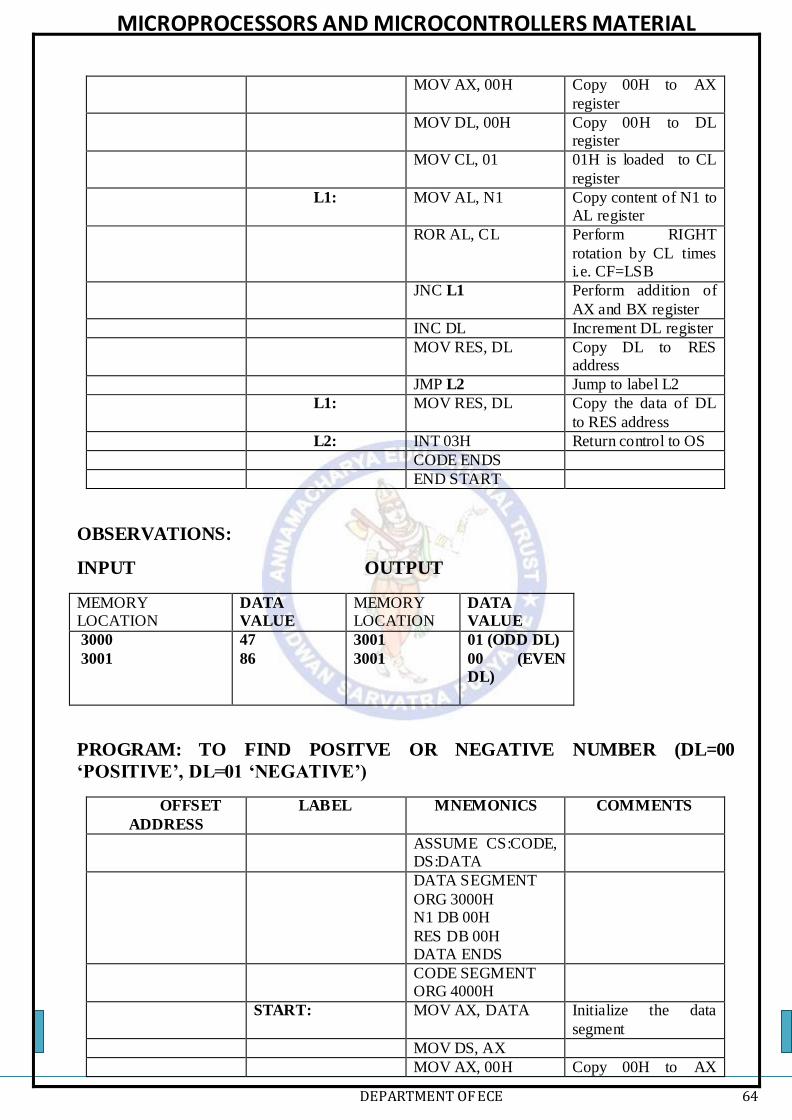
MICROPROCESSORS AND MICROCONTROLLERS MATERIAL
DEPARTMENT OF ECE 64
MOV AX, 00H Copy 00H to AX
register
MOV DL, 00H Copy 00H to DL register
MOV CL, 01 01H is loaded to CL
register
L1: MOV AL, N1 Copy content of N1 to AL register
ROR AL, CL Perform RIGHT
rotation by CL times i.e. CF=LSB
JNC L1 Perform addition of
AX and BX register
INC DL Increment DL register
MOV RES, DL Copy DL to RES address
JMP L2 Jump to label L2
L1: MOV RES, DL Copy the data of DL
to RES address
L2: INT 03H Return control to OS
CODE ENDS
END START
OBSERVATIONS:
INPUT OUTPUT
MEMORY LOCATION
DATA
VALUE
MEMORY LOCATION
DATA
VALUE
3000
3001
47
86
3001
3001
01 (ODD DL)
00 (EVEN
DL)
PROGRAM: TO FIND POSITVE OR NEGATIVE NUMBER (DL=00
‘POSITIVE’, DL=01 ‘NEGATIVE’)
OFFSET
ADDRESS
LABEL MNEMONICS COMMENTS
ASSUME CS:CODE, DS:DATA
DATA SEGMENT
ORG 3000H N1 DB 00H
RES DB 00H DATA ENDS
CODE SEGMENT ORG 4000H
START: MOV AX, DATA Initialize the data
segment
MOV DS, AX
MOV AX, 00H Copy 00H to AX

MICROPROCESSORS AND MICROCONTROLLERS MATERIAL
DEPARTMENT OF ECE 65
register
MOV DL, 00H Copy 00H to DL register
MOV CL, 01 01H is loaded to CL register
L1: MOV AL, N1 Copy content of N1 to
AL register
ROL AL, CL Perform LEFT rotation by CL times
i.e. CF=LSB
JNC L1 Perform addition of AX and BX register
INC DL Increment DL register
MOV RES, DL Copy DL to RES
address
JMP L2 Jump to label L2
L1: MOV RES, DL Copy the data of DL to RES address
L2: INT 03H Return control to OS
CODE ENDS
END START
OBSERVATIONS:
INPUT OUTPUT
MEMORY LOCATION
DATA
VALUE
MEMORY LOCATION
DATA
VALUE
3000
3001
95
28
3001
3001
01
(NEGATIVE
DL)
00
(POSITIVE
DL)
PROGRAM: GCD OF TW0 16-BIT NUMBERS
OFFSET
ADDRESS
LABEL MNEMONICS COMMENTS
ASSUME CS:CODE,
DS:DATA
DATA SEGMENT ORG 3000H N1 DW 00H
N2 DW 00H RES DW 00H
DATA ENDS
CODE SEGMENT ORG 4000H
START: MOV AX, DATA Initialize the data
segment

MICROPROCESSORS AND MICROCONTROLLERS MATERIAL
DEPARTMENT OF ECE 66
MOV DS, AX
MOV AX, N1 Copy N1 to AX register
MOV BX, N2 Copy N2 to BX register
AGAIN: CMP AX, BX Perform comparison
on AX and BX
JE EXIT
JB BIG Jump if below to label Big
ABOVE: MOV DX, 00H Copy 00H to DX
register
DIV BX Perform division with BX register
CMP DX, 00H Compare DX with
00H
JE EXIT Jump if equal i.e. ZF=1 to label Exit
MOV AX, DX Copy the contents of
DX to AX register
JMP AGAIN Jump to the label again
BIG: XCHG AX, BX Exchange the contents
of AX and BX
JMP ABOVE Jump to the label above
EXIT: MOV RES, BX Copy BX data to RES
address
INT 03H Return control to OS
CODE ENDS
END START
OBSERVATIONS:
INPUT OUTPUT
MEMORY LOCATION
DATA
VALUE
MEMORY LOCATION
DATA
VALUE
3000
3001
3002
3003
88
00
24
00
3004
3005
04
00
PROGRAM: FINDING THE 16 - BIT PRIME NUMBER
OFFSET
ADDRESS
LABEL MNEMONICS COMMENTS
ASSUME CS:CODE, DS:DATA
DATA SEGMENT
ORG 3000H
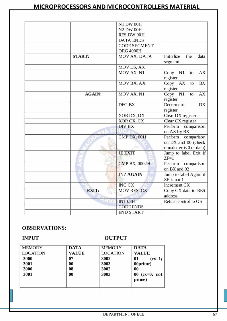
MICROPROCESSORS AND MICROCONTROLLERS MATERIAL
DEPARTMENT OF ECE 67
N1 DW 00H
N2 DW 00H RES DW 00H
DATA ENDS
CODE SEGMENT ORG 4000H
START: MOV AX, DATA Initialize the data
segment
MOV DS, AX
MOV AX, N1 Copy N1 to AX register
MOV BX, AX Copy AX to BX
register
AGAIN: MOV AX, N1 Copy N1 to AX register
DEC BX Decrement DX
register
XOR DX, DX Clear DX register
XOR CX, CX Clear CX register
DIV BX Perform comparison on AX by BX
CMP DX, 00H Perform comparison
on DX and 00 (check remainder is 0 or data)
JZ EXIT Jump to label Exit if ZF=1
CMP BX, 0002H Perform comparison
on BX and 02
JNZ AGAIN Jump to label Again if ZF is not 1
INC CX Increment CX
EXIT: MOV RES, CX Copy CX data to RES
address
INT 03H Return control to OS
CODE ENDS
END START
OBSERVATIONS:
INPUT OUTPUT
MEMORY
LOCATION
DATA
VALUE
MEMORY
LOCATION
DATA
VALUE
3000
3001
3000
3001
07
00
08
00
3002
3003
3002
3003
01 (cx=1;
00prime)
00
00 (cx=0; not
prime)

MICROPROCESSORS AND MICROCONTROLLERS MATERIAL
DEPARTMENT OF ECE 68