Embed Size (px)
Citation preview

ARMY TM 9-2815-254-24AIR FORCE TO 38G1-94-2
TECHNICAL MANUAL
UNIT, DIRECT SUPPORT ANDGENERAL SUPPORT MAINTENANCE INSTRUCTIONS
DIESEL ENGINEMODEL C-240PW-28
4 CYLINDER 2.4 LITERNSN: 2815-01-350-2207
HEADQUARTERS, DEPARTMENTS OF THE ARMY ANDTHE AIR FORCE
1 SEPTEMBER 1993


ARMY TM 9-2815-254-24AIR FORCE TO 38G1-94-2
SAFETY SUMMARY
For first aid, refer to FM21-11.
The noise level when operating could cause hearing damage. Earprotection must be worn.
Where applicable, prior to performing engine maintenance, ensure bat-teries are disconnected.
Do not drain coolant until the coolant temperature is below operatingtemperature. Always loosen cooling system filler cap, radiator cap, ordrain cock slowly to relieve any excess pressure.
Diesel fuel is flammable and toxic to eyes, skin, and respiratory tract.Skin/eye protection required. Avoid repeated/prolonged contact. Goodgeneral ventilation is normally adequate.
Cleaning solvent is flammable and toxic to eyes, skin, and respiratorytract. Skin/eye protection required. Avoid repeated/prolonged contact.Good general ventilation is normally adequate.
Compressed air used for cleaning can create airborne particles thatmay enter the eyes. Pressure will not exceed 30 psig (207 kPa). Eyeprotection required.
a/(b blank)


CHANGE
No.2
ARMY TM 9-2815-254-24AIR FORCE TO 38G1-94-2
C 2
HEADQUARTERS, DEPARTMENTS OFTHE ARMY AND THE AIR FORCE
WASHINGTON, D.C., 30 October 1996
Unit, Direct Support and GeneraI SupportMaintenance lnstructions
DIESEL ENGINEMODEL C-240PW-28
4 CYLINDER 2.4 LITERNSN: 2815-01-350-2207
DISTRIBUTION STATEMENT A: Approved for public release; distribution is unlimited
TM 9-2815-254-24/TO 38G1-94-2, 1 September 1993, is changed as follows:
1. Remove and insert pages as indicated below. New or changed text material is indicated by a vertical barin the margin. An illustration change is indicated by a miniature pointing hand.
Remove pagesi and ii3-1 and 3-23-35 and 3-363-69 through 3-763-79 through 3-823-85 through 3-863-91 through 3-963-147 through 3-1503-163 through 3-166
Insert pagesi and ii3-1 and 3-23-35, and 3-363-69 through 3-763-79 through 3-823-85 through 3-883-91 through 3-963-147 through 3-1503-163 through 3-166
2. Retain this sheet in front of manual for reference purposes.
ARMY TM 9-2815-254-24AIR FORCE TO 38G1-94-2
C 2
By Order of the Secretaries of the Army and Air Force:
Official:
DENNIS J. REIMERGeneral, United States Army
Chief of Staff
Administrative Assistant to theSecretary of the Army
02954
RONALD R. FOGELMANGeneral, USAFChief of Staff
HENRY VICCELLIO Jr.General, USAFCommander, Air Force Material Command
DISTRIBUTION:To be distributed in accordance with DA Form 12-25-E, block no. 5143, requirements for
TM 9-2815-254-24.

CHANGE
No. 1
ARMY TM 9-2815-254-24AIR FORCE TO 38G1-94-2
C1
HEADQUARTERSDEPARTMENTS OF THE ARMY, AND AIR FORCE
WASHINGTON, DC., 15 DECEMBER 1993
TECHNICAL MANUAL
UNIT, DIRECT SUPPORT AND GENERAL SUPPORTMAINTENANCE INSTRUCTIONS
DIESEL ENGINEMODEL C-240PW-28
4 CYLINDER 2.4 LITERNSN: 2815-01-350-2207
DISTRIBUTION STATEMENT A; Approved for public release; distribution is unlimited.
TM 9-2815-254-24/TO 39G1-94-2, 1 SEPTEMBER 1993 is changed as follows:
1. Remove and insert pages as indicated below. New or changed text material is indicated by a vertical barin the margin. An illustration change is indicated by a miniature pointing hand.
Remove pages lnsert pages
iii and iv iii and iiv3-3 and 3-4 3-3 and 3-43-9 through 3-12 3-9 through 3-12B-5 and B-6 B-5 and B-6- - - - - - Appendix E
2. Retain this sheet in front of manual for reference purposes.

ARMY TM 9-2815-254-24AIR FORCE TO 38G1-94-2
C 1
By Order of the Secretaries of the Army and air Force
MILTON H. HAMILTONAdministrative Assistant to the
Secretary of the Army05829
GORDON R. SULLIVANGeneral, United States Army
Chief of Staff
MERRILL A. McPEAKGeneral, USAFChief of staff
Official:
RONALD W. YATESGeneral, USAFCommander, Air Force Material Command
DISTRIBUTION:To be distributed in accordance with DA Fom 12-25-E, block no. 5143, requirements for
TM 9-2815-254-24.

ARMY TM 9-2815-254-24AIR FORCE TO 38G1-94-2
TECHNICAL MANUAL HEADQUARTERSDEPARTMENTS OF THE ARMY AND THE AIR FORCE
NO. 9-2815-254-24 WASHINGTON, D.C., 1 September 1993
Unit, Direct Support and General Support Maintenance Instructions
DIESEL ENGINEMODEL C-24OPW-284 CYLINDER 2.4 LITER
NSN: 2815-01-350-2207
REPORTING ERRORS AND RECOMMENDING IMPROVEMENTS
You can help improve this manual. If you find any mistakes or if you know of a way to improve theseprocedures, please let us know.
(A) Mail your letter or DA Form 2028 (Recommended Changes to Publications and Blank Forms), orDA Form 2028-2 located in the back of this manual directly to: Commander, US Army Aviation andTroop Command, ATTN: AMSAT-I-MP, 4300 Goodfellow Blvd., St. Louis, MO 63120-1798. You mayalso submit your recommended changes by E-mai l direct ly to < mpmt%[email protected]>. Instructions for sending an electronic 2028 may be found at the back of thispublication immediately preceding the hard copy 2028.
(F) Air Force - AFTO Form 22 Directly to: Commander, Sacramento Air Logistics Center, ATTN:TILBA, McClellan AFB, CA 95652-5990 (AFMC)
A reply will be furnished directly to you.
DISTRIBUTION STATEMENT A: Approved for public release; distribution is unlimited.
Chapter/Section/ParagraphTABLE OF CONTENTS
Chapter 1 INTRODUCTION . . . . . . . . . . . . . . . . . . . . . . . . . . . . . . . . . . . . . . . . . 1-1
Section I. GENERAL INFORMATION . . . . . . . . . . . . . . . . . . . . . . . . . . . . . . . . . 1-11-1. Scope. . . . . . . . . . . . . . . . . . . . . . . . . . . . . . . . . . . . . . . . . . . 1-11-2. Maintenance Forms, Records and Reports. . . . . . . . . . . . . . . . . . . . . 1-11-3. Reporting Equipment Improvement Recommendations (EIR). . . . . . . . . . 1-11-4. Destruction Of Army Materiel To Prevent Enemy Use. . . . . . . . . . . . . 1-21-5. Preparation For Storage Or Shipment. . . . . . . . . . . . . . . . . . . . . . . . 1-21-6. Warranty. . . . . . . . . . . . . . . . . . . . . . . . . . . . . . . . . . . . . . . . . 1-2
Section II. EQUIPMENT DESCRIPTION AND DATA . . . . . . . . . . . . . . . . . . . . . . . . 1-31-7. General. . . . . . . . . . . . . . . . . . . . . . . . . . . . . . . . . . . . . . . . . . 1-31-8. Detailed Description. . . . . . . . . . . . . . . . . . . . . . . . . . . . . . . . . . 1-31-9. Equipment Data. . . . . . . . . . . . . . . . . . . . . . . . . . . . . . . . . . . . . 1-5
Change 2 i

ARMY TM 9-2815-254-24AIR FORCE TO 38G1-94-2
TABLE OF CONTENTS - Continued
Section III. PREPARATION FOR USE . . . . . . . . . . . . . . . . . . . . . . . . . . . . . . . . 1-6
1-10 Inspecting and Servicing Engine. . . . . . . . . . . . . . . . . . . . . . . . . . 1-6
CHAPTER 2 OPERATION . . . . . . . . . . . . . . . . . . . . . . . . . . . . . . . . . . . . . . . . 2-1
Section I. PRINCIPLES OF OPERATION . . . . . . . . . . . . . . . . . . . . . . . . . . . . . . 2-1
2-1 Introduction. . . . . . . . . . . . . . . . . . . . . . . . . . . . . . . . . . . . . . 2-1
2-2 Cooling System. . . . . . . . . . . . . . . . . . . . . . . . . . . . . . . . . . . . 2-1
2-3 Lubrication System. . . . . . . . . . . . . . . . . . . . . . . . . . . . . . . . . . 2-1
2-4 Fuel System. . . . . . . . . . . . . . . . . . . . . . . . . . . . . . . . . . . . . . 2-1
2-5 Electrical System. . . . . . . . . . . . . . . . . . . . . . . . . . . . . . . . . . . 2-2
Section II. OPERATING INSTRUCTIONS. . . . . . . . . . . . . . . . . . . . . . . . . . . . . . 1-3
CHAPTER 3 MAINTENANCE . . . . . . . . . . . . . . . . . . . . . . . . . . . . . . . . . . . . . . 3-1
Section I. PREVENTIVE MAINTENANCE CHECKS AND SERVICES (PMCS) . . . . . . . . 3-1
3-1 PMCS Procedures. . . . . . . . . . . . . . . . . . . . . . . . . . . . . . . . . . . 3-1
Section II. TROUBLESHOOTING . . . . . . . . . . . . . . . . . . . . . . . . . . . . . . . . . . . 3-3
3-2 Troubleshooting Procedures. . . . . . . . . . . . . . . . . . . . . . . . . . . . 3-3
Section III. GENERAL MAINTENANCE . . . . . . . . . . . . . . . . . . . . . . . . . . . . . . 3-11
3-3 General. . . . . . . . . . . . . . . . . . . . . . . . . . . . . . . . . . . . . . . . 3-11
3-4 Disassembly and Assembly Sequence for Overhaul. . . . . . . . . . . . . 3-12
Section IV. COOLING SYSTEM MAINTENANCE . . . . . . . . . . . . . . . . . . . . . . . . 3-16
3-5 General. . . . . . . . . . . . . . . . . . . . . . . . . . . . . . . . . . . . . . . . 3-16
3-6 Thermostat. . . . . . . . . . . . . . . . . . . . . . . . . . . . . . . . . . . . . . 3-16
3-7 Water Pump. . . . . . . . . . . . . . . . . . . . . . . . . . . . . . . . . . . . . 3-18
Section V. FUEL SYSTEM MAINTENANCE . . . . . . . . . . . . . . . . . . . . . . . . . . . 3-21
3-8 General. . . . . . . . . . . . . . . . . . . . . . . . . . . . . . . . . . . . . . . . 3-21
3-9 Fuel Filter Assembly. . . . . . . . . . . . . . . . . . . . . . . . . . . . . . . . 3-21
3-10 Fuel Injectors and Piping. . . . . . . . . . . . . . . . . . . . . . . . . . . . . 3-24
3-11 Fuel Injection Pump. . . . . . . . . . . . . . . . . . . . . . . . . . . . . . . . 3-31
3-12 Bleeding and Priming Fuel System. . . . . . . . . . . . . . . . . . . . . . . 3-65
3-13 Fuel Injection Pump Timing. . . . . . . . . . . . . . . . . . . . . . . . . . . . 3-65
Section VI. LUBRICATION SYSTEM MAINTENANCE . . . . . . . . . . . . . . . . . . . . 3-69
3-14 Oil Filter. . . . . . . . . . . . . . . . . . . . . . . . . . . . . . . . . . . . . . . . 3-69
3-15 Oil Pressure Relief Valve . . . . . . . . . . . . . . . . . . . . . . . . . . . . . 3-70
3-16 Oil Piping . . . . . . . . . . . . . . . . . . . . . . . . . . . . . . . . . . . . . . 3-71
3-17 Oil Pan . . . . . . . . . . . . . . . . . . . . . . . . . . . . . . . . . . . . . . . . 3-73
3-18 Oil Pump . . . . . . . . . . . . . . . . . . . . . . . . . . . . . . . . . . . . . . . 3-75
3-19 Oil Pressure Test . . . . . . . . . . . . . . . . . . . . . . . . . . . . . . . . . . 3-76
Section VII. INTAKE AND EXHAUST SYSTEM MAINTENANCE . . . . . . . . . . . . . . . 3-79
3-20 PCV Assembly . . . . . . . . . . . . . . . . . . . . . . . . . . . . . . . . . . . 3-79
3-21 Intake and Exhaust Manifolds . . . . . . . . . . . . . . . . . . . . . . . . . . 3-82
Section VIII. ELECTRICAL SYSTEM . . . . . . . . . . . . . . . . . . . . . . . . . . . . . . . . . 3-85
3-22 Glow Plugs . . . . . . . . . . . . . . . . . . . . . . . . . . . . . . . . . . . . . 3-85
3-23 Starter Assembly . . . . . . . . . . . . . . . . . . . . . . . . . . . . . . . . . 3-85
3-24 Alternator . . . . . . . . . . . . . . . . . . . . . . . . . . . . . . . . . . . . . . 3-93
ii Change 2

ARMY TM 9-2815-254-24AIR FORCE TO 38G1-94-2
Section3-253-263-273-283-293-303-313-32
APPENDIX
APPENDIX
APPENDIX
References
APPENDIX
APPENDIX
lX.
A
B
C
D
E
TABLE OF CONTENTS - ContinuedENGINE BLOCK MAINTENANCE . . . . . . . . . . . . . . . . . . . . . . . . . . . . . . . . . . . . . . . . . . . . . 3 - 9 9Front Gear Cover . . . . . . . . . . . . . . . . . . . . . . . . . . . . . . . . . . . . . . . . . . . 3 - 9 9Rocker Cover and Arms. . . . . . . . . . . . . . . . . . . . . . . . . . . . . . . . . . . . . . . . . . . . . . . . . . . . 3-102Cylinder Head Assembly . . . . . . . . . . . . . . . . . . . . . . . . . . . . . . . . . . . . . . . . . . . . . . . . . . . . 3-110Pistons, Connecting Rods, and Crankshaft. . . . . . . . . . . . . . . . . . . . . . . . . . . . . . . . . . . . 3-127Crankcase . . . . . . . . . . . . . . . . . . . . . . . . . . . . . . . . . . . . . . . . . . . . . . . . . . . . . . . . . . . . . . . . 3-148Camshaft and ldler Gear Assemblies. . . . . . . . . . . . . . . . . . . . . . . . . . . . . . . . . . . . . . . . . 3-150Flywheel and Housing. . . . . . . . . . . . . . . . . . . . . . . . . . . . . . . . . . . . . . . . . . . . . . . . . . . . . . 3-158Cylinder Block Assembly . . . . . . . . . . . . . . . . . . . . . . . . . . . . . . . . . . . . . . . . . . . . . . . . . . . . 3-162
. . . . . . . . . . . . . . . . . . . . . . . . . . . . . . A-1
Maintenance Allocation Chart . . . . . . . . . . . . . . . . . . . . . . . . . . . . . B-1
Expendable/Durable Suppliesand Materials List (EDSML) . . . . . . . . . . . . . . . . . . . . . . . . . . . . . . . . . . . . . . . . . . . . . . . . . . C-1
Fabrication of Tools . . . . . . . . . . . . . . . . . . . . . . . . . . . . . . . . . . . . . . . . . . . . . . . . . . . . . D-1
Maintenance Procedures and Authorized Level Maintenance . . . . . . . . . . . . E-1
Alphabetical lndex . . . . . . . . . . . . . . . . . . . . . . . . . . . . . . . . . . . . . . . . . . . . . . . . . . . . . . . . . . . . . . . . . . . . . . . . . . . . . . . . . I-1
Change 1 i i i

ARMY TM 9-2815-254-24AIR FORCE TO 36G1-94-2
1-13-13-23-33-43-53-63-73-83-93-103-113-123-133-143-153-163-173-183-193-203-213-223-233-243-253-263-273-283-293-303-313-323-333-343-353-363-373-383-393-403-413-42
Engine Components. . . . . . . . . . . . . . . . . . . . . . . . . . . . . . . . . . . . . . . . . . . . . . . . . . . . 1-4
Thermostat and Housing. . . . . . . . . . . . . . . . . . . . . . . . . . . . . . . . . . . . . . . . . . . . . . . 3-16
Water Pump. . . . . . . . . . . . . . . . . . . . . . . . . . . . . . . . . . . . . . . . . . . . . . . . . . . . . . . . . . 3-20Fuel Filter Assembly. . . . . . . . . . . . . . . . . . . . . . . . . . . . . . . . . . . . . . . . . . . . . . . . . . . 3-23Fuel Injectors and Piping. . . . . . . . . . . . . . . . . . . . . . . . . . . . . . . . . . . . . . . . . . . . . . . 3-26Fuel Injector Spay Pattern. . . . . . . . . . . . . . . . . . . . . . . . . . . . . . . . . . . . . . . . . . . . . . 3-30Top Dead Center. . . . . . . . . . . . . . . . . . . . . . . . . . . . . . . . . . . . . . . . . . . . . . . . . . . . . . . 3-32Fuel Feed Pump and Timer Assembly. . . . . . . . . . . . . . . . . . . . . . . . . . . . . . . . . . . . . . 3-34Fuel Injection Pump Assembly. . . . . . . . . . . . . . . . . . . . . . . . . . . . . . . . . . . . . . . . . . . . 3-35Attaching Coupling (Typical). . . . . . . . . . . . . . . . . . . . . . . . . . . . . . . . . . . . . . . . . . . . . . 3-36lnserting Tappet Holder (Typical). . . . . . . . . . . . . . . . . . . . . . . . . . . . . . . . . . . . . . . . . . 3-36Removing screw Plug (Typical). . . . . . . . . . . . . . . . . . . . . . . . . . . . . . . . . . . . . . . . . . 3-37Removing coupling (Typical) . . . . . . . . . . . . . . . . . . . . . . . . . . . . . . . . . . . . . . . . . . . . . . . . . 3-37Removing Tappet Holder (Typical). . . . . . . . . . . . . . . . . . . . . . . . . . . . . . . . . . . . . . . . . . . . . 3-38Removing Tapped (Typical) . . . . . . . . . . . . . . . . . . . . . . . . . . . . . . . . . . . . . . . . . . . . . . . . . . . 3-39Removing Delivery Valve . . . . . . . . . . . . . . . . . . . . . . . . . . . . . . . . . . . . . . . . . . . . . . . . . . . . . 3-40Removing Plunger Barrel . . . . . . . . . . . . . . . . . . . . . . . . . . . . . . . . . . . . . . . . . . . . . . . . . . . . 3-41Plunger Helix.. . . . . . . . . . . . . . . . . . . . . . . . . . . . . . . . . . . . . . . . . . . . . . . . . . . . . . . . . . . . . . 3-43Checking Plunger and Barrel Movement . . . . . . . . . . . . . . . . . . . . . . . . . . . . . . . . . . . . . . . 3-44Delivery Valve . . . . . . . . . . . . . . . . . . . . . . . . . . . . . . . . . . . . . . . . . . . . . . . . . . . . . . . . . . . . . . 3-44Checking Plunger and Barrel for Damage 3-45. . . . . . . . . . . . . . . . . . . . . . . . . . . . . . . . . . . . . .Tappet . . . . . . . . . . . . . . . . . . . . . . . . . . . . . . . . . . . . . . . . . . . . . . . . . . . . . . . . . . . . . . . . . . . . . 3-45Lower Spring Seat . . . . . . . . . . . . . . . . . . . . . . . . . . . . . . . . . . . . . . . . . . . . . . . . . . . . . . . . . . 3-46Camshaft . . . . . . . . . . . . . . . . . . . . . . . . . . . . . . . . . . . . . . . . . . . . . . . . . . . . . . . . . . . . . . . . . . 3-46camshaft Bearings . . . . . . . . . . . . . . . . . . . . . . . . . . . . . . . . . . . . . . . . . . . . . . . . . . . . . . . . . . 3-47Bearing Removal . . . . . . . . . . . . . . . . . . . . . . . . . . . . . . . . . . . . . . . . . . . . . . . . . . . . . . . . . . . 3-47Feed Pump Tappet . . . . . . . . . . . . . . . . . . . . . . . . . . . . . . . . . . . . . . . . . . . . . . . . . . . . . . . . . . 3-48Feed Pump Plug . . . . . . . . . . . . . . . . . . . . . . . . . . . . . . . . . . . . . . . . . . . . . . . . . . . . . . . . . . . . 3-49Checking Sleeve Pinion Movement . . . . . . . . . . . . . . . . . . . . . . . . . . . . . . . . . . . . . . . . . . . . 3-51lnserting Plunger . . . . . . . . . . . . . . . . . . . . . . . . . . . . . . . . . . . . . . . . . . . . . . . . . . . . . . . . . . . . 3-51lnserting Tappet . . . . . . . . . . . . . . . . . . . . . . . . . . . . . . . . . . . . . . . . . . . . . . . . . . . . . . . . . . . . . 3-52Measuring Device Installed (Typical) . . . . . . . . . . . . . . . . . . . . . . . . . . . . . . . . . . . . . . . . . . . 3-55Feed Pump Test . . . . . . . . . . . . . . . . . . . . . . . . . . . . . . . . . . . . . . . . . . . . . . . . . . . . . . . . . . . . . 3-59Priming Pump Test . . . . . . . . . . . . . . . . . . . . . . . . . . . . . . . . . . . . . . . . . . . . . . . . . . . . . . . . . . 3-60Capacity Test . . . . . . . . . . . . . . . . . . . . . . . . . . . . . . . . . . . . . . . . . . . . . . . . . . . . . . . . . . . . . . . 3-61Feed Pump Pressure Test . . . . . . . . . . . . . . . . . . . . . . . . . . . . . . . . . . . . . . . . . . . . . . . . . . . . 3-62Air Tightness Test . . . . . . . . . . . . . . . . . . . . . . . . . . . . . . . . . . . . . . . . . . . . . . . . . . . . . . . . . . . 3-62RemovaI of Mechanical Governor . . . . . . . . . . . . . . . . . . . . . . . . . . . . . . . . . . . . . . . . . . . . . 3-64oil Filter . . . . . . . . . . . . . . . . . . . . . . . . . . . . . . . . . . . . . . . . . . . . . . . . . . . . . . . . . . . . . . . . . . . 3-70oil Piping . . . . . . . . . . . . . . . . . . . . . . . . . . . . . . . . . . . . . . . . . . . . . . . . . . . . . . . . . . . . . . . . . . 3-72Oil Pan Assembly . . . . . . . . . . . . . . . . . . . . . . . . . . . . . . . . . . . . . . . . . . . . . . . . . . . . . . . . . . . 3-73Oil Pump Assembly . . . . . . . . . . . . . . . . . . . . . . . . . . . . . . . . . . . . . . . . . . . . . . . . . . . . . . . . . 3-75Oil Pump Inspections . . . . . . . . . . . . . . . . . . . . . . . . . . . . . . . . . . . . . . . . . . . . . . . . . . . . . . . . 3-77
iv

ARMY TM 9-2815-254-24AIR FORCE TO 38G1-94-2
3-43 Oil Pressure Test Setup . . . . . . . . . . . . . . . . . . . . . . . . . . . . . . . . . . . . . . . . . . . . . . . . . . . . . . 3-78
3-44 PCV Assembly . . . . . . . . . . . . . . . . . . . . . . . . . . . . . . . . . . . . . . . . . . . . . . . . . . . . . . . . . . . . . 3-80
3-45 Intake and Exhaust Manifolds . . . . . . . . . . . . . . . . . . . . . . . . . . . . . . . . . . . . . . . . . . . . . . . . . 3-83
3-46 Glow Plugs Assembly . . . . . . . . . . . . . . . . . . . . . . . . . . . . . . . . . . . . . . . . . . . . . . . . . . . . . . . 3-86
3-47 Starter Assembly. . . . . . . . . . . . . . . . . . . . . . . . . . . . . . . . . . . . . . . . . . . . . . . . . . . . . . . . . . . . 3-88
3-48 Starter Solenoid Test Circuit . . . . . . . . . . . . . . . . . . . . . . . . . . . . . . . . . . . . . . . . . . . . . . . . . . 3-89
3-49 Alternator Assembly . . . . . . . . . . . . . . . . . . . . . . . . . . . . . . . . . . . . . . . . . . . . . . . . . . . . . . . . . 3-96
3-50 Front Gear Cover . . . . . . . . . . . . . . . . . . . . . . . . . . . . . . . . . . . . . . . . . . . . . . . . . . . . . . . . . . 3-100
3-51 Front Gear Cover Screw Tightening Sequence . . . . . . . . . . . . . . . . . . . . . . . . . . . . . . . . . 3-101
3-52 Rocker Cover and Arms . . . . . . . . . . . . . . . . . . . . . . . . . . . . . . . . . . . . . . . . . . . . . . . . . . . . . 3-103
3-53 Rocker Arm Retaining Plate Bolt Loosening Sequence . . . . . . . . . . . . . . . . . . . . . . . . . . 3-104
3-54 Rocker Arm Shaft Runout . . . . . . . . . . . . . . . . . . . . . . . . . . . . . . . . . . . . . . . . . . . . . . . . . . . 3-104
3-55 Rocker Arm Shaft Outside Diameter . . . . . . . . . . . . . . . . . . . . . . . . . . . . . . . . . . . . . . . . . . 3-105
3-56 Rocker Arm Oil Ports, Location of . . . . . . . . . . . . . . . . . . . . . . . . . . . . . . . . . . . . . . . . . . . . 3-106
3-57 Rocker Arm Correction . . . . . . . . . . . . . . . . . . . . . . . . . . . . . . . . . . . . . . . . . . . . . . . . . . . . . 3-107
3-58 Rocker Arm Retaining Plate Bolt Tightening Sequence . . . . . . . . . . . . . . . . . . . . . . . . . . 3-106
3-59 Valve clearance Adjustment Sequence . . . . . . . . . . . . . . . . . . . . . . . . . . . . . . . . . . . . . . . 3-109
3-60 Cylinder Head Assembly . . . . . . . . . . . . . . . . . . . . . . . . . . . . . . . . . . . . . . . . . . . . . . . . . . . . 3-111
3-61 Cylinder Head Bolt Loosening Sequence . . . . . . . . . . . . . . . . . . . . . . . . . . . . . . . . . . . . . . 3-1123-62 Hot Plug Removal . . . . . . . . . . . . . . . . . . . . . . . . . . . . . . . . . . . . . . . . . . . . . . . . . . . . . . . . . . 3-1133-63 Cylinder Head Inspection . . . . . . . . . . . . . . . . . . . . . . . . . . . . . . . . . . . . . . . . . . . . . . . . . . . 3-114
3-64 Cylinder Head Height (Reference) . . . . . . . . . . . . . . . . . . . . . . . . . . . . . . . . . . . . . . . . . . . . 3-115
3-65 Hot Plug Depression . . . . . . . . . . . . . . . . . . . . . . . . . . . . . . . . . . . . . . . . . . . . . . . . . . . . . . . 3-116
3-66 Valve Stem and Guide Clearance . . . . . . . . . . . . . . . . . . . . . . . . . . . . . . . . . . . . . . . . . . . . 3-117
3-67 Valve Stem Outside Diameter . . . . . . . . . . . . . . . . . . . . . . . . . . . . . . . . . . . . . . . . . . . . . . . . 3-117
3-68 Checking Valve Thickness . . . . . . . . . . . . . . . . . . . . . . . . . . . . . . . . . . . . . . . . . . . . . . . . . . 3-118
3-69 Valve Depression . . . . . . . . . . . . . . . . . . . . . . . . . . . . . . . . . . . . . . . . . . . . . . . . . . . . . . . . . . 3-118
3-70 Checking Valve Contact Width . . . . . . . . . . . . . . . . . . . . . . . . . . . . . . . . . . . . . . . . . . . . . . . 3-119
3-71 Valve Spring Free Height . . . . . . . . . . . . . . . . . . . . . . . . . . . . . . . . . . . . . . . . . . . . . . . . . . . . 3-1203-72 Valve Spring Tension . . . . . . . . . . . . . . . . . . . . . . . . . . . . . . . . . . . . . . . . . . . . . . . . . . . . . . . 3-120
3-73 Push Rod Curvature . . . . . . . . . . . . . . . . . . . . . . . . . . . . . . . . . . . . . . . . . . . . . . . . . . . . . . . . 3-121
3-74 Valve Seat Correction . . . . . . . . . . . . . . . . . . . . . . . . . . . . . . . . . . . . . . . . . . . . . . . . . . . . . . 3-122
3-75 Valve Seat Insert Installation . . . . . . . . . . . . . . . . . . . . . . . . . . . . . . . . . . . . . . . . . . . . . . . . . 3-123
3-76 Cylinder Head Bolt Tightening Sequence . . . . . . . . . . . . . . . . . . . . . . . . . . . . . . . . . . . . . . 3-126
3-77 Pistons, Connecting Rods, and Crankshaft . . . . . . . . . . . . . . . . . . . . . . . . . . . . . . . . . . . . 3-129
3-78 Crankshaft End Play . . . . . . . . . . . . . . . . . . . . . . . . . . . . . . . . . . . . . . . . . . . . . . . . . . . . . . . . 3-130
3-79 Crankshaft Bearing Cap Bolt Loosening Sequence . . . . . . . . . . . . . . . . . . . . . . . . . . . . . 3-130
3-80 Piston Ring and Groove Clearance . . . . . . . . . . . . . . . . . . . . . . . . . . . . . . . . . . . . . . . . . . . 3-132
3-81 Piston Ring . . . . . . . . . . . . . . . . . . . . . . . . . . . . . . . . . . . . . . . . . . . . . . . . . . . . . . . . . . . . . . . . 3-132
3-82 Measuring Piston Ring Gap . . . . . . . . . . . . . . . . . . . . . . . . . . . . . . . . . . . . . . . . . . . . . . . . . 3-133
3-83 Connecting Rod Side Face Clearance . . . . . . . . . . . . . . . . . . . . . . . . . . . . . . . . . . . . . . . . 3-134
3-84 Basic Dimension Measurements . . . . . . . . . . . . . . . . . . . . . . . . . . . . . . . . . . . . . . . . . . . . . 3-135
3-65 Crankshaft Run-out . . . . . . . . . . . . . . . . . . . . . . . . . . . . . . . . . . . . . . . . . . . . . . . . . . . . . . . . 3-136
3-66 Bearing Spread Measurement . . . . . . . . . . . . . . . . . . . . . . . . . . . . . . . . . . . . . . . . . . . . . . . 3-136
LIST OF ILLUSTRATIONS - Continued
v

ARMY TM 9-2815-254-24AIR FORCE TO 33G1-94-2
3-873-883-893-903-913-923-933-943-953-963-973-983-993-1003-1013-1023-1033-1043-1053-1063-1073-1083-1093-1103-1113-1123-1133-1143-1153-116
D-1 Fuel Injection Pump Tappet Holder . . . . . . . . . . . . . . . . . . . . . . . . . . . . . . . . . . . . . . . . . . . . . D-1
LIST OF ILLUSTRATIONS - ContinuedPage
Crankshaft Journal and Crankpin Diameter 3-137. . . . . . . . . . . . . . . . . . . . . . . . . . . . . . . . . . . .
Crankshaft Journal and Bearing Clearance . . . . . . . . . . . . . . . . . . . . . . . . . . . . . . . . . . . . 3-138
Connecting Rod Bearing Inside Diameter . . . . . . . . . . . . . . . . . . . . . . . . . . . . . . . . . . . . . 3-138
Crankhaft Journal and Bearing Clearance . . . . . . . . . . . . . . . . . . . . . . . . . . . . . . . . . . . . 3-139
comparing Bearing Gage . . . . . . . . . . . . . . . . . . . . . . . . . . . . . . . . . . . . . . . . . . . . . . . . . . . 3-140Crankshaft Gear lnstallation . . . . . . . . . . . . . . . . . . . . . . . . . . . . . . . . . . . . . . . . . . . . . . . . . 3-141Piston Ring Installation . . . . . . . . . . . . . . . . . . . . . . . . . . . . . . . . . . . . . . . . . . . . . . . . . . . . . 3-143Crankshaft Bearing Location . . . . . . . . . . . . . . . . . . . . . . . . . . . . . . . . . . . . . . . . . . . . . . . . . 3-144Crankshaft Bearing Cap Bolt Tightening Sequence . . . . . . . . . . . . . . . . . . . . . . . . . . . . 3-145Crankshaft Rear Oil Seal and Spacer . . . . . . . . . . . . . . . . . . . . . . . . . . . . . . . . . . . . . . . . 3-146
Piston Ring Gap Setting . . . . . . . . . . . . . . . . . . . . . . . . . . . . . . . . . . . . . . . . . . . . . . . . . . . . 3-147
Crankcase . . . . . . . . . . . . . . . . . . . . . . . . . . . . . . . . . . . . . . . . . . . . . . . . . . . . . . . . . . . . . . . . 3-149Crankcase Fastener Tightening Sequence . . . . . . . . . . . . . . . . . . . . . . . . . . . . . . . . . . . . 3-150Measuring Timing Gear Backlash . . . . . . . . . . . . . . . . . . . . . . . . . . . . . . . . . . . . . . . . . . . . 3-151
Camshaft and Idler Gear Assemblies . . . . . . . . . . . . . . . . . . . . . . . . . . . . . . . . . . . . . . . . . 3-152Thrust Plate Removal.. . . . . . . . . . . . . . . . . . . . . . . . . . . . . . . . . . . . . . . . . . . . . . . . . . . . . .ldler Gear Shaft Outside Diameter . . . . . . . . . . . . . . . . . . . . . . . . . . . . . . . . . 3-154
3-153
Camshaft Journal Diameter . . . . . . . . . . . . . . . . . . . . . . . . . . . . . . . . . . . . . 3-155Cam Height . . . . . . . . . . . . . . . . . . . . . . . . . . . . . . . . . . . . . . . . . . . . . . . . . . . . . . . . . . . . . . . 3-155
Camshaft Runout . . . . . . . . . . . . . . . . . . . . . . . . . . . . . . . . . . . . . . . . . . . . . . . . . . . . . . . . . .
Flywheel and Housing . . . . . . . . . . . . . . . . . . . . . . . . . . . . . . . . . . . . . . . . . . . . . . . . . . . . . .3-1563-159
Flywheel Bolt Loosening Sequence . . . . . . . . . . . . . . . . . . . . . . . . . . . . . . . . . . . . . . . . . . 3-160Flywheel Housing Installation Sequence . . . . . . . . . . . . . . . . . . . . . . . . . . . . . . . . . . . . . . 3-161
Flywheel Bolt Tightening Sequence . . . . . . . . . . . . . . . . . . . . . . . . . . . . . . . . . . . . . . . . . . 3-162Cylinder Block assembly . . . . . . . . . . . . . . . . . . . . . . . . . . . . . . . . . . . . . . . . . . . . . . . . . . . . 3-164Cylinder Block Upper Face Warpage Measurement . . . . . . . . . . . . . . . . . . . . . . . . . . . . . 3-166Cylinder Block Height Measurement . . . . . . . . . . . . . . . . . . . . . . . . . . . . . . . . . . . . . . . . . . 3-166Cylinder Liner Bore Measurement . . . . . . . . . . . . . . . . . . . . . . . . . . . . . . . . . . . . . . . . . . . . 3-168Cylinder Liner Installation . . . . . . . . . . . . . . . . . . . . . . . . . . . . . . . . . . . . . . . . . . . . . . . . .Press ing Cy l inder L iner
3-170. . . . . . . . . . . . . . . . . . . . . . . . . . . . . . . . . . . . . . . . . . . . . . . . 3-171
vi

ARMY TM 9-2815-254-24AIR FORCE TO 38G1-94-2
LIST OF TABLES
1-1 Table of Specifications . . . . . . . . . . . . . . . . . . . . . . . . . . . . . . . . . . . . . . . . . . . . . . . . . . . . . . . 1-5
3-1 Preventive Maintenance Checks and Services (PMCS) . . . . . . . . . . . . . . . . . . . . . . . . . . . . 3-1
3-2 Troubleshooting . . . . . . . . . . . . . . . . . . . . . . . . . . . . . . . . . . . . . . . . . . . . . . . . . . . . . . . . . . . . . . 3-4
3-3 Fuel Pump Test Specifications . . . . . . . . . . . . . . . . . . . . . . . . . . . . . . . . . . . . . . . . . . . . . . . . 3-56
3-4 Capacity Test . . . . . . . . . . . . . . . . . . . . . . . . . . . . . . . . . . . . . . . . . . . . . . . . . . . . . . . . . . . . . . . . 3-61
viii(viii blank)

ARMY TM 9-2815-254-24AIR FORCE TO 38G1-94-2
1-1.
1-1.1.
1-1.2.
1-2.
1-2.1.
1-2.2.
1-2.3.
1-3.
1-3.1.
1-3.2. Air Force. Air Force personnel are encouraged to submit EIR’s in accordance with AFR 900-4.
CHAPTER 1INTRODUCTION
SECTION I. GENERAL INFORMATION
SCOPE.
Type of Manual. This manual contains unit, direct support, and general support maintenance instructions for theModel C240 Diesel Engine, hereafter referred to as engine. Also included are descriptions of major systems/corn-ponents and their functions in relation to other systems/components.
Purpose of Equipment. The engine provides a driving force for generators or other equipment requiring this size(HP rating) and compatibility.
MAINTENANCE FORMS RECORDS AND REPORTS.
Reports of Maintenance Unsatisfactory Equipment. Department of the Army forms and procedures used forequipment maintenance will be those prescribed by DA Pam 738-750, the Army Maintenance Management Sys-tem (TAMMS). Air Force personnel will use AFR 66-1, Air Force Maintenance Management Policy, for mainte-nance reporting and TO-00-35D54 for unsatisfactory equipment reporting.
Reporting of Item and Packaging Discrepancies. Fill out and forward SF 364 (Report of Discrepancy (ROD)) asprescribed in AR 735-11-2/DLAR 414-55/SECNAVINST 4355.18/AFR 400-54/MCO 4430.3J.
Transportation Discrepancy Report (TDR) (SF 361). Fill out and forward Transportation Discrepancy Report(TDR) (SF 331) as prescribed in AR 55-38/NAVSUPINST 4610.33C/AFR 75-18/MCO P4610.19D/DLAR4500.15.
REPORTING EQUIPMENT IMPROVEMENT RECOMMENDATIONS (EIR).
Army. If your Military Standard Engine needs improvement, let us know. Send us an EIR. You, the user, are theonly one who car tell us what you don’t like about your equipment. Let us know why you don’t like the design orperformance. Put it on an SF 368 (Product Quality Deficiency Report). Mail it to us at: Commander, US. ArmyAviation and Troop Command, ATTN: AMSAT-I-MDO, 4300 Goodfellow Boulevard, St. Louis, Missouri63120-1798. We will send you a reply.
1-1

ARMY TM 9-2815-254-24AIR FORCE TO 38G1-94-2
1-4.
1-5.
1-6.
DESTRUCTION OF ARMY MATERIAL TO PREVENT USE.
Refer to TM 750-244-3 for procedures to destroy equipment to prevent enemy use.
Refer to TB 740-97-2 for procedures to place the equipment into storage.
WARRANTY.
The engine is warranted for a specific period of time. Refer to Warranty Technical Bulletin for the end item. Thewarranty starts on the date found in block 23, DA Form 2408-9, in the equipment log book. Report all defects inmaterial or workmanship to your supervisor, who will take appropriate action.
1-2

ARMY TM 9-2815-254-24AIR FORCE TO 38G1-94-2
SECTION II. EQUIPMENT DESCRIPTION AND DATA
1-7. GENERAL.
The diesel engine (FIGURE 1-1) is four cylinder, four cycle, fuel injected, naturally-aspirated, and liquid-cooled.The firing order is 1-3-4-2. The number one cylinder is toward the fan end of the engine. The serial number is foundon left side of the cylinder body at number one cylinder location. Rotation of engine is counterclockwise as viewedfrom flywheel.
NOTE
All locations referenced herein are given facing the flywheel end (rear)of the engine.
1-8. DETAILED DESCRIPTION.
1-8.1. Cooling System. The cooling system consists of a radiator, water pump, cooling fan, thermostat, and connectinghoses. The fan is mounted on shaft of water pump and both are belt driven from the crankshaft pulley. The thermo-stat controls engine temperature and is installed in the top of engine. The function of the cooling system is to main-tain a specific operating temperature of 180° to 203°F (82° to 95°C) for the engine.
1-8.2. Lubrication System. The lubrication system consists of the oil pan, a gerotor type oil pump, spin-on type oil filter,and internal passages within the engine. There are two external oil lines, one for rocker arm lubrication and onefor fuel injector pump lubrication.
1-8.3. Fuel System. The function of the fuel system is to inject a metered quantity of clean atomized fuel into the enginecylinders at a precise time near the end of the compression stroke of each piston. The fuel system consists ofthe fuel tank, fuel filter/water separator, fuel injection pump, and the fuel injectors. The fuel tank and fuel filter/wa-ter separator are not mounted on engine. The injection pump is mounted on the front cover and is driven by thetiming gears.
1-8.4. Electrical System. The electrical system is 24 VDC operation and consists of an alternator, starter, externallymounted batter and other items as required. The alternator is mounted on front of engine and is belt driven.When the engine is operating, the alternator supplies 24 VDC to recharge the battery and maintain it at a full stateof charge. The starter is mounted on the flywheel housing and when energized engages the ring gear of the fly-wheel to rotate the engine.
1-3

ARMY TM 9-2815-254-24AIR FORCE TO 38G1-94-2
1.2.3.4.5.6.7.8.9.
10.11.12.13.14.15.16.17.18.19.20.21.22.
FanFan BeltFan PulleyFuel PipesFuel Injector PipesInjector Nozzle and Glow PlugOil FilterFuel Filter HousingPCV ValveCrankshaft PulleyBattery Charging AlternatorStarterIntake ManifoldExhaust ManifoldValve coverThermostat HousingWater PumpOil PanFlywheel HousingCrankcaseFuel Injection PumpDipstick and Tube
FIGURE 1-1. Engine Components
1-4

ARMY TM 9-2815-254-24AIR FORCE TO 38G1-94-2
1-9. EQUlPMENT DATA.
1-9.1. Leading Particulars. For a list of leading particulars, refer to TABLE 1-1.
TABLE 1-1. Table of SpecificationsModel . . . . . . . . . . . . . . . . . . . . . . . . . . . . . . . . . . . . . . . . . . . . . . . . . . . . . . . . . . . . . lsuzu, C240 PW-28Type . . . . . . . . . . . . . . . . . . . . . . . . . . . . . . . . . . . . . . . . . Four cylinder, four cycle, liquid cooled dieselBore/Stroke . . . . . . . . . . . . . . . . . . . . . . . . . . . . . . . . . . . . . . . . . . . . . . . . . . . 3.38/4.01 in. (86/102 mm)DisplacementHorsepower Rating ...............................................................................
144.5 cu in. (2369 cu cm)32 BHP @ 1800 rpm
Compression Ratio . . . . . . . . . . . . . . . . . . . . . . . . . . . . . . . . . . . . . . . . . . . . . . . . . . . . . . . . . . 20:1Length
.....................................................................................................28.9 in (736 mm)
Width 21.0 in (535 mm)HeightWeight
32.1 in (815 mm)491 Ibs (223 kg)
Firing Order...................................................................................................................Injection Pump
1-3-4-2Kiki - PES4A
Governor . . . . . . . . . . . . . . . . . . . . . . . . . . . . . . . . . . . . . . . . . . . Barber-Colman Model 10502-001-0-2Injection Starting Pressure . . . . . . . . . . . . . . . . . . . . . . . . . . . . . . . . . . . . . . . . . . 1706 psi (11,772 kPa)Cylinder Compression Pressure (warm) . . . . . . . . . . . . . . . . . . . . . . . . . . . . . . . . . 441 psi (3041 kPa)Valve Clearance (cold) . . . . . . . . . . . . . . . . . . . . . . . . . . . . . . . . . . . . . . . . . . . . . . . . 0.017 in. (0.45 mm)Lubrication System Capacity . . . . . . . . . . . . . . . . . . . . . . . . . . . . . . . . . . . . . . . . . . . . 1.6 gal (6.1 liters)Coolant System Capacity (engine only) 1.37 gal (5.2 liters)Battery Charging Alternator. . . . . . . . . . . . . . . . . . . . . . . . . . . . . . . . . . . . . . . .
. . . . . . . . . . . . . . . . . . . . . . . . . . . . . . . . . . . . . . . . . . . . .Hitachi, 24 VDC - 20 amp
S t a r t e r . . . . . . . . . . . . . . . . . . . . . . . . . . . . . . . . . . . . . . . . . . . . . . . . . . . . . . . . . . H i t a c h i , 2 4 V D C - 3 . 5 k w
1-5

ARMY TM 9-2815-254-24AIR FORCE TO 38G1-94-2
SECTION III. PREPARATION FOR USE
1-10. lNSPECTlNG AND SERVlCING ENGINE.
This section provides information and guidance for inspecting, servicing, and installing the engine. For additionalinformation, also refer to end item maintenance manual.
1-10.1. Inspection.
a. Check that all packing materials have been removed.
b. Check engine identification plate for positive identification.
c. Inspect engine exterior for shipping damage.
d. Check fan belt drive for proper tension. Refer to end item maintenance manual.
e. Inspect engine for loose or missing mounting hardware, or damaged or missing parts.
1-10.2. Service. Except for servicing the lubrication system all other servicing must be accomplished after engine ismounted in the end item, refer to end item maintenance manual and lubrication order (LO).
1-6

ARMY TM 9-2815-254-24AIR FORCE TO 38G1-94-2
CHAPTER 2
OPERATION
SECTION I. PRINCIPLES OF OPERATION
2-1. INTRODUCTIONS
This section contains functional descriptions of the engine systems and how they are connected to the end item
2-2. COOLING SYSTEM.
The cooling system consists of a radiator, hoses, thermostat, belt driven fan, water pump, and cooling jacketswithin the engine. The water pump forces coolant through passages (coolant jackets) in the engine block andcylinder head where coolant absorbs heat from the engine. When the coolant temperature is below operating tem-perature, the thermostat is closed and coolant is bypassed to the water pump inlet. As coolant temperature in-creases to 180°F (82°C), the thermostat starts to open, restricting bypass flow and opening flow to the radiator. Ascoolant temperature continues to increase to 203°F (95°C), the thermostat is fully opened, shutting off all bypassflow and providing full flow through the radiator. Air forced through the fins of the radiator by the fan cools thecoolant pumped through the radiator. Items are added to the engine to monitor coolant temperature and to warn iftemperature exceeds a predetermined value.
2-3. LUBRICATION SYSTEM.
The lubrication system consists of an oil pan, dipstick, pump, and filter. The oil sump is a reservoir for lubricatingoil. The dipstick indicates oil level in sump. The pump draws oil from the sump through a screen which removeslarge impurities. The oil then passes through a spin-on type filter where small impurities are removed. From thefilter, oil enters the cylinder head oil gallery and is distributed to the engines internal moving parts and to the fuelinjection pump. After passing through the block and pump, the oil returns to the oil sump. Items are added to moni-tor oil pressure and to warn/stop engine if pressure drops to a dangerously low value.
2-4. FUEL SYSTEM.
2-4.1. The fuel system consists of an external fuel tank, transfer pump, fuel filter/water separator, fuel injection pump,fuel injectors, and piping. Fuel from an external source is supplied to the fuel injection pump. The injection pumpprovides a pressurized metered quantity of clean atomized fuel through the injector nozzles into the cylinder ata precise time near the end of the compression stroke of each piston. The fuel that is not used by the injectorsis returned to the fuel tank via an excess fuel return line.
2-1

ARMY TM 9-2815-254-24AIR FORCE TO 38G1-94-2
2-4.2. Extremely cold outside temperatures make starting the engine difficult. To improve engine starting, a cold weatherstarting aid has been provided that features a glow plug for each cylinder. The glow plugs are energized to preheatengine combustion air during engine preheat starting cycle.
2-5. ELECTRICAL SYSTEM.
The electrical system consists of external mounted batteries, starter, battery charging alternator, and related re-lays and switches for control of the system. Battery power supplied to the starter during the start cycle energizesthe starter which engages the ring gear of the flywheel causing the engine to turn over. When engine start is com-plete, the starter is deenergized and disengages from the flywheel. The battery charging alternator is belt driven. Itis a 20 ampere, 24 VDC alternator that when operating, supplies voltage to the 24 VDC circuit and recharges thebatteries and maintains them at a full state of charge.
2-2

ARMY TM 9-2815-254-24AIR FORCE TO 38G1-94-2
SECTION II. OPERATING INSTRUCTIONS
NOTE
Refer to end item operator’s manual.
2-3/(2-4 blank)


ARMY TM 9-2815-254-24AIR FORCE TO 38G1-94-2
CHAPTER 3
MAINTENANCE
Section I. PREVENTIVE MAINTENANCE CHECKS AND SERVICES (PMCS)
3-1. PMCS PROCEDURES.
3-1.1. General.
To ensure that engine is ready for operation at all times, it must be inspected so defects can be discoveredand corrected before they result in serious damage or failure. Perform operator’s PMCS prior to or inconjunction with performance of engine PMCS. For engine PMCS, refer to TABLE 3-1.
Table 3-1. Preventive Maintenance Checks and Services (PMCS)
Item Interval Procedures Check Equipment isNo. Item for and have Not/Ready
M Q S A B H to be repaired or adjusted AvailableInspected as necessary If:
1 300 Oil Filter Change oil filter.Refer to paragraph3-14.1.
NOTE
Oil filter change interval is a hard timereplacement to beused when AOAPlab is not available.
2 750 PCV System Service PCV system.Refer to paragraph3-20.
3 1500 Cylinder Head Torque cylinder headBolts bolts. Refer to
paragraph 3-27.6d.
4 3000 Engine ValveClearances
NOTE
Valve clearancemust be checkedafter cylinder headbolt tightening hasbeen done. Refer tostep 3 in this table.
Adjust engine valveclearances. Refer toparagraph 3-26.6.
Change 2 3-1

ARMY TM 9-2815-284-24AIR FORCE TO 38G1-94-2
Table 3-1. Preventive Maintenance Checks and Services (PMCS) - Continued
Item Interval Procedures Check Equipment isNo. Item for and have Not/Ready
M Q S A B H to be repaired or adjusted AvailableInspected as necessary If:
5 3000 Engine Fuel Remove, clean, andInjectors test injectors. Refer
to paragraph 3-10.
6 1500 EngineCompression
Check engine com-pression. Refer toparagraph 3-27.7.
Engine compressionis low.
7 1500 Engine OilPressure
Check engine oilpressure. Refer toparagraph 3-19.
Engine oil pressurenot as specified.
6 300 Fuel Injection Remove oil levelPump Governor plug to check oilOil level. Fill at fill plug.
Change oil if itbecomes con-taminated.
3-2 Change 2

ARMY TM 9-2815-254-24AIR FORCE TO 38G1-94-2
SECTION II. TROUBLESHOOTlNG
3-2. TROUBLESHOOTING PROCEDURES.
3-2.1. Purpose of Troubleshooting Table. This section contains troubleshooting information for locating and Correcting
operating troubles which may develop in the engine. Each malfunction for an individual component unit or systemis followed by a list of tests or inspections which will help you to determine probable causes and corrective actionto take. You should perform tests/inspections and corrective actions in order listed.
This table cannot list all malfunctions that may occur, nor all tests or inspections and corrective actions. If a mal-function is not listed or cannot be corrected by listed corrective actions. notify your supervisor.
NOTE
Before you use this table, be sure you have performed your PMCS.Prior to performing troubleshooting procedures within this manual, per-form your operator’s troubleshooting and the end item maintenancemanual troubleshooting procedures.
SYMPTOM INDEX
Malfunction
Engine Will Not CrankStarter Operates But Engine Does Not Turn OverEngine Cranks But Fails To StartEngine Hard To Start or WiII Not Start
In Cold WeatherEngine Misfires or Runs Irregularly or
Stalls FrequentlyEngine Does Not Develop Full PowerEngine OverheatingExcessive Oil ConsumptionLow Oil PressureExcessive Fuel ConsumptionBlack or Gray SmokeBlue Exhaust SmokeEngine KnocksEngine Makes Abnormal NoiseEngine Makes a Gas Leaking NoiseDetonation or Pre-IgnitionBattery Charge Ammeter Shows No Charge
When Batteries Are LowBattery Charge Ammeter Shows Excessive
Charging After Prolonged Period
TroubleshootingProcedures Page
3-43-43-4
3-5
3-53-63-63-63-73-73-83-83-93-93-103-10
3-10
3-11
Change 1 3-3

ARMY TM 9-2815-254-24AIR FORCE TO 38G1-94-2
TABLE 3-2 Troubleshooting
1. ENGINE WILL NOT CRANK
Step 1. Check for defective end item starting system.
Troubleshooting per end item maintenance manual. lf not defective, do step 2.
Step 2. Check for defective starter motor and solenoid.
a Test starter and solenoid. Refer to paragraph NO TAG
b. Repair/replace defective starter and/or solenoid. Refer to paragraph 3-23.
2. STARTER OPERATES BUT ENGINE DOES NOT TURN OVER.Step 1. Check for worn or broken starter pinion gear and/or flywheel ring gear.
a . Remove starter and inspect pinion gear and flywheel ring gear for damage.b . Replace defective clutch assembly and/or flywheel ring gear. Refer to paragraphs 3-23 and
3-31.
Step 2. Crankshaft rotation restricted. Attempt to manually rotate engine. If unable to manually rotate,repair/replace engine.
3 . ENGINE CRANKS BUT FAILS TO STARTStep 1.
Step 2.
Step 3.
Step 4.
Step 5.
Step 6.
Check for fuel being supplied to fuel injection pump.a . Test feed pump capacity. Refer to paragraph NO TAG. If feed pump not defec-
tive, do step 2.
b. Repair or replace fuel feed pump. Refer to paragraph 3-11.
Check for dogged fuel filter/water separator.
a Remove and dean fuel filter Assembly, paragraph 3-9. If dean, replace water separator, re-fer to end item maintenance manual.
Check for air in fuel system lines.
Bleed fuel system. Refer to paragraph 3-12. If fuel system is free air, do step 4.
Check for fuel injector starling pressure too Iow or spray condition improper.
a Remove, dean and test fuel injector. Refer to paragraph 3-10. Adjust as necessary, if injectorcan not be adjusted, go to b. If not defective, do step 5.
b. Replace fuel injector. Refer to paragraph 3-10.
Check for improper fuel inject pump timing.
a. Check fuel injection pump timing. Refer to paragraph 3-13.1. If fuel injection pump timing iscorrect, do step 6.
b. Adjust fuel injection pump timing. Refer to paragraph 3-132.
Check for defective fuel injection pump.
a. Remove and test fuel injection pump. Refer to paragraph NO TAG.
b. Repair or replace defective fuel injection pump. Refer to paragraph 3-11.
3-4

ARMY TM 9-2815-254-24AIR FORCE TO 38G1-94-2
Table 3-2. Troubleshooting - Continued
MALFUNCTIONTEST OR INSPECTION
CORRECTIVE ACTION
4. ENGINE HARD TO START OR WILL NOT START IN COLD WEATHER.
step 1. Check for faulty glow plugs.
a. Test glow plugs. Refer to paragraph 3-22.3. If glow plugs not defective, do step 2.
b. Replace defective glow plugs. Refer to paragraph 3-22.
Step 2. Refer to Malfunction 3 and perform steps 1 through 5.
5. ENGINE MISFIRES OR RUNS IRREGULARLY OR STALLS FREQUENTLY.
Step 1.
Step 2.
Step 3.
Step 4.
step 5.
Step 6.
step 7.
Check for fuel being supplied to fuel injection pump.
a. Test feed pump capacity. Refer to paragraph 3-11.5 step aj. If feed pump not defective, dostep 2.
b. Repair or replace fuel feed pump. Refer to paragraph 3-11.
Check for air in fuel system lines.
Bleed fuel system at fuel fitter. Refer to paragraph 3-12. If no air, do step 3.
Check for tow coolant temperature.
a. If coolant temperature not low, do step 4.
b. Replace defective thermostat. Refer to paragraph 3-6.
Check for fuel injector nozzle dirty, defective or leaking.
a. Clean and test fuel injector. Refer to paragraph 3-10. If not defective, do step 5.
b. Replace fuel injector nozzle. Refer to paragraph 3-10.
Check for improper fuel injection timing.
a. Check fuel injection timing. Refer to paragraph 3-13.1. If fuel injection timing is correct, dostep 6.
b. Adjust fuel injection timing. Refer to paragraph 3-13.2.
Check for defective fuel injection pump.
a. Remove and test fuel injection pump. Refer to paragraph 3-11.5. If not defective, do step 7.
b. Replace fuel injection pump. Refer to paragraph 3-11.
Check for valves improperly adjusted.
a. Adjust valves. Refer to paragraph 3-26.6. if properly adjusted, do step 8.
3-5
ARMY TM 9-2815-254-24AIR FORCE TO 38G1-94-2
Table 3-2. Troubleshooting - Continued
MALFUNCTIONTEST OR INSPECTION
CORRECTIVE ACTION
Step 8. Check for low engine compression.
a. Perform engine compression check. Refer to paragraph 3-27.7.
b. If engine defective, repair or replace engine.
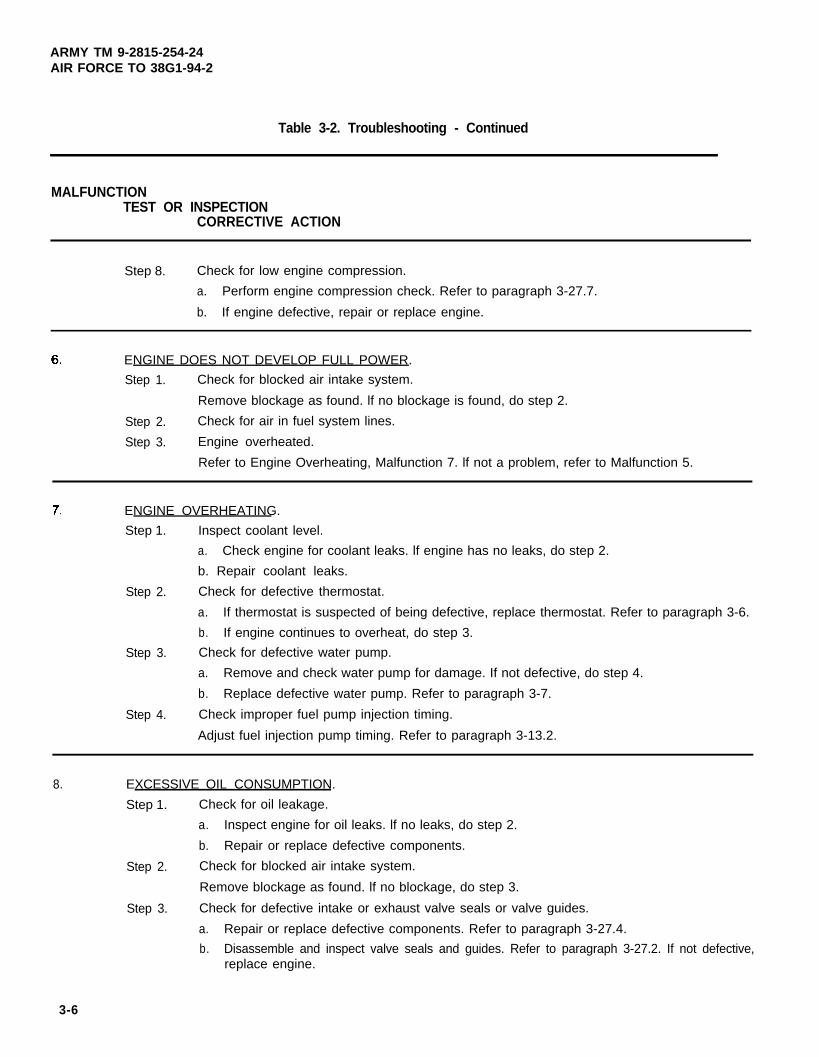
ENGINE DOES NOT DEVELOP FULL POWER.
Step 1. Check for blocked air intake system.
Remove blockage as found. lf no blockage is found, do step 2.
Step 2. Check for air in fuel system lines.
Step 3. Engine overheated.
Refer to Engine Overheating, Malfunction 7. lf not a problem, refer to Malfunction 5.
ENGINE OVERHEATING.
Step 1.
Step 2.
Step 3.
Step 4.
Inspect coolant level.
a. Check engine for coolant leaks. lf engine has no leaks, do step 2.
b. Repair coolant leaks.
Check for defective thermostat.
a. If thermostat is suspected of being defective, replace thermostat. Refer to paragraph 3-6.
b. If engine continues to overheat, do step 3.
Check for defective water pump.
a. Remove and check water pump for damage. If not defective, do step 4.
b. Replace defective water pump. Refer to paragraph 3-7.
Check improper fuel pump injection timing.
Adjust fuel injection pump timing. Refer to paragraph 3-13.2.
8. EXCESSIVE OIL CONSUMPTION.
Step 1. Check for oil leakage.
a. Inspect engine for oil leaks. lf no leaks, do step 2.
b. Repair or replace defective components.
Step 2. Check for blocked air intake system.
Remove blockage as found. lf no blockage, do step 3.
Step 3. Check for defective intake or exhaust valve seals or valve guides.
a. Repair or replace defective components. Refer to paragraph 3-27.4.
b. Disassemble and inspect valve seals and guides. Refer to paragraph 3-27.2. If not defective,replace engine.
3-6

ARMY TM 9-2815-254-24AIR FORCE TO 38G1-94-2
Table 3-2. Troubleshooting - Continued
MALFUNCTIONTEST OR INSPECTION
CORRECTIVE ACTION
9. LOW OIL PRESSURE.
Step 1. Check for improper grade of oil.
a. Refer to end item lubrication order. If proper grade of oil, do step 2.
b. If improper grade of oil, refer to end item maintenance manual and change oil and filter.
Check for engine running hot.
a. Refer to Engine Overheating, Malfunction 7, in this table.
b. If not running hot, do step 3.
Check for defective relief valve.
step 2.
step 3.
Step 4.
Step 5.
Step 6.
a. Test oil pressure relief valve. Refer to paragraph 3-15.3. If setting is normal, do step 4.
b. Replace defective relief valve. Refer to paragraph 3-15.
Check for clogged oil pump strainer.
Remove and clean strainer. Refer to paragraph 3-18. If not clogged, do step 5.
Check for defective oil pump.
a. Remove and inspect oil pump for defective parts. Refer to paragraphs 3-18.1 and 3-18.2.If not defective, do step 6.
b. Replace oil pump. Refer to paragraph 3-18.
Check for worn rocker arm bushings.
a. Replace rocker arm bushings. Refer to paragraph 3-26.
b. Remove and inspect rocker arm bushings. Refer to paragraphs 3-26.1 and 3-26.3. If notworn, replace engine.
10. EXCESSIVE FUEL CONSUMPTION
Step 1.
Step 2.
Step 3.
Step 4.
Check for leak in fuel system.
a. Check fuel system for leaks. If no leaks, do step 2.
b. Repair fuel system.
Check for blocked air intake system.
Remove blockage as found. If no blockage is found, do step 3.
Check for defective fuel injector.
a. Remove, clean, and test fuel injectors. Refer to paragraph 3-10. If not defective, do step 4.
b. Replace fuel injectors. Refer to paragraph 3-10.
Check for improper fuel injection timing.
a. Check fuel injection pump timing. Refer to paragraph 3-13.1. If fuel injection timing is correct,do step 5.
b. Adjust fuel injection pump timing. Refer to paragraph 3-13.2.
3-7

ARMY TM 9-2815-254-24AIR FORCE TO 38G1-94-2
Table 3-2. Troubleshooting - Continued
MALFUNCTIONTEST OR INSPECTION
CORRECTIVE ACTION
Step 5.
Step 6.
Step 7.
Defective fuel injection pump.
a. Remove and test fuel injection pump. Refer to paragraph 3-11.5. If fuel injection pump notdefective, go to step 6.
b. Replace fuel injection pump. Refer to paragraph 3-11.
Check for low engine compression.
a. Perform engine compression check. Refer to paragraph 3-27.7. If compression good, dostep 7.
b. If engine defective, repair or replace engine.
Check for valves improperly adjusted.
Adjust valves. Refer to paragraph 3-26.6.
BLACK OR GRAY SMOKE.Step 1.
Step 2.
Step 3.
Step 4.
Check for blocked air intake system.
Remove blockage as found. lf no blockage is found, do step 2.
Check for defective fuel injectors.
a. Test fuel injectors. Refer to paragraph 3-10. If not defective, do step 3.
b. Replace fuel injectors. Refer to paragraph 3-10.
Check for improper fuel injection pump timing.
a. Check fuel injection pump timing. Refer to paragraph 3-13.1. If fuel injection timing is correct,do step 4.
b. Adjust fuel injection pump timing. Refer to paragraph 3-13.2.
Defective fuel injection pump.
a. Remove and test fuel injection pump. Refer to paragraphs 3-11.5.
b. Repair or replace fuel injection pump. Refer to paragraph 3-11.
12. BLUE EXHAUST SMOKE.
Step 1. Check for blocked air intake system.
Remove blockage as found. lf no blockage is found, do step 2.
Step 2. Check for defective intake or exhaust valve seals or valve guides.
a. Repair or replace defective components. Refer to paragraph 3-27.4.
b. Disassemble and inspect valve seals and guides. Refer to paragraph 3-27.2. lf not defective,replace engine.
3-8
ARMY TM 9-2815-254-24AlR FORCE TO 38G1-94-2
Table 3-2 Troubleshooting - Continued
MALFUNCTIONTEST OR INSPECTION
CORRECTIVE ACTlON
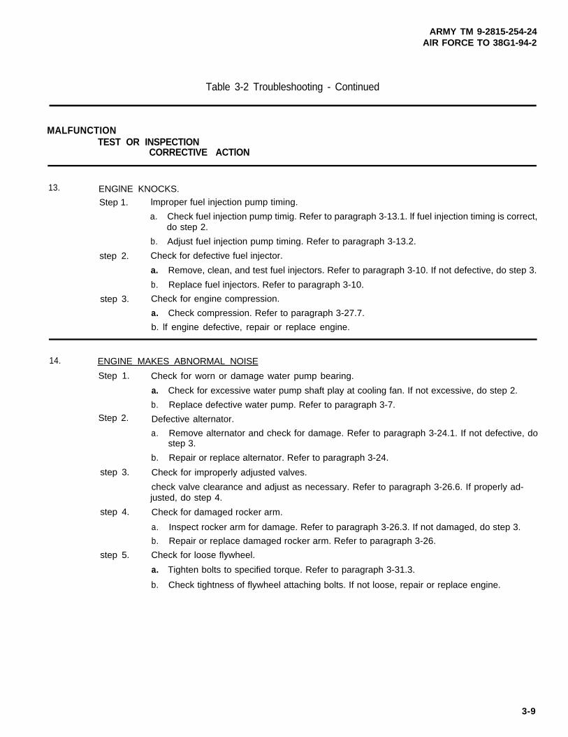
13. ENGlNE KNOCKS.
Step 1. lmproper fuel injection pump timing.
a. Check fuel injection pump timig. Refer to paragraph 3-13.1. lf fuel injection timing is correct,do step 2.
b. Adjust fuel injection pump timing. Refer to paragraph 3-13.2.
step 2. Check for defective fuel injector.
a. Remove, clean, and test fuel injectors. Refer to paragraph 3-10. If not defective, do step 3.
b. Replace fuel injectors. Refer to paragraph 3-10.
step 3. Check for engine compression.
a. Check compression. Refer to paragraph 3-27.7.
b. lf engine defective, repair or replace engine.
14.
step 3.
step 4.
step 5.
ENGINE MAKES ABNORMAL NOISE
Step 1. Check for worn or damage water pump bearing.
a. Check for excessive water pump shaft play at cooling fan. If not excessive, do step 2.
b. Replace defective water pump. Refer to paragraph 3-7.Step 2. Defective alternator.
a. Remove alternator and check for damage. Refer to paragraph 3-24.1. If not defective, dostep 3.
b. Repair or replace alternator. Refer to paragraph 3-24.
Check for improperly adjusted valves.
check valve clearance and adjust as necessary. Refer to paragraph 3-26.6. If properly ad-justed, do step 4.
Check for damaged rocker arm.
a. Inspect rocker arm for damage. Refer to paragraph 3-26.3. If not damaged, do step 3.
b. Repair or replace damaged rocker arm. Refer to paragraph 3-26.
Check for loose flywheel.
a. Tighten bolts to specified torque. Refer to paragraph 3-31.3.
b. Check tightness of flywheel attaching bolts. If not loose, repair or replace engine.
3-9

ARMY TM 9-2815-254-24AIR FORCE TO 30G1-94-2
Table 3-2. Troubleshooting - Continued
MALFUNCTIONTEST OR INSPECTION
CORRECTIVE ACTION
15. ENGINE MAKES A GAS LEAKING NOISE.
Step 1. Check for loose or damaged exhaust manifold.
a. Inspect for damaged and attaching hardware. IF not damage or loose, do step 2.
b. Tighten or replace exhaust manifold. Refer to paragraph 3-21.3.
Step 2. Check for loose fuel injection nozzle and/or glow plugs.
a. lnspect fuel injection nozzles and glow plus for looseness. lf not loose, do step 3.
b. lf loose, replace washers and tighten injection nozzles (paragraph 3-10) and/or glow plugs(paragraph 3-22.4).
Step 3. Check for damage cylinder head gasket.
a. lnspect area around cylinder head gasket for evidence of gas leakage.
b. Remove cylinder head and replace gasket. Refer to paragraph 3-27.
16. DETONATION OR PRE-IGNITIONStep 1.
Step 2.
Step 3.
Improper fuel injection pump timing.
a Adjust fuel injection pump timing. Refer to paragraph 3-13. lf timing is correct, proceed toStep 2.
Defect fuel injector nozzles.
a Test fuel injection nozzles. Refer to paragraph 3-10. lf fuel injection nozzles is not defective,proceed to Step 2.
b. Replace fuel injection nozzles. Refer to paragraph 3-10.
Carbon build-up in compression chamber.
a. Remove cylinder head and inspect for carbon build-up. Refer to paragraphs 3-27 and 3-32.
b. Remove carbon and/or replace components as necessary.
17. BATTERY CHARGE AMMETER SHOWS CHARGE WHEN BATTERIES ARE LOW.Step 1. Check for broken or loose fan belt.
a Inspect fan belt. Refer to end item maintenance manual. If belt not loose or broken, do step2.
b. Adjust or replace fan belt. Refer to end item maintenance manual.
Step 2. Test for defective battery charging alternator.
a Inspect and test battery charging alternator. Refer to paragraph 3-24.1. If alternator not defective, do step 3.
b. Repair or replace battery charging alternator. Refer to paragraph 3-24.
Step 3. Check for breaks or loose connections in charging circuit.
if breaks or loose connections are found, repair charging circuit. Refer to end item mainte-nance manual.
3-10 Change 1
ARMY TM 9-2815-254-24AlR FORCE TO 38G1-94-2
Table 3-2. Troubleshooting - Continued
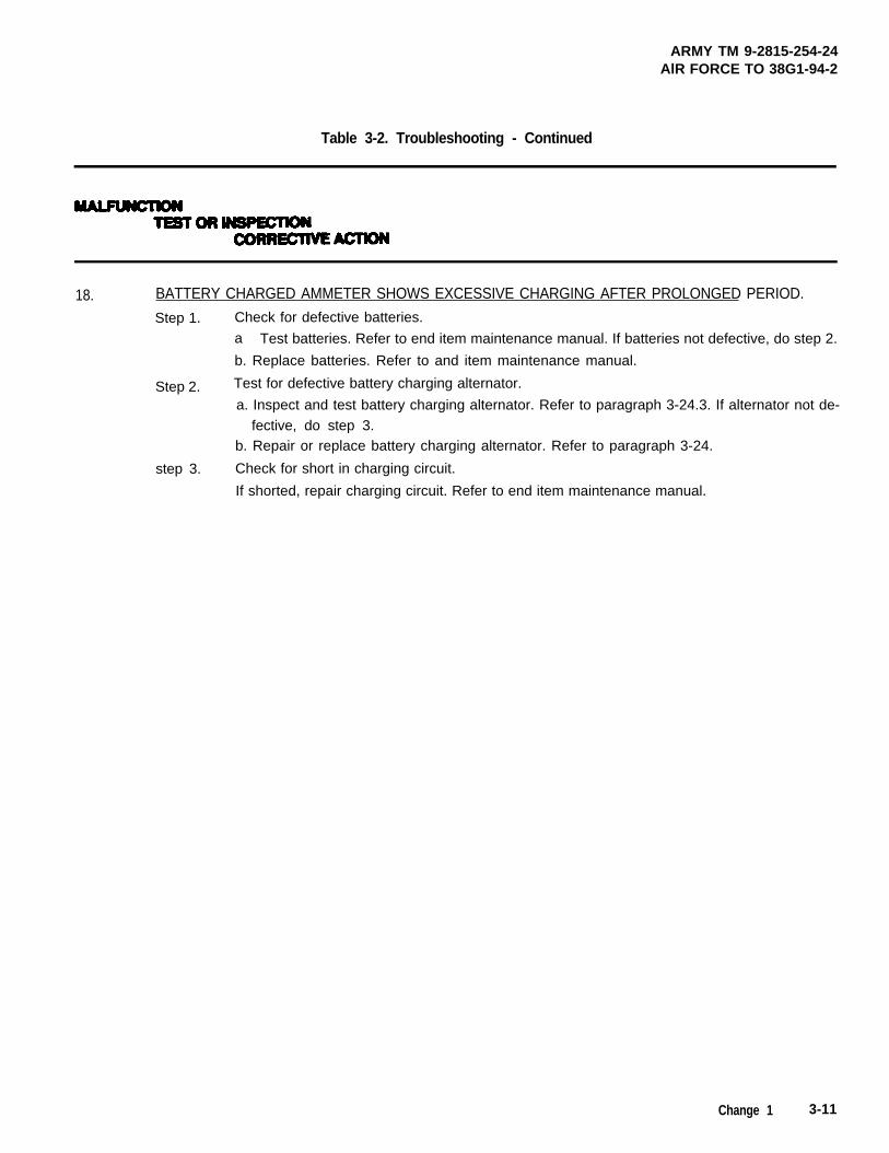
18. BATTERY CHARGED AMMETER SHOWS EXCESSIVE CHARGING AFTER PROLONGED PERIOD.
Step 1. Check for defective batteries.
a Test batteries. Refer to end item maintenance manual. If batteries not defective, do step 2.
b. Replace batteries. Refer to and item maintenance manual.
Step 2. Test for defective battery charging alternator.
fective, do step 3.a. Inspect and test battery charging alternator. Refer to paragraph 3-24.3. If alternator not de-
b. Repair or replace battery charging alternator. Refer to paragraph 3-24.
step 3. Check for short in charging circuit.
If shorted, repair charging circuit. Refer to end item maintenance manual.
Change 1 3-11

ARMY TM 9-2815-254-24AIRFORCE TO 38G1-94-2
SECTION III. GENERAL MAINTENANCE
3 - 3 . GENERAL
This section provides general maintenance not found in other sections of Chapter 3.
3-3.1 General Instructions.
Where applicable, prior to performing engine maintenance, ensure bat-teries are disconnecting. Failure to observe this warning could results insevere injury or death.
Refer to end item maintenance manual for removal of any componentsnecessary to gain access to engine.
It is strongly recommended that bolts or nuts securing cylinder heads, covers, and doors be tightened in prop-er sequence.
a
b.
C.
d.
e.
f.
g.
h.
i.
j.
k.
I.
m.
n.
When assembling an engine, it is always advisable nuts, bolts, and lockwashers that have beenremoved from high strsss locations, in particular nuts an&or bolts from connecting rods and cylinder headsshould be replaced.
When assembling an engine it is always advisable to apply a small quantity of new engine lubricating oil(MIL-L-2104) to all moving parts. After any maintenance work on engine has bean completed, lubricating oiland fuel levels must be checked and all safety guards installed before operating.
When a new fan drive belt has been installed, check belt tension after first 20 hours of operation.
Wear protective overalls, and keep items of loose clothing dear of all hot and moving pans. Use protectivebarrier cream when necessary.
Whenever possible, dean components and surrounding area before removing or disassembling. Take careto exclude all dirt and debris from fuel injection equipment while it is being serviced.
Some parts are cemented with gasket compound with others being dry. Before assembly, remove all tracesof old gasket and compound. Take extreme care to exclude dirt from all gasket surfaces and gasket com-pound from all tapped holes unless otherwise specified.
It is recommended that all oil seals are replaced once they have been removed from their original position.Seals must be installed square in housing and all lip seals must be installed with lip facing lubricant to be re-tained. A service tool should be used to install all oil seals and care must be taken to prevent damaging newseal when it passes over shafts.
Replace ail nuts, bolts, capscrews, and studs with damaged threads. Do not use a tap-or die to repair dam-aged threads which may impair the strength and closeness of the threads and is not recommended.
Do not allow grease or oil to enter a blind threaded hole as hydraulic action present when bolt or stud isscrewed in could split or stress housing.
To check or re-torque a bolt or nut, item is slackened a quarter of a turn and then tightened to specified value.
A steel ISO metric bolt, capscrew, or nut can be identified by the letter M either on head or one hexagon flat.The strength grade will also be marked on top or one flat.
On nuts with identification marks on one face the frictional area of that surface will be reduced, therefore nutshould be installed with unmarked face towards component.
Service took are designed to aid disassembly and assembly procedures and their use will prevent possibleunnecessary damage to components. It is recommended that service tools are always used, some operationscannot be safely carried out without aid of reIevant tooI.
3-4. DISASSEMBLY AND ASSEMBLY SEQUENCE FOR OVERHAUL.
The following paragraphs provide the sequence of disassembly and assembly for complete overhaul of the en-gine. Step-by-step procedures can be found in remaining sections of Chapter 3.
3 - 1 2 C h a n g e 1

ARMY TM 9-2815-254-24AIR FORCE TO 38G1-94-2
3-4.1. Disassembly.
a.
b.
c.
d.
e.
f.
g.
h.
i.
j.
k.
I.
If the engine has been operating and coolant is hot, allow engine to coolbefore you slowly loosen filler cap and relieve pressure from coolingsystem. Failure to observe this warning could result in severe personalinjury.
Use care when rotating engine on engine maintenance stand. If neces-sary, use a lifting device to avoid severe personal injury.
Drain all coolant and engine oil, refer to end item maintenance manual. Check engine oil for metal contami-nates.
Remove fan belt and alternator, refer to paragraph 3-24.1
Remove starter assembly, refer to paragraph 3-23.1.
Remove glow plugs, refer to paragraph 3-22.1.
Remove thermostat housing with thermostat, refer to paragraph 3-6.1.
Remove water pump, refer to paragraph 3-7.1.
Remove oil fitter and oil piping, refer to paragraphs 3-15.1 and 3-16.1.
Remove fuel filter, refer to paragraph 3-9.1.
Remove fuel injectors and piping, refer to paragraph 3-10.1.
Remove fuel injection pump, refer to paragraph 3-11.1.
Remove PCV assembly, refer to paragraph 3-20.1.
Remove intake and exhaust manifolds, refer to paragraph 3-21.1.
3-13

ARMY TM 9-2815-254-24AIR FORCE TO 38G1-94-2
m. Remove rocker arm cover and rocker arm assembly, refer to paragraph 3-26.1.
n. Remove pushrods, cylinder head assembly and cylinder head gasket, refer to paragraph 3-27.1. Check forbent push rods and discard cylinder head gasket.
o. Remove crank shaft pulley and front gear cover, refer to paragraph 3-25.1.
p. Remove oil pan, refer to paragraph 3-17.1.
q. Remove flywheel and flywheel housing, refer to paragraph 3-31.1
r. Remove crankcase, refer to paragraph 3-29.1.
s. Remove oil pump, refer to paragraph 3-18.1.
t. Remove idler gear assembly, refer to paragraph 3-30.1.
u. Remove pistons, connecting rods, and crankshaft, refer to paragraph 3-28.1.
v. Remove camshaft assembly, refer to paragraph 3-30.1.
w. Disassemble cylinder block assembly, refer to paragraph 3-32.1.
x. Cap/cover all openings to prevent entry of foreign material.
3-4.2. Assembly.
a. Remove all caps/covers installed during disassembly.
b. Assemble cylinder block assembly, refer to paragraph 3-32.3.
c. Install camshaft assembly, refer to paragraph 3-30.5.
d. Install crankshaft, pistons, and connecting rods, refer to paragraph 3-28.5.
e. Install idler gear assembly, refer to paragraph 3-30.5.
f. Install oil pump, refer to paragraph 3-18.3.
g. Install crankcase, refer to paragraph 3-29.3.
h. Install flywheel housing and flywheel, refer to paragraph 3-31.3.
3-14

ARMY TM 9-2815-254-24AIR FORCE TO 36G1-94-2
i. Install oil pan, refer to paragraph 3-17.3.
j. Install cylinder head assembly and Push rods, refer to paragraph 3-27-6.
k. install rocker arm assembly, refer to paragraph 3-26.5.
I. install intake and exhaust manifolds, refer to paragraph 3-21.3.
m. Install PCV assembly, refer to paragraph 3-20.3.
n. Install fuel injection pump, refer to paragraph 3-11.6.
o. install front gear cover and crankshaft pulley, refer to paragraph 3-25.3.
p. Time and adjust fuel injection pump, refer to paragraph 3-13.
q. Install fuel injectors and piping. refer to paragraph 3-10.7.
r. Install glow plugs, refer to paragraph 3-22.4.
s. Install fuel filter, refer to paragraph 3-9.4.
t. Install oil filter and piping, refer to paragraphs 3-15.4 and 3-16.2.
u. Install water pump, refer to paragraph 3-7.4.
v. Install thermostat housing with thermostat, refer to Paragraph 3-6.4.
w. Install starter assembly, refer to paragraph 3-23.6.
x. Install alternator and fan belt, refer to paragraph 3-24.5.
y. Adjust valves/rocker arm assembly, refer to paragraph 3-26.6.
z. Install rocker arm cover, refer to Paragraph 3-26.5.
aa. Fill engine with proper oil and coolant, refer to end item maintenance manual.
ab. Perform normal standard engine performance checks.
3-15

ARMY TM 9-2815-254-24.AIR FORCE TO 38G1-94-2
SECTION IV. COOLING SYSTEM MAINTENANCE
3-5 . GENERAL.
This section provides maintenance for cooling system components. Components of cooling system not men-tioned in this section can be found in the end item maintenance manual.
3-6. THEMOSTAT AND HOUSING.
If the engine has been operating and coolant is hot, allow engine to coolbefore you slowly loosen filler cap and relieve pressure from coolingsystem. Failure to observe this warning could result in severe personalinjury.
3-6.1. Removal
a. Drain coolant system if not already drained. Refer to end item maintenance manual.
b. If not already done, loosen hose clamp and disconnect outlet hose from outlet pipe (2, FIGURE 3-1).
FIGURE 3-1. Thermostat and Housing
3-16

ARMY TM 9-2815-254-24AIR FORCE TO 36G1-94-2
C.
d.
e.
f.
g.
Remove two screws (1) securing outlet pipe (2) to housing (8); remove outlet pipe (2) and gasket (3). Discardgasket (3).
Lift thermostat (4) from housing.
Loosen two hose clamps (10) and remove bypass hose (11) from housing (8) and water pump housing.
NOTE :
Note location of two shorter screws (6) for use during installation.
Remove four screws (6 and 7), housing (8), and gasket (9). Discard gasket (9).
If necessary, remove plugs (5) from housing (8).
3-6.2. Inspection.
N O T E
If thermostat is suspected of being defective, replace thermostat.
a. Inspect thermostat for excessive wear or damage.
b. Inspect housing for cracks, corrosion, or other damage.
3-6.3. Replacement.
a. Replace thermostat if worn or damaged.
b. Replace housing if badly corroded or damaged.
3-6.4. Installation.
a. If removed, install plugs (5, FIGURE 3-1) in housing (8).
b. Apply sealing compound (FORMAGASKET2) and position housing (8) with new gasket (9) on engine blockand secure with four screws (6 and 7). Install two shorter screws (6) in locations noted during removal. Tightenall four screws to 168 in-lbs (19 Nm)
c. Position thermostat (4) in housing (8).
3-17

ARMY TM 9-2815-264-24AIR FORCE TO 38G1-94-2
d. Apply sealing compound (FORMAGASKET2) and position outlet pipe (2) and new gasket (3) on housing (8)and secure with two screws (1). Tighten screws to 168 in-lbs (19 Nm).
e. Install bypass hose (11) on housing (8) and water pump housing and secure with two hose clamps (10).
f. Connect outlet hose to outlet pipe (2) and secure with hose clamp.
g. Service coolant system, refer to end item maintenance manual.
3-7. WATER PUMP.
3-7.1. Removal.
Do not drain coolant until coolant temperature is below operating tem-perature prior to removal. Severe personal injury can occur.
a. Drain coolant system if not already drained, refer to end item maintenance manual.
b. Loosen hose clamp and remove inlet hose from water pump outlet.
c. Remove fan drive belt, refer to end item maintenance manual.
d. Remove four screws (1, FIGURE 3-2) securing fan (2) spacer (3), and fan pulley (4) to water pump (7); re-move fan, spacer, and pulley.
N O T E
Note location of two longer screws (5) for use during installation.
e. Remove six screws (5 and 6) securing water pump (7); remove alternator bracket (8), water pump (7) andgasket (9). Discard gasket.
3-18

ARMY TM 9-2815-254-24AIR FORCE TO 36G1-94-2
3-7.2. Inspection.
a. Inspect pump rotation for abnormal noise, binding, and other abnormal conditions.
b. Inspect pump housing for cracks, corrosion, or any other damage.
3-7.3. Replacement. Replace pump assembly if inspection reveals any abnormal condition, such as bearing failure, ex-cessive end play, or abnormal rotation.
3-7.4. Installation.
Ensure longer bolts (5, FIGURE 3-2) are installed in the location notedduring removal. Failure to observe this caution will result in pump notbeing secured properly.
a. Apply sealant and position new gasket (9). water pump (7) and alternator bracket (8) on engine block andsecure with six screws (5 and 8). Tighten screws to 30 ft-lbs (40.6 Nm)
b. Position fan pulley (4) spacer (3) and fan (2) on water pump (7) hub and secure with four screws (1). Tightenscrew to 72 in-lbs (8.0 Nm).
c. Install fan drive belt, refer to end item maintenance manual.
3-19

ARMY TM 9-2815-254-24AIR FORCE TO 38G1-94-2
FIGURE 3-2. Water Pump
3-20
ARMY TM 9-2815-254-24AIR FORCE TO 38G1-94-2
SECTION V. FUEL SYSTEM MAINTENANCE
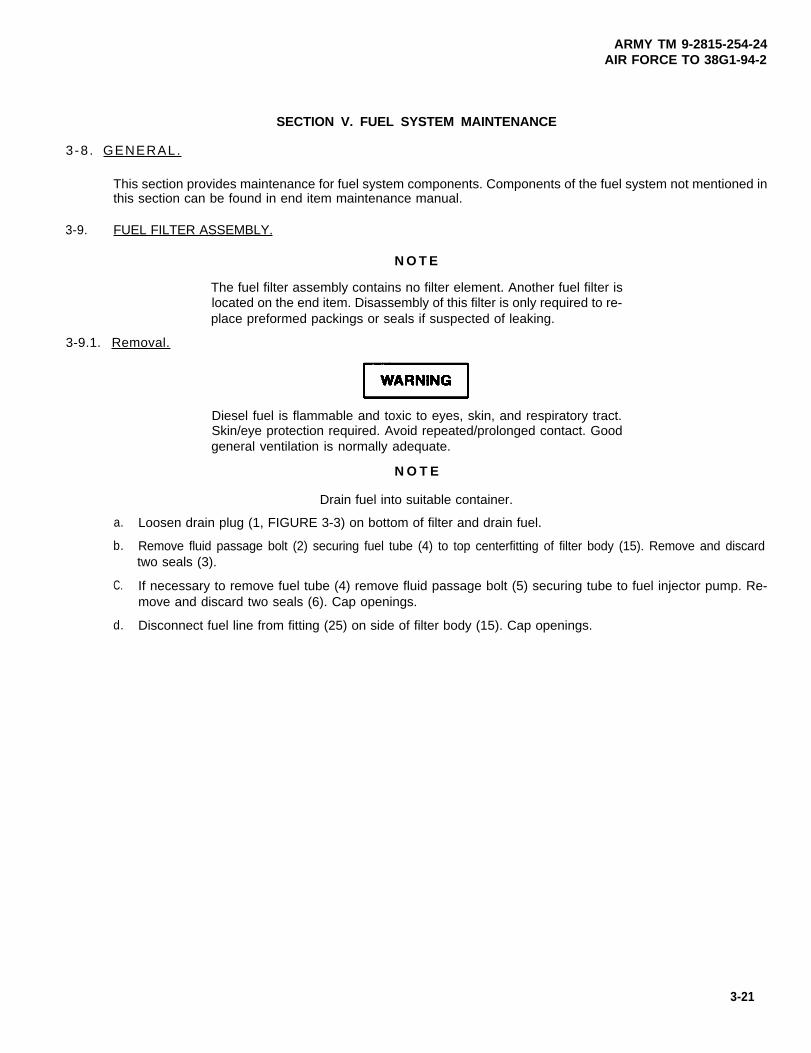
3-8 . GENERAL.
This section provides maintenance for fuel system components. Components of the fuel system not mentioned inthis section can be found in end item maintenance manual.
3-9. FUEL FILTER ASSEMBLY.
N O T E
The fuel filter assembly contains no filter element. Another fuel filter islocated on the end item. Disassembly of this filter is only required to re-place preformed packings or seals if suspected of leaking.
3-9.1. Removal.
a.
b.
C.
d.
Diesel fuel is flammable and toxic to eyes, skin, and respiratory tract.Skin/eye protection required. Avoid repeated/prolonged contact. Goodgeneral ventilation is normally adequate.
N O T E
Drain fuel into suitable container.
Loosen drain plug (1, FIGURE 3-3) on bottom of filter and drain fuel.
Remove fluid passage bolt (2) securing fuel tube (4) to top centerfitting of filter body (15). Remove and discardtwo seals (3).
If necessary to remove fuel tube (4) remove fluid passage bolt (5) securing tube to fuel injector pump. Re-move and discard two seals (6). Cap openings.
Disconnect fuel line from fitting (25) on side of filter body (15). Cap openings.
3-21

ARMY TM 9-2815-254-24AIR FORCE TO 38G1-94-2
e. Remove fluid passage bolt (7) securing fuel tube (9) to fluid passage bolt (7). Remove and discard two seals(8). Cap openings.
f. Disconnect fuel return line (10) to facilitate removal of fluid passage bolt (11). Cap openings.
g. Remove fluid passage bolt (11) securing fuel tube (13) to fitting on top of filter body (15). Removeand discardtwo seals (12).
h. Remove two bolts (14) securing filter body (15) to bracket (19); remove filter assembly.
i. If necessary, remove two bolts (16), washers (18) and lockwashers (17) securing bracket (19); removebracket. Discard lo&washers (17).
3-9.2. Disassembly.
a. Remove drain plug (1, FIGURE 3-3) and preformed packing (20) from thru-bolt (21). Discard preformed pack-ing (20).
b. Remove thru-bolt (21) and remove preformed packing (22), filter bowl (23), and preformed packing (24) frombody (15). Discard preformed packings (22 and 24).
c. If replacing entire filter assembly, remove and retain fitting (25).
3-9.3. Assembly.
a. Position new preformed packing (22, FIGURE 3-3) on thru-bolt (21). Position new preformed packing (24)and filter bowl (23) on body (15) and secure with thru-bolt (21). Tighten thru-bolt to 22 ft-lbs (29.8 Nm).
b. Install new preformed packing (20) and drain plug (1) into thru-bolt (21).
c. If removed, install fitting (25).
3-9.4. Installation.
a. If removed, position bracket (19, FIGURE 3-3) on engine block and secure with two bolts (16). new lockwash-ers (17), and washers (18).
3-22

ARMY TM 9-2815-254-24AIR FORCE TO 38G1-94-2
FIGURE 3-3. Fuel Filter Assembly
3-23

ARMY TM 9-2815-254-24AIR FORCE TO 38G1-94-2
b .
C.
d.
e.
f.
g.
h.
i.
j.
k.
I.
m.
Position filter assembly on mounting bracket and secure filter body (15) with two bolts (14). Do not tightenbolts until fuel tubes have been connected to filter and tightened.
Remove caps and install fuel return line (10).
Attach fuel tube (13) to fitting on top of filter body (15) with two new seals (12) and fluid passage bolt (11).Tighten fluid passage bolt (11) to 132 in-lbs (14.9 Nm).
Remove caps and attach fuel tube (9) to fluid passage bolt (11) with two new seals (8) and fluid passage bolt(7).
Remove caps and connect fuel line to fitting (25) on side of filter body (15).
If removed from fuel injection pump, remove caps and attach one end of fuel tube (4) to pump with two newseals (6) and fluid passage bolt (5).
Attach other end of fuel tube (4) to top center fitting of filter body (15) with two new seals (3) and fluid passagebolt (2).
Tighten fluid passage bolts (2, 5, 7, and 11) to 132 in-lbs (14.9 Nm).
Tighten filter mounting bolts (14).
Ensure filter drain plug (1) is tight.
Bleed engine fuel system, refer to paragraph 3-12.
Operate engine and check for leaks.
3-10. FUEL lNJECTORS AND PIPING.
3-10.1. Removal.
Fuel is flammable. Keep fuel away from heat and open flame. Failureto observe this warning could result in serious injury or death.
3-24

ARMY TM 9-2815-254-24AIR FORCE TO 38G1-94-2
Do not apply excessive force to injection fuel tubes. Failure to observethis caution could damage the equipment.
NOTE
Drain fuel into suitable container.
a. Loosen sleeve nut on fuel tubes (1, 2, 3, and 4, FIGURE 3-4) at fuel injection pump
b. Loosen sleeve nut on fuel tubes (1, 2, 3, and 4) at fuel injector.
c. Remove three clamp assemblies (5) and remove fuel tubes (1, 2, 3, and 4).
d. Cap all openings to prevent entry of foreign material.
e. At each fuel injector, remove fluid passage bolt (8) and two seals (7) securing fuel tube (10). At fuel filter, re-move fluid passage bolt (8) and two seals (9); remove fuel tube (10). Discard seals (7 and 9). Cap openings.
Handle each injector carefully to prevent damage to nozzle tip.
f. Unscrew each fuel injector (11) from block and remove washer (12) and washer (13) from each injector port.Discard washers (12 and 13). Cap or plug all openings.
3-10.2. Disassembly (Fuel Injector).
a. Loosen and remove cap nut (14, FIGURE 3-4) and gasket (15). Discard gasket (15).
b. Remove adjusting screw (16).
c. Remove washer (17), spring (18), and pushrod (19) from holder (25).
3-25

ARMY TM 9-2815-254-24AIR FORCE TO 38G1-94-2
FIGURE 3-4. Fuel lnjectors and Piping
3-26

ARMY TM 9-2815-254-24AIR FORCE TO 38G1-94-2
d. Remove retainer nut (20) and nozzle (21) from holder (25).
e. If necessary, remove screw (22), connector (23), and gasket (24) from holder (25). Discard gasket (24).
3-10.3. Inspection.
3-10.3.1 Fuel Injector.
a.
b.
c.
d.
e.
f.
g.
3-10.3.2.
a.
b.
The nozzle needle valve and nozzle body combinations must not be in-terchanged otherwise, injectors will not operate property.
Remove nozzle needle from nozzle body.
Clean fuel injector, refer to paragraph 3-10.4.
Insert nozzle needle in nozzle body and check for smooth movement of needle inside the body. If needle doesnot move smoothly after cleaning, replace nozzle.
Check nozzle body and nozzle needle for damage or deformation. If either is discovered, replace nozzle as-sembly.
Check both pushrod seating positions (nozzle needle and spring seat) for excessive wear and cracking. Ifeither is discovered, replace pushrod.
Inspect threaded components for thread damage and replace as necessary.
Inspect spring for cracks or missing coil.
Piping.
Inspect all fuel tubes (piping) for wear, kinks, or fitting damage. Replace as necessary.
Inspect fluid passage bolts for clogged passages. Clean or replace as necessary.
3-27

ARMY TM 9-2815-254-24AIR FORCE TO 38G1-94-2
3-10.4. Cleaning.
Cleaning solvent is flammable and toxic to eyes, skin, and respiratorytract. Skin/eye protection required. Avoid repeated/prolonged contact.Good general ventilation is nom-rally adequate.
a. Soak all parts except nozzle in a dry cleaning solvent (P-D-680) and wipe off all excess residue with a softcloth. Use wire brush to clean excessively dirty parts.
Clean nozzle holder mating surfaces with a piece of hard wood or a softcloth otherwise, damage will occur. Do not use a metal brush sincescars could cause leakage.
b. Remove nozzle needle valve from nozzle body. Holding the needle valve by stem, only clean shaft sectionand seat surface of needle valve with a piece of hardwood dipped in engine lubricating oil (ML-L-2104) ora clean soft cloth.
c. If a large amount of carbon residue remains and nozzle can not be cleaned well enough, dip nozzle in carboncleaner and repeat step b.
Compressed air used for cleaning can create airborne particles thatmay enter the eyes. Pressure will not exceed 30 psig (207 kPa). Eyeprotection required.
Never use sand paper, metal scraper, or other abrasive materials toclean nozzle body and needle valve, otherwise damage will occur.
3-28
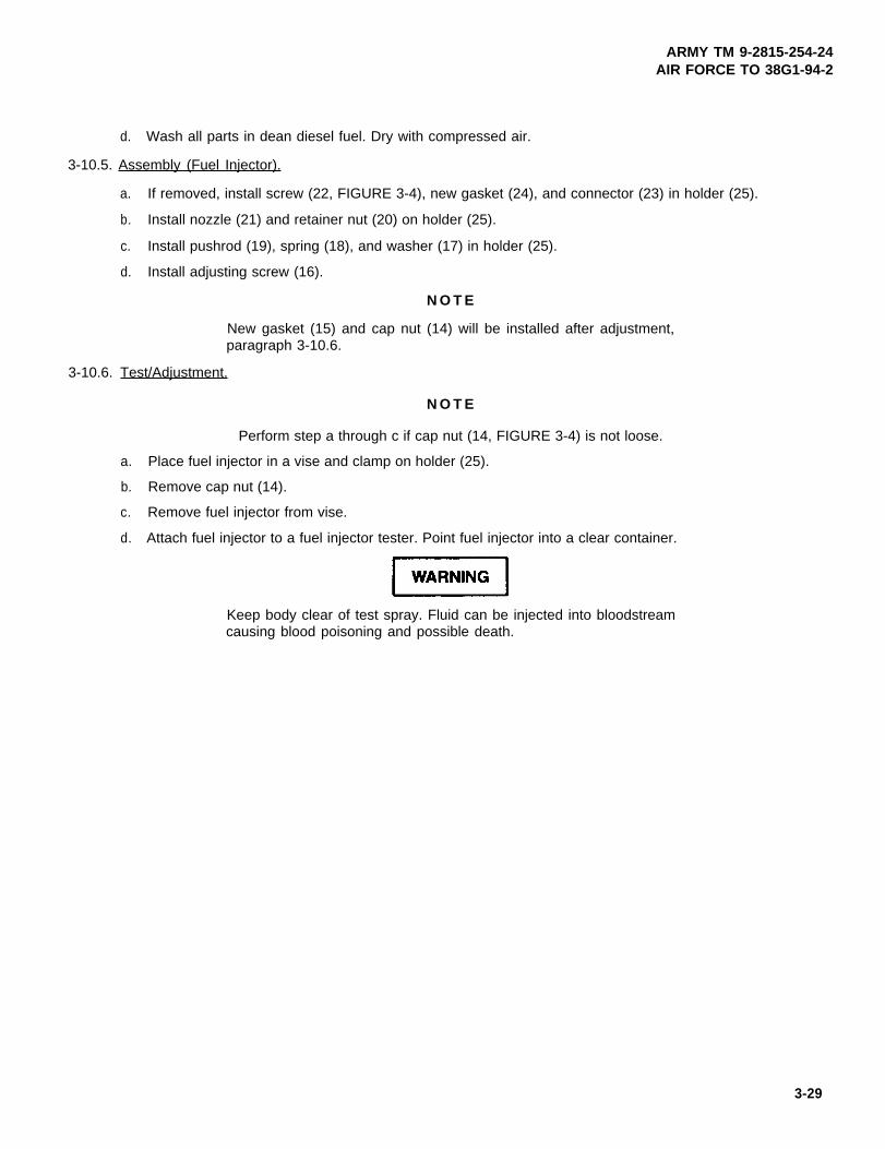
ARMY TM 9-2815-254-24AIR FORCE TO 38G1-94-2
d. Wash all parts in dean diesel fuel. Dry with compressed air.
3-10.5. Assembly (Fuel Injector).
a. If removed, install screw (22, FIGURE 3-4), new gasket (24), and connector (23) in holder (25).
b. Install nozzle (21) and retainer nut (20) on holder (25).
c. Install pushrod (19), spring (18), and washer (17) in holder (25).
d. Install adjusting screw (16).
N O T E
New gasket (15) and cap nut (14) will be installed after adjustment,paragraph 3-10.6.
3-10.6. Test/Adjustment.
N O T E
Perform step a through c if cap nut (14, FIGURE 3-4) is not loose.
a. Place fuel injector in a vise and clamp on holder (25).
b. Remove cap nut (14).
c. Remove fuel injector from vise.
d. Attach fuel injector to a fuel injector tester. Point fuel injector into a clear container.
Keep body clear of test spray. Fluid can be injected into bloodstreamcausing blood poisoning and possible death.
3-29

ARMY TM 9-2815-254-24AIR FORCE TO 36G1-94-2
e. Open valve on fuel injector tester and operate lever at one stoke per second.
f. Spray should start at 1706 psi (120 kg/cm2) and a well atomized spray pattern (refer to FIGURE 3-5) shouldbe visible.
FIGURE 3-5. Fuel Injector Spray Pattern
g. Turn adjusting screw (16, FIGURE 3-4) as necessary to obtain starting pressure and spray pattern in stepf.
h. Repeat step e and operate level to hold pressure at 290 psi (20.4 kg/cm2) below opening pressure.
i. No drops should fall from fuel injector within 10 seconds.
j. Remove fuel injector from tester and place in a vise.
k. Install capnut (14) and tighten to 25.5 ft-lbs (34.0 Nm).
l. Remove fuel injector from vise.
3-10.7. Installation.
N O T E
lf existing fuel injectors are being used, ensure they are installed in loca-tions as marked during removal.
3-30

ARMY TM 9-2815-254-24AIR FORCE TO 38G1-94-2
a.
b.
c.
d.
e.
f.
g.
h.
Remove caps/plugs and install new washers (12 and 13, FIGURE 3-4) in each injector port.
Install each fuel injector (11) and temporarity tighten them. Final tightening will be done after fuel tubes areconnected.
Remove caps and position fuel tubes (1, 2, 3, and 4) between fuel injection pump and their respective fuelinjector (11). Tighten sleeve nuts on each end evenly a little at a time, to reduce undue stress on the tubes,to 27 ft-lbs (36.6 Nm).
An improperly positioned clamp assembly (5) will result in objectionablefuel pulsing noise and possible fuel tube rupture.
Carefully position and tighten each of the three clamp assemblies (5).
Tighten fuel injector screw (22) to 54 ft-lbs (73.2 Nm).
Remove caps and position fuel tube (10) on each fuel injector (11) and at fuel filter. Secure to fuel fitter withfluid passage bolt (8) and two new seals (9). Secure to each fuel injector (11) with fluid passage bolt (6) andtwo new seals (7). Tighten each fluid passage bolt to 132 in-lbs (14.9 Nm)
Bleed engine fuel system, refer to paragraph 3-12.
Operate engine and check for leaks and proper operation.
3-11. FUEL INJECTION PUMP.
3-11.1. Removal.
a. Drain engine cooling and lubrication systems. Refer to end item maintenance manual.
Fuel is flammable. Keep fuel away from heat and open flame. Failureto observe this warning could result in serious personal injury or death.
3-31

ARMY TM 9-2815-254-24AIR FORCE TO 38G1-94-2
N O T E
Drain fuel into suitable container.
b. Disconnect fuel tubes (1, 2, 3, and 4, FIGURE 3-4) from delivery valve ports on fuel injection pump (3, FIGURE 3-7). Cap all openings.
c. Disconnect fuel tubes from top and bottom of fuel feed pump (10). Cap openings.
d. Remove fluid passage bolt (1, FIGURE 3-8) from top front of fuel injection pump securing fuel tube from fuelfitter. Remove and discard two seals (2). Cap openings.
e. Remove fluid passage bolt (3) from side of fuel injection pump securing oil feed tube. Remove and discardtwo preformed packings (4).
f. Remove/disconnect engine speed control system from fuel injection pump. Refer to end item maintenancemanual.
g. Rotate crankshaft pulley to align Top Dead Center (TDC) mark with pointer, refer to FIGURE 3-6.
FIGURE 3-6. lop Dead Center
h. Remove four screws (1, FIGURE 3-50) securing cover (2) to front gear cover (9); remove cover (2) and pre-formed packing (3). Discard preformed packing.
3-32

ARMY TM 9-2815-254-24AIR FORCE TO 33G1-94-2
i. Verify alignment of Z marks on timing gears.
N O T E
Note location of two longer bolts (2, FIGURE 3-7) for use during installa-tion.
j. Support weight of fuel injection pump (3) and remove four bolts (1) and two bolts (2) securing pump to enginefront plate. Remove pump (3) and packing (4). Discard packing (4).
3-11.2. Disassembly.
3-11.2.1.
a.
b.
c.
d.
e.
3-11.2.2.
a.
b.
c.
d.
e.
f.
Keep work area clean and orderty.
Record performance data for later reference. This data will facilitate detection and diagnosis of malfunctionsand defects, if any.
Lay out parts in order of disassembly. This will aid in reassembling pump.
Clean outer surface of pump. Remove all grease and dirt.
Drain lubricating oil from pump.
Procedure.
Mount fuel injection pump in soft-jawed vise.
Attach spanner (157916-5320) to timer assembly holder (7, FIGURE 3-7), remove nut (5), and lo&washer(6). Discard lo&washer (6).
Attach extractor (157926-6220) and spanner (157916-5320) to timer assembly (7) and remove timer assem-bly.
Remove four nuts (5, FIGURE 3-8), lockwashers (6), and washers (7) securing bracket (8) to pump; removebracket. Remove and discard preformed packing (10).
Remove pump from vise. Mount bracket (157944-7820) on universal vise (157944-8520).
Securely attach fuel injection pump to bracket using four bolts.
3-33

ARMY TM 9-2815-254-24AIR FORCE TO 38G1-94-2
FIGURE 3-7. Fuel Feed Pump and Timer Assembly
3-34

ARMY TM 9-2815-254-24AIR FORCE TO 38G1-94-2
FIGURE 3-8. Fuel Injection Pump Assembly
3-35

ARMY TM 9-2815-254-24AIR FORCE TO 38G1-94-2
g. Attach coupling (157842-4420) to camshaft and hold coupling using spanner (157916-5420). Tighten cou-pling nut.
FIGURE 3-9. Attaching Coupling (Typical)
h. Remove three nuts (8, FIGURE 3-7) and lockwashers (9) securing feed pump (10) to injection pump; removefeed pump (10) and preformed packing (11). Discard lockwashers (9) and preformed packing (11).
i. Remove two screws (11, FIGURE 3-8) securing cover (12) to side of pump; remove cover. Remove and dis-card two gaskets (13) and gasket (14).
j. Rotate camshaft (18) until tappet (23) is at TDC.
k. Insert tappet holder (fabricate four each in accordance with FIGURE D-1, Appendix D) into small hole on eachtappet (23) to disconnect tappet (23) from camshaft (18). Continue to rotate camshaft until one tappet holderis installed in each of four tappets, refer to FIGURE 3-10.
FIGURE 3-10. Inserting Tappet Holder (Typical)
3-36

ARMY TM 9-2815-254-24AIR FORCE TO 38G1-94-2
l. Refer to end item maintenance manual and remove governor mechanism from governor housing (17, FIG-URE 3-7).
m. Remove plug (12) and preformed packing (13) from top of governor housing (17).
n. Remove bolt (14) with retainer (15) and six screws (16) securing housing (17) to end of pump. By tappinghousing (17) lightly with a mallet, separate it from the pump. Remove and discard gasket (18).
o. Remove adapter (19) from pump housing (3).
p. Lay pump on its side and remove four plugs (15, FIGURE 3-8) from bottom of pump, refer to FIGURE 3-11.
FIGURE 3-11. Removing Screw Plug (Typical)
q. Secure pump in upright position.
r. Remove coupling from camshaft using spanner wrench and socket wrench, refer to FIGURE 3-12.
FIGURE 3-12. Removing Coupling (Typical)
3-37
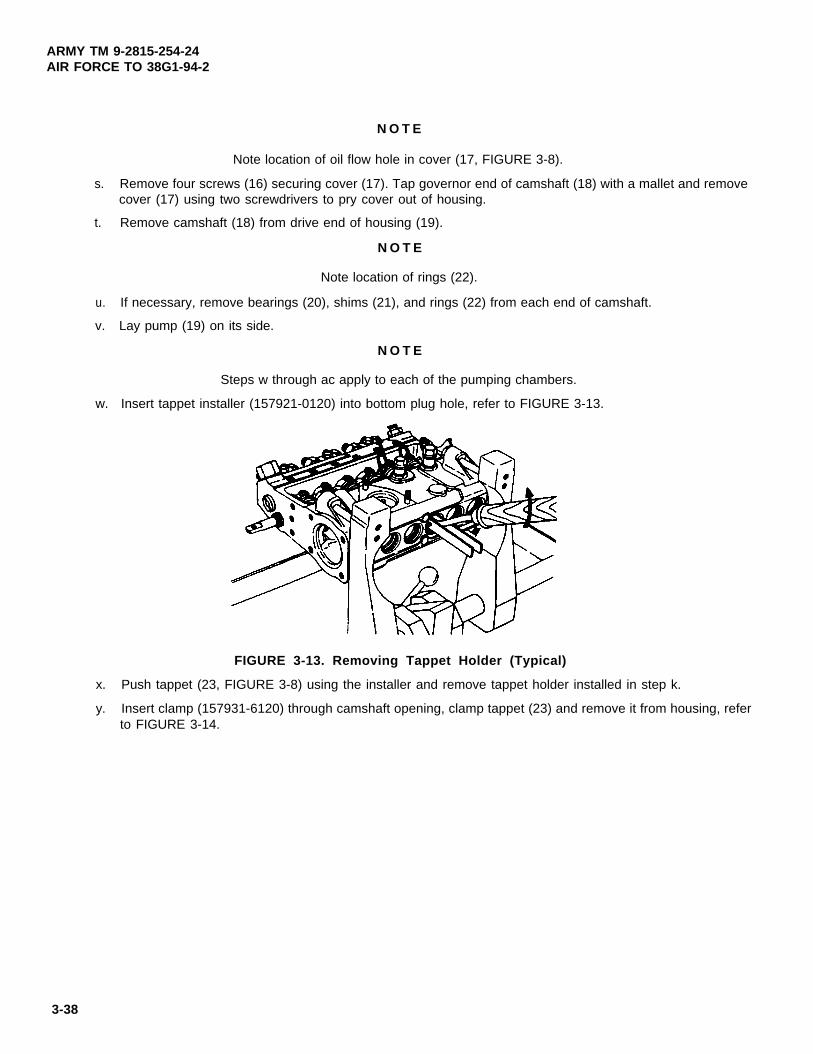
ARMY TM 9-2815-254-24AIR FORCE TO 38G1-94-2
N O T E
Note location of oil flow hole in cover (17, FIGURE 3-8).
s. Remove four screws (16) securing cover (17). Tap governor end of camshaft (18) with a mallet and removecover (17) using two screwdrivers to pry cover out of housing.
t. Remove camshaft (18) from drive end of housing (19).
N O T E
Note location of rings (22).
u. If necessary, remove bearings (20), shims (21), and rings (22) from each end of camshaft.
v. Lay pump (19) on its side.
N O T E
Steps w through ac apply to each of the pumping chambers.
w. Insert tappet installer (157921-0120) into bottom plug hole, refer to FIGURE 3-13.
FIGURE 3-13. Removing Tappet Holder (Typical)
x. Push tappet (23, FIGURE 3-8) using the installer and remove tappet holder installed in step k.
y. Insert clamp (157931-6120) through camshaft opening, clamp tappet (23) and remove it from housing, referto FIGURE 3-14.
3-38
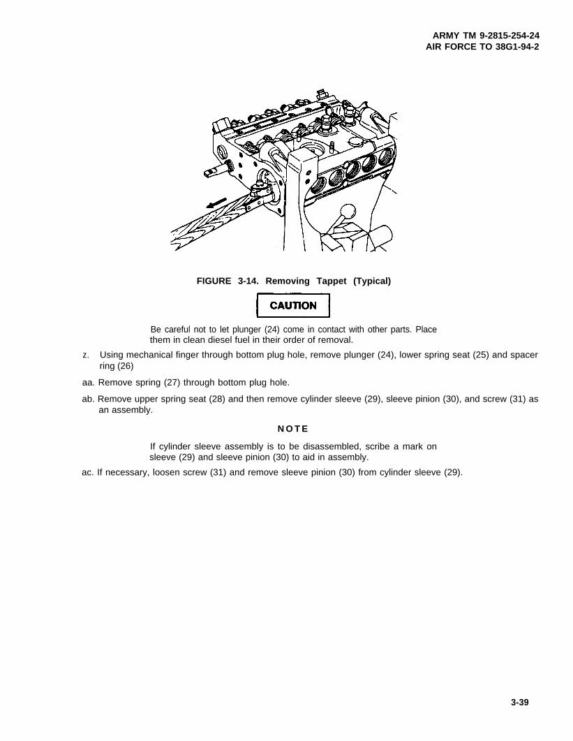
ARMY TM 9-2815-254-24AIR FORCE TO 38G1-94-2
FIGURE 3-14. Removing Tappet (Typical)
Be careful not to let plunger (24) come in contact with other parts. Placethem in clean diesel fuel in their order of removal.
z. Using mechanical finger through bottom plug hole, remove plunger (24), lower spring seat (25) and spacerring (26)
aa. Remove spring (27) through bottom plug hole.
ab. Remove upper spring seat (28) and then remove cylinder sleeve (29), sleeve pinion (30), and screw (31) asan assembly.
N O T E
If cylinder sleeve assembly is to be disassembled, scribe a mark onsleeve (29) and sleeve pinion (30) to aid in assembly.
ac. If necessary, loosen screw (31) and remove sleeve pinion (30) from cylinder sleeve (29).
3-39

ARMY TM 9-2815-254-24AIR FORCE TO 38G1-94-2
ad.
ae.
af.
ag.
ah.
ai.
aj.
Position pump in an upright position.
Remove two plate assemblies (32).
Loosen four delivery valve bodies (33).
Remove delivery valve body (33) and spring (34).
Screw extractor (1579299620) into delivery valve (35). Push down the pin and remove delivery valve (35)and gasket (36), refer to FIGURE 3-15.
FIGURE 3-15. Removing Delivery Valve
Be sure to keep each plunger (24, FIGURE 3-8) with its correspondingplunger barrel (37). If plungers and barrels are not matched, clearancesbetween them may not meet standard values.
Using a finger, push plunger barrel (37) out of housing, refer to FIGURE 3-16. Attach it to its correspondingplunger removed in step z and place it in clean diesel fuel.
Remove control rack guide screw (38, FIGURE 3-8).
ak. Withdraw control rack (39) from pump housing.
3-40
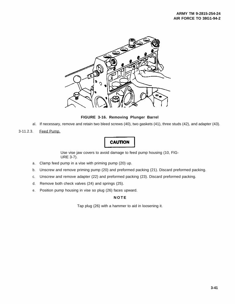
ARMY TM 9-2815-254-24AIR FORCE TO 38G1-94-2
FIGURE 3-16. Removing Plunger Barrel
al. If necessary, remove and retain two bleed screws (40), two gaskets (41), three studs (42), and adapter (43).
3-11.2.3. Feed Pump.
Use vise jaw covers to avoid damage to feed pump housing (10, FIG-URE 3-7).
a. Clamp feed pump in a vise with priming pump (20) up.
b. Unscrew and remove priming pump (20) and preformed packing (21). Discard preformed packing.
c. Unscrew and remove adapter (22) and preformed packing (23). Discard preformed packing.
d. Remove both check valves (24) and springs (25).
e. Position pump housing in vise so plug (26) faces upward.
N O T E
Tap plug (26) with a hammer to aid in loosening it.
3-41

ARMY TM 9-2815-254-24AIR FORCE TO 38G1-94-2
f.
g.
h.
i.
j.
3-11.2.4.
a.
b.
c.
d.
e.
f.
Remove plug (26).
Remove gasket (27) and spring (28). Discard gasket.
Remove piston (29).
Turn pump housing (10) over in vise. Remove and discard retaining ring (30).
Remove tappet (31) from housing and withdraw push rod (32).
Timer Assembly.
N O T E
Disassembly of the timer will only be necessary if timer does not meetthe specifications contained in paragraph 3-11.3.3. The only disassem-bly authorized is described below.
Mount base of inserter tool (157924-1620) in a vise.
If not already done, install guide bolt in base of inserter.
Position timer assembly (7, FIGURE 3-7) over guide bolt so that pins on inserter base enter holes in timerassembly (7) flyweight holder.
Remove six screws (33) securing gear (34) to flange (40); remove gear.
Flatten tab of lockplate (36).
Remove nut (35), lockplate (36), washer (37), shim (38), and washer (39) securing flange (40) to holder (7).Discard lockplate.
3-42

ARMY TM 9-2815-254-24AIR FORCE TO 38G1-94-2
3-11.3. Inspect.
Diesel fuel is flammable and toxic to eye-s, skin, and respiratory tract.Skin/eye protection required. Avoid repeated/prolonged contact. Goodgeneral ventilation is normally adequate.
a. Thoroughly wash all disassembled parts in clean diesel fuel.
b. Check each part carefully. If they are damaged or worn excessively, replace them.
c. Replace all gaskets and preformed packings. Do not reuse them.
3-11.3.1. Injection Pump.
a. Check that plunger helix (FIGURE 3-17) is not damaged, that color of plunger and plunger barrel (37, FIGURE3-8) have not changed and that Plungers move smoothly in barrels. If there are any problems, replace plungerand barrel as an assembly.
FIGURE 3-17. Plunger Helix
b. Ensure that plunger (24) slides smoothly into barrel (37) under its own weight when the assembly is inclinedapproximately 60 degrees. Change plunger position by rotating it and check plunger movement several timesas above. If plunger does not slide smoothly, replace plunger and barrel as an assembly, refer to FIGURE3-18.
3-43

ARMY TM 9-2815-254-24AIR FORCE TO 38G1-94-2
FIGURE 3-18. Checking Plunger and Barrel Movement
c. Inspect delivery valve (35, FIGURE 3-8) piston and seat for nicks, dents, and excessive wear. lf any signsof damage are evident, replace entire delivery valve assembly.
d. Holding delivery valve seat, close port with finger tip. Push valve into seat and check that it is returned (bythe air inside) when released, refer to FIGURE 3-19. If valve is not returned, then fit of piston in bore is tooloose (due to wear) to justify reuse of this delivery valve assembly. Replace the entire delivery valve assembly.
e. Check that control rack (39, FIGURE 3-8) is not bent. If bent, replace control rack.
FIGURE 3-19. Delivery Valve
3-44

ARMY TM 9-2815-254-24AIR FORCE TO 38G1-94-2
f. Check for excessive clearance between control rack (39) and bushing (45) that is press fitted into pump hous-ing (19). To check for end play, hold pinion and measure movement of control rack. If wear on working areaof control rack and bushing is excessive and play is more than 0.012 in. (0.3 mm), replace control rack.
g. Check for excessive wear of gear teeth on control rack (39) and sleeve pinion (30). If backlash is more than0.012 in. (0.3 mm), replace both control rack (39) and sleeve pinion (300).
h. Check that flange on plunger (24) is not damaged, refer to FIGURE 3-20. If damaged, replace plunger andbarrel as an assembly.
FIGURE 3-20. Checking Plunger and Barrel for Damage
i. Check cylinder sleeve (29, FIGURE 3-8) groove for damage or excessive wear. Replace if worn or damaged.
j. Check tappet (23) rollers, bushings, and pins for excessive wear, flaws, or peeling, refer to FIGURE 3-21.If damage is found, replace tappet.
FIGURE 3-21. Tappet
3-45

ARMY TM 9-2815-254-24AIR FORCE TO 38G1-94-2
k. Check top surface of lower spring seat (25, FIGURE 3-8) for damage, refer to FIGURE 3-22. If damaged, replace seat.
FIGURE 3-22. Lower Spring Seat
l. Check camshaft (18, FIGURE 3-8) for damaged or worn cam surfaces, refer to FlGURE 3-23. Check threaddamage and keyway groove on both ends. If damaged, replace camshaft.
FIGURE 3-23. Camshaft
m. Check bearings (20, FIGURE 3-8) for rollers deviating from inner race or peeled, damaged, or burnt surfaces,refer to FIGURE 3-24. If found defective, refer to FIGURE 3-25 and replace defective bearings by pressingbearings from shaft and race from cover (17, FIGURE 3-8) or governor housing (17, FIGURE 3-7).
3-46

ARMY TM 9-2815-254-24AIR FORCE TO 38G1-94-2
FIGURE 3-24. Camshaft Bearings
FIGURE 3-25. Bearing Removal
3-11.3.2. Feed Pump.
a. Inspect check valve (24, FIGURE 3-7) seats for wear or damage. If defective, replace check valve.
b. Check piston (29) for damage or cracks. If defective, replace piston.
c. Check tappet (31) rollers, bushing, and pin for excessive wear, flaws, or peeling. If defective, replace tappet,refer to FIGURE 3-26.
3-47

ARMY TM 9-2815-254-24AIR FORCE TO 38G1-94-2
FIGURE 3-26. Feed Pump Tappet
3-11.3.3. Tuner Assembly.
a. Visually inspect for broken springs. If springs are broken, replace timer assembly.
b. Inspect gear (34, FIGURE 3-7) for tooth wear. If defective, replace gear.
c. Using feeler gage, check clearance between washer (39) and shim (38). Clearance should be 0.0008 to 0.004in. (0.02 to 0.1 mm). If clearance is not within tolerance, change shim thickness.
3-11.4. Assembly.
3-11.4.1.
a.
b.
c.
d.
e.
f.
Mount base of inserter tool (157924-1620) in a vise.
Install holder (7, FIGURE 3-7) on base.
Install washer (39). shim (38), washer (37), new lockplate (36), and nut (35) on holder (7). Tighten nut 72 to130 ft-lbs (98 to 176 Nm).
Using a feeler gage, ensure that clearance between washer (39) and shim (38) is 0.0008 to 0.004 in. (0.02to 0.1 mm). If not change shim thickness.
Bend tab of lockplate (36) to lock nut (35).
Install gear (34) and screws (33). Torque screws 5.8 to 8.7 ft-lbs (7.8 to 11.7 Nm).
3-48

ARMY TM 9-2815-254-24AIR FORCE TO 38G1-94-2
3-11.4.2. Feed Pump.
a. Clamp pump housing in vise, with protected jaws, so tappet opening is facing upward.
b. Insert pushrod (32, FIGURE 3-7) and tappet (31) into housing.
c. Install new retaining ring (30).
d. Turn pump housing over in vise.
e. Install piston (29) and spring (28).
f. Install new gasket (27) and plug (26). Apply sealing compound (FORMAGASKET2) to threads and seatingface of plug (26). Tighten plug 63 ft-lbs (86.4 Nm).
FIGURE 3-27. Feed Pump Plug
g. Position pump housing so priming pump opening faces upward.
h. Install both check valves (24) and springs (25) into pump housing.
i. Install new preformed packing (23) and adapter (22) into housing. Tighten adapter 120 in-lbs (13.6 Nm).
j. Install new preformed packing (21) and priming pump (20) into pump housing. Using 15/16 in. crows footwrench, tighten priming pump 32 ft-lbs (43.4 Nm).
3-49

ARMY TM 9-2815-254-24AIR FORCE TO 38G1-94-2
3-11.4.3.
a.
b.
c.
d.
e.
f.
g.
h.
i.
lnjection Pump.
Mount pump housing (19, FIGURE 3-8) in bracket (157944-7820) mounted on universal vise (157944-8520)
Install four plunger barrels (37) so that locating pins in pump housing (19) mate with grooves in barrels (37).Ensure that barrels (37) cannot manually be rotated.
N O T E
If fuel injection pump is to be tested, leave springs (24), delivery valves(35), and gasket (36) out until prestroke test is complete.
Position delivery valves (35) with new gaskets (36) on plunger barrels (37).
Install four springs (34) and valve bodies (33) in pump housing. Tighten as follows:
(1) Tighten to 21.7 ft-lbs (29.4 Nm).
(2) Loosen to zero torque.
(3) Retighten to 21.7 ft-lbs (29.4 Nm).
(4) Loosen to zero torque.
(5) Finally tighten to 25.3 ft-lbs (34.3 Nm).
Install control rack (39) in pump housing.
Install measuring device (1057826280) on nipple (45). Use measuring device to position control rack (39)at center of travel. Install lock screw (38) in guide screw hole to lock control rack (39). Remove measuringdevice.
Lay pump housing over on its side.
If removed, position sleeve pinion (30) on cylinder sleeve (29) so that scribed marks (from disassembly) arealigned. Tighten screw (31) to 26.5 in-lbs (3.0 Nm).
Install cylinder sleeve (29) with split in sleeve pinion (30) facing upward.
Install guide screw (38) into back of pump housing. Ensure control rack (39) moves smoothly.
3-50

ARMY TM 9-2815-254-24AIR FORCE TO 38G1-94-2
k. Push control rack (39) fully toward drive side and then pull fully in opposite direction. Ensure that sleeve pinion(30) moves through same angle from control rack’scenter position when control rack is pushed or pulled, referto FIGURE 3-28.
FIGURE 3-28. Checking Sleeve Pinion Movement
l. Install upper spring seat (28) and spring (27) on plunger barrel (37) through bottom plug holes.
m. Dip plunger (24) in clean diesel fuel and hold it with mechanical fingers. Insert plunger with lower spring seat(25) into barrel (37) with helix facing upward and manufacturer’s mark facing downward, refer to FIGURE3-29.
FIGURE 3-29. Inserting Plunger
3-51
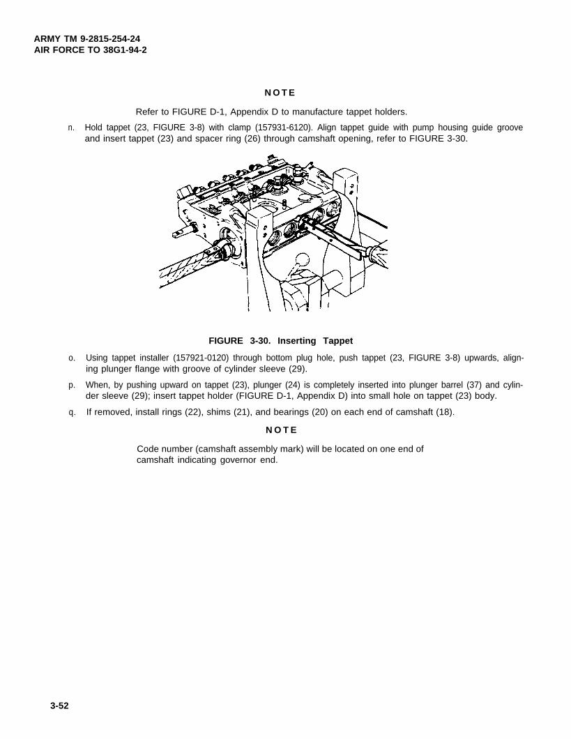
ARMY TM 9-2815-254-24AIR FORCE TO 38G1-94-2
N O T E
Refer to FIGURE D-1, Appendix D to manufacture tappet holders.
n. Hold tappet (23, FIGURE 3-8) with clamp (157931-6120). Align tappet guide with pump housing guide grooveand insert tappet (23) and spacer ring (26) through camshaft opening, refer to FIGURE 3-30.
FIGURE 3-30. Inserting Tappet
o. Using tappet installer (157921-0120) through bottom plug hole, push tappet (23, FIGURE 3-8) upwards, align-ing plunger flange with groove of cylinder sleeve (29).
p. When, by pushing upward on tappet (23), plunger (24) is completely inserted into plunger barrel (37) and cylin-der sleeve (29); insert tappet holder (FIGURE D-1, Appendix D) into small hole on tappet (23) body.
q. If removed, install rings (22), shims (21), and bearings (20) on each end of camshaft (18).
N O T E
Code number (camshaft assembly mark) will be located on one end ofcamshaft indicating governor end.
3-52

ARMY TM 9-2815-254-24AIR FORCE TO 38G1-94-2
r.
s.
t.
u.
v.
w.
x.
y.
z.
Install cover (17) so oil flow hole is facing as noted in disassembly on drive end and secure with four screws(16). Tighten screws 72 in-lbs (8.1 Nm).
Apply adhesive (242) and install four plugs (15) in bottom of pump. Tighten plugs 47 ft-lbs (63 7 Nm)
Place pump in upright position.
Install adapter (19, FIGURE 3-7) in pump housing (3).
Insert camshaft (18, FIGURE 3-8) into pump housing from governor end.
Position new gasket (18, FIGURE 3-7) and governor housing (17) on pump housing and secure with one bolt(14), retainer (15), and six screws (16). Tighten bolt (14) to 150 in-lbs (16.9 Nm) and screws (16) to 72 in-lbs(8.1 Nm).
If removed, install new preformed packing (13) and plug (12) in top of governor housing (17).
Checkcamshaft end play. Using a dial indicator measure end play. End play should be 0.001 to 0.002 in. (0.03to 0.05 mm). If end play is not within limits, remove camshaft and change thickness of shims (21, FIGURE3-8) and recheck end play.
Check control rack (39) sliding resistance by tipping pump back and forth. Check that rack moves freely.
aa. Using measuring device (1057826280) check the stroke of control rack (39). The stroke should be 0.83 in.(21 mm) from position where control rack is fully pushed toward governor to position where it is fully pulledtoward drive end. If stroke is not 0.83 in. (21 mm) it will be necessary to change engagement of sleeve pinions(30) with control rack to obtain proper stroke.
ab. Attach coupling (1578424420) to camshaft and hold coupling using spanner (157916-5420). Tighten nut oncoupling.
ac. Rotate camshaft (18) until tappet (23) is in TDC position.
ad. Remove tappet holders (FIGURE D-1, Appendix D) and continue to rotate camshaft until all the tappet holdersare removed. Confirm that camshaft rotates freely by manually rotating camshaft slowly.
3-53

ARMY TM 9-2815-254-24AIR FORCE TO 38G1-94-2
ae. Refer to end item maintenance manual and install governor mechanism.
af. Install two plate assemblies (32) to valve bodies (33). Tighten screw 36 in-lbs (4.1 Nm).
ag. Perform fuel injection pump test, refer to paragraph 3-11.5.
ah. Position new preformed packing (11, FIGURE 3-7) and feed pump (10) on pump housing and secure withthree new lockwashers (9) and nuts (8).
ai. Position cover (13, FIGURE 3-8) with new gasket (14) on side of pump housing and secure with two newgaskets (12) and screws (11).
aj. Position bracket (8) and new gasket (10) on drive end of housing and secure with four washers (7), new lock-washers (6), and nuts (5).
ak. Install timer assembly on camshaft and secure with new lockwasher (6, FIGURE 3-7) and nut (5). Attachspanner (157916-5320) to timer assembly to hold it while tightening nut (5) to 45 ft-lbs (61 Nm).
3-11.5. Testing.
a. If pump was not disassembled for cleaning and inspection, refer to paragraph 3-11.2.2 steps a thru d.
b. If not already installed, attach coupling (157842-4420) to camshaft and hold coupling using spanner (157916-5420). Tighten nut on coupling using socket wrench.
c. If not removed, remove feed pump, paragraph 3-11.2.2, step h.
d. If not removed, remove cover (13, FIGURE 3-8).
e. Remove pump from soft-jawed vice and mount pump on test stand.
N O T E
Refer to TABLE 3-1 for a listing of fuel pump test specifications.
f. Remove delivery valve bodies (33), springs (34), gaskets (36), and valves (35). Reinstall delivery valve bo-dies.
3-54

ARMY TM 9-2815-254-24AIR FORCE TO 38G1-94-2
g. Connect fuel pipes and injection pipes. Refer to TABLE 3-2 for correct sizes.
h. Plug feed pump opening with plastic plug. Fill camshaft chamber with engine lubricating oil (MIL-L-2104) (80cc). Fill governor chamber with engine oil, refer to PMCS chart (TABLE 3-1).
i. Remove control rack cap and attach measuring device (105782-6280).
j. Remove control rack guide screw (38) and lock control lever rack at 0.472 in. (12 mm) using locking screw.
k. Attach measuring device (105782-4020) to pump housing No. 2 cylinder. Measuring needle must rest on tap-pet guide pin.
l. Place No. 2 cylinder cam in bottom dead center (BDC) position. Set dial gage indicator to zero (0).
NOTE
Manually rotate camshaft by hand and ensure that indication of dialgage indicator varies with change in cam lift.
FIGURE 3-31. Measuring Device Installed (Typical)
m. Supply test oil to injection pump at as low a pressure as possible (2.8 psi (19.6 kPa)
3-55

ARMY TM 9-2815-254-24AlR FORCE TO 36G1-94-2
TABLE 3-1. Fuel Pump Test Specifications
3-56

ARMY TM 9-2815-254-24AIR FORCE TO 38G1-94-2
p.
q.
r.
s.
t.
u.
v.
w.
x.
y.
z. Confirm that camshaft rotates smoothly by manually rotating camshaft slowly
If pre-stroke is not 0.087 to 0.091 in. (2.20 to 2.30 mm), adjust as follows:
(1) Rotate camshaft until No. 2 cam reaches TDC position.
(2) Insert plunger spring holder (157931-4100) between lower spring seat (25. FIGURE 3-8) and tappet (23).
(3) Remove spacer ring (26) and install spacer ring that will provide desired pre-stroke. Spacer rings areavailable in 0.002 in. (0.05 mm) steps.
(4) Remeasure No. 2 cylinder’s pre-stroke.
Set pump test stand flywheel pointer to an arbitrary angle graduation, with No. 2 cam placed in beginning ofinjection position.
Ensure test oil stops flowing from measuring device pipe in this position.
Do not move flywheel pointer after it has been placed in this position.
Remove measuring device from No. 2 cylinder.
Supply test oil at high pressure to injection pump.
Open nozzle holders overflow valves so test oil flows.
Measure beginning-of-injection positions in order of injection.
Rotate camshaft until test oil stops flowing from overflow pipe.
Read pointer indication on flywheel.
If angle interval is not between 89.5 and 90.5 degrees between each cylinder in firing order (1-3-4-2), adjustusing spacer ring (26). If oil stops flowing prematurely, decrease thickness of shim, if oil stops flowing too late,increase thickness of shim.
3-57

ARMY TM 9-2815-254-24AIR FORCE TO 38G1-94-2
aa. Install valves (35), gaskets (36), springs (34), and bodies (33), refer to paragraph 3-11.4.3.
N O T E
Ensure fuel injection pump is bled of all air before doing following steps.
ab. Set test stand for an inlet pressure of 23 psi (1.6 Kg/cm2).
ac. Ensure control rack is at 0.472 in. (12 mm) position, pump speed at 1450 rpm and plunger strokes for 1000.
ad. Operate test stand and measure fuel injection quantity for each cylinder. Each cylinder should measure 42to 44 cc with + 1.08 cc between cylinders.
ae. If fuel injection quantity is not as specified, adjust as follows:
N O T E
Scribe a mark to identify starting point.
(1) Loosen sleeve pinion screw (31).
(2) Rotate cylinder sleeve (29) clockwise or counterclockwise using an appropriate tool. Rotating cylindersleeve towards governor increases fuel injection quantity.
af. Repeat steps ab thru ae for the following settings.
(1) Pump speed 350 rpm.
(2) Plunger strokes 1000.
(3) Control rack at 0.299 in. (7.6 mm) position.
(4) Each cylinder should measure 6.9 to 9.1 cc with + 1.12 cc between cylinders.
ag. Remove rack lock screw from pump housing and reinstall control rack guide screw (38).
3-58

ARMY TM 9-2815-254-24AIR FORCE TO 38G1-94-2
ah. Perform feed pump suction test as follows:
(1) Install feed pump, paragraph 3-11.4.2.
(2) Attach a 6.5 ft (2 m) length of 0.315 in. (8 mm) ID pipe to suction port of feed pump and insert other endinto fuel container. Refer to FIGURE 3-32.
(3) Attach pipe to discharge port of feed pump and insert other end into empty container.
N O T E
Ensure a suction head of approximately 3.3 ft (1 m).
FIGURE 3-32. Feed Pump Test
(4) Operate injection pump at 100 rpm.
(5) Fuel oil must be discharged in less than 60 seconds.
ai. Perform feed pump priming pump test as follows:
(1) Pump should be piped as in step ah, refer to FIGURE 3-33.
(2) Fully loosen priming pump’s screw cap.
(3) Operate priming pump at 60 to 100 strokes per minute.
(4) Fuel oil must be discharged in less than 25 strokes.
3-59

ARMY TM 9-2815-254-24AIR FORCE TO 38G1-94-2
FIGURE 3-33. Priming Pump Test
aj. Perform feed pump capacity test as follows:
N O T E
Feed pump can be tested for capacity while installed on engine. Discon-nect discharge hose and insert in measuring container. Crank enginefor 15 seconds. Supply rate should be at least 60 cc. Replace feedpump if it fails to meet supply rate.
(1) Pump should be piped as in step ah, except place end of discharge pipe in a measuring cylinder, referto FIGURE 3-34.
(2) Operate injection pump at speeds specified in TABLE 3-2 and check for corresponding supply rate.
3-60

ARMY TM 9-2815-254-24AIR FORCE TO 38G1-94-2
FIGURE 3-34. Capacity lest
TABLE 3-2. Capacity Test
ak. Perform feed pump feed pressure measurement as follows:
(1) Pump suction as piped in step ah, refer to FIGURE 3-35.
(2) Pump discharge connected to test stand pressure gage
(3) Operate injection pump at 600 rpm.
(4) Ensure that feed pump maintains a feed pressure of 25.6 to 35.5 psi (176.5 to 244.8 kPa)
al. Perform feed pump air tightness test as follows:
(1) Remove feed pump from pump housing. Refer to paragraph 3-11.2.2, step h.
3-61

ARMY TM 9-2815-254-24AIR FORCE TO 38G1-94-2
FIGURE 3-35. Feed Pump Pressure Test
(2) Install plug in discharge port.
(3) Connect an air supply to suction port and apply a pressure of 28.5 psi (196.5 kPa).
(4) Immerse feed pump in a container of diesel fuel and check for air leakage. There must be no air leakage.
(5) Install feed pump on pump housing. Refer to paragraph 3-11.4.2.
FIGURE 3-36. Air Tightness Test
3-62
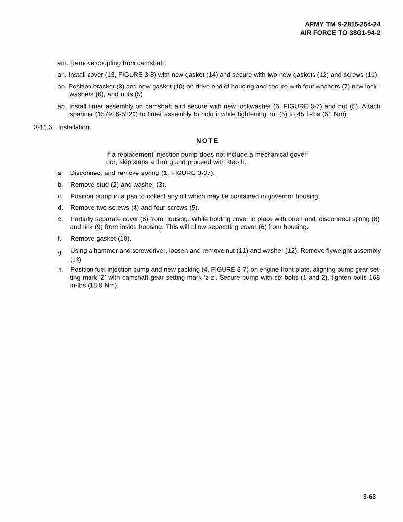
ARMY TM 9-2815-254-24AIR FORCE TO 38G1-94-2
am. Remove coupling from camshaft.
an. Install cover (13, FIGURE 3-8) with new gasket (14) and secure with two new gaskets (12) and screws (11).
ao. Position bracket (8) and new gasket (10) on drive end of housing and secure with four washers (7) new lock-washers (6), and nuts (5)
ap. Install timer assembly on camshaft and secure with new lockwasher (6, FIGURE 3-7) and nut (5). Attachspanner (157916-5320) to timer assembly to hold it while tightening nut (5) to 45 ft-lbs (61 Nm)
3-11.6. Installation.
a.
b.
c.
d.
e.
f.
g.
h.
N O T E
If a replacement injection pump does not include a mechanical gover-nor, skip steps a thru g and proceed with step h.
Disconnect and remove spring (1, FIGURE 3-37).
Remove stud (2) and washer (3).
Position pump in a pan to collect any oil which may be contained in governor housing.
Remove two screws (4) and four screws (5).
Partially separate cover (6) from housing. While holding cover in place with one hand, disconnect spring (8)and link (9) from inside housing. This will allow separating cover (6) from housing.
Remove gasket (10).
Using a hammer and screwdriver, loosen and remove nut (11) and washer (12). Remove flyweight assembly(13).
Position fuel injection pump and new packing (4, FIGURE 3-7) on engine front plate, aligning pump gear set-ting mark ‘Z’ with camshaft gear setting mark ‘z-z’. Secure pump with six bolts (1 and 2), tighten bolts 168in-lbs (18.9 Nm).
3-63

ARMY TM 9-2815-254-24AIR FORCE TO 38G1-94-2
i. Install engine front cover access plate, refer to paragraph 3-25.3 step h.
j. Connect/assemble engine speed control system to fuel injection pump. Refer to end item maintenance manu-al.
k. Position oil feed tube to side of pump and secure with two new preformed packings (4, FlGURE 3-8) and fluidpassage bolt (3). Tighten bolt to 132 in-lbs (14.9 Nm).
l. Remove caps and position fuel tube from fuel filter on top front of fuel injection pump and secure with twonew seals (2) and fluid passage bolt (1). Tighten bolt to 132 in-lbs (14.9 Nm)
m. Remove caps and connect fuel tubes to top and bottom of fuel feed pump (10, FIGURE 3-7).
n. Remove caps and connect fuel tubes to delivery valve ports on fuel injection pump, refer to paragraph 3-10.7,step c.
FIGURE 3-37. Removal of Mechanical Governor
3 - 6 4

ARMY TM 9-2815-254-24AIR FORCE TO 38G1-94-2
o. Service engine cooling and lubrication systems, refer to end item maintenance manual.
p. Bleed air from fuel system, refer to paragraph 3-12.
q. Operate engine and check for leaks.
3-12. BLEEDING AND PRIMING FUEL SYSTEM.
3-12.1.
a. Loosen priming pump cap on fuel injection pump.
b. Prime fuel injection pump several times.
c. Loosen bleeder screw (40, FIGURE 3-8) on fuel injection pump.
Fuel is flammable. Keep fuel away from heat and open flame. Failureto observe this warning could result in severe personal injury or death.
N O T E
Drain fuel into suitable container.
d. Operate priming pump (20, Figure 3-7) until no more bubbles are visible in fuel being discharged from bleederscrews.
e. Retighten bleeder screws and priming pump cap securely after bleeding.
3-13. FUEL lNJECTlON PUMP TIMING.
3-13.1. Checking Procedure.
a. Check that notched line on injection pump fixing flange is aligned with injection pump mounting flange’snotched line.
b. Align crankshaft pulley TDC mark with pointer.
c. Rotate crankshaft pulley counterclockwise approximately 30 degrees.
d. Disconnect injection pipe from delivery valve No. 1.
3-65

ARMY TM 9-2815-254-24AIR FORCE TO 38G1-94-2
e. Remove No. 1 plate assembly (32, FIGURE 3-8), valve body (33), spring (34); gasket (36). and valve (35).
f. Install valve body (33) and tighten to 31 ft-lbs (42.0 Nm).
Take care to avoid entry of dirt or foreign particles in fuel injection pumpwhile delivery valve is removed. Otherwise, damage to pump could oc-cur.
g. Hold fuel control lever to full fuel position.
h. Slowly turn crankshaft pulley clockwise and at same time operate priming pump to cause fuel to flow fromNo. 1 delivery valve.
i. When fuel stops flowing from No. 1 delivery valve, stop pumping and stop rotating crankshaft. This is correctfuel injection timing.
j. Observe and ensure that crankshaft pulley middle timing mark (18 degrees) is aligned with pulley.
k. Blow remaining fuel from No. 1 delivery valve holder and check that no fuel flows as pumping is continued.
I. Remove delivery valve body (33). Install valve (35), gasket (38), spring (34), valve body (33), and plate as-sembly (32), refer to paragraph 3-11.4.3, steps c, d, and af.
m. Reconnect injection pipe to No. 1 delivery valve, refer to paragraph 3-10.7, step c.
Operating engine with priming pump cap in unscrewed position will re-sult in priming pump failure.
n. Tighten priming pump cap.
3-66

ARMY TM 9-2815-254-24AIR FORCE TO 38G1-94-2
3-13.2. Adjustment Procedure.
a. Align timing pointer at timing gear case and middle (18 degrees) injection timing notch line on crankshaftpulley.
b. Disconnect injection pipe from delivery valve No. 1. Cap openings.
c. Remove No. 1 plate assembly (32, FIGURE 3-8), valve body (33), spring (34), gasket (36), and valve (35).refer to paragraph 3-11.2.2.
d. Install valve body (33) and tighten to 31 ft-lbs (42.0 Nm).
Take care to avoid entry of dirt or foreign particles in fuel injection pumpwhile delivery valve is removed. Otherwise, damage to pump could oc-cur.
e. Hold fuel control lever to full fuel position.
N O T E
Injection timing adjustment is done by pivoting injection pump at driveshaft. Pivot pump body toward outside of engine to advance timing. Piv-ot pump body toward inside of engine to retard timing.
f. Disconnect other injection pipes at delivery valves to allow pump to pivot easily. Cap openings.
g. Loosen four nuts (5) mounting pump and pivot pump body.
N O T E
Movement of 0.04 in. (1.0 mm) corresponds to approximately 2 degreesin crank angle.
h. Operate priming pump to allow fuel to flow from No. 1 delivery valve.
3-67

ARMY TM 9-2815-254-24AIR FORCE TO 38G1-94-2
i. While continuing to pump as described in step h, pivot pump body toward inside or outside of engine untilfuel stops flowing from No. 1 delivery valve. This is the correct fuel injection timing.
j. Blow remaining fuel from No. 1 delivery valve holder and check that no fuel flows as pumping is continued.
N O T E
Remove fuel priming pump and PCV hoses as necessary to torquenuts.
k. Tighten four nuts (5) securing pump to 168 in-lbs (19.0 Nm).
l. Remove delivery valve body (33). Install valve (35), gasket (36), spring (34), and valve body (33), refer toparagraph 3-11.4.2.
m. Remove caps and reconnect injection pipes to delivery valves, refer to paragraph 3-10.7.
Operating engine with priming pump cap in unscrewed position will re-sult in priming pump failure.
n. Tighten priming pump cap.
3-68

ARMY TM 9-2815-254-24AIR FORCE TO 38G1-94-2
SECTION VI. LUBRICATION SYSTEM
3-14. OIL FILTER.
3-14.1. Cartridge Replacement.
a. Drain lubrication system, refer to end item maintenance manual.
b. Loosen cartridge (1, FIGURE 3-38) by turning counterclockwise with a filter wrench.
c. Discard used cartridge.
d. Wipe filter head (2) with a clean rag.
e. Apply light coat of oil to new cartridge (1) gasket.
f. Place cartridge on filter head (2) and turn clockwise until cartridge is hand-tight on head.
g. Using filter wrench, turn cartridge an additional 1 to 1-1/4 turns.
h. Service lubrication system, refer to end item maintenance manual.
i. Operate engine and check for leakage.
3-14.2. Removal.
a. Drain lubrication system, refer to end item maintenance manual.
b. Remove four screws (3, FIGURE 3-38) securing filter head (2) to engine; remove filter head ando-ring (4).
NOTE
Cartridge (1) does not have to to be removed to remove head.
c. Cover opening to prevent entry of dirt.
3-14.3. Installation.
a. Wipe engine and filter head (2, FIGURE 3-38) mating areas with a clean rag.
b. Install o-ring (4). Position head (2) on engine and secure with four screws (3). Tighten screws to168 in-lbs (19.0 Nm).
Change 2 3-69

ARMY TM 9-2815-254-24AIR FORCE TO 38G1-94-2
FIGURE 3-38. Oil Filter
c. Install cartridge (1) if necessary, refer to paragraph 3-14.1.
d. Service lubrication system, refer to end item maintenance manual.
e. Operate engine and check for leakage.
3-15. OIL PRESSURE RELIEF VALVE.
3-15.1. Removal.
a. Drain lubrication system, refer to end item maintenance manual.
b. Remove oil pressure relief valve (5, FIGURE 3-38) and o-ring (6).
c. If necessary, remove plug (7) and seal (8). Discard seal (8).
3-15.2. lnspection.
a. Inspect oil pressure relief valve (5, FIGURE 3-38) for damaged threads or other damage.
b. Inspect plug (7) for damage.
3-70 Change 2

ARMY TM 9-2815-254-24AIR FORCE TO 38G1-94-2
3-15.3. Testing.
a. Tag, disconnect, and remove oil pressure sending unit, if supplied.
b. Install oil pressure gage (0-150 psi).
c. Start engine and check oil pressure relief valve opening. Valve should open between 82.5 to 88.2psi (568 to 608 kPa).
d. Replace oil pressure relief valve if valve fails to open as specified above.
e. Remove oil pressure gage and install oil pressure sending unit (if supplied). Connect electricalconnection and remove tag.
3-15.4. Installation.
a. If removed, install plug (7) with new seal (8). Torque plug between 18.1 to 25.3 ft-lbs (24.5 to34.3 Nm).
b. Install oil pressure relief valve (5) and o-ring (6). Torque relief valve between 18.1 to 25.3 ft-lbs(24.5 to 34.3 Nm)
c. Service lubrication system, refer to end item maintenance manual.
d. Operate engine and check for leakage.
3-16. OIL PIPING.
3-16.1. Removal.
a. Drain lubrication system, refer to end item maintenance manual.
b. Remove fluid passage bolt (1, FIGURE 3-39) securing valve rocker oil feed pipe (3). Remove pipeand two gaskets (2). Discard gaskets (2).
c. Remove two fluid passage bolts (4) and bolt (6) securing fuel injection pump oil pipe (7). Removepipe and four gaskets (5). Discard gaskets (5).
Change 2 3-71

ARMY TM 9-2815-254-24AIR FORCE TO 38G1-94-2
FIGURE 3-39. Oil Piping
3-72

ARMY TM 9-2815-254-24AIR FORCE TO 35G1-94-2
3-16.2. Installation.
a. Position fuel injection pump oil pipe (7, FIGURE 3-39) and secure with four new gaskets (5), twofluid passage bolts (4), and bolt (6). Tighten bolts (4) to 84 in-lbs (9.5 Nm).
b. Position valve rocker oil fuel pipe (3) and secure with two new gaskets (2) and fluid passage bolt(1). Tighten bolt to 84 in-lbs (9.5 Nm).
c. Service lubrication system, refer to end item maintenance manual.
d. Operate engine and check for leaks.
3-17. OIL PAN.
3-17.1. Removal,
a. Drain lubrication system, refer to end item maintenance manual.
b. Disconnect PVC hose.
c. Remove dipstick (I, FIGURE 340) and gasket (2). Discard gasket.
d. Remove screw (3) and washer (4) securing dipstick tube.
FIGURE 3-40. Oil Pan Assembly
Change 2 3-73

ARMY TM 9-2815-254-24AIR FORCE TO 38G1-94-2
e. Support oil pan and remove thirty screws (5) securing oil pan. Remove oil pan (6) and gasket (6).Discard gasket.
f. If not removed, remove drain plug (8) and gasket (9).
3-17.2. Inspection.
a. Inspect dipstick (1, FIGURE 3-40) for legibility. Replace if damaged.
b. Inspect gasket (2) for deterioration and replace as necessary.
c. Inspect oil pan (6 for cracks, dents, or other damage. Replace if damaged.
3-17.3. Installation.
a.
b.
c.
d.
e.
f.
g.
h.
i.
j.
k.
Wipe crankcase flange and oil pan flange and remove any traces of oil pan gasket or liquidgasket.
Apply an even coat of sealing compound (FORMAGASKET2) to crankcase flange.
Affix new gasket (7, FIGURE 3-40) to crankcase flange.
Remove screw (3) and washer (4) securing tube.
Position oil pan (6) and install all thirty screws (5) hand-tight. Tighten screws to 72 in-lbs (8.1 Nm)starting at point ‘A’ and ‘B’ alternately and work in a counterclockwise direction from each of thesepoints until all thirty screws are tightened.
Install screw (3) and washer (4) secunig tube. Tighten to 168 in-lbs (19 Nm).
Install oil drain plug (8) with new gasket (9).
Install dipstick (1) and new gasket (2).
Connect PCV hose.
Service lubrication system, refer to end item maintenance manual.
Operate engine and check for leaks.
3-74 Change 2

ARMY TM 9-2815-254-24AIR FORCE TO 35G1-94-2
3-18. OIL PUMP.
3-18.1. Removal / Disassembly.
a. Remove oil pan, refer to paragraph 3-17.1.
b. Remove crankcase, refer to paragraph 3-29.1.
c. Disconnect oil pipe (1, FIGURE 3-41) at sleeve nut.
d. Remove two screws (2) securing pump assembly and remove pump.
e. Disconnect pipe (1) from pump.
f. Unscrew strainer assembly (3) from pump cover (5).
g. Remove four screws (4) securing pump cover (5) to pump rotor (6).
FIGURE 3-41. Oil Pump Assembly
Change 2 3-75
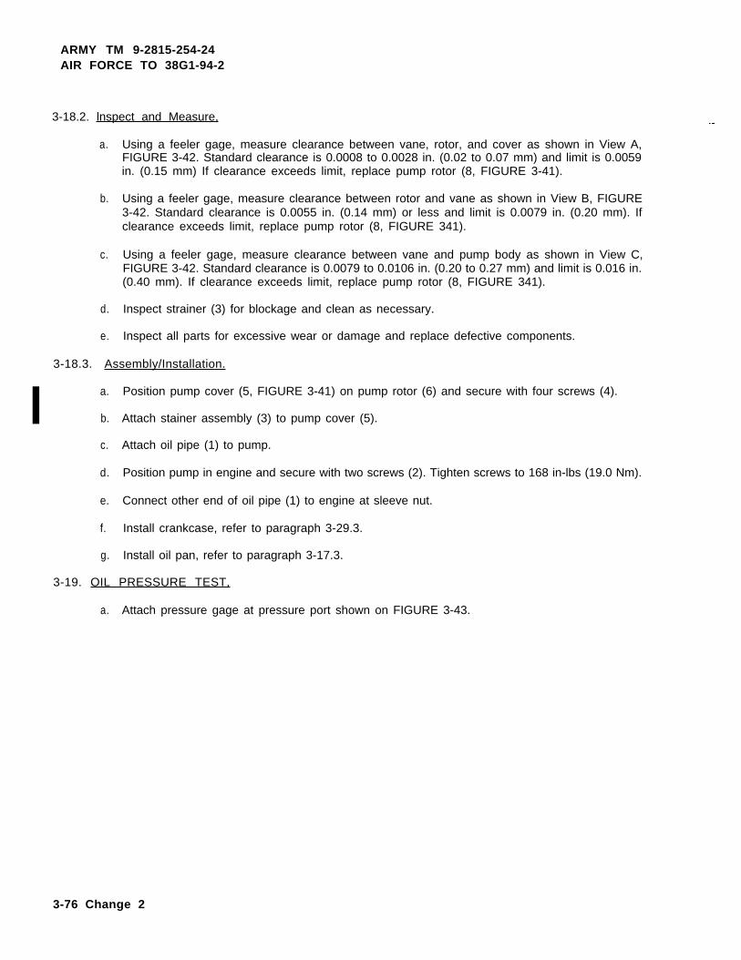
ARMY TM 9-2815-254-24AIR FORCE TO 38G1-94-2
3-18.2. lnspect and Measure,
a. Using a feeler gage, measure clearance between vane, rotor, and cover as shown in View A,FIGURE 3-42. Standard clearance is 0.0008 to 0.0028 in. (0.02 to 0.07 mm) and limit is 0.0059in. (0.15 mm) If clearance exceeds limit, replace pump rotor (8, FIGURE 3-41).
b. Using a feeler gage, measure clearance between rotor and vane as shown in View B, FIGURE3-42. Standard clearance is 0.0055 in. (0.14 mm) or less and limit is 0.0079 in. (0.20 mm). Ifclearance exceeds limit, replace pump rotor (8, FIGURE 341).
c. Using a feeler gage, measure clearance between vane and pump body as shown in View C,FIGURE 3-42. Standard clearance is 0.0079 to 0.0106 in. (0.20 to 0.27 mm) and limit is 0.016 in.(0.40 mm). If clearance exceeds limit, replace pump rotor (8, FIGURE 341).
d. Inspect strainer (3) for blockage and clean as necessary.
e. Inspect all parts for excessive wear or damage and replace defective components.
3-18.3. Assembly/Installation.
a. Position pump cover (5, FIGURE 3-41) on pump rotor (6) and secure with four screws (4).
b. Attach stainer assembly (3) to pump cover (5).
c. Attach oil pipe (1) to pump.
d. Position pump in engine and secure with two screws (2). Tighten screws to 168 in-lbs (19.0 Nm).
e. Connect other end of oil pipe (1) to engine at sleeve nut.
f. Install crankcase, refer to paragraph 3-29.3.
g. Install oil pan, refer to paragraph 3-17.3.
3-19. OIL PRESSURE TEST,
a. Attach pressure gage at pressure port shown on FIGURE 3-43.
3-76 Change 2

VIEW A
ARMY TM 9-2815-254-24AIR FORCE TO 38G1-94-2
VIEW C
FIGURE 3-42. Oil Pump Inspections
VIEW B
3-77

ARMY TM 9-2815-254-24AIR FORCE TO 38G1-94-2
Before checking the oil pressure, warm up engine to allow the lubricat-ing oil to reach operating temperature or high oil pressure readings willoccur.
b. At 850 rpm engine speed and 200°F (93°C) operating temperature, gage should show a minimum pressureof 14 psi (100 kPa).
c. At rated speed (1800 to 2500 rpm) and 220°F (105°C) operating temperature, gage should show a pressurebetween 40 and 70 psi (277 to 483 kPa).
FIGURE 3-43. Oil Pressure Test Setup
3-78
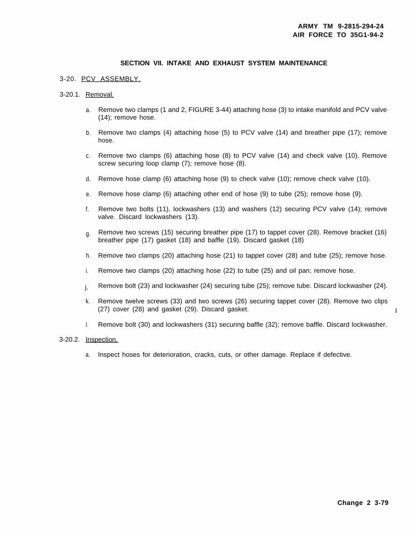
ARMY TM 9-2815-294-24AIR FORCE TO 35G1-94-2
SECTION VII. INTAKE AND EXHAUST SYSTEM MAINTENANCE
3-20. PCV ASSEMBLY.
3-20.1. Removal.
a.
b.
c.
d.
e.
f.
g.
h.
i.
j.
k.
I.
Remove two clamps (1 and 2, FIGURE 3-44) attaching hose (3) to intake manifold and PCV valve(14); remove hose.
Remove two clamps (4) attaching hose (5) to PCV valve (14) and breather pipe (17); removehose.
Remove two clamps (6) attaching hose (8) to PCV valve (14) and check valve (10). Removescrew securing loop clamp (7); remove hose (8).
Remove hose clamp (6) attaching hose (9) to check valve (10); remove check valve (10).
Remove hose clamp (6) attaching other end of hose (9) to tube (25); remove hose (9).
Remove two bolts (11), lockwashers (13) and washers (12) securing PCV valve (14); removevalve. Discard lockwashers (13).
Remove two screws (15) securing breather pipe (17) to tappet cover (28). Remove bracket (16)breather pipe (17) gasket (18) and baffle (19). Discard gasket (18)
Remove two clamps (20) attaching hose (21) to tappet cover (28) and tube (25); remove hose.
Remove two clamps (20) attaching hose (22) to tube (25) and oil pan; remove hose.
Remove bolt (23) and lockwasher (24) securing tube (25); remove tube. Discard lockwasher (24).
Remove twelve screws (33) and two screws (26) securing tappet cover (28). Remove two clips(27) cover (28) and gasket (29). Discard gasket. I
Remove bolt (30) and lockwashers (31) securing baffle (32); remove baffle. Discard lockwasher.
3-20.2. Inspection.
a. Inspect hoses for deterioration, cracks, cuts, or other damage. Replace if defective.
Change 2 3-79
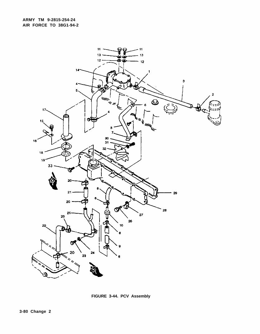
ARMY TM 9-2815-254-24AIR FORCE TO 38G1-94-2
FIGURE 3-44. PCV Assembly
3-80 Change 2

ARMY TM 9-2815-254-24AIR FORCE TO 35G1-94-2
b. Inspect tubes for deformity, cracks, or other damage. Replace if defective.
c. Inspect clamps for deformity, weakness, or other damage. Replace if defective.
d. Inspect check valve for damage. Blow into check valve. At one end, air should pass freely. Atother end, air will not pass through.
3-20.3. Installation.
a.
b.
c.
d.
e.
f.
g.
h.
i.
j.
k.
I.
Position baffle (32, FIGURE 344) and secure with bolt (30) and new lockwasher (31).
Position new gasket (29) tappet cover (28), and two clips (27) on block and secure with twelvescrews (33) and two screws (26) hand tightened. Starting with top center screws and workingalternately top to bottom toward both ends, tighten screws evenly to 168 in-lbs (19.0 Nm).
Position tube (25) on side of engine and secure with bolt (23) and new lockwasher (24).
Attach hose (22) to tube (25) and oil pan and secure with two clamps (20).
Attach hose (21) to tappet cover (28) and tube (25) and secure with two clamps (20).
Position baffle (19) new gasket (18), breather pipe (17) and bracket (16) on tappet cover (28)and secure with two screws (15).
Position PCV valve (14) on engine and secure with two bolts (11), new lockwashers (13) andwashers (12).
Attach one end of hose (9) to tube (25) and secure with clamp (6).
Install check valve (10) in other end of hose (9) and secure with clamp (6).
Attach hose (8) to PCV valve (14) and check valve (10) with two clamps (6). Secure loop clamp(7) to engine with screw.
Attach hose (5) to PCV valve (14) and breather pipe (17) with two clamps (4).
Attach hose (3) to PCV valve (14) and intake manifold with clamps (1) and (2).
Change 2 3-81

ARMY TM 9-2815-254-24AIR FORCE TO 38G1-94-2
3-21. INTAKE AND EXHAUST MANIFOLDS.
3-21.1. Removal.
a.
b.
c.
d.
e.
f.
g.
Remove air intake and exhaust piping, refer to end item maintenance manual.
NOTE
The intake and exhaust manifold must be removed as an assembly.
Remove two bolts (3, FIGURE 3-45) seven nuts (4) lockwashers (5) and washers (6) securingintake manifold (7) and exhaust manifold (8).
Remove two spacers and angle bracket, refer to end item maintenance manual.
Remove clamp (1) and hose (2) to intake manifold.
Remove intake manifold (7) exhaust manifold (8) and gasket (9). Discard lockwashers (5) andgasket (14).
Remove two nuts (10), lockwashers (11), and washers (12) securing inlet pipe (13) to intakemanifold (5). Remove intake pipe and gasket (14). Discard lockwashers (11) and gasket (14).
If damaged, remove studs (15 and 16).
3-21.2. Inspection.
a. Inspect manifolds for cracks, corrosion, or other damage. Replace if damaged.
b. Inspect attaching hardware (bolts, studs, and nuts) for thread damage. Replace if damaged.
3-21.3. Installation.
a. If removed, install studs (15 and 16, FIGURE 345).
b. Position new gasket (14) and inlet pipe (13) on intake manifold (7) and secure with two nuts (10),new lo&washers (11) and washers (12).
3-82
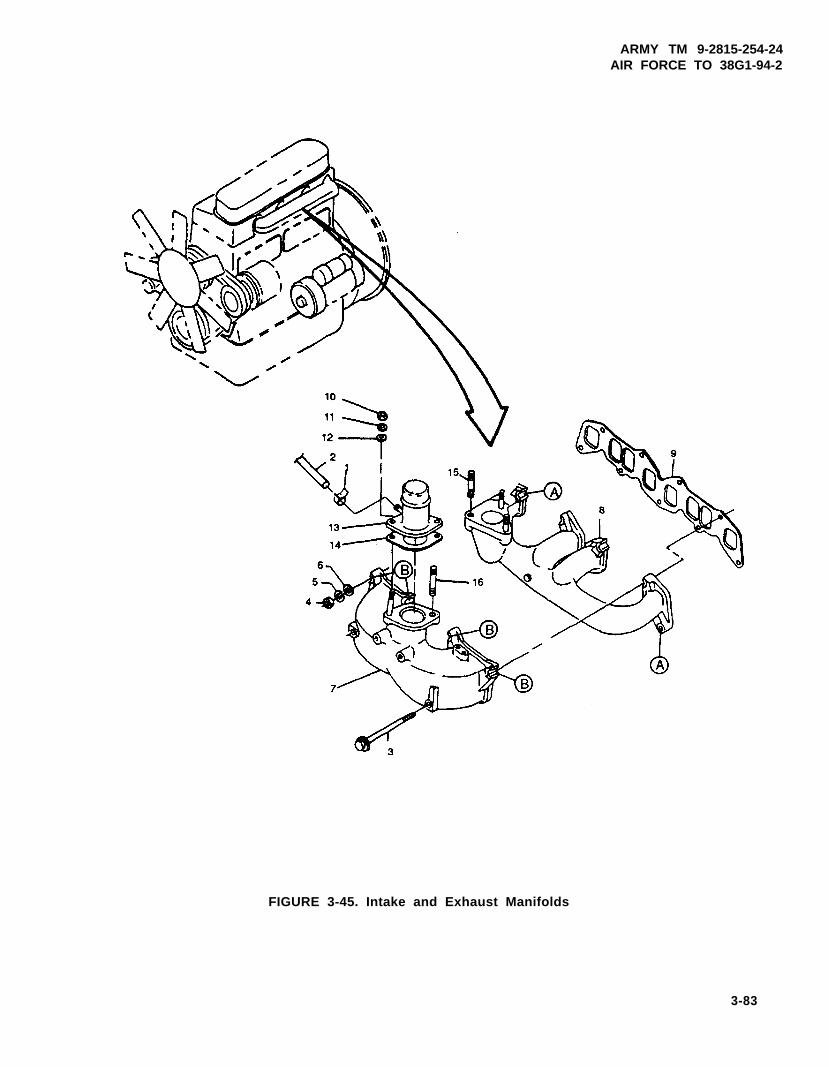
ARMY TM 9-2815-254-24AIR FORCE TO 38G1-94-2
FIGURE 3-45. Intake and Exhaust Manifolds
3-83

ARMY TM 9-2815-254-24AIR FORCE TO 38G1-94-2
c. Clean intake manifold (7) and exhaust manifold (8), mating surfaces, and cylinder head mating surface of anytraces of old gasket.
d. Position new gasket (9) on studs in cylinder head.
NOTE
lntake manifold and exhaust manifold must be installed as an assembly.
e. Position exhaust manifold (8) and intake manifold (7) on studs and secure hand-tight at points ‘A’ and ‘B’ withnuts (4), new lockwashers (5), and washers (6).
f. Install two, bolts (3) hand-tight.
g. Tighten all nuts (4) and bolts (3) to 168 in-lbs (19.0 Nm).
h. Install hose (2) to inlet pipe (13) and secure with clamp (1).
3-84

ARMY TM 9-2815-254-24AIR FORCE TO 35G1-94-2
SECTION VIII. ELECTRICAL SYSTEM
3-22. GLOW PLUGS.
3-22.1. Removal.
a. Loosen nuts on glow plugs and remove connector (1, FIGURE 3-46).
b. Remove glow plugs (2).
3-22.2. Inspection.
a. Inspect electrical leads for cracks, deterioration, cuts, corrosion, or other damage. Replace ifdamaged.
b. Inspect glow plugs for damage to threads or corrosion. Replace if damaged.
NOTE
Always replace all four glow plugs as a set. Never replace just one glow plug.
3-22.3. Testing.
a. Disconnect connector (1) from glow plug.
b. Set multimeter for ohms and connect one lead of multimeter to glow plug terminal and other leadto body.
c. Normal resistance of glow plug is 4.4 to 4.8 ohms. If reading is zero, glow plug is shorted. Ifreading is high, glow plug is open. If shorted or open, replace glow plug.
3-22.4. Installation.
a. Install four glow plugs (2, FIGURE 3-46) in cylinder head. Tighten to 168 in-lbs (19.9 Nm).
b. Install connector (1) by tightening nuts on glow plugs.
3-23. STARTER ASSEMBLY.
3-23.1. Removal.
a. Tag and disconnect electrical leads from starter.
3-85

ARMY TM 9-2815-254-24AIR FORCE TO 38G1-94-2
FIGURE 3-46. Glow Plugs Assembly
b. Support weight of starter and remove two nuts (1, FIGURE 3-47) lockwashers (2) and washers(3). Remove starter from flywheel housing.
c. Cover opening in flywheel.
3-23.2. Disassembly.
a. Benchmark gear case (23, FIGURE 3-47), field coil (24) and housing (11) to aid in aligning partsduring assembly.
b. Disconnect field coil connecting wire from terminal on magnetic switch (5).
c. Remove two bolts (4) securing magnetic switch (5) to gear case (23); remove magnetic switch.
d. Remove two screws (6).
e. Remove two bolts (9) and washers (10).
3-86 Change 2

ARMY TM 9-2815-254-24AIR FORCE TO 35G1-94-2
NOTE
If housing (11) is difficult to separate from field coil (24) tap lightlywith plastic mallet.
f. Remove housing (11) from field coil (24).
g. Remove positive brushes (12) (attached to field coil) from brush holder (15) by raising brushspring (13) and removing brush from holder.
h. Raise springs (13) on negative brushes (14). Raise negative brushes part way off commutatorand hold in this position by setting spring against brush.
i. Remove brusher holder (15).
NOTE
Note installation of shift fork (20) to aid in assembly.
j. Remove nut (16) lockwasher (17) and stud (19) securing shift fork (20) in gear case (23).
k. Remove dust covers (21 and 22).
I. Remove gear case (23).
m. Remove shift fork (20).
n. Remove field coil (24).
NOTE
To remove pinion stopper (26) move stopper toward armature toexpose retainer ring.
o. Remove washer (25) pinion stopper (26) and clutch (27) from armature shaft (18).
p. Remove bracket (28) with center metal (29) from armature shaft.
NOTE
Note from which end of shaft washers (7 and 30) come.
q. Remove thrust washers (7 and 30) from armature shaft.
Change 2 3-87

ARMY TM 9-2815-294-24AIR FORCE TO 38G1-94-2
FIGURE 3-47. Starter Assembly
3-23.3. Testing.
3-23.3.1. Testing Starter (Installed).
a. Make sure batteries are fully charged and that all battery and starter cables are serviceable andproperly installed.
3-88 Change 2

ARMY TM 9-2815-254-24AIR FORCE TO 38G1-94-2
b . Set multimeter for volts DC and as shown in FIGURE 3-48, Test A. If voltage is indicated, solenoid is defective.
FIGURE 3-48. Starter Solenoid Test Circuit
c. Momentarily connect a jumper as shown in FIGURE 3-48, Test B. Multimeter should indicate battery voltageand starter should crank the engine. If multimeter does not read battery voltage, the solenoid is defective.If multimeter indicates battery voltage, but starter does not operate, starter is defective.
3-23.5.2. Testing Starter Components.
a. Test armature for grounds.
(1) Bet multimeter for ohms and touch armature shaft and each commutator bar with multimeter leads.
(2) If multimeter indicates a low reading (approximately zero ohms), armature is grounded and requires re-placing.
b. Test armature for open circuits.
(1) Check for continuity between commutator segments with multimeter.
(2) If an open is indicated, armature must be replaced.
3-89

ARMY TM 9-2815-254-24AIR FORCE TO 38G1-84-2
c. Teat field ceil.
(1) Check for continuity between brushes with a multimeter.
(2) If there is no continuity indicated, field coil is open and field coil frame must be replaced.
(3) Check for continuity between field coil frame and brushes.
(4) If continuity is indicated, field coil is grounded and field coil frame must be replaced.
d. Test solenoid.
(1) Check for continuity between solenoid terminals M and B with a multimeter. Refer to FIGURE 3-48.
(2) No continuity should be indicated when solenoid plunger is in normal (out) position.
(3) Push solenoid plunger in and note multimeter. Multimeter should indicate continuity. If no continuity isindicated, solenoid must be replaced.
3-23.4. Cleaning and Inspection.
Cleaning solvent is flammable and toxic to eyes, akin, and respiratorytract. Skin/eye protection required. Avoid repeated/prolonged contact.Good general ventilation is normally adequate.
Compressed air used for cleaning can create airborne particles thatmay enter the eyes. Pressure will not exceed 30 psig (207 kPa). Eyeprotection required.
3-90

ARMY TM 9-2815-254-24AIR FORCE TO 38G1-94-2
a.
b.
c.
d.
e.
f.
g.
h.
i.
Do not clean overrunning clutch in solvent or other cleaning solution.Washing clutch will remove grease which may result in premature fail-ure of the clutch.
Wipe all metallic parts with a cleaning cloth (TX-1250) that has been slightly dampened with cleaning solvent.
Inspect all parts for damaged threads, cracks, distortion, or other visible damage.
Inspect armature commutator. If commutator is dirty or discolored, clean with abrasive paper (#400). Usecompressed air to blow sand out from between commutator segments.
Inspect commutator for pits, scoring, excessive carbon, and oil. Turn armature commutator in a lathe to re-move surface pits, scoring, and contamination. Normal diameter is 1.89 in. (48.0 mm), minimum after turningis 1.77 in. (45.0 mm). Maximum runout should be 0.016 in. (0.4 mm) Total Indicator Reading (TIR).
Clean around brushes and holders by wiping off all brush dust and dirt. If brushes are shorter than 0.45 in.(11.5 mm) they should be replaced.
Check for free movement of brushes. Brushes should move freely when placed in brush holders. Replacebrush springs if weak or worn.
Inspect brush holders for discoloration, burrs, or signs of high temperature indicating defective insulators.Replace brush holder.
Inspect armature shaft for damage and wear. Replace armature if damaged.
NOTE
If pinion gear is worn or damaged, inspect flywheel ring gear also.
Inspect armature shaft gear, bearings, and pinion gear for wear or damage. Replace any part that is damaged.
3-91

ARMY TM 9-2815-254-24AIR FORCE TO 38G1-94-2
j. When pinion gear/clutch is placed upon armature shaft, pinion gear should turn freely in clockwisedirection and lock when turned in counterclockwise direction.
k. Inspect field coil for damage, bum marks, or wear shown on pole pieces. Replace starter ifdamaged.
323.5. Assembly.
a.
b.
c.
d.
e.
f.
g.
h.
Place two thrust washers (30, FIGURE 3-47) on commutator end of armature (18) and one thrustwasher (7) on other end of armature.
NOTE
When installing rotating or sliding parts, ensure they move smoothly.
NOTE
Thrust washers (30) consist of two washers, one 0.008 in. (0.2 mm) and theother 0.039 in. (1.0 mm) thick. Thrust washer (31) is 0.009 in. (0.25 mm) thick.Thrust on armature is normally 0.004 in. (0.1 mm) to 0.019 in. (0.5 mm). If itexceeds 0.019 in. (0.5 mm) an additional thrust washer is required. Armaturethrust should not be removed completely.
Install center bracket (28) and inside metal (29) on armature shaft.
Install clutch (27) pinion stopper (26) and washer (25) on armature shaft.
Slide armature assembly into field coil (24).
Install shift fork (20) as noted during disassembly.
Install gear case (23).
Secure shift fork (20) with stud (19) new lockwasher (17) and nut (16).
Install dust covers (21 and 22).
3-92 Change 2
ARMY TM 9-2815-254-24AIR FORCE TO 35G1-94-2
i. Position brush holder (15). Use care not to damage negative brushes (14).
j. Lift springs (13) on negative brushes (14) and let brushes rest on commutator. Release springsto apply tension on brushes.
k. Lift springs (13) and insert positive brushes (12) into brush holders. Release springs to applytension on brushes.
I. Position housing (11) on field coil and armature. Align benchmarks made during disassembly.Secure with two bolts (9) and washers (10).
m. Install two screws (6).
n. Position magnetic switch (5) in gear case (23) and secure with two bolts (4).
o. Connect field coil connecting wire to terminal on magnetic switch (5).
3-23.6. Installation.
a. Position starter on flywheel housing engaging clutch (27, FIGURE 3-47) gear teeth with flywheelring gear. Secure starter to flywheel housing with two nuts (1) new lockwashers (2) andwashers (3).
b. Connect electrical leads to starter as tagged during removal.
c. Start engine and check for proper operation.
3-24. ALTERNATOR.
3-24.1. Battery Charging Alternator Test (Installed)
a. Check for battery voltage on alternator between terminals “BAT” and “R” and ground with themaster switch (S1) in the Prime Run Position (Note Voltage).
b. Start Gen Set operator and recheck voltage on alternator terminal Pos Bat and ground for28 + 2 VDC.
3-24.2. Removal.
a. Tag and disconnect electrical leads from alternator.
b. Loosen screw (1, FIGURE 349) and two nuts (4). Pivot alternator to relieve tension on fan beltand remove fan belt from pulley (13).
c. Remove screw (1) and washer (2) securing alternator to bracket (7).
Change 2 3-93

ARMY TM 9-2815-254-24AIR FORCE TO 38G1-94-2
d. Support weight of alternator and remove two bolts (3) washers (6), lockwashers (5) and nuts (4);remove alternator from lower mounting bracket. Discard lockwashers (5).
e. If necessary, remove screw and washer securing bracket (7) to water pump.
3-24.3. Disassembly,
a. Benchmark front cover (10, FIGURE 3-49) stator (25) and rear cover (24) to aid in aligning partsduring assembly.
Ensure stator (25) and rear cover (24) remain together to prevent damage towires connecting stator to rectifier (26).
b. Remove three thru-screws (8 and 9). Remove front cover (10) with rotor (11) from stator (25)and rear cover (24).
c. Clamp rotor (11) in a soft-jawed vise.
d. Remove nut/lockwasher (12) securing pulley (13) to rotor shaft and remove pulley (13).
e. Remove spacer (14) and front cover (10) from rotor.
f. Remove three screws (15) securing retainer (16) to front cover. Remove retainer (16) and bearing(17) from front cover.
NOTE
If bearing (18) is removed from shaft, bearing must be replaced.
g. Remove bearing (18) from rotor shaft.
h. Remove screw (19) nuts (20) nuts (21 and 22) washers (30 and 31) and insulator (23).
i. Carefully remove rear cover (24) from stator (25).
3-94 Change 2
ARMY TM 9-2815-254-24AIR FORCE TO 35G1-94-2
j. Disconnect rectifier (26) wiring from stator using a soldering gun. Melt the solder (SN60WRAP2)quickly and use long-nosed pliers or equivalent to allow for heat dissipation.
k. Disconnect rectifier (26) from brush assembly (28) using a soldering gun. Melt the solder quicklyand use long nosed pliers or equivalent to allow for heat dissipation.
I. Remove bolts (27) from brush assembly (28).
m. Disconnect brush assembly (28) from regulator (29) using a soldering gun. Melt the solder quicklyand use long nosed pliers or equivalent to allow for heat dissipation.
3-24.4. Inspection/Testing,
a. Inspect pulley for cracks and wear.
b. Inspect fan for wear and damaged vanes.
c. Inspect brushes for wear. Normal length is 0.630 in. (16 mm), wear limit is 0.276 in. (7 mm). Ifbelow wear limit, replace brush assembly.
d. Check brush spring tension. Ensure they hold brush tight against slip ring. If weak, replace brushassembly.
e. Inspect/check rotor assembly as follows:
(1)
(2)
(3)
(4)
Measure OD of slip rings. Standard OD is 1.245 in. (31.6 mm) and useable limit is 1.205 in.(30.6 mm). If OD is less than limit, replace rotor.
Check slip ring surface for roughness, oil stain, etc. When surface is rough, use abrasivepaper (#400) to smooth roughness. If dirty or oil stained, wipe clean with alcohol soakedcloth.
Set multimeter for ohms and connect to each slip, ring and check for continuity. Standardrotor coil resistance is 12.72 ohms. If there is no continuity, rotor coil is open and rotor mustbe replaced.
Connect multimeter from one slip ring to shaft. If there is continuity, rotor coil is shorted toground and rotor must be replaced.
Change 2 3-95

ARMY TM 9-2815-264-24AIR FORCE TO 38G1-94-2
FIGURE 3-49. Alternator Assembly
3-96 Change 2

ARMY TM 9-2815-254-24AIR FORCE TO 38G1-94-2
f. Check stator as follows:
(1) Connect multimeter to each set of stator leads and check for continuity. Standard stator coil resistanceis 0.402 ohms. If there is no continuity, stator coil is open and stator must be replaced.
(2) Connect multimeter from stator lead to stator frame. If there is continuity, stator core is shorted to groundand stator must be replaced.
g. Check rectifier as follows:
(1) Check positive side diodes by connecting multimeter positive test probe to each stator terminal and nega-tive test probe to BAT terminal. There should be no continuity. Reverse test probes. There should be con-tinuity.
(2) Check negative side diodes by connecting multimeter positive test probe to each stator terminal and neg-ative test probe to terminal E. There should be continuity. Reverse test probes. There should be no conti-nuity.
(3) If any diode is found to be bad, replace rectifier.
3-24.5. Assembly.
a. When soldering leads, use solder (SN60WRAP2), a 572 to 662°F (300 to 350°C) soldering iron (gun), andcomplete each solder joint within 5 seconds. Use long nosed pliers or equivalent to allow for heat dissipation.
b. Connect regulator (29, FIGURE 3-49) to brush assembly (28) and solder all connections.
c. Press bolts (27) into brush assembly (28) and regulator (29). Pressure required is 221 Ibs (100 kg).
d. Connect rectifier (26) to brush assembly (28) and solder all connections.
e. Connect stator leads to rectifier (26) and solder all connections.
f . Mate stator (25) with end cover (24) aligning benchmarks.
3-97

ARMY TM 9-2815-254-24AIR FORCE TO 38G1-94-2
g.
h.
i.
j.
k.
1..
m.
n.
Install four nuts (20), insulator (23). two nuts (21 and 22), and screw (19). Tighten hardware to 32.5 in-lbs(3.7 Nm).
To keep stator and end cover aligned, place a steel rod through two of the thru-screw holes until ready to insertthru-screws.
Install new bearing (18) on rotor (11) shaft.
Install bearing (17) in front cover (10) . Install retainer (16) and secure with three screws (15). Tighten screwsto 32.5 in-lbs (3.7 Nm).
Install front cover (10) and spacer (14) on rotor (11) shaft.
Clamp rotor (11) in a soft-jawed vise.
Install pulley (13) on rotor shaft and secure with nut/lockwasher (12). Tighten nut to 38 ft-lbs (51.5 Nm).
Use small pin through hole in rear cover to hold brush depressed inbrush holder to allow slip ring to pass through.
Position rotor (11) with front cover (10) attached into stator and rear cover. Align benchmarks, remove twosteel rods, and secure with three thru-screws (8 and 9). Tighten screws to 32.5 in-lbs (3.7 Nm).
3-24.6. Installation.
a. lf removed, position bracket (7, FlGURE 3-49) on water pump mounting and secure with bolt and washer.Tighten bolt to 30 ft-lbs (40.6 Nm).
b. Position alternator on tower mounting bracket and secure with two bolts (3), washers (6). new lockwashers(5), and nuts (4). Do not tighten bolts.
c. Attach alternator to bracket (7) with screw (1) end washer (2).
d. Pivot alternator and route fan belt over pulley (13). Adjust belt tension, refer to end item maintenance manual.
e. Connect electrical leads to alternator as tagged during removal.
f. Operate engine and check for proper operation of electrical system.
3-98

ARMY TM 9-2815-254-24AIR FORCE TO 38G1-94-2
SECTlON IX. ENGINE BLOCK MAINTENANCE
3-25. FRONT GEAR COVER.
3-25.1. Removal.
a. Drain engine lubrication system. Refer to end item maintenance manual.
b. Remove fan and fan belt, refer to end item maintenance manual.
c. Remove four screws (1, FIGURE 3-50) cover (2) and preformed packing (3). Ensure “ZZ’ is still visible.
d. Rotate crankshaft pulley (5) until timing mark is lined up with dial pointer (6), refer to FIGURE 3-6.
NOTE
Ensure engine is at TDC.
e. Remove bolt (4, FIGURE 3-50) securing crankshaft pulley (5) to crankshaft and remove pulley.
f. Remove two screws (7).
g. Support front gear cover (9) and remove thirteen screws (8) attaching cover to engine block; remove cover(9) and preformed pecking (10). Discard preformed packing.
h. Remove dial pointer (6).
i . Remove and discard two preformed packings (11) from front gear cover.
Use care not to damage oil seal fitting surfaces.
i. Remove crankshaft front oil seal (12) from front gear cover using a plastic hammer and a screwdriver to taparound oil seal to free it.
3-25.2. lnspection.
a. Inspect crankshaft front oil seal (12, FIGURE 3-50) for excessive wear, damage, or signs of leakage.
3-99
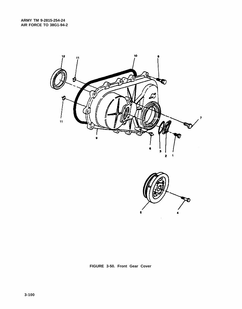
ARMY TM 9-2815-254-24AIR FORCE TO 38G1-94-2
FIGURE 3-50. Front Gear Cover
3-100

ARMY TM 9-2815-254-24AIR FORCE TO 38G1-94-2
b. Inspect crankshaft pulley (5) for cracks and wear.
c. Inspect front gear cover (9) for cracks or other physical damage.
3-25.3. Installation.
a.
b.
c.
d.
e.
f.
g.
Install new crankshaft front oil seal (12, FIGURE 3-50) in front gear cover (9) using oil seal installer(5-6522-9613-0)
Install two new preformed packings (11) in front gear cover.
Install dial pointer (6).
Insert new preformed packing (10) firmly into groove on front gear cover.
Position front gear cover (9) on engine block and secure with thirteen screws (8). Tighten each bolt to 168ftlbs (19.9 Nm) in the sequence shown in FIGURE 3-51.
Install two screws (7).
NOTE
Verify engine is at TDC by viewing “ZZ” mark on timing gear visiblethrough front cover access panel.
Install crankshaft pulley (5, FIGURE 3-50) on crankshaft, aligning mark on pulley with pointer and secure withbolt (4). Tighten bolt to 137 ft-Ibs (166.0 Nm).
FIGURE 3-51. Front Gear Cover Screw lightening Sequence
3-101

ARMY TM 9-2815-254-24AIR FORCE TO 38G1-94-2
h. Install new preformed gasket (3) and cover (2). Secure cover (2) with four screws (1).
i. Install fan belt and fan, refer to end item maintenance manual.
j . Service engine lubrication system, refer to end item maintenance manual.
3-26. ROCKER COVER AND ARMS.
3-26.1. Removal.
a. Remove PCV assembly as required to access rocker cover, refer to paragraph 3-20.1.
NOTE
Rocker arm shaft (18) positioning is done by a cutaway machined onshaft end. Install retaining plates (13) and shaft (18) so that cutawayfaces mating bolt stem.
NOTE
Rocker arms (12, 14, 16, and 17) each have a different shape. Be sureto install them in their correct location (refer to Figures 3-52 and 3-53)as viewed from front.
b. Remove two bolts (1, FIGURE 3-52) washers (2), and gaskets (3) securing rocker cover (5); remove rockercover (5) and preformed packing (6). Discard two gaskets (3) and preformed packing (6).
c. Loosen eight nuts (19) and loosen adjusting screws (20) until the adjusting screws (20) just touch pushrods.
d. Remove valve rocker oil feed pipe, refer to paragraph 3-16.1.
Failure to loosen retainer plate bolts (7) a little at a time in the propersequence, will adversely affect rocker arm shaft (18).
e. Loosen eight bolts (7) a little at a time in the sequence shown in FIGURE 3-53.
f. After all bolts have been loosened, remove eight bolts (7, FIGURE 3-52) and washers (8). Remove rockerarm assembly.
3-26.2. Disassembly.
a. Remove two retaining rings (9, FIGURE 3-52) and washers (10) from each end of shaft (18).
b. Remove eight rocker arms (12, 14, 16, and 17) four retaining plates (13) and three springs (15) from shaft(18).
3-102

ARMY TM 9-2815-254-24AIR FORCE TO 38G1-94-2
FIGURE 3-52. Rocker Covet and Arms
3-103

ARMY TM 9-2815-254-24AIR FORCE TO 38G1-94-2
FIGURE 3-53. Rocker Arm Retaining Plate Bolt Loosening Sequence
c. Remove nut (19) and adjusting screw (20) from each rocker arm.
d. Remove dust cap (11) from each end of shaft (18).
3-26.3. Inspect and Measure.
a. Check rocker arm shaft (18, FIGURE 3-52) run-out as follows:
(1) Place rocker arm shaft on V-blocks, refer to FIGURE 3-54.
FIGURE 3-54. Rocker Arm Shaft Runout
3-104

ARMY TM 9-2815-254-24AIR FORCE TO 38G1-94-2
(2) Use a dial indicator to measure shaft central portion run-out. Limit on run-out is 0.024 in. (0.6 mm). If run-out exceeds limit, replace shaft. If run-out is very slight, an arbor press may be used to correct shaft. Shaftmust be cold.
b. Use a micrometer and measure rocker arm shaft outside diameter, refer to FIGURE 3-55. The standard diam-eter is 0.747 to 0.748 in. (18.98 to 19.0 mm), with a limit of 0.744 in. (18.90 mm). If measured value is lessthan limit, replace rocker arm shaft (18, FIGURE 3-52).
FIGURE 3-55. Rocker Arm Shaft Outside Diameter
c. Use either a vernier caliper or a dial indicator and measure rocker arm (12, 14, 16, and 17, FIGURE 3-52)bushing inside diameter. The standard diameter is 0.749 to 0.750 in. (19.036 to 19.060 mm), with a limit of0.752 in. (19.10 mm). lf measured value exceeds limit, replace rocker arm.
d. Clearance between rocker arm shaft 00 and rocker arm bushing ID standard value is 0.0016 in. (0.04 mm).If clearance exceeds 0.008 in. (0.20 mm), replace either rocker arm shaft (18) or rocker arm (12, 14, 16, and17).
3-105

ARMY TM 9-2815-254-24AIR FORCE TO 3861-94-2
Compressed air used for cleaning can create airborne particles thatmay enter the eyes. Pressure will not exceed 30 psig (207 kPa). Eyeprotection required.
e. Check that rocker arm oil ports (two) are free of obstructions. refer to FIGURE 3-56. Use compressed air ifnecessary to clean oil ports.
FIGURE 3-56. Rocker Arm Oil Ports, Location of
f. Inspect rocker arm valve stem contact surface for step wear and storing. If contact services have light step wear or scoring, they may be honed with oil stone. If step wear or scoring is severe, rocker arm must be replaced, refer to FIGURE 3-57.
3-26.4. Assembly.
Compressed air used for cleaning can create airborne particles thatmay enter the eyes. Pressure will not exceed 30 psig (207 kPa). Eyeprotection required.
3-106
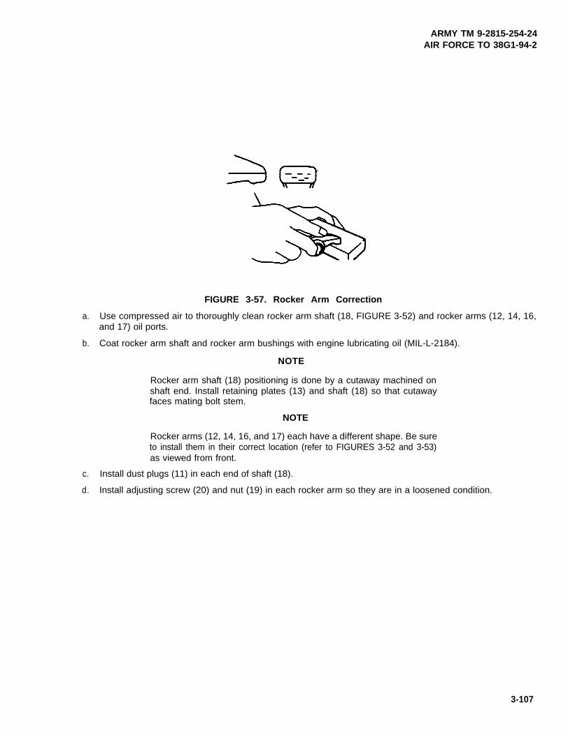
ARMY TM 9-2815-254-24AIR FORCE TO 38G1-94-2
FIGURE 3-57. Rocker Arm Correction
a. Use compressed air to thoroughly clean rocker arm shaft (18, FIGURE 3-52) and rocker arms (12, 14, 16,and 17) oil ports.
b. Coat rocker arm shaft and rocker arm bushings with engine lubricating oil (MIL-L-2184).
NOTE
Rocker arm shaft (18) positioning is done by a cutaway machined onshaft end. Install retaining plates (13) and shaft (18) so that cutawayfaces mating bolt stem.
NOTE
Rocker arms (12, 14, 16, and 17) each have a different shape. Be sureto install them in their correct location (refer to FIGURES 3-52 and 3-53)as viewed from front.
c. Install dust plugs (11) in each end of shaft (18).
d. Install adjusting screw (20) and nut (19) in each rocker arm so they are in a loosened condition.
3-107

ARMY TM 9-2815-254-24AIR FORCE TO 38G1-94-2
NOTE
Back end of shaft (18) is the end with the oil supply hole.
e . Install retaining ring (9) and washer (10) on one end of shaft (18). This will be back end of shaft (in relationto engine).
f . Installone rocker arm (12), three rocker arms (14) three rocker arms (16), one rocker arm (17), four retainingplates (13) and three springs (15) following the sequence shown in FIGURES 3-52 and 3-53. Start with rockerarm (12) and finish with rocker arm (17) (front of engine). Retaining plates are marked with an ‘F and thisside must face the front of engine.
g. Install washer (10) and retaining ring (9) on end of shaft (18)
3-26.5. Installation.
a. Position rocker arm assembly on cylinder head and secure four retaining plates (13, FIGURE 3-52) with twobolts (7) and washers (8) each. Tighten bolts to 168 in-lbs (19.0 Nm) in sequence shown in FIGURE 3-58.
FIGURE 3-58. Rocker Arm Retaining Plate Bolt Tightening Sequence
3-108

ARMY TM 9-2815-254-24AIR FORCE TO 38G1-94-2
b. Install PCV assembly, refer to paragraph 3-20.3.
c. Install valve rocker oil feed pipe, refer to paragraph 3-16.2.
d. Perform adjustment procedures, refer to paragraph 3-26.6.
e. Position new preformed packing (6) and rocker cover (5) on cylinder head and secure with two bolts (1), wash-ers (2) and new gaskets (3). Tighten bolts to 114 in-lbs (13.0 Nm)
3-26.6. Adjustment.
a. Remove rocker cover (5, FIGURE 3-52) if not already removed, refer to paragraph 3-26.1.
b. Ensure all eight retaining plate bolts (7) are tight. If not, tighten in accordance with paragraph 3-26.5.
c. Rotate crankshaft until crankshaft pulley TDC line is aligned with timing pointer. This will bring piston in No.1 or No. 4 cylinder to TDC on compression stroke.
d. Check for play in No. 1 intake and exhaust valve push rods. If push rods have play, No. 1 piston is at TDCon compression stroke. If push rods are depressed, No. 4 piston is at TDC on compression stroke.
e. Adjust valve clearance for rocker arms shown in View A of FIGURE 3-59 as follows:
(1) Loosen nut (19, FIGURE 3-52) and adjusting screw (20).
VIEW A VIEW B
FIGURE 3-59. Valve Clearance Adjustment Sequence
3-109

ARMY TM 9-2815-254-24AIR FORCE TO 38G1-94-2
(2) Insert a 0.018 in. (0.45 mm) feeler gage between rocker arm and end of valve stem.
(3) Turn adjusting screw (20) until a slight drag is felt on feeler gage.
(4) Tighten nut (19).
f. Rotate crankshaft 360 degrees until crankshaft pulley TDC fine is aligned with timing pointer.
g. Adjust valve clearance for rocker arms shown in View B of FIGURE 3-59 as described in step e.
h. Install rocker cover (5, FIGURE 3-52) refer to paragraph 3-26.5.
3-27. CYLINDER HEAD ASSEMBLY.
3-27.1. Removal.
Do not drain coolant until coolant temperature is below operating tem-perature. Scalding can occur from failure to observe this warning.
a. Drain engine coolant and lubrication systems, refer to end item maintenance manual.
b. Remove thermostat housing, refer to paragraph 3-6.1.
c. Remove fuel injector nozzles and piping, refer to paragraph 3-10.1.
d. Remove glow plugs, refer to paragraph 3-22.1.
e. Remove intake and exhaust manifolds, refer to paragraph 3-21.1.
f. Remove rocker cover and rocker arms, refer to paragraph 3-28.1.
g. Remove eight pushrods (1, FIGURE 3-60).
3-110

ARMY TM 9-2815-254-24AIR FORCE TO 38G1-94-2
FIGURE 3-60. Cylinder Head Assembly
3-111

ARMY TM 9-2815-254-24AIR FORCE TO 38G1-94-2
Failure to loosen cylinder head bolts (2) a little at a time and in the propersequence will adversely affect cylinder head (3) lower surface.
h. Loosen nineteen bolts (2) a file at a time in the sequence shown in FIGURE 3-61.
i. After all nineteen bolts (2, FIGURE 3-60) have been loosened, remove them and lift cylinder head assembly(3) from engine block. Remove and discard head gasket (4).
FIGURE 3-61. Cylinder Head Bolt Loosening Sequence
3-27.2. Disassembly.
a. Place cylinder head on a flat wooden surface.
To avoid personal injury, do not stand in front of valve springs while com-pressing them.
3-112

ARMY TM 9-2815-254-24AIR FORCE TO 38G1-94-2
Do not allow valves (10 and 11, FIGURE 3-60) to fall from bottom of cylinder head.
b. Use spring compressor to compress springs (8 and 9) and remove spring lock (5).
c. Release spring compressor and remove seat assembly (6), sealing ring (7). and springs (8 and 9) from valvestem.
d. Repeat steps b and c for remaining seven valves.
N O T E
If valves are to be reused, tag them with cylinder number from whichthey were removed. If they are to be replaced, valve guides must alsobe replaced.
e. Remove eight valves (10 and 11).
f. Remove eight valve seals (12) from valve guides (16).
g. Remove hot plugs (13) as follows:
(1) Refer to FIGURE 3-62 and insert a 0.12 to 0.20 in. (3.0 to 5.0 mm) diameter brass bar into fuel injectorfifing until it makes contact with hot plug (13, FIGURE 3-60).
(2) Lightly tap bar with a hammer to drive hot plug free.
FIGURE 3-62. Hot Plug Removal
3-113

ARMY TM 9-2815-254-24AIR FORCE TO 36G1-94-2
h. After hot plug has been removed, use hammer and same brass bar through hot plug hole to lightly tap lowerside of heat shield (14) and drive it free. Remove heat shield (14) and washer (15).
i . Remove valve guides (16) using a hammer and valve guide replacer (NU-7634) to drive out guides from lowerface of cylinder heed.
j. Remove valve seat inserts (17 and 18) as follows:
(1) Using MIG welder (refer to TM 9-239) weld four spots evenly spaced to inside circumference of valveseat insert. These will be used to pry insert free.
(2) Allow it to cool for a few minutes which will cause contraction and make removal easier.
Use care not to damage cylinder head.
(3) Use a screwdriver and pry valve seat insert free.
(4) Carefully remove carbon and other foreign material from cylinder head insert bore.
3-27.3. Inspect and Measure.
a. Check cylinder head lower face warpage as follows:
(1) Use a straight edge and feeler gage to measure the four sides and two diagonals of cylinder head lowerface, refer to FIGURE 3-63.
FIGURE 3-63. Cylinder Head Inspection
3-114

ARMY TM 9-2815-254-24AIR FORCE TO 38G1-94-2
(2) Standard warpage should be 0.002 in. (0.05 mm) or less.
(3) Regrind cylinder head lower face if measurement values are greater than warpage limit of 0.008 in. (0.2mm), but less than maximum grinding limit of 0.012 in. (0.30 mm)
(4) If warpage exceeds maximum grinding limit, cylinder head must be replaced.
(5) Standard cylinder height as measured on fuel injector side of head is 3.620 to 3.624 in. (91.95 to 92.05mm), with a limit of 3.612 in. (91.75 mm), refer to FIGURE 3-64.
FIGURE 3-64. Cylinder Head Height (Reference)
(6) If cylinder head lower face is reground, valve depression must be checked in accordance with step h.
b. Check hot plug depression as follows:
(1) Clean cylinder head lower face, using care not to damage hot plug surfaces, refer to FIGURE 3-65.
(2) Use a straight edge and feeler gage to measure hot plug depression in a straight line from No. 1 to No.4 hot plug.
(3) If measured value exceeds 0.0008 in. (0.02 mm), replace hot plugs.
3-115
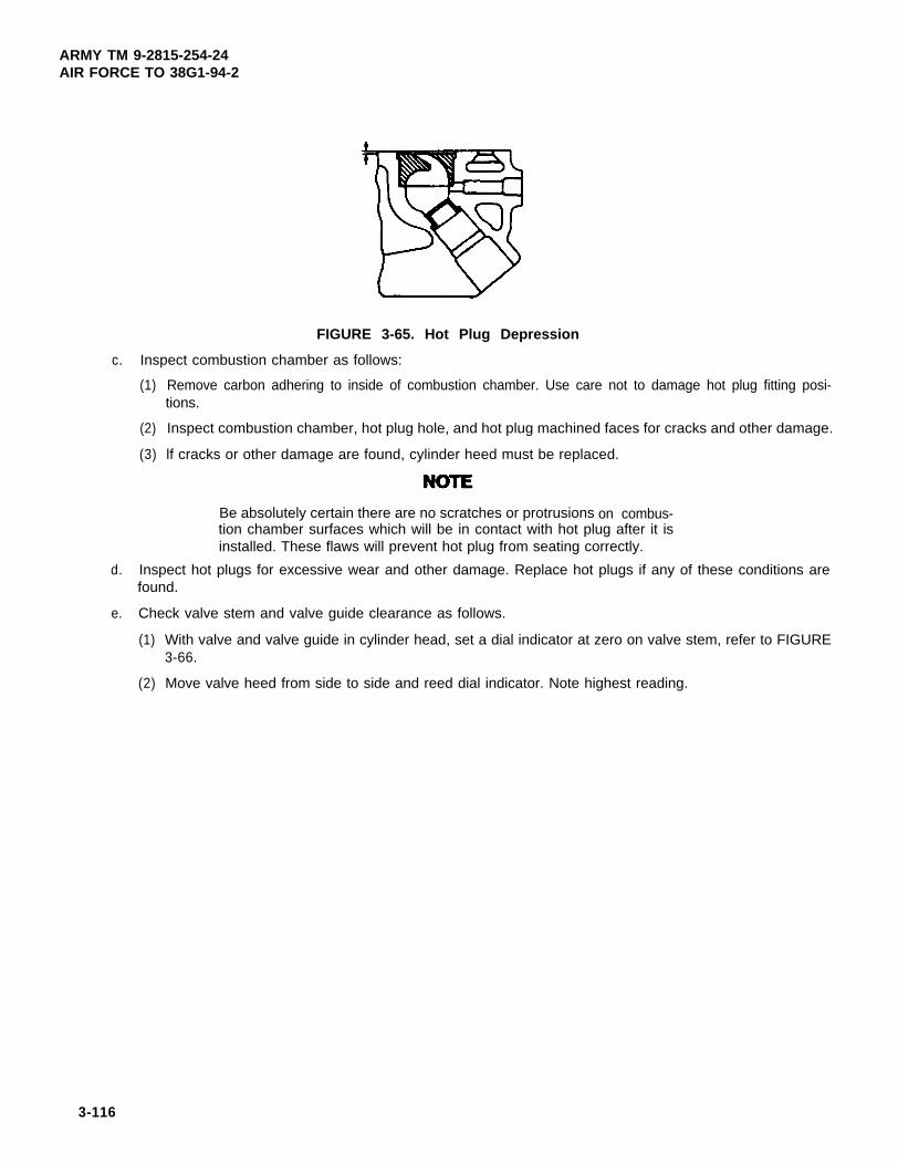
ARMY TM 9-2815-254-24AIR FORCE TO 38G1-94-2
FIGURE 3-65. Hot Plug Depression
c. Inspect combustion chamber as follows:
(1) Remove carbon adhering to inside of combustion chamber. Use care not to damage hot plug fitting posi-tions.
(2) Inspect combustion chamber, hot plug hole, and hot plug machined faces for cracks and other damage.
(3) lf cracks or other damage are found, cylinder heed must be replaced.
Be absolutely certain there are no scratches or protrusions on combus-tion chamber surfaces which will be in contact with hot plug after it isinstalled. These flaws will prevent hot plug from seating correctly.
d. Inspect hot plugs for excessive wear and other damage. Replace hot plugs if any of these conditions arefound.
e. Check valve stem and valve guide clearance as follows.
(1) With valve and valve guide in cylinder head, set a dial indicator at zero on valve stem, refer to FIGURE3-66.
(2) Move valve heed from side to side and reed dial indicator. Note highest reading.
3-116

ARMY TM 9-2815-254-24AIR FORCE TO 3861-94-2
FIGURE 3-66. Valve Stem and Guide Clearance
(3) If measured values exceed specified limit, valve and valve guide must be replaced as a set.
(4) Intake valve stem clearance standard is 0.0015 to 0.0027 in. (0.039 to 0.069 mm), with a limit of 0.008in. (0.20 mm). Exhaust valve stem clearance standard is 0.0025 to 0.0037 in. (0.084 to 0.093 mm), witha limit of 0.0098 in. (0.25 mm).
f. Check valve stem outside diameter as follows:
(1) Using a micrometer, measure valve stem OD at three points, refer to FIGURE 3-67.
FIGURE 3-67. Valve Stem Outside Diameter
3-117

ARMY TM 9-2815-254-24AIR FORCE TO 38G1-94-2
(2) If measured value is less than limit, replace valve and valve stem as a set.
(3) Intake valve stem standard OD is 0.3129 to 0.3134 in. (7.949 to 7.961 mm), with a limit of 0.3102 in. (7.88mm). Exhaust valve stem standard OD is 0.3118 to 0.3124 in. (7.921 to 7.936 mm), with a limit of 0.3090in. (7.85 mm)
g. Check valve thickness, refer to FIGURE 3-68. Standard measurement is 0.05 in. (1.3 mm), with a limit of 0.04in. (1.0 mm). If measured value is less than limit, replace valve and valve guide as a set.
FIGURE 3-68. Checking Valve Thickness
h. Check valve depression as follows:
(1) Install valve in cylinder head, refer to FIGURE 3-69.
FIGURE 3-69. Valve Depression
3-118

ARMY TM 9-2815-254-24AIR FORCE TO 38G1-94-2
(2) Use a depth gage or straight edge with steel rule to measure valve depression from cylinder head lowersurface.
(3) The standard depression is 0.028 in. (0.7 mm), with a limit of 0.11 in. (2.7 mm). If depression exceedslimit, replace valve seat insert.
i. Check valve contact width as follows:
(1) Check valve contact faces for roughness and unevenness. Smooth contact surfaces as necessary.
(2) Using blue bearing dye (HISPOTBLUE 107), coat valve seat insert. Install valve and rotate valve to pickupchalk on valve.
(3) Measure valve contact width. Refer to FIGURE 3-70. Standard width is 0.05 to 0.06 in. (1.2 to 1.5 mm),with a limit of 0.08 in. (2.0 mm).
(4) If measured value exceeds limit, replace valve seat insert.
FIGURE 3-70. Checking Valve Contact Width
j. Check valve spring free length using a vernier caliper, refer to FIGURE 3-71. Standard height of inner springis 1.89 in. (47.9 mm), with a limit of 1.83 in. (46.5 mm). Standard height of outer spring is 1.86 in. (47.3 mm),with a limit of 1.80 in. (45.8 mm). If measured value is less than limit, replace spring.
k. Check valve spring inclination using a surface plate and a square. lf inclination measured exceeds 0.04 in.(1.0 mm), replace spring.
3-119

ARMY TM 9-2815-254-24AIR FORCE TO 38G1-94-2
FIGURE 3-71. Valve Spring Free! Height
I . Check valve spring tension as follows:
(1) Install spring in spring tester, refer to FIGURE 3-72. Compress innerspring to 1.46 in. (37.0 mm) or outerspring to 1.54 in. (39.0 mm).
(2) Standard pressure to compress inner spring is 12.21 to 13.78 Ibs (5.55 to 6.25 kg), with a limit of 11.03lbs (5.0 kg). Standard pressure to compress outer spring is 43.33 to 48.84 lbs (19.65 to 22.15 kg). witha limit of 39.69 lbs (18.0 kg)
(3) If pressure required to compress spring is less than limit, replace spring.
FIGURE 3-72. Valve Spring Tension
3-120

ARMY TM 9-2815-254-24AIR FORCE TO 38G1-94-2
m. Check pushrod curvature as follows:
(1) Lay pushrod on a surface plate, refer to FIGURE 3-73.
NOTE
If surface plate is not available, use a flat surface.
(2) Roll pushrod along surface plate checking for curvature with a thickness gage.
(3) If measured value exceeds 0.012 in. (0.3 mm), replace pushrod.
(4) Inspect both ends of pushrod for excessive wear or damage. If excessive wear or damage is found, re-place pushrod.
FIGURE 3-73. Push Rod Curvature
n. Inspect studs (22, FIGURE 3-60) for stripped threads or other damage.
o. Inspect freeze plugs (23, 24, 25, and 26) and dust plug (27) for cracks and other damage.
3-27.4. Repair.
a. Correct valve seat insert as follows:
(1) Remove carbon from valve seat insert surface.
3-121

ARMY TM 9-2815-254-24AIR FORCE TO 38G1-94-2
(2) Use a valve cutter (15, 45, and 75 degree blades) to minimize scratches and other rough areas. This willbring contact width back to standard value, refer to FIGURE 3-74.
(3) Remove only scratches and rough areas. Do not cut away too much. Take care not to cut away unblem-ished areas of valve seat surface.
NOTE
Use an adjustable valve cutter pilot. Do not allow it to wobble inside valve guide.
(4) Apply lapping compound (SSL1682) to valve seat insert surface.
(5) Insert valve into valve guide.
(6) Turn valve while tapping it to fit valve seat insert.
(7) Check that valve contact width is correct.
(8) Check that valve seat insert surface is in contact with entire circumference of valve.
FlGURE 3-74. Valve Seat Correction
b. Replace damaged studs (22, FIGURE 3-60) freeze plugs (23, 24, 25, and 26), and duet plug (27).
3-122

ARMY TM 9-2815-254-24AIR FORCE TO 38G1-94-2
3-27.5. Assembly.
a. Install valve seat inserts (17 and 18, FIGURE 3-60) as follows:
(1) Place valve seat insert in position and carefully place attachment (1, FIGURE 3-75), having a smaller ODthan valve seat insert, on valve seat insert (2).
NOTE
Smooth side of attachment must contact insert.
Do not apply an excessive amount of pressure with press. Damage tovalve seat insert will result.
(2) Use an arbor press (3) to gradually apply pressure to attachment and press valve seat insert into place.
NOTE
Valve seat insert may need to be ground to obtain proper contact width.Refer to paragraph 3-27.4.
FIGURE 3-75. Valve Seat Insert Installation
3-123

ARMY TM 9-2815-254-24AIR FORCE TO 38G1-94-2
b. Install valve guides (16, FIGURE 3-60) as follows:
(1) Apply engine lubricating oil (ML-L-2104) to valve guide outer circumference.
(2) Attach valve guide installing tool (NU-7634) and valve guide setting tool (320908) to valve guide.
(3) Use a hammer to drive valve guide into position from cylinder head upper face.
(4) Measure distance valve guide extends above cylinder head upper face. Distance should be approximate-ly 0.47 in. (12.0 mm).
NOTE
If valve guide has been removed, valve and valve guide must be re-placed as a set.
c. Install heat shields (14, FIGURE 3-60) as follows:
NOTE
Always install a new heat shield (14). Never reuse an old heat shield(14).
(1) Position washer (15) and heat shield (14), flange side facing up, in cylinder head through fuel injector hole.
(2) Lightly tap heat shield flange into place with a hammer and a brass bar.
d . Install used hot plugs (13) as follows:
(1) Align hot plug knock ball with cylinder head groove.
(2) Use a plastic hammer lo tap hot plug into place.
e. Install new hot plugs (13) as follows:
(1) Align hot plug knock ball with cylinder head groove and using a plastic hammer tap it temporarity into posi-tion.
3-124

ARMY TM 9-2815-254-24AIR FORCE TO 38G1-94-2
(2) Place a 1.0 in. (25 mm) thick metal plate over hot plug upper surface.
Do not apply pressure greater than specified. Damage to cylinder headwill result.
(3) Use an arbor press to exert a pressure of 9923 to 12,128 Ibs (4500 to 5500 kg) on metal plate. This willdrive hot plug into position.
(4) Using plastic hammer, lightly tap hot plug head to ensure it is firmly seated.
(5) Repeat steps (1) through (4) for other hot plugs.
(6) Hot plug surfaces must be perfectly flush with cylinder head lower face. Use a surface grinder to grindoff any hot plug surface protrusions.
(7) After grinding, ensure hot plug surfaces are completely free of protrusions. Ensure there are no hot plugdepressions.
(8) Tap each hot plug heed lightly to ensure they are firmly seated.
f. Apply a coat of engine lubricating oil (MIL-L-2104) to inner face of seal (12) and using oil seal installer, installoil seal (12) to valve guides.
g. Apply a coat of engine lubricating oil (MIL-L-2104) to valve stems and install eight valves (10 and 11) in cylin-der head.
h. Install springs (8 and 9) with their fine pitched end (painted) facing down, sealing ring (7) and seat assembly(6) on valve stem.
i. Use spring compressor to compress springs and install two piece spring lock (5).
i. Repeat steps h and i for remaining seven valves.
3-27.6. Installation.
a. Place new head gasket (4, FIGURE 3-60) on engine block with word TOP facing up.
3-125

ARMY TM 9-2815-254-24AIR FORCE TO 38G1-94-2
b. Carefully place cylinder head (3) on engine block aligning engine block dowels with cylinder head dowel holes.
c. Lubricate nineteen bolts (2) with engine lubricating oil (MIL-L-2104) and install them hand tight.
d. Tighten bolts (2) in two steps following sequence shown in FIGURE 3-76.
(1) Step 1 - New bolts - 47.0 ft-lbs
(63.7 Nm)
- Used bolts - 47.0 ft-lbs(63.7 Nm)
(2) Step 2 - New bolts - 58 ft-lbs(78 Nm)
- Used bolts - 65.0 ft-lbs(88.3 Nm)
e. Lubricate ends of pushrods (1, FIGURE 3-60) with engine lubricating oil (MIL-L-2104) and install eight push-rods.
FIGURE 3-76. Cylinder Head Bolt Tightening Sequence
f. Install rocker arms, refer to paragraph 3-26.5.
g. Install intake and exhaust manifolds, refer to paragraph 3-21.3.
h. Install glow plugs, refer to paragraph 3-22.4.
i . Install fuel injector nozzles and piping, refer to paragraph 3-10.7.
j . Install thermostat housing, refer to paragraph 3-6.4.
3-126

ARMY TM 9-2815-254-24AIR FORCE TO 38G1-94-2
k. Service engine coolant and lubrication systems, refer to end item maintenance manual and lubrication order.
3-27.7. Compression Check.
a. Start engine and allow it to warm up until coolant temperature is above 176°F (80°C).
b. Shut down engine.
c. Remove glow plug from No. 1 cylinder.
d. Connect adapter (J-26999-2) and compression gage (MIL-T-2764) to No. 1 cylinder glow plug hole.
e. Turn engine over with starter and record compression gage reading. Standard compression at 200 rpm andat sea level is 441 psi (3038 kPa), with a limit of 327 psi (2254 kPa)
f. Repeat steps b through e for each cylinder.
g. If compression is less then limit, troubleshoot the engine.
3-28. PISTONS, CONNECTING RODS, AND CRANKSHAFT
3-28.1. Removal.
a. Remove oil filter, refer to paragraph 3-14.2.
b. Remove fuel filter, refer to paragraph 3-9.1.
c. Remove starter, refer to paragraph 3-23.1.
d. Remove alternator, refer to paragraph 3-24.1.
e. Remove water pump, refer to paragraph 3-7.1.
f. Remove PCV system, refer to paragraph 3-20.1.
g. Remove oil pan, refer to paragraph 3-17.1.
h. Remove front gear cover, refer to paragraph 3-25.1.
i. Remove idler gear and shaft, refer to paragraph 3-30.1.
j. Remove fuel injection pump, refer to paragraph 3-11.1.
k. Remove cylinder heed, refer to paragraph 3-27.1.
I. Remove crankcase, refer to paragraph 3-29.1.
3-127

ARMY TM 9-2815-254-24AIR FORCE TO 38G1-94-2
m. Remove oil pump refer to paragraph 3-18.1.
n. Remove carbon deposits from upper portion of cylinder wall with a scraper before removing piston and con-necting rod.
o. Remove two bolts (1, FIGURE 3-77) and nuts (2) securing connecting rod bearing cap (3). Remove lowerhalf d bearing cap (3) and connecting rod bearings (4).
N O T E
If connecting rod hearings are to be reused, tag them as to their originalposition to facilitate installation.
p. Move piston (5) to top of cylinder and tap it with a hammer handle or similar object, from connecting rod side,to drive it out of cylinder.
q. Repeat steps n through p for remaining pistons and connecting rode.
r. Remove camshaft, refer to paragraph 3-30.1.
s. Remove flywheel and flywheel housing, refere to paragraph 3-31.1.
t. Remove screws (6), front plate (7), and gasket (8). Discard gasket.
Use care not to scratch crankshaft oil seal seating surfaces.
u. Remove rear oil seal and spacer.
v. Measure crankshaft end play at the center journal, refer to FIGURE 3-78. Do this before removing bearingcaps. Standard end play is 0.004 in. (0.10mm), with a Iimit of 0.012 in. (0.30mm). If measured value exceedslimit, crankshaft thrust bearings (9) must be replaced.
N O T E
lf crankshaft bearing cap bolts and bearings are to be reused, tag themas to their original locations to facilitate installation.
3-128

ARMY TM 9-2815-254-24AIR FORCE TO 38G1-94-2
FIGURE 3-77. Pistons, Connecting Rods, and Crankshaft
3-129

ARMY TM 9-2815-254-24AIR FORCE TO 38G1-94-2
FIGURE 3-78. Crankshaft End Play
w. Loosen ten crankshaft baring cap bolts a little at a time in sequence shown in FIGURE 3-79.
FIGURE 3-79. Crankshaft Bearing Cap Bolt Loosening Sequence
X. Remove ten bolts, five sets of bearings (10), two thrust bearings (9), and crankshaft from engine block.
3-130

ARMY TM 9-2815-254-24AIR FORCE TO 38G1-94-2
3-28.2. Disassembly.
a Clamp piston connecting rod (14, FIGURE 3-77) in a softjawed vise.
Do not attempt to use some other tool to remove piston rings. Pistonring stretching will result in reduced piston ring tension.
b. Use a piston ring expander to remove four piston rings (11) from piston (5).
c. Remove two retainer rings (12) from piston pin (13).
N O T E
If piston and piston pin are to be reused, tag each piston and pin withcylinder number from which it was removed.
d. Using a hammer and a brass bar, tap piston pin (13) from piston (5)
e. Remove deflector (15) from crankshaft.
f. Using gear puller, remove crankshaft gear (16) from crankshaft. Remove key (17).
3-28.3. Inspect and Measure
3-28.3.1. Piston and Connecting Rod.
a. Check piston ring and piston ring groove clearance as follows:
(1) Using a feeler gage, measure the clearance between piston ring and piston ring groove at several pointsaround the piston, refer to FIGURE 3-80.
(2) Standard clearance for the three compression rings is 0.0017 to 0.0027 in. (0.045 to 0.070 mm). Standardclearance for the oil ring is 0.0008 to 0.0021 in. (0.020 to 0.055 mm). The limit for clearance is 0.0059in. (0.15 mm)
(3) If clearance exceeds limit, replace piston rings.
3-131

ARMY TM 9-2815-254-24AIR FORCE TO 38G1-94-2
FlGURE 3-80. Piston Ring and Groove Clearance
b. Check piston ring gap as follows:
(1) Insert a piston ring horizontally (in position as installed on piston), into cylinder liner bore, refer to FIGURE3-81.
FIGURE 3-81. Piston Ring
3-132

ARMY TM 9-2815-254-24AIR FORCE TO 38G1-94-2
(2)
(3)
(4)
Using an inverted piston, push piston ring into cylinder liner approximately 0.39 in. (10 mm) or to the pointwhere diameter of liner is smallest.
Using a feeler gage, measure piston ring gap. Standard gap for three compression rings is 0.0079 to0.0158 in. (0.2 to 0.4 mm). Standard gap for oil ring is 0.0039 to 0.0118 in. (0.1 to 0.3 mm) The limit forgap is 0.0591 in. (1.5 mm), refer to FIGURE 3-82.
Inspect piston ring groove for damage or distortion. If damage or distortion is found, replace piston.
FIGURE 3-82. Measuring Piston Ring Gap
c. Using a micrometer, measure piston pin OD at several points. Standard OD is 1.063 in. (27.0 mm), with alimit d 1.062 in. (26.97 mm). If OD is less than limit, replace piston pm.
d. Check piston pin and piston clearance as follows:
(1) Use an inside micrometer to measure piston pin hole in piston.
(2) Stand& piston pin hole ID is 1.0525 to 1.0628 in. (26.938 to 25.997 mm). The clearance limit betweenpin and pin hole is 0.0 to 0.0002 in. (0.0 to 0.095 mm).
(3) lf clearance exceeds limit, replace raplace piston.
(4) Use an inside micrometer to measure small end bushings (20, FIGURE 3-77). Replace bushings if IDis not within 1.0633 to 1.0635 in. (27.998 to 27.015 mm).
3-133

ARMY TM 9-2815-254-24AIR FORCE TO 38G1-94-2
e. Check connecting rod side face clearance as follows:
(1) Install connecting rod on crankpin.
(2) Using a feeler gage, measure clearance between connecting rod side face and crankpin web face, referto FIGURE 3-83.
(3) Standard clearance is 0.009 in. (0.23 mm), with a limit of 0.014 in. (0.35 mm).
FIGURE 3-83. Connecting Rod Side Face Clearance
(4) If measured clearance exceeds limit, replace connecting rod.
3-28.3.2 Crankshaft and Bearings.
a. The following is a summation of basic dimension measurements, refer to FIGURE 3-84.
(1) Measure A and B dimensions, and subtract B from A to obtain dimension C.
(2) Measure crankpin to connecting rod bearing clearance D in same manner.
(3) Clearances C or D are basis for determining crankshaft repairs.
(4) Replace bearings with standard size ones when crankshaft journal wear and/or crankpin wear is withinlimits but bearing wear is close to wear limits.
(5) Replace bearings with undersized ones when crankshaft journal wear and crankpin wear exceeds limits.
3-134

ARMY TM 9-2815-254-24AIR FORCE TO 38G1-94-2
b. Inspect crankshaft and bearings as follows:
(1) Inspect crankshaft journal surfaces and crankpin surfaces for excessive wear and damage.
A - Main Bearing Inside Diameter
B - Crankshaft Journal Diameter
C - Crankshaft Journal to Main Bearing Clearance
FIGURE 3-84. Basic Dimension Measurements
(2) Inspect front and rear oil seal fitting surfaces of crankshaft for excessive wear and damage.
(3) Replace or repair crankshaft if any excessive wear or damage is found.
Compressed air used for cleaning can create airborne particles thatmay enter the eyes. Pressure will not exceed 30 psig (207 kPa). Eyeprotection required.
(4) Inspect oil ports of crankshaft for obstructions. Use air pressure to clean oil ports.
c. Check crankshaft run-out as follows:
(1) Place crankshaft on V-blocks.
(2) Set an inside micrometer to center of crankshaft journal, refer to FIGURE 3-85.
3-135

ARMY TM 9-2815-254-24AIR FORCE TO 38G1-94-2
(3)
(4)
(5)
Gently rotate crankshaft in normal direction of rotation.
Read inside micrometer as you turn crankshaft. Standard run-out is 0.012 in. (0.03 mm) or less, with alimit of 0.0024 in. (0.06 mm)
If measured run-out exceeds knit, replace crankshaft.
FIGURE 2-85. Crankshaft Run-out
d. Use a vernier caliper to measure spead, refer to FIGURE 3-86. The limit for bearing spread for crank-shaft bearings is 2.93 in. (74.5 mm) and 2.22 in. (56.5 mm) for connecting rod bearing.
FIGURE 3-86. Bearing Spread Measurement
3-136

ARMY TM 42815-254-24AIR FORCE TO 38G1-94-2
N O T E
If bearing gage (PLASTIGAGEPR1) method of checking clearance isused, omit steps e, f, and g.
e. Check crankshaft journal and crankpin diameter as follows:
(1) Using a micrometer, measure crankshaft journal diameter at two places, 180 degrees apart and at twopoints along its length, refer to FIGURE 3-87.
(2) Repeat step (1) for crankpin.
(3) Standard diameter for crankshaft journal is 2.7548 to 2.7533 in. (69.920 to 69.632 mm), with a limit of2.7560 in. (69.95 mm). Standard diameter for crankpin is 2.0849 to 2.0854 in. (52.918 to 52.930 mm),with a limit of 2.0862 in. (52.95 mm). Uneven wear standard value is 0.00004 in. (0.001 mm), with a limitof 0.002 in. (0.05 mm).
(4) If measured values are less than limits, crankshaft must be replaced or reground.
FIGURE 3-87. Crankshaft Journal and Crankpin Diameter
f. Check crankshaft journal and bearing clearance as follows:
(1) Install main bearings and bearing caps. Tighten bearing cap bolts to 123 ft-lbs (166.8 Nm).
3-137

ARMY TM 9-2815-254-24AIR FORCE TO 36G1-94-2
(2) Using inside dial indicator, measure bearing inside diameter, refer to FIGURE 3-88.
(3) Standard clearance between bearing ID and crankshaft journal diameter (step e) is 0.0007 to 0.0025 in.(0.018 to 0.065 mm), with a limit of 0.0047 in. (0.12 mm).
(4) If clearance exceeds limit, replace bearing and/or crankshaft.
g. Check connecting rod bearing and crankpin clearance as follows:
(1) Install bearings on connecting rod.
FIGURE 3-88. Crankshaft Journal and Bearing Clearance
(2) Install bearing end cap and tighten bolts to 61.5 ft-bs (83.4 Nm).
(3) Using inside micrometer, measure bearing inside diameter, refer to FIGURE 3-89.
FIGURE 3-89. Connecting Rod Bearing Inside Diameter
3-138

ARMY TM 9-2815-254-24AIR FORCE TO 38G1-94-2
(4) Standard clearance between bearing ID and crankpin (step e) is 0.0007 to 0.0025 in. (0.018 to 0.065 mm),with a limit of 0.0047 in. (0.12 mm)
(5) If clearance exceeds limit, replace bearings and/or crankshaft.
h. Check crankshaft journal and bearing clearance using bearing gage (PLASTIGAGEPRl) as follows:
(1) Clean cylinder block, journal bearing surfaces, bearing caps, and bearings.
(2) Install bearings in cylinder block.
(3) Carefully place crankshaft on bearings.
(4) Rotate crankshaft approximately 30 degrees to seat bearings.
(5) Place bearing gage over crankshaft journal across full width of bearing, refer to FIGURE 3-90.
N O T E
Do not allow crankshaft to turn during bearing cap installation and tight-ening.
(6) Install bearing caps with bearings. Tighten bearing cap bolts to 123 ft-lbs (166.8 Nm).
(7) Remove bearing caps.
FIGURE 3-90. Crankshaft Joumal and Bearing Clearance
3-139

ARMY TM 9-2815-254-24AIR FORCE TO 36G1-94-2
(8) Compare width of bearing gage attached to either crankshaft or bearing against scale printed on bearinggage container, refer to FIGURE 3-91.
(9) Standard clearance is 0.0007 to 0.0025 in. (0.018 to 0.065 mm), with a limit of 0.0047 in. (0.12 mm).
(10) lf measured clearance exceeds limit, perform clearance check in accordance with step f.
FlGURE 3-91. Comparing Bearing Gage
i. Check crankpin and bearing clearance using bearing gage (PLASTIGAGEPR1) as follows:
(1) Clean crankshaft, connecting rods, bearing cap, and bearings.
(2) Install bearing to connecting rod and bearing cap.
(3) Prevent connecting rod from moving.
(4) Apply engine lubricating oil (MIL-L-2104) to bearing gage to keep it from falling off and attach bearinggage to crankpin.
N O T E
Do not allow connecting rod and crankshaft to move when installing andtightening bearing cap.
(5) Install bearing cap and tighten bolts to 61.5 ft-bs (83.3 Nm).
3-140

ARMY TM 9-2815-254-24AIR FORCE TO 38G1-94-2
(6) Remove bearing cap.
(7) Compare width of bearing gage attached to either crankshaft or bearing against scale printed on bearinggage container.
(8) Standard clearance is 0.0007 to 0.0025 in. (0.018 to 0.065 mm), with a limit of 0.0047 in. (0.12 mm).
(9) If measured clearance exceeds limit, perform clearance check in accordance with step g.
3-28.4. Assembly.
N O T E
Crankshaft gear timing mark ‘X-X must face out.
a. Install key (17, FlGURE 3-77) on crankshaft and using gear installer (320908) install gear (16) on crankshaft,refer to FlGURE 3-92.
b. Install deflector (15, FlGURE 3-77) on crankshaft.
c. Clamp connecting rod in a soft-jawed vice.
FIGURE 3-92. Crankshaft Gear Installation
3-141

ARMY TM 9-2815-254-24AIR FORCE TO 38G1-94-2
d. Install one retaining ring (12) in one side of piston (5).
N O T E
If a heater is not available, use a hot plate to heat a container of oil to176°F (80°C). Place piston in hot oil.
e. Place piston (5) in a heater and heat piston to 176°F (80°C).
Use protective gloves when removing pistons from heater to avoid seri-ous burns.
f. Apply coat of engine lubricating oil (ML-L-21 04) to piston pin (13).
g. Position heated piston on connecting rod ensuring piston head front mark (notch on top of piston) and con-necting rod ISUZU forging mark are facing same direction.
h. Using your hands and fingers, push piston pin (13) into piston until it makes contact with retaining ring.
i. Install other retaining ring (12) in piston.
j. Using a piston ring expander, install piston rings (11) as shown in FIGURE 3-93 and the following:
N O T E
Install compression rings with stamped side facing up.
N O T E
Insert expander coil into oil ring groove so there is no gap on either sideof expander coil before installing oil ring.
(1) Install piston rings (11, FIGURE 3-77) in order shown in FIGURE 3-93.
3-142

ARMY TM 9-2815-254-24AIR FORCE TO 38G1-94-2
(2) Apply engine lubricating oil (ML-L-21 04) to piston ring surface.
(3) Check that piston rings slide smoothly in piston ring grooves.
(4) Oil ring coil expander connecting portion must not have a gap.
k. Repeat steps c thru j for remaining pistons and connecting rods.
1. Oil Ring
2. First Compression Ring
3. Second Compression Ring
4. Third Compression RingFIGURE 3-93. Piston Ring Installation
3-28.5. Installation.
a. Carefully wipe any foreign material from upper bearings.
b. If crankshaft bearings are being reused, locate position marks applied during removal.
c. Refer to FIGURE 3-94 for correct bearing location at cylinder block bearing fitting arches and bearing caps.
d. Fit bearing tang firmly into slot machined on cylinder block bearing arches.
N O T E
Do not apply oil to bearing back faces and cylinder block bearing fiitting surfaces.
3-143

ARMY TM 9-2815-254-24AIR FORCE TO 38G1-94-2
e.
f.
g.
h.
i.
Apply an ample coat of engine lubricating oil (MIL-L-2104) to crankshaft journals and crankshaft hearing sur-faces.
FlGURE 3-94. Crankshaft Bearing Location
Install hearing halves (10, FIGURE 3-77) on engine block and install crankshaft (19).
Apply an ample coat of engine lubricating oil (MIL-L-2104) to thrust hearings (9) and install them to crankshaftcenter journal with grooves facing crankshaft web.
Install lower halves of hearings (10) in main bearing cap and rod cap (3).
Perform following for bearing cape No. 1 and No. 5.
(1) Apply sealing compound (FORMAGASKET2) to inside surfaces of new arch gaskets.
(2) Use your fingers and push arch gasket into groove of No. 1 and No. 5 hearing caps.
N O T E
Use care not to scratch outer surface of arch gasket.
(3) Check that arch gasket projectioni is 0.0 to 0.0002 in. (0. to 0.005 mm).
3-144

ARMY TM 9-2815-254-24AIR FORCE TO 36G1-94-2
j. Apply a coat of silicon adhesive (564R46001101) to cylinder block fitting surface for No. 1 and No. 5 bearingcap.
k. Install No. 1 and No. 5 bearing caps and ensure arch gasket makes firm contact with cylinder block side.
I. Install remaining bearing caps with bearing cap head arrow mark facing forward. Bearing cap stamped witha letter (A, B, C, etc.) must be installed at the No. 2 position.
m. Apply a coat of engine lubricating oil (MIL-L-2104) to ten bearing cap bolts and install them in bearing capshand-tight.
n. Tighten bearing cap bolts to 123.0 ft-lbs (166.6 Nm), a little at a time, in sequence shown in FIGURE 3-95.
FIGURE 8-95. Crankshaft Bearing Cap Bolts Tightening Sequence
o. Ensure crankshaft turns smoothly by rotating it manually.
p. Install rear oil seal (1, FIGURE 3-96) and spacer (2) as follows:
(1) Apply engine lubricating oil (MIL-L-2104) to oil seal (1) lip circumference.
(2) Apply silicon adhesive (564R46001101) to oil seal outer circumference.
(3) Place spacer (2) on oil seal (1).
(4) Using crankshaft rear oil seal installer (NU7627), install oil seal (1) cylinder block.
3-145

ARMY TM 9-2815-254-24AIR FORCE TO 38G1-94-2
(5) Check that no gap exists between spacer (2) and oil seal (1).
FIGURE 3-96. Crankshaft Rear Oil Seal and Spacer
q. Install front plate (7, FIGURE 3-77) with new gasket (8) and secure with screw (6). Tighten screws to 168in-lbs (19.0 Nm).
r. Install flywheel and flywheel housing, refer to paragraph 3-31.3.
s. install camshaft, refer to paragraph 3-30.5.
t. Apply a coat of engine lubricating oil (MIL-L-2104) to circumference of each piston ring (11) and piston (5).
N O T E
Position the piston ring 1800 from each other at the top. The piston ringgap must be placed at the piston pin side having no thrust pressure.
u. Position piston ring gaps as shown in FIGURE 3-97.
v. Apply a coat of motybdenum disulfide grease (MOLYKOTE Z) to the two piston skirts. This will facilitatesmooth break-in when engine is first started after reassembly.
w. Apply a coat of engine lubricating oil (MIL-L-2104) to upper bearing surfaces and cylinder bore.
3-146

ARMY TM 9-2815-254-24AIR FORCE TO 38G1-94-2
1. First Compression Ring Gap
2. Second Compression Ring Gap
3. Third Compression Ring Gap
4. Oil Ring Gap
5. Coil Expander Jointing End
FIGURE 3-97. Piston Ring Gap Setting
Ensure rod bolts do not come in contact with crankpin. Damage to crankpincould result.
X. Using a piston ring compressor, compress piston rings. Use a hammer handle to push piston intocylinder bore until connecting rod makes contact with crankpin. At same time rotate crankshaft untilcrankpin is at BDC.
y. Position piston head front mark so it faces front of engine.
z. Align bearing cap (3, FIGURE 3-77) cylinder number marks and connecting rod cylinder numbermarks. The cylinder number marks must be turned toward exhaust manifold.
aa. Apply a coat of engine lubricating oil (MIL-L-2104) to threads and seating faces of connecting rodcap bolts (1). Install two bolts (1) and nuts (2) for each beating cap (3). Tighten nuts to 61.5 ft-lbs(83.3 Nm).
ab. Ensure crankshaft rotates freely.
Change 2 3-147

ARMY TM 9-2815-254-24AIR FORCE TO 38G1-94-2
ac. Install oil pump, refer to paragraph 3-18.3.
ad. Install crankcase, refer to paragraph 3-29.3.
ae. Install cylinder head, refer to paragraph 3-27.6.
af. Install fuel injection pump, refer to paragraph 3-11.6.
ag. Install idler gear and shaft, refer to paragraph 3-30.5.
ah. Install front cover, refer to paragraph 3-25.3.
ai. Install oil pan, refer to paragraph 3-17.3.
aj. Install PCV system, refer to paragraph 3-20.3.
ak. Install water pump, refer to paragraph 3-7.4.
al. Install alternator, refer to paragraph 3-24.6.
am. Install starter, refer to paragraph 3-23.6.
an. Install fuel filter assembly, refer to paragraph 3-9.4.
ao. Install oil filter, refer to paragraph 3-14.3.
3-29. CRANKCASE.
3-29.1. Removal.
a. Remove oil pan, refer to paragraph 3-17.1.
b. Remove two screws (1, FIGURE 3-98) securing crankcase to flywheel housing.
C. Remove two bolts (2) two bolts (3) two screws (4) and fourteen screws (5) securing crankcase(6) to engine block.
d. Remove crankcase (6) from engine block using a screwdriver or pry bar in slit provided oncrankcase mounting flange. Remove two shims (7).
3-29.2. Inspection.
a. Inspect crankcase for cracks, deformities, or other damage. If found, replace crankcase.
b. Remove any traces of sealing compound (FORMAGASKET2) from mating surfaces of crankcaseand engine block.
3-148 Change 2

ARMY TM 9-2815-254-24AIR FORCE TO 38G1-94-2
A - 100 mm boltB - 120 mm bolt / lockwasherC - 22 mm screwD - 45 mm bolt
FIGURE 3-98. Crankcase
3-29.3. Installation.
a. Apply a coat of sealing compound (FORMGASKET2) to engine block mating surface and to No.1 and No. 5 bearing cap arch gaskets.
b. Position crankcase (6, FIGURE 3-98) on engine block, aligning dowel pin in block with hole incrankcase. Secure crankcase to engine block with fourteen screws (5) two bolts (2) two bolts (3)and two screws (4).
c. Install two shims (7) and two screws (1) securing crankcase to flywheel housing.
d. Tighten all fasteners a little at a time and in sequence shown in FIGURE 3-99 to 168 in-lbs(19.0 Nm).
e. Install oil pan, refer to paragraph 3-17.3.
Change 2 3-149

ARMY TM 9-2815-254-24AIR FORCE TO 38G1-94-2
FIGURE 3-99. Crankcase Fastener Tightening Sequence
3-30. CAMSHAFT AND IDLELR GEAR ASSEMBLIES.
3-30.1. Removal.
a. Remove oil filter, refer to paragraph 3-14.2.
b. Remove fuel fitter, refer to paragraph 3-9.1.
c. Remove starter, refer to paragraph 3-23.1.
d. Remove attemator, refer to paragraph 3-24.1.
e. Remove water pump, refer to paragraph 3-7.1.
f. Remove PCV system, refer to paragraph 3-20.1.
g. Remove oil pan, refer to paragraph 3-17.1.
h. Remove front gear cover, refer to paragraph 325.1.
i. Measure timing gear backlash (refer to FIGURE 3-100) as follows:
(1) Set a dial indicator on timing gear to be measured.
3-150

ARMY TM 9-2815-254-24AIR FORCE TO 38G1-94-2
(2)
(3)
(4)
Hold gear to be checked and adjoining gear stationary.
Move gear tooth side to side in backlash. Record indicated backlash TIR. Standard TIR is 0.004-0.007in. (0.10 to 0.17 mm), with a limit of 0.012 in. (0.30 mm).
If TIR exceeds limit, replace gear.
FIGURE 3-100. Measuring Timing Gear Backlash
j. Measure idler gear end play as follows:
(1) Insert feeler gage between idler gear (3, FIGURE 3-101) and thrust collar (2) and measure gap.
(2) Standard end play (gap) is 0.003 in. (0.07 mm), with a limit of 0.008 in. (0.2 mm)
(3) If end play exceeds limit, replace thrust collar (2).
k. Remove two screws (1) securing thrust collar (2), idler gear (3) and shaft (4). Remove gear (3) from shaft(4).
I. Remove fuel injection pump, refer to paragraph 3-11.1.
m. Remove cylinder head, refer to paragraph 3-27.1.
3-151

ARMY TM 9-2815-254-24AlR FORCE TO 38G1-1-94-2
FIGURE 3-101. Camshaft and Idler Gear Assemblies
3-152

ARMY TM 9-2815-254-24AIR FORCE TO 38G1-94-2
n. Remove crankcase, refer to paragraph 3-29.1.
o. Remove oil pump, refer to paragraph 3-18.1.
p. Remove pistons and connecting rods, refer to paragraph 3-28.1
q. Remove two screws (5) at camshaft thrust plate (10).
When removing camshaft (6) use extreme care to avoid contact be-tween camshaft and engine block. Remove it slowly and use bothhands, otherwise, equipment damage could occur.
r. Withdraw camshaft (6) from engine block using care not to damage camshaft journal, cam, and camshaft.
3-30.2. Disassembly of Camshaft.
a. Clamp camshaft (6, FIGURE 3-101) in a soft-jawed vise.
b. Measure camshaft end play, refer to paragraph 3-30.3.2, step f.
c. Remove bolt (7) and washer (8) from gear end of camshaft (6)
d. Using a universal puller, remove gear (9) from camshaft (6)
e. Remove thrust plate (10) and key (11) refer to FIGURE 3-102.
FIGURE 3-102. Thrust Plate Removal
3-153

ARMY TM 9-2815-254-24AIR FORCE TO 38G1-94-2
3-30.3. Inspect and Measure.
3-30.3.1. Idler Gear and Shaft.
a. Using a micrometer, measure idler gear shaft OD, refer to FIGURE 3-103. standard 00 is 1.769 to 1.770in. (44.95 to 44.98 mm), with a limit of 1.767 in. (44.96) If OD is less than limit, replace shaft.
FIGURE 3-103. Idler Gear Shaft Outside Diameter
b. Using inside micrometer, measure idler gear ID. Standard ID is 1.7717 to 1.7718 in. (45.0 to 45.03 mm), witha limit of 1.7756 in. (45.10 mm).
c. Standard clearance between idler gear shaft OD and idler gear ID is 0.0010 to 0.0033 in. (0.025 to 0.085 mm). If clearance exceeds limit of 0.608 in. (02 mm), replace idler gear.
3-30.3.2. camshaft.
a. Inspect journals, cams, oil pump drive gear, and camshaft bearing for excessive wear and damage. If exces-sive wear or damage is found, replace camshaft and bearings.
b. Standard camshaft journal diameter is 1.88 to 1.89 in. (47.94 to 47.97 mm). Using a micrometer, measurejournal diameter two places, 180 degrees apart, refer to FIGURE 3-104. If measured diameter is less thanlimit of 1.87 in. (47.6 mm), replace camshaft.
3-154

ARMY TM 9-2818-254-24AIR FORCE TO 38G1-94-2
FIGURE 3-104. Camshaft Journal Diameter
c. Standard cam height is 1.60 in. (40.57 mm). Using a micrometer, measure cam height, refer to FIGURE3-105. If cam height is less than limit of 1.58 in. (40.2 mm), replace camshaft.
FIGURE 3-105. Cam Height
d. Check camshaft run-out as follows:
(1) Place camshaft on V-blocks.
(2) Measure run-out with a dial indicator, refer to FIGURE 3-106.
(3) Standard run-out is 0.002 in. (0.05 mm). If runout exceeds limit of 0.004 in. (0.10 mm), replace camshaft.
3-155

ARMY TM 9-2815-254-24AIR FORCE TO SG1-94-2
FIGURE 3-106. Camshaft Runout
e. Check camshaft and camshaft bearing clearance as follows:
(1) Use inside dial indicator and measure camshaft bearing ID.
(2) Standard bearing ID is 1.8897 to 1.8909 in. (48.0 to 48.03 mm), with a limit of 1.8929 in, (48.08 mm).
(3) Standard clearance between camshaft journal OD (measured in step b), and camshaft bearing ID is0.002 in. (0.05 mm). lf clearance exceeds limit of 0.005 in. (0.12 mm), replace bearings. Refer to para-graph 3-311.1.
f. Before disassembling camshaft, check camshaft end play as follows:
(1) Push thrust plate as far as it will go toward camshaft gear.
(2) Use a feeler gage and measure clearance between thrust plate and camshaft journal.
(3) Standard clearance (end play) is 0.082 to 0.0044 in. (0.080 to 0.114 mm). If clearance exceeds limit of0.008 in. (0.2 mm), replace thrust plate.
3-156

ARMY TM 9-2815-254-24AIR FORCE TO 38G1-94-2
3-30.4. Assembly of Camshaft.
a. Clamp camshaft (6, FIGURE 3-101) in a soft-jawed vise.
b. install key (11) and thrust plate (10) on camshaft (6).
c. Place timing gear (9) on camshaft with stamped timing mark facing out.
d. Apply engine lubricating oil (ML-L-2104) to threads of bolt (7). Install bolt (7) and washer (8) on camshaftand tighten bolt to 79.5 ft-lbs (107.8 Nm).
3-30.5. Installation.
a.
b.
c.
d.
e.
f.
g.
h.
i.
Apply a coat of engine lubricating oil (ML-L-2104) to camshaft (6, FIGURE 3-101) and camshaft bearings.
When installing camshaft (6) use extreme care to avoid contact be-tween camshaft and engine block. Install it slowly and use both hands.Otherwise, equipment damage could occur.
Slide camshaft (6) into engine block, using care not to damage camshaft bearings.
Secure thrust plate (10) to engine block using two screws (5). Tighten screws to 168 in-lbs (19.0 Nm)
Manually rotate camshaft and check for smooth rotation.
Install pistons and connecting rods, refer to paragraph 3-28.5.
Install oil pump, refer to paragraph 3-18.3.
Install crankcase, refer to paragraph 3-29.3.
Apply a coat of engine lubricating oil (ML-L-2104) to idler gear (3) and idler gear shaft (4) bearing.
Position idler gear shaft (4) and idler gear (3) on engine block with setting marks X and “Y facing front ofengine.
3-157

ARMY TM 9-2815-254-24AIR FORCE TO 38G1-94-1
j.
k.
I.
m.
n.
o.
p.
q.
Align idler gear setting mark X with crankshaft timing gear setting mark X-X”.
Align idler gear setting mark “Y” with camshaft timing gear setting mark “Y-Y”.
Install thrust collar (2) on idler gear and shaft and secure with two screws (1). Tighten screws to 168 in-lbs(19.0 Nm).
Install cylinder head, refer to paragraph 3-27.6.
Install fuel injector pump, refer to paragraph 3-11.6.
Install front gear cover, refer to paragraph 3-25.3.
Install oil pan, refer to paragraph 3-17.3.
InstaII PCV system, refer to paragraph 3-20.3.
r. Install water pump, refer to paragraph 3-7.4.
s. Install thermostat housing, refer to paragraph 3-6.4.
t. Install alternator, refer to paragraph 3-24.5.
u. Install flywheel housing, refer to paragraph 3-31.3.
v. Install starter, refer to paragraph 3-23.6.
w. Install fuel filter, refer to paragraph 3-9.4.
x. Install oil filter, refer to paragraph 3-14.3.
3-31. FLYWHELL AND HOUSING.
3-31.1. Removal.
a. Remove starter, refer to paragraph 3-23.1.
b. Block flywheel (3, FIGURE 3-107) with a piece of hard wood.
c. Remove four bolts (1) and washers (2) securing flywheel assembly (3) to basic flywheel (6). Remove flywheel
assembly (3)
d. Loosen six flywheel attaching bolts (4) a little at a time and in sequence shown in FlGURE 3-108.
3-158

ARMY TM 9-2815-254-24AIR FORCE TO 38G1-94-2
FIGURE 3-107. Flywheel and Housing
3-159

ARMY TM 9-2815-254-24AIR FORCE TO 38G1-94-2
e. Remove six bolts (4, FlGURE 3-107), flywheel washer (5), and basic flywheel (6) from crankshaft.
f. Remove two bolts (7) securing flywheel housing to crankcase.
g. Remove (8), lockwasher (9), nut (10), three bolts (11), and three bolts (12) securing flywheel housing (13)to engine block. Remove flywheel housing. Discard lockwasher (9).
h. If necessary, remove two starter mounting studs (14), plug (15) and gasket (16). Discard gasket (16).
FIGURE 3-108. Flywheel Bolt Loosening Sequence
3-31.2. Inspection/Repair.
a. Inspect ring gear (17, FIGURE 3-107) for broken, missing, or excessively worn gear teeth.
b. Inspect flywheel housing (13) for cracks or other damage.
c. Remove all traces of sealing compound (FORMAGASKET2) from mating surface of flywheel housing andengine block.
d. If ring gear (17) is damaged, replace it as follows:
(1) Using a hammer and chisel, strike around edges of ring gear (17) to remove it from basic flywheel (6).
3-160

ARMY TM 9-2815-254-24AIR FORCE TO 38G1-94-2
Use protective gloves when handling heated ring gear to prevent seri-ous burns.
(2) Evenly heat ring gear to not more than 390°F (200°C). This will cause ring gear to expand.
(3) Install heated ring gear (17) with chamfer facing rear of engine on basic flywheel (6).
3-31.3. lnstallation.
a. If removed, install plug (15, FIGURE 3-107) with new gasket (16) in flywheel housing and install two startermounting studs (14).
b. Apply sealing compound (FORMAGASKET2) to shaded areas at flywheel housing (10) shown in FIGURE3-109.
FIGURE 3-109. Flywheel Housing Installation Sequence
c. Position flywheel housing on engine block and secure with three bolts (12, FIGURE 3-107), three bolts (11),bolt (8). new lockwasher (9), and nut (10). Install two bolts (7) securing flywheel housing to crankcase.
d. Tighten flywheel housing fasteners a little at a time and in sequence shown in FIGURE 3-109 to 61 ft-lbs (82.7Nm) for bolts (12) and to 30 ft-lbs (40.7 Nm) for bolts (11).
3-161
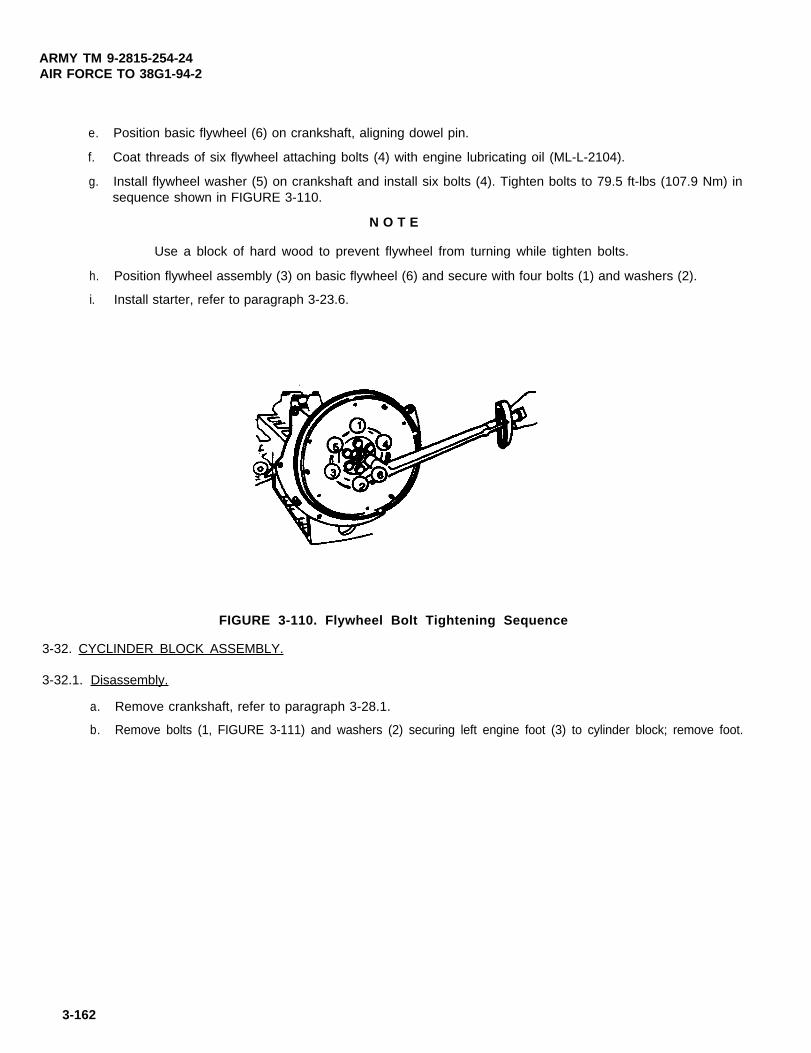
ARMY TM 9-2815-254-24AIR FORCE TO 38G1-94-2
e. Position basic flywheel (6) on crankshaft, aligning dowel pin.
f. Coat threads of six flywheel attaching bolts (4) with engine lubricating oil (ML-L-2104).
g. Install flywheel washer (5) on crankshaft and install six bolts (4). Tighten bolts to 79.5 ft-lbs (107.9 Nm) insequence shown in FIGURE 3-110.
N O T E
Use a block of hard wood to prevent flywheel from turning while tighten bolts.
h. Position flywheel assembly (3) on basic flywheel (6) and secure with four bolts (1) and washers (2).
i. Install starter, refer to paragraph 3-23.6.
FIGURE 3-110. Flywheel Bolt Tightening Sequence
3-32. CYCLINDER BLOCK ASSEMBLY.
3-32.1. Disassembly.
a. Remove crankshaft, refer to paragraph 3-28.1.
b. Remove bolts (1, FIGURE 3-111) and washers (2) securing left engine foot (3) to cylinder block; remove foot.
3-162

ARMY TM 9-2815-254-24AIR FORCE TO 38G1-94-2
c. Remove bolts (4) and washers (5) securing right engine foot (7) and alternator mounting bracket (6); removefoot and bracket.
d. Remove small freeze plug (8) on rear of engine and using a punch, drive coolant duct (9) from cylinder block.
e. Remove eight tappets (10) from block. If they are to be reused, tag them as to their location for use duringassembly.
N O T E
To remove rear camshaft bearing, remove freeze plug.
f. Remove camshaft bearings (11) using bearing remover/ installer (320905)
g. Remove two screws (12) securing cover (13) to engine block; remove cover (13) and packing (14). Discardpacking.
N O T E
If cylinder liner is removed, it must be replaced.
h. Remove cylinder liner (15) as follows:
(1) Insert cylinder liner remover (NU-7626) into cylinder block (from lower side) until it makes firm contactwith cylinder liner. Insert grip (7631) into cylinder liner remover.
Use care not to damage cylinder block upper face during cylinder linerremoval.
(2) Using an arbor press, slowly force cylinder liner from cylinder block.
i. Remove plugs, caps, and freeze plugs only if necessary.
3-163

ARMY TM 9-2815-254-24AIR FORCE TO 38G1-94-2
FIGURE 3-111. Cylinder Block Assembly
3-164 Change 2

ARMY TM 9-2815-254-24AIR FORCE TO 38G1-94-2
j. Remove dowel pins and fittings only if necessary.
3-32.2. lnspection/Repair.
NOTE
Letters and numbers are stamped on top face of block at each cylinderbore. Letters (A or C) represent grade of piston installed duringproduction. Numbers (1, 2, 3, or 4) represent grade of cylinder linerinstalled during production. However. when ordering a new cylinder linerfor service repair either a No. 2 or No. 3 grade cylinder liner will besupplied. Either one may be used to replace whatever grade liner wasused in production.
a. Check cylinder block upper face warpage as follows.
(1)
(2)
(3)
(4)
If not removed, remove dowel pin.
Remove cylinder liner, refer to paragraph 3-32.1 step h.
Using a straight edge and a feeler gage, measure the four sides and two diagonals of cylinderblock upper face, refer to FIGURE 3-112.
Standard warpage is 0.002 in. (0.05 mm) or less. If measured value exceeds 0.008 in. (0.2mm) but is less than 0.016 in. (0.4 mm), regrind the cylinder block. If measured value isgreater than 0.006 in. (0.14 mm), replace cylinder block.
Change 2 3-165

ARMY TM 9-2815-254-24AIR FORCE TO 38G1-94-2
(5)
FIGURE 3-112. Cylinder Block Upper Face Warpage Measurement
Standard cylinder block height is 10.748 in. (273 mm) with a limit of 10.732 in. (272.6 mm), refer to FIG-URE 3-113.
FIGURE 3-113. Cylinder Block Height Measurement
(6) Install cylinder liner, refer to paragraph 3-32.3.
(7) Install cylinder bled< dowel pin.
b. Measure cylinder liner bore as follows:
(1) Using a cylinder indicator, measure cylinder liner bore at a point 0.59 to 0.75 in. (15 to 19 mm) from topof liner where most wear is present. Take measurement in both the thrust and axial directions of the crank-shaft.
3-166

ARMY TM 9-2815-254-24AIR FORCE TO 38G1-94-2
(2) Standard cylinder liner bore is 3.386 in. (86.0 mm) with a limit of 3.394 in. (86.2 mm) If bore exceedslimit, replace cylinder liner.
N O T E
Inside of dry type cylinder liner is chrome plated and cannot be rebored.
N O T E
If inside of cylinder liner is scored or scorched, cylinder liner must bereplaced.
c. Check cylinder liner projection as follows:
(1) Hold a straight edge along top edge of cylinder liner to be checked.
(2) Using a feeler gage, measure each cylinder liner projection.
(3) Standard projection is 0.0 to 0.004 in. (0.0 to 0.10 mm).
(4) The difference in projection height between any two adjacent cylinders must not exceed 0.0012 in. (0.03mm).
d. Select piston grade as follows:
(1) The term grade refers to piston diameter and cylinder liner bore combination.
(2) Grade ‘A’ piston diameter is 3.3804 to 3.3812 in. (85.864 to 85.883 mm) and a Grade ‘C’ piston diameteris 3.3813 to 3.3820 in. (85.884 to 85.903 mm). These diameters are measured with a micrometer, 2.05in. (52 mm) from top of piston.
(3) Cylinder liner bore and piston clearance is 0.0057 to 0.0077 in. (0.146 to 0.196 mm).
3-167

ARMY TM 9-2815-254-24AIR FORCE TO 38G1-94-2
N O T E
Cylinder liner piston kit clearance are preset, Howerver, cylinder linerinstallation procedure may result in slight decrease in cylinder liner boreclearances. Always measure cylinder liner bore clearance after installa-tion to be sure that is correct.
e. Measure new cylinder liner bore as follows:
(1) Measure cylinder liner bore at two points, 'A' and 'B', in four different directions (W-W, X-X, Y-Y and Z-Z)as shown in FIGURE 3-114.
FIGURE 3-114. Cylinder Liner Bore Measurement
(2) Calculate average value of the eight measurememts. Standardbore is 3.387 to 3.388 in. (86.021 to 86.060mm).
(3) Select the appropriate piston grade as described in step d.
3-168
ARMY TM 9-2815-254-24AlR FORCE TO 38G1-94-2
N O T E
It is most important that correct piston grade be used. Failure to selectcorrect piston grade will result in engine failure. Always measure cylin-der bore and select correct piston grade.
3-32.3. Assembly.
Compressed air used for cleaning purposes will not exceed 30 psi (207kPa). Use only with effective chip guarding and personal protectiveequipment (goggles/shield, gloves, etc.).
a. Use compressed air to thoroughly clean cylinder block interior and exterior, oil holes, and water jackets beforeassembly.
b. Install dowel pins and fittings if removed.
c. Install new cylinder liners (15, FIGURE 3-111) as follows:
Diesel fuel is flammable and toxic to eyes, skin, and respiratory tract.Skin/eye protection required. Avoid repeated/prolonged contact. Goodgeneral ventilation is normally adequate.
(1) Use clean diesel fuel to thoroughly clean cylinder liners and bores.
(2) Blow dry with compressed air.
N O T E
All foreign material must be carefully removed from cylinder liner andbores before installation.
3-169

ARMY TM 9-2815-254-24AIR FORCE TO 38G1-94-2
(3) Insert cylinder liner into cylinder block from top, refer to FIGURE 3-115.
FIGURE 3-115. Cylinder Liner Installation
(4) Set cylinder liner installer (320903) on top of cylinder liner, refer to FIGURE 3-116.
(5) Position cylinder block so installer center is directly beneath arbor press shaft center.
N O T E
Check that cylinder liner is set perpendicular to arbor press and thatthere is no wobble.
(6) Using arbor press, apply a seating force of 1102.5 lbs (500 kg) to cylinder liner.
(7) Apply a force of 5512.5 Ibs (2500 kg) to fully seated cylinder liner.
(8) Measure cylinder liner projection, refer to paragraph 3-32.2, step c.
3-170
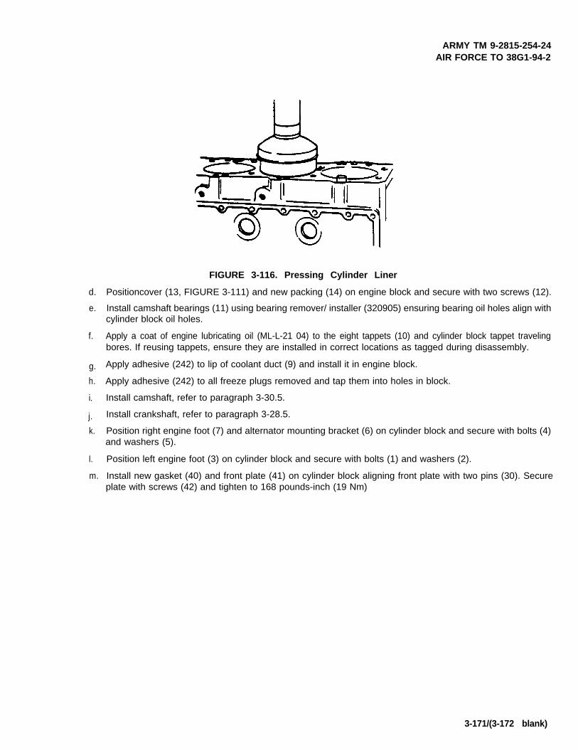
ARMY TM 9-2815-254-24AIR FORCE TO 38G1-94-2
d.
e.
f.
g.
h.
i.
j.
k.
I.
m.
FIGURE 3-116. Pressing Cylinder Liner
Positioncover (13, FIGURE 3-111) and new packing (14) on engine block and secure with two screws (12).
Install camshaft bearings (11) using bearing remover/ installer (320905) ensuring bearing oil holes align withcylinder block oil holes.
Apply a coat of engine lubricating oil (ML-L-21 04) to the eight tappets (10) and cylinder block tappet travelingbores. If reusing tappets, ensure they are installed in correct locations as tagged during disassembly.
Apply adhesive (242) to lip of coolant duct (9) and install it in engine block.
Apply adhesive (242) to all freeze plugs removed and tap them into holes in block.
Install camshaft, refer to paragraph 3-30.5.
Install crankshaft, refer to paragraph 3-28.5.
Position right engine foot (7) and alternator mounting bracket (6) on cylinder block and secure with bolts (4)and washers (5).
Position left engine foot (3) on cylinder block and secure with bolts (1) and washers (2).
Install new gasket (40) and front plate (41) on cylinder block aligning front plate with two pins (30). Secureplate with screws (42) and tighten to 168 pounds-inch (19 Nm)
3-171/(3-172 blank)


ARMY TM 9-2815-254-24AIR FORCE TO 38G1-94-2
APPENDIX AREFERENCES
A-1 SCOPE.
This appendix lists all forms, field manuals, technical manuals and miscellaneous publications referenced in this manual
A-2 FORMS.
Air Force Reporting of Errors Form . . . . . . . . . . . . . . . . . . . . . . . . . . . . . . . . . . . . . . . . . . . . . . . . . . . . . . . AFTO Form 22
Product Quality Deficiency Report . . . . . . . . . . . . . . . . . . . . . . . . . . . . . . . . . . . . . . . . . . . . . . . . . . . . . . . . . . . . . . . SF 368
Recommended Changes to DA Publications . . . . . . . . . . . . . . . . . . . . . . . . . . . . . . . . . . . . . . . . . . . . . . DA Form 2028-2
Recommended Changes to Publications and Blank Forms . . . . . . . . . . . . . . . . . . . . . . . . . . . . . . . . . . DA Form 2028
Report of Discrepancy (ROD) . . . . . . . . . . . . . . . . . . . . . . . . . . . . . . . . . . . . . . . . . . . . . . . . . . . . . . . . . . . . . . . . . . . SF 384
Reporting of Item and Packaging Discrepancies . . . . . . . . . . . . . . . . . . . . . . . . . . . . . . . . . . . . . . . . . . . . . . AR 735-11-2
Reporting of Transportation Discrepancies in Shipment . . . . . . . . . . . . . . . . . . . . . . . . . . . . . . . . . . . . . . . . . . AR 55-38
Transportation Discrepancy Report . . . . . . . . . . . . . . . . . . . . . . . . . . . . . . . . . . . . . . . . . . . . . . . . . . . . . . . . . . . SF 361
Equipment Control Records . . . . . . . . . . . . . . . . . . . . . . . . . . . . . . . . . . . . . . . . . . . . . . . . . . . . . . . . . . DA Form 2408-9
A-3 FIELD MANUALS.
First Aid for Soldiers . . . . . . . . . . . . . . . . . . . . . . . . . . . . . . . . . . . . . . . . . . . . . . . . . . . . . . . . . . . . . . . . . . . . . . . . . FM 21-11
A-4 TECHNICAL MANUALS.
Destruction of Materiel . . . . . . . . . . . . . . . . . . . . . . . . . . . . . . . . . . . . . . . . . . . . . . . . . . . . . . . . . . . . . . . . . . . TM 750-244-3
A-5 MISCELLANEOUS PUBLICATIONS.
Maintenance Management Policy . . . . . . . . . . . . . . . . . . . . . . . . . . . . . . . . . . . . . . . . . . . . . . . . . . . . . . . . . . . . . AFR 88-1
Preservation of USAMECOM MechanicalEquipment for Shipment and Storage . . . . . . . . . . . . . . . . . . . . . . . . . . . . . . . . . . . . . . . . . . . . . . . . . . . TB 740-97-2
A-1

ARMY TM 9-2815-254-24AIR FORCE TO 38G1-94-2
APPENDIX AREFERENCES - CONTINUED
A-5 MlSCELLANEOUS PUBLICATIONS - Continued
Suggestion Program . . . . . . . . . . . . . . . . . . . . . . . . . . . . . . . . . . . . . . . . . . . . . . . . . . . . . . . . . . . . . . . . . . . . . . . . AFR 900-4
The Army Maintenance Management System (TAMMS) . . . . . . . . . . . . . . . . . . . . . . . . . . . . . . . . . . . DA PAM 738-750
USAF Materiel Deficiency Reporting . . . . . . . . . . . . . . . . . . . . . . . . . . . . . . . . . . . . . . . . . . . . . . . . . . . . . . TO-OO-35D54
A-2

ARMY TM 9-2815-254-24AIR FORCE TO 38G1-94-2
APPENDIX BMAINTENANCE ALLOCATlON CHART
SECTlON I.INTRODUCTION
B-1 General.
a. This section provides a general explanation of all maintenance and repair functions authorized at various main-tenance categories.
b. The Maintenance Allocation Chart (MAC) in section II designates overall authority and responsibility for theperformance of maintenance functions on the diesel engine and its components. The application of the mainte-nance functions to the engine or components will be consistent with the capacities and capabilities of the desig-nated maintenance categories.
c. Section III lists the tools and test equipment (both special tools and common tool sets) required for each mainte-nance function as referenced from section II.
d. Section IV contains supplemental instructions and explanatory notes for particular maintenance functions.
B-2 Maintenance Functions. Maintenance functions will be limited to and defined as follows:
a.
b.
c.
d.
e.
Inspect. To determine the serviceability of an item by comparing its physical, mechanical, and/or electrical char-acteristics with established standards through examination (e.g., by sight, sound, or feel).
Test. To verify serviceability by measuring the mechanical, pneumatic, or electrical characteristics of an itemand comparing those characteristics with prescribed standards.
Service. Operations required periodically to keep an item in proper operating condition, i.e., to clean (includedecontaminate, when required), to preserve, to drain, to paint, or to replenish fuel, lubricants, chemical fluids,or gases.
Adjust. To maintain or regulate, within prescribed limits, by bringing into proper or exact position, or by settingthe operating characteristics to specified parameters.
Aline. To adjust specified variable elements of an item to bring about optimum or desired performance.
B-1

ARMY TM 9-2815-254-24AIR FORCE TO 38G1-94-2
f.
g.
h.
i.
j.
k.
Calibrate. To determine and cause corrections to be made or to be adjusted on instruments or Test, Measuring,and Diagnostic Equipment (TMDE) used in precision measurement. Consists of comparisons of two instru-ments, one of which is a certified standardof known accuracy, to detect and adjust any discrepancy in the accu-racy of the instrument being compared.
Remove/Install. To remove and install the same item when required to perform service or other maintenancefunctions. Install may be the act of emplacing, seating, or fixing into position a spare, repair part, or module(component or assembly) in a manner to allow the proper functioning of an equipment or system.
Replace. To remove an unserviceable item and install a serviceable counterpart in its place. Replace is autho-rized by the MAC and is shown as the 3rd position code of the SMR code.
Repair. The application of maintenance services, including fault location/troubleshooting, removal/installationand disassembly/assembly procedures, and maintenance actions to identify troubles and restore serviceabilityto an item by correcting specific damage, fault, malfunction, or failure in a part, subassembly, module (compo-nent or assembly), end item, or system.
Overhaul. That maintenance effort (service/action) prescribed to restore an item to a completely serviceable/operational condition as required by maintenance standards in appropriate technical publications (i.e.,DMWR). Overhaul is normally the highest degree of maintenance performed by the Army. Overhaul does notnormally return an item to like new condition.
Rebuild. Consists of those services/actions necessary for the restoration of unserviceable equipment to a likenew condition in accordance with original manufacturing standards. Rebuild is the highest degree of materialmaintenance applied to Army equipment. The rebuild operation includes the act of returning to zero those agemeasurements (hours/miles, etc.) considered in classifying Army equipment/components.
B-3 Explanation of Columns in the MAC, Section II
a. Column 1, Group Number. Column 1 lists functional group code numbers, the purpose of which are to identifymaintenance significant components, assemblies, subassemblies, and modules with the next higher assem-bly. End item group number shall be “00”.
b. Column 2, Component/Assembly. Column 2 contains the names of components, assemblies, subassemblies,and modules for which maintenance is authorized.
B-2

ARMY TM 9-2815-254-24AIR FORCE TO 38G1-94-2
c. Column 3, Maintenance Function. Column 3 lists the function to be performed on the item listed in column 2.(For detailed explanation of these functions, see paragraph B-2).
d. Column 4, Maintenance Category. Column 4 specifies, by the listing of a work time figure in the appropriates&column(s), the category of maintenance authorized to perform the function listed in column 3. This figurerepresents the active time required to perform that maintenance function at the indicated category of mainte-nance. If the number or complexity of the tasks within the listed maintenance function vary at different mainte-nance categories, appropriate work time figures will be shown for each category. The work time figure repre-sents the average time required to restore an item (assembly, subassembly, component, module, end item,or system) to a serviceable condition under typical field operating conditions. This time includes preparationtime (including any necessary disassembly/assembly time), troubleshooting/fault location time, and quality as-surance/quality control time in addition to the time required to perform the specific tasks identified for the main-tenance functions authorized in the Maintenance Allocation Chart. The symbol designations for the variousmaintenance categories are as follows:
C . . . . . . . . . . . . . . . . . Operator or crewO . . . . . . . . . . . . . . . . . Organization MaintenanceF . . . . . . . . . . . . . . . . . Direct Support MaintenanceH General Support MaintenanceD Depot Maintenance
e. Column 5, Tools and Equipment. Column 5 specifies, by code, those common tool sets (not individual tools)and special tools, TMDE, and support equipment required to perform the designated function.
f. Column 6, Remarks. This column shall, when applicable, contain a letter code, in alphabetical order, which shallbe keyed to the remarks contained in Section IV.
B-4 Explanation of Columns in Tool and Test Equipment Requirements, Section III
a. Column 1, Reference Code. The tool and test equipment reference code correlates with a code used in theMAC, Section II, Column 5.
b. Column 2, Maintenance Category. The lowest category of maintenance authorized to use the tool or test equip-ment.
c. Column 3, Nomenclature. Name or identification of the tool or test equipment.
B-3

ARMY TM 9-2815-254-24AIR FORCE TO 38G1-34-2
d. Column 4, National Stock Number. The National Stock Number of the tool or test equipment.
e. Column 5, Tool Number. The manufacturer's part number of the tool or test equipment.
B-5 Explanation of Columns in Remarks, Section IV
a. Column 1, Reference Code. The code recorded in column 6, II.
b. Column 2, Remarks. This lists information pretinent to the maintenance function being performed asindicated in the MAC, Section II.
B-4

ARMY TM 9-2815-254-24AIR FORCE TO 38G1-34-2
Change B-5
SECTlON II. MAINTENANCE ALLOCATION CHARTFOR
DIESEL ENGINE MODEL C-240PW-28
(1) ( 2 ) (3) ( 4 ) ( 5 )GROUP COMPONENT/ASSEMBLY MAINTENANCE MAlNTENANCE CATEGORY TOOLS
(6)REMARKS
NUMBER FUNCTION ANDC O F H D EQUIP.
00 ENGINE ASSEMBLY 15KW INSPECTSERVICETESTADJUSTREPAIRR/IREPLACEOVERHAULINSPECT
0100 COOLING SYSTEM SERVICEREPAIR
0101 THERMOSTAT lNSPECTREPLACE
0102 WATER PUMP INSPECTR/IREPLACE
0200 FUEL SYSTEM INSPECTSERVICEREPAIR
0201 FUEL FILTER INSPECT
0202 FUEL INJECTOR INSPECTADJUSTTESTR / IREPLACEREPAIR
0203 FUEL INJECTION PUMP lNSPECTTEST
REPLACER/I
REPAIR
0300 LUBRICATION SYSTEM INSPECTSERVICER E P A I RINSPECT
0301 OIL FILTER REPLACE0302 OIL PRESSURE RELIEF INSPECT
VALVE TESTR/IREPLACE
0303 OIL PANINSPECTREPLACE
0304 OlL PUMP ASSEMBLY INSPECTR / IREPLACEREPAIR
0400 INTAKE/EXHAUST SYSTEM INSPECTREPAIR

ARMY TM 9-2815-254-24AIR FORCE TO 38G1-94-2
0401
0402
0403
0500
0501
0502
0503
0601
060101
0602
0603
0604
SECTION II. MAlNTENANCE ALLOCATIONCHART - ContinuedFOR
DIESEL ENGINE MODEL C-240PW-28
PCV ASSEMBLY
INTAKE MANIFOLD
EXHAUST MANIFOLD
ELECTRICAL SYSTEM
GLOW PLUGS
STARTER MOTOR ASSY
ALTERNATOR ASSEMBLY
ENGINE BLOCK ASSEMBLY INSPECT
FRONT GEAR COVER
SEAL, CRANKSHAFTWONTROCKER ARM ASSEMBLY
CYLINDER HEAD ASSY
VALVE SPRINGS
INSPECTSERVICE
REPLACER/I
REPAIR
INSPECTR/IREPLACEINSPECT
REPLACER/I
INSPECTREPAIRINSPECTTESTR/lREPLACEINSPECTTESTR/lREPLACEREPAIRINSPECTTESTR/IREPLACEREPAIR
ADJUSTTESTREPAIRINSPECTR/lREPLACEREPAIRINSPECTREPLACEINSPECTADJUSTTEST
REPLACER/I
REPAIR
INSPECTTEST
REPLACER/I
REPAIRINSPECTTESTR/IREPLACE
B-6 Change

ARMY TM 42815-254-24AIR FORCE TO 38G1-94-2
SECTION I I . MAINTENANCE ALLOCATION CHART - Cont inued
F O RDIESEL ENGINE MODEL C-240PW-28
(1) (2)GROUP COMPONENT/ASSEMBLY MAINTENANCE
(4)MAINTENANCE CATEGORY TOOLS
(6)REMARKS
NUMBER FUNCTIONC O F H D EQUIP.
0605 INTAKE/EXHAUST VALVES INSPECTTEST .5 3R/I 5.0 3,5REPLACE 5.0 3.5 CREPAIR 6:0 3
0606 CONNECTING ROD & INSPECT .5PISTON ASSEMBLY TEST 1.0 3,4.5
R/I 8.0REPLACE 8.0REPAIR 9.0
1,3,5 C1,4,5
0607 IDLER GEAR ASSEMBLY INSPECT .2TEST 1.0R/I 3.5
3,5
REPLACE1.5
3.5 1,5 CREPAIR 4.5 1.5
0606 CAMSHAFT ASSEMBLY INSPECT .5TEST 1.0 3,5R/I 4.0 5REPLACE 4.0
5.05 C
REPAIR 1,4,50609 FLYWHEEL ASSEMBLY INSPECT .2
R/I 1.0REPLACE 1.0 1,5 CREPAIR 2.0 1.5
0610 SEAL, CRANKSHAFT INSPECT .1REAR REPLACE 1.0 5, 12
0611 CRANKSHAFT ASSEMBLY INSPECT .5TEST 1.0 3R/I 10.0 1,5REPLACE 10.0 1,5 CREPAIR 11.0 3,4, 5, 10
0612 MAIN & ROD BEARINGS INSPECTTEST 1.5 3
11.5 1.5REPLACE 11.5 1,5 C
0613 CRANKCASE ASSEMBLY INSPECT .5TEST 1.0 3,4,5
12.0REPLACE 12.0 1,5 CREPAIR 14.0
061301 CYLINDER LINERS INSPECT 2TEST 1.0REPLACE 2.0 5,11,14,15
061302 CAMSHAFT BEARINGS INSPECT .2TEST 1.0 3REPLACE 2.0 5, 13
B-7

ARMY TM 9-2815-254-24AIR FORCE TO 38G1-94-2
TOOL OR TESTEQUIPMENT REF
CODE1 O, F, H
2
3
4 F,H
5 O, F, H TOOL KIT, GENERAL MECHANICS 5160-00-177-7033
6 F TESTER, PRESSURE GAGE7 F ADAPTER, COMPRESSION GAGE6 F, H TEST SET, FUEL INJECTlON PUMP9 H PLUNGER, SPRING HOLDER
10 H INSTALLER, CRANKSHAFT GEAR11 H GRIP12 F INSTALLER, CRANKSHAFT REAR OIL SEAL13 H REMOVER/INSTALLER, CAMSHAFT BEARING14 H INSTALLER. CYLINDER LINER15 H REMOVER,CYLlNDERLlNER16 H INSTALLER, OIL SEAL17 F REPLACER, VALVE GUIDE16 H SPANNER19 H EXTRACTOR20 H BRACKET21 H UNIVERSAL VISE22 H COUPUNG23 H SPANNER24 H TAPPET INSTALLER25 H CLAMP26 H EXTRACTOR27 H INSERTER TOOL26 H MEASURING DEVICE29 H MEASURING DEVlCE
SECTlON Il l . TOOL AND TEST EQUIPMENT REQUIREMENTSF O R
DIESEL ENGINE MODEL C-240PW-28
MAINTENANCECATEGORY
F
H
NOMENCLATURE
SHOP EQUIPMENT. AUTOMOTIVE MAINTE-NANCE AND REPAIR: ORGANlZATlONAL MAlN-TENANCE COMMON NO. 1, LESS POWERSHOP EQUIPMENT. FUEL AND ELECTRICALSYSTEM ENGINE. FIELD MAlNTENANCE BASIC,LESS POWERSHOP EQUIPMENT, AUTOMOTIVE MAINTE-NANCE AND REPAIR: FIELD MAINTENANCE,SUPPLEMENTAL SET NO. 2, LESS POWERTOOL SET, BASIC, FIELD MAINTENANCE
NATIONAL/STOCKNUMBER
4910-00-754-0654
4940-00-754-0714
4910-00-754-0707
4910-00-754-0705
6685-00-263-06584910-01-196-86704910-01-121-6869
- - -5120-01-263-87525340-01-265-67345120-01-268-88265120-01-263-87515120-01-263-87495120-01-263-87505120-01-268-88225120-01-266-6823
- - -- - -- - -- - -- - -- - -
5120-01-056-1997- - -- - -- - -- - -- - -
TOOL NUMBER
SC4910-95CL-A74
SC4910-95CL-820
SC4910-95CL-A63
SC4910-95-CLA31SC5180-90-CL-N26MIL-T-2764J-26999-277-7028157931-41003209067631NU7627320905320903NU-76285-8522-0013-0NW7634157916-5320157926-6220157944-7620157944-6520157842-4420!57916-5420157921-0120157931-6120157920-9620157924-1620105782-6280106782-4020
B-8

ARMY TM 9-2815-254-24AIR FORCE TO 38G1-94-2
SECTlON IV. REMARKSF O R
DIESEL ENGINE MODEL C-240PW-28
REFERENCECODE
REMARKS
A Refer to end item operator’s manual.
B Refer to end item maintenance manual.
C Replace function is identical to removal/install function.
D Fuel filter does not include a filter element for this application. Refer to end item maintenancemanual for fuel filter requirement.
E Repair limited to replacement of gear.
B-9/(B-10 blank)

ARMY TM 9-2815-254-24AIR FORCE TO 38G1-94-2
APPENDIX CEXPENDABLE/DURABLE SUPPLIES AND MATERIALS LIST
SECTION I. INTRODUCTION
C-1 SCOPE.
This appendix lists expendable supplies and materials you will need to operate and maintain the engine: These items areauthorized to you by CTA 50-970, Expendable Items (except Medical, Class V, Repair Parts, and Heraldic Items).
C-2 EXPLANATION OF COLUMNS.
a.
b.
c.
d.
e.
Column (1) - Item Number. This number is assigned to each entry in the listing.
Column (2) - Level. This column identifies the lowest level of maintenance that requires the listed item.
Column (3) - National Stock Number. This is the National Stock Number assigned to the item; use it to requestor requisition the item.
Column (4) - Description. Indicates the Federal item name and, if required, a description to identify the item.The last line for each item indicates the Commercial and Government Entity (CAGE) code in parentheses( ) followed by the part number.
Column (5) - Unit of Measure (U/M). lndicates the measure used in performing the actual maintenance function.
This measure is expressed by a two-character alphabetical abbreviation (e.g., ea, in, pr). If the unit of mea-sures differs from the unit of issue, requisition the lowest unit of issue that will satisfy your requirements.
C-1

ARMY TM 9-2615-25624AIR FORCE TO 38G1-94-2
APPENDIX C
EXPENDABLE/DURABLE SUPPLIES AND MATERIALS LIST - CONTINUED
NATIONAL
DESCRIPTION U/M
Compound, Lapping,SSL1682
Gage, Bearing Clear,PLASTlGAGEPR1
Paper, Abrasive, #400
9150-00-152-4117DS/GS
10 Unit/ 5350-00-224-7201DSGS
11 Unit./ 8030-00-849-0071DS/GS
12 DS/GS 3439-00-974-1873
13 Unit/ 6850-00-264-9038DS/GS
(1) (2) (3)
ITEM STOCKNUMBER LEVEL NUMBER
1 DS/GS 8040-01-250-3969
2 DS/GS 8040-00-390-7959
3 DS/GS 8040-01-055-6407 Adhesive, Silicon
584R46001101
4 DS/GS 6850-00-311-6172 Bearing Dye, Blue,
HISPOTBLUE 107
5 Units/ 7920-01-338-3329DS/GS
6 DS/GS 5350-00-009-1751
7 DS/GS 5210-00-640-6178
8 DS/GS 9150-00-053-0101 Grease Molybdenum Disulfide
MOLYKOTEZ
9 Unit/ lubricating Oil, Eng 15/40W,MIL-L-2104
Cloth, Cleaning, TX- 1250 EA
SHT
T U
OZ
BX
Sealing Compound,FORMAGASKET2
Solder, Tn Alloy,SN60WRAP2,1 lb Spool
Solvent, Dry Cleaning, P-D-680,5Gal. Can
GL
OZ
Adhesive, LOCTITE 242 Tu
Adhesive, Seal, 847 Tu
(4) (5)
TU
EA
TU
QT
C-2

ARMY TM 9-2815-254-24AIR FORCE TO 38G1-94-2
APPENDIX D
FABRICATION OF TOOLS
FIGURE D-1. Fuel Injection Pump Tappet Holder
D-1/(D-2 blank)


ARMY TM 9-2815-254-24AIR FORCE TO 38G1-94-2
Appendix E. MAINTENANCE PROCEDUREAND AUTHORIZED LEVEL OF MAINTENANCE
Section I. INTRODUCTlON
SCOPE. This appendix shall be used when a Commercial Off The Shelf (COTS) manual is used by theMilitary services. This appendix is divided into three sections. Section I gives a brief description of thesections within this appendix. Section II list the paragraphs to the associated maintenance level. SectionIII list the maintenance level to the associated paragraphs.
Change 1 E-1

ARMY TM 9-2815-254-24AIR FORCE TO 38G1-94-2
Section 111. MAINTENANCE LEVELTD PARAGRAPHS

ARMY TM 9-2815-254-24AIR FORCE TO 38G1-94-2
I N D E X
Description Page No.
A
Adjustment, Valve Clearance . . . . . . . . . . . . . . . . . . . . . . . . . . . . . . . . . . . . . . . . . . . . . . . . . . . . . . . . . . . . . . . . . . . . 3-109Alternator, Maintenance of . . . . . . . . . . . . . . . . . . . . . . . . . . . . . . . . . . . . . . . . . . . . . . . . . . . . . . . . . . . . . . . . . . . . . . . . 3 - 9 3
B
Bleeding And Priming Fuel System . . . . . . . . . . . . . . . . . . . . . . . . . . . . . . . . . . . . . . . . . . . . . . . . . . . . . . . . . . . . . . . . . 3-65
C
Camshaft And Idler Gear Assemblies, Maintenance of . . . . . . . . . . . . . . . . . . . . . . . . . . . . . . . . . . . . . . . . . . . . . . 3-150Compression Check . . . . . . . . . . . . . . . . . . . . . . . . . . . . . . . . . . . . . . . . . . . . . . . . . . . . . . . . . . . . . . . . . . . . . . . . . . . . 3-127Crankcase Fastener Tightening Sequence . . . . . . . . . . . . . . . . . . . . . . . . . . . . . . . . . . . . . . . . . . . . . . . . . . . . . . . . . 3-150Crankcase, Maintenance of . . . . . . . . . . . . . . . . . . . . . . . . . . . . . . . . . . . . . . . . . . . . . . . . . . . . . . . . . . . . . . . . . . . . . . 3-148Crankshaft Bearing Cap Bolt Loosening Sequence . . . . . . . . . . . . . . . . . . . . . . . . . . . . . . . . . . . . . . . . . . . . . . . . . 3-130Crankshaft Bearing Cap Bolts Tightening Sequence . . . . . . . . . . . . . . . . . . . . . . . . . . . . . . . . . . . . . . . . . . . . . . . . 3-145Cylinder Block Assembly, Maintenance of . . . . . . . . . . . . . . . . . . . . . . . . . . . . . . . . . . . . . . . . . . . . . . . . . . . . . . . . . 3-162Cylinder Head Assembly, Maintenance of . . . . . . . . . . . . . . . . . . . . . . . . . . . . . . . . . . . . . . . . . . . . . . . . . . . . . . . . . 3-110Cylinder Head Bolt Loosening Sequence . . . . . . . . . . . . . . . . . . . . . . . . . . . . . . . . . . . . . . . . . . . . . . . . . . . . . . . . . . 3-112Cylinder Head Bolt Tightening Sequence . . . . . . . . . . . . . . . . . . . . . . . . . . . . . . . . . . . . . . . . . . . . . . . . . . . . . . . . . . 3-126
D
DetailedDescription . . . . . . . . . . . . . . . . . . . . . . . . . . . . . . . . . . . . . . . . . . . . . . . . . . . . . . . . . . . . . . . . . . . . . . . . . . . . ...1-3
E
Electrical System, Maintenance of . . . . . . . . . . . . . . . . . . . . . . . . . . . . . . . . . . . . . . . . . . . . . . . . . . . . . . . . . . . . . . . . . 3 - 8 5Engine Block Maintenance . . . . . . . . . . . . . . . . . . . . . . . . . . . . . . . . . . . . . . . . . . . . . . . . . . . . . . . . . . . . . . . . . . . . . . . 3 - 9 9Equipment Data. . . . . . . . . . . . . . . . . . . . . . . . . . . . . . . . . . . . . . . . . . . . . . . . . . . . . . . . . . . . . . . . . . . . . . . . . . . . . . . . . . .1- 5
F
Flywheel And Housing, Maintenance of . . . . . . . . . . . . . . . . . . . . . . . . . . . . . . . . . . . . . . . . . . . . . . . . . . . . . . . . . . . 3-158Flywheel Bolt Loosening Sequence . . . . . . . . . . . . . . . . . . . . . . . . . . . . . . . . . . . . . . . . . . . . . . . . . . . . . . . . . . . . . . . 3-160Flywheel Bolt Tightening Sequence . . . . . . . . . . . . . . . . . . . . . . . . . . . . . . . . . . . . . . . . . . . . . . . . . . . . . . . . . . . . . . . 3-162Flywheel Housing Installation Sequence . . . . . . . . . . . . . . . . . . . . . . . . . . . . . . . . . . . . . . . . . . . . . . . . . . . . . . . . . . 3-161Front Gear Cover Screw Tightening Sequence . . . . . . . . . . . . . . . . . . . . . . . . . . . . . . . . . . . . . . . . . . . . . . . . . . . . . 3-101Front Gear Cover, Maintenance of . . . . . . . . . . . . . . . . . . . . . . . . . . . . . . . . . . . . . . . . . . . . . . . . . . . . . . . . . . . . . . . . . .3-99Fuel Filter Assembly, Maintenance of . . . . . . . . . . . . . . . . . . . . . . . . . . . . . . . . . . . . . . . . . . . . . . . . . . . . . . . . . . . . . . 3-21Fuel Injection Pump Timing . . . . . . . . . . . . . . . . . . . . . . . . . . . . . . . . . . . . . . . . . . . . . . . . . . . . . . . . . . . . . . . . . . . . . . . 3 - 6 5
Fuel Injection Pump, Maintenance of . . . . . . . . . . . . . . . . . . . . . . . . . . . . . . . . . . . . . . . . . . . . . . . . . . . . . . . . . . . . . . 3-31Fuel Injectors And Piping, Maintenance of . . . . . . . . . . . . . . . . . . . . . . . . . . . . . . . . . . . . . . . . . . . . . . . . . . . . . . . . . . 3 - 2 4Fuel System Maintenance . . . . . . . . . . . . . . . . . . . . . . . . . . . . . . . . . . . . . . . . . . . . . . . . . . . . . . . . . . . . . . . . . . . . . . . . 3-21
Index 1

ARMY TM 9-2815-254-24AIR FORCE TO 38G1-94-2
INDEX-Continued
Description Page No.
G
Glow Plug, Maintenance of . . . . . . . . . . . . . . . . . . . . . . . . . . . . . . . . . . . . . . . . . . . . . . . . . . . . . . . . . . . . . . . . . . . . . . . . . .3-85
I
Inspecting And Servicing Engine . . . . . . . . . . . . . . . . . . . . . . . . . . . . . . . . . . . . . . . . . . . . . . . . . . . . . . . . . . . . . . . . . . 1-6lntake And Exhaust Manifolds, Maintenance of.. . . . . . . . . . . . . . . . . . . . . . . . . . . . . . . . . . . . . . . . . . . . . . . . . . . . . 3-92
Intake And Exhaust System, Maintenance of . . . . . . . . . . . . . . . . . . . . . . . . . . . . . . . . . . . . . . . . . . . . . . . . . . . . . . . . 3-79
lntroduction. . . . . . . . . . . . . . . . . . . . . . . . . . . . . . . . . . . . . . . . . . . . . . . . . . . . . . . . . . . . . . . . . . . . . . . . . . . . . .. . . . . . . . . ... 1-1
L
Leading Particulars . . . . . . . . . . . . . . . . . . . . . . . . . . . . . . . . . . . . . . . . . . . . . . . . . . . . . . . . . . . . . . . . . . . . . . . . . . . . . . . . 1-5List of Illustrations . . . . . . . . . . . . . . . . . . . . . . . . . . . . . . . . . . . . . . . . . . . . . . . . . . . . . . . . . . . . . . . . . . . . . . . . . . . . . . . . . . i vList of Tables . . . . . . . . . . . . . . . . . . . . . . . . . . . . . . . . . . . . . . . . . . . . . . . . . . . . . . . . . . . . . . . . . . . . . . . . . . . . . . . . . . . . viiLubrication System, Maintenance of . . . . . . . . . . . . . . . . . . . . . . . . . . . . . . . . . . . . . . . . . . . . . . . . . . . . . . . . . . . . . . . . 3-89
O
Oil Fitter, Maintenance of . . . . . . . . . . . . . . . . . . . . . . . . . . . . . . . . . . . . . . . . . . . . . . . . . . . . . . . . . . . . . . . . . . . . . . . . . . 3-69Oil Pan ,Maintenance of. . . . . . . . . . . . . . . . . . . . . . . . . . . . . . . . . . . . . . . . . . . . . . . . . . . . . . . . . . . . . . . . . . . . . . . . . . . 3-73Oil Piping, Maintenance of.. . . . . . . . . . . . . . . . . . . . . . . . . . . . . . . . . . . . . . . . . . . . . . . . . . . . . . . . . . . . . . . . . . . . . . . 3-71Oil Pump, Maintenance of . . . . . . . . . . . . . . . . . . . . . . . . . . . . . . . . . . . . . . . . . . . . . . . . . . . . . . . . . . . . . . . . . . . . . . . 3-75
P
PCV Assembly, Maintenance of . . . . . . . . . . . . . . . . . . . . . . . . . . . . . . . . . . . . . . . . . . . . . . . . . . . . . . . . . . . . . . . . . . . 3-79Pistons, Connecting Rods, and Crankshaft, Maintenance of . . . . . . . . . . . . . . . . . . . . . . . . . . . . . . . . . . . . . . . . . 3-127PMCS Proceduras . . . . . . . . . . . . . . . . . . . . . . . . . . . . . . . . . . . . . . . . . . . . . . . . . . . . . . . . . . . . . . . . . . . . . . . . . . . . . . . . . 3-1Preparation For Use . . . . . . . . . . . . . . . . . . . . . . . . . . . . . . . . . . . . . . . . . . . . . . . . . . . . . . . . . . . . . . . . . . . . . . . . . . . . . 1-6Preventive Maintenance Checks And Services . . . . . . . . . . . . . . . . . . . . . . . . . . . . . . . . . . . . . . . . . . . . . . . . . . . . . . . . 3-1Principlesof Operation.. . . . . . . . . . . . . . . . . . . . . . . . . . . . . . . . . . . . . . . . . . . . . . . . . . . . . . . . . . . . . . . . . . . . . . . . . . 2-1
R
Rocker Arm Retaining Plate Bolt Loosening Sequence . . . . . . . . . . . . . . . . . . . . . . . . . . . . . . . . . . . . . . . . . . . . . . 3-104Rocker Arm Retaining Plate Bolt Tightening Sequence . . . . . . . . . . . . . . . . . . . . . . . . . . . . . . . . . . . . . . . . . . . . . . 3-109Rocker Cover And Arms, Maintenance of . . . . . . . . . . . . . . . . . . . . . . . . . . . . . . . . . . . . . . . . . . . . . . . . . . . . . . . . . . 3-102
S
Safety Summary . . . . . . . . . . . . . . . . . . . . . . . . . . . . . . . . . . . . . . . . . . . . . . . . . . . . . . . . . . . . . . . . . . . . . . . . . . . . . . . . . . . aScope . . . . . . . . . . . . . . . . . . . . . . . . . . . . . . . . . . . . . . . . . . . . . . . . . . . . . . . . . . . . . . . . . . . . . . . . . . . . . . . . . . . . . . . . . . . 1-1Starter Assembly, Maintenance of . . . . . . . . . . . . . . . . . . . . . . . . . . . . . . . . . . . . . . . . . . . . . . . . . . . . . . . . . . . . . . . . 3-85Symptom Index . . . . . . . . . . . . . . . . . . . . . . . . . . . . . . . . . . . . . . . . . . . . . . . . . . . . . . . . . . . . . . . . . . . . . . . . . . . . . . . . . . . . 3-3
Index 2
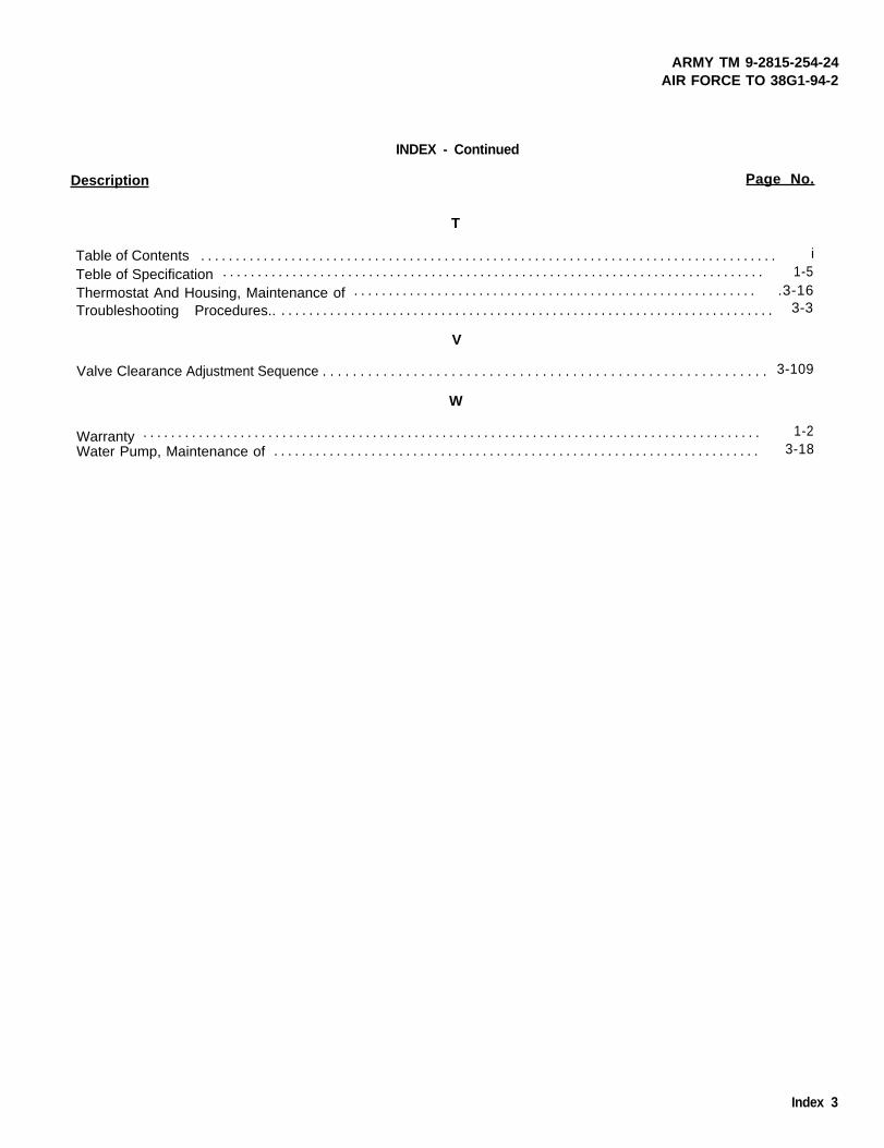
ARMY TM 9-2815-254-24AIR FORCE TO 38G1-94-2
INDEX - Continued
Description Page No.
T
Table of Contents . . . . . . . . . . . . . . . . . . . . . . . . . . . . . . . . . . . . . . . . . . . . . . . . . . . . . . . . . . . . . . . . . . . . . . . . . . . . . . . . . . . i
Teble of Specification . . . . . . . . . . . . . . . . . . . . . . . . . . . . . . . . . . . . . . . . . . . . . . . . . . . . . . . . . . . . . . . . . . . . . . . . . . . . . . 1-5
Thermostat And Housing, Maintenance of . . . . . . . . . . . . . . . . . . . . . . . . . . . . . . . . . . . . . . . . . . . . . . . . . . . . . . . . . . .3-16Troubleshooting Procedures.. . . . . . . . . . . . . . . . . . . . . . . . . . . . . . . . . . . . . . . . . . . . . . . . . . . . . . . . . . . . . . . . . . . . . . . . 3-3
V
Valve Clearance Adjustment Sequence . . . . . . . . . . . . . . . . . . . . . . . . . . . . . . . . . . . . . . . . . . . . . . . . . . . . . . . . . . . 3-109
W
Warranty . . . . . . . . . . . . . . . . . . . . . . . . . . . . . . . . . . . . . . . . . . . . . . . . . . . . . . . . . . . . . . . . . . . . . . . . . . . . . . . . . . . . . . . . . 1-2Water Pump, Maintenance of . . . . . . . . . . . . . . . . . . . . . . . . . . . . . . . . . . . . . . . . . . . . . . . . . . . . . . . . . . . . . . . . . . . . . . 3-18
Index 3


These are the instructions for sending an electronic 2028
The following format must be used if submitting an electronic 2028. The subject line must be exactly thesame and all fields must be included; however only the following fields are mandatory: 1, 3, 4, 5, 6, 7, 8,9, 10, 13, 15, 16, 17, and 27.
From: “Whomever”<[email protected]>To: mpmt%[email protected]
Subject: DA Form 2028
1. From: Joe Smith2. Unit: home3. Address: 4300 Park4. City: Hometown5. St: MO6. Zip: 777777. Date Sent: 19-OCT-938. Pub no: 55-2840-229-239. Pub Title: TM10. Publication Date: 04-JUL-8511. Change Number: 712. Submitter Rank: MSG13. Submitter FName: Joe14. Submitter MName: T15. Submitter LName: Smith16. Submitter Phone: 123-123-123417. Problem: 118. Page: 219. Paragraph: 320. Line: 421. NSN: 522. Reference: 623. Figure: 724. Table: 825. Item: 926. Total: 12327. Text:This is the text for the problem below line 27.


This fine document...
Was brought to you by me:
Liberated Manuals -- free army and government manuals
Why do I do it? I am tired of sleazy CD-ROM sellers, who take publicly available information, slap “watermarks” and other junk on it, and sell it. Those masters of search engine manipulation make sure that their sites that sell free information, come up first in search engines. They did not create it... They did not even scan it... Why should they get your money? Why are not letting you give those free manuals to your friends?
I am setting this document FREE. This document was made by the US Government and is NOT protected by Copyright. Feel free to share, republish, sell and so on.
I am not asking you for donations, fees or handouts. If you can, please provide a link to liberatedmanuals.com, so that free manuals come up first in search engines:
<A HREF=http://www.liberatedmanuals.com/>Free Military and Government Manuals</A>
– SincerelyIgor Chudovhttp://igor.chudov.com/
– Chicago Machinery Movers