Embed Size (px)
Citation preview
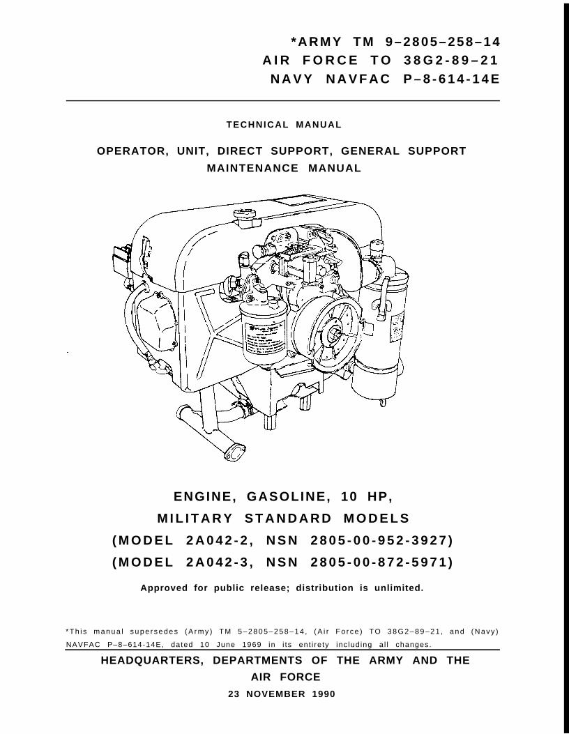
*ARMY TM 9–2805–258–14 A I R F O R C E T O 3 8 G 2 - 8 9 – 2 1
N A V Y N A V F A C P – 8 - 6 1 4 - 1 4 E
TECHNICAL MANUAL
OPERATOR, UNIT, DIRECT SUPPORT, GENERAL SUPPORT
MAINTENANCE MANUAL
ENGINE, GASOLINE, 10 HP,
M I L I T A R Y S T A N D A R D M O D E L S
( M O D E L 2 A 0 4 2 - 2 , N S N 2 8 0 5 - 0 0 - 9 5 2 - 3 9 2 7 )
( M O D E L 2 A 0 4 2 - 3 , N S N 2 8 0 5 - 0 0 - 8 7 2 - 5 9 7 1 )
Approved for public release; distribution is unlimited.
* T h i s m a n u a l s u p e r s e d e s ( A r m y ) T M 5 – 2 8 0 5 – 2 5 8 – 1 4 , ( A i r F o r c e ) T O 3 8 G 2 – 8 9 – 2 1 , a n d ( N a v y )
NAVFAC P–8–614-14E, dated 10 June 1969 in i ts ent i re ty inc lud ing a l l changes.
HEADQUARTERS, DEPARTMENTS OF THE ARMY AND THE
AIR FORCE
23 NOVEMBER 1990
ARMY TM 9-2805-258-14AIR FORCE TO 38G2-89-21
NAVY NAVFAC P-8-614-14EC2
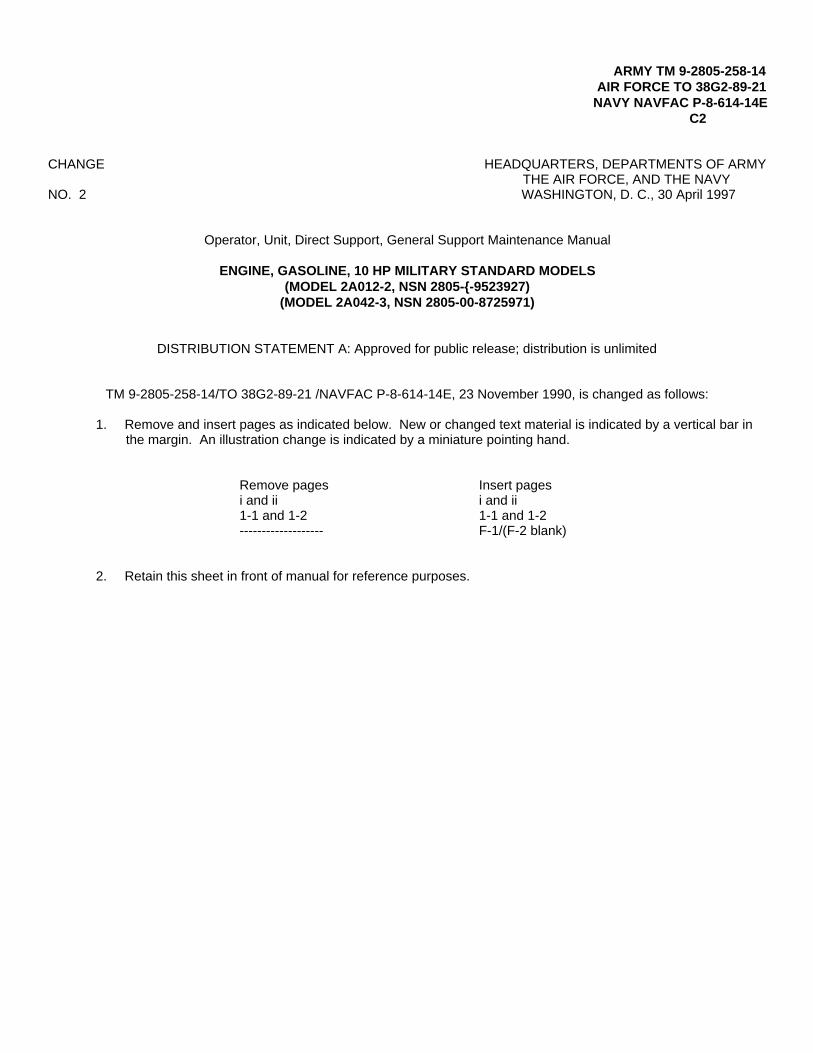
CHANGE HEADQUARTERS, DEPARTMENTS OF ARMYTHE AIR FORCE, AND THE NAVY
NO. 2 WASHINGTON, D. C., 30 April 1997
Operator, Unit, Direct Support, General Support Maintenance Manual
ENGINE, GASOLINE, 10 HP MILITARY STANDARD MODELS(MODEL 2A012-2, NSN 2805-{-9523927)
(MODEL 2A042-3, NSN 2805-00-8725971)
DISTRIBUTION STATEMENT A: Approved for public release; distribution is unlimited
TM 9-2805-258-14/TO 38G2-89-21 /NAVFAC P-8-614-14E, 23 November 1990, is changed as follows:
1. Remove and insert pages as indicated below. New or changed text material is indicated by a vertical bar inthe margin. An illustration change is indicated by a miniature pointing hand.
Remove pages Insert pagesi and ii i and ii1-1 and 1-2 1-1 and 1-2------------------- F-1/(F-2 blank)
2. Retain this sheet in front of manual for reference purposes.
ARMY TM 9-2805-258-14AIR FORCE TO 38G2-89-21
NAVY NAVFAC P-8-614-14EC1
CHANGE HEADQUARTERSDEPARTMENTS OF THE ARMY, AIR FORCE AND THE NAVY
NO. 1 WASHINGTON, D. C., 31 July 1996
Operator, Unit, Direct Support, and General SupportMaintenance Manual
ENGINE, GASOLINE, 10 HP,MILITARY STANDARD MODELS
(MODEL 2A042-2, NSN 2805-00-952-3927)(MODEL 2A042-3, NSN 2805-00-872-5971)
DISTRIBUTION STATEMENT A: Approved for public release; distribution is unlimited
TM 9-2805-25814/TO 38G2-89-21/NAVFAC P-8-614-14E, 23 November 1990 is changed as follows.
1. The address at the bottom of the cover, before the date, should read "HEADQUARTERS, DEPARTMENTSOF THE ARMY, AIR FORCE, AND THE NAVY."
2. Remove and insert pages as indicated below. New or changed text material is indicated by a vertical bar inthe margin. An illustration change is indicated by a miniature pointing hand.
Remove pages Insert pagesi and ii i and ii4-107 and 4-108 4-107 and 4-1084-113 and 4-114 4-113 and 1145-33 and 5-34 5-33 and 5-34
3. Retain this sheet in front of manual for reference purposes.
ARMY TM 9-2805-258-14AIR FORCE TO 38G2-89-21NAVFAC P-8-614-14E
C1
By Order of the Secretaries of the Army, Air Force and Navy:
DENNIS J. REIMEROfficial: General, United States Army
Chief of Staff
JOEL B. HUDSONAdministrative Assistant to the
Secretary of the Army03487
RONALD R. FOGELMANGeneral, USAFChief of Staff
HENRY VICCELLIO, JR.General, USAFCommander, Air Force Materiel Command
J.E. BUFFINGTONRear Admiral, CEC, US NavyCommanderNavy Facilities EngineeringCommand
DISTRIBUTION:To be distributed in accordance with DA Form 12-25-E, block no. 0754, requirements for TM 9-2805-258-14.
ARMY TM 9-2805-258-14AIR FORCE TO 38G2-89-21
NAVY NAVFAC P-8-614-14E
W A R N I N G
Drycleaning solvent, PD-680, used to clean parts is potentially dangerous to personnel
and property. Avoid repeated and prolonged skin contact. Do not use near open flame
or excessive heat. Flash point of solvent is 100-138°F (38-60°C).
W A R N I N G
Serious eye injury can result from the starter rope knot. Wear eye protection when pull
starting engine.
Before starting engine or operating any of the components insure that no loose bars,
tools, or parts are lying in or on any pad of the equipment, as they could cause serious
damage to equipment or bodily injury to personnel.
Never wear loose clothing, or hanging appendages from person or clothing, while
inspecting running engine, moving shafts, or like machinery.
W A R N I N G
If operating the engine or equipment indoors insure that proper ventilation is provided.
Carbon monoxide fumes are a colorless, odorless and deadly gas. These gases could
cause permanent brain damage or death, if highly concentrated in any certain area. The
symptoms are headache, dizziness, loss of muscular control, apparent drowsiness and
coma. If exposure symptoms exist, move afflicted person or personnel to properly
ventilated area and provide artificial respiration, if necessary.
W A R N I N G
Always provide metal-to-metal contact between fuel container and fuel tank, while
refueling, to avoid igniting fuel vapors with a static spark.
Do not refuel while engine is in operation.
Before refueling, insure that adequate fire fighting equipment is serviceable and is
standing by for immediate use in event of fire or explosion.
During engine operation, proper fire fighting equipment should be serviceable and kept
near in the event that fire is developed by electrostatic spark or detonation of the gas
fumes. Do not smoke or use an open flame in the vicinity of these gasoline vapor
hazards .
W A R N I N G
Never touch engine or engine accessories with bare hands during operation, or before
they have cooled sufficiently. Severe burns can be caused through carelessness.
a
ARMY TM 9-2805-258-14AIR FORCE TO 38G2-89-21NAVY NAVFAC P-8-614-14E
W A R N I N G
Do not touch the ignition system harness during starting or while in operation. Severe
shocks or burns could result, and personnel maybe seriously injured.
Disconnect the high tension cables prior to engine maintenance to prevent accidental
starting and severe shock.
W A R N I N G
Operation of the equipment presents a noise hazard to personnel in the area. The noise
level exceeds the allowable limits for unprotected personnel. Wear ear muffs or earplugs
which were fitted by a trained professional.
W A R N I N G
Do not smoke or use an open flame in the vicinity of these gasoline vapor hazards.
b
*ARMY TM 9-2805-258-14AIR FORCE TO 38G2-89-21
NAVY NAVFAC P-8-614-14E
TECHNICAL MANUAL 9-2805-258-14 HEADQUARTERS, DEPARTMENTS OF THE ARMY,TECHNICAL ORDER 38G2-89-21 THE AIR FORCE, AND THE NAVYNAVY NAVFAC P-8-614-14EWASHINGTON, D. C., 23 November 1990
Operator, Unit, Direct Support, General Support Maintenance Manual
ENGINE, GASOUNE, 10 HP MILITARY STANDARD MODELS(MODEL 2A042-2, NSN 2805-00-952-3927)(MODEL 2A042-3, NSN 2805-00-872-5971)
REPORTING ERRORS AND RECOMMENDING IMPROVEMENTS
You can help improve this manual. If you find any mistakes or if you know of a way to improve theseprocedures, please let us know Mail your letter or DA Form 2028 (Recommended Changes toPublications and Blank Forms), or DA Form 20282 located in the back of this manual directly to:Commander, US Army Aviation and Troop Command, ATTN: AMSATIMP, 4300 Goodfellow Blvd., St.Louis, MO 631201798. You may also submit your recommended changes by E-mail directly to<mpmt%[email protected]>. A reply will be furnished directly to you. Instructions forsending an electronic 2028 may be found at the back of this manual immediately preceding the hard copy2028.
For Air Force, submit AFTO Form, 22 (Technical Order System Publication Improvement Report andReply) in accordance with paragraph 65, Section VI, TO. 0051. Forward direct to Commander, SanAntonio Air Logistic Center, ATTN: SA-ALC-MMDDA, Kelly Air Force Base. Texas 78241-5000.
For Navy, mail comments to the Commander, Naval Construction Battalion Center, ATTN: Code 15741 F,Bldg 43, Port Hueneme, California 93043-5000
DISTRIBUTION STATEMENT A: Approved for public release; distribution is unlimited
TABLE OF CONTENTS
PAGECHAPTER 1 INTRODUCTION ............................................................................................................................. 1-1
Section I General Information ......................................................................................................................... 1-1Section II Equipment Description and Data..................................................................................................... 1-2Section III Principles of Operation .................................................................................................................... 1-6
CHAPTER 2 OPERATING INSTRUCTIONS ....................................................................................................... 2-1Section I Description and Use of Operator’s Controls an Indicators ............................................................. 2-1Section II Preventive Maintenance Checks an Services ................................................................................ 2-4Section III Operation Under Usual Conditions.................................................................................................. 2-7Section IV Operation Under Unusual Conditions.............................................................................................. 2-7
*This manual supersedes (Army) TM 5-2805-258-14, (Air Force) TO 38G2-89-21, (Navy) NAVFAC P-8-614-14E dated 10June 1969 including all changes.
Change 2 i
ARMY TM 9-2805-258-14AIR FORCE TO 38G2-89-21NAVY NAVFAC P-8-614-14E
TABLE OF CONTENTS (cont)
CHAPTER 3 OPERATOR’S MAINTENANCE INSTRUCTIONS .......................................................................... 3-1Section I Lubrication Instructions................................................................................................................... 3-1Section II Operator Troubleshooting Procedures ............................................................................................ 3-1Section III Operator’s Maintenance .................................................................................................................. 3-3
CHAPTER 4 UNIT MAINTENANCE ..................................................................................................................... 4-1Section I Repair Parts, Special Tools, Test, Measurement, Diagnostic Equipment (TMDE);
and Support Equipment ................................................................................................................... 4-1Section II Service Upon Receipt ...................................................................................................................... 4-2Section III Unit Preventive Maintenance Checks and Services (PMCS) .......................................................... 4-2Section IV Unit Troubleshooting........................................................................................................................ 4-3Section V Unit Maintenance Procedures ......................................................................................................... 4-7Section VI Preparation for Shipment or Storage............................................................................................... 4-117
CHAPTER 5 DIRECT SUPPORT MAINTENANCE INSTRUCTIONS ................................................................. 5-1Section I Repair Parts, Special Tools, Test, Measurement, Diagnostic Equipment (TMDE):
and Support Equipment ................................................................................................................... 5-1Section II Direct Support Troubleshooting....................................................................................................... 5-1Section III Direct Support Maintenance Procedures ........................................................................................ 5-4
CHAPTER 6 GENERAL SUPPORT MAINTENANCE INSTRUCTIONS.............................................................. 6-1Section I Repair Parts, Special Tools, Test, Measurement, Diagnostic Equipment (TMDE):
and Support Equipment ................................................................................................................... 6-1Section II General Support Troubleshooting ................................................................................................... 6-1Section III General Support Maintenance Procedures ..................................................................................... 6-3
APPENDIX A REFERENCE................................................................................................................................... A-1
APPENDIX B MAINTENANCE ALLOCATION CHART ......................................................................................... B-1
APPENDIX C COMPONENTS OF END ITEM AND BASIC ISSUE ITEMS ......................................................... C-1
APPENDIX D EXPENDABLE/DURABLE SUPPLIES AND MATERIALS LIST ..................................................... D-1
APPENDIX E TORQUE LIMITS ............................................................................................................................ E-1
APPENDIX F ADDITIONAL AUTHORIZATION LIST .......................................................................................... F-1
INDEX ................................................................................................................................................................ Index-1
ii Change 2
ARMY TM 9-2805-258-14AIR FORCE TO 38G2-89-21
NAVY NAVFAC P-8-614-14E
Figure
N u m b e r
1-1
1-2
2-1
4-1
4 - 2
4 - 3
4 - 4
4 - 5
4 - 6
4 - 7
4 - 8
4 - 9
4 - 1 0
4-11
4 - 1 2
4 - 1 3
4 - 1 4
4 - 1 5
4 - 1 6
4 - 1 7
4 - 1 8
4 - 1 9
4 - 2 0
4-21
4 - 2 2
4 - 2 3
4 - 2 4
4 - 2 5
4 - 2 6
4 - 2 7
4 - 2 8
4 - 2 9
4 - 3 0
4-31
4 - 3 2
4 - 3 3
4 - 3 4
4 - 3 5
4 - 3 6
4 - 3 7
4 - 3 8
4 - 3 9
4 - 4 0
LIST OF ILLUSTRATIONS
Ti t le P a g e
Military Standard Engine . . . . . . . . . . . . . . . . . . . . . . . . . . . . . . . . . . . . . . . . . . . . . . . . . . . . . 1-0
Location and Descriptionof Major Components . . . . . . . . . . . . . . . . . . . . . . . . . . . . . . . . . . . . 1-4
Operator’s Controls and lndicators . . . . . . . . . . . . . . . . . . . . . . . . . . . . . . . . . . . . . . . . . . . . . 2-3
Fuel Filter, Service . . . . . . . . . . . . . . . . . . . . . . . . . . . . . . . . . . . . . . . . . . . . . . . . . . . . . . . ...4-9
Air Cleaner Element, Service.. . . . . . . . . . . . . . . . . . . . . . . . . . . . . . . . . . . . . . . . . . . . . . ...4-11
Air Cleaner Element, Replacement . . . . . . . . . . . . . . . . . . . . . . . . . . . . . . . . . . . . . . . . . . . . . . 4-13
Air Cleaner, Support Bracket and Restriction indicator, Removal and Installation . . . . . . . . . 4-15
Clamps and Hose, Removal and installation . . . . . . . . . . . . . . . . . . . . . . . . . . . . . . . . . . . . . . 4-17
Air Cleaner Elbow, Removal and Installation . . . . . . . . . . . . . . . . . . . . . . . . . . . . . . . . . . . ...4-19
Breather Tube, Removal and installation . . . . . . . . . . . . . . . . . . . . . . . . . . . . . . . . . . . . . . . . . 4-21
Oil Filter Element, Replacement.. . . . . . . . . . . . . . . . . . . . . . . . . . . . . . . . . . . . . . . . . . . . . . . 4-23
Oil Filter, Replacement . . . . . . . . . . . . . . . . . . . . . . . . . . . . . . . . . . . . . . . . . . . . . . . . . . . . . . 4-25
Oil Filter Cover and Studs, Removal and installation . . . . . . . . . . . . . . . . . . . . . . . . . . . . . . . . 4-27
Top Cover, Right and Left Shrouds, and Cylinder Baffles, Removal . . . . . . . . . . . . . . . . . . . . 4-29
Top Cover, Right and Left Shrouds, and Cylinder Baffles, installation . . . . . . . . . . . . . . . . . . 4-31
Oil Pan Cover, Shroud, and Baffle Plate, Removal and installation . . . . . . . . . . . . . . . . . . . . 4-33
Oil Pan Baffle Control Rod, Positioner, and Front Engine Mount, Removal and installation . . 4-35
Oil Lines and Fittings, Removal and Installation . . . . . . . . . . . . . . . . . . . . . . . . . . . . . . . . . . . 4-37
Rocker Box, Hose and Fittings, Removal and installation . . . . . . . . . . . . . . . . . . . . . . . . . . . . 4-39
Pressure Regulating Valve, Removal and installation . . . . . . . . . . . . . . . . . . . . . . . . . . . . . . . 4-41
Crankcase Breather, Removal and Installation . . . . . . . . . . . . . . . . . . . . . . . . . . . . . . . . . . . . 4-43
Low Oil Pressure Shutdown Switch and ’’T’’ Connector, Removal and installation . . . . . . . . . 4-45
Oil Pressure Transmitter, Removal and installation . . . . . . . . . . . . . . . . . . . . . . . . . . . . . . . . . 4-47
Choke Solenoid, Adjustment . . . . . . . . . . . . . . . . . . . . . . . . . . . . . . . . . . . . . . . . . . . . . . . . . . 4-49
Choke Solenoid and Bracket, Removal and installation . . . . . . . . . . . . . . . . . . . . . . . . . . . . . 4-51
Preheater, Removal and installation . . . . . . . . . . . . . . . . . . . . . . . . . . . . . . . . . . . . . . . . . . . . 4-53
Magneto and Gear, Removal . . . . . . . . . . . . . . . . . . . . . . . . . . . . . . . . . . . . . . . . . . . . . . . ...4-55
Magneto and Gear, installation . . . . . . . . . . . . . . . . . . . . . . . . . . . . . . . . . . . . . . . . . . . . . ...4-57
ignition Timing, Adjustment . . . . . . . . . . . . . . . . . . . . . . . . . . . . . . . . . . . . . . . . . . . . . . . . . . . 4-59
Magneto Contacts, Adjustment . . . . . . . . . . . . . . . . . . . . . . . . . . . . . . . . . . . . . . . . . . . . . . . . 4-61
Magneto Contacts, Removal and installation . . . . . . . . . . . . . . . . . . . . . . . . . . . . . . . . . . . . . . 4-63
Condenser, Removal and installation . . . . . . . . . . . . . . . . . . . . . . . . . . . . . . . . . . . . . . . . . . . 4-65
Coil, Removal and installation . . . . . . . . . . . . . . . . . . . . . . . . . . . . . . . . . . . . . . . . . . . . . . . . . 4-67
High Tension Cable, Removal and Installation . . . . . . . . . . . . . . . . . . . . . . . . . . . . . . . . . . . . 4-69
Spark Plug, Removal and installation . . . . . . . . . . . . . . . . . . . . . . . . . . . . . . . . . . . . . . . . . . . 4-71
Starter, Removal and installation. . . . . . . . . . . . . . . . . . . . . . . . . . . . . . . . . . . . . . . . . . . . ...4-73
Regulator-Rectifier, Removal and Installation . . . . . . . . . . . . . . . . . . . . . . . . . . . . . . . . . . . . . 4-75
Govemor/Carburetor Control,Removal and installation . . . . . . . . . . . . . . . . . . . . . . . . . . . . . 4-77
Govemor Control Rod,Adjustment . . . . . . . . . . . . . . . . . . . . . . . . . . . . . . . . . . . . . . . . . . . . . 4-79
Governor Control Rod, Removal and Installation . . . . . . . . . . . . . . . . . . . . . . . . . . . . . . . . . . . 4-81
Governor Oil Tube, Removal and installation . . . . . . . . . . . . . . . . . . . . . . . . . . . . . . . . . . . . . 4-83
Governor, Adjustment . . . . . . . . . . . . . . . . . . . . . . . . . . . . . . . . . . . . . . . . . . . . . . . . . . . . ...4-85
Governor, Removal and installation . . . . . . . . . . . . . . . . . . . . . . . . . . . . . . . . . . . . . . . . . . ...4-87
iii
ARMY TM 9-2805-258-14AIR FORCE TO 38G2-89-21NAVY NAVFAC P-8-614-14E
Figure
N u m b e r
4-41
4 - 4 2
4 - 4 3
4 - 4 4
4 - 4 5
4 - 4 6
4 - 4 7
4 - 4 8
4 - 4 9
4 - 5 0
4-51
4 - 5 2
4 - 5 3
4 - 5 4
4 - 5 5
5-1
5 - 2
5 - 3
5 - 4
5 - 5
5 - 6
5 - 7
5 - 8
5 - 9
5 - 1 0
5-11
5 - 1 2
5 - 1 3
5 - 1 4
5 - 1 5
5 - 1 6
5 - 1 7
5 - 1 8
5 - 1 9
6-1
6 - 2
6 - 3
6 - 4
6 - 5
6 - 6
6 - 7
6 - 8
i v
LIST OF ILLUSTRATIONS (cont)
Ti t le P a g e
Exhaust Manifold and Exhaust Pipe, Removal and Installation . . . . . . . . . . . . . . . . . . . . . . . .4-89
Manual Choke, Removal and lnstaIlation . . . . . . . . . . . . . . . . . . . . . . . . . . . . . . . . . . . . . . . . . 4-91
Carburetor, Adjustment . . . . . . . . . . . . . . . . . . . . . . . . . . . . . . . . . . . . . . . . . . . . . . . . . . . . . . . 4-93
Carburetor, Removal and lnstallaton . . . . . . . . . . . . . . . . . . . . . . . . . . . . . . . . . . . . . . . . . ...4-95
Fuel Line and Fitt ing, Removal and Installatio n . . . . . . . . . . . . . . . . . . . . . . . . . . . . . . . . . . . . 4-97
Fuel Pump, Test . . . . . . . . . . . . . . . . . . . . . . . . . . . . . . . . . . . . . . . . . . . . . . . . . . . . . . . . . . . . 4-99
Fuel Pump, Removal and installation . . . . . . . . . . . . . . . . . . . . . . . . . . . . . . . . . . . . . . . . . . . . 4-101
intake Manifold Assembly, Removal and lnstallation . . . . . . . . . . . . . . . . . . . . . . . . . . . . . . . . 4-103
Rocker Box Cover, Removal and installation . . . . . . . . . . . . . . . . . . . . . . . . . . . . . . . . . . . . . . 4-105
Alternator, Removal and installation . . . . . . . . . . . . . . . . . . . . . . . . . . . . . . . . . . . . . . . . . . . . . 4-107
Wiring Harness, Test, Removal and Installation . . . . . . . . . . . . . . . . . . . . . . . . . . . . . . . . . . . . 4-109
Tachometer Adapter, Replacement . . . . . . . . . . . . . . . . . . . . . . . . . . . . . . . . . . . . . . . . . . ...4-111
Air Breather Reed and Support, Removal and installation . . . . . . . . . . . . . . . . . . . . . . . . . . . . 4-113
Compression, Test . . . . . . . . . . . . . . . . . . . . . . . . . . . . . . . . . . . . . . . . . . . . . . . . . . . . . . . . . . 4-115
Wiring Diagram . . . . . . . . . . . . . . . . . . . . . . . . . . . . . . . . . . . . . . . . . . . . . . . . . . . . . . . . . . . . . 4-116
Flywheel, Removal and installation . . . . . . . . . . . . . . . . . . . . . . . . . . . . . . . . . . . . . . . . . . . . . 5-5
Fan Housing, Removal and installation . . . . . . . . . . . . . . . . . . . . . . . . . . . . . . . . . . . . . . . ...5-7
Oil Pump Gears, Spacer, and Oil Pump Cover, Removal and installation . . . . . . . . . . . . . . . 5-9
Oil Fill Tube and Gage, Replacement . . . . . . . . . . . . . . . . . . . . . . . . . . . . . . . . . . . . . . . . . . . 5-11
Starter Assembly, Repair . . . . . . . . . . . . . . . . . . . . . . . . . . . . . . . . . . . . . . . . . . . . . . . . . . . . . 5-13
Carburetor, Repair . . . . . . . . . . . . . . . . . . . . . . . . . . . . . . . . . . . . . . . . . . . . . . . . . . . . . . . ...5-15
Timing Gear Cover, Removal and Installation . . . . . . . . . . . . . . . . . . . . . . . . . . . . . . . . . . ...5-17
Timing Gear Cover Oil SeaI, Replacement . . . . . . . . . . . . . . . . . . . . . . . . . . . . . . . . . . . . . . . 5-19
Oil Pan, Removal and installation . . . . . . . . . . . . . . . . . . . . . . . . . . . . . . . . . . . . . . . . . . . . . . 5-21
Check Valve, Removal and installation . . . . . . . . . . . . . . . . . . . . . . . . . . . . . . . . . . . . . . . . . . 5-23
Cylinder Head Assembly, Removal . . . . . . . . . . . . . . . . . . . . . . . . . . . . . . . . . . . . . . . . . . ...5-25
Cylinder Head Assembly, Repair. . . . . . . . . . . . . . . . . . . . . . . . . . . . . . . . . . . . . . . . . . . . ...5-27
Cylinder Head Assembly, installation . . . . . . . . . . . . . . . . . . . . . . . . . . . . . . . . . . . . . . . . . . . . 5-29
Rockers, Removal . . . . . . . . . . . . . . . . . . . . . . . . . . . . . . . . . . . . . . . . . . . . . . . . . . . . . . . . . . 5-31
Rockers,lnspection/Repair . . . . . . . . . . . . . . . . . . . . . . . . . . . . . . . . . . . . . . . . . . . . . . . . ...5-32
Rockers, installation . . . . . . . . . . . . . . . . . . . . . . . . . . . . . . . . . . . . . . . . . . . . . . . . . . . . . . . . . 5-33
lntake and Exhaust Valve, Removal and installation . . . . . . . . . . . . . . . . . . . . . . . . . . . . . . . . 5-35
Valve Tappets, Removal and installation . . . . . . . . . . . . . . . . . . . . . . . . . . . . . . . . . . . . . . . . . 5-37
Rear Oil Seal, Replacement . . . . . . . . . . . . . . . . . . . . . . . . . . . . . . . . . . . . . . . . . . . . . . . . . . 5-39
Piston and Connecting Rod, Removal . . . . . . . . . . . . . . . . . . . . . . . . . . . . . . . . . . . . . . . . . . . 6-5
Piston and Connecting Rod, Repair . . . . . . . . . . . . . . . . . . . . . . . . . . . . . . . . . . . . . . . . . . . . . 6-7
Piston and Connecting Rod, installation . . . . . . . . . . . . . . . . . . . . . . . . . . . . . . . . . . . . . . . . . 6-9
Cylinder, Removal and installation. . . . . . . . . . . . . . . . . . . . . . . . . . . . . . . . . . . . . . . . . . . . . . 6-11
Camshaft, Camshaft Gear and Bearing, Removal and installation . . . . . . . . . . . . . . . . . . . . . 6-13
Crankshaft, Removal . . . . . . . . . . . . . . . . . . . . . . . . . . . . . . . . . . . . . . . . . . . . . . . . . . . . . . . . 6-15
Crankshaft, installation . . . . . . . . . . . . . . . . . . . . . . . . . . . . . . . . . . . . . . . . . . . . . . . . . . . . . . . 6-17
Crankcase, Repair . . . . . . . . . . . . . . . . . . . . . . . . . . . . . . . . . . . . . . . . . . . . . . . . . . . . . . . ...6-19

ARMY TM 9-2805-258-14AIR FORCE TO 38G2-89-21NAVY NAVFAC P-8-614-14E
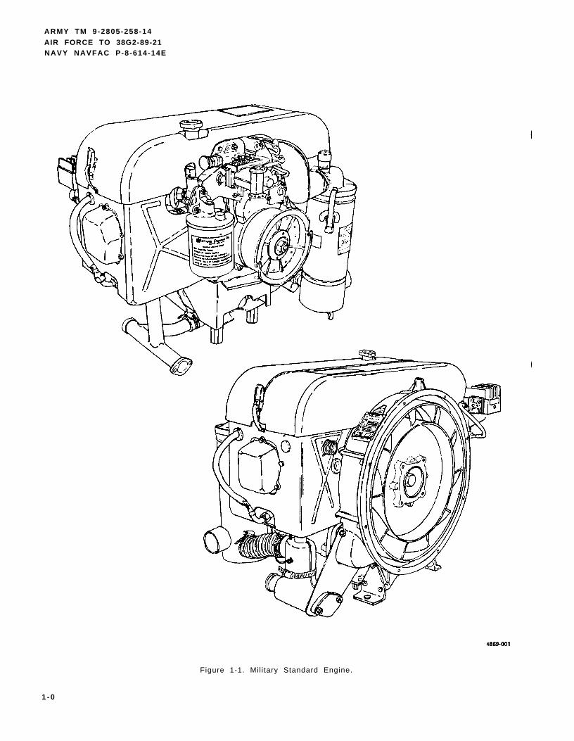
Figure 1-1. Mil itary Standard Engine.
1 - 0
ARMY TM 9-2805-258-14
AIR FORCE TO 38G2-89-21
NAVY NAVFAC P-8-614-14E
C H A P T E R 1
I N T R O D U C T I O N
P a g e
O V E R V I E W 1-1
Section l. General Information . . . . . . . . . . . . . . . . . . . . . . . . . . . . . . . . . . . . . . . . . . . . . . . . 1-1
Section Il. Equipment Description and Data.. . . . . . . . . . . . . . . . . . . . . . . . . . . . . . . . . . . . ...1-2
Section ll l. Principles of Operation . . . . . . . . . . . . . . . . . . . . . . . . . . . . . . . . . . . . . . . . . . . . . ...1-6
O V E R V I E W
This chapter contains general information pertaining to 10 HP Military Standard Engine and its components.
Section 1. GENERAL INFORMATION
Paragraph P a g e
1-1 Scope . . . . . . . . . . . . . . . . . . . . . . . . . . . . . . . . . . . . . . . . . . . . . . . . . . . . . . . . . . . . . . ...1-1
1-2 Consolidated lndex of Army Publications and Blank Forms . . . . . . . . . . . . . . . . . . . . . . . 1-1
1-3 Maintenance Forms, Records, and Reports . . . . . . . . . . . . . . . . . . . . . . . . . . . . . . . . ...1-1
1-4 Reporting Equipment improvement Recommendations (EIR’s) . . . . . . . . . . . . . . . . . . . . 1-2
1-5 Destruction of Army Materiel to Prevent Enemy Use . . . . . . . . . . . . . . . . . . . . . . . . . . . . . 1-2
1 - 6 Preparation for Storage and Shipment . . . . . . . . . . . . . . . . . . . . . . . . . . . . . . . . . . . . ...1-2
1-7 Glossary . . . . . . . . . . . . . . . . . . . . . . . . . . . . . . . . . . . . . . . . . . . . . . . . . . . . . . . . . . . . ...1-2
1-1. SCOPE. This manual contains operator, unit, direct support and general support maintenance for the 10 HP
Military Standard Engine, Models 2A042-2 and -3 (figures 1-1 and 1-2).
1-2. Consolidated Index of Army Publications and Blank Forms. Refer to the latest issue of DA
PAM 25-30 to determine whether there are new edit ions, changes, addit ional publications pertainingtothe
e q u i p m e n t
1-3. Maintenance Forms, Records and Reports.
a . R e p o r t s o f Maintenance and Unsatisfactory E q u i p m e n t . Department of the Army forms and procedures
used for equipment maintenance wil l be those prescribed by DA Pam738-750, as contained in Maintenance
Management Update. Air Force personnel wil l use AFR66-1 Air Force Maintenance Management Policy, for
maintenance reporting and TO-00-35D54 for unsatisfactory equipment reporting.
. .b. Reporting of item and Packaging Discrepanc ies Fill out and forward SF 364 (Report of Discrepancy
in AR 735-11-2/DLAR414-.55/SECNAVINST 4355.18/AFR 400-54/MC0 4430.3J.
c. Transportation Discrepancy Report (TDR) (SF 3 6 1 ) Fi l l out and forward Transportation Discrepancy
Report (TDR) (SF 361) as prescribed in AR 55-28/NAVUSPlNST 4610.33C/AFR 75-18/MCO P4610.19D/
DLAR 4500.15.
1-1
ARMY TM 9-2805-258-14AIR FORCE TO 38G2-89-21NAVY NACFAC P-8-614-14E
1-4. Reporting Equipment Improvement Recommendations (EIR).
a. Army. If your Military Standard Engine needs improvement, let us know. Send us an EIR. You, the user, are theonly one who can tell us what you don’t like about your equipment. Let us know why you don’t like the design orperformance. Put it on an SF 368 (Product Quality Deficiency Report). Mail it to us at: Commander, U.S. Army Aviationand Troop Command, ATTN: AMSATIMDO, 4300 Goodfellow Boulevard, St. Louis, MO 631201798. We will send you areply.
b. Air Force. Air Force personnel are encouraged to submit EIR’s in accordance with AFR 900-4.
c. Navy. Navy personnel are encouraged to submit EIR’s through their local Beneficial Suggestion Program.
1-5. Destruction of Army Materiel to Prevent Enemy Use. Refer to TM 750-244-3 for procedures to destroyequipment to prevent enemy use.
1-6. Preparation for Storage or Shipment. Refer to Chapter 4, Section VI, and TB 740-97-2 for procedure to placethe equipment into storage.
1-7. Glossary. Not applicable
Section II. EQUIPMENT DESCRIPTION AND DATA
Paragraph Page1-8 Equipment Characteristics, Capabilities and Features................................................................. 1-21-9 Location and Description of Major Components (Models 2A042-2 and -3).................................. 1-31-10 Equipment Data ............................................................................................................................ 1-51-11 Differences Between Models........................................................................................................ 1-51-12 Safety, Care, and Handling........................................................................................................... 1-51-13 Corrosion Prevention and Control ................................................................................................ 1-5
1-8. Equipment Characteristics, Capabilities and Features. The Military Standard Engine is an air cooled,horizontally apposed, two cylinder, four cycle gasoline engine. The engine is capable of developing 10 HP at 3600 RPM.
1-2 Change 2
1-9.
1
2
3
4
5
6
7
8
9
1 0
11
1 2
1 3
1 4
1 5
ARMY TM 9-2805-258-14AIR FORCE TO 38G2-89-21
NAVY NAVFAC P-8-614-14E
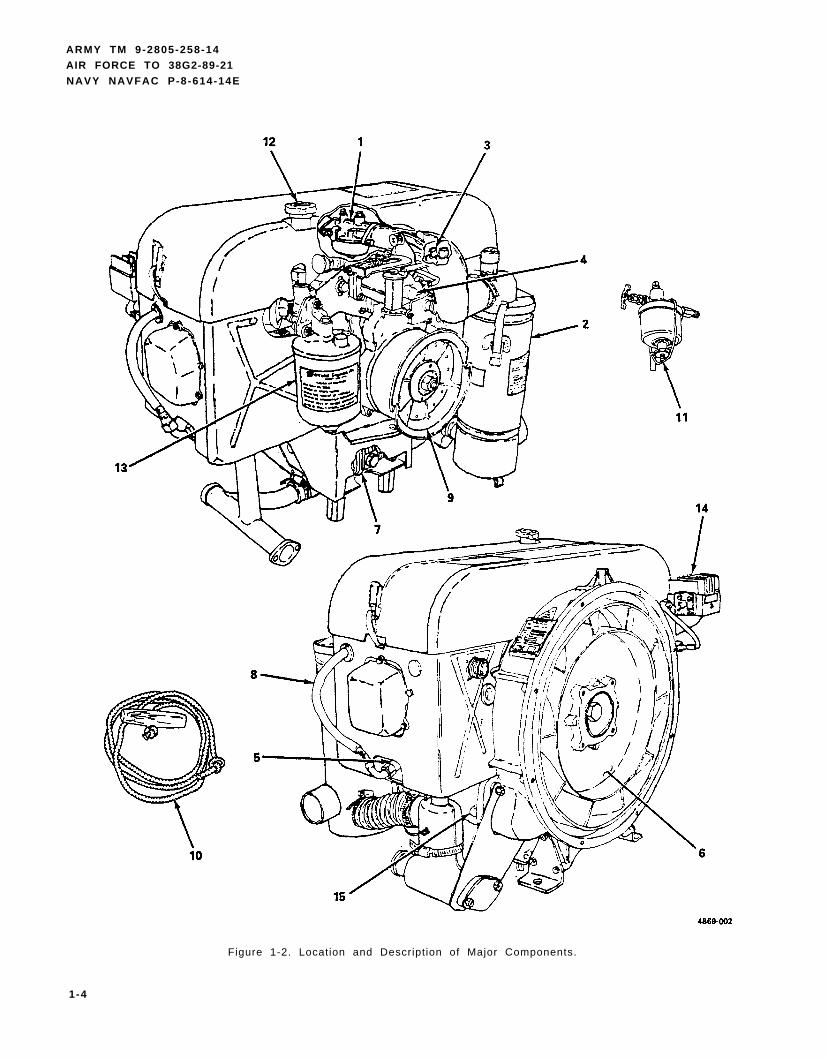
Location and Description of Major Components (Models 2A042-2 and -3) (figure 1-2).
Carburetor - Mixes air and fuel and delivers it to the engine
Air Cleaner - Cleans air going into the carburetor
Fuel Pump - Delivers fuel to carburetor
Governor - Regulates maximum speed of engine
Spark Plug - Delivers spark to air fuel mixture
Flywheel Fan - Provides air for cooling engine during operation
Oil Pan - Serves as a reservoir for engine oil
High Tension Cable - Delivers high voltage electrical charge to spark plug
Starter Rope Pulley and Alternator Rotor - Generates alternating current and provides area to attach starter
rope when pull starting engine
Starter Rope - Used to pull start engine
Fuel Filter - Cleans fuel going to engine
Oil Gage and Filler Tube - Provides the means to check engine oil level and to add oil as needed
Oil Filter - Cleans engine oil
Regulator Rectifier - Changes alternating current generated by alternator into direct current
Electrical Starter - Used to start engine electrically, when engine is connected to an end item with power
supp ly .
1 - 3
ARMY TM 9-2805-258-14AIR FORCE TO 38G2-89-21NAVY NAVFAC P-8-614-14E
1-4
Figure 1-2. Location and Description of Major Components.
ARMY TM 9-2805-258-14
AIR FORCE TO 38G2-89-21
NAVY NAVFAC P-8-614-14E
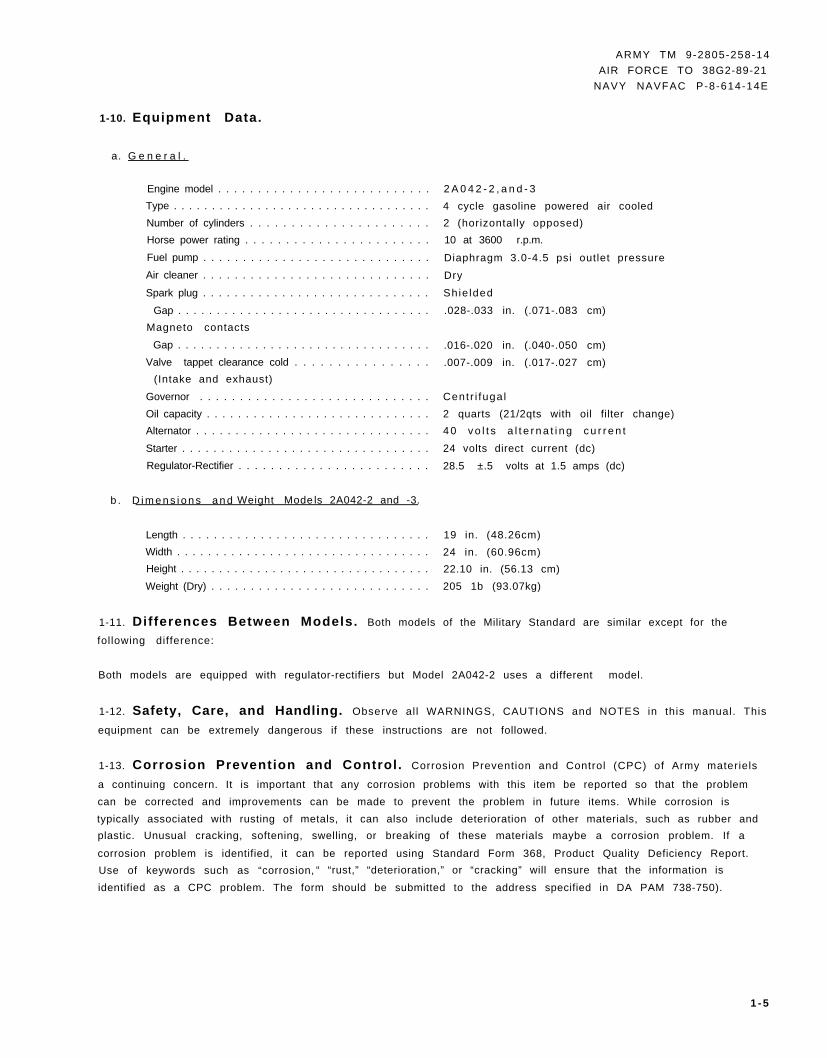
1-10. Equipment Data.
a. G e n e r a l .
Engine model . . . . . . . . . . . . . . . . . . . . . . . . . . .
Type . . . . . . . . . . . . . . . . . . . . . . . . . . . . . . . . . .
Number of cylinders . . . . . . . . . . . . . . . . . . . . . .
Horse power rating . . . . . . . . . . . . . . . . . . . . . . .
Fuel pump . . . . . . . . . . . . . . . . . . . . . . . . . . . . .
Air cleaner . . . . . . . . . . . . . . . . . . . . . . . . . . . . .
Spark plug . . . . . . . . . . . . . . . . . . . . . . . . . . . . .
Gap . . . . . . . . . . . . . . . . . . . . . . . . . . . . . . . . .
Magneto contacts
Gap . . . . . . . . . . . . . . . . . . . . . . . . . . . . . . . . .
Valve tappet clearance cold . . . . . . . . . . . . . . . .
(Intake and exhaust)
Governor . . . . . . . . . . . . . . . . . . . . . . . . . . . . .
Oil capacity . . . . . . . . . . . . . . . . . . . . . . . . . . . . .
Alternator . . . . . . . . . . . . . . . . . . . . . . . . . . . . . .
Starter . . . . . . . . . . . . . . . . . . . . . . . . . . . . . . . .
Regulator-Rectifier . . . . . . . . . . . . . . . . . . . . . . . .
b . D i m e n s i o n s a n d Weight Mode ls 2A042-2 and -3.
Length . . . . . . . . . . . . . . . . . . . . . . . . . . . . . . . .
Width . . . . . . . . . . . . . . . . . . . . . . . . . . . . . . . . .
Height . . . . . . . . . . . . . . . . . . . . . . . . . . . . . . . . .
Weight (Dry) . . . . . . . . . . . . . . . . . . . . . . . . . . . .
2 A 0 4 2 - 2 , a n d - 3
4 cycle gasoline powered air cooled
2 (horizontally opposed)
10 at 3600 r.p.m.
Diaphragm 3.0-4.5 psi outlet pressure
Dry
Shie lded
.028-.033 in. (.071-.083 cm)
.016-.020 in. (.040-.050 cm)
.007-.009 in. (.017-.027 cm)
Cent r i fuga l
2 quarts (21/2qts with oil filter change)
4 0 v o l t s a l t e r n a t i n g c u r r e n t
24 volts direct current (dc)
28.5 ±.5 volts at 1.5 amps (dc)
19 in. (48.26cm)
24 in. (60.96cm)
22.10 in. (56.13 cm)
205 1b (93.07kg)
1-11. Differences Between Models. Both models of the Military Standard are similar except for the
following difference:
Both models are equipped with regulator-rectifiers but Model 2A042-2 uses a different model.
1-12. Safety, Care, and Handling. Observe al l WARNINGS, CAUTIONS and NOTES in this manual. This
equipment can be extremely dangerous if these instructions are not followed.
1-13. Corrosion Prevention and Control. Corrosion Prevention and Control (CPC) of Army materiels
a continuing concern. It is important that any corrosion problems with this item be reported so that the problem
can be corrected and improvements can be made to prevent the problem in future items. While corrosion is
typically associated with rusting of metals, it can also include deterioration of other materials, such as rubber and
plastic. Unusual cracking, softening, swelling, or breaking of these materials maybe a corrosion problem. If a
corrosion problem is identified, it can be reported using Standard Form 368, Product Quality Deficiency Report.
Use of keywords such as “corrosion, “ “rust,” “deterioration,” or “cracking” will ensure that the information is
identified as a CPC problem. The form should be submitted to the address specified in DA PAM 738-750).
1 - 5
ARMY TM 9-2805-258-14AIR FORCE TO 38G2-89-21NAVY NAVFAC P-8-614-14E
Section Ill. PRINCIPLES OF OPERATION
Paragraph P a g e
1-14 Principles of Operation . . . . . . . . . . . . . . . . . . . . . . . . . . . . . . . . . . . . . . . . . . . . . . . . ...1-5
1-14. Principles of Operation.
a. G e n e r a l - . The 10 Hp Military Standard engine is a four cycle two cylinder, air cooled, gasoline powered
internal combustion engine. The engine develops its full rated capacity at a governed 3600 r.p.m.
b. Simplifed Principles of Operation. The engine can either be pull started, or started using the electric
starter. A starter rope pulley mounted on the front of the engine provides a means to connect the starter when pull
starting the engine. When the engine is mounted to an end item that has a separate power supply, the electric
starter can be used to start the engine. An inline fuel filter cleans the fuel supplied to the engine. On the fuel filter
is a fuel cutoff valve, which stops fuel flow to the engine when closed. The engine is equipped with a dry element
air cleaner, with a service indicator, and air inlet control. The service indicator signals when the air cleaner
element requires cleaning. The air inlet control adjusts the amount of heated air entering the air cleaner. An oil
pan baffle directs the flow of cooling air. The baffle is usually set in the back or open position to allow cooling air
to flow around oil pan to help cool the engine. When the baffle is set to the forward or closed position, the cooling
air no longer flows around the oil pan and the engine will run warmer.
c. Deta i led Pr inc ip les of Operat ion.
(1) Fuel system. The fuel system is composed of a fuel filter, fuel pump, fuel line, and carburetor. The fuel
filter is a bowl type with a filtering screen. The screen filters dirt and other foreign materials from the fuel, The
fuel pump draws fuel from an external fuel supply through the fuel filter, and delivers it to the carburetor. The fuel
pump, a diaphragm type, driven by the camshaft. The carburetor mixes the air, from the air cleaner, and the fuel.
This is then delivered to the combustion chamber where it is compressed and burned.
(2) Coo/ing system. The flywheel fan draws cool air into the flywheel fan housing where it is then directed
by the top, left, and right shrouds, cylinder baffles, oil pan baffle, and oil pan cover. The airflows around the
cylinder heads, cylinders, and oil pan and cools the engine.
(3) Air supply. The air cleaner cleans the air going to the carburetor. The dry element air cleaner uses a
dry fiber element to remove dirt from the air. As the element gets dirty, airflow through it decreases and creates a
vacuum in the air cleaner. When airflow decreases too much, the service indicator shows a red signal and
indicates the element requires cleaning.
(4) Speed regulation. Both models of the engine are equipped with a centrifugal f lyweight governor
connected to the carburetor by a control rod. The governor determines the fastest speed at which the engine will
run. The engines are equipped with a throttle control, which overrides the function of the governor. The throttle
control allows the engine speed to be adjusted between idle and full governed speed.
(5) Ignit ion system. A high voltage electrical charge is generated by a magneto, and is delivered to the
spark plug, in the cylinder head, through a shielded cable. The electrical charge creates a spark at the electrode
end of the spark plug. This spark ignites the air/fuel mixture in the cylinder, and generates power.
1-6
ARMY TM 9-2805-258-14
AIR FORCE TO 38G2-89-21NAVY NAVFAC P-8-614-14E
(6) Lubrication. Oil is pumped from the oil pan to the oil filter and then to the engine components. Rocker
box hoses return oil from the cylinder heads back to the oil pan. A crankcase breather, vents oil vapors from the
crankcase into the air supply.
(7) E/ectr ica/ system. The engine is equipped with an alternator and a regulator-rectif ier. The alternator
produces up to 40 volts (ac) during engine operation. The regulator-rectifier converts the output of the alternator
into direct current (dc), which is used to charge the end item battery.
(8) Start ing system. The engine is equipped with both a rope start and an electrical starter system.
1-7/(1-8 blank)

ARMY TM 9-2805-258-14
AIR FORCE TO 38G2-89-21
NAVY NAVFAC P-8-614-14E
CHAPTER 2
OPERATING INSTRUCTIONS
P a g e
OVERVIEW . . . . . . . . . . . . . . . . . . . . . . . . . . . . . . . . . . . . . . . . . . . . . . . . . . . . . ...2-1
Section l. Description and Use of Operator’s Controls and Indicators .. ....... . . . . . . . . . . . . . . . . . . . 2-1
Section Il. Preventive Maintenance Checks and Services (PMCS) . . . . . . . . . . . . . . . . . . . . . . 2-4
Section Il l. Operation Under Usual Conditions . . . . . . . . . . . . . . . . . . . . . . . . . . . . . . . . .....2-7
Section IV. Operation Under Unusual Conditions . . . . . . . . . . . . . . . . . . . . . . . . . . . . . . . . . ...2-7
O V E R V I E W
This chapter contains instructions and procedures required to operate the engine safely and efficiently.
Section l . DESCRIPTION AND USE OF OPERATOR’S CONTROLS AND INDICATORS
Paragraph P a g e
2-1 GeneraI . . . . . . . . . . . . . . . . . . . . . . . . . . . . . . . . . . . . . . . . . . . . . . . . . . . . . . . . . . . ...2-1
2 - 2 Operator’s Controls and lndicators . . . . . . . . . . . . . . . . . . . . . . . . . . . . . . . . . . . . . . ...2-1
2-1. General. This section contains a list of operator controls and indicators and a description of their use.
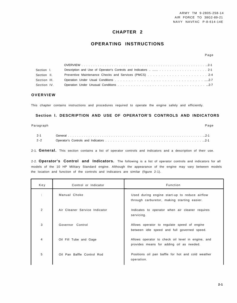
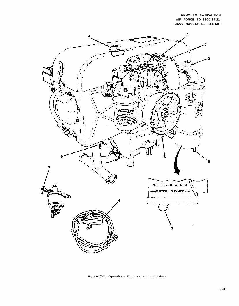
2-2. Operator’s Control and Indicators. The following is a list of operator controls and indicators for all
models of the 10 HP Military Standard engine. Although the appearance of the engine may vary between models
the location and function of the controls and indicators are similar (figure 2-1).
K e y
1
2
3
4
5
Control or Indicator
Manual Choke
Air Cleaner Service Indicator
Governor Control
Oil Fill Tube and Gage
Oil Pan Baffle Control Rod
Funct ion
Used during engine start-up to reduce airf low
through carburetor, making starting easier.
Indicates to operator when air cleaner requires
servicing.
Allows operator to regulate speed of engine
between idle speed and full governed speed.
Allows operator to check oil level in engine, and
provides means for adding oil as needed.
Positions oil pan baffle for hot and cold weather
operat ion.
2-1
ARMY TM 9-2805-258-14AIR FORCE TO 38G2-89-21NAVY NAVFAC P-8-614-14E
K e y
6
7
8
9
Control or Indicator I Funct ion
Starter Rope
Fuel Shutoff Valve
Starter Rope Pulley
Inlet Temperature Control
Used to pull start engine.
Stops fuel flow from fuel filter.
Provides area for starter rope to be attached when
pull starting engine.
Used to adjust amount of cold air entering air
c leaner .
2-2
ARMY TM 9-2805-258-14AIR FORCE TO 38G2-89-21
NAVY NAVFAC P-8-614-14E
Figure 2-1. Operator’s Controls and Indicators.
2 - 3
ARMY TM 9-2805-258-14
AIR FORCE TO 38G2-89-21NAVY NAVFAC P-8-614-14E
Section I l . PREVENTIVE MAINTENANCE CHECKS AND SERVICES (PMCS)
Paragraph P a g e
2 - 3 General . . . . . . . . . . . . . . . . . . . . . . . . . . . . . . . . . . . . . . . . . . . . . . . . . . . . . . . . . . . . ...2-4
2 - 4 Purpose of PMCS Table . . . . . . . . . . . . . . . . . . . . . . . . . . . . . . . . . . . . . . . . . . . . . . . ...2-4
2-5 Explanation of Columns, . . . . . . . . . . . . . . . . . . . . . . . . . . . . . . . . . . . . . . . . . . . . . . . ...2-4
2 - 6 Equipment is Not Ready/Available If Column . . . . . . . . . . . . . . . . . . . . . . . . . . . . . . . ...2-4
2 - 7 Reporting Deficiencies . . . . . . . . . . . . . . . . . . . . . . . . . . . . . . . . . . . . . . . . . . . . . . . . . ...2-5
2-8 Special Instructions . . . . . . . . . . . . . . . . . . . . . . . . . . . . . . . . . . . . . . . . . . . . . . . . . . . ...2-5
2-3. General. Operator PMCS are performed to ensure that the engine is ready for operation at all times.
Perform the checks and services at the specified intervals.
a. Before you operate, perform your before (B) PMCS. Observe al l CAUTIONS and WARNINGS.
b. While you operate, perform your during (D) PMCS. Observe al l CAUTIONS and WARNINGS.
c. After you operate, be sure to perform your after (A) PMCS.
d. lf your equipment fails cooperate, refer to table 3-1, and report deficiencies on DA Form 24O4.
2-4. Purpose of PMCS Table. The purpose of the PMCS table is to provide a systematic method of
inspection and servicing the equipment. In this way, small defects can be detected early before they become a
major problem causing the equipment to fail to complete its mission. The PMCS table is arranged with the
individual PMCS procedures listed in sequence under assigned intervals. The most logical time (before, during, or
after operation) to perform each procedure determines the interval to which it is assigned. Make a habit of doing
the checks in the same order each time and anything wrong will be seen quickly. See paragraphs 2-5 and 2-6 for
an explanation of the columns in table 2-1.
2-5. Explanat ion Of Columns. The following is a l ist of the PMCS table column headings with a description
of the information found in each column.
a. Item No. This column shows the sequence in which the checks and services are to be performed, and is
used to identify the equipment area on the Equipment Inspection and Maintenance Worksheet, DA Form 2404.
b. In terva l . This column shows a dot (0) when each check is to be done.
c. I tem to be Inspected/Procedu res . This column identifies the general area or specific part where the check
or service is to be done, the checks or services to be done, and explains how to do them.
d. Equ ipment is Not Ready/Ava i lab le if. S e e P a r a g r a p h 2 - 6
2-6. Equipment is Not Ready/Available If Column. This column lists conditions that make the
equipment unavailable for use because it is unable to perform its mission, or because it would represent a safety
hazard. Do not accept or operate equipment with a condition in the “Equipment is Not Ready/Available If” column.
2-4
ARMY TM 9-2805-258-14AIR FORCE TO 38G2-89-21
NAVY NAVFAC P-8-614-14E
N O T E
The terms ready/available and mission capable refer to the same status: Equipment is on
hand and is able to perform its combat mission. Refer to DA Pam 738-750.
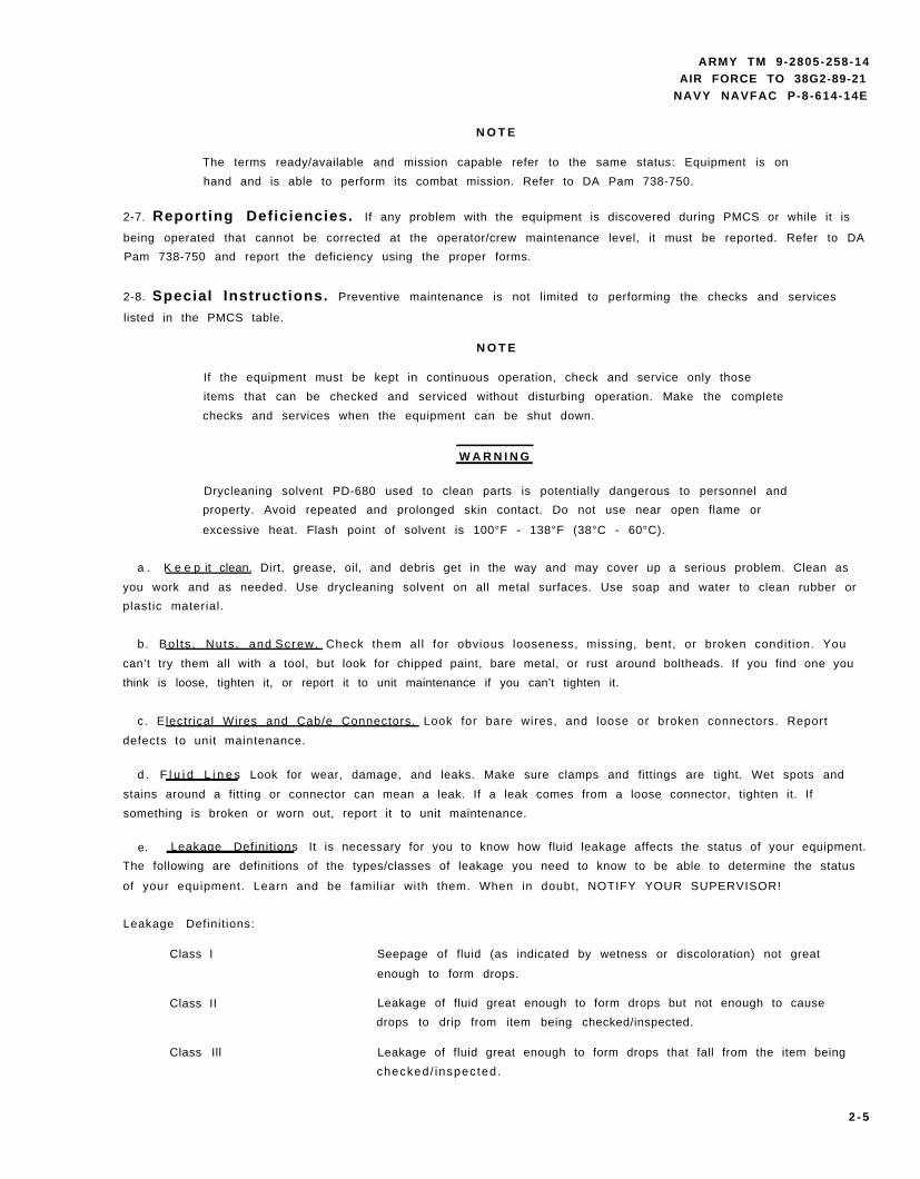
2-7. Reporting Deficiencies. If any problem with the equipment is discovered during PMCS or while it is
being operated that cannot be corrected at the operator/crew maintenance level, it must be reported. Refer to DA
Pam 738-750 and report the deficiency using the proper forms.
2-8. Special Instructions. Preventive maintenance is not limited to performing the checks and services
listed in the PMCS table.
N O T E
If the equipment must be kept in continuous operation, check and service only those
items that can be checked and serviced without disturbing operation. Make the complete
checks and services when the equipment can be shut down.
W A R N I N G
Drycleaning solvent PD-680 used to clean parts is potentially dangerous to personnel and
property. Avoid repeated and prolonged skin contact. Do not use near open flame or
excessive heat. Flash point of solvent is 100°F - 138°F (38°C - 60°C).
a . K e e p it clean. Dirt, grease, oil, and debris get in the way and may cover up a serious problem. Clean as
you work and as needed. Use drycleaning solvent on all metal surfaces. Use soap and water to clean rubber or
plastic material.
b. Bo l ts , Nuts , and Screw. Check them all for obvious looseness, missing, bent, or broken condit ion. You
can’t try them all with a tool, but look for chipped paint, bare metal, or rust around boltheads. If you find one you
think is loose, tighten it, or report it to unit maintenance if you can’t tighten it.
c. Electr ical Wires and Cab/e Connectors. Look for bare wires, and loose or broken connectors. Report
defects to unit maintenance.
d . F l u i d L i n e s Look for wear, damage, and leaks. Make sure clamps and fittings are tight. Wet spots and
stains around a fitting or connector can mean a leak. If a leak comes from a loose connector, tighten it. If
something is broken or worn out, report it to unit maintenance.
e. Leakage Definit ions It is necessary for you to know how fluid leakage affects the status of your equipment.
The following are definitions of the types/classes of leakage you need to know to be able to determine the status
of your equipment. Learn and be famil iar with them. When in doubt, NOTIFY YOUR SUPERVISOR!
Leakage Definit ions:
Class I Seepage of fluid (as indicated by wetness or discoloration) not great
enough to form drops.
Class II
Class Ill
Leakage of fluid great enough to form drops but not enough to cause
drops to drip from item being checked/inspected.
Leakage of fluid great enough to form drops that fall from the item being
checked/ inspected.
2 - 5
ARMY TM 9-2805-258-14AIR FORCE TO 38G2-89-21NAVY NAVFAC P-8-614-14E
CAUTION
Equipment operation is allowable with minor leakage (Class I or ll) of any fluid except
fuel. Of course, consideration must be given to the fluid capacity in the item being
checked/inspected. When in doubt, notify your supervisor.
When operating with Class I or II leaks, continue to check fluid level more often than
required in the PMCS. Parts without fluid will stop working and/or cause equipment
d a m a g e .
Class Ill leaks should be reported to your supervisor or unit maintenance.
Paint ing. Touch-up engine as needed. Refer to TM 43-0139 for specific painting procedures.
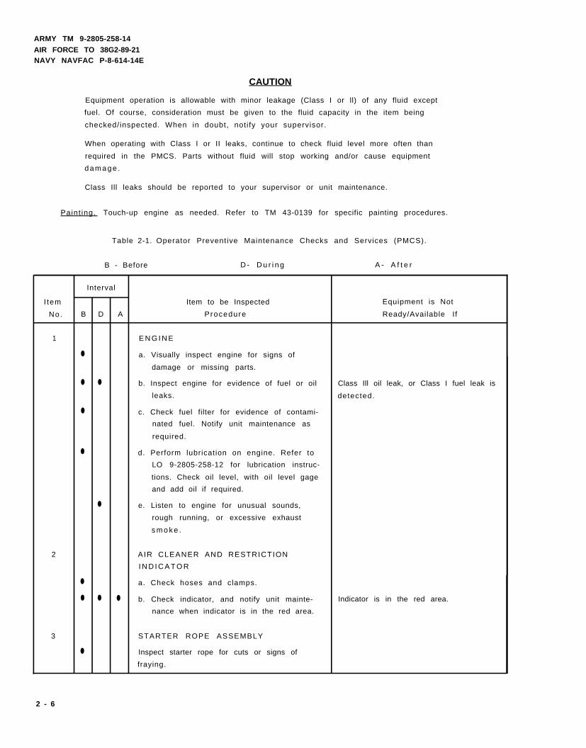
Table 2-1. Operator Preventive Maintenance Checks and Services (PMCS).
B - Before D - D u r i n g A - A f t e r
Interval
I tem Item to be Inspected Equipment is Not
No. B D A Procedure Ready/Available If
1 E N G I N E
● a. Visually inspect engine for signs of
damage or missing parts.
● ● b. Inspect engine for evidence of fuel or oil Class Ill oil leak, or Class I fuel leak is
leaks. detected.
● c. Check fuel filter for evidence of contami-
nated fuel. Notify unit maintenance as
required.
● d. Perform lubrication on engine. Refer to
LO 9-2805-258-12 for lubrication instruc-
tions. Check oil level, with oil level gage
and add oil if required.
● e. Listen to engine for unusual sounds,
rough running, or excessive exhaust
s m o k e .
2 AIR CLEANER AND RESTRICTION
I N D I C A T O R
● a. Check hoses and clamps.
● ● ● b. Check indicator, and notify unit mainte- Indicator is in the red area.
nance when indicator is in the red area.
3 STARTER ROPE ASSEMBLY
● Inspect starter rope for cuts or signs of
fraying.
2 - 6
ARMY TM 9-2805-258-14
AIR FORCE TO 38G2-89-21
NAVY NAVFAC P-8-614-14E
Section Ill. OPERATION UNDER USUAL CONDITIONS
Paragraph P a g e
2-9 Starting Procedures . . . . . . . . . . . . . . . . . . . . . . . . . . . . . . . . . . . . . . . . . . . . . . . . . . . ...2-7
2 - 1 0 Stopping Procedures . . . . . . . . . . . . . . . . . . . . . . . . . . . . . . . . . . . . . . . . . . . . . . . . . . ...2-7
2-9. Starting Procedures. Starting procedures vary depending on the end item on which the engine is
used. Refer to the end item manual for specific starting procedures. The following are general instructions for
operating the engine.
a. Always allow sufficient warm-uptime before applying end item load.
b. Always allow sufficient time for the engine to cool down after removing end item load and before stopping
engine.
c. Provide a sufficient flow of fresh air to the engine to ensure proper engine cooling.
2-10. Stopping Procedures. Stopping procedures vary depending on end item on which the engine is
used. Refer to end item technical manual for specific stopping procedure.
Section IV. OPERATION UNDER UNUSUAL CONDITIONS
Paragraph P a g e
2-11 Operation in Dusty or Sandy Areas... . . . . . . . . . . . . . . . . . . . . . . . . . . . . . . . . . . . . ...2-7
2 - 1 2 Operation in Rainy, Humid, or Salt Air Conditions . . . . . . . . . . . . . . . . . . . . . . . . . . . . . . . 2-8
2 - 1 3 Operation in Extreme Heat . . . . . . . . . . . . . . . . . . . . . . . . . . . . . . . . . . . . . . . . . . . . . ...2-8
2 - 1 4 Operation at Different Altitudes . . . . . . . . . . . . . . . . . . . . . . . . . . . . . . . . . . . . . . . . . . ...2-8
2 - 1 5 Operation in Extreme Cold . . . . . . . . . . . . . . . . . . . . . . . . . . . . . . . . . . . . . . . . . . . . . ...2-8
2-11. Operation in Dusty or Sandy Areas. The procedures for operating the engine are the same as
under usual conditions except for the following special precautions:
a.
b.
c.
d.
Keep fuel, lubrication, ignition, and cooling systems free of dust and sand.
Check air cleaner restriction indicator more often when operating in dusty or sandy areas. Have unit
maintenance service air cleaner element as needed.
In the event of severe dust or sand storms, provide a well protected sheltering device for the engine.
Remove all dust or sand from the engine and inspect for damage.
2 - 7
ARMY TM 9-2805-258-14
AIR FORCE TO 38G2-89-21NAVY NAVFAC P-8-614-14E
b.
2-12. Operation in Rainy, Humid, or Salt Air Conditions. The procedures for operating the engine
are the same as under usual conditions except for the following special precautions:
a. Remove all visible signs of corrosion as soon as possible.
b. Keep fuel lines, and ignition lines as dry as possible.
c. If possible, store engine indoors.
d. Use a thin layer of oil or desiccants to keep corrosion to a minimum.
2-13. Operation in Extreme Heat. The procedures for operating the engine are the same as under normal
condition except for the following special precautions:
a.
b.
c.
Check oil level more often when operating in extreme heat. Use appropriate grade oil, refer to
LO 9-2805-258-12.
Allow engine to cool off longer after removing end item load.
In extreme hot temperatures, the engine will run efficiently but at a reduced horse power rating. For each10° (12.2°C) above 60°F (15.5°), a 1 percent loss of power should be expected.
2-14. Operation at Different Altitudes. The procedures for operating the enginr are the same as under
usaul conditions. The engine will operate at altitudes of up to 5000 feet above sea level but at a reduced horse
power rating. For every 1000 feet above sea level, a 3.5 percent power loss should be expected
2-15. Operation in Extreme Cold. The engine can be operated in temperatures a cold as -25°F (-32°C).
The porcedures for operating the engine are the same as under usaul conditions excepts for the following special
precautions.
a.
c.
Protect the engine from icing. Remove ice and snow from engine as often as possible.
Allow engine sufficient warm-up time before apply end item load.
Use appropriate grade oil, refer to LO 9-2805-258-12.
2 - 8
ARMY TM 9-2805-258-14AIR FORCE TO 38G2-89-21
NAVY NAVFAC P-8-614-14E
CHAPTER 3
OPERATOR’S MAINTENANCE
OVERVIEW . . . . . . . . . . . . . . . . . . . . . . . .
Section l. Lubrication Instructions . . . . . . . . . . . . . . .
Section Il. Operator Troubleshooting Procedures . . . .
Section Il l. Operator’s Maintenance . . . . . . . . . . . . . . .
O V E R V I E W
This chapter contains operator level maintenance instructions.
Section l. LUBRICATION
Paragraph
3-1 General . . . . . . . . . . . . . . . . . . . . . . . . . . . . . . .
INSTRUCTIONS
P a g e
. . . . . . . . . . . . . . . . . . . . . . . . . . . . 3-1
. . . . . . . . . . . . . . . . . . . . . . . . . . . . . . . . 3-1
. . . . . . . . . . . . . . . . . . . . . . . . . . . . . . . . 3-1
. . . . . . . . . . . . . . . . . . . . . . . . . . . . . . . . 3 - 3
INSTRUCTIONS
P a g e
. . . . . . . . . . . . . . . . . . . . . . . . . . . . . . . . 3-1
3-1. General. This section contains operator lubrication instructions.
3-2. Lubr icat ion. Refer to LO 9-2805-258-12 and perform operator level lubrication procedures. Operate the
engine (para. 2-9) for at least 5 minutes, after lubrication. Stop the engine (para. 2-10) and perform operator level
after Operation Preventive Maintenance Checks and Services (PMCS). Air Force personnel use applicable T.O.
35C2-3-1-42C work cards for lubrication instructions.
Section I l . OPERATOR TROUBLESHOOTING PROCEDURES
Paragraph P a g e
3 - 3 General . . . . . . . . . . . . . . . . . . . . . . . . . . . . . . . . . . . . . . . . . . . . . . . . . . . . . . . . . . . . ...3-1
3 - 4 Operator Troubleshooting Procedures.. . . . . . . . . . . . . . . . . . . . . . . . . . . . . . . . . . . . ...3-1
3-3. General. This section contains troubleshooting procedures to determine the probable cause of observed
equipment malfunctions. Inspections are provided to isolate the faulty component and corrective actions are
provided to eliminate the malfunction.
3-4. Operator Troubleshooting Procedures. Refer to the Symptom Index to locate the troubleshooting
procedure for the observed malfunction.
a.
b.
Table 3-1 lists the common malfunctions which you may find during operation of 10 HP Military Standard
Gasoline Engine Models 2A042-2 and -3, and its components. Perform the test/inspections in the order
listed.
This manual cannot list all malfunctions that may occur, nor all tests or inspections find corrective actions. If
a malfunction is not corrected by listed corrective actions, notify your supervisor, and unit maintenance.
3-1
ARMY TM 9-2805-258-14
AIR FORCE TO 38G2-89-21NAVY NAVFAC P-8-614-14E
S Y M P T O M I N D E X
S y m p t o m P a g e
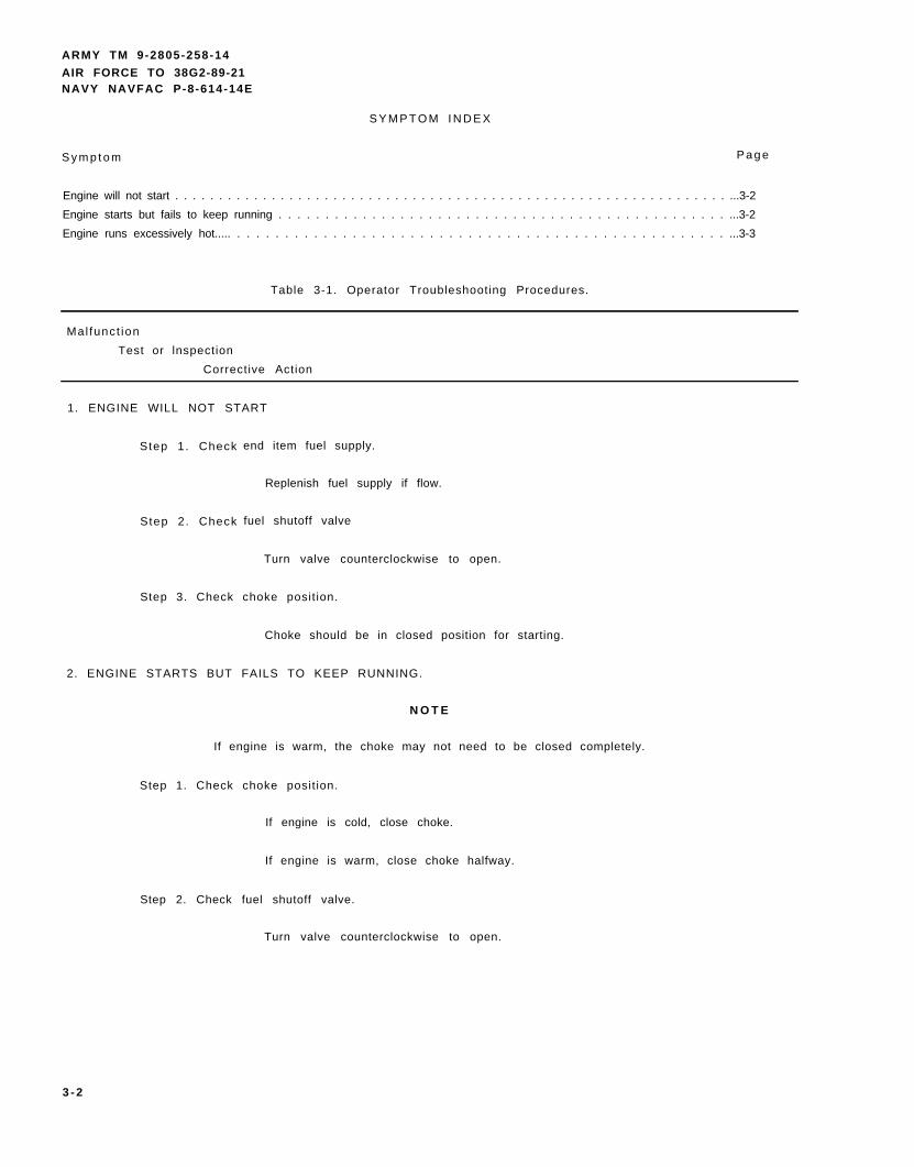
Engine will not start . . . . . . . . . . . . . . . . . . . . . . . . . . . . . . . . . . . . . . . . . . . . . . . . . . . . . . . . . . . . . . . ...3-2
Engine starts but fails to keep running . . . . . . . . . . . . . . . . . . . . . . . . . . . . . . . . . . . . . . . . . . . . . . . . ...3-2
Engine runs excessively hot..... . . . . . . . . . . . . . . . . . . . . . . . . . . . . . . . . . . . . . . . . . . . . . . . . . . . ...3-3
Table 3-1. Operator Troubleshooting Procedures.
Mal funct ion
Test or lnspection
Corrective Action
1. ENGINE WILL NOT START
Step 1. Check
Step 2. Check
end item fuel supply.
Replenish fuel supply if flow.
fuel shutoff valve
Turn valve counterclockwise to open.
Step 3. Check choke posit ion.
Choke should be in closed position for starting.
2. ENGINE STARTS BUT FAILS TO KEEP RUNNING.
N O T E
If engine is warm, the choke may not need to be closed completely.
Step 1. Check choke posit ion.
If engine is cold, close choke.
If engine is warm, close choke halfway.
Step 2. Check fuel shutoff valve.
Turn valve counterclockwise to open.
3 - 2
ARMY TM 9-2805-258-14
AIR FORCE TO 38G2-89-21NAVY NAVFAC P-8-614-14E
Table 3-1. Operator Troubleshooting Procedures (cent).
Mal funct ion
Test or Inspection
Corrective Action
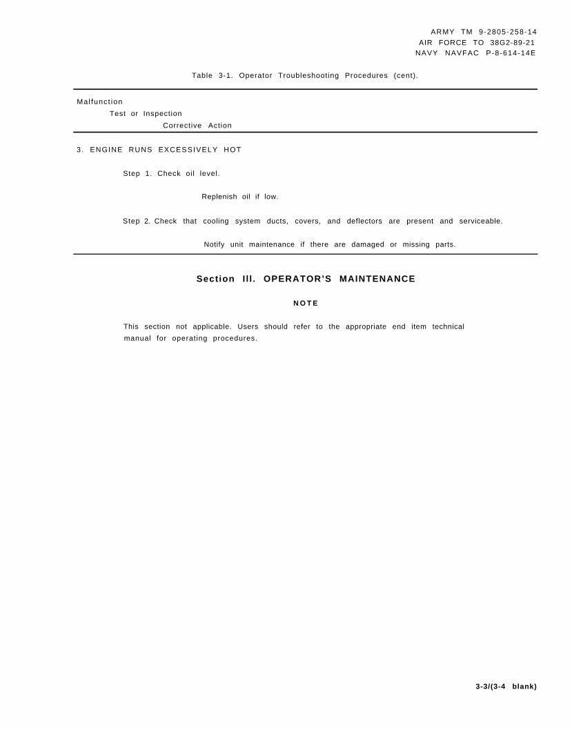
3 . ENGINE RUNS EXCESSIVELY HOT
Step 1. Check oil level.
Replenish oil if low.
Step 2. Check that cooling system ducts, covers, and deflectors are present and serviceable.
Notify unit maintenance if there are damaged or missing parts.
Section I l l . OPERATOR’S MAINTENANCE
N O T E
This section not applicable. Users should refer to the appropriate end item technical
manual for operating procedures.
3-3/(3-4 blank)

Sect ion
O V E R V I E W
Section l.
Section Il.
Section Il l.
Section IV.
Section V.
Section Vl.
O V E R V I E W
ARMY TM 9-2805-258-14
AIR FORCE TO 38G2-89-21
NAVY NAVFAC P-8-614-14E
CHAPTER 4
UNIT MAINTENANCE
P a g e
. . . . . . . . . . . . . . . . . . . . . . . . . . . . . . . . . . . . . . . . . . . . . . . . . . . . . . . . . . . . . . . . . . 4-1
Repair Parts; Special Tools; Test, Measurement, Diagnostic Equipment (TMDE);
and Support Equipment . . . . . . . . . . . . . . . . . . . . . . . . . . . . . . . . . . . . . . . . . . ...4-1
Service Upon Receipt . . . . . . . . . . . . . . . . . . . . . . . . . . . . . . . . . . . . . . . . . . . . . ...4-2
Unit Preventive Maintenance Checks and Services (PMCS) . . . . . . . . . . . . . . . . . . . 4-2
Unit Troubleshooting . . . . . . . . . . . . . . . . . . . . . . . . . . . . . . . . . . . . . . . . . . . . . . ...4-3
Unit Maintenance Procedures . . . . . . . . . . . . . . . . . . . . . . . . . . . . . . . . . . . . . . . ...4-7
Preparation for Shipment or Storage . . . . . . . . . . . . . . . . . . . . . . . . . . . . . . . . . . ...4-117
This chapter contains those maintenance instructions that unit Ievel maintenance is authorized to perform.
Section l . REPAIR PARTS; SPECIAL TOOLS, TEST, MEASUREMENT, DIAGNOSTIC
EQUIPMENT (TMDE); AND SUPPORT EQUIPMENT
Paragraph P a g e
4-1 Common Tools and Test Equipment . . . . . . . . . . . . . . . . . . . . . . . . . . . . . . . . . . . . . . ...4-1
4 - 2 Special Tools, TMDE, and Support Equipment . . . . . . . . . . . . . . . . . . . . . . . . . . . . . . ...4-1
4 - 3 Repair Parts . . . . . . . . . . . . . . . . . . . . . . . . . . . . . . . . . . . . . . . . . . . . . . . . . . . . . . . . . ...4-1
4-1. Common Tools and Equipment. For authorized common tools and equipment, refer to the Modified
Table of Organization and Equipment (MTOE) applicable to your unit.
4-2. Special Tools, TMDE and Support Equipment. For a listing of special tools, TMDE, and support
equipment authorized for use on this equipment, refe rto the Repair Parts and Special Tools List, TM 5-2805-258-
24P, and the maintenance allocation chart (MAC), appendix B of this manual.
4-3. Repair Parts. Repair parts are listed and illustrated in the Repair Parts and Special Tools List for 10 HP
Military Standard Engine TM 5-2805-258-24P.
4-1
ARMY TM 9-2805-258-14AIR FORCE TO 38G2-89-21NAVY NAVFAC P-8-614-14E
Section Il. SERVICE UPON RECEIPT
Paragraph P a g e
4 - 4 Inspection . . . . . . . . . . . . . . . . . . . . . . . . . . . . . . . . . . . . . . . . . . . . . . . . . . . . . . . . . . ...4-2
4 - 5 Lubrication . . . . . . . . . . . . . . . . . . . . . . . . . . . . . . . . . . . . . . . . . . . . . . . . . . . . . . . . . . ...4-2
4 - 6 Testing . . . . . . . . . . . . . . . . . . . . . . . . . . . . . . . . . . . . . . . . . . . . . . . . . . . . . . . . . . . . . ...4-2
4-4.
a.
b.
c.
4-5.
4-6.
Inspection.
Inspect the equipment for damage incurred during shipment. If the equipment has been damaged, report
the damage on SF Form 364, Report of Discrepancy (ROD).
Check the equipment against the packing slip to see if the shipment is complete. Report all discrepancies in
accordance with the instructions of DA PAM 738-750.
Check to see whether the equipment has been modified.
Lubrication. Refer to L0 9-2805-258-12 and perform unit level and operator level lubrication on engine.
Testing. Perform unit level PMCS, and operator Before (B) PMCS before starting engine. Start engine,
para. 2-9, and run for at least 15 minutes. Observe the engine during operation. If any malfunctions arise,
troubleshoot using table 4-2.
Section Ill. UNIT PREVENTIVE MAINTENANCE CHECKS AND SERVICES (PMCS)
P a r a g r a p h P a g e
4 - 7 General . . . . . . . . . . . . . . . . . . . . . . . . . . . . . . . . . . . . . . . . . . . . . . . . . . . . . . . . . . . . ...4-2
4 - 8 PMCS Procedures . . . . . . . . . . . . . . . . . . . . . . . . . . . . . . . . . . . . . . . . . . . . . . . . . . . . ...4-2
4-7. General. Unit level maintenance PMCS are done to ensure that the engine is in top operating condition.
A comprehensive PMCS program reduces equipment downtime and increases the operational readiness of the
engine.
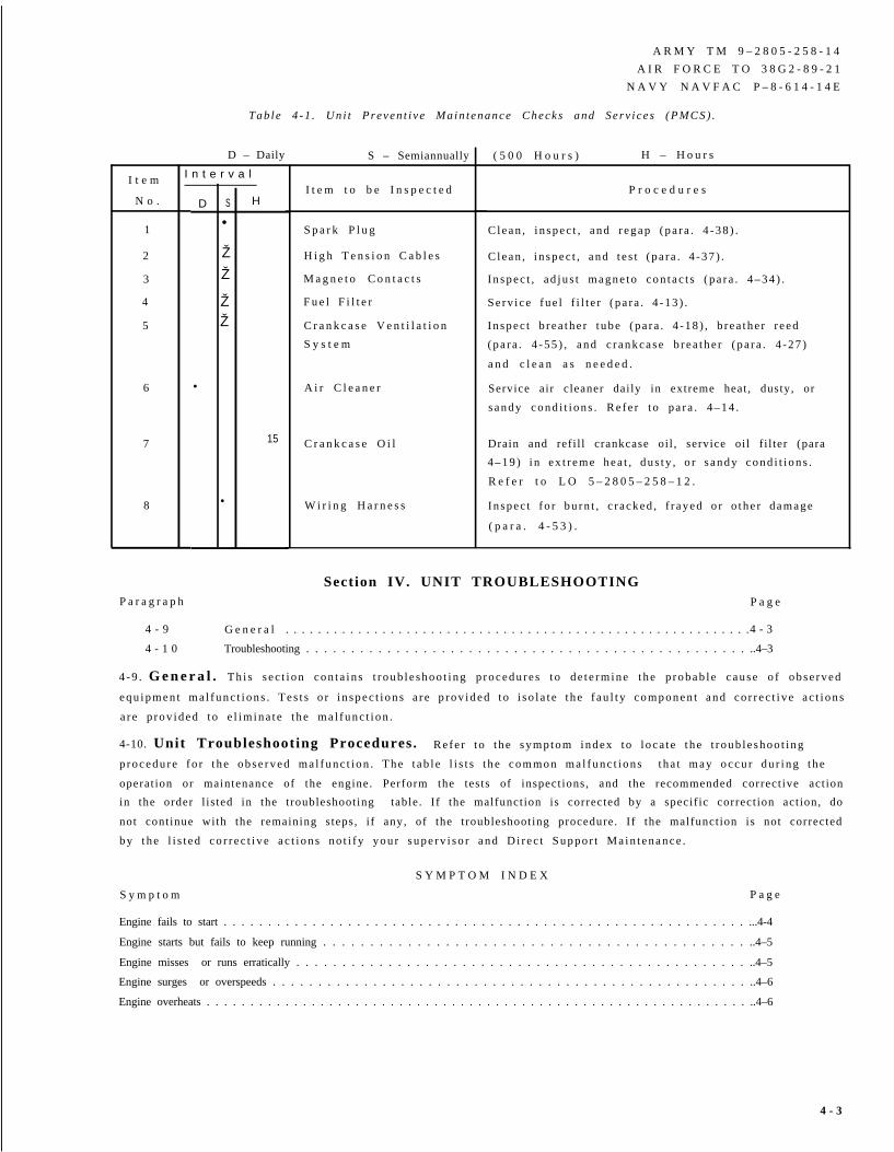
4-8. PMCS Procedures. Unit level PMCS is contained in table 4-1. The numbers in the Item No. column
show the order in which the check or service should be done. These numbers should be used when recording
deficiencies and shortcomings on DA Form 2404, Equipment Inspection and Maintenance Worksheet. The dot (•)
in the Interval column indicates when a check or service should be done, as follows:
4 - 2
I t e m
N o .
I n t e r v a l
D S H
1
2
3
4
5
6
7
8
A R M Y T M 9 – 2 8 0 5 - 2 5 8 - 1 4
A I R F O R C E T O 3 8 G 2 - 8 9 - 2 1
N A V Y N A V F A C P – 8 - 6 1 4 - 1 4 E
T a b l e 4 - 1 . U n i t P r e v e n t i v e M a i n t e n a n c e C h e c k s a n d S e r v i c e s ( P M C S ) .
D – Daily
•
Ž
Ž
ŽŽ
•
15
•
P a r a g r a p h
4 - 9 G e n e r a l
S – Semiannually
I t e m t o b e I n s p e c t e d
S p a r k P l u g
H i g h T e n s i o n C a b l e s
M a g n e t o C o n t a c t s
F u e l F i l t e r
C r a n k c a s e V e n t i l a t i o n
S y s t e m
A i r C l e a n e r
C r a n k c a s e O i l
W i r i n g H a r n e s s
( 5 0 0 H o u r s ) H – H o u r s
P r o c e d u r e s
C l e a n , i n s p e c t , a n d r e g a p ( p a r a . 4 - 3 8 ) .
C l e a n , i n s p e c t , a n d t e s t ( p a r a . 4 - 3 7 ) .
I n s p e c t , a d j u s t m a g n e t o c o n t a c t s ( p a r a . 4 – 3 4 ) .
S e r v i c e f u e l f i l t e r ( p a r a . 4 - 1 3 ) .
I n s p e c t b r e a t h e r t u b e ( p a r a . 4 - 1 8 ) , b r e a t h e r r e e d
( p a r a . 4 - 5 5 ) , a n d c r a n k c a s e b r e a t h e r ( p a r a . 4 - 2 7 )
a n d c l e a n a s n e e d e d .
Service air cleaner dai ly in extreme heat , dusty, or
s a n d y c o n d i t i o n s . R e f e r t o p a r a . 4 – 1 4 .
Drain and refi l l crankcase oil , service oil f i l ter (para
4 – 1 9 ) i n e x t r e m e h e a t , d u s t y , o r s a n d y c o n d i t i o n s .
R e f e r t o L O 5 – 2 8 0 5 – 2 5 8 – 1 2 .
I n s p e c t f o r b u r n t , c r a c k e d , f r a y e d o r o t h e r d a m a g e
( p a r a . 4 - 5 3 ) .
Section IV. UNIT TROUBLESHOOTINGP a g e
. . . . . . . . . . . . . . . . . . . . . . . . . . . . . . . . . . . . . . . . . . . . . . . . . . . . . . . . . .4 - 3
4 - 1 0 Troubleshooting . . . . . . . . . . . . . . . . . . . . . . . . . . . . . . . . . . . . . . . . . . . . . . . . . ..4–3
4 - 9 . G e n e r a l . T h i s s e c t i o n c o n t a i n s t r o u b l e s h o o t i n g p r o c e d u r e s t o d e t e r m i n e t h e p r o b a b l e c a u s e o f o b s e r v e d
e q u i p m e n t m a l f u n c t i o n s . T e s t s o r i n s p e c t i o n s a r e p r o v i d e d t o i s o l a t e t h e f a u l t y c o m p o n e n t a n d c o r r e c t i v e a c t i o n s
a r e p r o v i d e d t o e l i m i n a t e t h e m a l f u n c t i o n .
4-10. Unit Troubleshooting Procedures. R e f e r t o t h e s y m p t o m i n d e x t o l o c a t e t h e t r o u b l e s h o o t i n g
p r o c e d u r e f o r t h e o b s e r v e d m a l f u n c t i o n . T h e t a b l e l i s t s t h e c o m m o n m a l f u n c t i o n s t h a t m a y o c c u r d u r i n g t h e
operat ion or maintenance of the engine. Perform the tests of inspect ions, and the recommended correct ive act ion
in the order l is ted in the t roubleshooting table. If the malfunction is corrected by a specif ic correct ion act ion, do
not continue with the remaining steps, i f any, of the t roubleshooting procedure. If the malfunct ion is not corrected
b y t h e l i s t e d c o r r e c t i v e a c t i o n s n o t i f y y o u r s u p e r v i s o r a n d D i r e c t S u p p o r t M a i n t e n a n c e .
S Y M P T O M I N D E X
S y m p t o m P a g e
Engine fails to start . . . . . . . . . . . . . . . . . . . . . . . . . . . . . . . . . . . . . . . . . . . . . . . . . . . . . . . . . . . ...4-4
Engine starts but fails to keep running . . . . . . . . . . . . . . . . . . . . . . . . . . . . . . . . . . . . . . . . . . . . . ..4–5
Engine misses or runs erratically . . . . . . . . . . . . . . . . . . . . . . . . . . . . . . . . . . . . . . . . . . . . . . . . . ..4–5
Engine surges or overspeeds . . . . . . . . . . . . . . . . . . . . . . . . . . . . . . . . . . . . . . . . . . . . . . . . . . . . ..4–6
Engine overheats . . . . . . . . . . . . . . . . . . . . . . . . . . . . . . . . . . . . . . . . . . . . . . . . . . . . . . . . . . . . . . ..4–6
4 - 3
ARMY TM 9-2805-258-14
AIR FORCE TO 38G2-89-21NAVY NAVFAC P-8-614-14E
S Y M P T O M I N D E X
S y m p t o m P a g e
Engine oil consumption excessive . . . . . . . . . . . . . . . . . . . . . . . . . . . . . . . . . . . . . . . . . . . . . . . . . . . . . . 4-6
Engine lacks power . . . . . . . . . . . . . . . . . . . . . . . . . . . . . . . . . . . . . . . . . . . . . . . . . . . . . . . . . . . . . . . . ..4-6
Table 4-2. Unit Troubleshooting Procedures.
Mal funct ion
Test or lnspection
Corrective Action
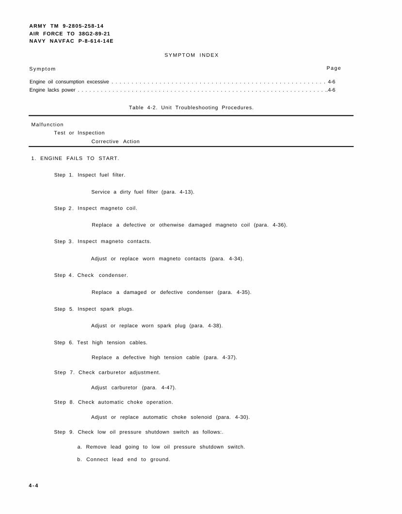
1. ENGINE FAILS TO START.
Step 1.
Step 2 .
Step 3 .
Step 4 .
Step 5.
Step 6.
Inspect fuel filter.
Service a dirty fuel filter (para. 4-13).
Inspect magneto coil.
Replace a defective or othenwise damaged magneto coil (para. 4-36).
Inspect magneto contacts.
Adjust or replace worn magneto contacts (para. 4-34).
Check condenser.
Replace a damaged or defective condenser (para. 4-35).
Inspect spark plugs.
Adjust or replace worn spark plug (para. 4-38).
Test high tension cables.
Replace a defective high tension cable (para. 4-37).
Step 7. Check carburetor adjustment.
Adjust carburetor (para. 4-47).
Step 8. Check automatic choke operation.
Adjust or replace automatic choke solenoid (para. 4-30).
Step 9. Check low oil pressure shutdown switch as follows:.
a. Remove lead going to low oil pressure shutdown switch.
b. Connect lead end to ground.
4 - 4
ARMY TM 9-2805-258-14AIR FORCE TO 38G2-89-21
NAVY NAVFAC P-8-614-14E
Table 4-2. Unit Troubleshooting Procedures (cent).
Mal funct ion
Test or Inspection
Corrective Action
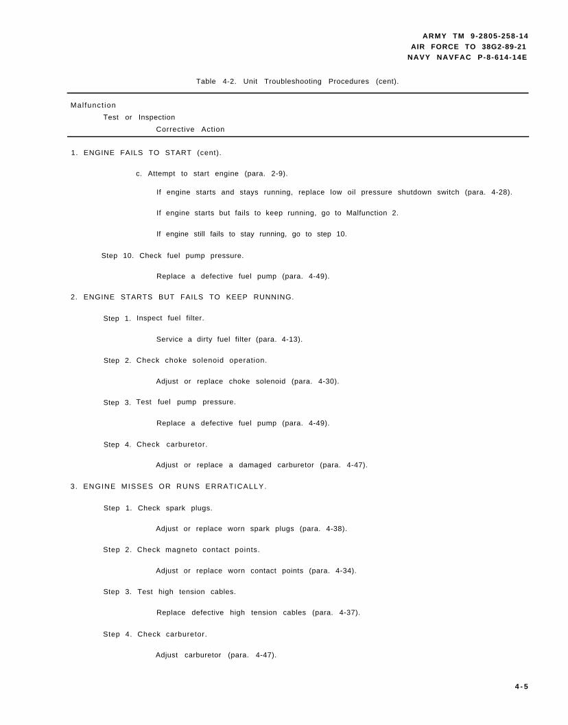
1. ENGINE FAILS TO START (cent).
c. Attempt to start engine (para. 2-9).
If engine starts and stays running, replace low oil pressure shutdown switch (para. 4-28).
If engine starts but fails to keep running, go to Malfunction 2.
If engine still fails to stay running, go to step 10.
Step 10. Check fuel pump pressure.
Replace a defective fuel pump (para. 4-49).
2. ENGINE STARTS BUT FAILS TO KEEP RUNNING.
Step 1.
Step 2.
Step 3.
Step 4.
Inspect fuel filter.
Service a dirty fuel filter (para. 4-13).
Check choke solenoid operation.
Adjust or replace choke solenoid (para. 4-30).
Test fuel pump pressure.
Replace a defective fuel pump (para. 4-49).
Check carburetor.
Adjust or replace a damaged carburetor (para. 4-47).
3 . ENGINE MISSES OR RUNS ERRATICALLY.
Step 1. Check spark plugs.
Adjust or replace worn spark plugs (para. 4-38).
Step 2. Check magneto contact points.
Adjust or replace worn contact points (para. 4-34).
Step 3. Test high tension cables.
Replace defective high tension cables (para. 4-37).
Step 4. Check carburetor.
Adjust carburetor (para. 4-47).
4 - 5
ARMY TM 9-2805-258-14AIR FORCE TO 38G2-89-21NAVY NAVFAC P-8-614-14E
Table 4-2. Unit Troubleshooting Procedures (cent).
Mal funct ion
Test or Inspection
Corrective Act ion
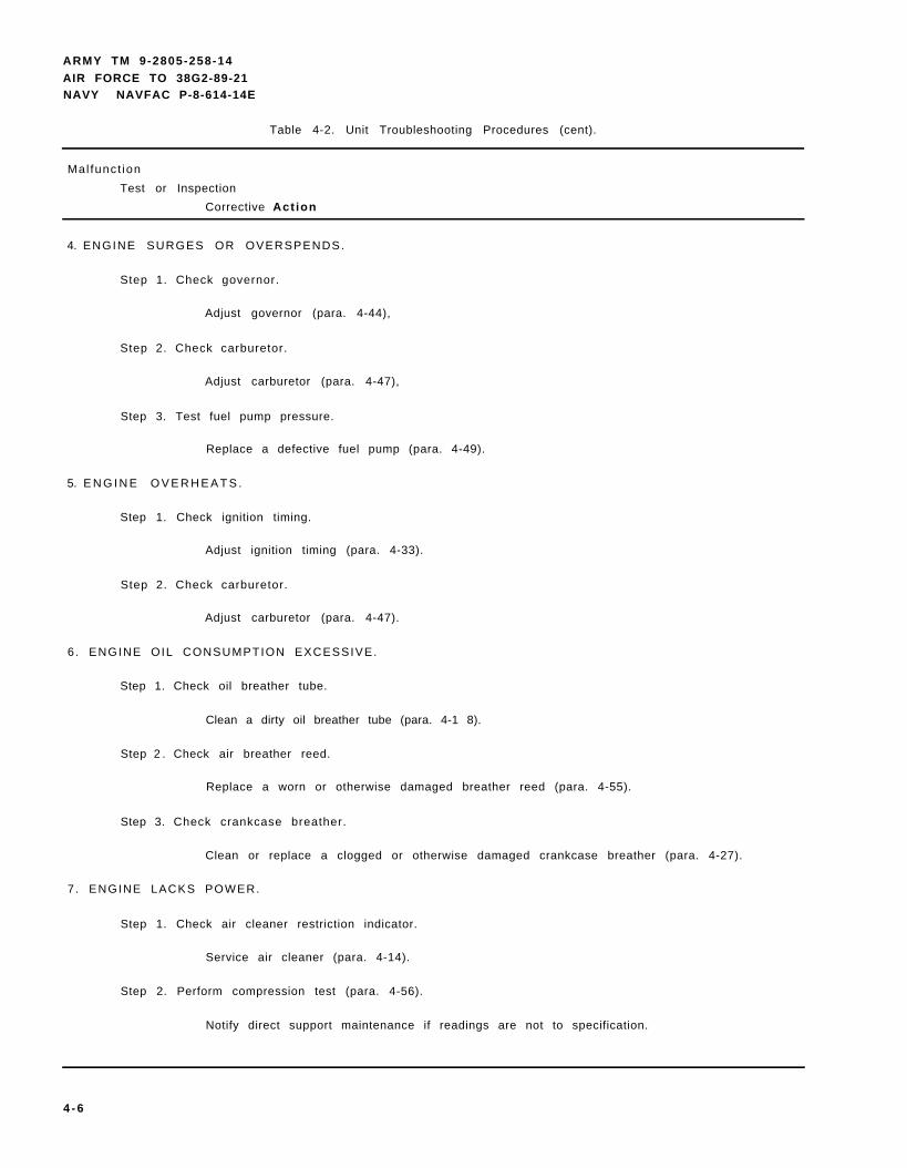
4. ENGINE SURGES OR OVERSPENDS.
Step 1. Check governor.
Adjust governor (para. 4-44),
Step 2. Check carburetor.
Adjust carburetor (para. 4-47),
Step 3. Test fuel pump pressure.
Replace a defective fuel pump (para. 4-49).
5. E N G I N E O V E R H E A T S .
Step 1. Check ignition timing.
Adjust ignition timing (para. 4-33).
Step 2. Check carburetor.
Adjust carburetor (para. 4-47).
6 . ENGINE OIL CONSUMPTION EXCESSIVE.
Step 1.
Step 2 .
Step 3.
Check oil breather tube.
Clean a dirty oil breather tube (para. 4-1 8).
Check air breather reed.
Replace a worn or otherwise damaged breather reed (para. 4-55).
Check crankcase breather.
Clean or replace a clogged or otherwise damaged crankcase breather (para. 4-27).
7 . ENGINE LACKS POWER.
Step 1. Check air cleaner restriction indicator.
Service air cleaner (para. 4-14).
Step 2. Perform compression test (para. 4-56).
Notify direct support maintenance if readings are not to specification.
4 - 6
ARMY TM 9-2805-258-14
AIR FORCE TO 38G2-89-21
NAVY NAVFAC P-8-614-14E
Paragraph
4-11
4 - 1 2
4 - 1 3
4 - 1 4
4 - 1 5
4 - 1 6
4 - 1 7
4 - 1 8
4 - 1 9
4 - 2 0
4-21
4 - 2 2
4 - 2 3
4 - 2 4
4 - 2 5
4 - 2 6
4 - 2 7
4 - 2 8
4 - 2 9
4 - 3 0
4-31
4 - 3 2
4 - 3 3
4 - 3 4
4 - 3 5
4 - 3 6
4 - 3 7
4 - 3 8
4 - 3 9
4 - 4 0
4-41
4 - 4 2
4 - 4 3
4 - 4 4
4 - 4 5
4 - 4 6
4 - 4 7
4 - 4 8
4 - 4 9
4 - 5 0
4-51
4 - 5 2
4 - 5 3
4 - 5 4
4 - 5 5
4 - 5 6
Section V. UNIT MAINTENANCE PROCEDURES
P a g e
General . . . . . . . . . . . . . . . . . . . . . . . . . . . . . . . . . . . . . . . . . . . . . . . . . . . . . . . . . . . ...4-8
Painting . . . . . . . . . . . . . . . . . . . . . . . . . . . . . . . . . . . . . . . . . . . . . . . . . . . . . . . . . . . ...4-8
Fuel Filter . . . . . . . . . . . . . . . . . . . . . . . . . . . . . . . . . . . . . . . . . . . . . . . . . . . . . . . . . . ...4-8
Air Cleaner Element . . . . . . . . . . . . . . . . . . . . . . . . . . . . . . . . . . . . . . . . . . . . . . . . . . ...4-10
Air Cleaner, Support Bracket and Restriction Indicator . . . . . . . . . . . . . . . . . . . . . . . . . . 4-14
Clamps and Hoses . . . . . . . . . . . . . . . . . . . . . . . . . . . . . . . . . . . . . . . . . . . . . . . . . . . ...4-16
Air Cleaner Elbow . . . . . . . . . . . . . . . . . . . . . . . . . . . . . . . . . . . . . . . . . . . . . . . . . . . ...4-18
Breather Tube . . . . . . . . . . . . . . . . . . . . . . . . . . . . . . . . . . . . . . . . . . . . . . . . . . . . . . ...4-20
Oil Filter Element . . . . . . . . . . . . . . . . . . . . . . . . . . . . . . . . . . . . . . . . . . . . . . . . . . . . ...4-22
Oil Filter Cover and Studs . . . . . . . . . . . . . . . . . . . . . . . . . . . . . . . . . . . . . . . . . . . . . ...4-26
Top Cover, Right and Left Shrouds and Cylinder Baffles . . . . . . . . . . . . . . . . . . . . . . . . 4-28
Oil Pan Cover, Shroud and Baffle Plate . . . . . . . . . . . . . . . . . . . . . . . . . . . . . . . . . . . ...4-32
Oil Pan Baffle, Control Rod, Positioner and Front Engine Mount . . . . . . . . . . . . . . . ...4-34
Oil Lines and Fittings . . . . . . . . . . . . . . . . . . . . . . . . . . . . . . . . . . . . . . . . . . . . . . . . . ...4-36
Rocker Box Hose and Fittings . . . . . . . . . . . . . . . . . . . . . . . . . . . . . . . . . . . . . . . . . . ...4-38
Pressure Regulator Valve . . . . . . . . . . . . . . . . . . . . . . . . . . . . . . . . . . . . . . . . . . . . . ...4-40
Crankcase Breather . . . . . . . . . . . . . . . . . . . . . . . . . . . . . . . . . . . . . . . . . . . . . . . . . . ...4-42
Low Oil Pressure Shutdown Switch and ’’T’’ Connector . . . . . . . . . . . . . . . . . . . . . . . ...4-44
Oil Pressure Transmitter . . . . . . . . . . . . . . . . . . . . . . . . . . . . . . . . . . . . . . . . . . . . . . ...4-46
Choke Solenoid and Bracket . . . . . . . . . . . . . . . . . . . . . . . . . . . . . . . . . . . . . . . . . . . ...4-48
Preheater . . . . . . . . . . . . . . . . . . . . . . . . . . . . . . . . . . . . . . . . . . . . . . . . . . . . . . . . . . ...4-52
Magneto and Gear . . . . . . . . . . . . . . . . . . . . . . . . . . . . . . . . . . . . . . . . . . . . . . . . . . . ...4-54
Ignition Timing . . . . . . . . . . . . . . . . . . . . . . . . . . . . . . . . . . . . . . . . . . . . . . . . . . . . . . ...4-58
Magneto Contacts . . . . . . . . . . . . . . . . . . . . . . . . . . . . . . . . . . . . . . . . . . . . . . . . . . . ...4-60
Condenser . . . . . . . . . . . . . . . . . . . . . . . . . . . . . . . . . . . . . . . . . . . . . . . . . . . . . . . . . ...4-64
Coil . . . . . . . . . . . . . . . . . . . . . . . . . . . . . . . . . . . . . . . . . . . . . . . . . . . . . . . . . . . . . . . ...4-66
High Tension Cables . . . . . . . . . . . . . . . . . . . . . . . . . . . . . . . . . . . . . . . . . . . . . . . . . ...4-68
Spark Plugs . . . . . . . . . . . . . . . . . . . . . . . . . . . . . . . . . . . . . . . . . . . . . . . . . . . . . . . . ...4-70
Starter . . . . . . . . . . . . . . . . . . . . . . . . . . . . . . . . . . . . . . . . . . . . . . . . . . . . . . . . . . . . ...4-72
Regulator-Rectifier . . . . . . . . . . . . . . . . . . . . . . . . . . . . . . . . . . . . . . . . . . . . . . . . . . . ...4-74
Governor/Carburetor Control.... . . . . . . . . . . . . . . . . . . . . . . . . . . . . . . . . . . . . . . . ...4-76
Governor Control Ro d . . . . . . . . . . . . . . . . . . . . . . . . . . . . . . . . . . . . . . . . . . . . . . . ...4-78
Governo r Oil Tub e . . . . . . . . . . . . . . . . . . . . . . . . . . . . . . . . . . . . . . . . . . . . . . . . . . ...4-82
Governo r . . . . . . . . . . . . . . . . . . . . . . . . . . . . . . . . . . . . . . . . . . . . . . . . . . . . . . . . . ...4-84
Exhaust Manifold and Exhaust Pipe . . . . . . . . . . . . . . . . . . . . . . . . . . . . . . . . . . . . . ...4-88
Manual Choke . . . . . . . . . . . . . . . . . . . . . . . . . . . . . . . . . . . . . . . . . . . . . . . . . . . . . . ...4-90
Carburetor . . . . . . . . . . . . . . . . . . . . . . . . . . . . . . . . . . . . . . . . . . . . . . . . . . . . . . . . . ...4-92
Fuel Line and Fittings . . . . . . . . . . . . . . . . . . . . . . . . . . . . . . . . . . . . . . . . . . . . . . . . ...4-96
Fuel Pump . . . . . . . . . . . . . . . . . . . . . . . . . . . . . . . . . . . . . . . . . . . . . . . . . . . . . . . . . ...4-98
Intake Manifold Assembly . . . . . . . . . . . . . . . . . . . . . . . . . . . . . . . . . . . . . . . . . . . . . ...4-102
Rocker Box Cover . . . . . . . . . . . . . . . . . . . . . . . . . . . . . . . . . . . . . . . . . . . . . . . . . . . ...4-104
Alternator . . . . . . . . . . . . . . . . . . . . . . . . . . . . . . . . . . . . . . . . . . . . . . . . . . . . . . . . . . ...4-106
Wiring Harness . . . . . . . . . . . . . . . . . . . . . . . . . . . . . . . . . . . . . . . . . . . . . . . . . . . . . . . .4-108
Tachometer Adapter . . . . . . . . . . . . . . . . . . . . . . . . . . . . . . . . . . . . . . . . . . . . . . . . . . ...4-110
Air Breather Reed and Support . . . . . . . . . . . . . . . . . . . . . . . . . . . . . . . . . . . . . . . . . ...4-112
Compression Test . . . . . . . . . . . . . . . . . . . . . . . . . . . . . . . . . . . . . . . . . . . . . . . . . . . ...4-114
4 - 7
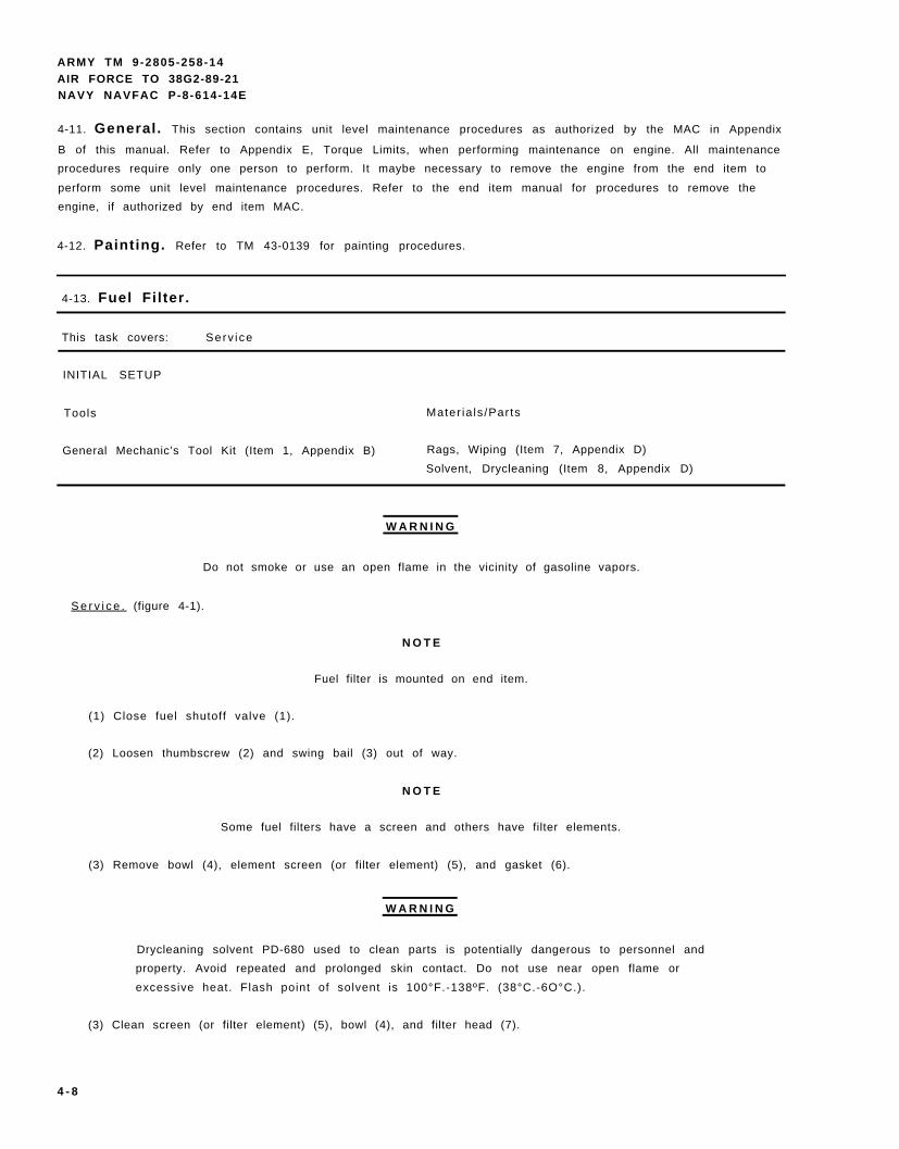
ARMY TM 9-2805-258-14AIR FORCE TO 38G2-89-21NAVY NAVFAC P-8-614-14E
4-11. General. This section contains unit level maintenance procedures as authorized by the MAC in Appendix
B of this manual. Refer to Appendix E, Torque Limits, when performing maintenance on engine. All maintenance
procedures require only one person to perform. It maybe necessary to remove the engine from the end item to
perform some unit level maintenance procedures. Refer to the end item manual for procedures to remove the
engine, if authorized by end item MAC.
4-12. Painting. Refer to TM 43-0139 for painting procedures.
4-13. Fuel Filter.
This task covers: Serv ice
INITIAL SETUP
Tools Mater ia ls /Par ts
General Mechanic’s Tool Kit (Item 1, Appendix B) Rags, Wiping (Item 7, Appendix D)
Solvent, Drycleaning (Item 8, Appendix D)
W A R N I N G
Do not smoke or use an open flame in the vicinity of gasoline vapors.
S e r v i c e . (figure 4-1).
N O T E
Fuel filter is mounted on end item.
(1) Close fuel shutoff valve (1).
(2) Loosen thumbscrew (2) and swing bail (3) out of way.
N O T E
Some fuel filters have a screen and others have filter elements.
(3) Remove bowl (4), element screen (or filter element) (5), and gasket (6).
W A R N I N G
Drycleaning solvent PD-680 used to clean parts is potentially dangerous to personnel and
property. Avoid repeated and prolonged skin contact. Do not use near open flame or
excessive heat. Flash point of solvent is 100°F.-138ºF. (38°C.-6O°C.).
(3) Clean screen (or filter element) (5), bowl (4), and filter head (7).
4 - 8
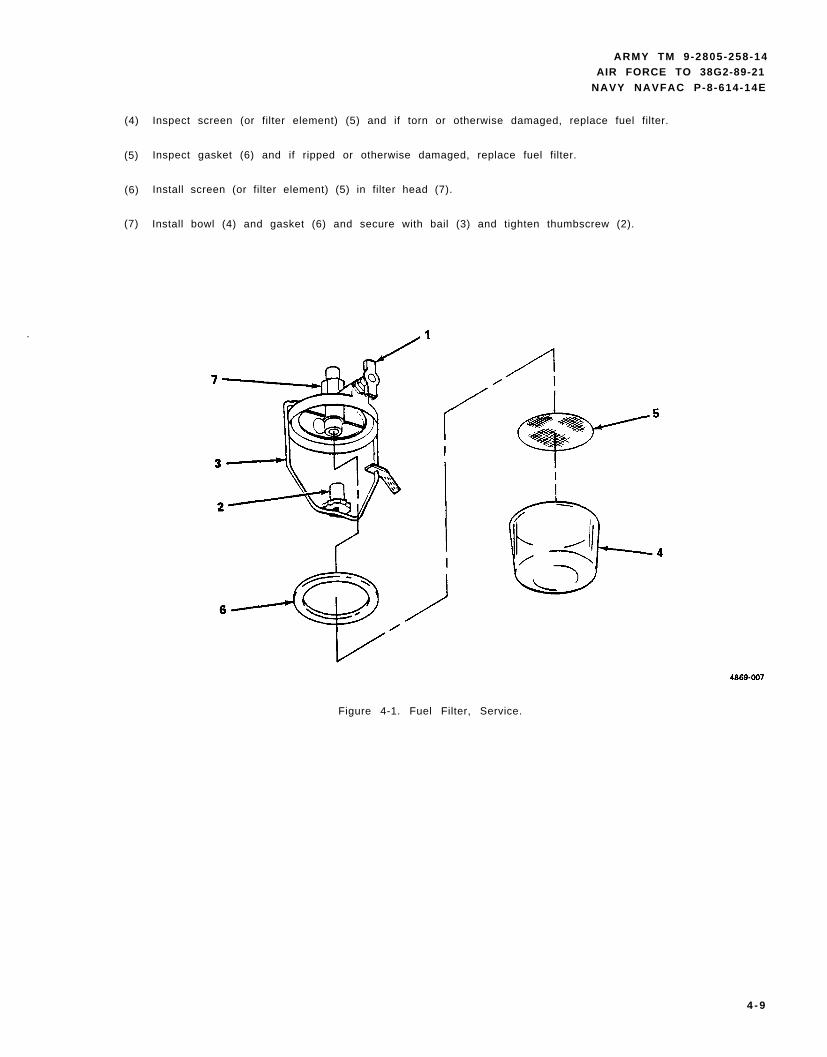
(4)
(5)
(6)
(7)
.
ARMY TM 9-2805-258-14AIR FORCE TO 38G2-89-21
NAVY NAVFAC P-8-614-14E
Inspect screen (or filter element) (5) and if torn or otherwise damaged, replace fuel filter.
Inspect gasket (6) and if ripped or otherwise damaged, replace fuel filter.
Install screen (or filter element) (5) in filter head (7).
Install bowl (4) and gasket (6) and secure with bail (3) and tighten thumbscrew (2).
Figure 4-1. Fuel Filter, Service.
4 - 9
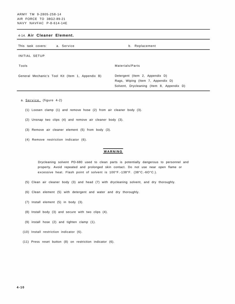
ARMY TM 9-2805-258-14
AIR FORCE TO 38G2-89-21NAVY NAVFAC P-8-614-14E
4-14. Air Cleaner Element.
This task covers: a . Serv ice b. Replacement
INITIAL SETUP
Tools Mater ia ls /Par ts
General Mechanic’s Tool Kit (Item 1, Appendix B) Detergent (Item 2, Appendix D)
Rags, Wiping (Item 7, Appendix D)
Solvent, Drycleaning (Item 8, Appendix D)
a. S e r v i c e . ( f igure 4-2)
(1) Loosen clamp (1) and remove hose (2) from air cleaner body (3).
(2) Unsnap two clips (4) and remove air cleaner body (3).
(3) Remove air cleaner element (5) from body (3).
(4) Remove restrict ion indicator (6).
W A R N I N G
Drycleaning solvent PD-680 used to clean parts is potentially dangerous to personnel and
property. Avoid repeated and prolonged skin contact. Do not use near open flame or
excessive heat. Flash point of solvent is 100°F.-138°F. (38°C.-6O°C.).
(5) Clean air cleaner body (3) and head (7) with drycleaning solvent, and dry thoroughly.
(6) Clean element (5) with detergent and water and dry thoroughly.
(7) Install element (5) in body (3).
(8) Install body (3) and secure with two clips (4).
(9) install hose (2) and tighten clamp (1).
(10) Install restrict ion indicator (6).
(11) Press reset button (8) on restriction indicator (6).
4 - 1 0
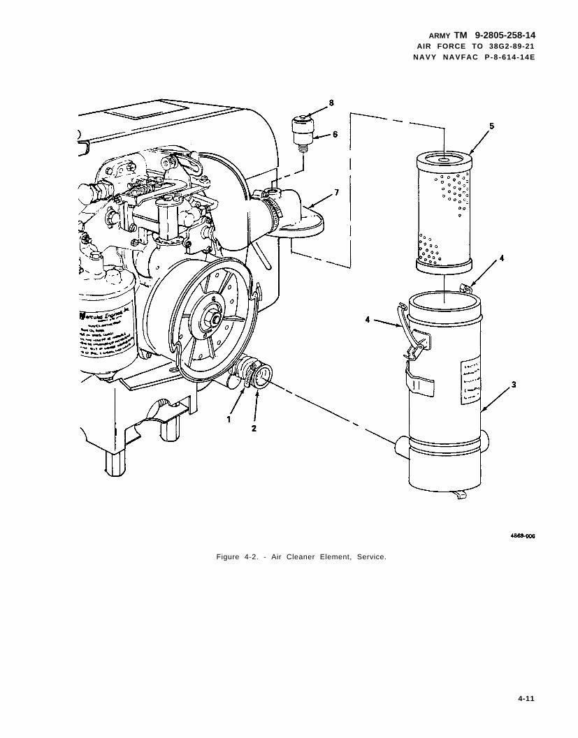
ARMY TM 9-2805-258-14AIR FORCE TO 38G2-89-21
NAVY NAVFAC P-8-614-14E
Figure 4-2. - Air Cleaner Element, Service.
4-11
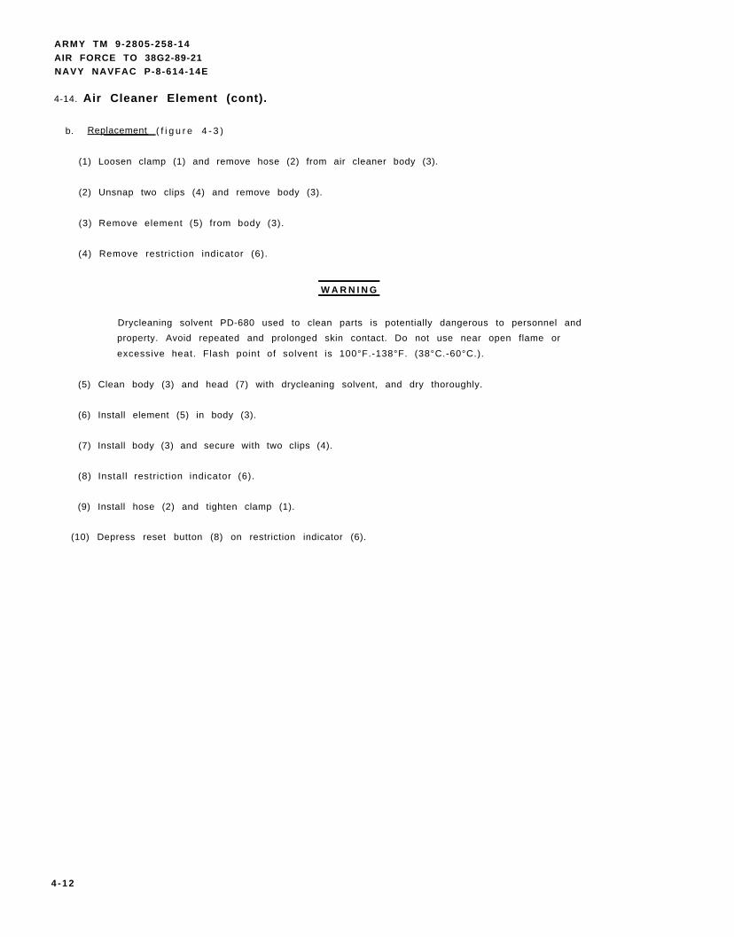
ARMY TM 9-2805-258-14AIR FORCE TO 38G2-89-21NAVY NAVFAC P-8-614-14E
4-14. Air Cleaner Element (cont).
b. Replacement ( f i g u r e 4 - 3 )
(1) Loosen clamp (1) and remove hose (2) from air cleaner body (3).
(2) Unsnap two clips (4) and remove body (3).
(3) Remove element (5) from body (3).
(4) Remove restrict ion indicator (6).
W A R N I N G
Drycleaning solvent PD-680 used to clean parts is potentially dangerous to personnel and
property. Avoid repeated and prolonged skin contact. Do not use near open flame or
excessive heat. Flash point of solvent is 100°F.-138°F. (38°C.-60°C.).
(5) Clean body (3) and head (7) with drycleaning solvent, and dry thoroughly.
(6) Install element (5) in body (3).
(7) Install body (3) and secure with two clips (4).
(8) Install restrict ion indicator (6).
(9) Install hose (2) and tighten clamp (1).
(10) Depress reset button (8) on restriction indicator (6).
4 - 1 2
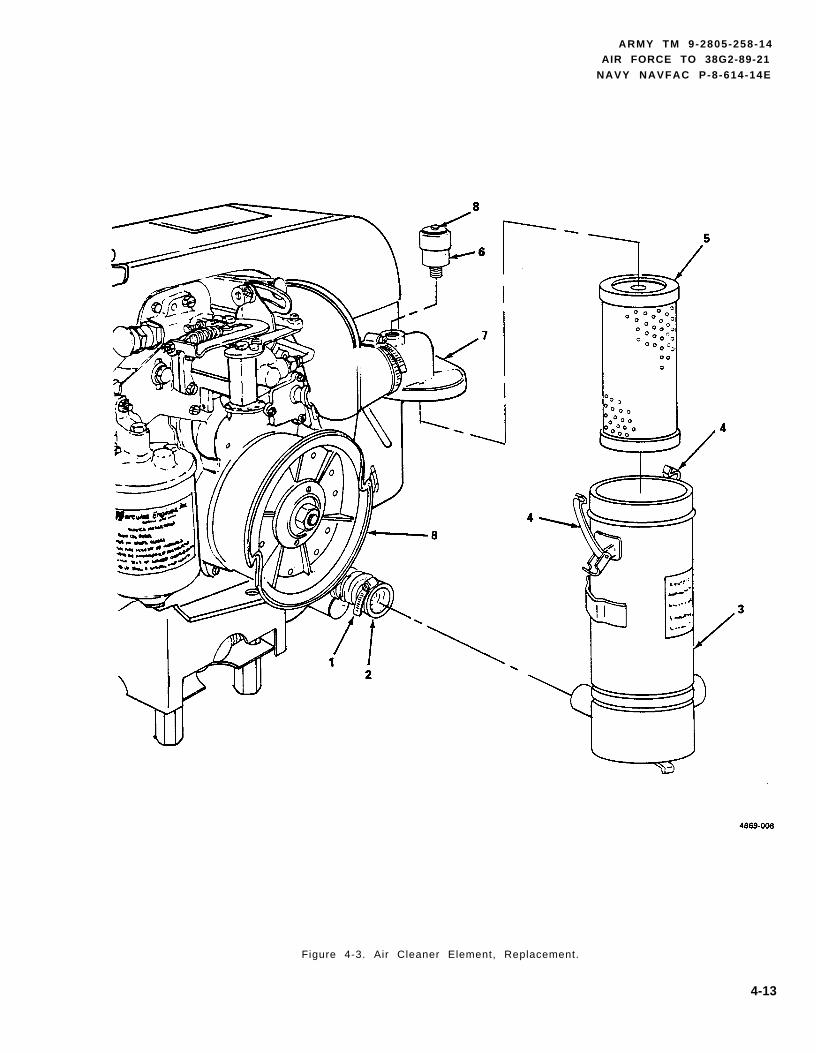
ARMY TM 9-2805-258-14AIR FORCE TO 38G2-89-21
NAVY NAVFAC P-8-614-14E
Figure 4-3. Air Cleaner Element, Replacement.
4-13
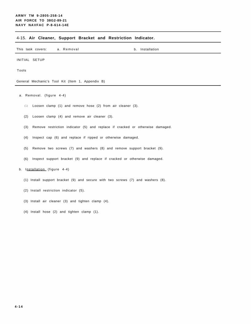
ARMY TM 9-2805-258-14AIR FORCE TO 38G2-89-21NAVY NAVFAC P-8-614-14E
4-15. Air Cleaner, Support Bracket and Restriction Indicator.
This task covers: a . R e m o v a l b. Installation
INITIAL SETUP
Tools
General Mechanic’s Tool Kit (Item 1, Appendix B)
a. Removal . ( f igure 4-4)
(1)
(2)
(3)
(4)
(5)
(6)
Loosen clamp (1) and remove hose (2) from air cleaner (3).
Loosen clamp (4) and remove air cleaner (3).
Remove restriction indicator (5) and replace if cracked or otherwise damaged.
Inspect cap (6) and replace if ripped or otherwise damaged.
Remove two screws (7) and washers (8) and remove support bracket (9).
Inspect support bracket (9) and replace if cracked or otherwise damaged.
b. Insta l la t ion ( f igure 4-4)
(1) Install support bracket (9) and secure with two screws (7) and washers (8).
(2) Install restrict ion indicator (5).
(3) Install air cleaner (3) and tighten clamp (4).
(4) Install hose (2) and tighten clamp (1).
4 - 1 4
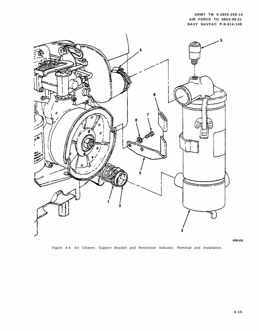
ARMY TM 9-2805-258-14AIR FORCE TO 38G2-89-21
NAVY NAVFAC P-8-614-14E
Figure 4-4. Air Cleaner, Support Bracket and Restriction Indicator, Removal and Installation.
4 - 1 5
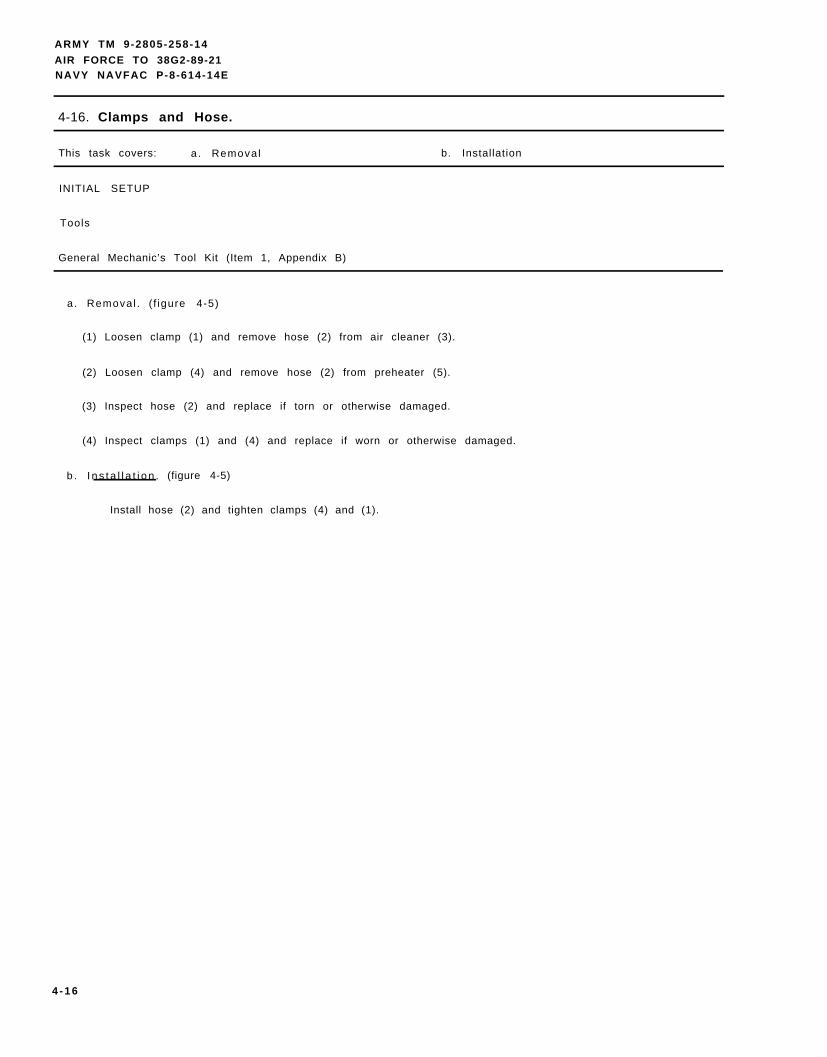
ARMY TM 9-2805-258-14
AIR FORCE TO 38G2-89-21NAVY NAVFAC P-8-614-14E
4-16. Clamps and Hose.
This task covers: a . Removal b. Installation
INITIAL SETUP
Tools
General Mechanic’s Tool Kit (Item 1, Appendix B)
a. Removal . ( f igure 4-5)
(1) Loosen clamp (1) and remove hose (2) from air cleaner (3).
(2) Loosen clamp (4) and remove hose (2) from preheater (5).
(3) Inspect hose (2) and replace if torn or otherwise damaged.
(4) Inspect clamps (1) and (4) and replace if worn or otherwise damaged.
b . I n s t a l l a t i o n . (figure 4-5)
Install hose (2) and tighten clamps (4) and (1).
4 - 1 6
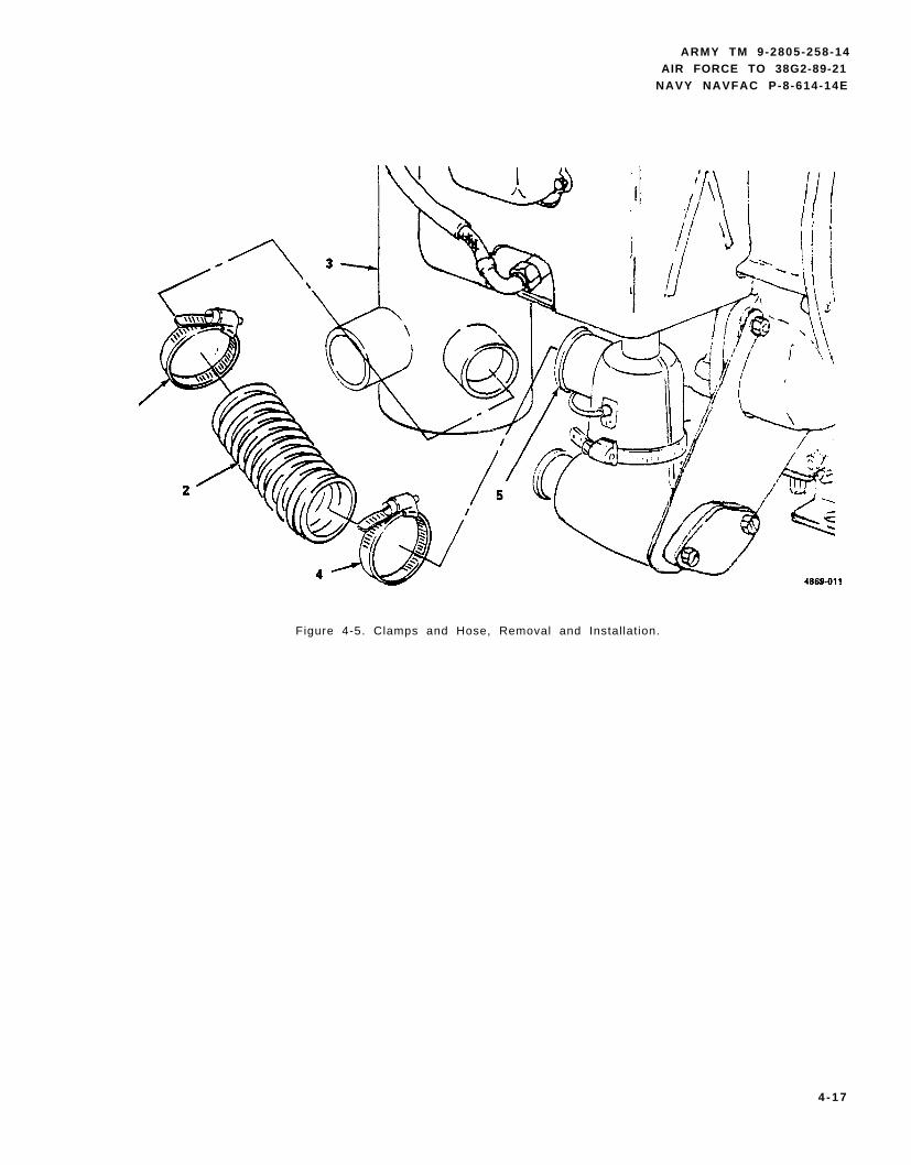
ARMY TM 9-2805-258-14AIR FORCE TO 38G2-89-21
NAVY NAVFAC P-8-614-14E
Figure 4-5. Clamps and Hose, Removal and Installation.
4 - 1 7
ARMY TM 9-2805-258-14
AIR FORCE TO 38G2-89-21NAVY NAVFAC P-8-614-14E
4-17. Air Cleaner Elbow.
This task covers: a . Removal b. Installation
INITIAL SETUP
Tools Equipment Condi t ion
General Mechanic’s Tool Kit (Item 1, Appendix B) Air cleaner removed (para. 4-15)
a. . Removal . ( f igure 4-6)
(1) Unsnap two clips (1) and remove top cover (2).
(2) Remove two screws (3) and washers (4) securing air cleaner elbow (5) to carburetor (6).
(3) Remove clamp (7) and remove air cleaner elbow (5) from air breather (8).
(4) Inspect air cleaner elbow (5) and replace if torn or otherwise damaged.
b. Insta l la t ion. (figure 4-6)
(1) Ensure mounting surfaces are clean.
(2) Slide air cleaner elbow (5) on breather tube (8) and install clamp (7).
(3) Install air cleaner elbow (5) and secure with two screws (3) and washers (4).
(4) Install top cover (2) and secure with two clips (1).
4 - 1 8
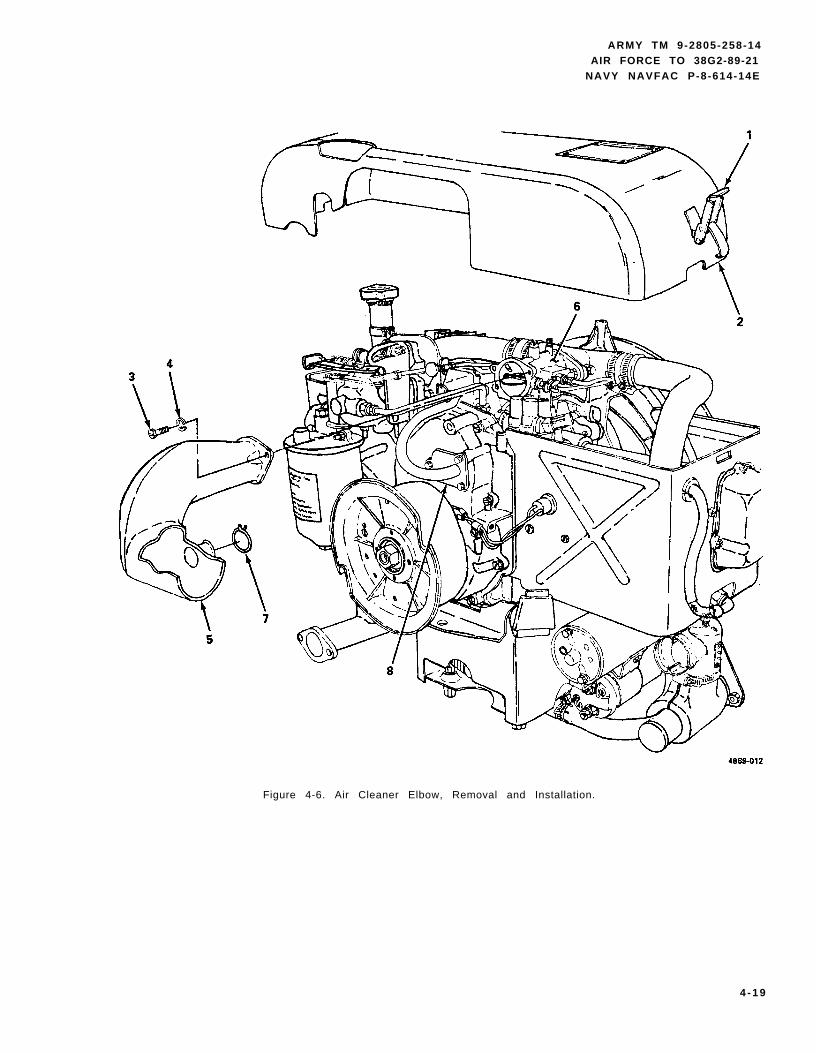
ARMY TM 9-2805-258-14AIR FORCE TO 38G2-89-21
NAVY NAVFAC P-8-614-14E
Figure 4-6. Air Cleaner Elbow, Removal and Installation.
4 - 1 9
ARMY TM 9-2805-258-14
AIR FORCE TO 38G2-89-21NAVY NAVFAC P-8-614-14E
4-18. Breather Tube.
This task covers: a . Removal b . Inspect ion c. Installation
INITIAL SETUP
Tools Equipment Condi t ion
GeneraI Mechanic’s Tool Kit (Item 1, Appendix B) Air cleaner elbow removed (para. 4-17).
Mater ia ls /Par ts
Rags, Wiping (Item 7, Appendix D)
Solvent, Drycleaning (Item 8, Appendix D)
Gasket, Air Breather Cover (NSN 2805-00-937-0943)
a. Removal . ( f igure 4-7)
Remove three screws (1) and washers (2) and remove breather tube (3) and gasket (4).
b. I n s p e c t i o n . (figure 4-7)
W A R N I N G
Drycleaning solvent PD-680 used to clean parts is potentially dangerous to personnel and
properly. Avoid repeated and prolonged skin contact. Do not use near open flame or
excessive heat. Flash point of solvent is 100°F.-138°F. (38°C.-6O°C.).
(1) Clean breather tube in drycleaning solvent, and dry thoroughly.
(2) Ensure there are no obstructions in breather tube (3).
c. /nsta//ation. (figure 4-7)
(1) Ensure gasket surfaces are clean and old gasket material is removed.
(2) Install breather tube (3) and gasket (4) and secure with three screws (1) and washers (2).
4 - 2 0
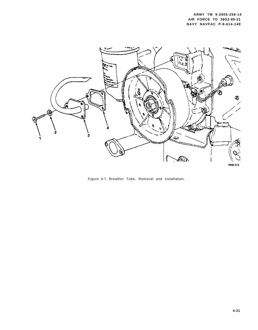
ARMY TM 9-2805-258-14AIR FORCE TO 38G2-89-21
NAVY NAVFAC P-8-614-14E
Figure 4-7. Breather Tube, Removal and Installation.
4-21
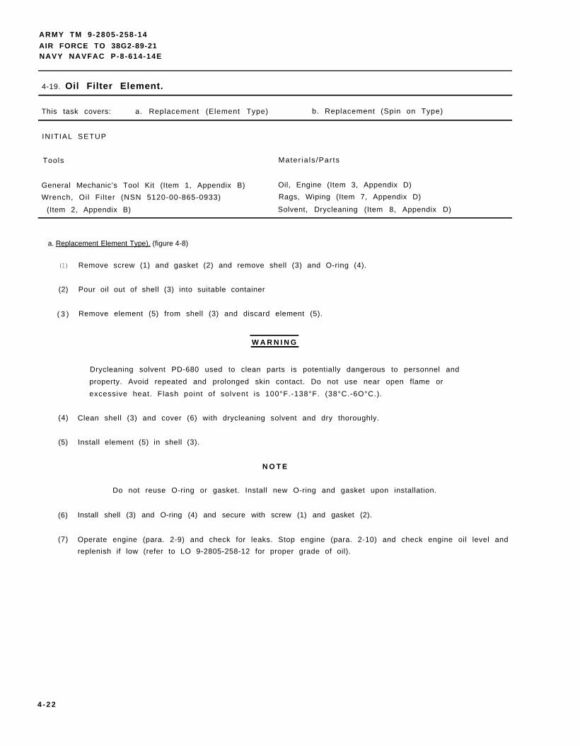
ARMY TM 9-2805-258-14
AIR FORCE TO 38G2-89-21NAVY NAVFAC P-8-614-14E
4-19. Oil Filter Element.
This task covers: a. Replacement (Element Type) b. Replacement (Spin on Type)
INITIAL SETUP
Tools Mater ia ls /Par ts
General Mechanic’s Tool Kit (Item 1, Appendix B) Oil, Engine (Item 3, Appendix D)
Wrench, Oil Filter (NSN 5120-00-865-0933) Rags, Wiping (Item 7, Appendix D)
(Item 2, Appendix B) Solvent, Drycleaning (Item 8, Appendix D)
a. Replacement Element Type). (figure 4-8)
(1)
(2)
( 3 )
(4)
(5)
(6)
(7)
4 - 2 2
Remove screw (1) and gasket (2) and remove shell (3) and O-ring (4).
Pour oil out of shell (3) into suitable container
Remove element (5) from shell (3) and discard element (5).
W A R N I N G
Drycleaning solvent PD-680 used to clean parts is potentially dangerous to personnel and
property. Avoid repeated and prolonged skin contact. Do not use near open flame or
excessive heat. Flash point of solvent is 100°F.-138°F. (38°C.-6O°C.).
Clean shell (3) and cover (6) with drycleaning solvent and dry thoroughly.
Install element (5) in shell (3).
N O T E
Do not reuse O-ring or gasket. Install new O-ring and gasket upon installation.
Install shell (3) and O-ring (4) and secure with screw (1) and gasket (2).
Operate engine (para. 2-9) and check for leaks. Stop engine (para. 2-10) and check engine oil level and
replenish if low (refer to LO 9-2805-258-12 for proper grade of oil).
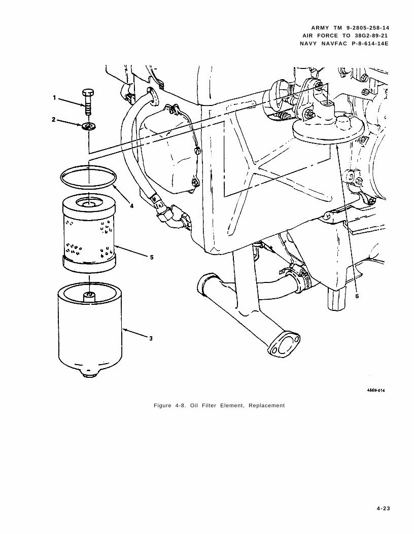
ARMY TM 9-2805-258-14AIR FORCE TO 38G2-89-21
NAVY NAVFAC P-8-614-14E
Figure 4-8. Oil Filter Element, Replacement
4 - 2 3
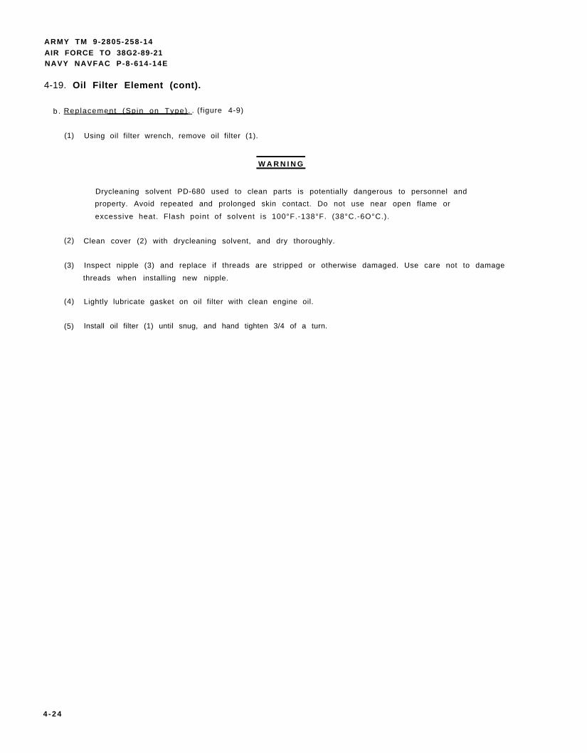
ARMY TM 9-2805-258-14AIR FORCE TO 38G2-89-21NAVY NAVFAC P-8-614-14E
4-19. Oil Filter Element (cont).
b . Replacement (Spin on Type) . . (figure 4-9)
(1)
(2)
(3)
(4)
(5)
4 - 2 4
Using oil filter wrench, remove oil filter (1).
W A R N I N G
Drycleaning solvent PD-680 used to clean parts is potentially dangerous to personnel and
property. Avoid repeated and prolonged skin contact. Do not use near open flame or
excessive heat. Flash point of solvent is 100°F.-138°F. (38°C.-6O°C.).
Clean cover (2) with drycleaning solvent, and dry thoroughly.
Inspect nipple (3) and replace if threads are stripped or otherwise damaged. Use care not to damage
threads when installing new nipple.
Lightly lubricate gasket on oil filter with clean engine oil.
Install oil filter (1) until snug, and hand tighten 3/4 of a turn.
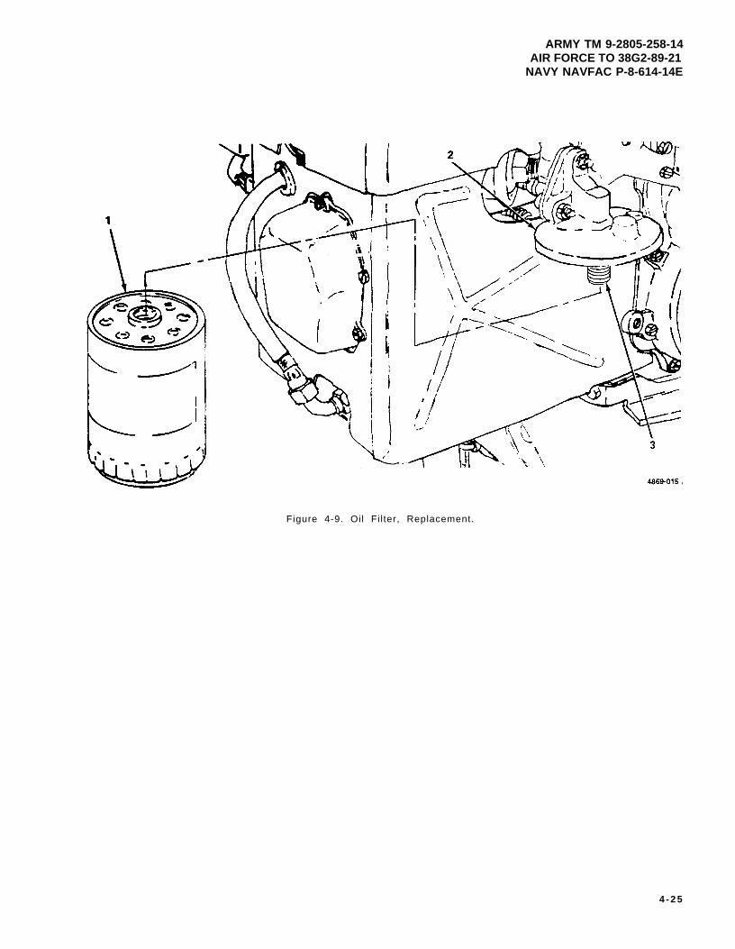
ARMY TM 9-2805-258-14AIR FORCE TO 38G2-89-21
NAVY NAVFAC P-8-614-14E
Figure 4-9. Oil Filter, Replacement.
4 - 2 5
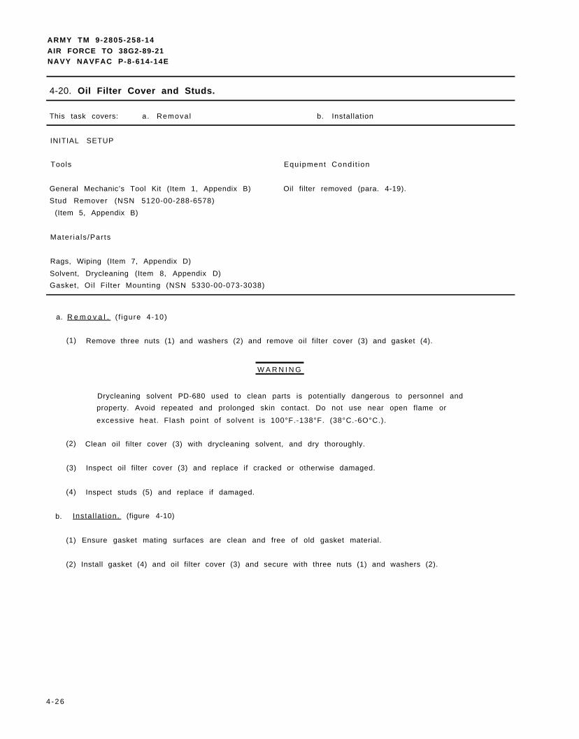
ARMY TM 9-2805-258-14AIR FORCE TO 38G2-89-21NAVY NAVFAC P-8-614-14E
4-20. Oil Filter Cover and Studs.
This task covers: a . Removal b. Installation
INITIAL SETUP
Tools Equipment Condi t ion
General Mechanic’s Tool Kit (Item 1, Appendix B) Oil filter removed (para. 4-19).
Stud Remover (NSN 5120-00-288-6578)
(Item 5, Appendix B)
Mater ia ls /Par ts
Rags, Wiping (Item 7, Appendix D)
Solvent, Drycleaning (Item 8, Appendix D)
Gasket, Oil Filter Mounting (NSN 5330-00-073-3038)
a. R e m o v a l . ( f igure 4-10)
(1)
(2)
(3)
(4)
Remove three nuts (1) and washers (2) and remove oil filter cover (3) and gasket (4).
W A R N I N G
Drycleaning solvent PD-680 used to clean parts is potentially dangerous to personnel and
property. Avoid repeated and prolonged skin contact. Do not use near open flame or
excessive heat. Flash point of solvent is 100°F.-138°F. (38°C.-6O°C.).
Clean oil filter cover (3) with drycleaning solvent, and dry thoroughly.
Inspect oil filter cover (3) and replace if cracked or otherwise damaged.
Inspect studs (5) and replace if damaged.
b. Insta l la t ion. (figure 4-10)
(1) Ensure gasket mating surfaces are clean and free of old gasket material.
(2) Install gasket (4) and oil filter cover (3) and secure with three nuts (1) and washers (2).
4 - 2 6
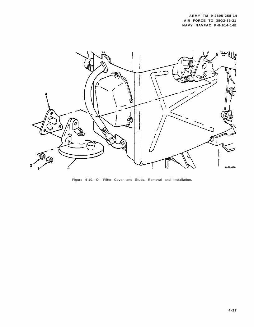
ARMY TM 9-2805-258-14AIR FORCE TO 38G2-89-21
NAVY NAVFAC P-8-614-14E
Figure 4-10. Oil Filter Cover and Studs, Removal and Installation.
4 - 2 7
ARMY TM 9-2805-258-14AIR FORCE TO 38G2-89-21NAVY NAVFAC P-8-614-14E
4-21. Top Cover, Right and Left Shrouds and Cylinder Baffles.
This task covers: a . Removal b. Installation
INITIAL SETUP
Tools
General Mechanic’s Tool Kit (Item 1, Appendix B)
Equipment Condi t ion
Air cleaner removed (para. 4-15),
a. Removal . ( f igure 4-11)
(1)
(2)
(3)
(4)
(5)
(6)
(7)
(8)
(9)
( l o )
(11)
(12)
(13)
(14)
(15)
(16)
(17)
4 - 2 8
Unsnap two clips (1) and remove top cover (2).
Unplug wiring harness connector (3) from inside of right hand shroud (4).
Remove alternator connector (5) from outside of right hand shroud (4).
Remove four screws (6) and remove connector (7) from right hand shroud (4).
Loosen connector nut (8) and remove high tension cable (9).
Remove grommet (10) and remove high tension cable (9) from right hand shroud (4).
Remove wiring harness clips (11) from right hand shroud (4).
Tag and disconnect wiring from starter (12) and automatic choke solenoid (13).
Remove four assembled screws and washers (14) and remove right hand shroud (4).
Loosen connector nut (15) and remove high tension cable (16).
Remove grommet (17) and remove high tension cable (16) from left hand shroud (18).
Remove connector (19) from outside and remove connector (20) from inside of left hand shroud (18).
Remove wiring harness clips (11) from left hand shroud (18).
Remove two assembled screws and washers (21) and remove left hand shroud (18).
Remove spring (22) and remove right hand cylinder baffle (23).
Remove spring (24) and remove left hand cylinder baffle (25).
Inspect all items and replace damaged or missing items.
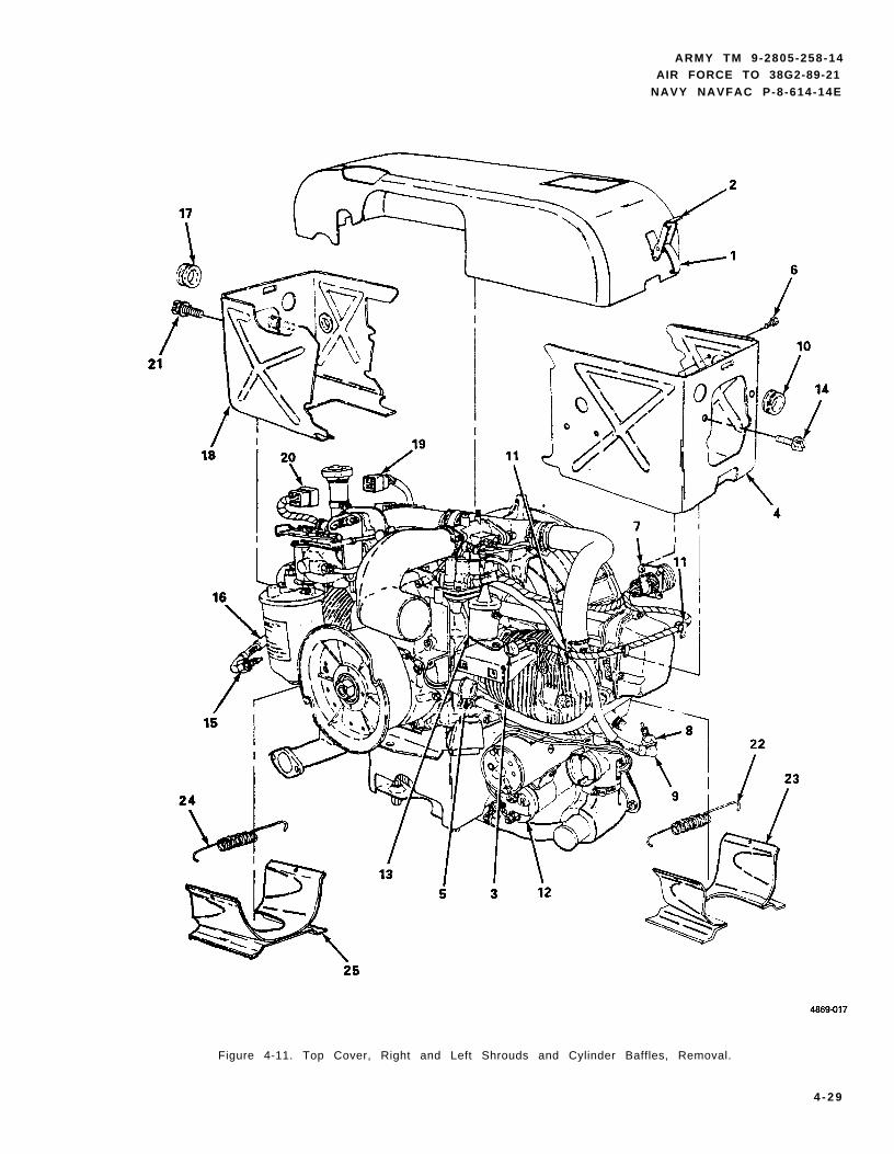
ARMY TM 9-2805-258-14AIR FORCE TO 38G2-89-21
NAVY NAVFAC P-8-614-14E
Figure 4-11. Top Cover, Right and Left Shrouds and Cylinder Baffles, Removal.
4 - 2 9
ARMY TM 9-2805-258-14AIR FORCE TO 38G2-89-21NAVY NAVFAC P-8-614-14E
4-21.
b..
Top Cover, Right and Left Shrouds and Cylinder Baffles (cont ) .
Insta l la t ion. (figure 4-12)
(1)
(2)
(3)
(4)
(5)
(6)
(7)
(8)
(9)
( 1 0 )
( 1 1 )
(12)
(13)
(14)
(15)
(16)
Install left cylinder baffle (25) and secure with spring (24).
Install right hand cylinder baffle (23) and secure with spring (22).
Install left hand shroud (18) and secure with two assembled screws and washers (21).
Install wiring harness clips (11) on left hand shroud (18).
Install connectors (19) and (20) in left hand shroud (18).
Install high tension cable (16) and grommet (17) in left hand shroud (18).
Install high tension cable (16) and tighten connector nut (15).
Install right hand shroud (4) and secure with four assembled screws and washers (14).
Install wiring harness clips (11) on right hand shroud (4).
Install high tension cable (9) and grommet (10) in right hand shroud (4).
Install high tension cable (9) and tighten connector nut (8).
Install connector (7) and secure with four screws (6).
Install alternator connector (5) from outside of right hand shroud (4).
Connect wiring harness connector (3) from inside of right hand shroud (4).
Connect wiring, as tagged to starter (12) and automatic choke solenoid (13).
Install top cover (2) and secure with two clips (1).
4 - 3 0
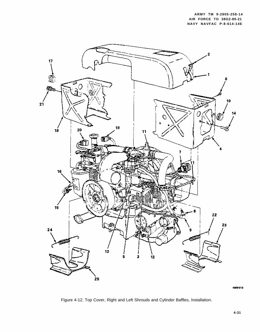
ARMY TM 9-2805-258-14AIR FORCE TO 38G2-89-21
NAVY NAVFAC P-8-614-14E
Figure 4-12. Top Cover, Right and Left Shrouds and Cylinder Baffles, Installation.
4-31
ARMY TM 9-2805-258-14AIR FORCE TO 38G2-89-21NAVY NAVFAC P-8-614-14E
4-22. Oil Pan Cover, Shroud and Baffle Plate.
This task covers: a . Removal b. Installation
INITIAL SETUP
Tools
General Mechanic’s
Mater ia ls /Par ts
Washer , Recessed:
(P/N 13214E8196)
Equipment Condi t ion
Tool Kit (Item 1, Appendix B) Top cover removed (para. 4-21).
Air cleaner removed (para. 4-15).
Exhaust Manifold
a. R e m o v a l . ( f igure 4-13)
(1)
(2)
(3)
(4)
(5)
(6)
(7)
(8)
Tag and remove lead from choke solenoid (1).
Tag and remove leads from starter solenoid (2).
Remove two nuts (3), Iockwashers (4), flat washers (5) and screws (6) and remove starter (2).
Loosen clamp (7) and remove hose (8).
N O T E
Some engines do not use seats.
Remove four nuts (9) and remove exhaust manifold (10) and seats(11).
Remove two screws (12) and washers (13) and remove baffle plate (14).
Remove four posts (15), Iockwashers (16), and flat washers (17) and remove oil pan cover (18).
Remove six screws (19) and washers (20) and remove oil pan shroud (21).
b. /nsta//ation. ( f igure 4-13)
(1)
(2)
(3)
(4)
(5)
(6)
4 - 3 2
Install oil pan shroud (21 ) and secure with six screws (19) and washers (20).
Install oil pan cover (18) and secure with four posts (15), Iockwashers(16) and flat washers (17).
Install baffle plate (14) and secure with two screws (12) and washer (13).
Install exhaust manifold (1 O) and seats(11 ) and secure with four nuts (9).
Install hose (8) and tighten clamp (7).
Install starter (2) and secure with two screws (6), flat washers (5), Iockwashers (4) and nuts (3).
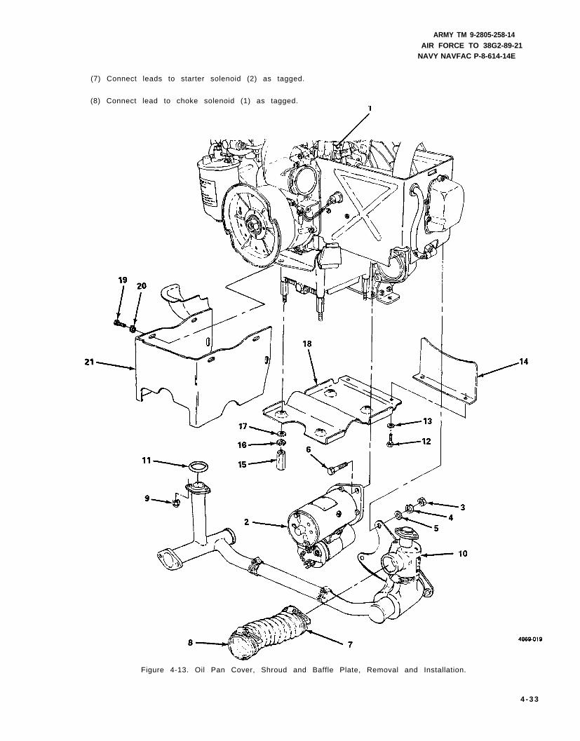
ARMY TM 9-2805-258-14AIR FORCE TO 38G2-89-21
NAVY NAVFAC P-8-614-14E
(7) Connect leads to starter solenoid (2) as tagged.
(8) Connect lead to choke solenoid (1) as tagged.
Figure 4-13. Oil Pan Cover, Shroud and Baffle Plate, Removal and Installation.
4 - 3 3
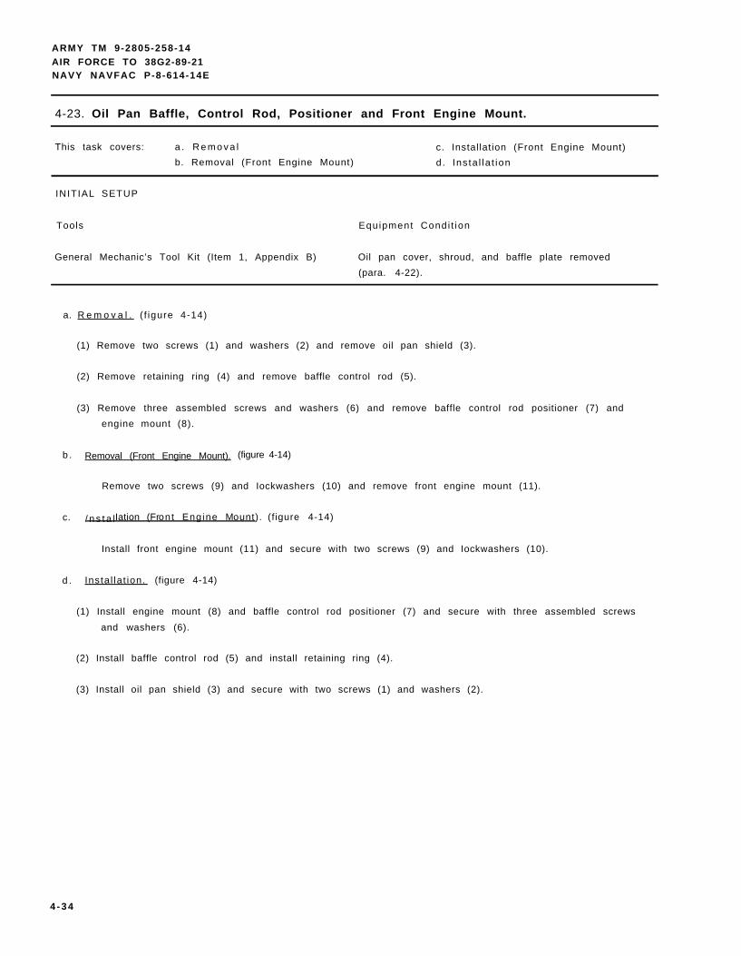
ARMY TM 9-2805-258-14AIR FORCE TO 38G2-89-21NAVY NAVFAC P-8-614-14E
4-23. Oil Pan Baffle, Control Rod, Positioner and Front Engine Mount.
This task covers: a . R e m o v a l c. Installation (Front Engine Mount)
b. Removal (Front Engine Mount) d . Ins ta l la t ion
INITIAL SETUP
Tools Equipment Condi t ion
General Mechanic’s Tool Kit (Item 1, Appendix B) Oil pan cover, shroud, and baffle plate removed
(para. 4-22).
a. R e m o v a l . ( f igure 4-14)
(1) Remove two screws (1) and washers (2) and remove oil pan shield (3).
(2) Remove retaining ring (4) and remove baffle control rod (5).
(3) Remove three assembled screws and washers (6) and remove baffle control rod positioner (7) and
engine mount (8).
b . Removal (Front Engine Mount). (figure 4-14)
Remove two screws (9) and Iockwashers (10) and remove front engine mount (11).
c. / n s t a lIation (Front Engine Mount). (figure 4-14)
Install front engine mount (11) and secure with two screws (9) and Iockwashers (10).
d . Insta l la t ion. (figure 4-14)
(1) Install engine mount (8) and baffle control rod positioner (7) and secure with three assembled screws
and washers (6).
(2) Install baffle control rod (5) and install retaining ring (4).
(3) Install oil pan shield (3) and secure with two screws (1) and washers (2).
4 - 3 4
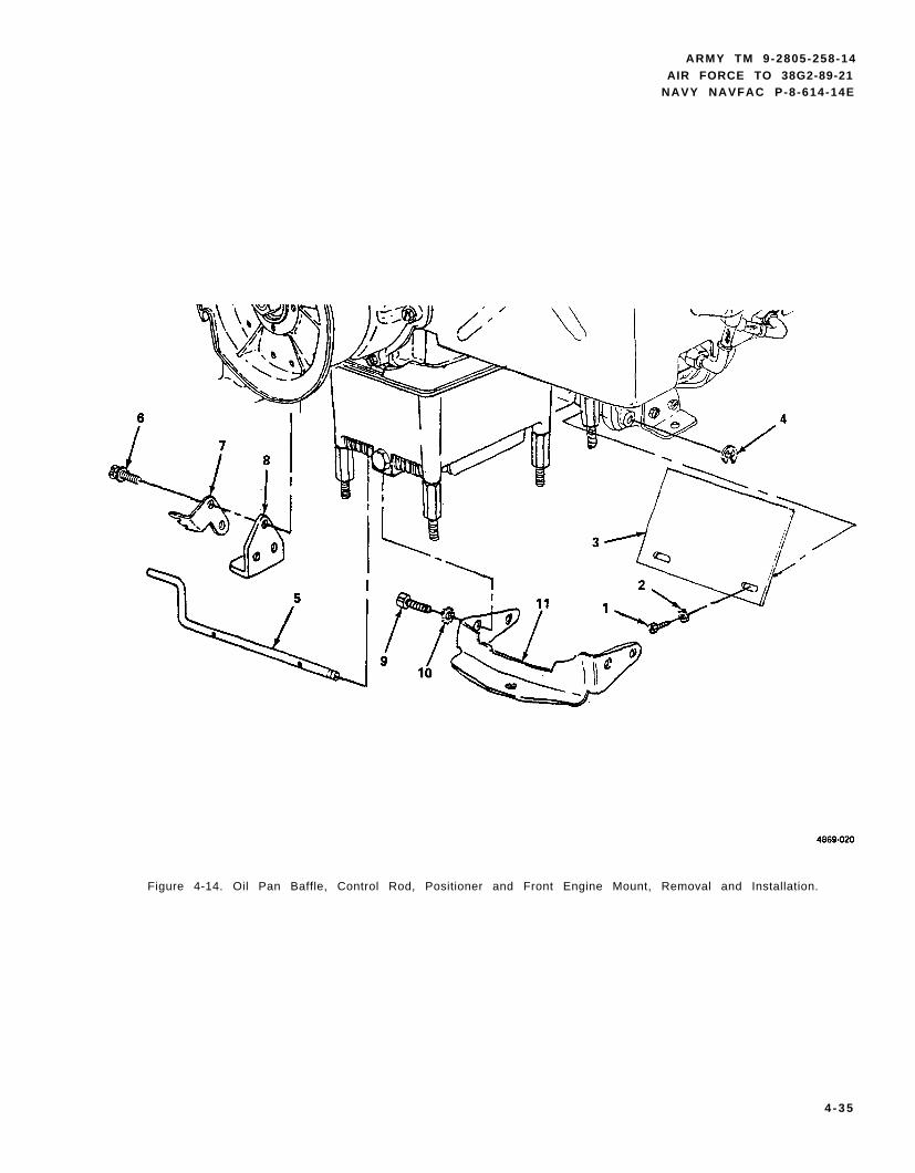
ARMY TM 9-2805-258-14AIR FORCE TO 38G2-89-21
NAVY NAVFAC P-8-614-14E
Figure 4-14. Oil Pan Baffle, Control Rod, Positioner and Front Engine Mount, Removal and Installation.
4 - 3 5
ARMY TM 9-2805-258-14AIR FORCE TO 38G2-89-21NAVY NAVFAC P-8-614-14E
4-24. Oil Lines and Fittings.
This task covers: a . R e m o v a l b. Installation
INITIAL SETUP
Tools Equipment Condi t ion
General Mechanic’s Tool Kit (Item 1, Appendix B) Top cover removed (para. 4-21).
N O T E
The removal and installation procedures are the same for both oil lines.
a. R e m o v a l . ( f i g u r e 4 - 1 5 )
(1)
(2)
(3)
(4)
(5)
Loosen connector nuts (1) and tag and remove high tension cables (2).
Loosen coupling nuts (3) and disconnect oil line (4) from “T” connector (5).
Loosen coupling nut (6) and remove oil line (4).
Inspect oil lines and replace if line is cracked or coupling nut threads are stripped.
Inspect fittings (5), (7), (8) and (9) and replace if damaged.
b. /nstallation. ( f igure 4-15)
(1) Install oil line (4) and tighten coupling nut (6).
(2) Install oil line (4) on "T" connector (5) and tighten coupling nuts (3) and coupling nut (6).
(3) Install high tension cables (2) and tighten connector nuts (1).
4 - 3 6
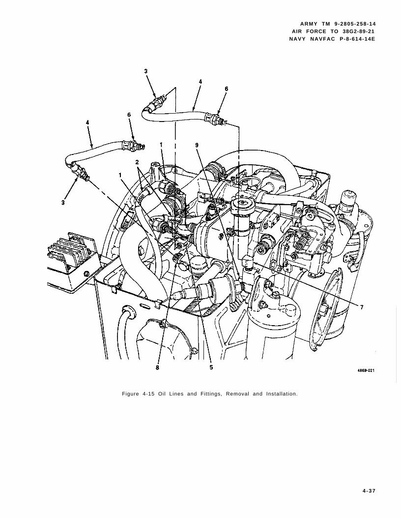
ARMY TM 9-2805-258-14AIR FORCE TO 38G2-89-21
NAVY NAVFAC P-8-614-14E
Figure 4-15 Oil Lines and Fitt ings, Removal and Installation.
4 - 3 7
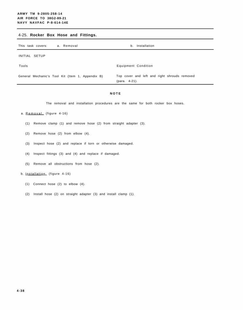
ARMY TM 9-2805-258-14AIR FORCE TO 38G2-89-21NAVY NAVFAC P-8-614-14E
4-25. Rocker Box Hose and Fittings.
This task covers: a . Removal b. Installation
INITIAL SETUP
Tools Equipment Condi t ion
General Mechanic’s Tool Kit (Item 1, Appendix B) Top cover and left and right shrouds removed
(para. 4-21).
N O T E
The removal and installation procedures are the same for both rocker box hoses.
a. R e m o v a l . ( f igure 4-16)
(1)
(2)
(3)
(4)
(5)
Remove clamp (1) and remove hose (2) from straight adapter (3).
Remove hose (2) from elbow (4).
Inspect hose (2) and replace if torn or otherwise damaged.
Inspect fittings (3) and (4) and replace if damaged.
Remove all obstructions from hose (2).
b. I n s t a l l a t i o n . ( f igure 4-16)
(1)
(2)
4 - 3 8
Connect hose (2) to elbow (4).
Install hose (2) on straight adapter (3) and install clamp (1).
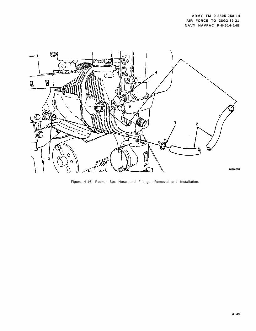
ARMY TM 9-2805-258-14AIR FORCE TO 38G2-89-21
NAVY NAVFAC P-8-614-14E
Figure 4-16. Rocker Box Hose and Fittings, Removal and Installation.
4 - 3 9
ARMY TM 9-2805-258-14AIR FORCE TO 38G2-89-21NAVY NAVFAC P-8-614-14E
4-26. Pressure Regulator Valve.
This task covers: a . Removal b. Installation
INITIAL SETUP
Tools Equipment Condi t ion
General Mechanic’s Tool Kit (Item 1, Appendix B) Top cover removed (para. 4-21).
Mater ia ls /Par ts
Rags, Wiping (Item 7, Appendix D)
Solvent, Drycleaning (Item 8, Appendix D)
a. R e m o v a l ( f igure 4-17)
(1) Remove plug (1), washer (2), spring (3), and piston (4).
W A R N I N G
Drycleaning solvent PD-680 used to clean parts is potentially dangerous to personnel and
property. Avoid repeated and prolonged skin contact. Do not use near open flame or
excessive heat. Flash point of solvent is 100°F.-138°F. (38°C.-6O°C.).
(2) Clean all items in drycleaning solvent, and dry thoroughly.
(3) Inspect all items and replace all damaged items.
b. Insta l la t ion. (figure 4-17)
Install piston (4), spring (3), washer (2) and plug (1).
4 - 4 0
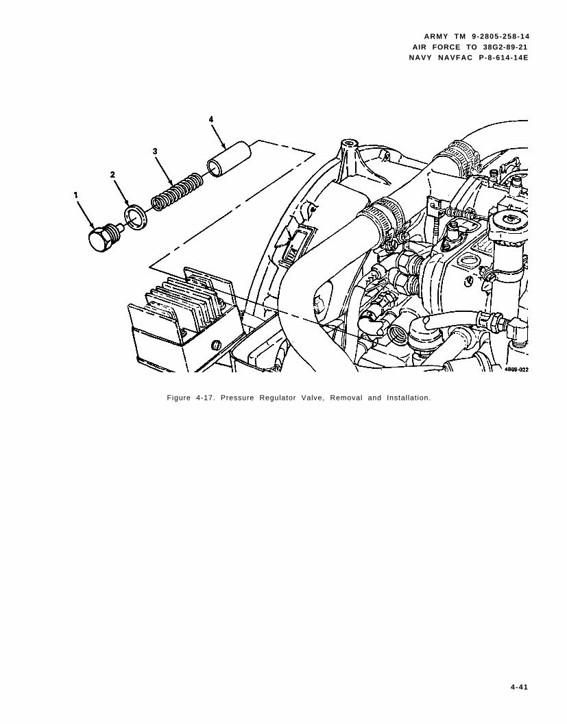
ARMY TM 9-2805-258-14AIR FORCE TO 38G2-89-21
NAVY NAVFAC P-8-614-14E
Figure 4-17. Pressure Regulator Valve, Removal and Installation.
4-41
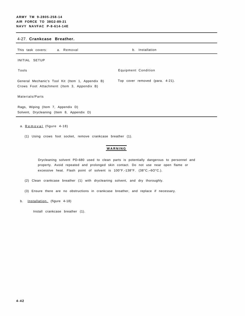
ARMY TM 9-2805-258-14AIR FORCE TO 38G2-89-21NAVY NAVFAC P-8-614-14E
4-27. Crankcase Breather.
This task covers: a . Removal b. Installation
INITIAL SETUP
Tools Equipment Condi t ion
General Mechanic’s Tool Kit (Item 1, Appendix B) Top cover removed (para. 4-21).
Crows Foot Attachment (Item 3, Appendix B)
Mater ia ls /Par ts
Rags, Wiping (Item 7, Appendix D)
Solvent, Drycleaning (Item 8, Appendix D)
a. R e m o v a l ( f igure 4-18)
(1) Using crows foot socket, remove crankcase breather (1).
W A R N I N G
Drycleaning solvent PD-680 used to clean parts is potentially dangerous to personnel and
property. Avoid repeated and prolonged skin contact. Do not use near open flame or
excessive heat. Flash point of solvent is 100°F.-138°F. (38°C.–6O°C.).
(2) Clean crankcase breather (1) with drycleaning solvent, and dry thoroughly.
(3) Ensure there are no obstructions in crankcase breather, and replace if necessary.
b. Insta l la t ion. (figure 4-18)
Install crankcase breather (1).
4 - 4 2
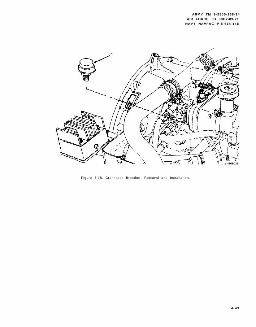
ARMY TM 9-2805-258-14AIR FORCE TO 38G2-89-21
NAVY NAVFAC P-8-614-14E
Figure 4-18. Crankcase Breather, Removal and Installation.
4 - 4 3
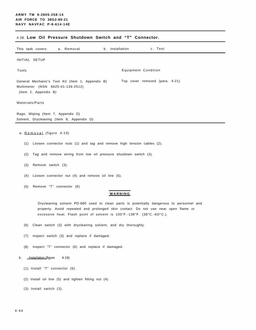
ARMY TM 9-2805-258-14AIR FORCE TO 38G2-89-21NAVY NAVFAC P-8-614-14E
4-28. Low Oil Pressure Shutdown Switch and “T” Connector.
This task covers: a . Removal b. installation c . Tes t
INITIAL SETUP
Tools Equipment Condi t ion
General Mechanic’s Tool Kit (Item 1, Appendix B) Top cover removed (para. 4-21).
Multimeter (NSN 6625-01-139-2512)
(Item 2, Appendix B)
Mater ia ls /Par ts
Rags, Wiping (Item 7, Appendix D)
Solvent, Drycleaning (Item 8, Appendix D)
a. R e m o v a l ( f igure 4-19)
(1)
(2)
(3)
(4)
(5)
(6)
(7)
(8)
Loosen connector nuts (1) and tag and remove high tension cables (2).
Tag and remove wiring from low oil pressure shutdown switch (3).
Remove switch (3).
Loosen connector nut (4) and remove oil line (5).
Remove “T” connector (6)
W A R N I N G
Drycleaning solvent PD-680 used to clean parts is potentially dangerous to personnel and
property. Avoid repeated and prolonged skin contact. Do not use near open flame or
excessive heat. Flash point of solvent is 100°F.-138°F. (38°C.-6O°C.).
Clean switch (3) with drycleaning solvent, and dry thoroughly.
inspect switch (3) and replace if damaged.
Inspect “T” connector (6) and replace if damaged.
b. /nsta//ation.(figure 4-19)
(1) Install “T” connector (6).
(2) Install oil line (5) and tighten fitting nut (4).
(3) Install switch (3).
4 - 4 4
ARMY TM 9-2805-258-14AIR FORCE TO 38G2-89-21
NAVY NAVFAC P-8-614-14E
(4) Connect leads to switch (3) as tagged.
(5) Install high tension cables (2) as tagged and tighten connector nuts(1).
c. T e s t .
(1) Check for 0 ohms between NC contact and case.
(2) Check for open circuit between NO contact and case.
(3) Replace a switch that does not meet the above requirements.
Figure 4-19. Low Oil Pressure Shutdown Switch and "‘T" Connector, Removal and Installation.
4 - 4 5
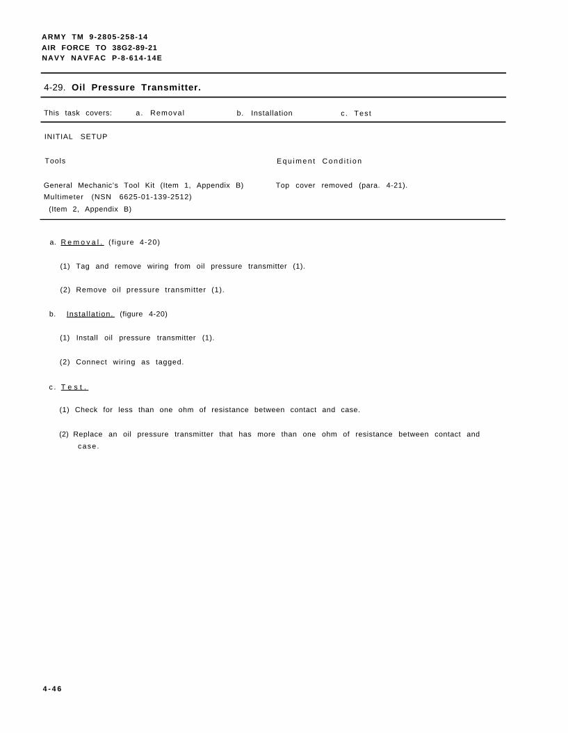
ARMY TM 9-2805-258-14AIR FORCE TO 38G2-89-21NAVY NAVFAC P-8-614-14E
4-29. Oil Pressure Transmitter.
This task covers: a . Removal b. Installation c . Tes t
INITIAL SETUP
Tools E q u i m e n t C o n d i t i o n
General Mechanic’s Tool Kit (Item 1, Appendix B) Top cover removed (para. 4-21).
Multimeter (NSN 6625-01-139-2512)
(Item 2, Appendix B)
a. R e m o v a l . ( f igure 4-20)
(1) Tag and remove wiring from oil pressure transmitter (1).
(2) Remove oil pressure transmitter (1).
b. Insta l la t ion. (figure 4-20)
(1) Install oil pressure transmitter (1).
(2) Connect wiring as tagged.
c . T e s t .
(1) Check for less than one ohm of resistance between contact and case.
(2) Replace an oil pressure transmitter that has more than one ohm of resistance between contact and
case .
4 - 4 6
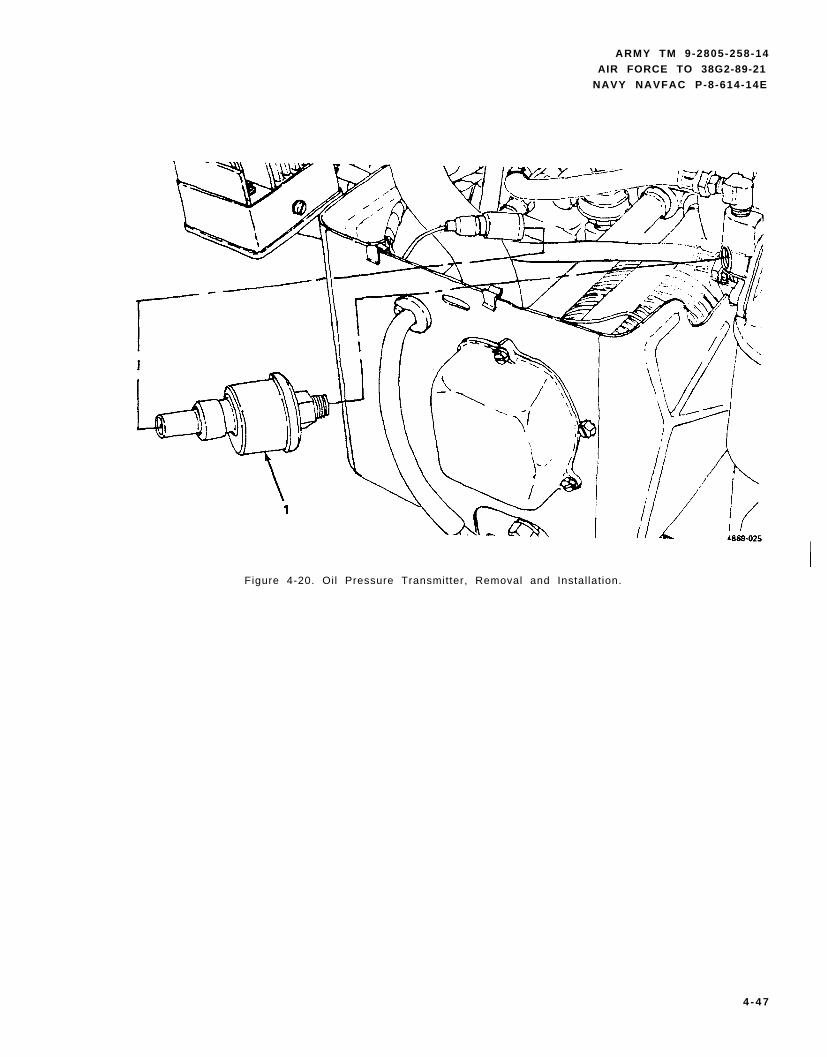
ARMY TM 9-2805-258-14AIR FORCE TO 38G2-89-21
NAVY NAVFAC P-8-614-14E
Figure 4-20. Oil Pressure Transmitter, Removal and Installation.
4 - 4 7
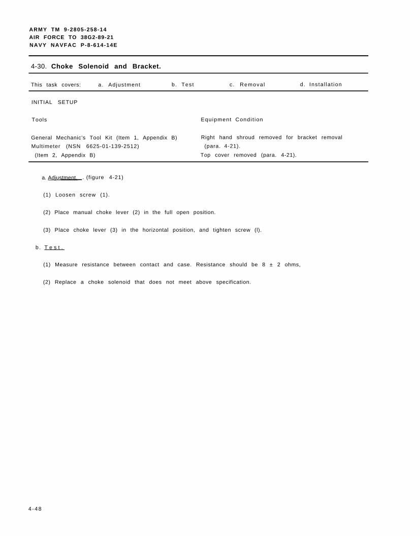
ARMY TM 9-2805-258-14AIR FORCE TO 38G2-89-21NAVY NAVFAC P-8-614-14E
4-30. Choke Solenoid and Bracket.
This task covers: a. Adjustment b . Tes t c . Remova l d . Ins ta l la t ion
INITIAL SETUP
Tools Equipment Condi t ion
General Mechanic’s Tool Kit (Item 1, Appendix B) Right hand shroud removed for bracket removal
Multimeter (NSN 6625-01-139-2512) (para. 4-21).
(Item 2, Appendix B) Top cover removed (para. 4-21).
a. Adjustment. . (figure 4-21)
(1) Loosen screw (1).
(2) Place manual choke lever (2) in the full open position.
(3) Place choke lever (3) in the horizontal position, and tighten screw (l).
b . T e s t .
(1) Measure resistance between contact and case. Resistance should be 8 ± 2 ohms,
(2) Replace a choke solenoid that does not meet above specification.
4 - 4 8
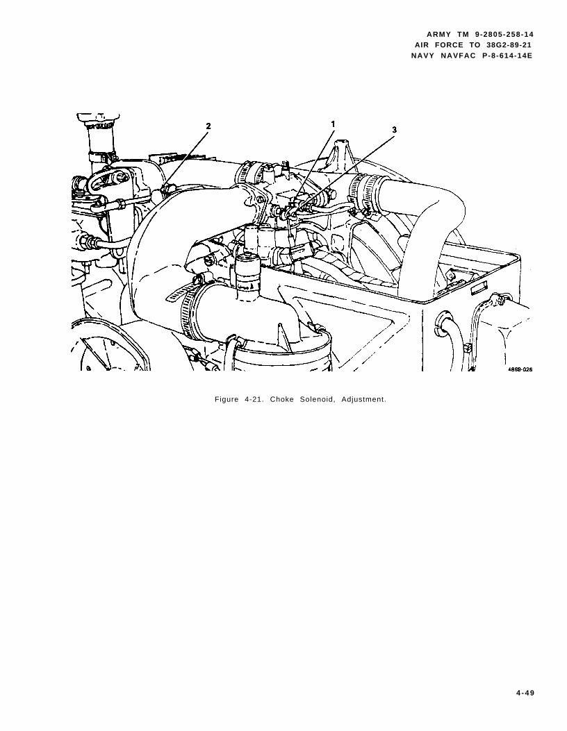
ARMY TM 9-2805-258-14AIR FORCE TO 38G2-89-21
NAVY NAVFAC P-8-614-14E
Figure 4-21. Choke Solenoid, Adjustment.
4 - 4 9
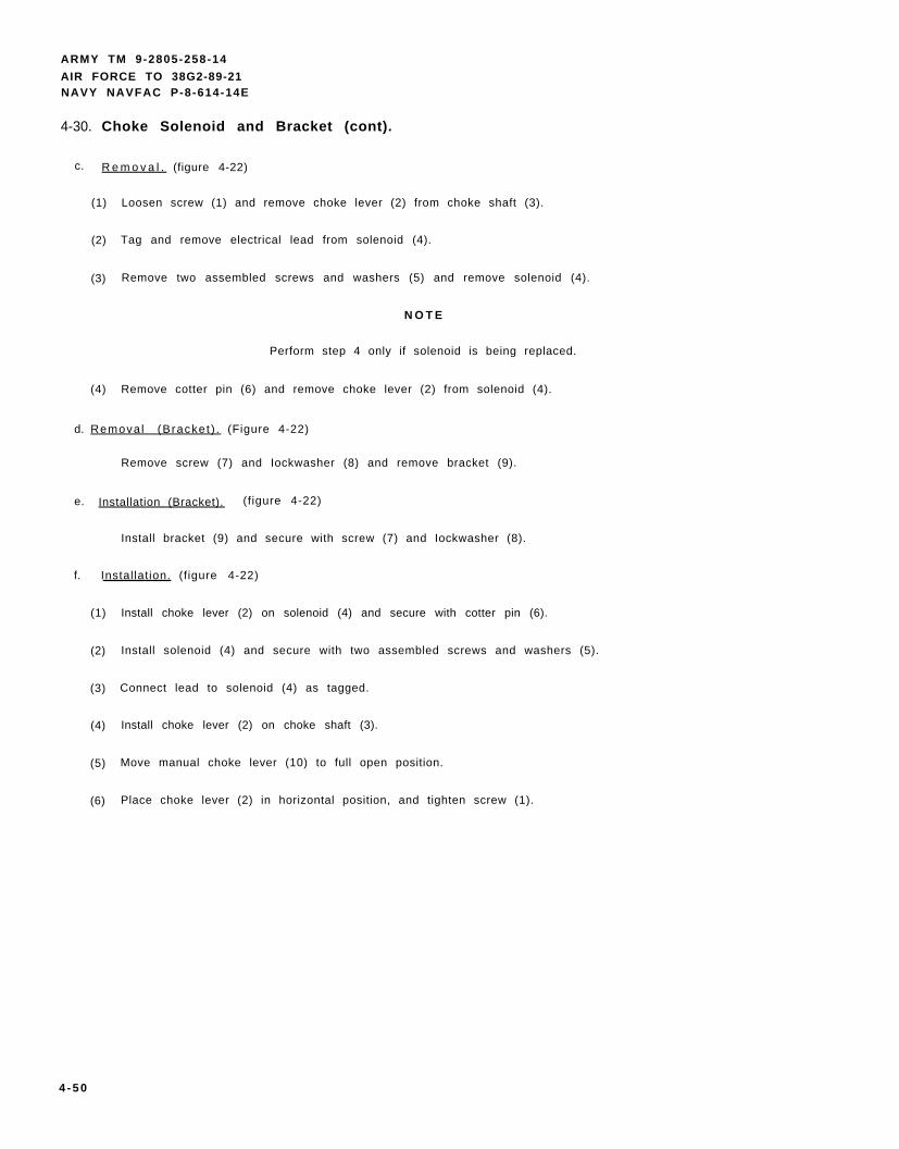
ARMY TM 9-2805-258-14
AIR FORCE TO 38G2-89-21NAVY NAVFAC P-8-614-14E
4-30.
c.
Choke Solenoid and Bracket (cont).
R e m o v a l . (figure 4-22)
(1)
(2)
(3)
(4)
Loosen screw (1) and remove choke lever (2) from choke shaft (3).
Tag and remove electrical lead from solenoid (4).
Remove two assembled screws and washers (5) and remove solenoid (4).
N O T E
Perform step 4 only if solenoid is being replaced.
Remove cotter pin (6) and remove choke lever (2) from solenoid (4).
d. Remova l (Bracket ) . (Figure 4-22)
Remove screw (7) and Iockwasher (8) and remove bracket (9).
e. Installation (Bracket). (figure 4-22)
Install bracket (9) and secure with screw (7) and Iockwasher (8).
f. Installation. (figure 4-22)
(1)
(2)
(3)
(4)
(5)
(6)
4 - 5 0
Install choke lever (2) on solenoid (4) and secure with cotter pin (6).
Install solenoid (4) and secure with two assembled screws and washers (5).
Connect lead to solenoid (4) as tagged.
Install choke lever (2) on choke shaft (3).
Move manual choke lever (10) to full open position.
Place choke lever (2) in horizontal position, and tighten screw (1).
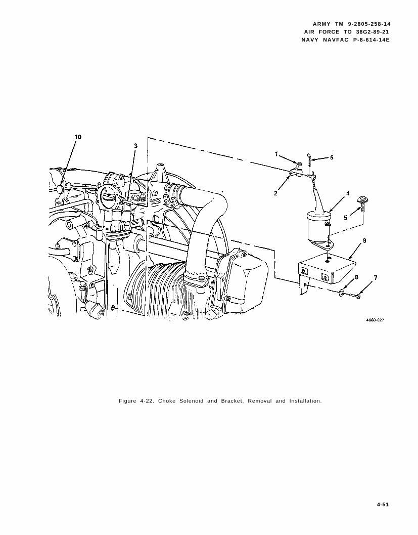
ARMY TM 9-2805-258-14AIR FORCE TO 38G2-89-21
NAVY NAVFAC P-8-614-14E
Figure 4-22. Choke Solenoid and Bracket, Removal and Installation.
4-51
ARMY TM 9-2805-258-14
AIR FORCE TO 38G2-89-21
NAVY NAVFAC P-8-614-14E
4-31. Preheater.
This task covers: a . Removal b . Tes t c. Installation
INITIAL SETUP
T o o l s Equipment Condition
General Mechanic’s Tool Kit (Item 1, Appendix B) Top cover removed (para. 4-21).
Multimeter (NSN 6625-01-139-2512)
(Item 2, Appendix B)
.
a. R e m o v a l . ( f igure 4-23)
C A U T I O N
Electrical leads are permanently attached to thermostatic switch.
(1) Tag and remove preheater lead from choke solenoid (1).
(2) Tag and remove preheater lead from starter (2).
(3) Loosen clamp (3) and remove hose (4) from preheater (5).
(4) Remove clamp (6) and remove preheater (5).
(5) Inspect both halves of preheater (5) and replace items as necessary.
b . T e s t
(1) Connect one lead of multimeter to one lead of preheater.
(2) Set multimeter for checking continuity and connect second lead of multimeter to remaining lead of
preheater.
(3) If continuity is not present, replace preheater.
c Installation.. ( f i g u r e 4 - 2 3 )
(1)
(2)
(3)
(4)
4 - 5 2
Install preheater (5) and secure with clamp (6).
Connect preheater lead to starter (2) as tagged.
Connect preheater lead to choke solenoid (1) as tagged.
Install hose (4) on preheater (5) and secure with clamp (3).
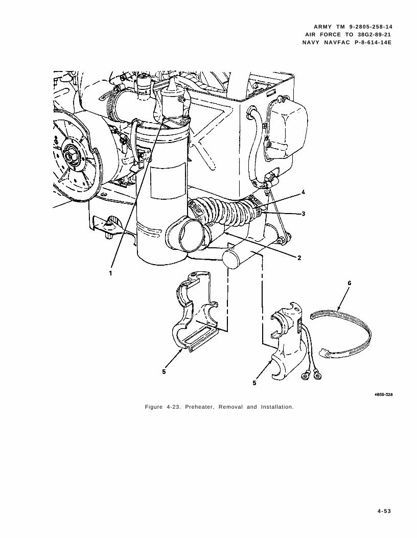
ARMY TM 9-2805-258-14AIR FORCE TO 38G2-89-21
NAVY NAVFAC P-8-614-14E
Figure 4-23. Preheater, Removal and Installation.
4 - 5 3
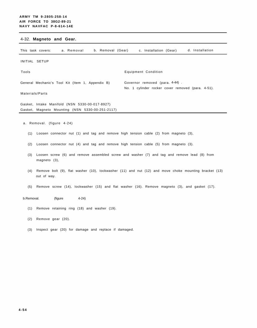
ARMY TM 9-2805-258-14AIR FORCE TO 38G2-89-21NAVY NAVFAC P-8-614-14E
4-32. Magneto and Gear.
This task covers: a . R e m o v a l b. Removal (Gear) c. Installation (Gear) d . Ins ta l la t ion
INITIAL SETUP
Tools
General Mechanic’s Tool Kit (Item 1, Appendix B)
Equipment Condi t ion
Governor removed (para. 4-44) .
No. 1 cylinder rocker cover removed (para. 4-51).
Mater ia ls /Par ts
Gasket, Intake Manifold (NSN 5330-00-017-8927)
Gasket, Magneto Mounting (NSN 5330-00-251-2117)
a. Removal . ( f igure 4-24)
(1)
(2)
(3)
Loosen connector nut (1) and tag and remove high tension cable (2) from magneto (3),
Loosen connector nut (4) and tag and remove high tension cable (5) from magneto (3).
Loosen screw (6) and remove assembled screw and washer (7) and tag and remove lead (8) from
magneto (3),
(4) Remove bolt (9), flat washer (10), Iockwasher (11) and nut (12) and move choke mounting bracket (13)
out of way.
(5)
b.Removal. (figure 4-24)
(1)
(2)
(3)
Remove screw (14), Iockwasher (15) and flat washer (16). Remove magneto (3), and gasket (17).
Remove retaining ring (18) and washer (19).
Remove gear (20).
Inspect gear (20) for damage and replace if damaged.
4 - 5 4
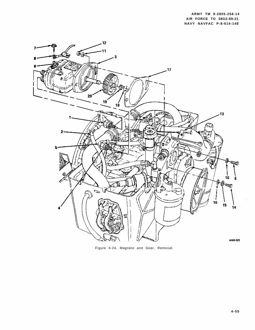
ARMY TM 9-2805-258-14AIR FORCE TO 38G2-89-21
NAVY NAVFAC P-8-614-14E
Figure 4-24. Magneto and Gear, Removal.
4 - 5 5
ARMY TM 9-2805-258-14
AIR FORCE TO 38G2-89-21NAVY NAVFAC P-8-614-14E
4-32. Magneto and Gear (cont).
c. Installation (Gear). (figure 4-25)
(1) Install gear (20) on magneto (3).
(2) Install washer (19) and secure with retaining ring (18).
d. Installation.. (figure 4-25)
(1)
(2)
(3)
(4)
(5)
(6)
(7)
(8)
4 - 5 6
Rotate starter rope pulley (21) until both rockers (22) open and close, and stop when timing mark on
camshaft gear (23) is present.
Install magneto (3) and gasket (17) and position magneto gear (20) so that timing mark on magneto gear
(20) alines with camshaft gear (23) timing mark.
Secure magneto (3) with screw (14), Iockwasher (15) and flat washer (16).
Position manual choke bracket (13) and secure with bolt (9), washer (10), Iockwasher (11) and nut (12).
Install lead (8) as tagged and secure with assembled screw and washer (7).
Install clip under screw (6) and tighten screw (6).
Install high tension cable (5) as tagged, and tighten connector nut (4).
Install high tension cable (2) as tagged, and tighten connector nut (1).
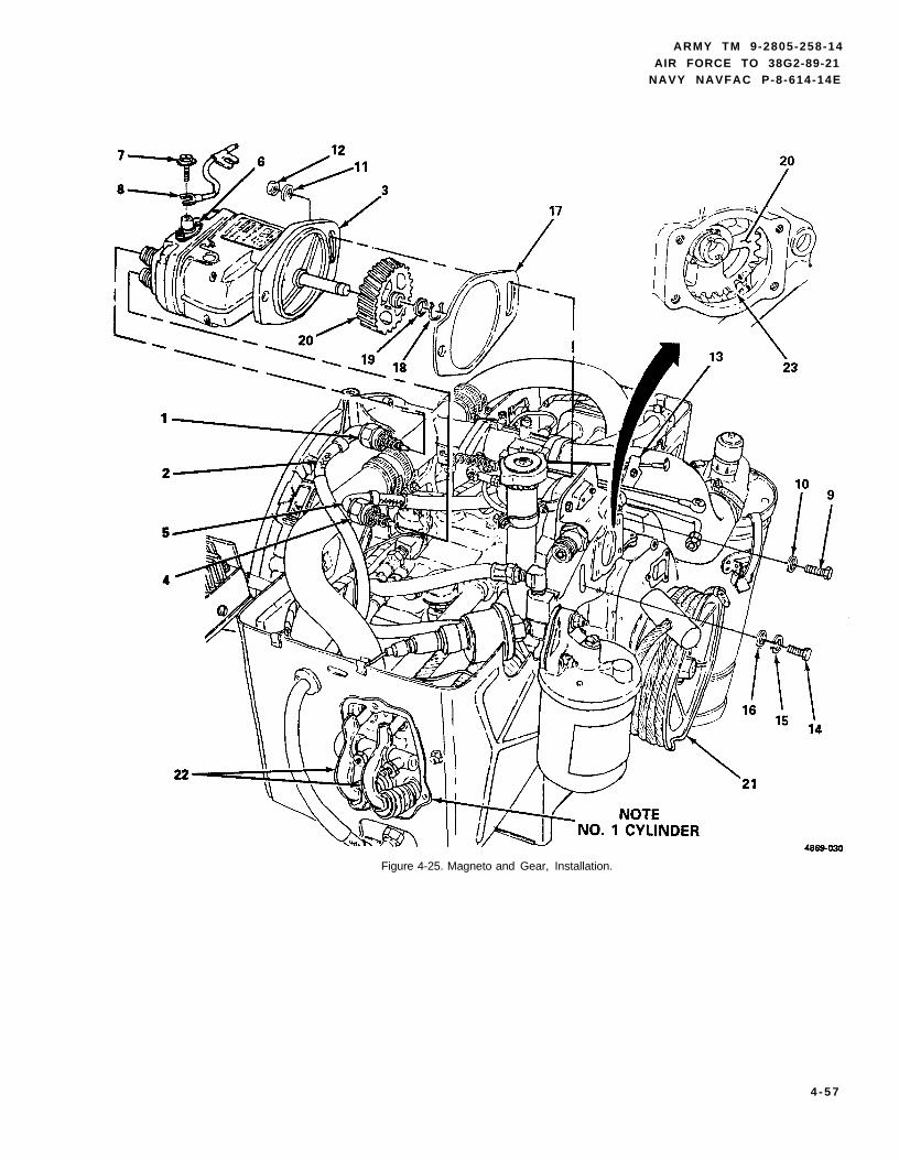
ARMY TM 9-2805-258-14AIR FORCE TO 38G2-89-21
NAVY NAVFAC P-8-614-14E
Figure 4-25. Magneto and Gear, Installation.
4 - 5 7
ARMY TM 9-2805-258-14
AIR FORCE TO 38G2-89-21NAVY NAVFAC P-8-614-14E
4-33. Ignition Timing.
This task covers: Adjustment
INITIAL SETUP
Tools Equipment Condi t ion
General Mechanic’s Tool Kit (Item 1, Appendix B) Governor adjusted (para. 4-44).
Light, Timing (NSN 4910-00-937-5724) Top cover removed (para. 4-21).
(Item 2, Appendix B)
Adjustment. (f igure 4-26)
(1)
(2)
(3)
(4)
(5)
(6)
(7)
(8)
Loosen connector nut (1) and disconnect No. 1 cylinder high tension cable (2).
Connect timing light (3) to high tension cable (2) and spark plug (4).
Loosen bolt (5) and nut (6).
Start engine (para. 2-9) and run at full governed speed.
Point timing light (3) at timing hole (7) and adjust magneto (8) until timing mark on flywheel (9) alines
with pointer (10) and tighten bolt (5) and nut (6).
Stop engine (para. 2-10).
Disconnect timing light (3) from high tension cable (2) and spark plug (4).
Install high tension cable (2) on spark plug (4) and tighten connector nut (1).
4 - 5 8
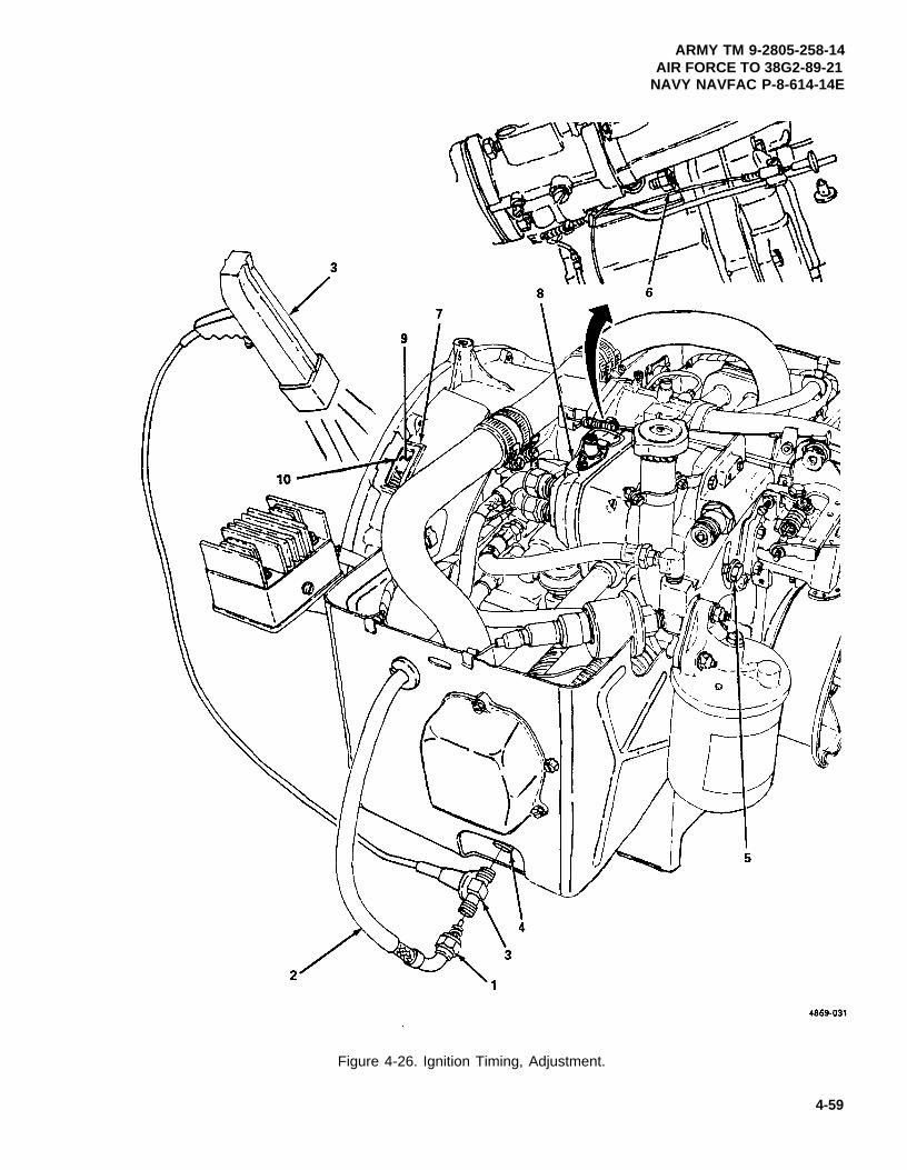
ARMY TM 9-2805-258-14AIR FORCE TO 38G2-89-21
NAVY NAVFAC P-8-614-14E
Figure 4-26. Ignition Timing, Adjustment.
4-59
ARMY TM 9-2805-258-14AIR FORCE TO 38G2-89-21NAVY NAVFAC P-8-614-14E
4-34. Magneto Contacts.
This task covers: a. Adjustment b . Removal c. Installation
INITIAL SETUP
Tools Equipment Condi t ion
General Mechanic’s Tool Kit (Item 1, Appendix B) Top cover removed (para. 4-21).
Mater ia ls /Par ts
Oil, Engine (Item 3, Appendix D)
a. A d j u s t m e n t. (figure 4-27)
(1)
(2)
(3)
(4)
(5)
(6)
(7)
(8)
(9)
(l0)
Loosen connector nut (1) and tag and remove high tension cable (2).
Loosen connector nut (3) and tag and remove high tension cable (4).
Remove four assembled screws and washers (5) and move magneto cover (6) out of way.
Rotate starter rope pulley (7) until cam follower (8) is on highest point of cam (9).
Loosen screw (10) and adjust gap to 0.015 in. (0.038 cm).
Tighten screw (10) and recheck gap. Repeat step 5 if gap is incorrect.
Lubricate cam wick (11) sparingly with clean engine oil.
Install magneto cover (6) and secure with four assembled screws and washers (5).
Install high tension cable (4) as tagged and tighten connector nut (3).
Install high tension cable (2) as tagged and tighten connector nut (1).
4 - 6 0
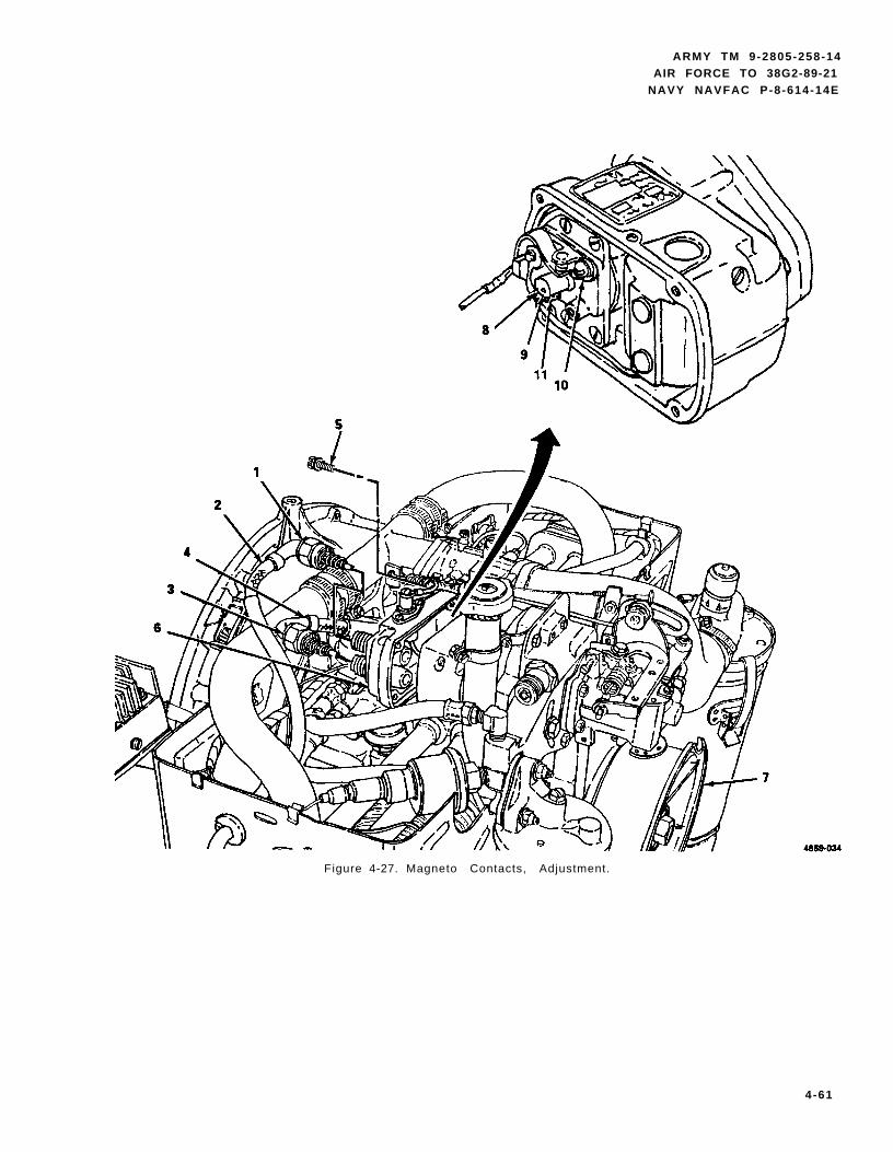
ARMY TM 9-2805-258-14AIR FORCE TO 38G2-89-21
NAVY NAVFAC P-8-614-14E
Figure 4-27. Magneto Contacts, Adjustment.
4-61
ARMY TM 9-2805-258-14AIR FORCE TO 38G2-89-21NAVY NAVFAC P-8-614-14E
4-34. Magneto Contacts (cont).
b. Removal. (figure 4-28)
(1)
(2)
(3)
(4)
(5)
(6)
Loosen connector nut (1) and tag and remove high tension cable (2).
Loosen connector nut (3) and tag and remove high tension cable (4).
Remove four assembled screws and washers (5) and move magneto cover (6) out of way.
Remove two assembled screws and washers (7) and remove contacts (8) from magneto housing (9).
Remove screw (10) and washer (11) and remove condenser lead (12) and coil lead (13).
Inspect contacts and replace if excessively burnt or pitted.
c . Insta l la t ion. ( f igure 4-28)
(1)
(2)
(3)
(4)
(5)
(6)
(7)
(8)
(9)
4 - 6 2
Install condenser lead (12) and coil lead (13) and secure with screw (10) and washer (11).
N O T E
Cam wick bracket mounts under lower screw.
Do not fully tighten upper mounting screw at this time.
Install contacts (9) and cam wick (14) and secure with two assembled screws and washers (7).
Rotate starter rope pulley (15) until cam follower (16) is on highest point of cam (17).
Adjust gap to 0.015 in. (0.038 cm) and tighten screw (7).
Check gap and repeat step 4 as needed.
Lubricate cam wick (14) sparingly with clean engine oil.
Install magneto cover (6) and secure with four assembled screws and washers (5).
Install high tension cable (4) as tagged and tighten connector nut (3).
Install high tension cable (2) as tagged and tighten connector nut (1).
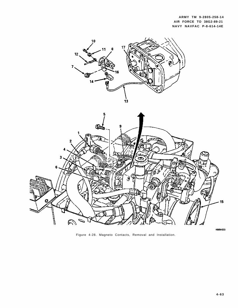
ARMY TM 9-2805-258-14AIR FORCE TO 38G2-89-21
NAVY NAVFAC P-8-614-14E
Figure 4-28. Magneto Contacts, Removal and Installation.
4 - 6 3
ARMY TM 9-2805-258-14AIR FORCE TO 38G2-89-21NAVY NAVFAC P-8-614-14E
4-35. Condenser.
This task covers: a . R e m o v a l b. Installation
INITIAL SETUP
Tools Equipment Condi t ion
General Mechanic’s Tool Kit (Item 1, Appendix B) Top cover removed (para. 4-21).
Mater ia ls /Par ts
Gasket, Condenser (P/N 01-011-679)
a. R e m o v a l . ( f igure 4-29)
(1)
(2)
(3)
(4)
(5)
(6)
(7)
(8)
Loosen connector nut (1) and tag and remove high tension cable (2).
Loosen connector nut (3) and tag and remove high tension cable (4).
Remove assembled screw and washer (5).
Loosen assembled screw and washer (6) and tag and remove lead (7) from condenser (8).
Remove four assembled screws and washers (9) and move magneto cover (10) out of way.
Remove assembled screw and washer (11) and flat washer (12) and tag and remove condenser lead
(13) and coil lead (14) from magneto contacts (15).
Remove two assembled screws and washers (6) and remove condenser (8) and gasket (16).
Inspect gasket (16) and replace if worn or otherwise damaged.
b. Installation. ( f i g u r e 4 - 2 9 )
(1)
(2)
(3)
(4)
(5)
(6)
4 - 6 4
Install condenser (8) and gasket (16) and secure with one assembled screw and washer (6).
Install condenser lead (13) and coil lead (14) and secure with assembled screw and washer (11) and flat
washer (12).
Install magneto cover (10) and secure with four assembled screws and washers (9).
Install lead (7) on condenser (8) and secure with assembled screw and washer (5).
Secure lead (7) clip with assembled screw and washer (6).
Install high tension cable (4) as tagged and tighten connector nut (3).
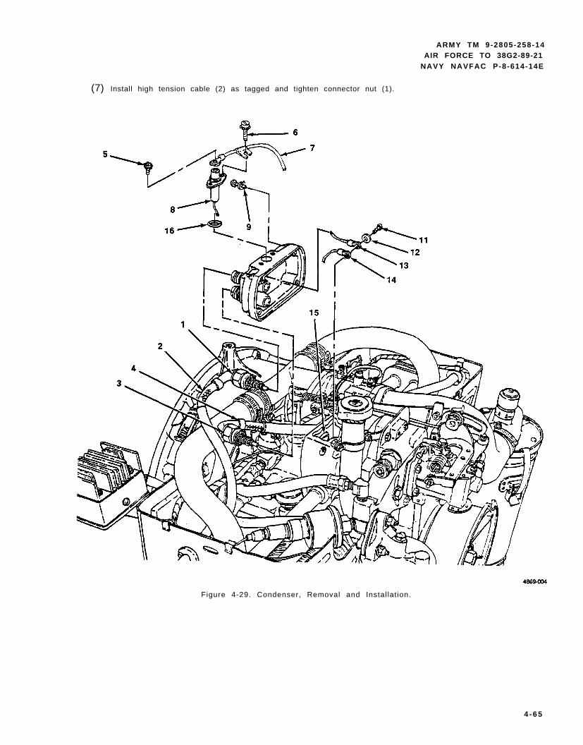
ARMY TM 9-2805-258-14AIR FORCE TO 38G2-89-21
NAVY NAVFAC P-8-614-14E
(7) Install high tension cable (2) as tagged and tighten connector nut (1).
Figure 4-29. Condenser, Removal and Installation.
4 - 6 5
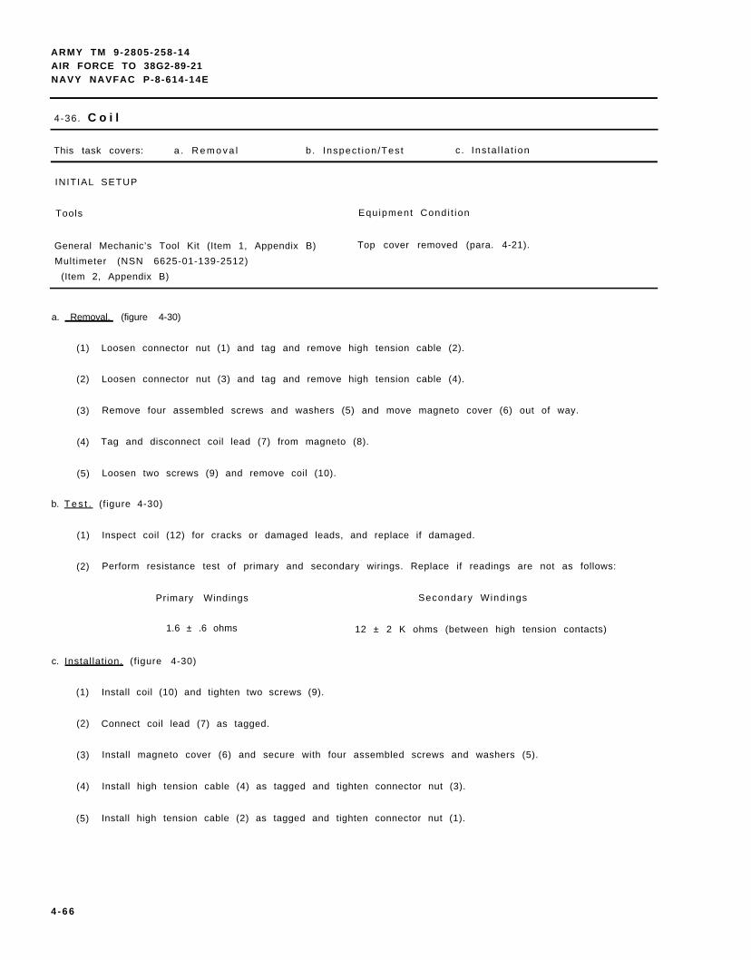
ARMY TM 9-2805-258-14AIR FORCE TO 38G2-89-21NAVY NAVFAC P-8-614-14E
4-36. C o i l
This task covers: a . R e m o v a l b . Inspect ion /Test c . Ins ta l la t ion
INITIAL SETUP
Tools Equipment Condi t ion
General Mechanic’s Tool Kit (Item 1, Appendix B) Top cover removed (para. 4-21).
Multimeter (NSN 6625-01-139-2512)
(Item 2, Appendix B)
a. Removal. (figure 4-30)
(1)
(2)
(3)
(4)
(5)
b. T e s t .
(1)
(2)
Loosen connector nut (1) and tag and remove high tension cable (2).
Loosen connector nut (3) and tag and remove high tension cable (4).
Remove four assembled screws and washers (5) and move magneto cover (6) out of way.
Tag and disconnect coil lead (7) from magneto (8).
Loosen two screws (9) and remove coil (10).
(figure 4-30)
Inspect coil (12) for cracks or damaged leads, and replace if damaged.
Perform resistance test of primary and secondary wirings. Replace if readings are not as follows:
Primary Windings Secondary Windings
1.6 ± .6 ohms 12 ± 2 K ohms (between high tension contacts)
c. Installation. (figure 4-30)
(1)
(2)
(3)
(4)
(5)
4 - 6 6
Install coil (10) and tighten two screws (9).
Connect coil lead (7) as tagged.
Install magneto cover (6) and secure with four assembled screws and washers (5).
Install high tension cable (4) as tagged and tighten connector nut (3).
Install high tension cable (2) as tagged and tighten connector nut (1).
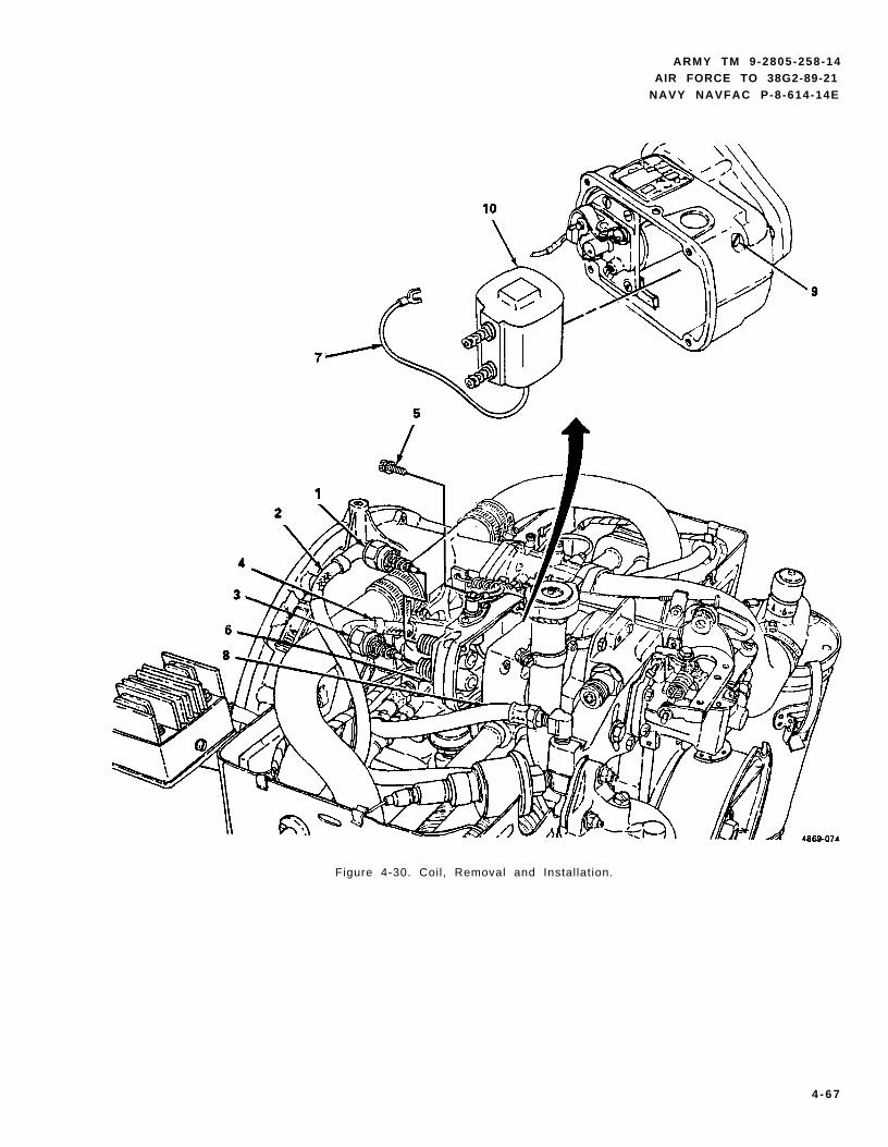
ARMY TM 9-2805-258-14AIR FORCE TO 38G2-89-21
NAVY NAVFAC P-8-614-14E
Figure 4-30. Coil, Removal and Installation.
4 - 6 7
ARMY TM 9-2805-258-14AIR FORCE TO 38G2-89-21NAVY NAVFAC P-8-614-14E
4-37. High Tension Cables.
This task covers: a . R e m o v a l b . Tes t c. Installation
INITIAL SETUP
Tools Equipment Condi t ion
General Mechanic’s Tool Kit (Item 1, Appendix B) Top cover removed (para. 4-21).
Multimeter (NSN 6625-01-139-2512)
(Item 2, Appendix B)
N O T E
The removal and installation procedures are the same for both high tension cables.
a. R e m o v a l . ( f igure 4-31)
(1) Loosen connector nut (1) and tag and remove high tension cable (2).
(2) Loosen connector nut (3) and remove high tension cable (2).
(3) Remove grommet (4) and remove high tension cable (2) from left hand shroud (5).
b . T e s t .
(1)
(2)
(3)
Perform continuity test between spring ends on high tension cable. If continuity is not present, replace
high tension cable.
Perform continuity test between metal ends of hign tension cable, if continuity is not present, replace
hign tension cable.
Perform continuity test between metal end of hign tension cable and spring end. If continuity is present,
replace high tension cable.
c. Installaiton. (f igure 4-31)
(1) Install grommet (4) on high tension cable (2) and install in left hand shroud (5).
(2) Install high tension cable (2) and tighten connector nut (3).
(3) Install high tension cable (2) as tagged and tighten connector nut (1).
4 - 6 8
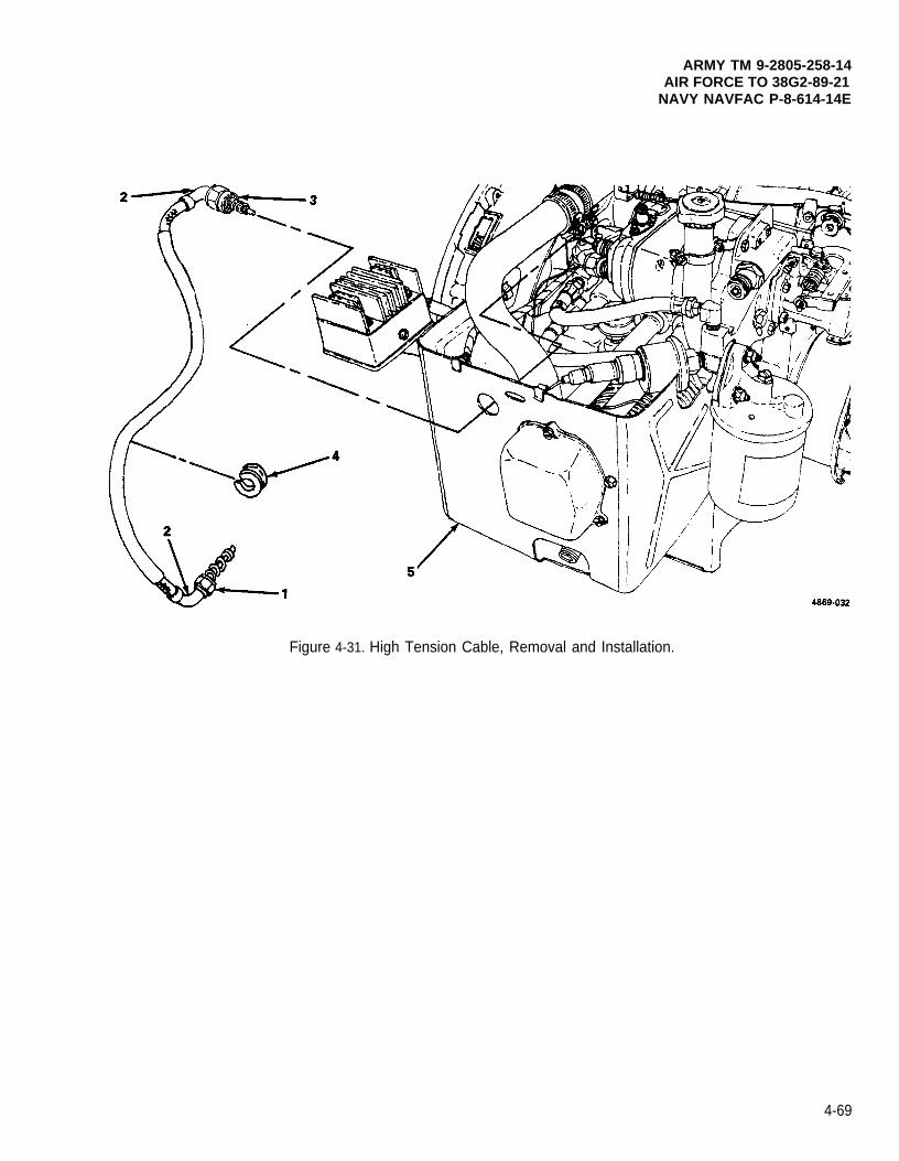
ARMY TM 9-2805-258-14AIR FORCE TO 38G2-89-21
NAVY NAVFAC P-8-614-14E
Figure 4-31. High Tension Cable, Removal and Installation.
4-69
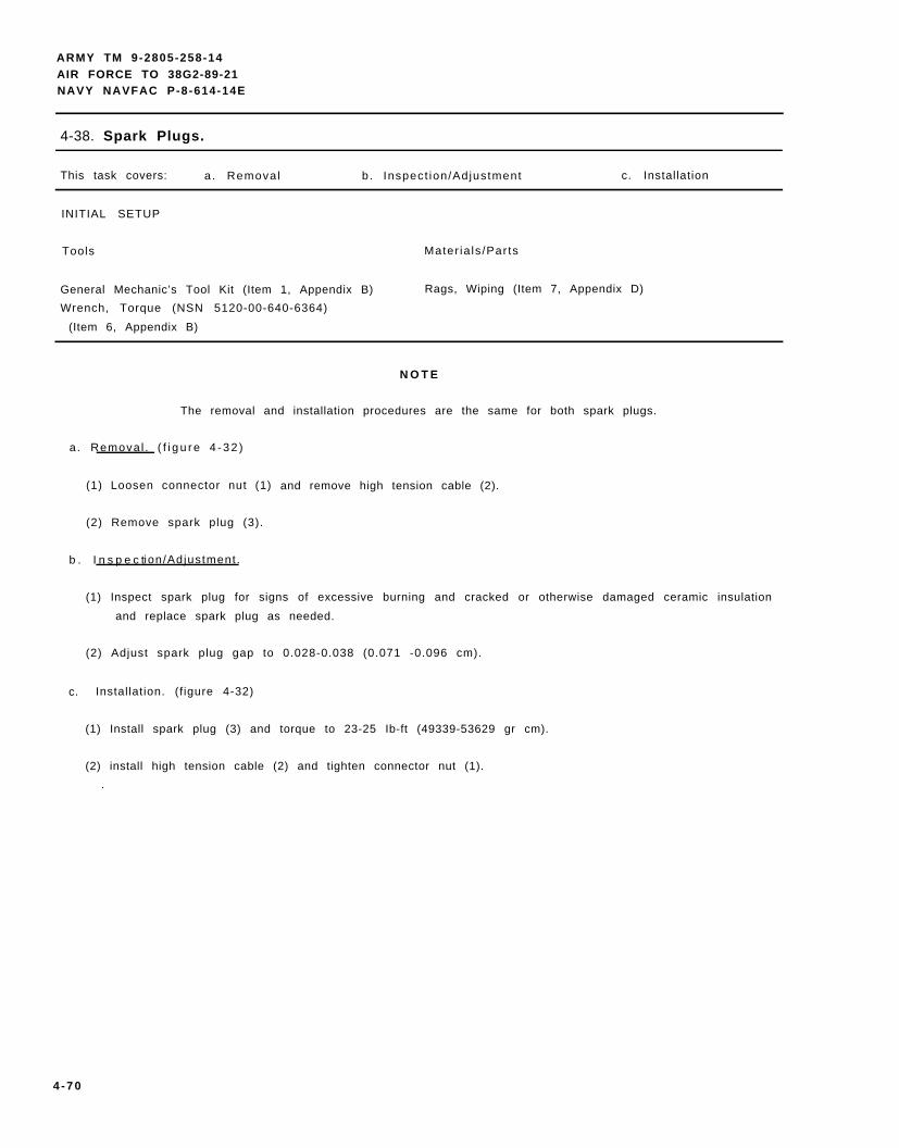
ARMY TM 9-2805-258-14AIR FORCE TO 38G2-89-21NAVY NAVFAC P-8-614-14E
4-38. Spark Plugs.
This task covers: a . Removal b. Inspect ion/Adjustment c. Installation
INITIAL SETUP
Tools Mater ia ls /Par ts
General Mechanic’s Tool Kit (Item 1, Appendix B) Rags, Wiping (Item 7, Appendix D)
Wrench, Torque (NSN 5120-00-640-6364)
(Item 6, Appendix B)
N O T E
The removal and installation procedures are the same for both spark plugs.
a. Removal . ( f i g u r e 4 - 3 2 )
(1) Loosen connector nut (1)
(2) Remove spark plug (3).
b . I n s p e c tion/Adjustment .
and remove high tension cable (2).
(1) Inspect spark plug for signs of excessive burning and cracked or otherwise damaged ceramic insulation
and replace spark plug as needed.
(2) Adjust spark plug gap to 0.028-0.038 (0.071 -0.096 cm).
c. Installation. (f igure 4-32)
(1) Install spark plug (3) and torque to 23-25 Ib-ft (49339-53629 gr cm).
(2) install high tension cable (2) and tighten connector nut (1).
.
4 - 7 0
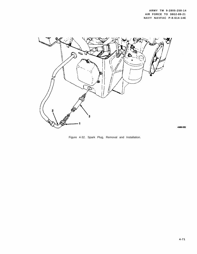
Figure 4-32. Spark Plug, Removal and Installation.
ARMY TM 9-2805-258-14AIR FORCE TO 38G2-89-21
NAVY NAVFAC P-8-614-14E
4-71
ARMY TM 9-2805-258-14
AIR FORCE TO 38G2-89-21NAVY NAVFAC P-8-614-14E
4-39. Starter.
This task covers: a . R e m o v a l b. Installation
INITIAL SETUP
Tools Equipment Condi t ion
General Mechanic’s Tool Kit (Item 1, Appendix B) Air cleaner removed (para. 4-15).
a. R e m o v a l . ( f igure 4-33)
(1) Tag and remove wiring from starter (1).
(2) Remove two bolts (2), flat washers (3), Iockwashers (4) and nuts (5) and remove starter (1).
b. Insta l la t ion. (figure 4-33)
(1)
(2)
Install starter (1) and secure with two bolts (2), flat washers (3), Iockwashers (4) and nuts (5).
Connect wiring to starter (1) as tagged.
4 - 7 2
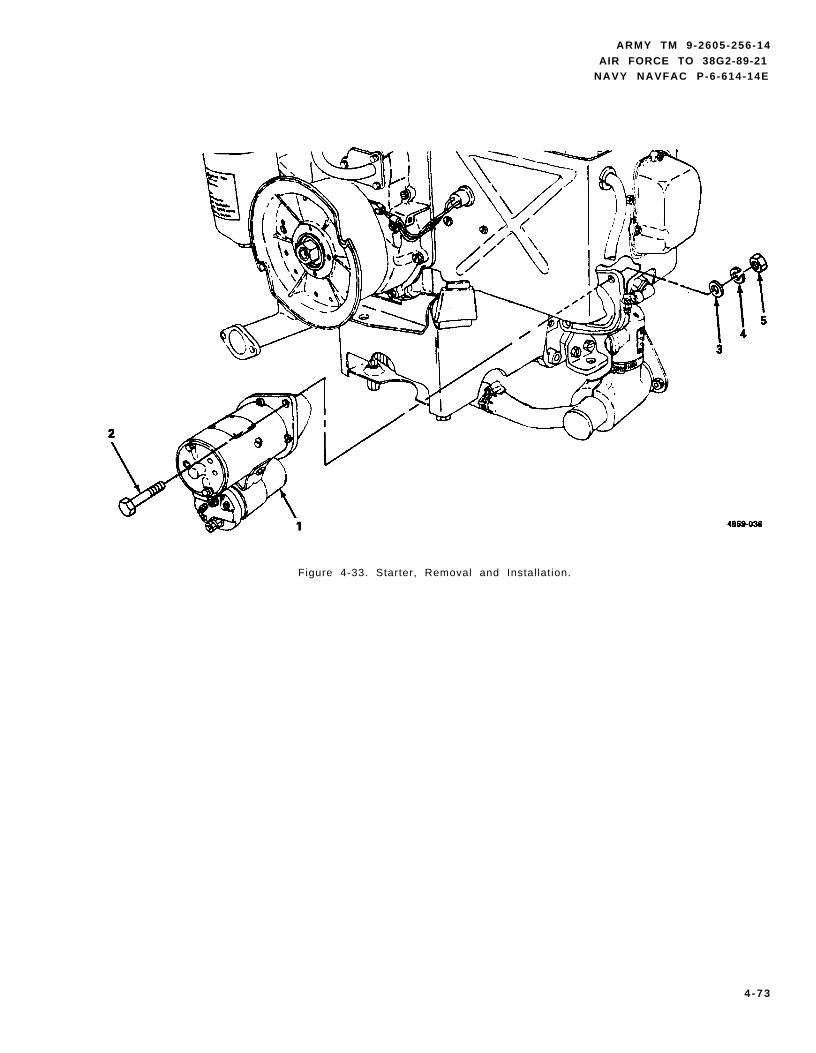
ARMY TM 9-2605-256-14AIR FORCE TO 38G2-89-21
NAVY NAVFAC P-6-614-14E
Figure 4-33. Starter, Removal and Installation.
4 - 7 3
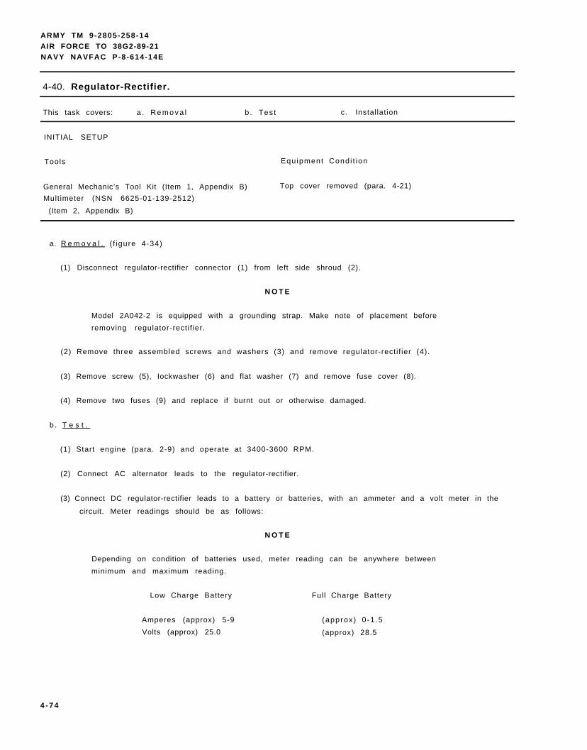
ARMY TM 9-2805-258-14AIR FORCE TO 38G2-89-21NAVY NAVFAC P-8-614-14E
4-40. Regulator-Rectifier.
This task covers: a . R e m o v a l b . Tes t c. Installation
INITIAL SETUP
Tools Equipment Condi t ion
General Mechanic’s Tool Kit (Item 1, Appendix B) Top cover removed (para. 4-21)
Multimeter (NSN 6625-01-139-2512)
(Item 2, Appendix B)
a. R e m o v a l . ( f igure 4-34)
(1) Disconnect regulator-rectifier connector (1) from left side shroud (2).
N O T E
Model 2A042-2 is equipped with a grounding strap. Make note of placement before
removing regulator-rectif ier.
(2) Remove three assembled screws and washers (3) and remove regulator-rectif ier (4).
(3) Remove screw (5), Iockwasher (6) and flat washer (7) and remove fuse cover (8).
(4) Remove two fuses (9) and replace if burnt out or otherwise damaged.
b . T e s t .
(1) Start engine (para. 2-9) and operate at 3400-3600 RPM.
(2) Connect AC alternator leads to the regulator-rectifier.
(3) Connect DC regulator-rectifier leads to a battery or batteries, with an ammeter and a volt meter in the
circuit. Meter readings should be as follows:
N O T E
Depending on condition of batteries used, meter reading can be anywhere between
minimum and maximum reading.
Low Charge Battery Full Charge Battery
Amperes (approx) 5-9 (approx) 0-1 .5
Volts (approx) 25.0 (approx) 28.5
4 - 7 4
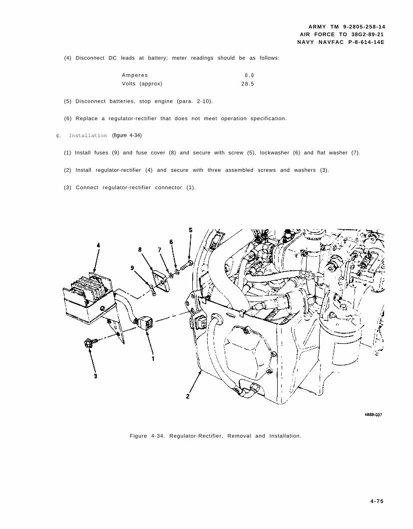
ARMY TM 9-2805-258-14AIR FORCE TO 38G2-89-21
NAVY NAVFAC P-8-614-14E
(4) Disconnect DC leads at battery; meter readings should be as follows:
A m p e r e s 0 . 0
Volts (approx) 2 8 . 5
(5) Disconnect batteries, stop engine (para. 2-10).
(6) Replace a regulator-rectif ier that does not meet operation specif ication.
c. Installation (figure 4-34)
(1) Install fuses (9) and fuse cover (8) and secure with screw (5), Iockwasher (6) and flat washer (7).
(2) Install regulator-rectifier (4) and secure with three assembled screws and washers (3).
(3) Connect regulator-rectif ier connector (1).
Figure 4-34. Regulator-Rectif ier, Removal and Installation.
4 - 7 5
ARMY TM 9-2805-258-14AIR FORCE TO 38G2-89-21NAVY NAVFAC P-8-614-14E
4-41. Governor/Carburetor Control.
This task covers: a . R e m o v a l b. Installation
INITIAL SETUP
Tools
General Mechanic’s Tool Kit (Item 1, Appendix B)
a. R e m o v a l . ( f igure 4-35)
Remove two assembled screws and washers (1) and remove governor/carburetor control (2)..
b. Insta l la t ion. (figure 4-35)
Install governor/carburetor control (2) and secure with two assembled screws and washers (1).
4 - 7 6
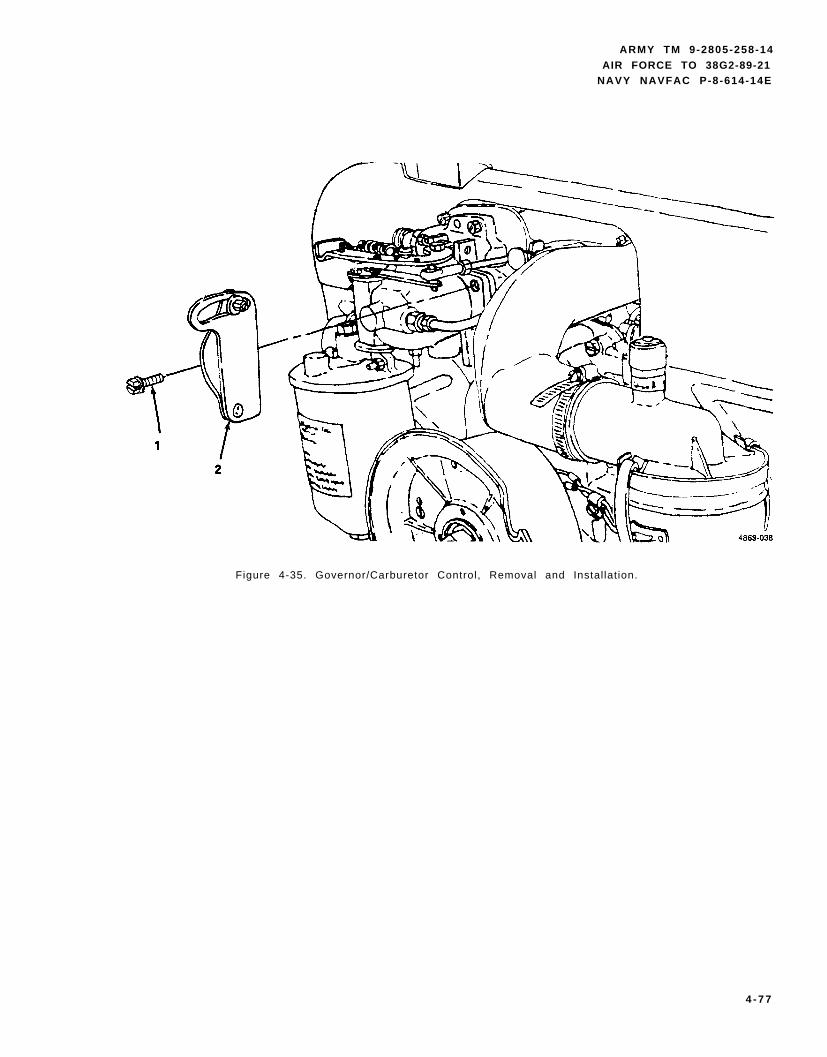
ARMY TM 9-2805-258-14AIR FORCE TO 38G2-89-21
NAVY NAVFAC P-8-614-14E
Figure 4-35. Governor/Carburetor Control, Removal and Installation.
4 - 7 7
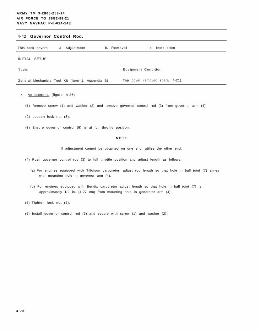
ARMY TM 9-2805-258-14
AIR FORCE TO 38G2-89-21NAVY NAVFAC P-8-614-14E
4-42. Governor Control Rod.
This task covers: a. Adjustment b . Removal c. Installation
INITIAL SETUP
Tools Equipment Condi t ion
General Mechanic’s Tool Kit (Item 1, Appendix B) Top cover removed (para. 4-21).
a. Adjus tment . (figure 4-36)
(1) Remove screw (1) and washer (2) and remove governor control rod (3) from governor arm (4).
(2) Loosen lock nut (5).
(3) Ensure governor control (6) is at full throttle position.
N O T E
If adjustment cannot be obtained on one end, utilize the other end.
(4) Push governor control rod (3) to full throttle position and adjust length as follows:
(a) For engines equipped with Tillotson carburetor, adjust rod length so that hole in ball joint (7) alines
with mounting hole in governor arm (4).
(b) For engines equipped with Bendix carburetor adjust length so that hole in ball joint (7) is
approximately 1/2 in. (1.27 cm) from mounting hole in generator arm (4).
(5) Tighten lock nut (5).
(6) Install governor control rod (3) and secure with screw (1) and washer (2).
4 - 7 8
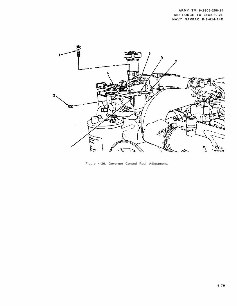
ARMY TM 9-2805-258-14AIR FORCE TO 38G2-89-21
NAVY NAVFAC P-8-614-14E
Figure 4-36. Governor Control Rod, Adjustment.
4 - 7 9
ARMY TM 9-2805-258-14
AIR FORCE TO 38G2-89-21NAVY NAVFAC P-8-614-14E
4-42. Governor Control Rod (Cont).
b. Removal . ( f igure 4-37)
(1) Remove screw (1) and washer (2) and remove governor control rod (3) from governor arm (4).
(2) Remove screw (5) and washer (6) and remove governor control rod (3) from carburetor.
(3) Inspect governor control rod throttle rod (7) and ball joints (8), replace all items that are worn, bent, or
otherwise damaged.
c. Insta l la t ion. (figure 4-37)
(1) Install governor control rod (3) and secure with screw (5) and washer (6).
(2) Adjust governor control rod. (See para. a.)
(3) Install governor control rod (3) and secure with screw (1) and washer (2).
4 - 8 0
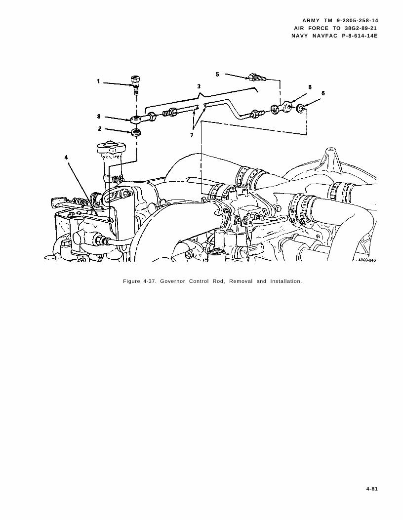
ARMY TM 9-2805-258-14AIR FORCE TO 38G2-89-21
NAVY NAVFAC P-8-614-14E
Figure 4-37. Governor Control Rod, Removal and Installation.
4-81
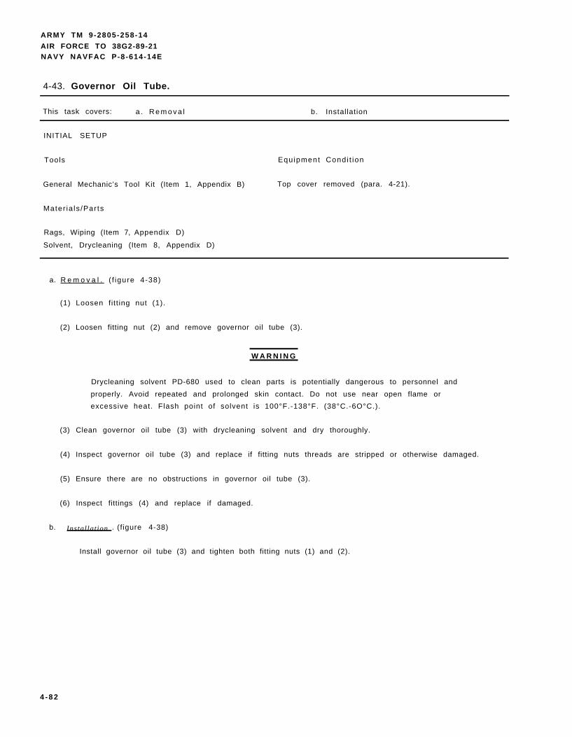
ARMY TM 9-2805-258-14
AIR FORCE TO 38G2-89-21NAVY NAVFAC P-8-614-14E
4-43. Governor Oil Tube.
This task covers: a . R e m o v a l b. Installation
INITIAL SETUP
Tools Equipment Condi t ion
General Mechanic’s Tool Kit (Item 1, Appendix B) Top cover removed (para. 4-21).
Mater ia ls /Par ts
Rags, Wiping (Item 7, Appendix D)
Solvent, Drycleaning (Item 8, Appendix D)
a. R e m o v a l . ( f igure 4-38)
(1) Loosen fitt ing nut (1).
(2) Loosen fitting nut (2) and remove governor oil tube (3).
W A R N I N G
Drycleaning solvent PD-680 used to clean parts is potentially dangerous to personnel and
properly. Avoid repeated and prolonged skin contact. Do not use near open flame or
excessive heat. Flash point of solvent is 100°F.-138°F. (38°C.-6O°C.).
(3) Clean governor oil tube (3) with drycleaning solvent and dry thoroughly.
(4) Inspect governor oil tube (3) and replace if fitting nuts threads are stripped or otherwise damaged.
(5) Ensure there are no obstructions in governor oil tube (3).
(6) Inspect fittings (4) and replace if damaged.
b. Installation . (figure 4-38)
Install governor oil tube (3) and tighten both fitting nuts (1) and (2).
4 - 8 2
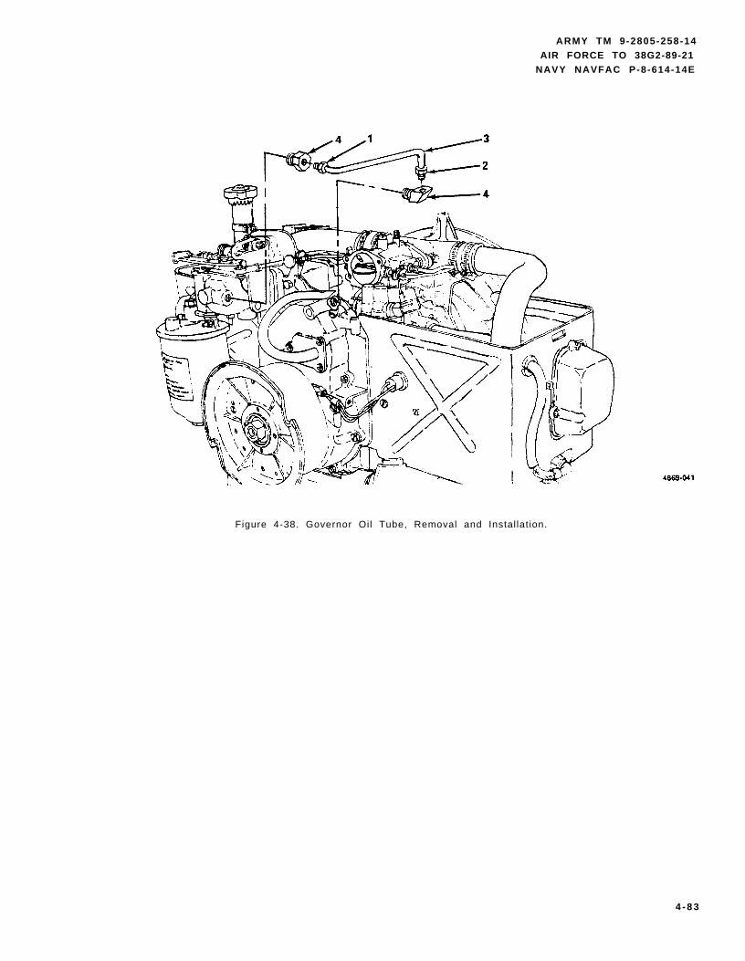
ARMY TM 9-2805-258-14AIR FORCE TO 38G2-89-21
NAVY NAVFAC P-8-614-14E
Figure 4-38. Governor Oil Tube, Removal and Installation.
4 - 8 3
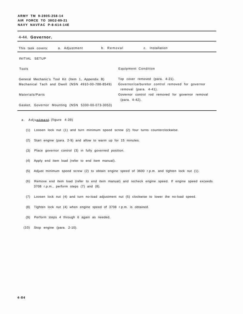
ARMY TM 9-2805-258-14AIR FORCE TO 38G2-89-21NAVY NAVFAC P-8-614-14E
4-44. Governor.
This task covers: a. Adjustment b . R e m o v a l c. Installation
INITIAL SETUP
Tools
General Mechanic’s Tool Kit (Item 1, Appendix B)
Mechanical Tach and Dwell (NSN 4910-00-788-8549)
Mater ia ls /Par ts
Gasket, Governor Mounting (NSN 5330-00-073-3053)
Equipment Condi t ion
Top cover removed (para. 4-21).
Governor/carburetor control removed for governor
removal (para. 4-41).
Governor control rod removed for governor removal
(para. 4-42).
a . A d j u s t m e n t. (figure 4-39)
(1)
(2)
(3)
(4)
(5)
(6)
(7)
(8)
(9)
(10)
4 - 8 4
Loosen lock nut (1) and turn minimum speed screw (2) four turns counterclockwise.
Start engine (para. 2-9) and allow to warm up for 15 minutes.
Place governor control (3) in fully governed position.
Apply end item load (refer to end item manual).
Adjust minimum speed screw (2) to obtain engine speed of 3600 r.p.m. and tighten lock nut (1).
Remove end item load (refer to end item manual) and recheck engine speed. If engine speed exceeds
3708 r.p.m., perform steps (7) and (8).
Loosen lock nut (4) and turn no-load adjustment nut (5) clockwise to lower the no-load speed.
Tighten lock nut (4) when engine speed of 3708 r.p.m. is obtained.
Perform steps 4 through 6 again as needed.
Stop engine (para. 2-10).
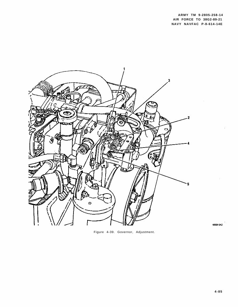
ARMY TM 9-2805-258-14AIR FORCE TO 38G2-89-21
NAVY NAVFAC P-8-614-14E
Figure 4-39. Governor, Adjustment.
4 - 8 5
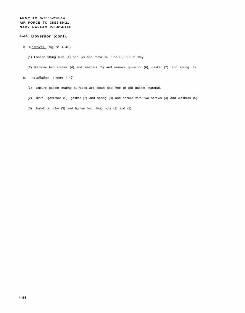
ARMY TM 9-2805-258-14AIR FORCE TO 38G2-89-21NAVY NAVFAC P-8-614-14E
4-44. Governor (cont).
b. Removal . ( f i g u r e 4 - 4 0 )
(1) Loosen fitting nuts (1) and (2) and move oil tube (3) out of way.
(2) Remove two screws (4) and washers (5) and remove governor (6), gasket (7), and spring (8).
c. Insta l la t ion. (figure 4-40)
(1)
(2)
(3)
Ensure gasket mating surfaces are clean and free of old gasket material.
Install governor (6), gasket (7) and spring (8) and secure with two screws (4) and washers (5).
Install oil tube (3) and tighten two fitting nuts (1) and (2).
4 - 8 6
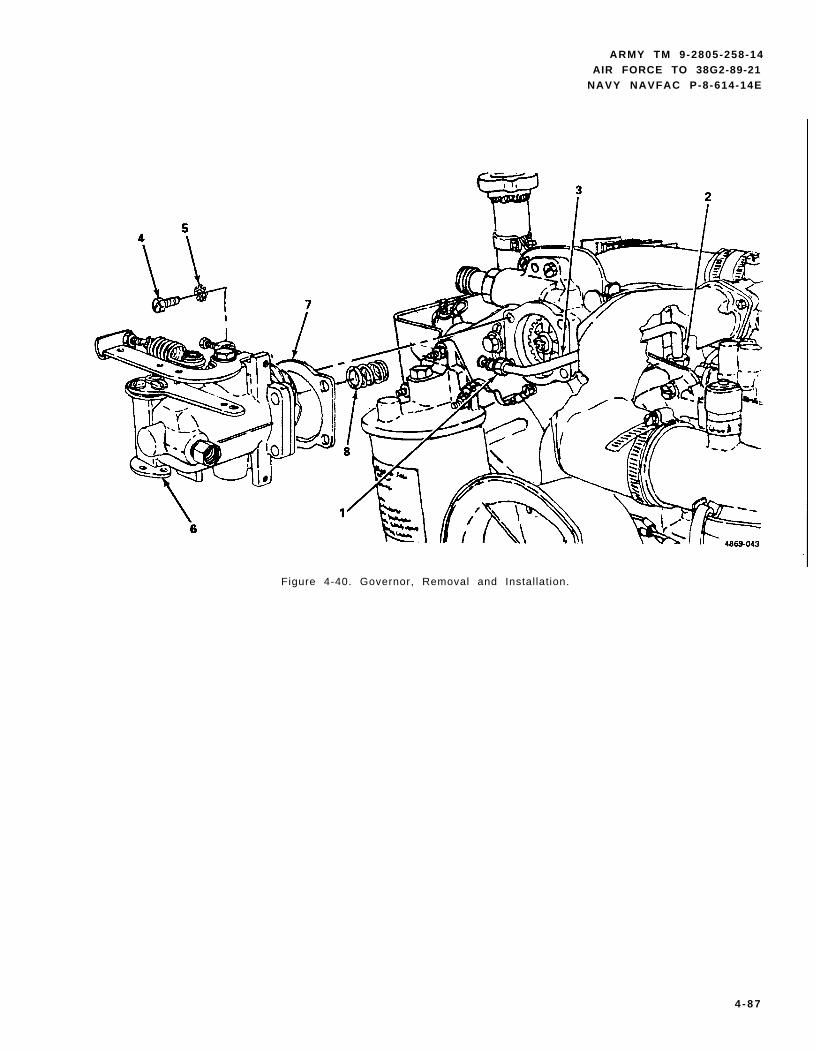
ARMY TM 9-2805-258-14AIR FORCE TO 38G2-89-21
NAVY NAVFAC P-8-614-14E
Figure 4-40. Governor, Removal and Installation.
4 - 8 7
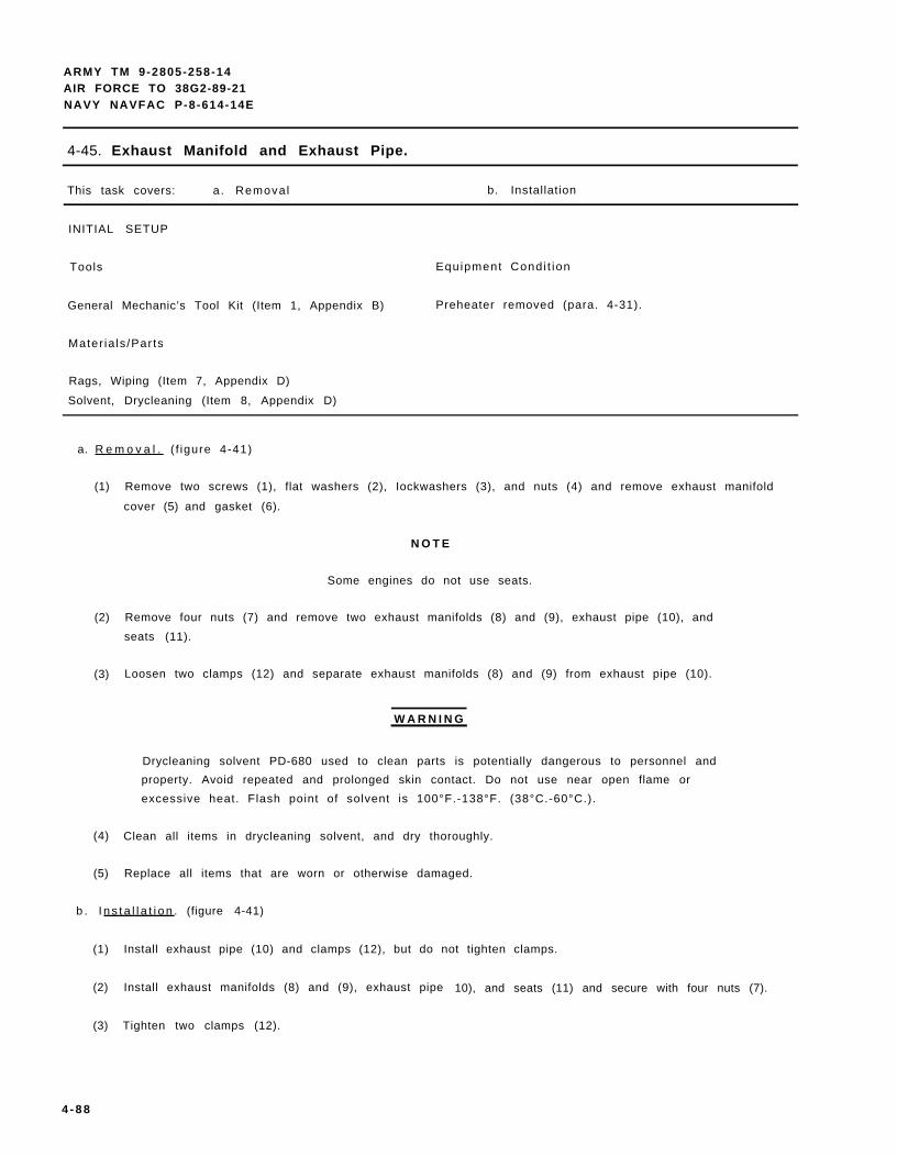
ARMY TM 9-2805-258-14AIR FORCE TO 38G2-89-21NAVY NAVFAC P-8-614-14E
4-45. Exhaust Manifold and Exhaust Pipe.
This task covers: a . Removal b. Installation
INITIAL SETUP
Tools Equipment Condi t ion
General Mechanic’s Tool Kit (Item 1, Appendix B) Preheater removed (para. 4-31).
Mater ia ls /Par ts
Rags, Wiping (Item 7, Appendix D)
Solvent, Drycleaning (Item 8, Appendix D)
a. R e m o v a l . ( f igure 4-41)
(1)
(2)
(3)
(4)
(5)
Remove two screws (1), flat washers (2), Iockwashers (3), and nuts (4) and remove exhaust manifold
cover (5) and gasket (6).
N O T E
Some engines do not use seats.
Remove four nuts (7) and remove two exhaust manifolds (8) and (9), exhaust pipe (10), and
seats (11).
Loosen two clamps (12) and separate exhaust manifolds (8) and (9) from exhaust pipe (10).
W A R N I N G
Drycleaning solvent PD-680 used to clean parts is potentially dangerous to personnel and
property. Avoid repeated and prolonged skin contact. Do not use near open flame or
excessive heat. Flash point of solvent is 100°F.-138°F. (38°C.-60°C.).
Clean all items in drycleaning solvent, and dry thoroughly.
Replace all items that are worn or otherwise damaged.
b . I n s t a l l a t i o n . (figure 4-41)
(1)
(2)
(3)
4 - 8 8
Install exhaust pipe (10) and clamps (12), but do not tighten clamps.
Install exhaust manifolds (8) and (9), exhaust pipe
Tighten two clamps (12).
10), and seats (11) and secure with four nuts (7).
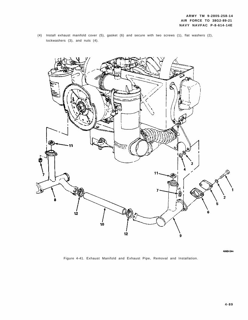
(4)
ARMY TM 9-2805-258-14AIR FORCE TO 38G2-89-21
NAVY NAVFAC P-8-614-14E
Install exhaust manifold cover (5), gasket (6) and secure with two screws (1), flat washers (2),
Iockwashers (3), and nuts (4).
Figure 4-41. Exhaust Manifold and Exhaust Pipe, Removal and Installation.
4 - 8 9
ARMY TM 9-2805-258-14AIR FORCE TO 38G2-89-21NAVY NAVFAC P-8-614-14E
4-46. Manual Choke.
This task covers: a . R e m o v a l b. Installation
INITIAL SETUP
Tools Equipment Condi t ion
General Mechanic’s Tool Kit (Item 1, Appendix B) Top cover removed (para. 4-21).
a. R e m o v a l . ( f igure 4-42)
(1) Remove screw (1), washer (2), nut (3) and remove manual choke (4) and clamp (5) from bracket (6).
(2) Remove manual choke (4) from choke lever (7) and spring (8).
b. Installation. ( f igure 4-42)
(1)
(2)
4 - 9 0
Connect manual choke (4) to choke lever (7) and spring (8).
Position manual choke (4) and clamp (5) on bracket (6) and secure with screw (1), washer (2), and
nut (3).
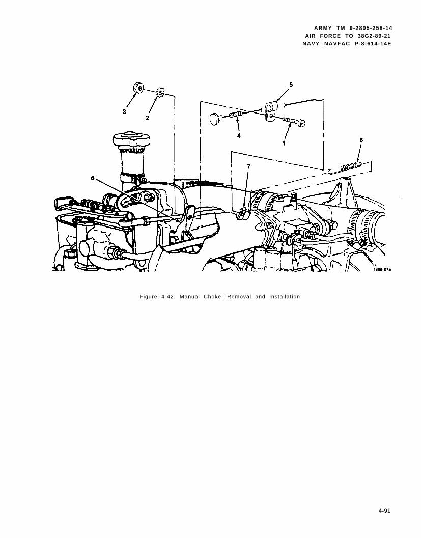
ARMY TM 9-2805-258-14AIR FORCE TO 38G2-89-21
NAVY NAVFAC P-8-614-14E
Figure 4-42. Manual Choke, Removal and Installation.
4-91
ARMY TM 9-2805-258-14
AIR FORCE TO 38G2-89-21NAVY NAVFAC P-8-614-14E
4-47. Carburetor.
This task covers: a. Adjustment b . Removal c. Installation
INITIAL SETUP
Tools Equipment Condi t ion
General Mechanic’s Tool Kit (Item 1, Appendix B) Air cleaner elbow removed for carburetor removal
(para. 4-17).
Mater ia ls /Par ts Top cover removed for carburetor adjustment
(para. 4-21).
Rags, Wiping (Item 7, Appendix D)
Solvent, Drycleaning (Item 8, Appendix D)
Gasket, Carburetor Mounting (NSN 5330-00-073-3049)
a. A d j u s t m e n t. (figure 4 - 4 3 )
(1) Turn air/fuel mixture screw (1) fully clockwise until seated.
(2) Turn air/fuel mixture screw (1) 1 1/2 turns counterclockwise.
(3) Start engine (para. 2-9) and operate at idle until warm.
N O T E
Ensure governor/carburetor is in full idle position.
(4) Adjust air/fuel mixture screw (1) until smooth idle is obtained.
(5) Stop engine (para. 2-10).
4 - 9 2
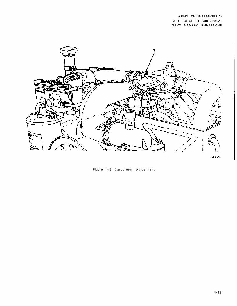
ARMY TM 9-2805-258-14AIR FORCE TO 38G2-89-21
NAVY NAVFAC P-8-614-14E
Figure 4-43. Carburetor , Adjustment .
4 - 9 3
ARMY TM 9-2805-258-14AIR FORCE TO 38G2-89-21NAVY NAVFAC P-8-614-14E
4-47. Carburetor (cont).
b. R e m o v a l . ( f i g u r e 4 - 4 4 )
(1) Remove screw (1) and washer (2) and remove governor control rod (3).
W A R N I N G
Do not smoke or use open flame in the vicinity of gasoline vapors.
(2) Loosen fitting nut (4) on fuel line (5).
(3) Loosen screw (6) and remove choke assembly (7) from choke rod (8).
(4) Remove screw (9), washer (10), and nut (11) securing manual choke clamp (12).
(5) Remove manual choke (13) and spring (14) from choke lever (15).
(6) Remove two nuts
( 2 0 ) .
16), Iockwashers (17) and flat washers (18) and remove carburetor (19) and gasket
W A R N I N G
Drycleaning solvent PD-680 used to clean parts is potentially dangerous to personnel and
property. Avoid repeated and prolonged skin contact. Do not use near open flame or
excessive heat. Flash point of solvent is 100°F.-138°F, (38°C.-6O°C.).
(7) Clean outside of carburetor (19) with drycleaning solvent and dry thoroughly.
(8) Inspect carburetor (19) and replace if carburetor body is cracked or otherwise damaged.
c. Installation. (figure 4-44)
(1)
(2)
(3)
(4)
(5)
(6)
(7)
4 - 9 4
Ensure all gasket mating surfaces are clean and free of old gasket material.
Install carburetor (19) and gasket (20) and secure with two nuts (16), Iockwashers (17), and flat
washers (18).
Install spring (14) and manual choke (13).
Install manual choke clamp (12) and secure with screw (9) and washer (10) and nut (11).
Install fuel line (5) and tighten fitting nut (4).
Position choke lever (15) in the full open position and install choke assembly (7) in horizontal position
and tighten screw (6).
Install governor control rod (3) and secure with screw (1) and washer (2).
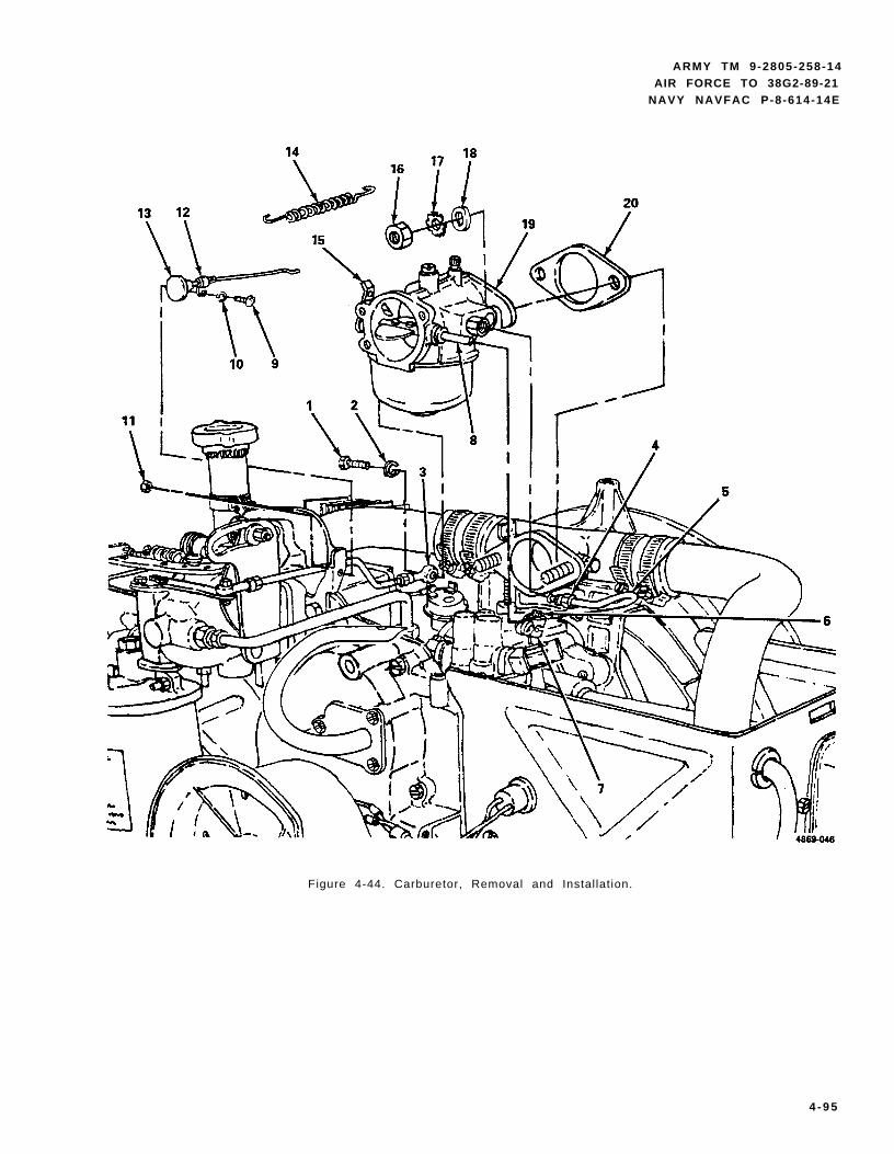
ARMY TM 9-2805-258-14AIR FORCE TO 38G2-89-21
NAVY NAVFAC P-8-614-14E
Figure 4-44. Carburetor, Removal and Installation.
4 - 9 5
ARMY TM 9-2805-258-14AIR FORCE TO 38G2-89-21NAVY NAVFAC P-8-614-14E
4-48. Fuel Line and Fittings.
This task covers: a . R e m o v a l b . Ins ta l la t ion
INITIAL SETUP
T o o l s E q u i p m e n t C o n d i t i o n
General Mechanic’s Tool Kit (Item 1, Appendix B) Top cover removed (para. 4-21)
M a t e r i a l s / P a r t s
Rags, Wiping (Item 7, Appendix D)
Solvent, Drycleaning (Item 8, Appendix D)
a . R e m o v a l ( f i g u r e 4 - 4 5 )
(1)
(2)
(3)
(4)
( 5 )
W A R N I N G
Do not smoke or use open flame in the vicinity of gasoline vapors.
Loosen fitting nut (1).
Loosen fitting nut (2) and remove fuel line (3).
W A R N I N G
Drycleaning solvent PD-680 used to clean parts is potentially dangerous to personnel and
property. Avoid repeated and prolonged skin contact. Do not use near open flame or
excessive heat. Flash point of solvent is 100°F.-138°F. (38°C.-6O°C.).
Clean fuel line (3) with drycleaning solvent and dry thoroughly.
Inspect fuel line (3) and replace if fitting nuts (1) and (2) are stripped or fuel line (3) is dented or
otherwise damaged.
Inspect fittings (4) and replace if damaged.
b . I n s t a l l a t i o n . ( f i g u r e 4 - 4 5 )
Install fuel line (3) and tighten fitting nuts (1) and (2).
4 - 9 6
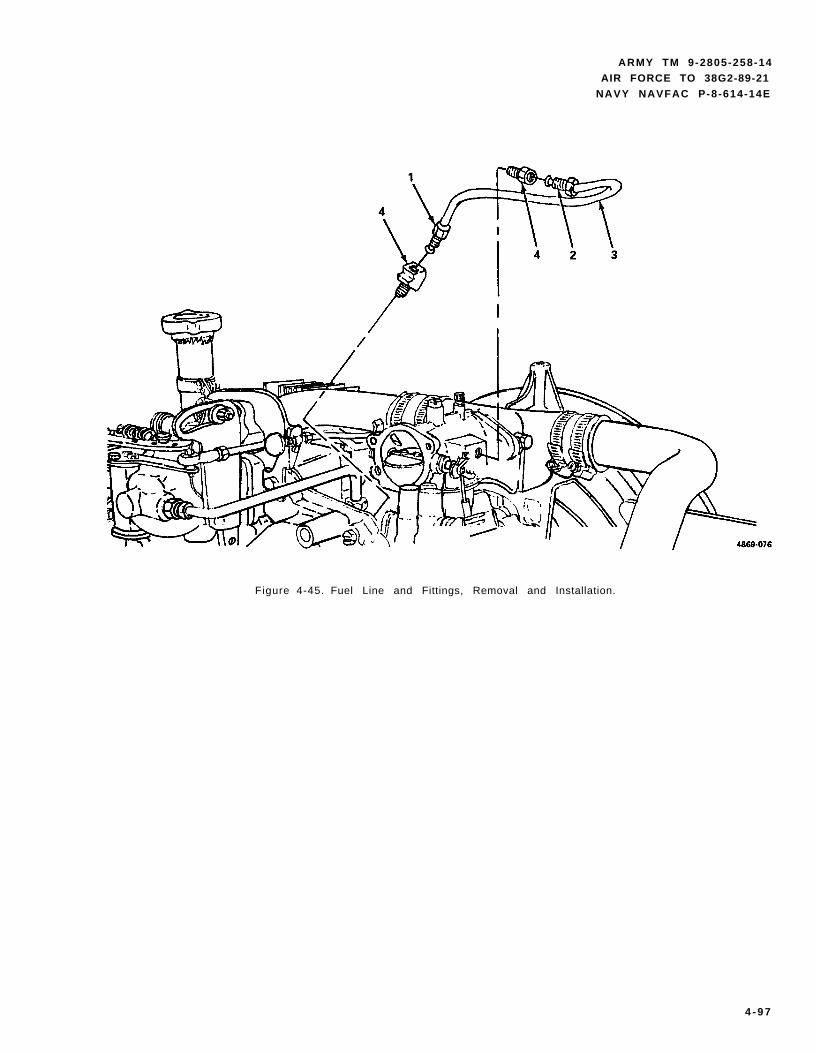
ARMY TM 9-2805-258-14AIR FORCE TO 38G2-89-21
NAVY NAVFAC P-8-614-14E
Figure 4-45. Fuel Line and Fittings, Removal and Installation.
4 - 9 7
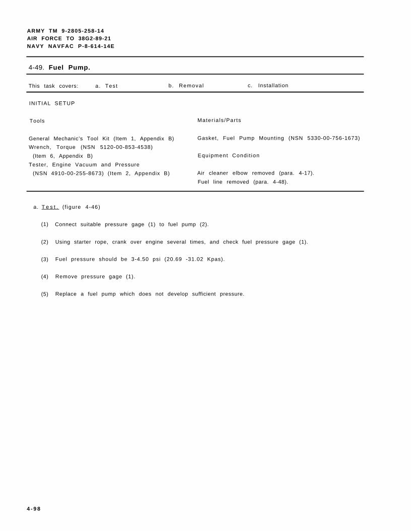
ARMY TM 9-2805-258-14AIR FORCE TO 38G2-89-21NAVY NAVFAC P-8-614-14E
4-49. Fuel Pump.
This task covers: a . Tes t b . Removal c. Installation
INITIAL SETUP
Tools Mater ia ls /Par ts
General Mechanic’s Tool Kit (Item 1, Appendix B) Gasket, Fuel Pump Mounting (NSN 5330-00-756-1673)
Wrench, Torque (NSN 5120-00-853-4538)
(Item 6, Appendix B) Equipment Condi t ion
Tester, Engine Vacuum and Pressure
(NSN 4910-00-255-8673) (Item 2, Appendix B) Air cleaner elbow removed (para. 4-17).
Fuel line removed (para. 4-48).
a. T e s t . ( f igure 4-46)
(1)
(2)
(3)
(4)
(5)
Connect suitable pressure gage (1) to fuel pump (2).
Using starter rope, crank over engine several times, and check fuel pressure gage (1).
Fuel pressure should be 3-4.50 psi (20.69 -31.02 Kpas).
Remove pressure gage (1).
Replace a fuel pump which does not develop sufficient pressure.
4 - 9 8
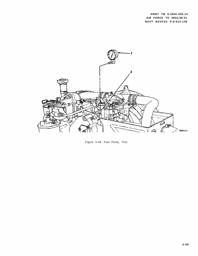
ARMY TM 9-2805-258-14AIR FORCE TO 38G2-89-21
NAVY NAVFAC P-8-614-14E
Figure 4-46. Fuel Pump, Test.
4 - 9 9
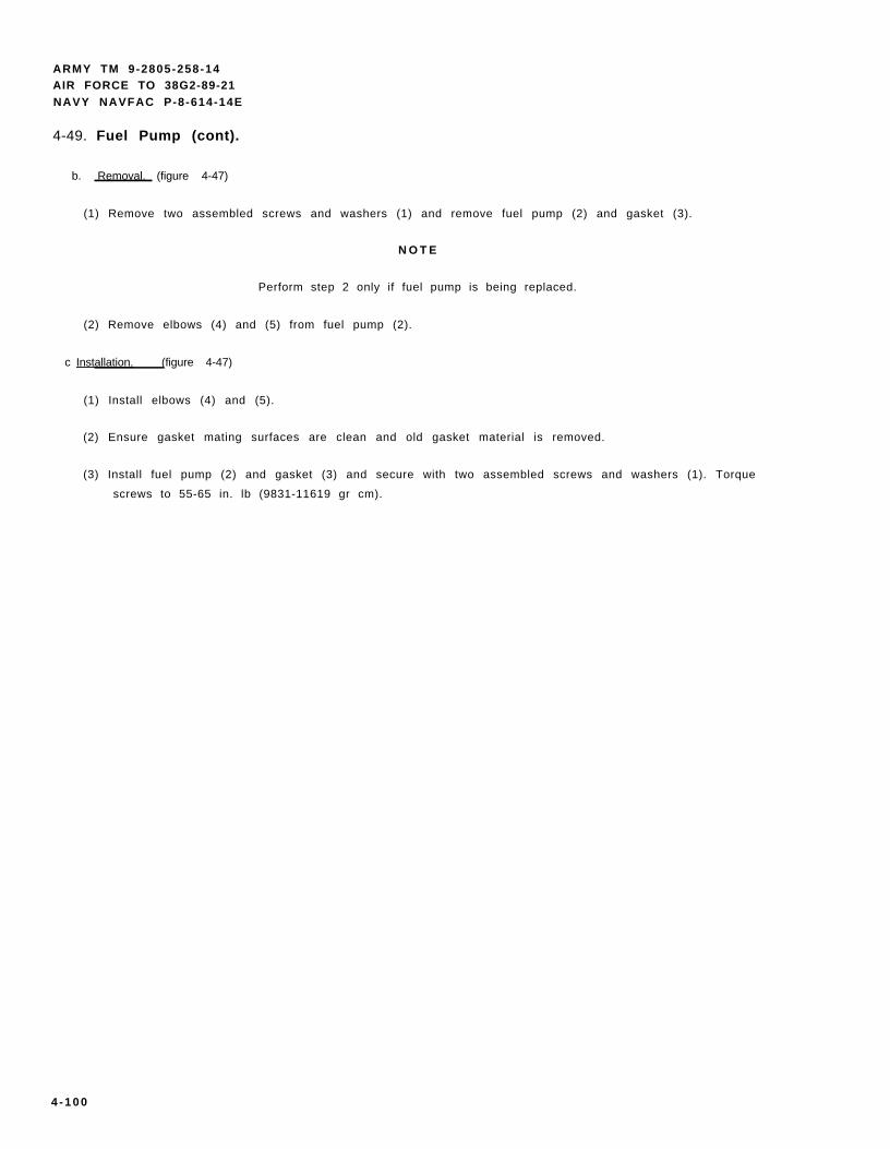
ARMY TM 9-2805-258-14AIR FORCE TO 38G2-89-21NAVY NAVFAC P-8-614-14E
4-49. Fuel Pump (cont).
b. Removal. (figure 4-47)
(1) Remove two assembled screws and washers (1) and remove fuel pump (2) and gasket (3).
N O T E
Perform step 2 only if fuel pump is being replaced.
(2) Remove elbows (4) and (5) from fuel pump (2).
c Installation. (figure 4-47)
(1) Install elbows (4) and (5).
(2) Ensure gasket mating surfaces are clean and old gasket material is removed.
(3) Install fuel pump (2) and gasket (3) and secure with two assembled screws and washers (1). Torque
screws to 55-65 in. lb (9831-11619 gr cm).
4 - 1 0 0
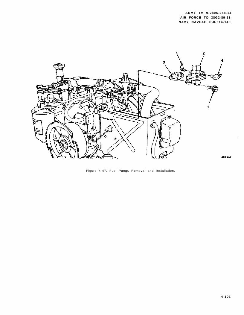
ARMY TM 9-2805-258-14AIR FORCE TO 38G2-89-21
NAVY NAVFAC P-8-614-14E
Figure 4-47. Fuel Pump, Removal and Installation.
4-101
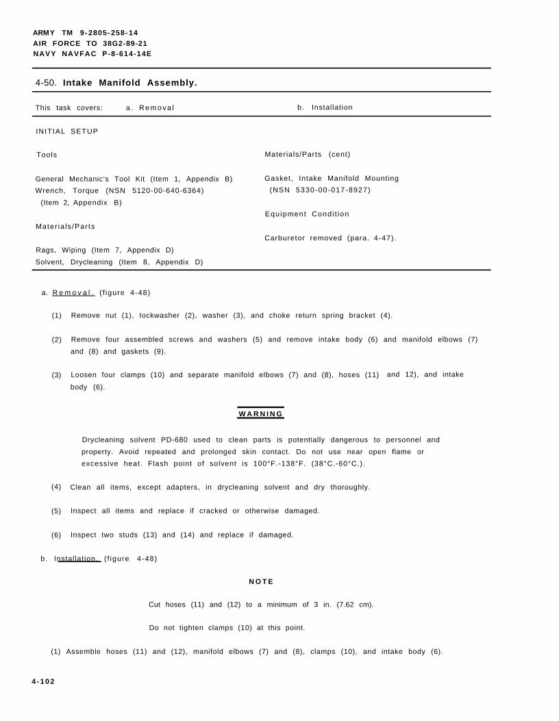
A R M Y T M 9 - 2 8 0 5 - 2 5 8 - 1 4AIR FORCE TO 38G2-89-21NAVY NAVFAC P-8-614-14E
4-50. Intake Manifold Assembly.
This task covers: a . R e m o v a l b. Installation
INITIAL SETUP
Tools Materials/Parts (cent)
General Mechanic’s Tool Kit (Item 1, Appendix B) Gasket, Intake Manifold Mounting
Wrench, Torque (NSN 5120-00-640-6364) (NSN 5330-00-017-8927)
(Item 2, Appendix B)
Equipment Condi t ion
Mater ia ls /Par ts
Carburetor removed (para. 4-47).
Rags, Wiping (Item 7, Appendix D)
Solvent, Drycleaning (Item 8, Appendix D)
a. R e m o v a l . ( f igure 4-48)
(1)
(2)
(3)
(4)
(5)
(6)
Remove nut (1), Iockwasher (2), washer (3), and choke return spring bracket (4).
Remove four assembled screws and washers (5) and remove intake body (6) and manifold elbows (7)
and (8) and gaskets (9).
Loosen four clamps (10) and separate manifold elbows (7) and (8), hoses (11)
body (6).
and 12), and intake
W A R N I N G
Drycleaning solvent PD-680 used to clean parts is potentially dangerous to personnel and
property. Avoid repeated and prolonged skin contact. Do not use near open flame or
excessive heat. Flash point of solvent is 100°F.-138°F. (38°C.-60°C.).
Clean all items, except adapters, in drycleaning solvent and dry thoroughly.
Inspect all items and replace if cracked or otherwise damaged.
Inspect two studs (13) and (14) and replace if damaged.
b. Installation. ( f igure 4-48)
N O T E
Cut hoses (11) and (12) to a minimum of 3 in. (7.62 cm).
Do not tighten clamps (10) at this point.
(1) Assemble hoses (11) and (12), manifold elbows (7) and (8), clamps (10), and intake body (6).
4 - 1 0 2
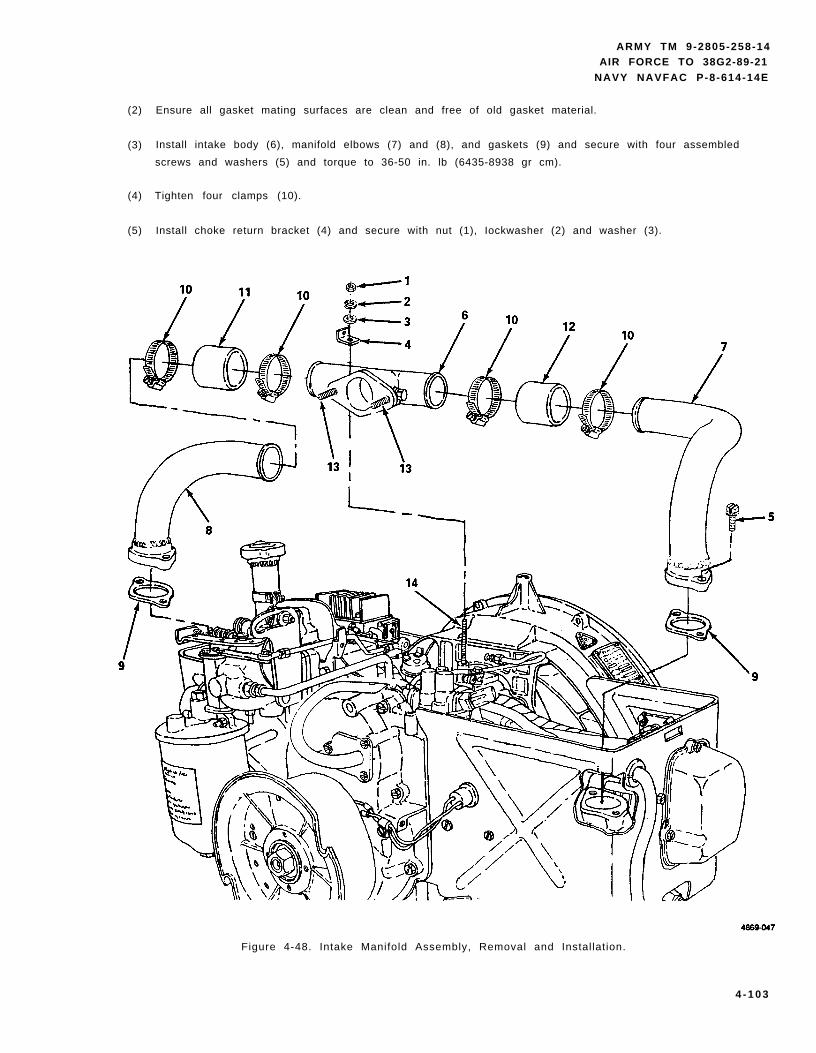
(2)
(3)
(4)
(5)
ARMY TM 9-2805-258-14AIR FORCE TO 38G2-89-21
NAVY NAVFAC P-8-614-14E
Ensure all gasket mating surfaces are clean and free of old gasket material.
Install intake body (6), manifold elbows (7) and (8), and gaskets (9) and secure with four assembled
screws and washers (5) and torque to 36-50 in. lb (6435-8938 gr cm).
Tighten four clamps (10).
Install choke return bracket (4) and secure with nut (1), Iockwasher (2) and washer (3).
Figure 4-48. Intake Manifold Assembly, Removal and Installation.
4 - 1 0 3
ARMY TM 9-2805-258-14
AIR FORCE TO 38G2-89-21NAVY NAVFAC P-8-614-14E
4-51. Rocker Box Cover.
This task covers: a . Removal b. Installation
INITIAL SETUP
Tools Mater ia ls /Par ts
General Mechanic’s Tool Kit (Item 1, Appendix B) Rags, Wiping (Item 7, Appendix D)
Solvent, Drycleaning (Item 8, Appendix D)
Gasket, Rocker Arm Cover Mounting
(NSN 53030-00-073-3023)
a. R e m o v a l . ( f igure 4-49)
(1)
(2)
(3)
(4)
Remove three assembled screws and washers (1) and remove rocker box cover (2) and gasket (3).
W A R N I N G
Drycleaning solvent PD-680 used to clean parts is potentially dangerous to personnel and
property. Avoid repeated and prolonged skin contact. Do not use near open flame or
excessive heat. Flash point of solvent is 100°F.-138°F. (38°C.-6O°C.).
Clean rocker box cover (2) in drycleaning solvent, and dry thoroughly.
Inspect rocker box cover for cracks and replace if cracked or otherwise damaged.
Repeat steps 1 thru 4 for remaining rocker box cover.
b. Insta l la t ion. (figure 4-49)
Install rocker box cover (2) and new gasket (3) and secure with three assembled screws and
washers (1).
4 - 1 0 4
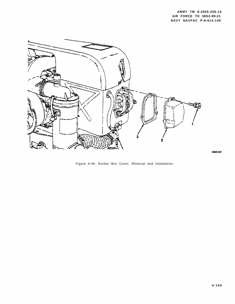
ARMY TM 9-2805-258-14AIR FORCE TO 38G2-89-21
NAVY NAVFAC P-8-614-14E
Figure 4-49. Rocker Box Cover, Removal and Installation.
4 - 1 0 5
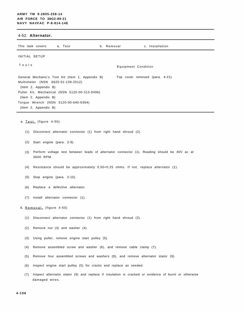
ARMY TM 9-2805-258-14
AIR FORCE TO 38G2-89-21NAVY NAVFAC P-8-814-14E
4-52. Alternator.
This task covers: a . Tes t b . Removal c . Ins ta l la t ion
INITIAL SETUP
T o o l s
General Mechanic’s Tool Kit (Item 1, Appendix B)
Multi imeter (NSN 6625-01-139-2512)
(Item 2, Appendix B)
Puller Kit, Mechanical (NSN 5120-00-313-9496)
(Item 2, Appendix B)
Torque Wrench (NSN 5120-00-640-6364)
(Item 2, Appendix B)
a. T e s t . ( f igure 4-50)
(1)
(2)
(3)
(4)
(5)
(6)
(7)
Disconnect alternator connector (1) from right hand shroud (2).
Start engine (para. 2-9).
Perform voltage test between leads of alternator connector (1). Reading should be 40V ac at
3600 RPM.
Resistance should be approximately 0.50+0.25 ohms. If not, replace alternator (1).
Stop engine (para. 2-10).
Replace a defective alternator.
Install alternator connector (1).
6. R e m o v a l . ( f igure 4-50)
(1)
(2)
(3)
(4)
(5)
(6)
(7)
4 - 1 0 6
Disconnect alternator connector (1) from right hand shroud (2).
Remove nut (3) and washer (4).
Using puller, remove engine start pulley (5).
Remove assembled screw and washer (6), and remove cable clamp (7).
Remove four assembled screws and washers (8), and remove alternator stator (9).
Inspect engine start pulley (5) for cracks and replace as needed.
Inspect alternator stator (9) and replace if insulation is cracked or evidence of burnt or otherwise
damaged wires.
Equipment Condi t ion
Top cover removed (para. 4-21).
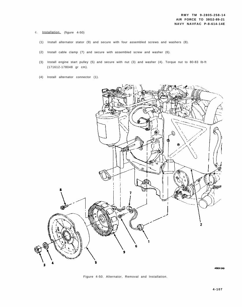
R M Y T M 9 - 2 8 0 5 - 2 5 8 - 1 4AIR FORCE TO 38G2-89-21
NAVY NAVFAC P-8-614-14E
c. Installation. (figure 4-50)
(1)
(2)
(3)
(4)
Install alternator stator (9) and secure with four assembled screws and washers (8).
Install cable clamp (7) and secure with assembled screw and washer (6).
Install engine start pulley (5) and secure with nut (3) and washer (4). Torque nut to 80-83 Ib-ft
(171612-178048 gr cm).
Install alternator connector (1).
Figure 4-50. Alternator, Removal and Installation.
4 - 1 0 7
ARMY TM 9-2805-258-14AIR FORCE TO 38G2-21NAVY NAVFAC P-8-614-14E
4-53. Wiring Harness.
This task covers: a. Test b. Removal. c. Installation
INITIAL SET UP
Tools Equipment Condition
General Mechanics Tool Kit (em 1, Appendix B) Top cover removed (para 4-21).Mutimeter (NSN 6625-01-139-2512) Air cleaner removed (para 4-15).
(Item 2, Appendix B)
a. Test. (figure4-51)
Perform end to end continuity test on wiring harness (1). (Refer to figure 4-55).
b. Removal. (figure 4-51)
(1) Tag and remove wiring harness led from starter solenoid (1), oil shutdown switch (2), oil pressure transmitter(3), magneto (4), regulator-rectifier connector (5) and alternator connector (6).
(2) Remove harness (7) from dips (8).
(3) Remove four screws (9) and remove wiring harness (7).
c. Installation. (figure 4-51)
(1) Install wiring harness (7) and secure with four screws (9).
(2) Install wiring harness (7) in dips (8).
(3) Install wiring harness leads and connectors as tagged.
4-108 Change 1
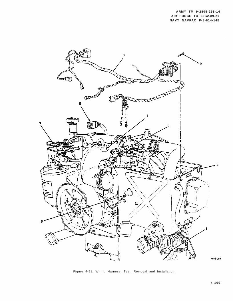
ARMY TM 9-2805-258-14AIR FORCE TO 38G2-89-21
NAVY NAVFAC P-8-614-14E
Figure 4-51. Wiring Harness, Test, Removal and Installation.
4 - 1 0 9
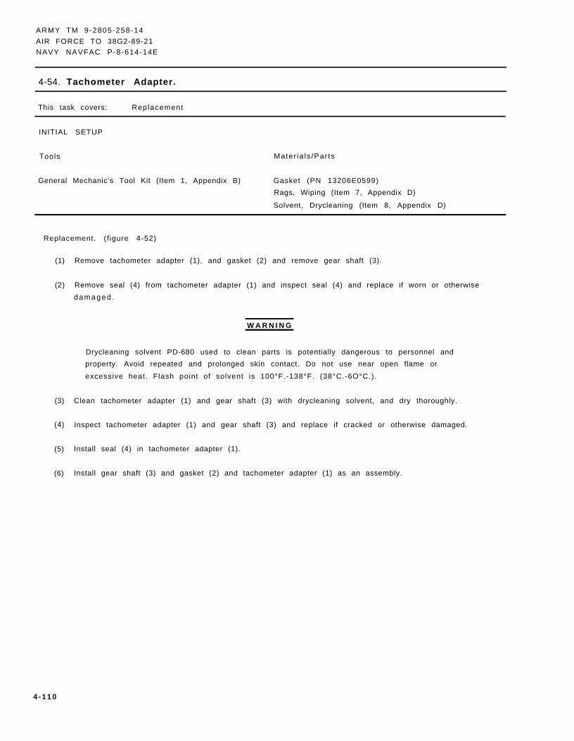
ARMY TM 9-2805-258-14
AIR FORCE TO 38G2-89-21
NAVY NAVFAC P-8-614-14E
4-54. Tachometer Adapter.
This task covers: Replacement
INITIAL SETUP
Tools Mater ia ls /Par ts
General Mechanic’s Tool Kit (Item 1, Appendix B) Gasket (PN 13206E0599)
Rags, Wiping (Item 7, Appendix D)
Solvent, Drycleaning (Item 8, Appendix D)
Replacement. (f igure 4-52)
(1)
(2)
(3)
(4)
(5)
(6)
4 - 1 1 0
Remove tachometer adapter (1), and gasket (2) and remove gear shaft (3).
Remove seal (4) from tachometer adapter (1) and inspect seal (4) and replace if worn or otherwise
d a m a g e d .
W A R N I N G
Drycleaning solvent PD-680 used to clean parts is potentially dangerous to personnel and
property. Avoid repeated and prolonged skin contact. Do not use near open flame or
excessive heat. Flash point of solvent is 100°F.-138°F. (38°C.-6O°C.).
Clean tachometer adapter (1) and gear shaft (3) with drycleaning solvent, and dry thoroughly.
Inspect tachometer adapter (1) and gear shaft (3) and replace if cracked or otherwise damaged.
Install seal (4) in tachometer adapter (1).
Install gear shaft (3) and gasket (2) and tachometer adapter (1) as an assembly.
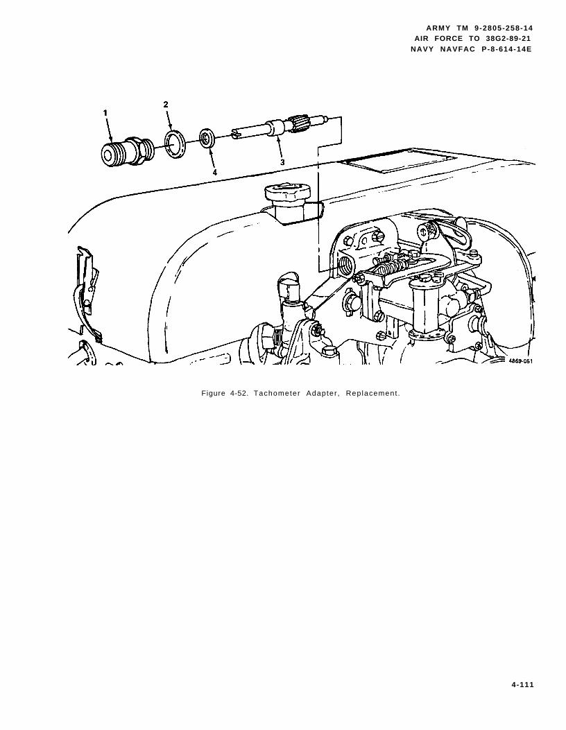
ARMY TM 9-2805-258-14AIR FORCE TO 38G2-89-21
NAVY NAVFAC P-8-614-14E
Figure 4-52. Tachometer Adapter , Replacement .
4-111
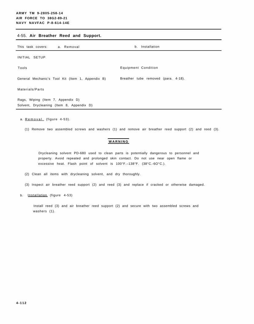
ARMY TM 9-2805-258-14
AIR FORCE TO 38G2-89-21NAVY NAVFAC P-8-614-14E
4-55. Air Breather Reed and Support.
This task covers: a . Removal b. Installation
INITIAL SETUP
Tools Equipment Condi t ion
General Mechanic’s Tool Kit (Item 1, Appendix B) Breather tube removed (para. 4-18).
Mater ia ls /Par ts
Rags, Wiping (Item 7, Appendix D)
Solvent, Drycleaning (Item 8, Appendix D)
a. R e m o v a l . ( f igure 4-53) .
(1) Remove two assembled screws and washers (1) and remove air breather reed support (2) and reed (3).
W A R N I N G
Drycleaning solvent PD-680 used to clean parts is potentially dangerous to personnel and
property. Avoid repeated and prolonged skin contact. Do not use near open flame or
excessive heat. Flash point of solvent is 100°F.–138°F. (38°C.-6O°C.).
(2) Clean all items with drycleaning solvent, and dry thoroughly.
(3) Inspect air breather reed support (2) and reed (3) and replace if cracked or otherwise damaged.
b. Ins ta I la t ion. (figure 4-53)
Install reed (3) and air breather reed support (2) and secure with two assembled screws and
washers (1).
4 - 1 1 2
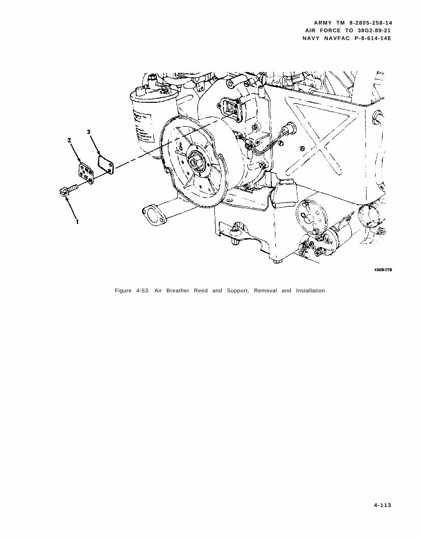
ARMY TM 9-2805-258-14AIR FORCE TO 38G2-89-21
NAVY NAVFAC P-8-614-14E
Figure 4-53. Air Breather Reed and Support, Removal and Installation.
4 - 1 1 3
ARMY TM 9-2805-258-14AIR FORCE TO 38G2-89-21NAVY NAVFAC P-8-614-14E
4-56. Compression Test.
This task covers: Test
INITIAL SET UP
Tools
General Mechanic’s Tool Kit (Item 1, Appendix B)Wrench, Torque (NSN 5120-0 640-6364)
(Item 2, Appendix B)
Test. (figure 4-54)
(1) Loosen connector nut (1) and remove high tension cable (2).
(2) Remove spark plug (3).
(3) Install suitable pressure gage (4).
(4) Using starter rope, crank engine over several times and check pressure gage reading.
(5) Compression reading should be 90 psi (620 Kpas) at sea level. The reading will be less above sea level.
(6) Remove pressure gage (4).
(7) Install spark plug (3).
(8) Install high tension cable (2) and tighten connector nut (1).
(9) Repeat steps 1 through 8 for remaining cylinder.
(10) Compare readings from each cylinder. The readings should be within 25 psi (173 Kpas) of each other. Furtherengine inspection is required if any one reading is inaccurate.
4-114 Change 1
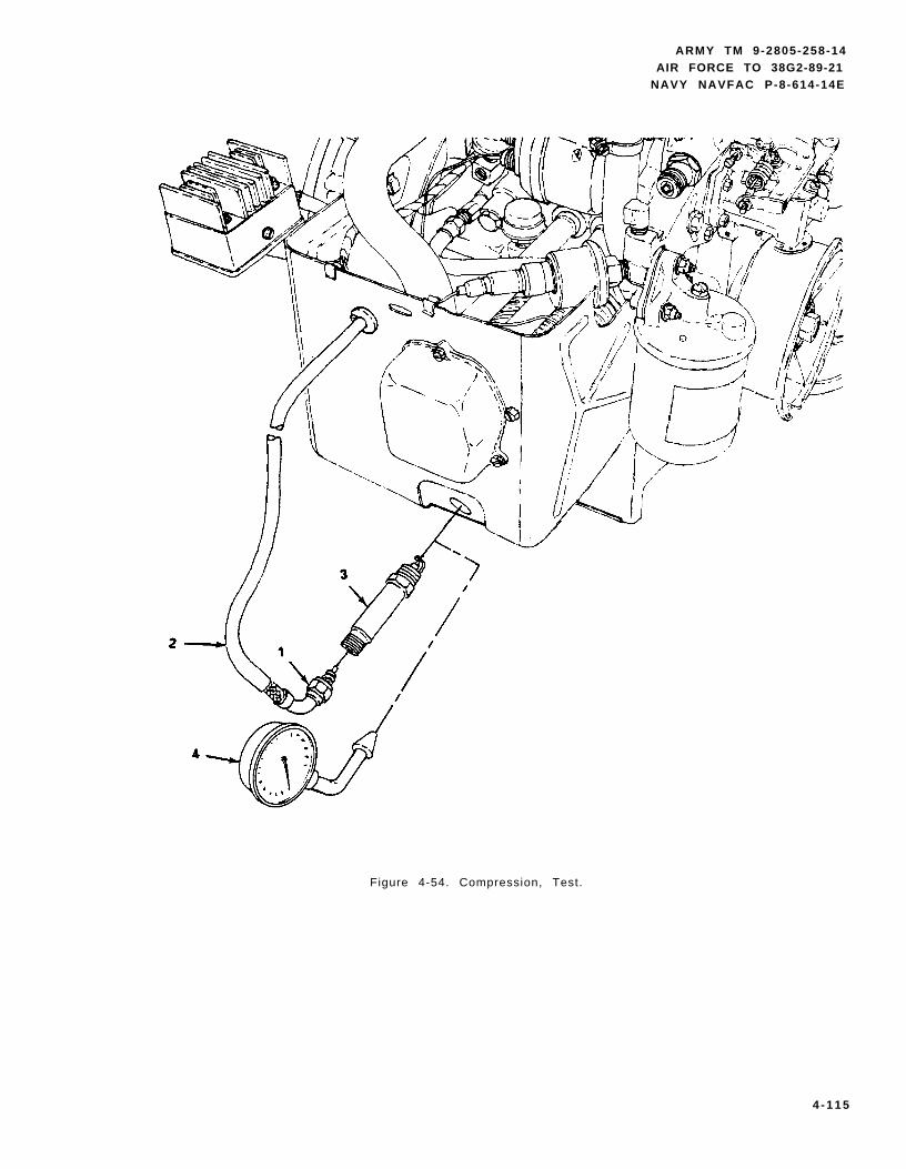
ARMY TM 9-2805-258-14AIR FORCE TO 38G2-89-21
NAVY NAVFAC P-8-614-14E
Figure 4-54. Compression, Test.
4 - 1 1 5
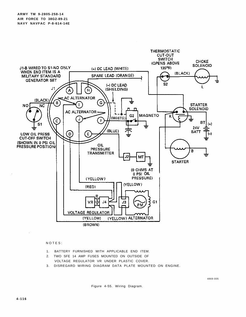
ARMY TM 9-2805-258-14
AIR FORCE TO 38G2-89-21NAVY NAVFAC P-8-614-14E
N O T E S :
1. BATTERY FURNISHED WITH APPLICABLE END ITEM.
2. TWO SFE 14 AMP FUSES MOUNTED ON OUTSIDE OF
VOLTAGE REGULATOR VR UNDER PLASTIC COVER.
3. DISREGARD WIRING DIAGRAM DATA PLATE MOUNTED ON ENGINE.
4869-005
Figure 4-55. Wiring Diagram.
4 - 1 1 6
Section VI.
Paragraph
4 - 5 7 General . . . . . . . . .
ARMY TM 9-2805-258-14AIR FORCE TO 38G2-89-21
NAVY NAVFAC P-8-614-14E
PREPARATION FOR SHIPMENT OR STORAGE
P a g e
. . . . . . . . . . . . . . . . . . . . . . . . . . . . . . . . . . . . . . . . . . . . . . . . . . . . . 4 - 1 1 7
4 - 5 8 Short Term andlntermediate Storage Procedures . . . . . . . . . . . . . . . . . . . . . . . . . . ...4-117
4 - 5 9 Administrative Storage . . . . . . . . . . . . . . . . . . . . . . . . . . . . . . . . . . . . . . . . . . . . . . . . ...4-117
4-57. General. This section contains procedures to place the engine into either short term or intermediate
s torage.
N O T E
The procedures for placing the engine into either short term or intermediate storage are
the same.
4-58. Short Term and Intermediate Storage Procedures.
a.
b.
c.
d.
e.
Perform operator Before and After and Unit PMCS.
Remove end item fuel supply.
Drain fuel system.
Drain engine oil.
Secure fuel filter and starter rope to engine.
4-59. Administrative Storage.
a. Placement of equipment in administrative storage should be for short periods of time when a shortage of
maintenance effort exists. Items should be in mission readiness within 24 hours or within the time factors as
determined by the directing authority. During the storage period appropriate maintenance records will be kept.
b. Before placing equipment in administrative storage, current maintenance services and equipment
serviceable criteria (ESC) evaluations should be corrected, and all modification work orders (MWO’S) should be
appl ied.
c. Storage site selection. Inside storage is preferred for i tems selected for administrative storage. If inside
storage is not available, trucks, vans, conex containers and other containers maybe used.
4-117/(4-118 blank)

ARMY TM 9-2805-258-14AIR FORCE TO 38G2-89-21
NAVY NAVFAC P-8-614-14E
C H A P T E R 5
D I R E C T S U P P O R T M A I N T E N A N C E I N S T R U C T I O N S
Sect ion P a g e
OVERVIEW . . . . . . . . . . . . . . . . . . . . . . . . . . . . . . . . . . . . . . . . . . . . . . . . . . . . . . . . . . . . . . . ...5-1
Section l. Repair Parts;Special Tools; Test, Measurement, Diagnostic
Equipment (TMDE); and Support Equipment . . . . . . . . . . . . . . . . . . . . . . . . . . . . . . 5-1
Section Il. Direct Support Troubleshooting . . . . . . . . . . . . . . . . . . . . . . . . . . . . . . . . . . . . . . ...5-1
Section ll l. Direct Support Maintenance Procedures . . . . . . . . . . . . . . . . . . . . . . . . . . . . . . . ...5-4
O V E R V I E W
This chapter contains information for troubleshooting and maintenance of the engine by Direct Support
Maintenance personnel .
Section l . REPAIR PARTS; SPECIAL TOOLS; TEST, MEASUREMENT,
DIAGNOSTIC EQUIPMENT (TMDE); AND SUPPORT EQUIPMENT
Paragraph
P a g e
5-1 Common Tools and Test Equipment . . . . . . . . . . . . . . . . . . . . . . . . . . . . . . . . . . . . . . ...5-1
5 - 2 Special Tools, TMDE, and Support Equipment . . . . . . . . . . . . . . . . . . . . . . . . . . . . . . . . .5-1
5 - 3 Repair Parts . . . . . . . . . . . . . . . . . . . . . . . . . . . . . . . . . . . . . . . . . . . . . . . . . . . . . . . . ...5-1
5-1. Common Tools and Equipment. For authotized common tools and equipment, refer to the Modified
Table of Organization and Equipment (MTOE) applicable to your unit.
5-2. Special Tools, TMDE and Support Equipment. For a listing of special tools, TMDE, and support
equipment authorized for use on this equipment, refer to the Repair Parts and Special Tools List, TM 5-2805-258-
24P, and the maintenance allocation chart (MAC), appendix B of this manual.
5-3. Repair parts. Repair parts are listed and illustrated in the Repair Parts and Special Tools List for 10 HP
Military Standard Engine, TM 5-2805-258-24P.
Section I l . DIRECT SUPPORT TROUBLESHOOTING
Paragraph
P a g e
5 - 4 General . . . . . . . . . . . . . . . . . . . . . . . . . . . . . . . . . . . . . . . . . . . . . . . . . . . . . . . . . . . . ...5-2
5 - 5 Direct Support Troubleshooting Procedures . . . . . . . . . . . . . . . . . . . . . . . . . . . . . . . . ...5-2
5-1
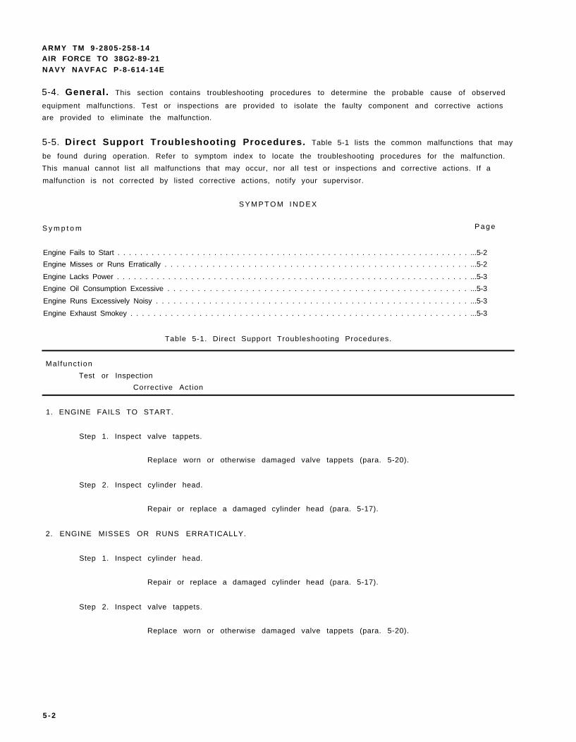
ARMY TM 9-2805-258-14AIR FORCE TO 38G2-89-21NAVY NAVFAC P-8-614-14E
5-4. General. This section contains troubleshooting procedures to determine the probable cause of observed
equipment malfunctions. Test or inspections are provided to isolate the faulty component and corrective actions
are provided to eliminate the malfunction.
5-5. Direct Support Troubleshooting Procedures. Table 5-1 lists the common malfunctions that may
be found during operation. Refer to symptom index to locate the troubleshooting procedures for the malfunction.
This manual cannot list all malfunctions that may occur, nor all test or inspections and corrective actions. If a
malfunction is not corrected by listed corrective actions, notify your supervisor.
S Y M P T O M I N D E X
S y m p t o m P a g e
Engine Fails to Start . . . . . . . . . . . . . . . . . . . . . . . . . . . . . . . . . . . . . . . . . . . . . . . . . . . . . . . . . . . . . . ...5-2
Engine Misses or Runs Erratically . . . . . . . . . . . . . . . . . . . . . . . . . . . . . . . . . . . . . . . . . . . . . . . . . . . ...5-2
Engine Lacks Power . . . . . . . . . . . . . . . . . . . . . . . . . . . . . . . . . . . . . . . . . . . . . . . . . . . . . . . . . . . . . . ...5-3
Engine Oil Consumption Excessive . . . . . . . . . . . . . . . . . . . . . . . . . . . . . . . . . . . . . . . . . . . . . . . . . . ...5-3
Engine Runs Excessively Noisy . . . . . . . . . . . . . . . . . . . . . . . . . . . . . . . . . . . . . . . . . . . . . . . . . . . . . ...5-3
Engine Exhaust Smokey . . . . . . . . . . . . . . . . . . . . . . . . . . . . . . . . . . . . . . . . . . . . . . . . . . . . . . . . . . . ...5-3
Table 5-1. Direct Support Troubleshooting Procedures.
Mal funct ion
Test or Inspection
Corrective Action
1. ENGINE FAILS TO START.
Step 1. Inspect valve tappets.
Replace worn or otherwise damaged valve tappets (para. 5-20).
Step 2. Inspect cylinder head.
Repair or replace a damaged cylinder head (para. 5-17).
2. ENGINE MISSES OR RUNS ERRATICALLY.
Step 1. Inspect cylinder head.
Repair or replace a damaged cylinder head (para. 5-17).
Step 2. Inspect valve tappets.
Replace worn or otherwise damaged valve tappets (para. 5-20).
5 - 2
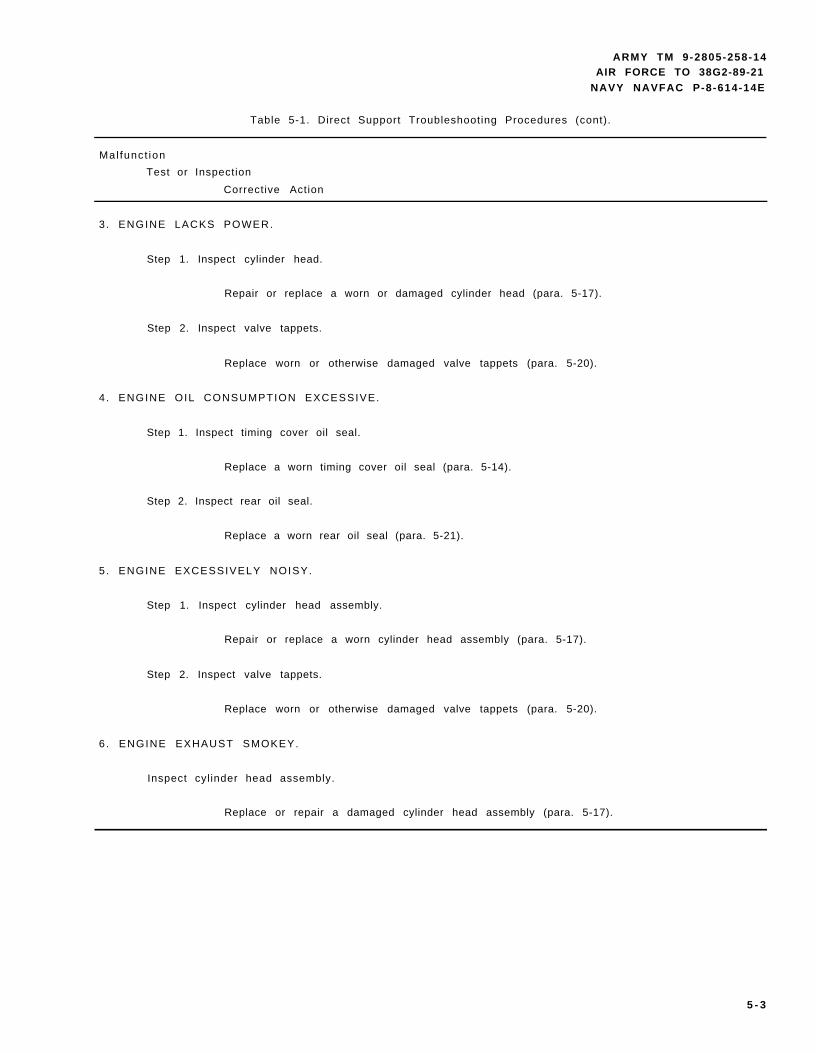
ARMY TM 9-2805-258-14AIR FORCE TO 38G2-89-21
NAVY NAVFAC P-8-614-14E
Table 5-1. Direct Support Troubleshooting Procedures (cont).
Mal funct ion
Test or Inspection
Corrective Action
3 . ENGINE LACKS POWER.
Step 1. Inspect cylinder head.
Repair or replace a worn or damaged cylinder head (para. 5-17).
Step 2. Inspect valve tappets.
Replace worn or otherwise damaged valve tappets (para. 5-20).
4 . ENGINE OIL CONSUMPTION EXCESSIVE.
Step 1. Inspect timing cover oil seal.
Replace a worn timing cover oil seal (para. 5-14).
Step 2. Inspect rear oil seal.
Replace a worn rear oil seal (para. 5-21).
5 . ENGINE EXCESSIVELY NOISY.
Step 1. Inspect cylinder head assembly.
Repair or replace a worn cylinder head assembly (para. 5-17).
Step 2. Inspect valve tappets.
Replace worn or otherwise damaged valve tappets (para. 5-20).
6 . ENGINE EXHAUST SMOKEY.
Inspect cylinder head assembly.
Replace or repair a damaged cylinder head assembly (para. 5-17).
5 - 3
ARMY TM 9-2805-258-14AIR FORCE TO 38G2-89-21NAVY NAVFAC P-8-614-14E
Paragraph
5 - 6
5 - 7
5 - 8
5 - 9
5 - 1 0
5-11
5 - 1 2
5 - 1 3
5 - 1 4
5 - 1 5
5 - 1 6
5 - 1 7
5 - 1 8
5 - 1 9
5 - 2 0
5-21
Section I l l . DIRECT SUPPORT MAINTENANCE PROCEDURES.
P a g e
General . . . . . . . . . . . . . . . . . . . . . . . . . . . . . . . . . . . . . . . . . . . . . . . . . . . . . . . . . . . . ...5-4
Flywheel . . . . . . . . . . . . . . . . . . . . . . . . . . . . . . . . . . . . . . . . . . . . . . . . . . . . . . . . . . . . ...5-4
Fan Housing . . . . . . . . . . . . . . . . . . . . . . . . . . . . . . . . . . . . . . . . . . . . . . . . . . . . . . . . . ..5-6
Oil Pump Gears, Spacer, and Oil Pump Cover . . . . . . . . . . . . . . . . . . . . . . . . . . . . . . ...5-8
Oil Filler Tube and Gage . . . . . . . . . . . . . . . . . . . . . . . . . . . . . . . . . . . . . . . . . . . . . . . ...5-10
Starter Assembly . . . . . . . . . . . . . . . . . . . . . . . . . . . . . . . . . . . . . . . . . . . . . . . . . . . . . ...5-12
Carburetor . . . . . . . . . . . . . . . . . . . . . . . . . . . . . . . . . . . . . . . . . . . . . . . . . . . . . . . . . . ...5-14
Timing Gear Cover . . . . . . . . . . . . . . . . . . . . . . . . . . . . . . . . . . . . . . . . . . . . . . . . . . . ...5-16
Timing Gear Cover Oil Seal . . . . . . . . . . . . . . . . . . . . . . . . . . . . . . . . . . . . . . . . . . . . . ...5-18
Oil Pan . . . . . . . . . . . . . . . . . . . . . . . . . . . . . . . . . . . . . . . . . . . . . . . . . . . . . . . . . . . . . ...5-20
Check Valve . . . . . . . . . . . . . . . . . . . . . . . . . . . . . . . . . . . . . . . . . . . . . . . . . . . . . . . . . ...5-22
Cylinder Head Assembly . . . . . . . . . . . . . . . . . . . . . . . . . . . . . . . . . . . . . . . . . . . . . . . ...5-24
Rockers . . . . . . . . . . . . . . . . . . . . . . . . . . . . . . . . . . . . . . . . . . . . . . . . . . . . . . . . . . . . ...5-30
lntake and Exhaust Valves . . . . . . . . . . . . . . . . . . . . . . . . . . . . . . . . . . . . . . . . . . . . . ...5-34
Valve Tappets . . . . . . . . . . . . . . . . . . . . . . . . . . . . . . . . . . . . . . . . . . . . . . . . . . . . . . . ...5-36
Rear Oil Seal . . . . . . . . . . . . . . . . . . . . . . . . . . . . . . . . . . . . . . . . . . . . . . . . . . . . . . . . ...5-38
5-6. General. This section contains direct support maintenance procedures as authorized by the MAC in
Appendix B of this manual. Table 5-2 located at the end of this section contains a list of engine components and
their wear limits. Any item that does not meet the specified measurements must be replaced. Refer to Appendix
E for torque valves. All maintenance procedures require only one person to perform. It maybe necessary to
remove the engine from the end item to perform some direct support Ievel maintenance procedures. Refer to the
end item manual for procedures to remove the engine.
5-7. Flywheel.
This task covers: a . R e m o v a l b. Installation
INITIAL SET UP
Tools Mater ia ls /Par ts
General Mechanic’s Tool Kit (item 1, Appendix B) Rags, Wiping (item 7, Appendix D)
Wrench, Torque (NSN 5120-00-640-6364) Solvent, Drycleaning (Item 8, Appendix D)
(Item 6, Appendix B)
Puller Kit, Mechanical (NSN 5120-00-423-1596)
(Item 4, Appendix B)
a. R e m o v a l . (figure 5-1)
(1) Remove assembled bolt and washer (1) securing flywheel (2).
(2) Using puller, remove flywheel (2) and key (3).
5 - 4
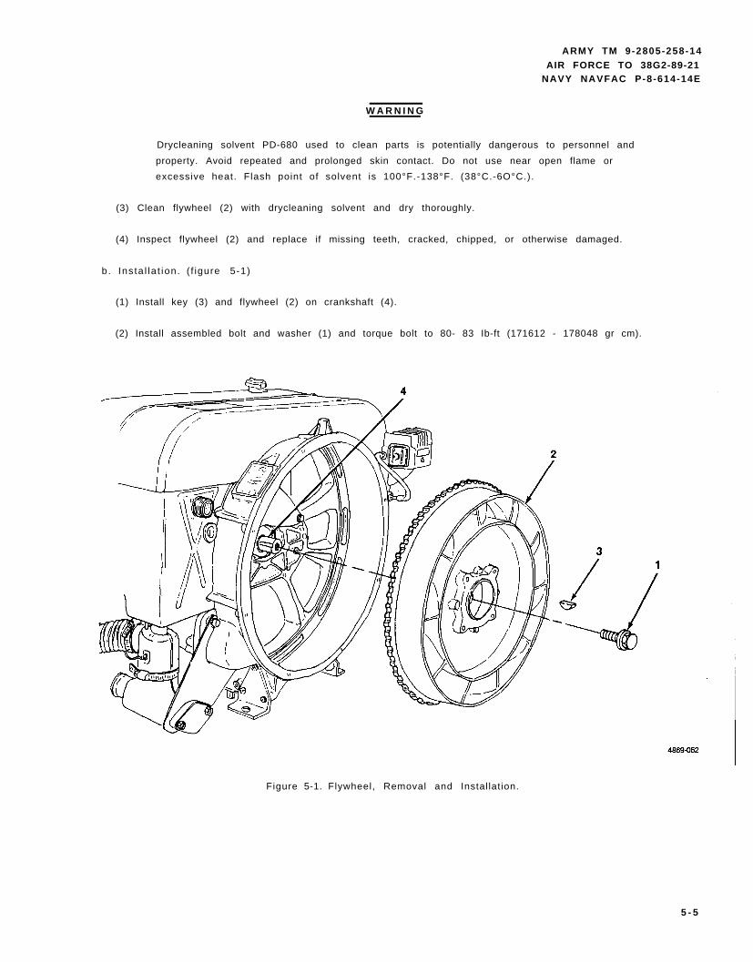
ARMY TM 9-2805-258-14AIR FORCE TO 38G2-89-21
NAVY NAVFAC P-8-614-14E
W A R N I N G
Drycleaning solvent PD-680 used to clean parts is potentially dangerous to personnel and
property. Avoid repeated and prolonged skin contact. Do not use near open flame or
excessive heat. Flash point of solvent is 100°F.-138°F. (38°C.-6O°C.).
(3) Clean flywheel (2) with drycleaning solvent and dry thoroughly.
(4) Inspect flywheel (2) and replace if missing teeth, cracked, chipped, or otherwise damaged.
b. Ins ta l la t ion. ( f igure 5-1)
(1) Install key (3) and flywheel (2) on crankshaft (4).
(2) Install assembled bolt and washer (1) and torque bolt to 80- 83 Ib-ft (171612 - 178048 gr cm).
Figure 5-1. Flywheel, Removal and Installation.
5 - 5
ARMY TM 9-2805-258-14AIR FORCE TO 38G2-89-21NAVY NAVFAC P-8-614-14E
5-8. Fan Housing.
This task covers: a . Removal b. Installation
INITIAL SETUP
Tools Equipment Condi t ion
General Mechanic’s Tool Kit (Item 1, Appendix B) Flywheel removed (para. 5-7).
Regulator-rectif ier removed (para. 4-40).
Starter removed (para. 4-39).
a. R e m o v a l . ( f igure 5-2)
(1)
(2)
(3)
(4)
Remove two screws (1) and washers (2) securing oil pan shroud (3) to fan housing (4).
N O T E
The engine mounts, oil pan baffle and control rod are installed on flywheel fan housing
and do not have to be removed to remove fan housing assembly. Refer to unit
maintenance, Chapter 4 for removal and installation procedures for those items.
Remove six assembled screws and washers (5) and fan housing plate (6) and remove fan housing (4) .
Clean fan housing (4) with drycleaning solvent, and dry thoroughly.
Inspect fan housing (4) and replace if cracked or otherwise damaged,
b. Insta l la t ion. (figure 5-2)
(1) Install fan housing (4) and fan housing plate (6) and secure with six assembled screws and washers (5).
(2) Install two screws (1) and washers (2) and secure oil pan shroud (3) to fan housing (4).
5 - 6
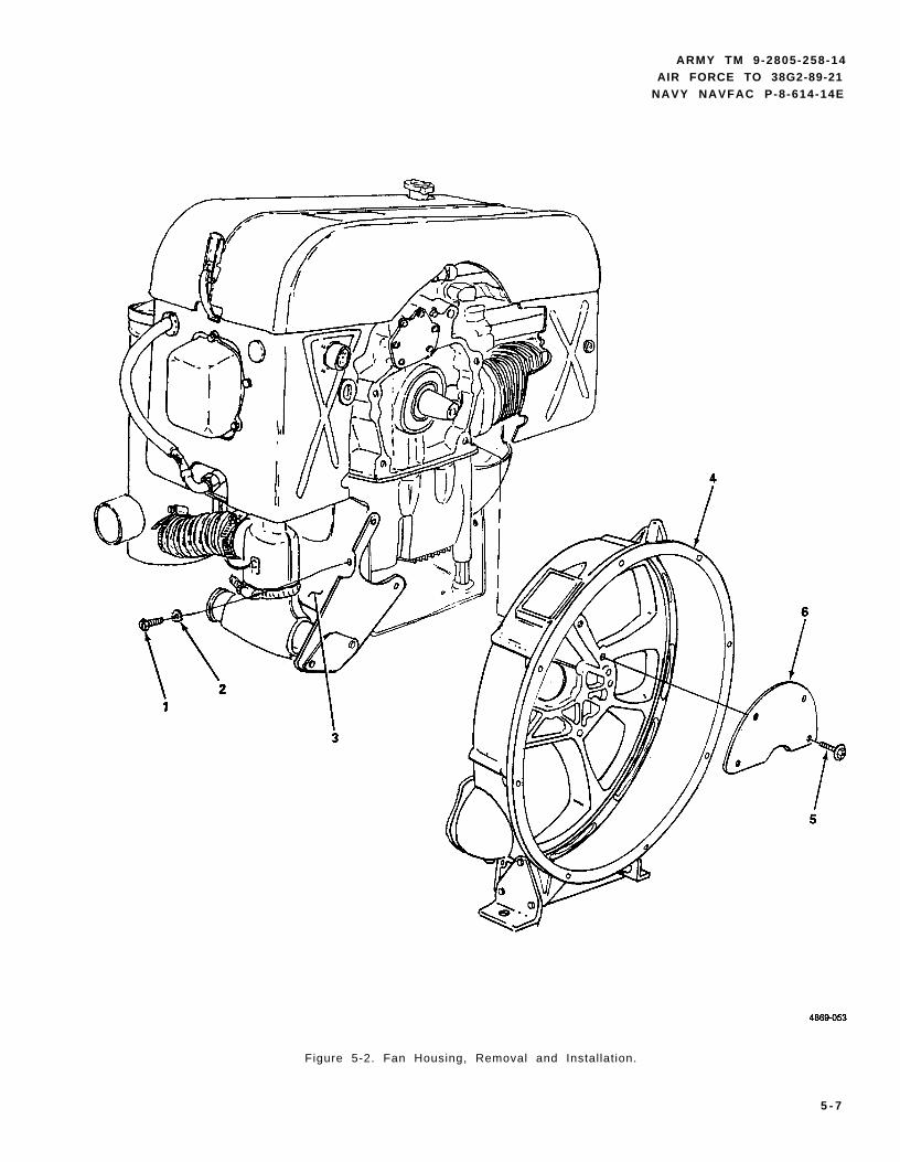
ARMY TM 9-2805-258-14AIR FORCE TO 38G2-89-21
NAVY NAVFAC P-8-614-14E
Figure 5-2. Fan Housing, Removal and Installation.
5 - 7
ARMY TM 9-2805-258-14AIR FORCE TO 38G2-89-21NAVY NAVFAC P-8-614-14E
5-9. Oil Pump Gears, Spacer and Oil Pump Cover.
This task covers: a . R e m o v a l b. Installation
INITIAL SETUP
Tools Equipment Condi t ion
General Mechanic’s Tool Kit (Item 1, Appendix B) Flywheel removed (para. 5-7).
Mater ia ls /Par ts
Rags, Wiping (Item 7, Appendix D)
Solvent, Drycleaning (Item 8, Appendix D)
Gasket, Oil Pump Cover Mounting
(P/N 13206E0717)
a. R e m o v a l . (figure 5-3)
(1) Remove four assembled screws and washers (1) and remove fan housing pIate (2).
(2) Remove seven nuts (3) and Iockwashers (4) and remove oil pump cover (5) and gasket (6).
(3) Remove two oil pump gears (7), key (8) and spacer (9).
W A R N I N G
Drycleaning solvent PD-680 used to clean parts is potentially dangerous to personnel and
property. Avoid repeated and prolonged skin contact. Do not use near open flame or
excessive heat. Flash point of solvent is 100°F.-138°F. (38°C.-60°C.).
(4) Clean all parts in drycleaning solvent, and dry thoroughly.
(5) Inspect gears (7) and spacer (9) and replace worn or otherwise damaged items. Refer to Table 5-2 for
wear l imits.
b. Insta l la t ion. (figure 5-3)
(1) Install spacer (9), key (8) and oil pump gears (7).
(2) Install oil pump cover (5) and gasket (6) and secure with seven nuts (3) and Iockwashers (4).
(3) Install fan housing plate (2) and secure with four assembled screws and washers (1).
5 - 8
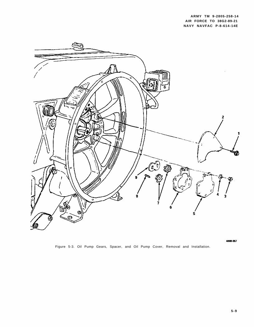
ARMY TM 9-2805-258-14AIR FORCE TO 38G2-89-21
NAVY NAVFAC P-8-614-14E
Figure 5-3. Oil Pump Gears, Spacer, and Oil Pump Cover, Removal and Installation.
5 - 9
ARMY TM 9-2805-258-14AIR FORCE TO 38G2-89-21NAVY NAVFAC P-8-614-14E
5-10. Oil Filler Tube and Gage.
This task covers: R e p l a c e m e n t
INITIAL SETUP
Tools Equipment Condi t ion
General Mechanic’s Tool Kit (Item 1, Appendix B) Top cover removed (para. 4-21).
R e p l a c e m e n t . (figure 5-4)
(1)
(2)
(3)
(4)
(5)
(6)
(7)
5 - 1 0
Remove nut (1), Iockwasher (2), and screw (3) and move filler tube bracket (4) away from governor
housing (5).
Remove two nuts (6), Iockwashers (7) and screws (8) and remove retaining straps (9) and filler tube
bracket (4) from oil filler tube (10).
Remove gage (11) from oil filler tube (10).
Gently tap oil filler tube (10) with mallet from side to side and remove.
N O T E
Do not use a hammer to install oil filler tube.
Position oil filler tube (10) and tap gently with mallet from top to install.
Install retaining straps (9) and filler tube bracket (4) and secure with two screws (8), washers (7), and
nuts (6).
Aline filler tube bracket (4) with governor housing (5) and secure with screw (3), Iockwasher (2), and
nut (1).
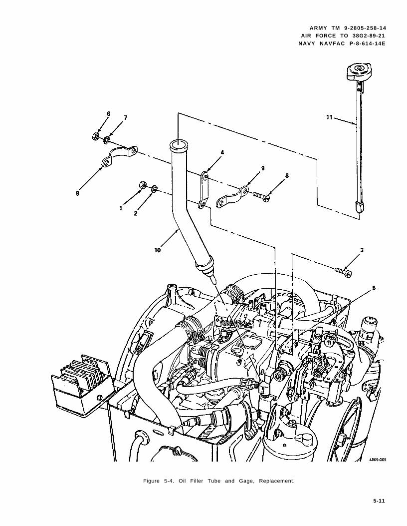
ARMY TM 9-2805-258-14AIR FORCE TO 38G2-89-21
NAVY NAVFAC P-8-614-14E
Figure 5-4. Oil Filler Tube and Gage, Replacement.
5-11
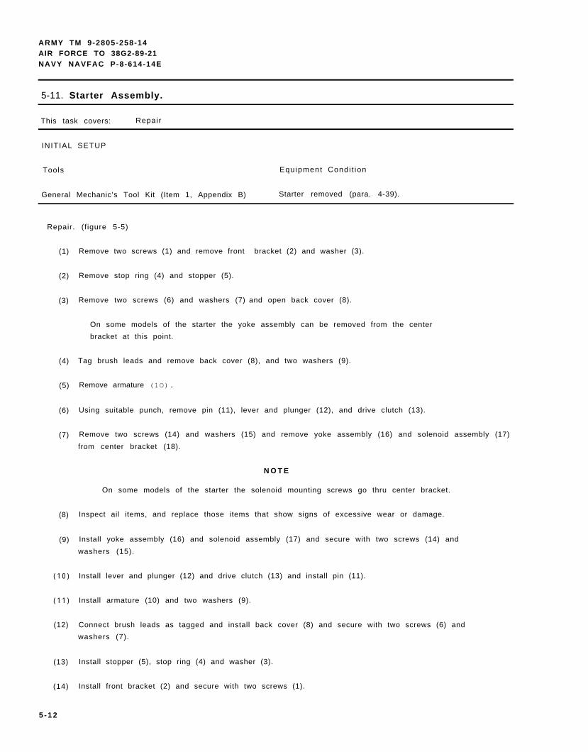
ARMY TM 9-2805-258-14AIR FORCE TO 38G2-89-21NAVY NAVFAC P-8-614-14E
5-11. Starter Assembly.
This task covers: Repair
INITIAL SETUP
Tools Equipment Condi t ion
General Mechanic’s Tool Kit (Item 1, Appendix B) Starter removed (para. 4-39).
Repair. (f igure 5-5)
(1)
(2)
(3)
(4)
(5)
(6)
(7)
(8)
(9)
( 1 0 )
( 1 1 )
(12)
(13)
(14)
5 - 1 2
Remove two screws (1) and remove front bracket (2) and washer (3).
Remove stop ring (4) and stopper (5).
Remove two screws (6) and washers (7) and open back cover (8).
On some models of the starter the yoke assembly can be removed from the center
bracket at this point.
Tag brush leads and remove back cover (8), and two washers (9).
Remove armature (1O).
Using suitable punch, remove pin (11), lever and plunger (12), and drive clutch (13).
Remove two screws (14) and washers (15) and remove yoke assembly (16) and solenoid assembly (17)
from center bracket (18).
N O T E
On some models of the starter the solenoid mounting screws go thru center bracket.
Inspect ail items, and replace those items that show signs of excessive wear or damage.
Install yoke assembly (16) and solenoid assembly (17) and secure with two screws (14) and
washers (15).
Install lever and plunger (12) and drive clutch (13) and install pin (11).
Install armature (10) and two washers (9).
Connect brush leads as tagged and install back cover (8) and secure with two screws (6) and
washers (7).
Install stopper (5), stop ring (4) and washer (3).
Install front bracket (2) and secure with two screws (1).
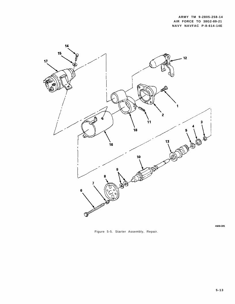
ARMY TM 9-2805-258-14AIR FORCE TO 38G2-89-21
NAVY NAVFAC P-8-614-14E
Figure 5-5. Starter Assembly, Repair.
5 - 1 3
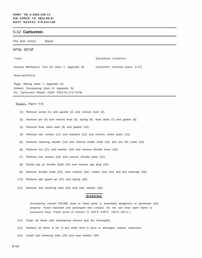
ARMY TM 9-2805-258-14AIR FORCE TO 38G2-89-21NAVY NAVFAC P-8-614-14E
5-12. Carburetor.
This task covers: Repair
INTIAL SETUP
Tools Equipment Condi t ion
General Mechanic’s Tool Kit (Item 1, Appendix B) Carburetor removed (para. 4-47).
Mater ia ls /Par ts
Rags, Wiping (Item 7, Appendix D)
Solvent, Drycleaning (Item 8, Appendix D)
Kit, Carburetor Repair (NSN 2910-01-273-7378)
R e p a i r . (figure 5-6)
(1)
(2)
(3)
(4)
(5)
(6)
(7)
(8)
(9)
( 1 0 )
(11)
(12)
(13)
(14)
Remove screw (1) and gasket (2) and remove bowl (3).
Remove pin (4) and remove float (5), spring (6), float valve (7) and gasket (8).
Remove float valve seat (9) and gasket (10).
Remove two screws (11) and washers (12) and remove choke plate (13).
Remove retaining washer (14) and remove choke shaft (15) and two felt seals (16).
Remove nut (17) and washer (18) and remove throttle lever (19).
Remove two screws (20) and remove throttle plate (21).
Gently tap on throttle shaft (22) and remove cap plug (23).
Remove throttle shaft (22), seal retainer (24), rubber seal (25) and two bearings (26).
Remove idle speed jet (27) and spring (28).
Remove fuel metering tube (29) and seal washer (30).
W A R N I N G
Drycleaning solvent PD-680 used to clean parts is potentially dangerous to personnel and
property. Avoid repeated and prolonged skin contact. Do not use near open flame or
excessive heat. Flash point of solvent is 100°F.-138°F. (38°C.-6O°C.).
Clean all items with drycleaning solvent and dry thoroughly.
Replace all items in kit. If any other item is worn or damaged, replace carburetor.
Install fuel metering tube (29) and seal washer (30).
5 - 1 4
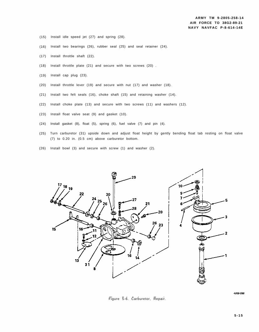
(15)
(16)
(17)
(18)
(19)
(20)
(21)
(22)
(23)
(24)
(25)
(26)
ARMY TM 9-2805-258-14AIR FORCE TO 38G2-89-21
NAVY NAVFAC P-8-614-14E
Install idle speed jet (27) and spring (28).
Install two bearings (26), rubber seal (25) and seal retainer (24).
Install throttle shaft (22).
Install throttle plate (21) and secure with two screws (20) .
Install cap plug (23).
Install throttle lever (19) and secure with nut (17) and washer (18).
Install two felt seals (16), choke shaft (15) and retaining washer (14).
Install choke plate (13) and secure with two screws (11) and washers (12).
Install float valve seat (9) and gasket (10).
Install gasket (8), float (5), spring (6), fuel valve (7) and pin (4).
Turn carburetor (31) upside down and adjust float height by gently bending float tab resting on float valve
(7) to 0.20 in. (0.5 cm) above carburetor bottom.
Install bowl (3) and secure with screw (1) and washer (2).
Figure 5-6. Carburetor, Repair.
5 - 1 5
ARMY TM 9-2805-258-14
AIR FORCE TO 38G2-89-21
NAVY NAVFAC P-8-614-14E
5-13. Timing Gear Cover.
This task covers: a . R e m o v a l b. Installation
INITIAL SETUP
Tools Equipment Condi t ion
General Mechanic’s Tool Kit (Item 1, Appendix B) Governor removed (para. 4-44) .
Magneto removed (para. 4-32).
Mater ia ls /Par ts Alternator removed (para. 4-52).
Breather tube removed (para. 4-18).
Rags, Wiping (Item 7, Appendix D)
Solvent, Drycleaning (Item 8, Appendix D)
Gasket, Timing Gear Cover Mounting
P/N 13206E0582)
a. R e m o v a l (f igure 5 - 7 )
(1) Tag and disconnect wiring from oil pressure transmitter (1).
(2) Loosen fitting nut (2) and tag and remove oil line (3).
(3) Loosen fitting nut (4) and tag and remove oil line (5).
(4) Remove screw (6), washer (7), and nut (8) securing oil filler tube bracket (9).
(5) Remove assembled screw and washer (10).
(6) Remove eight assembled screws and washers (11) and remove timing gear cover (12) and gasket (13).
W A R N I N G
Drycleaning solvent P-D-680, or P-S-661, used to clean parts is potentially dangerous to
personnel and properly. Avoid repeated and prolonged skin contact. Do not use near
open flame or excessive heat. Flash point of solvent is 100°F.-138°F. (38°C.-6O°C.).
(7) Clean timing gear cover (12) with drycleaning solvent, and dry thoroughly.
N O T E
If timing gear cover is replaced, oil pressure transmitter, studs, tachometer adapter, air
breather reed and support must be transferred to new timing gear cover.
(8) Inspect timing gear cover (12) and replace cover if cracked or otherwise damaged.
(9) Inspect oil seal (14) and replace if torn or otherwise damaged. (See para. 5-14.)
5 - 1 6
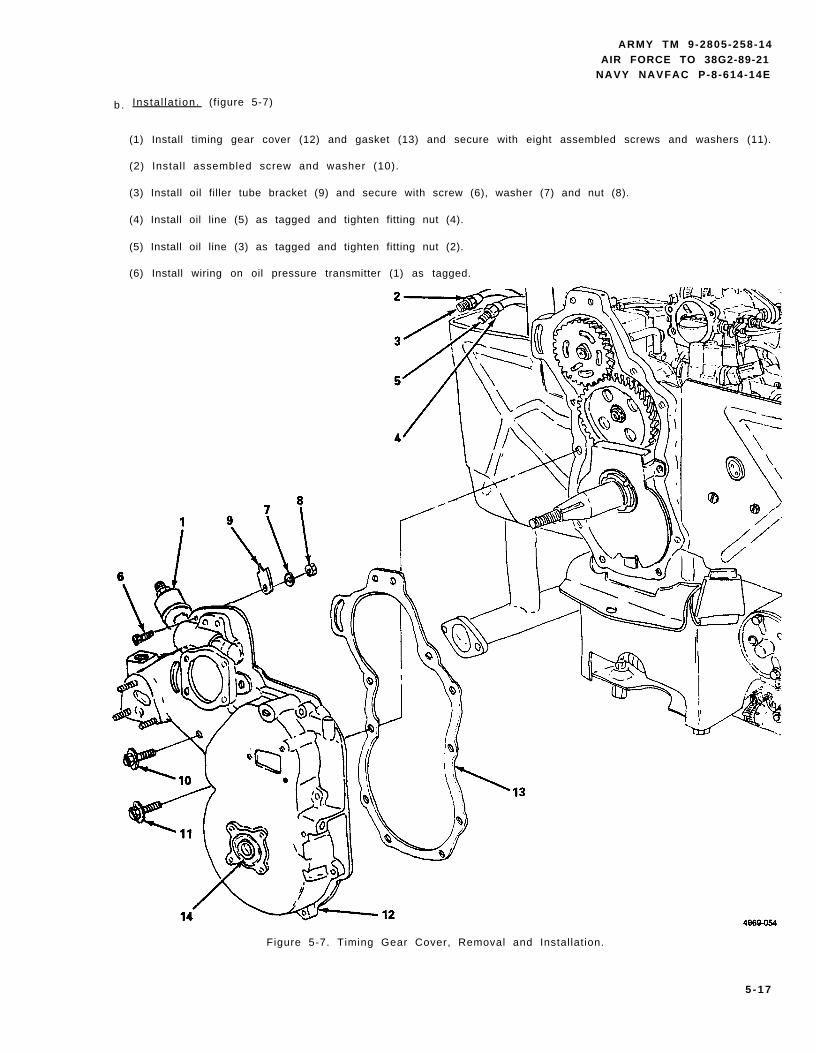
ARMY TM 9-2805-258-14AIR FORCE TO 38G2-89-21
NAVY NAVFAC P-8-614-14E
b . Insta l la t ion. (figure 5-7)
(1) Install timing gear cover (12) and gasket (13) and secure with eight assembled screws and washers (11).
(2) Instal l assembled screw and washer (10).
(3) Install oil filler tube bracket (9) and secure with screw (6), washer (7) and nut (8).
(4) Install oil line (5) as tagged and tighten fitting nut (4).
(5) Install oil line (3) as tagged and tighten fitting nut (2).
(6) Install wiring on oil pressure transmitter (1) as tagged.
Figure 5-7. Timing Gear Cover, Removal and Installation.
5 - 1 7
ARMY TM 9-2805-258-14
AIR FORCE TO 38G2-89-21NAVY NAVFAC P-8-614-14E
5-14. Timing Gear Cover Oil Seal.
This task covers: Replacement
INITIAL SETUP
Tools Equipment Condi t ion
General Mechanic’s Tool Kit (Item 1, Appendix B) Alternator removed (para. 4-52).
Mater ia ls /Par ts
Seal, Timing Gear Cover (NSN 5330-01-174-8148)
R e p l a c e m e n t . (figure 5-8)
(1) Remove all dirt and debris from around oil seal (1).
(2) Remove oil seal (1) from timing gear cover (2).
(3) Clean oil seal mounting surfaces.
N O T E
Do not use a hammer to install oil seal.
(4) Install oil seal (1) in timing gear cover (2).
5 - 1 8
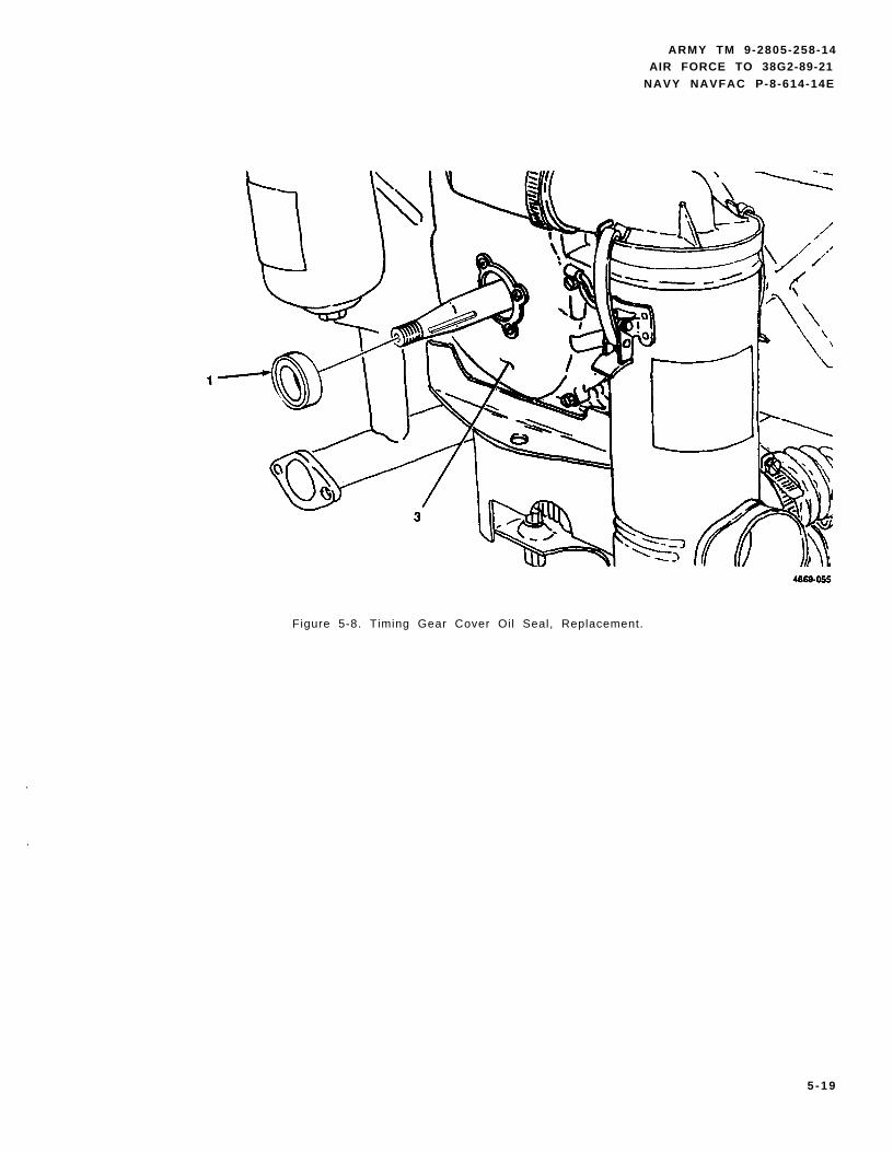
ARMY TM 9-2805-258-14AIR FORCE TO 38G2-89-21
NAVY NAVFAC P-8-614-14E
Figure 5-8. Timing Gear Cover Oil Seal, Replacement.
.
.
5 - 1 9
ARMY TM 9-2805-258-14
AIR FORCE TO 38G2-89-21NAVY NAVFAC P-8-614-14E
5-15. Oil Pan.
This task covers: a . R e m o v a l b. Installation
INITIAL SETUP
Tools Mater ia ls /Par ts
General Mechanic’s Tool Kit (Item 1, Appendix B) Rags, Wiping (Item 7, Appendix D)
Wrench, Torque (NSN 5120-00-853-4538) Solvent, Drycleaning (Item 8, Appendix D)
(Item 6, Appendix B) Gasket, Oil Pan Mounting (NSN 5330-00-073-3042)
Equipment Condi t ion:
Oil pan cover and shroud removed (para. 4-22).
a. R e m o v a l . ( f igure 5-9)
(1)
(2)
(3)
(4)
(5)
(6)
(7)
(8)
Remove either drain plug (1) or (2) and drain oil into suitable container.
Remove seven assembled screws and washers (3) and remove oil pan
Remove four special studs (7).
(4), gasket (5) and gasket (6).
W A R N I N G
Drycleaning solvent PD-680 used to clean parts is potentially dangerous to personnel and
property. Avoid repeated and prolonged skin contact. Do not use near open flame or
excessive heat. Flash point of solvent is 100°F.-138°F. (38°C.-60°C.).
Clean oil pan (4) with drycleaning solvent and dry thoroughly.
Inspect oil pan (4) and replace if cracked or otherwise damaged.
Remove, inspect and clean drain plugs (1) and (2) and gaskets (8) and replace as needed.
Inspect gasket (6) and replace if ripped or otherwise damaged.
Inspect special studs (7) and replace if damaged.
b . I n s t a l l a t i o n . ( f igure 5-9)
(1)
(2)
(3)
5 - 2 0
Ensure gasket mating surfaces are clean and old gasket material is removed.
Install oil pan (4), O-ring (6), and gasket (5) and secure with seven assembled screws and washers (3).
Torque screws to 25-30 lb-in. (4469 - 5363 gr cm).
Install drain plugs (1) and (2) and gaskets (8).
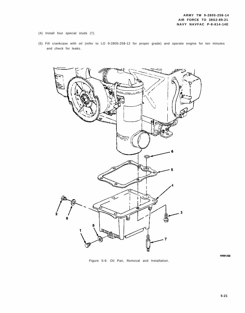
ARMY TM 9-2805-258-14AIR FORCE TO 38G2-89-21
NAVY NAVFAC P-8-614-14E
(4) Install four special studs (7).
(5) Fill crankcase with oil (refer to LO 9-2805-258-12 for proper grade) and operate engine for ten minutes
and check for leaks.
Figure 5-9. Oil Pan, Removal and Installation.
5-21
ARMY TM 9-2805-258-14AIR FORCE TO 38G2-89-21NAVY NAVFAC P-8-614-14E
5-16. Check Valve.
This task covers: a . R e m o v a l b. Installation
INITIAL SETUP
Tools Materials/Parts (cent)
General Mechanic’s Tool Kit (Item 5, Appendix B) Gasket, Check Valve Body (NSN 5330-00-867-8814)
Gasket, Check Valve Body Cover
Mater ia ls /Par ts (NSN 5330-00-867-8817)
Rags, Wiping (Item 7, Appendix D) Equipment Condi t ion
Solvent, Drycleaning (Item 8, Appendix D)
Oil pan removed (para. 5-15)
a. Removal . ( f igure 5-10)
(1)
(2)
(3)
(4)
(5)
Remove two assembled screws and washers (1).
Remove assembled screw and washer (2) and remove check valve assembly (3) and gasket (4) and
screen (5).
N O T E
The check valve cover holds down the spring, keep pressure on cover until both screws
are removed, then slowly remove cover.
Carefully remove two assembled screws and washers (6) and remove check valve cover (7), gasket (8),
spring (9), retainer (10), and disc (11).
W A R N I N G
Drycleaning solvent PD-680 used to clean parts is potentially dangerous to personnel and
property. Avoid repeated and prolonged skin contact. Do not use near open flame or
excessive heat. Flash point of solvent is 100°F.-138°F. (38°C.-6O°C.).
Clean all components in drycleaning solvent and dry thoroughly.
Inspect all components and replace those that are worn or otherwise damaged.
b. Insta l la t ion. (figure 5-10)
(1)
(2)
5 - 2 2
Ensure all gasket mating surfaces are clean and old gasket material is removed.
Install disc (11 ), retainer (10), spring (9), gasket (8), and cover (7), and secure with two assembled
screws and washers (6).
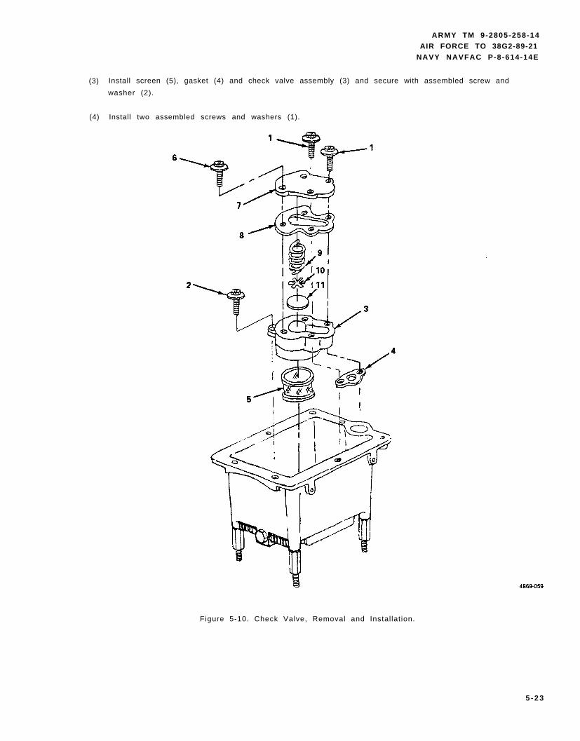
(3)
(4)
ARMY TM 9-2805-258-14AIR FORCE TO 38G2-89-21
NAVY NAVFAC P-8-614-14E
Install screen (5), gasket (4) and check valve assembly (3) and secure with assembled screw and
washer (2).
Install two assembled screws and washers (1).
Figure 5-10. Check Valve, Removal and Installation.
5 - 2 3
ARMY TM 9-2805-258-14
AIR FORCE TO 38G2-89-21NAVY NAVFAC P-8-614-14E
5-17. Cylinder Head Assembly.
This task covers: a . Removal b. Repair c. Installation
INITIAL SETUP
Tools
General Mechanic’s Tool Kit (Item 1, Appendix B)
Compressor, Valve Spring (NSN 5130-00-096-6677)
(Item 4, Appendix B)
Wrench, Torque (NSN 5120-00-853-4538)
(Item 6, Appendix B)
Wrench, Torque (NSN 5120-00-640-6364)
(Item 6, Appendix B)
Mater ia ls /Par ts
Rags, Wiping (Item 7, Appendix D)
Solvent, Drycleaning (Item 8, Appendix D)
Materials/Parts (cont)
Gasket, Intake Manifold Mounting
(NSN 5330-00-017-8927)
Equipment Condi t ion
Rocker covers removed (para. 4-51).
Top cover, left and right shrouds removed (para. 4-21).
Exhaust manifold removed (para. 4-45).
Spark plugs removed (para. 4-38).
Rockers removed (para. 5-17).
N O T E
This engine is equipped with two cylinder head assemblies. The following maintenance
procedures are the same for both.
a. R e m o v a l . (f igure 5 - 1 1 )
(1)
(2)
(3)
(4)
(5)
(6)
(7)
5 - 2 4
N O T E
Older engine models have a spring located under rocker shaft. Remove and discard the
spring, and replace it with retainer plate. Refer to TM 5-2805-258-24P.
Remove two nuts (1) and remove rocker assembly (2) and sleeve bushings (3).
Remove two spring clamps (4) and remove retainer plate (5).
Remove pushrods (6), pushrod housings (7), and preformed packings (8).
Remove two assembled screws and washers (9) securing intake manifold (10) and gasket (11) to
cylinder head (12).
Disconnect rocker box hose (13) from cylinder head (12).
Remove rubber access plug (14).
Remove four nuts (15) and washers (16) and remove cylinder head (12).
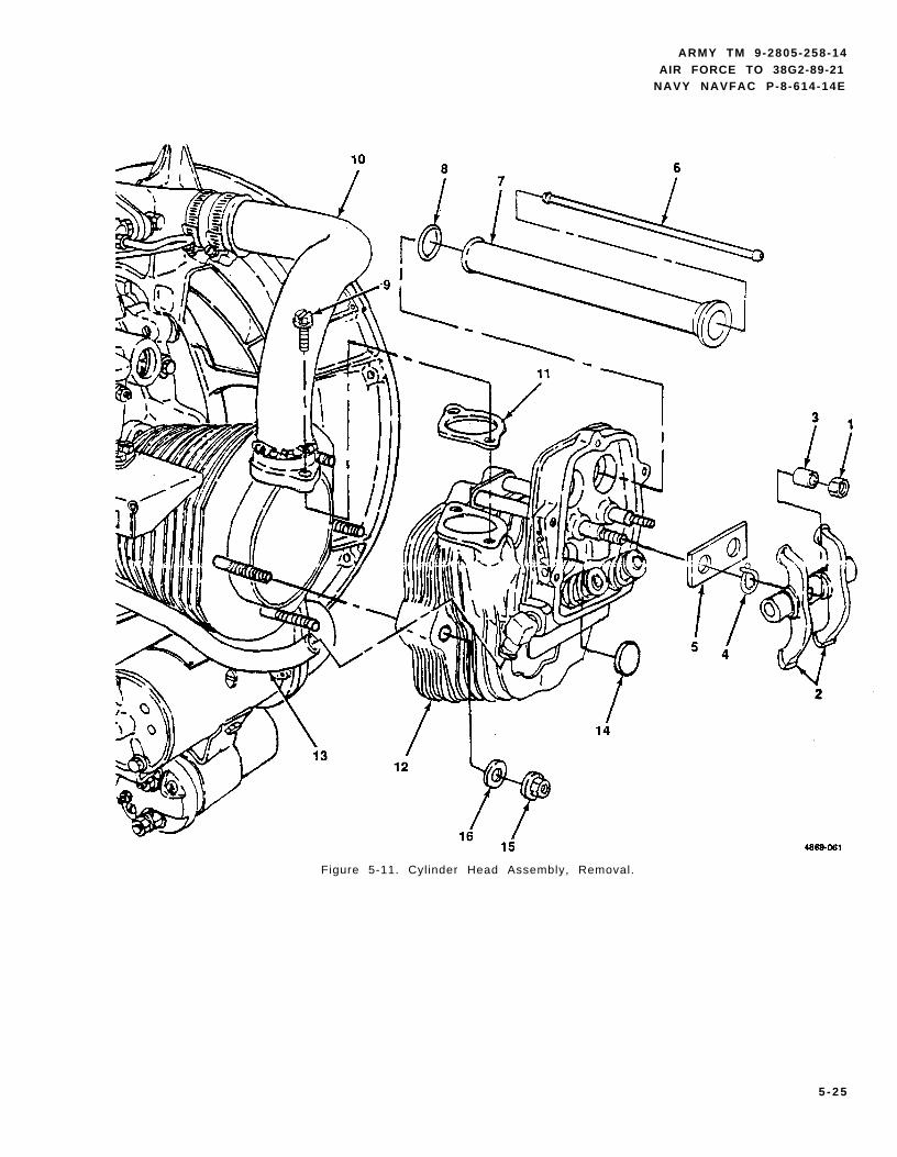
ARMY TM 9-2805-258-14AIR FORCE TO 38G2-89-21
NAVY NAVFAC P-8-614-14E
Figure 5-11. Cylinder Head Assembly, Removal.
5 - 2 5
ARMY TM 9-2805-258-14
AIR FORCE TO 38G2-89-21NAVY NAVFAC P-8-614-14E
5-17. Cylinder Head Assembly (cont).
b. R e p a i r . ( f igure 5-12)
(1)
(2)
(3)
(4)
(5)
(6)
(7)
(8)
(9)
( 1 0 )
( 1 1 )
(12)
(13)
(14)
5 - 2 6
Remove washer (1), rocker (2), washer (3) and retaining ring (4) from rocker shaft (5).
Remove retaining ring (6), washer (7), rocker (8) and washer (9) from rocker shaft (5).
Using suitable valve spring compressor, compress valve spring (10) and remove two retainers (11), roto
cap (12), valve spring (10), valve (13) and seal (14).
Repeat steps 1 through 3 for remaining valve.
Remove rocker shaft supports (15), seals (16) and rocker shaft plate (17).
W A R N I N G
Drycleaning solvent PD-680 used to clean parts is potentially dangerous to personnel and
property, Avoid repeated and prolonged skin contact. Do not use near open flame or
excessive heat. Flash point of solvent is 100°F.-138°F. (38°C.-8O°C.).
Clean all items, except seals, in drycleaning solvent, and diy thoroughly.
Inspect all items and replace if worn or otherwise damaged. Refer to Table 5-2 for wear limits.
Reseat valves in cylinder head (18).
Install rocker shaft plate (17), seals (16) and rocker shaft supports (15).
Install valve (13), seal (14), spring (10) and roto cap (12).
Using valve spring compressor, compress valve spring (10) and install two retainers (11).
Repeat step 10 and 11 for remaining valve.
Install washer (9), rocker (8), washer (7) and retaining ring (6).
Install retaining ring (4), washer (3), rocker (2) and washer (1).
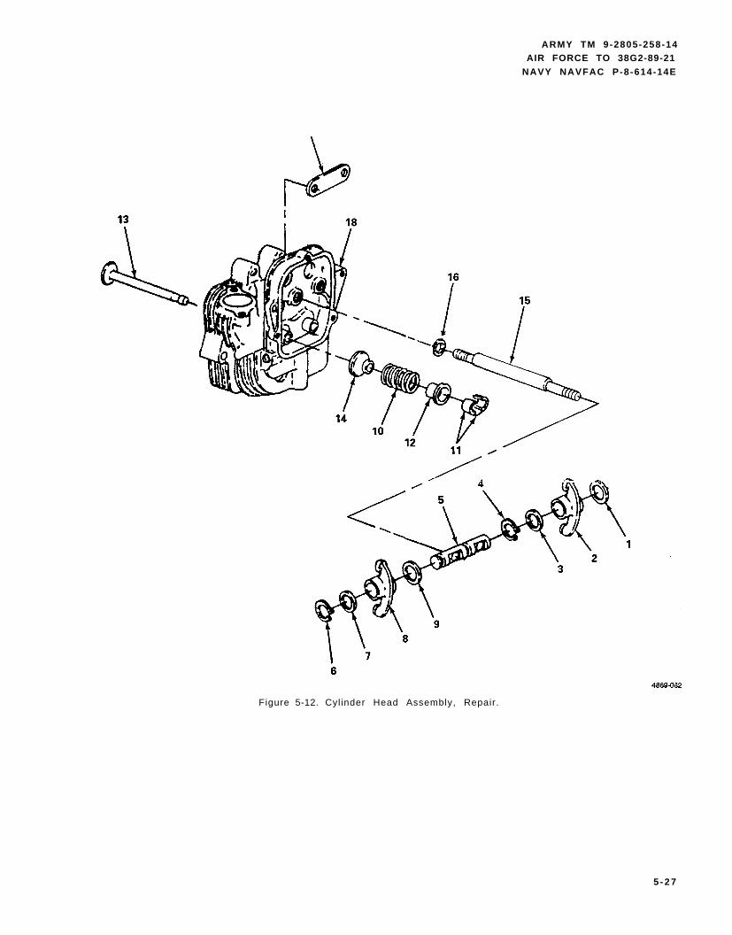
ARMY TM 9-2805-258-14AIR FORCE TO 38G2-89-21
NAVY NAVFAC P-8-614-14E
Figure 5-12. Cylinder Head Assembly, Repair.
5 - 2 7
ARMY TM 9-2805-258-14
AIR FORCE TO 38G2-89-21NAVY NAVFAC P-8-614-14E
5-17. Cylinder Head Assembly (cont).
c. Insta l la t ion. (figure 5-13)
(1)
(2)
(3)
(4)
(5)
(6)
(7)
(8)
(9)
(10)
5 - 2 8
Ensure gasket mating surfaces are clean, and old gasket material is removed.
Install preformed packings (8).
Install cylinder head (12), and secure with four nuts (15) and washers (16). Torque nuts to 22-24 Ib-ft
(47193 -51484 gr cm).
Install pushrod housings (7) through head (12) into crankcase.
Install pushrods (6).
Install retainer plate (5) and secure with two spring clamps (4).
Position rockers (2) and bushings (3) on pushrods (6) and tighten nuts (1). Torque nuts to 72-86 in.-lb
(12870 -15373 gr cm).
Install access plug (14).
Install rocker box hose (13).
Position intake manifold (10) and gasket (11) and secure with two assembled screws and washers (9).
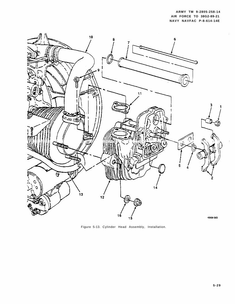
ARMY TM 9-2805-258-14AIR FORCE TO 38G2-89-21
NAVY NAVFAC P-8-614-14E
Figure 5-13. Cylinder Head Assembly, Installation.
5 - 2 9
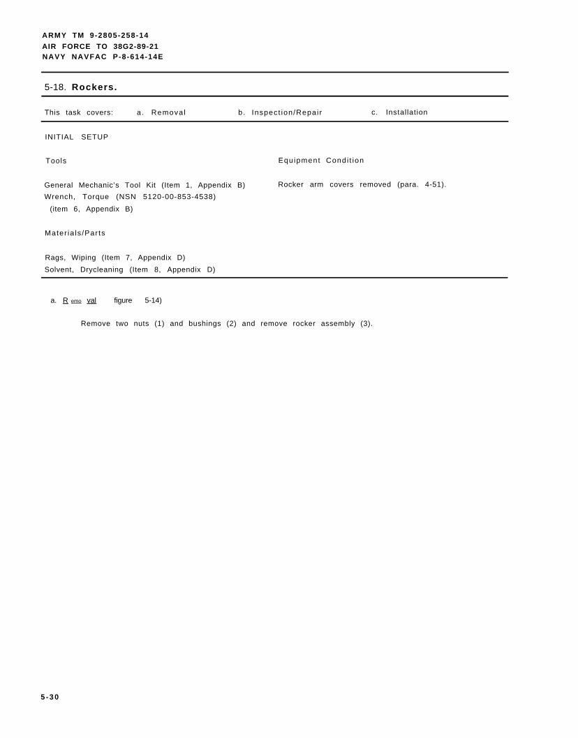
ARMY TM 9-2805-258-14
AIR FORCE TO 38G2-89-21NAVY NAVFAC P-8-614-14E
5-18. Rockers.
This task covers: a . Removal b. Inspect ion/Repai r c. Installation
INITIAL SETUP
Tools Equipment Condi t ion
General Mechanic’s Tool Kit (Item 1, Appendix B) Rocker arm covers removed (para. 4-51).
Wrench, Torque (NSN 5120-00-853-4538)
(item 6, Appendix B)
Mater ia ls /Par ts
Rags, Wiping (Item 7, Appendix D)
Solvent, Drycleaning (Item 8, Appendix D)
a. R emo val figure 5-14)
Remove two nuts (1) and bushings (2) and remove rocker assembly (3).
5 - 3 0
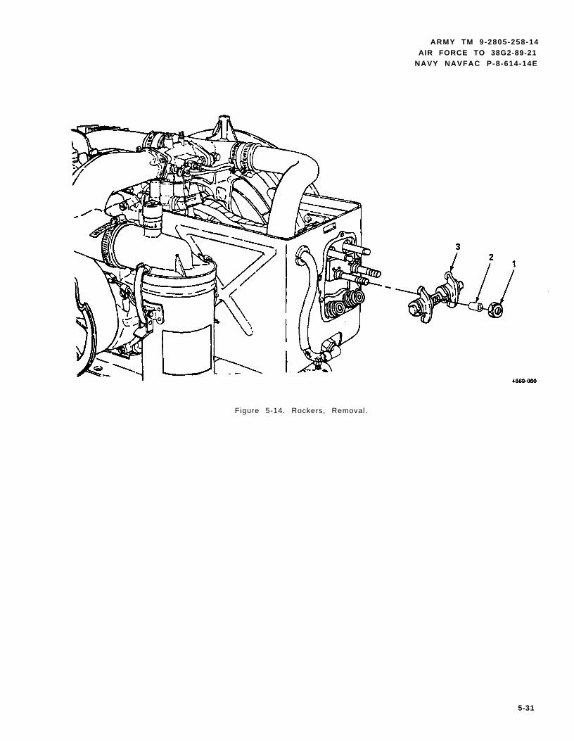
ARMY TM 9-2805-258-14AIR FORCE TO 38G2-89-21
NAVY NAVFAC P-8-614-14E
Figure 5-14. Rockers, Removal.
5-31
ARMY TM 9-2805-258-14AIR FORCE TO 38G2-89-21NAVY NAVFAC P-8-614-14E
5-I8. Rockers (cont).
b. I n s p e c t i o n / R e p a i r . ( f i g u r e 5 - 1 5 )
(1) Remove retaining ring (1), washer (2), rocker (3), and washer (4) from rocker shaft (5).
(2) Remove washer (6), rocker (7), washer (8), and retaining ring (9) from rocker shaft (5).
W A R N I N G
Drycleaning solvent PD-680 used to clean parts is potentially dangerous to personnel and
property. Avoid repeated and prolonged skin contact. Do not use near open flame or
excessive heat. Flash point of solvent is 100°F.-138°F. (38°C.–60°C.).
(3) Clean all items with drycleaning solvent and dry thoroughly.
(4) Inspect all items and replace all items that are worn or otherwise damaged. Refer to Table 5-2 for wear
limits.
(5) Install retaining ring (9), washer (8), rocker (7), and washer (6) on rocker shaft (5).
(6) Install washer (4), rocker (3), washer (2), and retaining ring (1) on rocker shaft (5).
Figure 5-15. Rockers, Inspection/Repair.
5 - 3 2
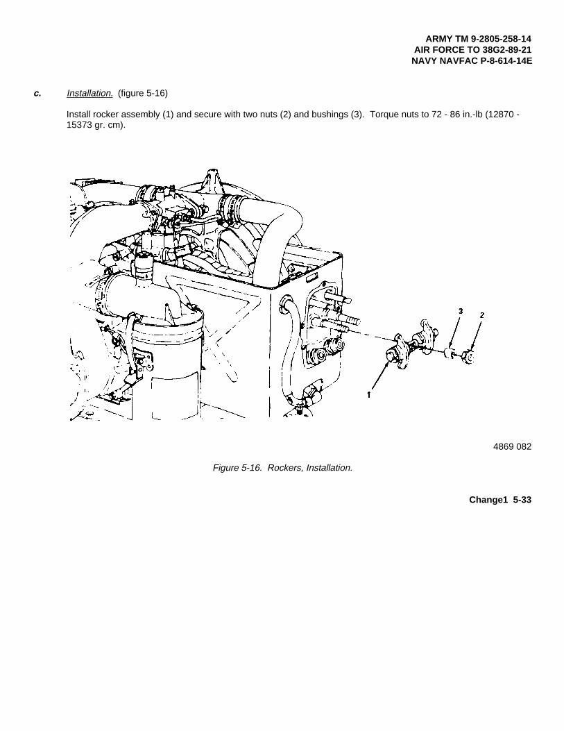
ARMY TM 9-2805-258-14AIR FORCE TO 38G2-89-21
NAVY NAVFAC P-8-614-14E
c. Installation. (figure 5-16)
Install rocker assembly (1) and secure with two nuts (2) and bushings (3). Torque nuts to 72 - 86 in.-lb (12870 -15373 gr. cm).
4869 082
Figure 5-16. Rockers, Installation.
Change1 5-33
ARMY TM 9-2805-258-14AIR FORCE TO 38G2-89-21NAVY NAVFAC P-8-614-14E
5-19. Intake and Exhaust Valves.
This task covers: a . Removal b. Installation
INITIAL SETUP
Tools Equipment Condi t ion
General Mechanic’s Tool Kit (Item 1, Appendix B) Cylinder head removed (para. 5-17).
Compressor, Valve Spring (NSN 5130-00-096-6677)
(Item 4, Appendix B)
Mater ia ls /Par ts
Rags, Wiping (Item 7, Appendix D)
Solvent, Drycleaning (Item 8, Appendix D)
N O T E
The following procedures are the same for both the intake and exhaust valves.
a. Removal . ( f igure 5-17)
(1) Using valve spring compressor, compress valve spring (1) and remove two retainers (2), roto cap (3),
spring (1), valve (4), and seal (5).
W A R N I N G
Drycleaning solvent PD-680 used to clean parts is potentially dangerous to personnel and
property. Avoid repeated and prolonged skin contact. Do not use near open flame or
excessive heat. Flash point of solvent is 100°F.-138°F. (38°C.-6O°C.).
(2) Clean all items with drycleaning solvent and dry thoroughly.
(3) Inspect all items and replace all worn or otherwise damaged components. Refer to Table 5-2 for wear
limits.
b. Insta l la t ion. (figure 5-17)
(1) Grind or seat valve (4) and install valve (4), seal (5), spring (1) and roto cap (3).
(2) Using valve spring compressor, compress valve spring (1) and install two retainers (2).
5 - 3 4
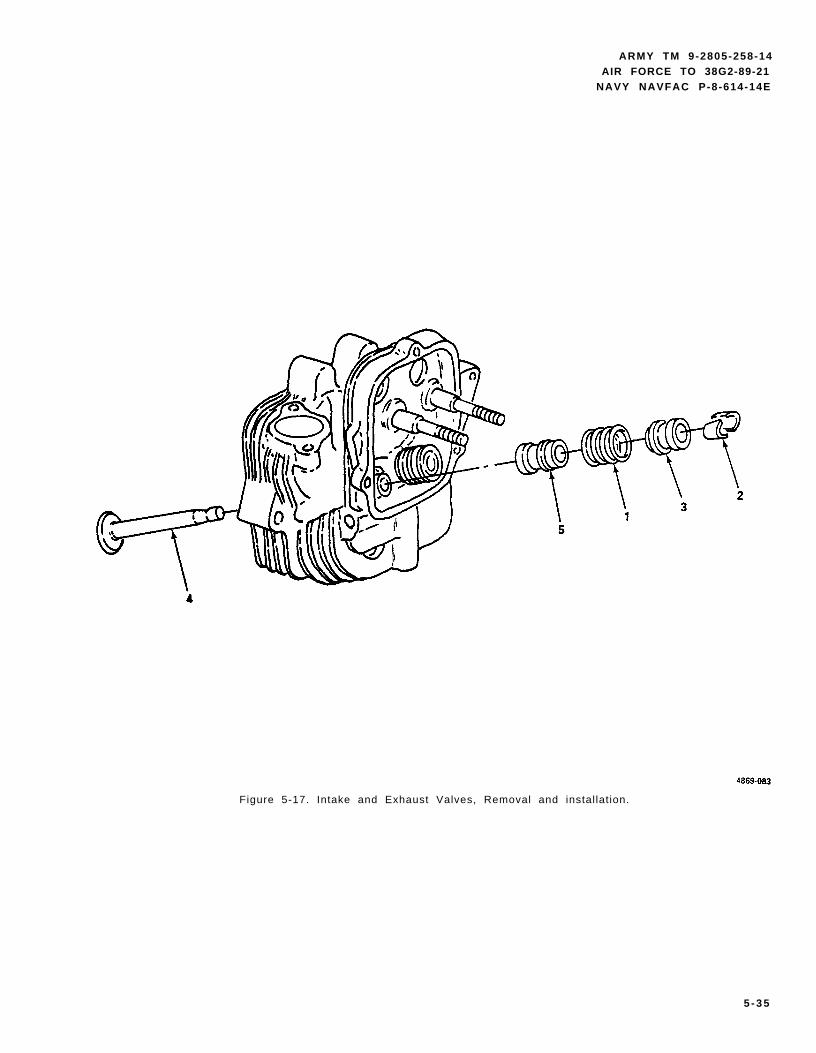
ARMY TM 9-2805-258-14AIR FORCE TO 38G2-89-21
NAVY NAVFAC P-8-614-14E
Figure 5-17. Intake and Exhaust Valves, Removal and installation.
5 - 3 5
ARMY TM 9-2805-258-14AIR FORCE TO 38G2-89-21NAVY NAVFAC P-8-614-14E
5-20. Valve Tappets.
This task covers: a . Removal b. Installation
INITIAL SETUP
Tools Equipment Condi t ion
General Mechanic’s Tool Kit (Item 1, Appendix B) Top cover removed (para. 4-21).
Rockers removed (para. 5-18)
Mater ia ls /Pads
Rags, Wiping (Item 7, Appendix D)
Solvent, Drycleaning (Item 8, Appendix D)
a. R e m o v a l ( f igure 5-18)
N O T E
The following procedures are the same for all valve tappets.
(1) Remove two spring spring clamps (1) and remove retainer plate (2).
(2) Remove pushrod (3) and pushrod housing (4).
(3) Remove preformed packing (5) and remove valve tappet (6).
W A R N I N G
Drycleaning solvent PD-680 used to clean parts is potentially dangerous to personnel and
property. Avoid repeated and prolonged skin contact. Do not use near open flame or
excessive heat. Flash point of solvent is 100°F.-138°F. (38°C.-6O°C.).
(4) Clean valve tappet (6) in drycleaning solvent and dry thoroughly.
(5) Inspect valve tappet (6) and replace if worn or otherwise damaged. Refer to Table 5-2 for wear limits.
b . Insta l la t ion. (figure 5-18)
(1) Install valve tappet (6) and preformed packing (5).
(2) Install pushrod housing (4) and pushrod (3).
(3) Install retainer plate (2) and secure with two spring clamps (1).
5 - 3 6
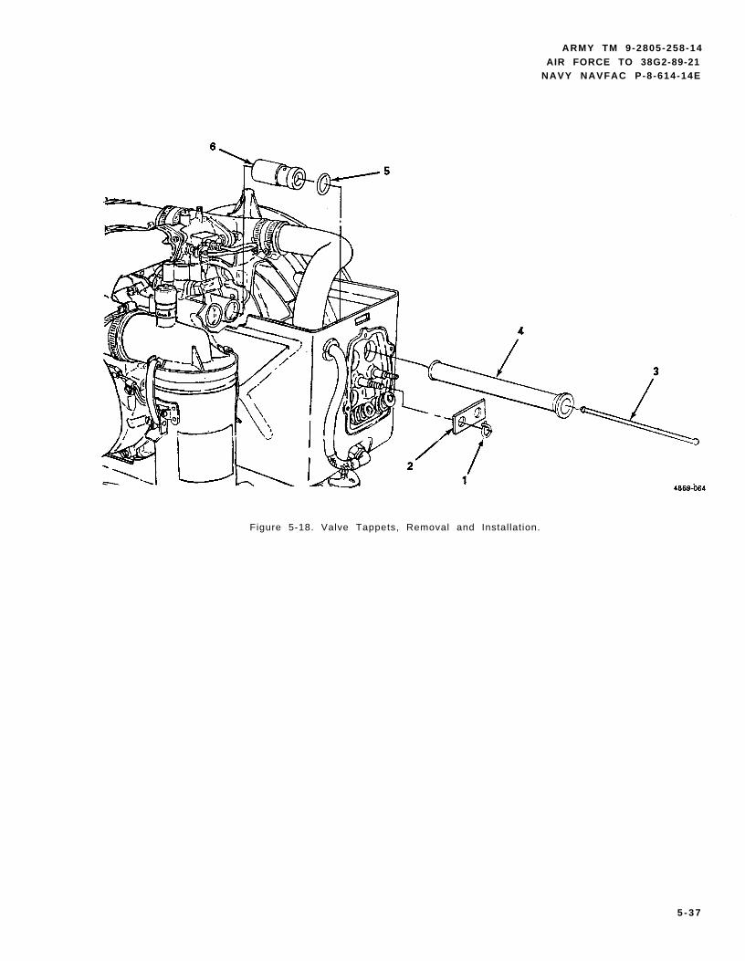
ARMY TM 9-2805-258-14AIR FORCE TO 38G2-89-21
NAVY NAVFAC P-8-614-14E
Figure 5-18. Valve Tappets, Removal and Installation.
5 - 3 7
ARMY TM 9-2805-258-14AIR FORCE TO 38G2-89-21NAVY NAVFAC P-8-614-14E
5-21. Rear Oil Seal.
This task covers: R e p l a c e m e n t
INITIAL SETUP
Tools Equipment Condi t ion
General Mechanic’s Tool Kit (Item 1, Appendix B) Flywheel removed (para. 5-7).
Seal Replacement Tool (NSN 5120-00-357-6917)
(Item 4, Appendix B)
Mater ia ls /Par ts
Seal, Rear Oil (NSN 5330-00-073-3014)
R e p l a c e m e n t . (figure 5 - 1 9 )
(1) Clean all dirt and debris from around rear oil seal.
(2) Remove rear oil seal (1).
(3) Clean oil seal mounting surfaces.
N O T E
Do not use a hammer to install oil seal.
(4) Using seal replacement tool install rear oil seal (1).
5 - 3 8
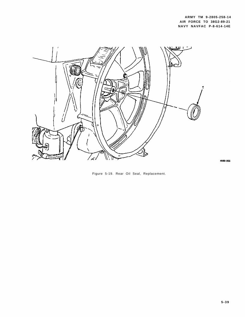
Figure 5-19. Rear Oil Seal, Replacement.
ARMY TM 9-2805-258-14AIR FORCE TO 38G2-89-21
NAVY NAVFAC P-8-614-14E
5 - 3 9
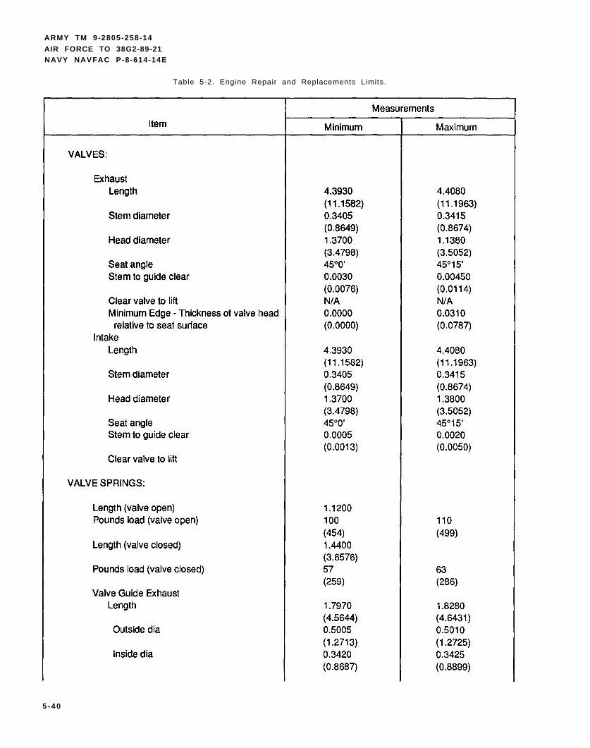
ARMY TM 9-2805-258-14
AIR FORCE TO 38G2-89-21NAVY NAVFAC P-8-614-14E
Table 5-2. Engine Repair and Replacements Limits.
5 - 4 0
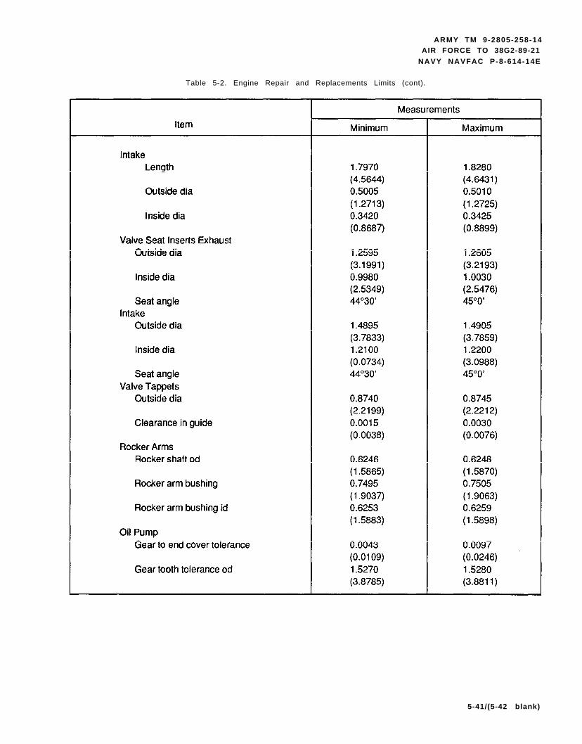
ARMY TM 9-2805-258-14AIR FORCE TO 38G2-89-21
NAVY NAVFAC P-8-614-14E
Table 5-2. Engine Repair and Replacements Limits (cont).
5-41/(5-42 blank)

ARMY TM 9-2805-258-14AIR FORCE TO 38G2-89-21
NAVY NAVFAC P-8-614-14E
CHAPTER 6
GENERAL SUPPORT MAINTENANCE INSTRUCTIONS
Sect ion P a g e
OVERVIEW . . . . . . . . . . . . . . . . . . . . . . . . . . . . . . . . . . . . . . . . . . . . . . . . . . . . . . . . . . . . . . . ...6-1
Section l. Repair Parts; Special Tools; Test, Measurement, Diagnostic
Equipment (TMDE);and Support Equipment . . . . . . . . . . . . . . . . . . . . . . . . . . . . . . 6-1
Section Il. General Support Troubleshooting . . . . . . . . . . . . . . . . . . . . . . . . . . . . . . . . . . . . ...6-1
Section ll l. General Support Maintenance Procedures . . . . . . . . . . . . . . . . . . . . . . . . . . . . . . . . 6-3
O V E R V I E W
This chapter provides procedures for troubleshooting and maintenance of the 10 HP Military Standard Engine by
General Support maintenance personnel.
Section l REPAIR PARTS; SPECIAL TOOLS; TEST, MEASUREMENT, DIAGNOSTIC
EQUIPMENT (TMDE); AND SUPPORT EQUIPMENT
Paragraph P a g e
6-1 Common Tools and Test Equipment . . . . . . . . . . . . . . . . . . . . . . . . . . . . . . . . . . . . . . ...6-1
6 - 2 Special Tools, TMDE, and Support Equipment . . . . . . . . . . . . . . . . . . . . . . . . . . . . . . . . . 6-1
6 - 3 Repair Parts . . . . . . . . . . . . . . . . . . . . . . . . . . . . . . . . . . . . . . . . . . . . . . . . . . . . . . . . . ...6-1
6-1. Common Tools and Equipment. For authorized common tools and equipment, refer to the Modified
Table of Organization and Equipment (MTOE) applicable to your unit.
6-2. Special Tools, TMDE and Support Equipment. For a listing of special tools, TMDE, and support
equipment authorized for use on this equipment, refer to the Repair Parts and Special Tools List, TM 5-2805-258-
24P, and the maintenance allocation chart (MAC), appendix B of this manual.
6-3. Repair Parts. Repair parts are listed and illustrated in the Repair Parts and Special Tools List for 10 HP
Military Standard Engine TM 5-2805-258-24P.
Section I l . GENERAL SUPPORT TROUBLESHOOTING
Paragraph P a g e
6 - 4 General . . . . . . . . . . . . . . . . . . . . . . . . . . . . . . . . . . . . . . . . . . . . . . . . . . . . . . . . . . . . ...6-1
6 - 5 General Support Troubleshooting Procedures . . . . . . . . . . . . . . . . . . . . . . . . . . . . . . . . . 6-2
6-4. General. This section contains troubleshooting procedures to determine the probable cause of observed
equipment malfunctions. Tests or inspections are provided to isolate the faulty component and corrective actions
are provided to eliminate the malfunction.
6-1
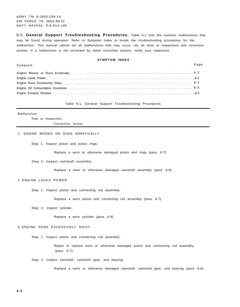
ARMY TM 9-2805-258-14
AIR FORCE TO 38G2-89-21NAVY NAVFAC P-8-614-14E
6-5. General Support Troubleshooting Procedures. Table 6-1 lists the common malfunctions that
may be found during operation. Refer to Symptom Index to locate the troubleshooting procedures for the
malfunction. This manual cannot list all malfunctions that may occur, nor all tests or inspections and corrective
actions. If a malfunction is not corrected by listed corrective actions, notify your supervisor.
S Y M P T O M I N D E X
S y m p t o m P a g e
Engine Misses or Runs Erratically . . . . . . . . . . . . . . . . . . . . . . . . . . . . . . . . . . . . . . . . . . . . . . . . . . . . . . 6 - 2
Engine Lacks Power . . . . . . . . . . . . . . . . . . . . . . . . . . . . . . . . . . . . . . . . . . . . . . . . . . . . . . . . . . . . . . ...6-2
Engine Runs Excessively Noisy . . . . . . . . . . . . . . . . . . . . . . . . . . . . . . . . . . . . . . . . . . . . . . . . . . . . . . . . 6 - 2
Engine Oil Consumption Excessive . . . . . . . . . . . . . . . . . . . . . . . . . . . . . . . . . . . . . . . . . . . . . . . . . . . . . 6 - 3
Engine Exhaust Smokey . . . . . . . . . . . . . . . . . . . . . . . . . . . . . . . . . . . . . . . . . . . . . . . . . . . . . . . . . . . ...6-3
Table 6-1. General Support Troubleshooting Procedures.
Mal funct ion
Test or Inspection
Corrective Action
1. ENGINE MISSES OR RUNS ERRATICALLY.
Step 1. Inspect piston and piston rings.
Replace a worn or otherwise damaged piston and rings (para. 6-7).
Step 2. Inspect camshaft assembly.
Replace a worn or otherwise damaged camshaft assembly (para. 6-9).
2. E N G I N E L A C K S P O W E R .
Step 1. Inspect piston and connecting rod assembly.
Replace a worn piston and connecting rod assembly (para. 6-7).
Step 2. Inspect cylinder.
Replace a worn cylinder (para. 6-8).
3. ENGINE RUNS EXCESSIVELY NOISY.
Step 1. Inspect piston and connecting rod assembly.
Repair or replace worn or otherwise damaged piston and connecting rod assembly
(para. 6-7).
Step 2. Inspect camshaft, camshaft gear, and bearing.
Replace a worn or otherwise damaged camshaft, camshaft gear, and bearing (para. 6-9).
6 - 2
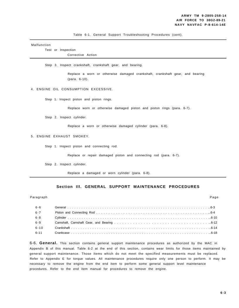
ARMY TM 9-2805-258-14AIR FORCE TO 38G2-89-21
NAVY NAVFAC P-8-614-14E
Table 6-1. General Support Troubleshooting Procedures (cent).
Mal funct ion
Test or Inspection
Corrective Action
Step 3. Inspect crankshaft, crankshaft gear, and bearing.
Replace a worn or otherwise damaged crankshaft, crankshaft gear, and bearing
(para. 6-10).
4 . ENGINE OIL CONSUMPTION EXCESSIVE.
Step 1. Inspect piston and piston rings.
Replace worn or otherwise damaged piston and piston rings (para. 6-7).
Step 2. Inspect cylinder.
Replace a worn or otherwise damaged cylinder (para. 6-8).
5 . ENGINE EXHAUST SMOKEY.
Step 1. Inspect piston and connecting rod.
Replace or repair damaged piston and connecting rod (para. 6-7).
Step 2. Inspect cylinder.
Replace a damaged or worn cylinder (para. 6-8).
Section I l l . GENERAL SUPPORT MAINTENANCE PROCEDURES
Paragraph P a g e
6 - 6 GeneraI . . . . . . . . . . . . . . . . . . . . . . . . . . . . . . . . . . . . . . . . . . . . . . . . . . . . . . . . . . . . ...6-3
6 - 7 Piston and Connecting Rod . . . . . . . . . . . . . . . . . . . . . . . . . . . . . . . . . . . . . . . . . . . . . ...6-4
6 - 8 Cylinder . . . . . . . . . . . . . . . . . . . . . . . . . . . . . . . . . . . . . . . . . . . . . . . . . . . . . . . . . . . . ...6-10
6 - 9 Camshaft, Camshaft Gear, and Bearing . . . . . . . . . . . . . . . . . . . . . . . . . . . . . . . . . . . ...6-12
6 - 1 0 Crankshaft . . . . . . . . . . . . . . . . . . . . . . . . . . . . . . . . . . . . . . . . . . . . . . . . . . . . . . . . . . ...6-14
6-11 Crankcase . . . . . . . . . . . . . . . . . . . . . . . . . . . . . . . . . . . . . . . . . . . . . . . . . . . . . . . . . . ...6-18
6-6. General. This section contains general support maintenance procedures as authorized by the MAC in
Appendix B of this manual. Table 6-2 at the end of this section, contains wear limits for those items maintained by
general support maintenance. Those items which do not meet the specif ied measurements must be replaced.
Refer to Appendix E for torque values. All maintenance procedures require only one person to perform. It may be
necessary to remove the engine from the end item to perform some general support level maintenance
procedures. Refer to the end item manual for procedures to remove the engine.
6 - 3
ARMY TM 9-2805-258-14AIR FORCE TO 38G2-89-21NAVY NAVFAC P-8-614-14E
6-7. Piston and Connecting Rod.
This task covers: a . Removal b. Repair c. Installation
INITIAL SETUP
Tools
General Mechanic’s Tool Kit (Item 1, Appendix B)
Wrench, Torque (NSN 5120-00-640-6364)
(Item 6, Appendix B)
Compressor, Piston Ring (NSN 5120-00-250-6055)
(Item 4, Appendix B)
Mater ia ls /Par ts
Rags, Wiping (Item 7, Appendix D)
Solvent, Drycleaning (Item 8, Appendix D)
Materials/Parts (cent)
Nuts, Lock (NSN 5310-00-917-6624)
Bolts (NSN 5306-00-073-3018)
Ring Retaining (NSN 5365-00-374-9707)
Parts Kit, Piston Ring (NSN 2805-00-073-3020)
Nuts (NSN 5310-00-917-6624)
Equipment Condi t ion
Cylinder head removed (para. 5-17).
Oil pan removed (para. 5-15).
N O T E
This engine has two pistons and connecting rods, the following procedures are the same
for both.
a. R e m o v a l . ( f igure 6-1)
(1) Remove all carbon deposits from top of piston (1) and cylinder (2).
(2) Remove two nuts (3) and remove connecting rod bearing cap (4) and bearings (5).
(3) Slide piston (1) with connecting rod (6) out of cylinder (2).
6 - 4

ARMY TM 9-2805-258-14AIR FORCE TO 38G2-89-21
NAVY NAVFAC P-8-614-14E
Figure 6-1. Piston and Connecting Rod, Removal.
6 - 5
R M Y T M 9 - 2 8 0 5 - 2 5 8 - 1 4AIR FORCE TO 38G2-89-21NAVY NAVFAC P-8-614-14E
6-7. Piston and Connecting Rod (cont).
N O T E
Do not reuse piston rings or retaining rings.
b. Repair. (figure 6-2)
(1)
(2)
(3)
(4)
(5)
(6)
(7)
(6)
(9)
Remove two retaining rings (1) and slide piston pin (2) out of piston (3) and connecting rod (4).
Remove spacer ring (5), compression ring (6), intermediate compression ring (7), oil ring (8) and
expander ring (9).
W A R N I N G
Drycleaning solvent PD-680 used to clean parts is potentially dangerous to personnel and
property. Avoid repeated and prolonged skin contact. Do not use near open flame or
excessive heat. Flash point of solvent is 100°F.-138°F. (38°C.-60°C.).
Clean all items in drycleaning solvent, and dry thoroughly.
N O T E
Connecting rod bushing must be pressed out to replace.
Inspect connecting rod bearing cap (10), connecting rod (4), bearings (11), and bushing (12). Refer to
Table 6-2 for wear limits. Replace all items that are worn or otherwise damaged.
Inspect bolt (13) and nut (14) and replace if threads are stripped or otherwise damaged.
Ensure piston ring grooves are clean, and all carbon deposits are removed.
Inspect piston (3) and replace a worn or otherwise damaged piston. Refer to table 6-2 for wear limits.
Install ring expander (9), oil rings (8), intermediate compression ring (7), compression ring (6), and
spacer ring (5), and stagger ring gaps.
N O T E
Install new retaining rings. Do not reuse old retaining rings.
Position connecting rod (4) in piston (3) and install piston pin (2) and two retaining rings (1).
6 - 6
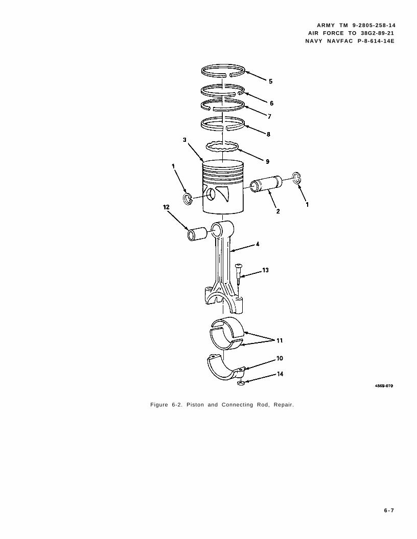
ARMY TM 9-2805-258-14AIR FORCE TO 38G2-89-21
NAVY NAVFAC P-8-614-14E
Figure 6-2. Piston and Connecting Rod, Repair.
6 - 7
ARMY TM 9-2805-258-14AIR FORCE TO 38G2-89-21NAVY NAVFAC P-8-614-14E
6-7. Piston and Connecting
c. Insta l la t ion. (figure 6-3)
Rod (cont).
(1) Install bearings (5) in oonnecting rod bearing cap (4) and connecting rod (6).
(2) Using ring compressor, install piston (1) with connecting rod (6) in cylinder (2).
N O T E
Before positioning oonnecting rod on crankshaft, ensure arrow on piston is in direction of
rotation. See crankcase area to left of cylinder for reference rotation arrow.
(3) Position connecting rod (6) on crankshaft (7).
(4) Install connecting rod bearing cap (4) and secure with two new nuts (3) and new bolts (8). Torque nuts
to 24-26 Ib-ft (51484 - 55774 gr cm).
6 - 8
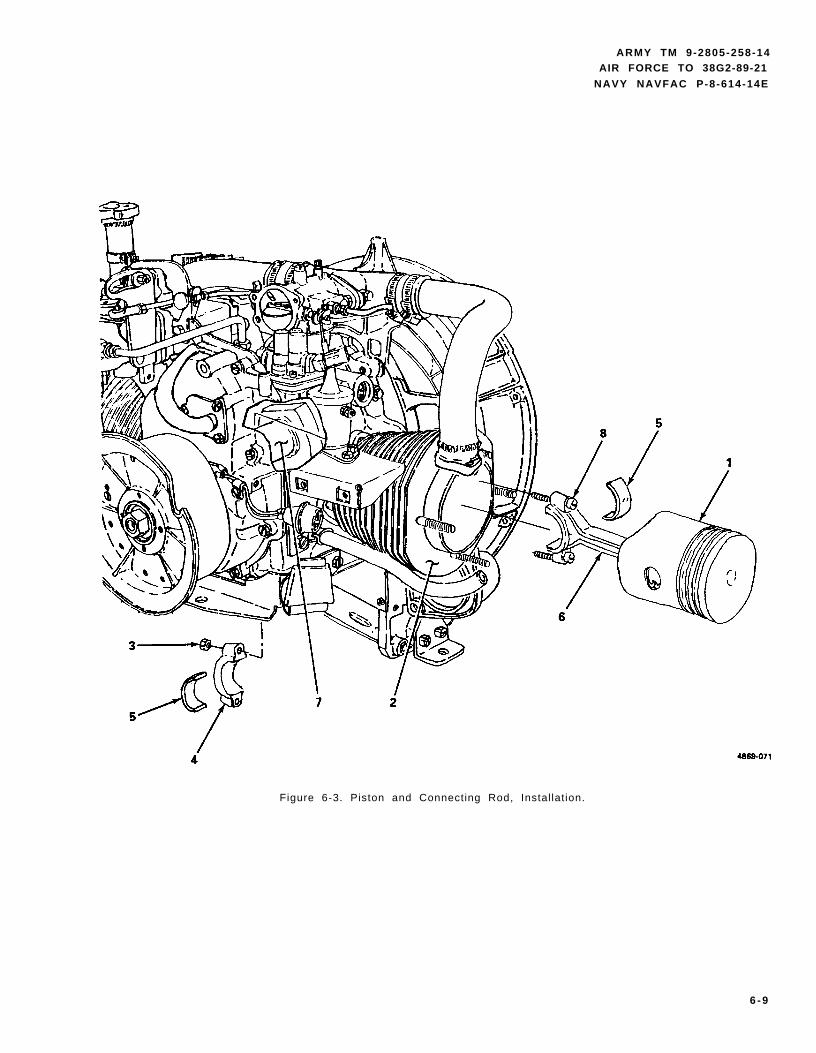
ARMY TM 9-2805-258-14AIR FORCE TO 38G2-89-21
NAVY NAVFAC P-8-614-14E
Figure 6-3. Piston and Connecting Rod, Installation.
6 - 9
ARMY TM 9-2805-258-14AIR FORCE TO 38G2-89-21NAVY NAVFAC P-8-614-14E
6-8. Cylinder
This task covers: a . R e m o v a l b . Inspect c. Installation
INITIAL SETUP
Tools Equipment Condi t ion
General Mechanic’s Tool Kit (Item 1, Appendix B) Piston and connecting rod removed (para. 6-7).
Mater ia ls /Par ts
Rags, Wiping (Item 7, Appendix D)
Solvent, Drycleaning (Item 8, Appendix D)
Gasket, Cylinder Mounting (NSN 5330-00-570-3224)
a. R e m o v a l . ( f igure 6-4)
Gently work cylinder (1) from side to side and remove cylinder (1) and gasket (2) from crankcase (3).
b. I n s p e c t . ( f igure 6-4)
W A R N I N G
Drycleaning solvent PD-680 used to clean parts is potentially dangerous to personnel and
property. Avoid repeated and prolonged skin contact. Do not use near open flame or
excessive heat. Flash point of solvent is 100°F.-138°F. (38°C.-60°C.).
(1) Clean cylinder (1) with drycleaning solvent and dry thoroughly.
N O T E
Any cylinder requiring honing or boring to restore concentricity and remove taper shall be
done by machine. Cylinders shall be honed or bored only to the degree necessary to
restore concentricity and/or remove taper. Refer to table 6-2 for wear limits.
(2) Inspect both cylinders (1) for wear or damage. Refer to table 6-2 for wear limits.
(3) Inspect studs (4) and replace if threads are stripped or otherwise damaged.
c. /nsta//ation. ( f igure 6-4)
(1) Ensure gasket mating surfaces are clean and old gasket material is removed.
(2) Install cylinder (1)
6 - 1 0
and gasket (2) and gently tap cylinder with block of wood or mallet to seat.
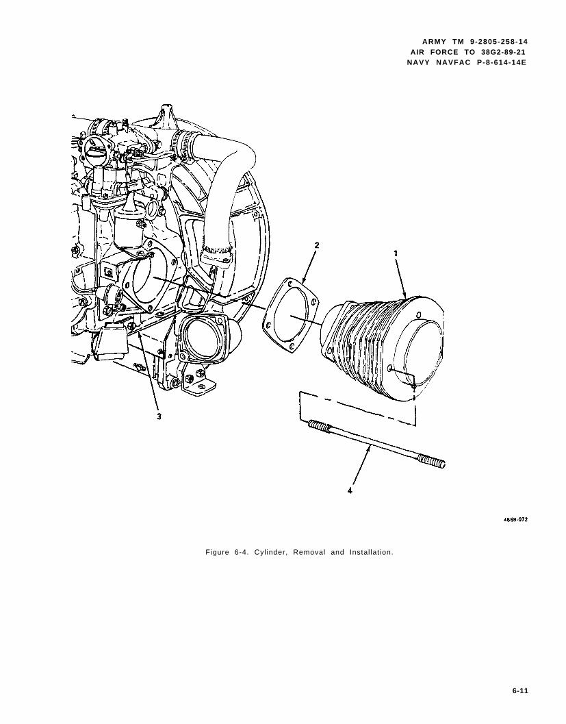
ARMY TM 9-2805-258-14AIR FORCE TO 38G2-89-21
NAVY NAVFAC P-8-614-14E
Figure 6-4. Cylinder, Removal and Installation.
6-11
ARMY TM 9-2805-258-14AIR FORCE TO 38G2-89-21NAVY NAVFAC P-8-614-14E
6-9. Camshaft, Camshaft Gear, and Bearing.
This task covers: a . R e m o v a l b. Installation
INITIAL SETUP
Tools Equipment Condi t ion
General Mechanic’s Tool Kit (Item 1, Appendix B) Oil pump gears removed (para. 5-9).
Fuel pump removed (para. 4-49).
Mater ia ls /Par ts Valve tappets removed (para. 5-20).
Magneto removed (para. 4-32)
Rags, Wiping (Item 7, Appendix D) Timing cover removed (para. 5-13).
Solvent, Drycleaning (Item 8, Appendix D)
a. R e m o v a l . ( f igure 6-5)
N O T E
Remove camshaft gear, key, camshaft, bearing and spacer as an assembly.
(1)
(2)
(3)
Remove two screws (1) and remove camshaft gear (2), key (3), camshaft (4), spacer (5) and bearing (6).
W A R N I N G
Drycleaning solvent PD-680 used to clean parts is potentially dangerous to personnel and
property. Avoid repeated and prolonged skin contact. Do not use near open flame or
excessive heat. Flash point of solvent is 100°F.-138°F. (38°C.-60°C.).
Clean all items with drycleaning solvent and dry thoroughly.
Inspect all items and replace worn or otherwise damaged parts. Refer to Table 6-2 for wear limits.
b. Installation. (figure 6-5)
(1) Install bearing (6), spacer (5), key (3) and camshaft gear (2) onto camshaft (4).
(2) Install camshaft (4) with all items installed, and aline timing mark on camshaft gear (2) with timing mark
on crankshaft gear (7).
(3) Instal l two screws (1).
6 - 1 2
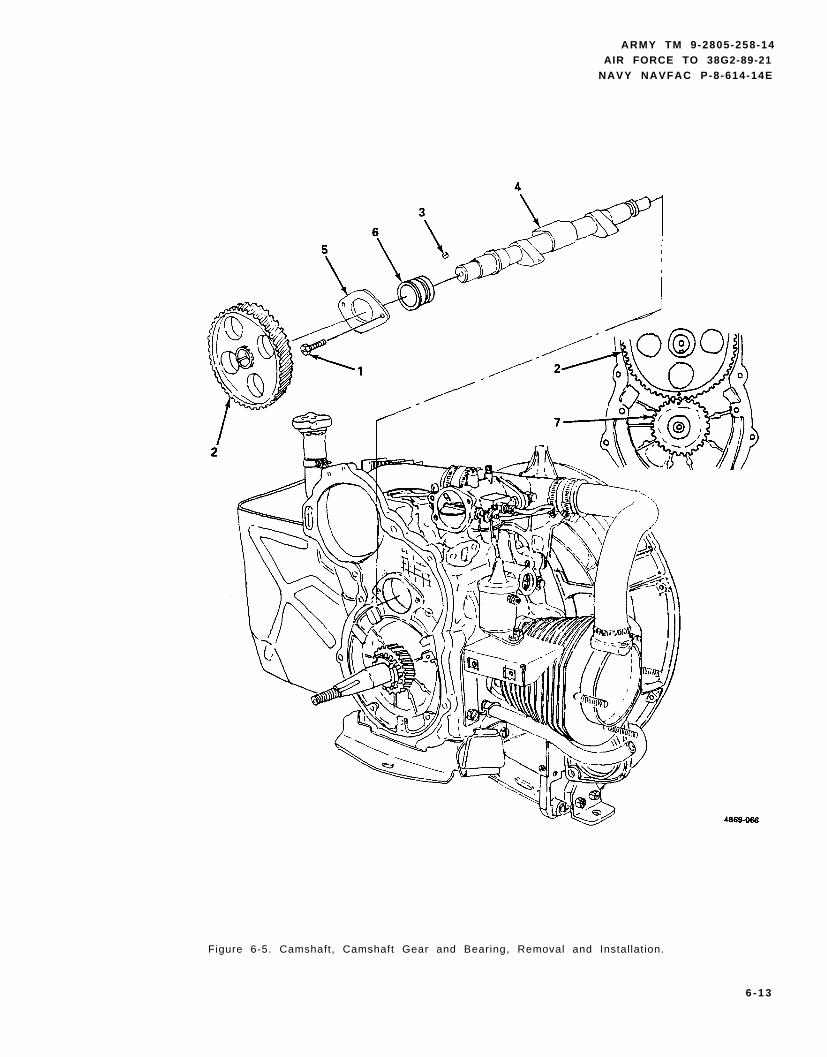
ARMY TM 9-2805-258-14AIR FORCE TO 38G2-89-21
NAVY NAVFAC P-8-614-14E
Figure 6-5. Camshaft, Camshaft Gear and Bearing, Removal and Installation.
6 - 1 3
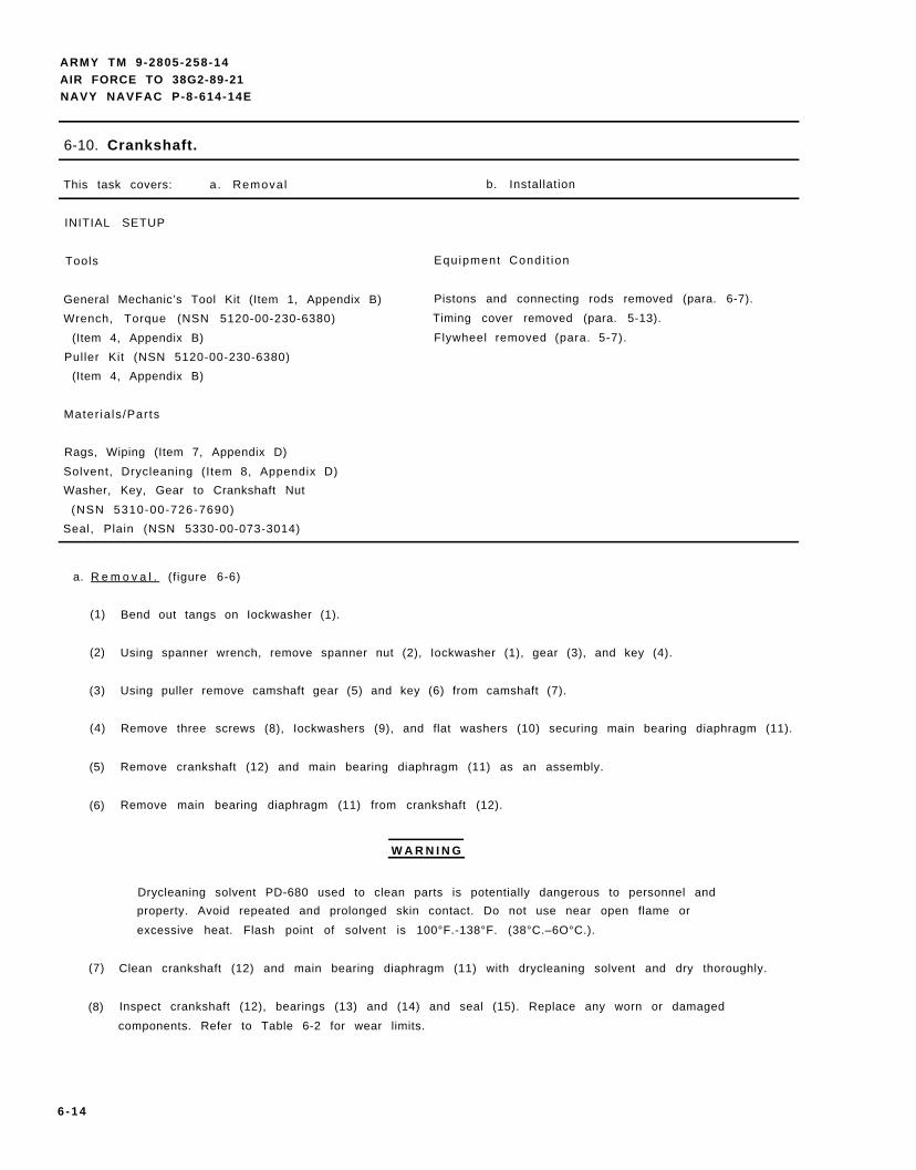
ARMY TM 9-2805-258-14AIR FORCE TO 38G2-89-21NAVY NAVFAC P-8-614-14E
6-10. Crankshaft.
This task covers: a . Removal b. Installation
INITIAL SETUP
Tools Equipment Condi t ion
General Mechanic’s Tool Kit (Item 1, Appendix B) Pistons and connecting rods removed (para. 6-7).
Wrench, Torque (NSN 5120-00-230-6380) Timing cover removed (para. 5-13).
(Item 4, Appendix B) Flywheel removed (para. 5-7).
Puller Kit (NSN 5120-00-230-6380)
(Item 4, Appendix B)
Mater ia ls /Par ts
Rags, Wiping (Item 7, Appendix D)
Solvent, Drycleaning (Item 8, Appendix D)
Washer, Key, Gear to Crankshaft Nut
(NSN 5310-00-726-7690)
Seal, Plain (NSN 5330-00-073-3014)
a. R e m o v a l . (figure 6-6)
(1)
(2)
(3)
(4)
(5)
(6)
(7)
(8)
6 - 1 4
Bend out tangs on Iockwasher (1).
Using spanner wrench, remove spanner nut (2), Iockwasher (1), gear (3), and key (4).
Using puller remove camshaft gear (5) and key (6) from camshaft (7).
Remove three screws (8), Iockwashers (9), and flat washers (10) securing main bearing diaphragm (11).
Remove crankshaft (12) and main bearing diaphragm (11) as an assembly.
Remove main bearing diaphragm (11) from crankshaft (12).
W A R N I N G
Drycleaning solvent PD-680 used to clean parts is potentially dangerous to personnel and
property. Avoid repeated and prolonged skin contact. Do not use near open flame or
excessive heat. Flash point of solvent is 100°F.-138°F. (38°C.–6O°C.).
Clean crankshaft (12) and main bearing diaphragm (11) with drycleaning solvent and dry thoroughly.
Inspect crankshaft (12), bearings (13) and (14) and seal (15). Replace any worn or damaged
components. Refer to Table 6-2 for wear limits.
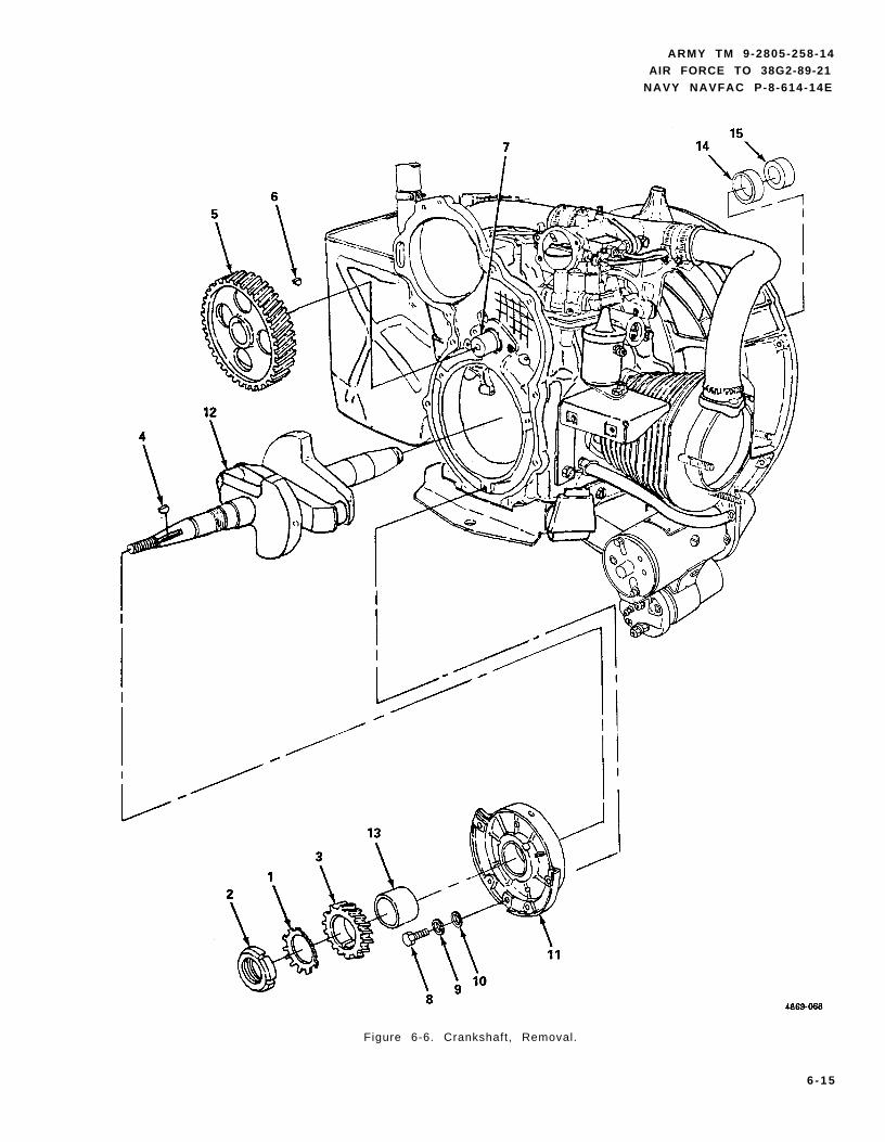
ARMY TM 9-2805-258-14AIR FORCE TO 38G2-89-21
NAVY NAVFAC P-8-614-14E
Figure 6-6. Crankshaft, Removal.
6 - 1 5
ARMY TM 9-2805-258-14AIR FORCE TO 38G2-89-21NAVY NAVFAC P-8-614-14E
6-10.
b.
Crankshaft (cont).
Insta l la t ion. (figure 6-7)
(1)
(2)
(3)
(4)
(5)
(6)
(7)
(8)
(9)
6 - 1 6
Install main bearing (13) in main bearing diaphragm (11).
Install bearing (14) if removed.
Install oil seal (15) if removed.
Install crankshaft (12) and main bearing diaphragm (11).
Install key (6) and camshaft gear (5).
Install key (4) and crankshaft gear (3). Aline timing marks on crankshaft gear (3) and camshaft
gear (5).
Install new Iockwasher (1) and spanner nut (2).
Bend out tangs on Iockwasher (1) to lock spanner nut (2).
Install main bearing diaphragm (11) with three screws (8), Iockwasher (9), and flat washers (10). Torque
screws to 41-57 in.-lb (7329 - 10189 gr cm).
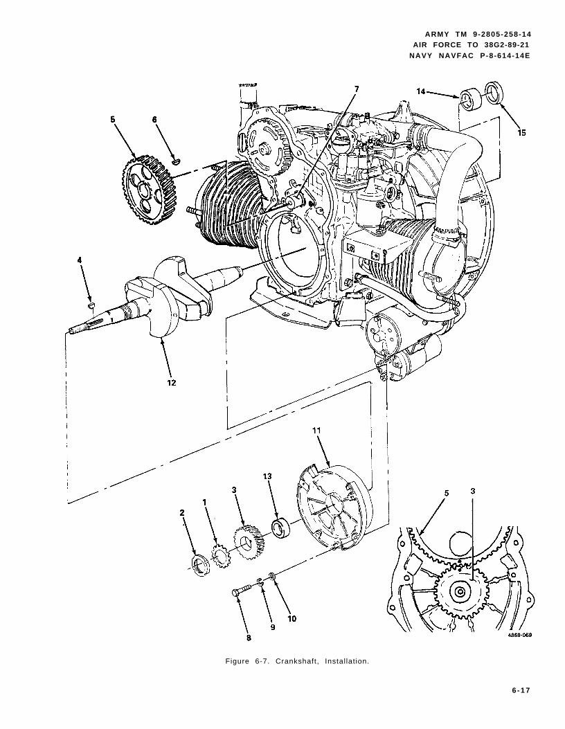
ARMY TM 9-2805-258-14AIR FORCE TO 38G2-89-21
NAVY NAVFAC P-8-614-14E
Figure 6-7. Crankshaft, Installation.
6 - 1 7
ARMY TM 9-2805-258-14AIR FORCE TO 38G2-89-21NAVY NAVFAC P-8-614-14E
6-11. Crankcase.
This task covers: Replacement
INITIAL SETUP
Tools Equipment Condi t ion
General Mechanics Tool Kit (Item 1, Appendix B) Cylinder removed (para. 6-8).
Governor removed (para. 4-44).
Mater ia ls /Par ts Flywheel housing removed (para. 5-8).
Pressure regulator valve removed (para. 4-26).
Rags, Wiping (Item 7, Appendix D) Camshaft removed (para. 6-9).
Solvent, Drycleaning (Item 8, Appendix D) Crankshaft removed (para. 6-10).
Intake manifold removed (para. 4-50).
Magneto removed (para. 4-32).
Crankcase breather removed (para. 4-27).
R e p l a c e m e n t . (figure 6-8)
W A R N I N G
Drycleaning solvent PD-680 used to clean parts is potentially dangerous to personnel and
property. Avoid repeated and prolonged skin contact. Do not use near open flame or
excessive heat. Flash point of solvent is 100°F.-138°F. (38°C.-60°C.).
(1) Clean crankcase (1) with drycleaning solvent and dry thoroughly.
(2) Inspect crankcase for cracks or signs of excessive wear.
N O T E
If replacing a crankcase, transfer items from old crankcase as needed.
(3) Replace crankcase if worn, cracked, or otherwise damaged.
6 - 1 8
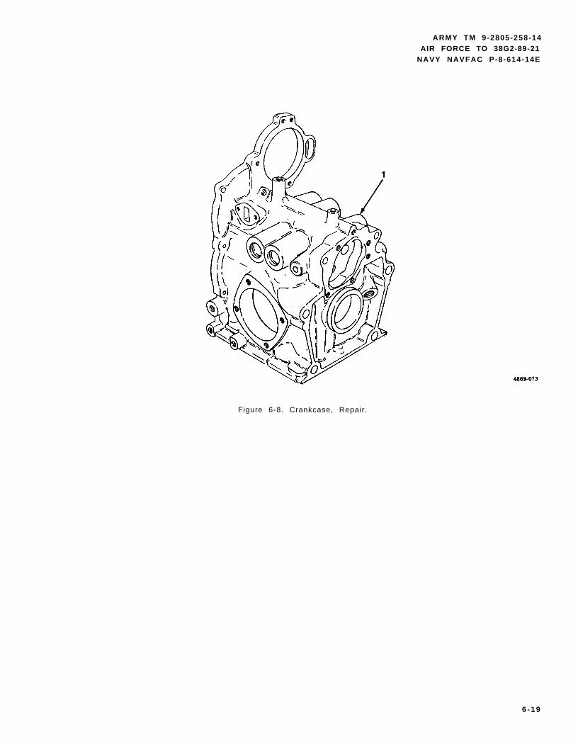
Figure 6-8. Crankcase, Repair.
ARMY TM 9-2805-258-14AIR FORCE TO 38G2-89-21
NAVY NAVFAC P-8-614-14E
6 - 1 9
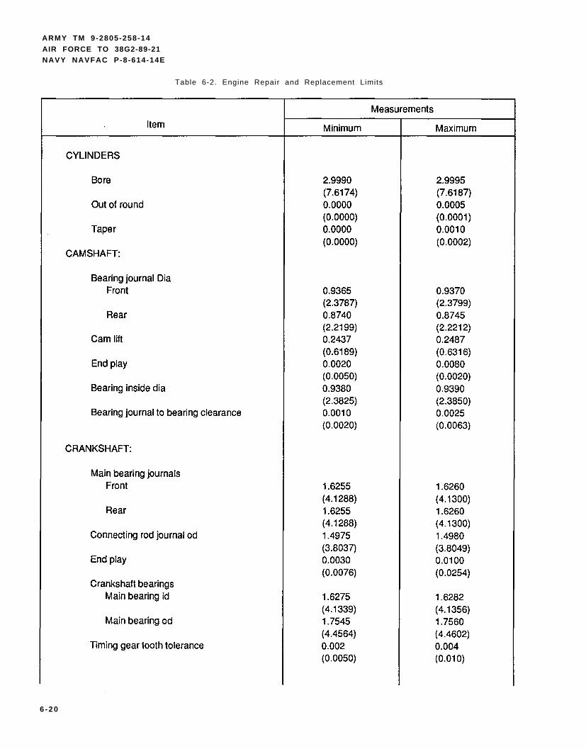
ARMY TM 9-2805-258-14AIR FORCE TO 38G2-89-21NAVY NAVFAC P-8-614-14E
Table 6-2. Engine Repair and Replacement Limits
6 - 2 0
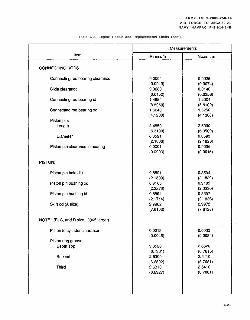
ARMY TM 9-2805-258-14AIR FORCE TO 38G2-89-21
NAVY NAVFAC P-8-614-14E
Table 6-2. Engine Repair and Replacements Limits (cont).
6-21
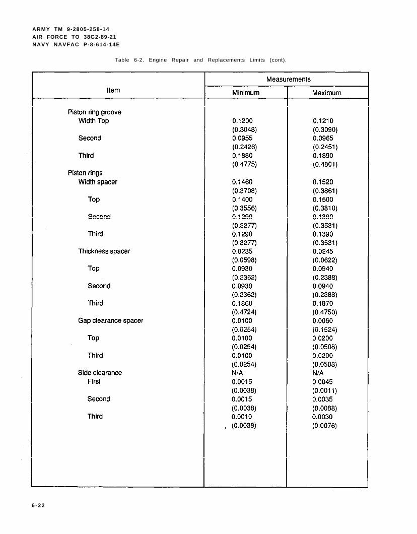
ARMY TM 9-2805-258-14AIR FORCE TO 38G2-89-21NAVY NAVFAC P-8-614-14E
Table 6-2. Engine Repair and Replacements Limits (cont).
6 - 2 2
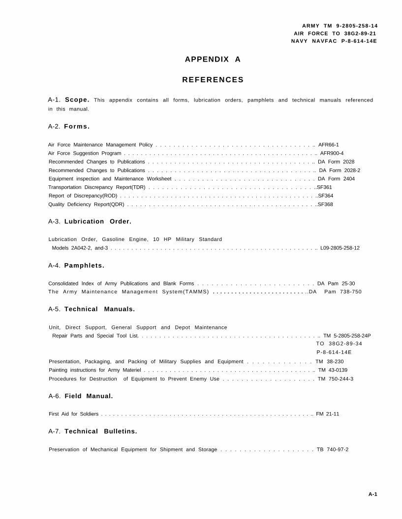
ARMY TM 9-2805-258-14AIR FORCE TO 38G2-89-21
NAVY NAVFAC P-8-614-14E
APPENDIX A
REFERENCES
A-1. Scope. This appendix contains all forms, lubrication orders, pamphlets and technical manuals referenced
in this manual.
A-2. Forms.
Air Force Maintenance Management Policy . . . . . . . . . . . . . . . . . . . . . . . . . . . . . . . . . . . .. AFR66-1
Air Force Suggestion Program . . . . . . . . . . . . . . . . . . . . . . . . . . . . . . . . . . . . . . . . . . . . . .. AFR900-4
Recommended Changes to Publications . . . . . . . . . . . . . . . . . . . . . . . . . . . . . . . . . . . . . .. DA Form 2028
Recommended Changes to Publications . . . . . . . . . . . . . . . . . . . . . . . . . . . . . . . . . . . . . .. DA Form 2028-2
Equipment inspection and Maintenance Worksheet . . . . . . . . . . . . . . . . . . . . . . . . . . . . . . . DA Form 2404
Transportation Discrepancy Report(TDR) . . . . . . . . . . . . . . . . . . . . . . . . . . . . . . . . . . . . ..SF361
Report of Discrepancy(ROD) . . . . . . . . . . . . . . . . . . . . . . . . . . . . . . . . . . . . . . . . . . . . . . ..SF364
Quality Deficiency Report(QDR) . . . . . . . . . . . . . . . . . . . . . . . . . . . . . . . . . . . . . . . . . . . ..SF368
A-3. Lubrication Order.
Lubrication Order, Gasoline Engine, 10 HP Military Standard
Models 2A042-2, and-3 . . . . . . . . . . . . . . . . . . . . . . . . . . . . . . . . . . . . . . . . . . . . . . . . . .. L09-2805-258-12
A-4. Pamphlets.
Consolidated lndex of Army Publications and Blank Forms . . . . . . . . . . . . . . . . . . . . . . . . . DA Pam 25-30
The Army Main tenance Management System(TAMMS) . . . . . . . . . . . . . . . . . . . . . . . . . ..DA Pam 738-750
A-5. Technical Manuals.
Unit, Direct Support, General Support and Depot Maintenance
Repair Parts and Special Tool List. . . . . . . . . . . . . . . . . . . . . . . . . . . . . . . . . . . . . . . . . .. TM 5-2805-258-24P
TO 38G2-89-34
P-8-614-14E
Presentation, Packaging, and Packing of Military Supplies and Equipment . . . . . . . . . . . . . TM 38-230
Painting instructions for Army Materiel . . . . . . . . . . . . . . . . . . . . . . . . . . . . . . . . . . . . . . . .. TM 43-0139
Procedures for Destruction of Equipment to Prevent Enemy Use . . . . . . . . . . . . . . . . . . . . TM 750-244-3
A-6. Field Manual.
First Aid for Soldiers . . . . . . . . . . . . . . . . . . . . . . . . . . . . . . . . . . . . . . . . . . . . . . . . . . . . .. FM 21-11
A-7. Technical Bulletins.
Preservation of Mechanical Equipment for Shipment and Storage . . . . . . . . . . . . . . . . . . . . TB 740-97-2
A-1
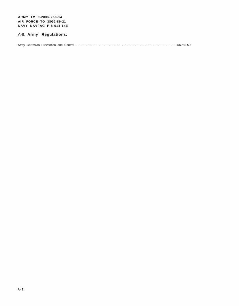
ARMY TM 9-2805-258-14AIR FORCE TO 38G2-89-21NAVY NAVFAC P-8-614-14E
A-8. Army Regulations.
Army Corrosion Prevention and Control . . . . . . . . . . . . . . . . . . . . . . . . . . . . . . . . . . . . . . .. AR750-59
A - 2
ARMY TM 9-2805-258-14AIR FORCE TO 38G2-89-21
NAVY NAVFAC P-8-614-14E
APPENDIX B
MAINTENANCE ALLOCATION CHART
Section l . INTRODUCTION
B-1. Maintenance Allocation Chart (MAC). This MAC assigns maintenance functions in accordance
with the Four Level Maintenance Concept.
B-2. Use of the Maintenance Allocation Chart, Section Il.
a. The MAC assigns maintenance functions based on the fol lowing considerations:
(1)
(2)
(3)
Skil ls available.
Work time required.
Tools and test equipment required and/or available.
b. If a lower level of maintenance identified in column (4) of the MAC cannot perform all tasks of a single
maintenance function (e.g., test, repair), then the higher level that can perform other tasks of that function is also
indicated.
c. Higher maintenance levels are automatically authorized to perform maintenance functions assigned to a
lower maintenance level.
d. Higher maintenance levels wil l perform the maintenance functions of lower maintenance levels when
required or directed by the Commander who has authority to direct such tasking.
e. Assignment of a maintenance function in the MAC does not carry automatic authorization to carry the
related spare or repair parts in stock. Information to requisition or secure parts will be as specified in t he
associated RPSTL.
f. Normally, there wil l be no deviation from the assigned level of maintenance. However, in cases of
operational necessity, maintenance functions assigned a higher level may, at the request of the lower level, be
assigned to the lower level on a one-time basis, if specifically authorized by the maintenance officer of the higher
level to which the function is assigned. In such a case, the special tools, equipment, etc., required by the lower
level to perform this function will be furnished by the higher level assigned the function. Also, transfer of a function
to a lower level does not relieve the higher level of responsibility for the function, so the higher level will provide
technical supervision and inspection of the function being performed at the lower level.
B-3. Maintenance Functions. Maintenance functions will be limited to and defined as follows:
a. Inspec t . TO determine the serviceabil i ty of an item by comparing its physical, mechanical, and/or electrical
characteristics with established standards through examination (e.g., by sight, sound, or feel).
b. Tes t . . To verify serviceability and detect incipient failure by measuring the mechanical or electrical
characteristics of an item and comparing those characteristics with prescribed standards.
B-1
ARMY TM 9-2805-258-14AIR FORCE TO 38G2-89-21NAVY NAVFAC P-8-614-14E
c. Service. Operations required periodically to keep an item in proper operating condition, i.e., to clean
(includes decontaminate), to preserve, to drain, or to replenish fuel, lubricants, hydraulic fluids, or compressed air
supplies.
d. Adjust. To maintain within prescribed limits, by bringing into proper or exact position, or by setting the
operating characteristics to the specified parameters.
e. Al ine. To adjust specified variable elements of an item to bring about optimum or desired performance.
f. Calibrate. To determine and cause corrections to be made or to be adjusted on instruments or test
measuring and diagnostic equipment used in precision measurement. Consists of comparison of two instruments,
one of which is a certified standard of known accuracy, to detect and adjust any discrepancy in the accuracy of the
instrument being compared.
g. Ins ta l l . The act of emplacing, seating, or fixing into position an item, part, or module (component assembly)
in a manner to allow the proper functioning of an equipment or system.
h. Rep/ace. The act of substituting a serviceable like type part, a subassembly, or module (component or
assembly) for an unserviceable counterpart.
i. R e p a i r . The application of maintenance services (inspect, test, service, adjust, al ine, calibrate, or replace)
or other maintenance actions (welding, grinding, riveting, straightening, facing, remachining, or resurfacing) to
restore serviceability to an item by correcting specific damage, fault, malfunction, or failure in a part, subassembly,
module (component or assembly), end item, or system.
j. O v e r h a u l . That maintenance effort (service/action) necessary to restore an item to a completely
serviceable operational condition as prescribed by maintenance standards in appropriate technical publications
(i.e., DMWR). Overhaul does not normally return an item to a like new condition.
k. Rebuild. Consists of those services/actions necessary for the restoration of unserviceable equipment to a
like new condition in accordance with original manufacturing standards. Rebuild is the highest degree of materiel
maintenance applied to Army equipment. The rebuild operation includes the act of returning to zero those age
measurements (hours/miles, etc.) considered in classifying Army equipment/components.
B-4. Explanation of Columns in the MAC, Section Il.
a. Column [1), Group Number. Column 1 lists functional group code numbers which are assigned to identify
maintenance signif icant components, assemblies, subassemblies, and modules to their next higher assembly.
b. Column (2). Component / A s s e mbly. Column 2 contains the item names of components, assemblies,
subassemblies, and modules for which group numbers (column 1 ) are assigned and for which maintenance is
author ized.
c. Column (2) Maintenance F u n c t i o n . Column 3 lists the functions to be performed on items listed in Column
2. (Function definitions are contained in paragraph A-3.)
B-2
ARMY TM 9-2805-258-14AIR FORCE TO 38G2-89-21
NAVY NAVFAC P-8-614-14E
d. Co/umn (4). Maintenance Leve/. The maintenance levels, Unit, Direct Support, General Support, and
Depot, are allotted separate subcolumns within column 4. Entry of a work time figure (such as 1.0, 0.2) in a
subcolumn indicates that that level is authorized to perform the function listed in column 3, and the average time
required to do the function is the work time figure. If the number or complexity of tasks within a maintenance
function varies from one maintenance level to another, the applicable work time figure for each level will be
entered for that function. The work time figure represents the average time it takes to restore a
component/assembly to a serviceable condition under a typical field operating environment.
e. Column (5). Tools and Equipment. Column 5 specifies, by code, common tool sets (not individual tools
from those sets), common TM DE, and special tools, TM DE, and support equipment required to perform a
designated function. The code in Column 5 keys to the listing in Section Ill of the MAC.
f. Co lumn (6) . Remarks . This column when applicable, contains a letter code with is keyed to an explanation
of the code contained in Section IV of the MAC.
B-5. Explanation of Columns in the MAC, Section Ill.
a. iColumn (1). Tool or Test Equipment Reference Code . The tool or test equipment reference code correlates
with a code used in the MAC, Section ll, Column 5.
b . Column (2) Maintenance Category. The lowest category of maintenance authorized to use the tool or test
equipment.
c. Column (3). Nornenc/ature. Name or identification of the tool or test equipment.
d. Column (4). National/NATO Stock Number. The National stock number of the tool or test equipment.
e. Column (5). Too/ N u m b e r . The manufacturer ’s par t number.
B-6. Explanation of Columns in the MAC, Section IV.
a. Column (1) Reference Code. The code recorded in column 6, Section Il.
b. Co/umn (2), Remarks. This column lists information pertinent to the maintenance function being performed
as indicated in the MAC, Section Il.
B-3
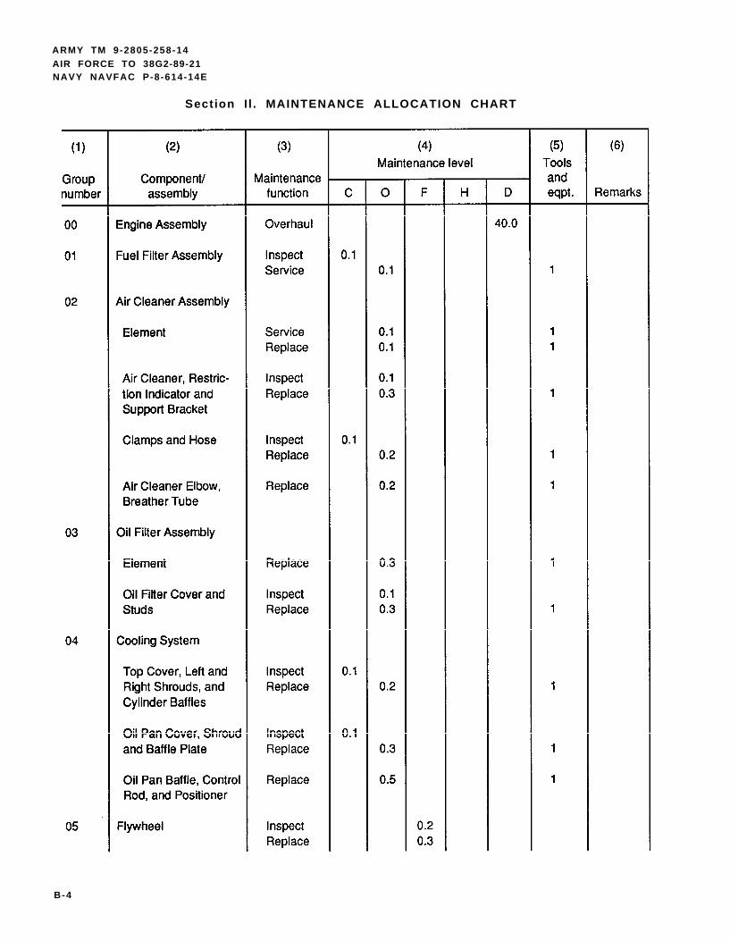
ARMY TM 9-2805-258-14AIR FORCE TO 38G2-89-21NAVY NAVFAC P-8-614-14E
Section I l . MAINTENANCE ALLOCATION CHART
B-4
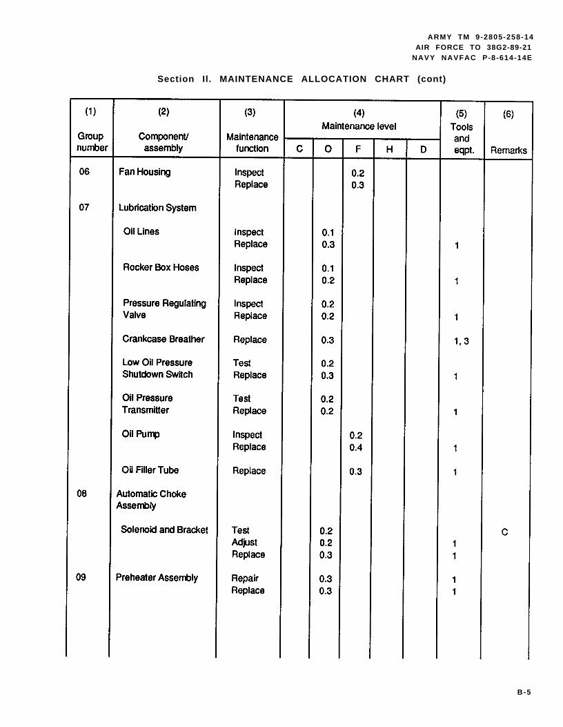
ARMY TM 9-2805-258-14AIR FORCE TO 38G2-89-21
NAVY NAVFAC P-8-614-14E
Section Il. MAINTENANCE ALLOCATION CHART (cont)
B-5
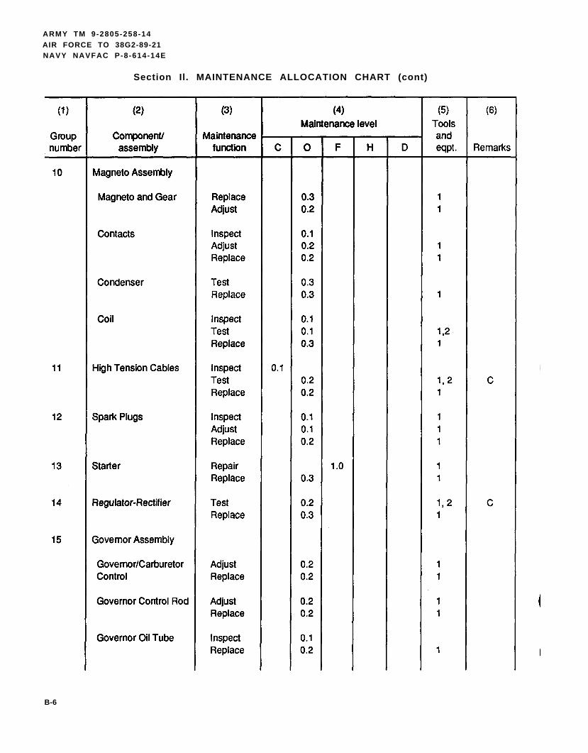
ARMY TM 9-2805-258-14AIR FORCE TO 38G2-89-21NAVY NAVFAC P-8-614-14E
Section Il. MAINTENANCE ALLOCATION CHART (cont)
B-6
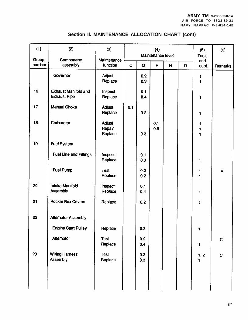
ARMY TM 9-2805-258-14AIR FORCE TO 38G2-89-21
NAVY NAVFAC P-8-614-14E
Section Il. MAINTENANCE ALLOCATION CHART (cont)
B-7
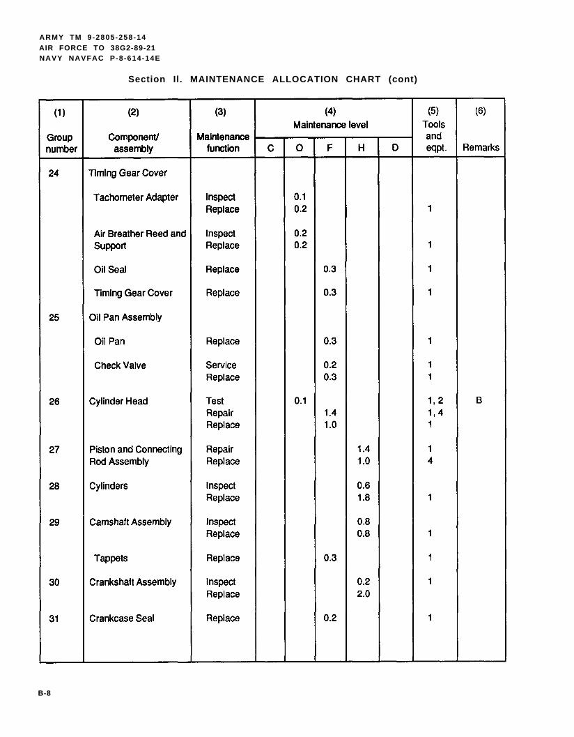
ARMY TM 9-2805-258-14AIR FORCE TO 38G2-89-21NAVY NAVFAC P-8-614-14E
Section Il. MAINTENANCE ALLOCATION CHART (cont)
B-8
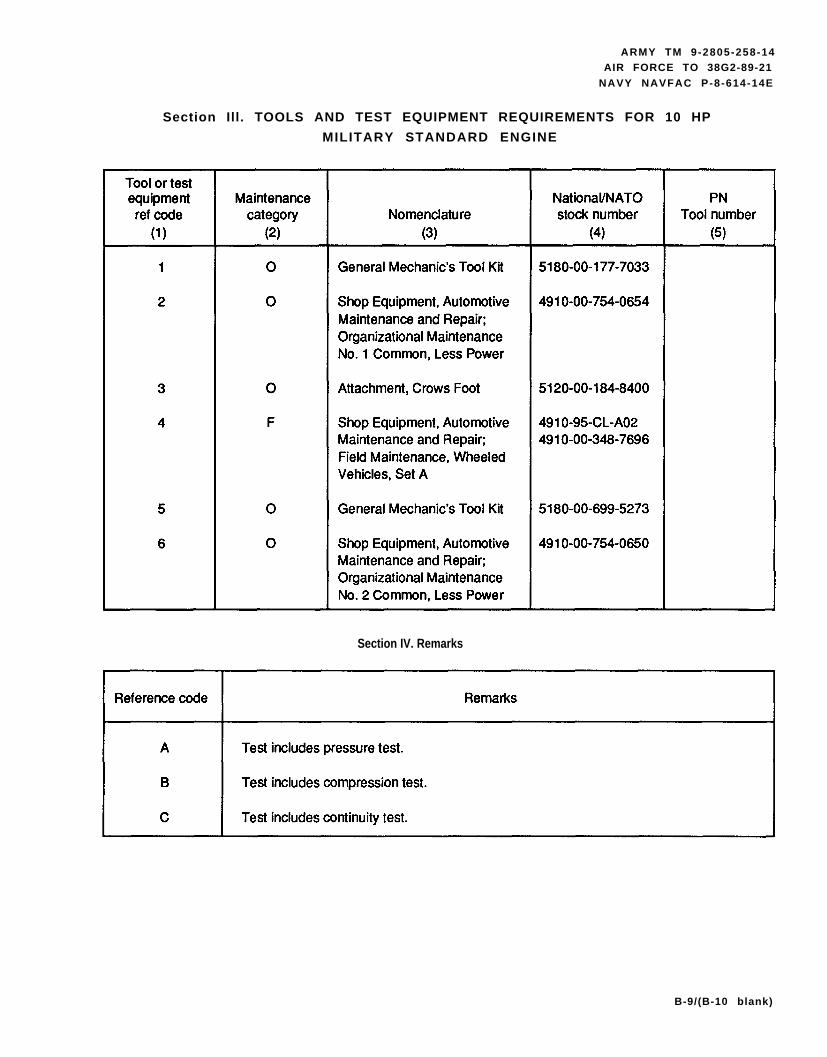
ARMY TM 9-2805-258-14AIR FORCE TO 38G2-89-21
NAVY NAVFAC P-8-614-14E
Section Ill. TOOLS AND TEST EQUIPMENT REQUIREMENTS FOR 10 HP
MILITARY STANDARD ENGINE
Section IV. Remarks
B-9/(B-10 blank)

COMPONENTS OF END
C1. S c o p e .
ARMY TM 9-2805-258-14AIR FORCE TO 38G2-89-21
NAVY NAVFAC P-8-614-14E
APPENDIX C
ITEM AND BASIC ISSUE ITEMS LISTS
Section l INTRODUCTION
This appendix lists components of end item and basic issue items for the 10 HP Military Standard Engine to help
you inventory items required for safe and efficient operation.
C-2. General.
The Components of End Item and Basic Issue Items Lists are divided into the following sections.
a. Section Il. Components of End item. This listing is for informational purposes only, and is not authority to
requisition replacements. The items are part of the end item, but are removed and separately packaged for
transportation or shipment. As part of the end item, these items must be with the end item whenever it is issued
or transferred between properly accounts. Illustrations are furnished to assist you in identifying the items.
b. S e c tion Il l . Basic Issue Items. These are the minimum essential items required to place the 10 HP Military
standard engine in operation. The illustrations will assist you with hard-to-identify items. This manual is your
authority to requesf/frequisition replacement Bll, based on TOE/MTOE authorization of the end item.
C-3. Explanation of Columns.
The following provides an explanation of columns found in the tabular listings:
a. Co/umn (1). // /ustration Number (///us Number). This column indicates the number of the illustration in
which the item is shown.
b. Column (2) . Nat ional Stock Number. Indicates the National Stock Number assigned to the item and will be
used for requisit ioning purposes.
c. Column (3). Description. Indicates the Federal item name, and, if required, a minimum description to
identify and locate the item. The last line for each item indicates the FSCM (in parentheses) followed by the part
number.
d. Co lumn (4) . Unit of Measure (U/M). Indicates the measure used in performing the actual
operational/maintenance function. This measure is expressed by a two-character alphabetical abbreviation (e.g.,
ea, in., pr).
e. Column [5). Quantitv Requ ired (QTY RQR). indicates the quantity of the item authorized to be used with/on
the equipment.
C-1
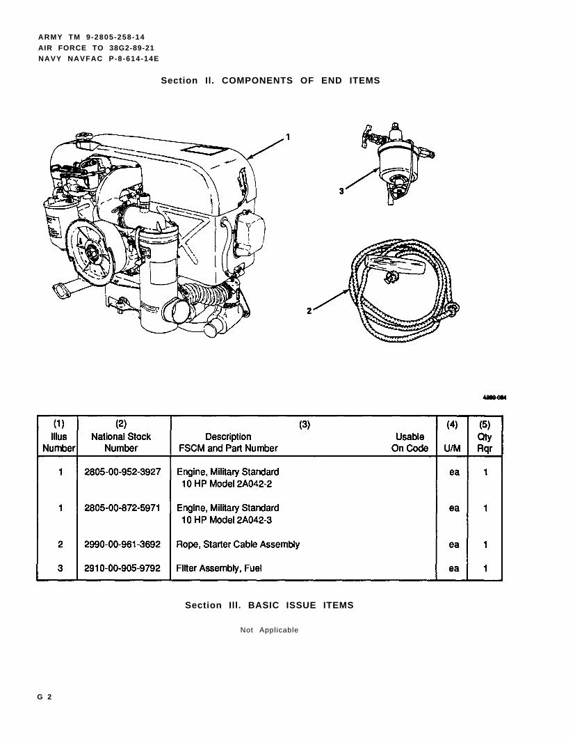
ARMY TM 9-2805-258-14AIR FORCE TO 38G2-89-21NAVY NAVFAC P-8-614-14E
Section Il. COMPONENTS OF END ITEMS
Section Ill. BASIC ISSUE ITEMS
Not Applicable
G 2
ARMY TM 9-2805-258-14AIR FORCE TO 38G2-89-21
NAVY NAVFAC P-8-614-14E
APPENDIX D
EXPENDABLE/DURABLE SUPPLIES
Section l . INTRODUCTION
MATERIALS LIST
D-1. Scope. This listing is for informational purposes only and is not authority to requisition the listed items.
These items are authorized to you by CTA 50-970, Expendable/Durable Items (except medical, class V, repair
parts, and heraldic items).
D-2. Explanation of Columns.
a. Column (1) - Item Number. This number is assigned to the entry in the listing and is referenced in the
narrative instructions to identify the material (e.g., “Use cleaning compound, item 5, appendix C)”.
b . C o l u m n ( 2 ) - L ev e / . This column identifies the lowest level of maintenance that requires the listed item.
C - O p e r a t o r / C r e w
O - U n i t M a i n t e n a n c e
F - D i rec t Suppor t Main tenance
H - Genera l Suppor t Main tenance
c. Column (3) – National Stock Number.
request or requisition the item.
This is the National stock number assigned to the item; use it to
d. Column (4) - D e s c r i p t i o n .. .
Indicates the Federal item name, and, if required, a description to identify the
item. The last line for each item indicates the Commercial and Government Entity (CAGE) in parentheses
followed by the part number.
d. Column (5) - Unit of Measure (lJ/M). Indicates the measure used in performing the actual maintenance
function. This measure is expressed by a two-character alphabetical abbreviation (e.g., ea, in., pr). If the unit of
measure differs from the unit of issue, requisition the lowest unit of issue that will satisfy your requirements.
D-1
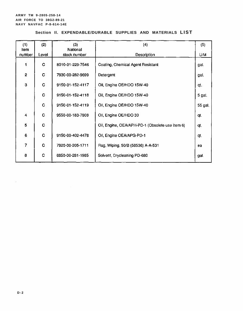
ARMY TM 9-2805-258-14
AIR FORCE TO 38G2-89-21NAVY NAVFAC P-8-614-14E
Section Il. EXPENDABLE/DURABLE SUPPLIES AND MATERIALS L I S T
D - 2
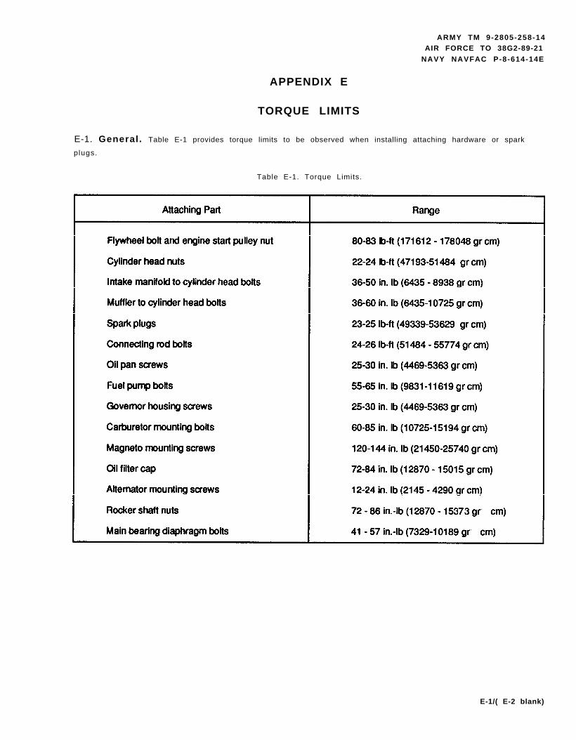
ARMY TM 9-2805-258-14AIR FORCE TO 38G2-89-21
NAVY NAVFAC P-8-614-14E
APPENDIX E
TORQUE LIMITS
E-1. General. Table E-1 provides torque limits to be observed when installing attaching hardware or spark
plugs.
Table E-1. Torque Limits.
E-1/( E-2 blank)
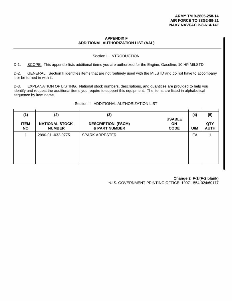
ARMY TM 9-2805-258-14AIR FORCE TO 38G2-89-21
NAVY NAVFAC P-8-614-14E
APPENDIX FADDITIONAL AUTHORIZATION LIST (AAL)
Section I. INTRODUCTION
D-1. SCOPE. This appendix lists additional items you are authorized for the Engine, Gasoline, 10 HP MILSTD.
D-2. GENERAL. Section II identifies items that are not routinely used with the MILSTD and do not have to accompanyit or be turned in with it.
D-3. EXPLANATION OF LISTING. National stock numbers, descriptions, and quantities are provided to help youidentify and request the additional items you require to support this equipment. The items are listed in alphabeticalsequence by item name.
Section II. ADDITIONAL AUTHORIZATION LIST
(1) (2) (3) (4) (5)USABLE
ITEM NATIONAL STOCK- DESCRIPTION, (FSCM) ON QTYNO NUMBER & PART NUMBER CODE U/M AUTH
1 2990-01 -032-0775 SPARK ARRESTER EA 1
Change 2 F-1/(F-2 blank)*U.S. GOVERNMENT PRINTING OFFICE: 1997 - 554-024/60177
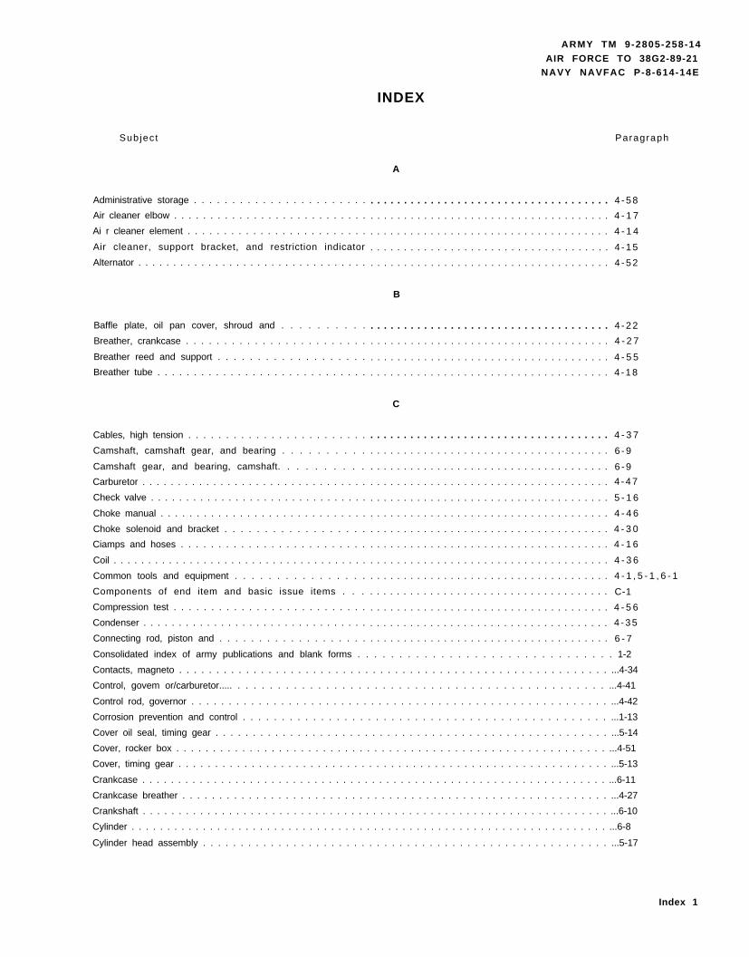
ARMY TM 9-2805-258-14AIR FORCE TO 38G2-89-21
NAVY NAVFAC P-8-614-14E
INDEX
Subjec t
Administrative storage . . . . . . . . . . . . . . . . . . . . . . .
Air cleaner elbow . . . . . . . . . . . . . . . . . . . . . . . . . . .
Ai r cleaner element . . . . . . . . . . . . . . . . . . . . . . . . .
Air cleaner, support bracket, and restriction indicator
Alternator . . . . . . . . . . . . . . . . . . . . . . . . . . . . . . . . .
Baffle plate, oil pan cover, shroud and . . . . . . . . . .
Breather, crankcase . . . . . . . . . . . . . . . . . . . . . . . .
Breather reed and support . . . . . . . . . . . . . . . . . . .
Breather tube . . . . . . . . . . . . . . . . . . . . . . . . . . . . .
Cables, high tension . . . . . . . . . . . . . . . . . . . . . . . .
Camshaft, camshaft gear, and bearing . . . . . . . . . .
Camshaft gear, and bearing, camshaft. . . . . . . . . .
Carburetor . . . . . . . . . . . . . . . . . . . . . . . . . . . . . . . .
Check valve . . . . . . . . . . . . . . . . . . . . . . . . . . . . . . .
Choke manual . . . . . . . . . . . . . . . . . . . . . . . . . . . . .
Choke solenoid and bracket . . . . . . . . . . . . . . . . . .
Ciamps and hoses . . . . . . . . . . . . . . . . . . . . . . . . .
Coil . . . . . . . . . . . . . . . . . . . . . . . . . . . . . . . . . . . . .
Common tools and equipment . . . . . . . . . . . . . . . .
Components of end item and basic issue items . . .
Compression test . . . . . . . . . . . . . . . . . . . . . . . . . .
Condenser . . . . . . . . . . . . . . . . . . . . . . . . . . . . . . . .
Connecting rod, piston and . . . . . . . . . . . . . . . . . . .
Paragraph
A
. . . . . . . . . . . . . . . . . . . . . . . . . . . . . . . . . . . . 4 - 5 8
. . . . . . . . . . . . . . . . . . . . . . . . . . . . . . . . . . . . 4 - 1 7
. . . . . . . . . . . . . . . . . . . . . . . . . . . . . . . . . . . . 4 - 1 4
. . . . . . . . . . . . . . . . . . . . . . . . . . . . . . . . . . . . 4 - 1 5
. . . . . . . . . . . . . . . . . . . . . . . . . . . . . . . . . . . . 4 - 5 2
B
. . . . . . . . . . . . . . . . . . . . . . . . . . . . . . . . . . . . 4 - 2 2
. . . . . . . . . . . . . . . . . . . . . . . . . . . . . . . . . . . . 4 - 2 7
. . . . . . . . . . . . . . . . . . . . . . . . . . . . . . . . . . . . 4 - 5 5
. . . . . . . . . . . . . . . . . . . . . . . . . . . . . . . . . . . . 4 - 1 8
C
. . . . . . . . . . . . . . . . . . . . . . . . . . . . . . . . . . . . 4 - 3 7
. . . . . . . . . . . . . . . . . . . . . . . . . . . . . . . . . . . . 6 - 9
. . . . . . . . . . . . . . . . . . . . . . . . . . . . . . . . . . . . 6 - 9
. . . . . . . . . . . . . . . . . . . . . . . . . . . . . . . . . . . . 4 - 4 7
. . . . . . . . . . . . . . . . . . . . . . . . . . . . . . . . . . . . 5 - 1 6
. . . . . . . . . . . . . . . . . . . . . . . . . . . . . . . . . . . . 4 - 4 6
. . . . . . . . . . . . . . . . . . . . . . . . . . . . . . . . . . . . 4 - 3 0
. . . . . . . . . . . . . . . . . . . . . . . . . . . . . . . . . . . . 4 - 1 6
. . . . . . . . . . . . . . . . . . . . . . . . . . . . . . . . . . . . 4 - 3 6
. . . . . . . . . . . . . . . . . . . . . . . . . . . . . . . . . . . . 4 - 1 , 5 - 1 , 6 - 1
. . . . . . . . . . . . . . . . . . . . . . . . . . . . . . . . . . . . C-1
. . . . . . . . . . . . . . . . . . . . . . . . . . . . . . . . . . . . 4 - 5 6
. . . . . . . . . . . . . . . . . . . . . . . . . . . . . . . . . . . . 4 - 3 5
. . . . . . . . . . . . . . . . . . . . . . . . . . . . . . . . . . . . 6 - 7
Consolidated index of army publications and blank forms . . . . . . . . . . . . . . . . . . . . . . . . . . . . . . . 1-2
Contacts, magneto . . . . . . . . . . . . . . . . . . . . . . . . . . . . . . . . . . . . . . . . . . . . . . . . . . . . . . . . . . ...4-34
Control, govem or/carburetor..... . . . . . . . . . . . . . . . . . . . . . . . . . . . . . . . . . . . . . . . . . . . . . . ...4-41
Control rod, governor . . . . . . . . . . . . . . . . . . . . . . . . . . . . . . . . . . . . . . . . . . . . . . . . . . . . . . . . ...4-42
Corrosion prevention and control . . . . . . . . . . . . . . . . . . . . . . . . . . . . . . . . . . . . . . . . . . . . . . . ...1-13
Cover oil seal, timing gear . . . . . . . . . . . . . . . . . . . . . . . . . . . . . . . . . . . . . . . . . . . . . . . . . . . . . ...5-14
Cover, rocker box . . . . . . . . . . . . . . . . . . . . . . . . . . . . . . . . . . . . . . . . . . . . . . . . . . . . . . . . . . . ...4-51
Cover, timing gear . . . . . . . . . . . . . . . . . . . . . . . . . . . . . . . . . . . . . . . . . . . . . . . . . . . . . . . . . . . ...5-13
Crankcase . . . . . . . . . . . . . . . . . . . . . . . . . . . . . . . . . . . . . . . . . . . . . . . . . . . . . . . . . . . . . . . . . ...6-11
Crankcase breather . . . . . . . . . . . . . . . . . . . . . . . . . . . . . . . . . . . . . . . . . . . . . . . . . . . . . . . . . . ...4-27
Crankshaft . . . . . . . . . . . . . . . . . . . . . . . . . . . . . . . . . . . . . . . . . . . . . . . . . . . . . . . . . . . . . . . . . ...6-10
Cylinder . . . . . . . . . . . . . . . . . . . . . . . . . . . . . . . . . . . . . . . . . . . . . . . . . . . . . . . . . . . . . . . . . . . ...6-8
Cylinder head assembly . . . . . . . . . . . . . . . . . . . . . . . . . . . . . . . . . . . . . . . . . . . . . . . . . . . . . . ...5-17
Index 1
ARMY TM 9-2805-258-14AIR FORCE TO 38G2-89-21NAVY NAVFAC P-8-614-14E
S u b j e c t
INDEX (cont)
Paragraph
D
equipment . . . . . . . . . . . . . . . . . . . . . . . . . . . . . . . . . . . . . . . . . . . . . .. . . . . . . . . .1-10D a t a ,
Destruction of Arrny materiel to prevent enemy use . . . . . . . . . . . . . . . . . . . . . . . . . . . . . . . . . ...1-5
Dtiferences between models . . . . . . . . . . . . . . . . . . . . . . . . . . . . . . . . . . . . . . . . . . . . . . . . . . . ...1-11
Diiferent attiiudes, operation in... . . . . . . . . . . . . . . . . . . . . . . . . . . . . . . . . . . . . . . . . . . . . . . ...2-14
Direct support maintenance
Carburetor . . . . . . . . . . . . . . . . . . . . . . . . . . . . . . . . . . . . . . . . . . . . . . . . . . . . . . . . . . . . . ...5-12
Check valve . . . . . . . . . . . . . . . . . . . . . . . . . . . . . . . . . . . . . . . . . . . . . . . . . . . . . . . . . . . . ...5-16
Cylinder head assembly . . . . . . . . . . . . . . . . . . . . . . . . . . . . . . . . . . . . . . . . . . . . . . . . . . ...5-17
Flywheel . . . . . . . . . . . . . . . . . . . . . . . . . . . . . . . . . . . . . . . . . . . . . . . . . . . . . . . . . . . . . . ...5-7
Fan housing . . . . . . . . . . . . . . . . . . . . . . . . . . . . . . . . . . . . . . . . . . . . . . . . . . . . . . . . . . . . ...5-8
Intake and exhaust valves . . . . . . . . . . . . . . . . . . . . . . . . . . . . . . . . . . . . . . . . . . . . . . . . . ...5-19
Oil filler tube and gage . . . . . . . . . . . . . . . . . . . . . . . . . . . . . . . . . . . . . . . . . . . . . . . . . . . ...5-10
Oil pan . . . . . . . . . . . . . . . . . . . . . . . . . . . . . . . . . . . . . . . . . . . . . . . . . . . . . . . . . . . . . . . . ...5-15
Oil pump gears, spacer, and oil pump cover . . . . . . . . . . . . . . . . . . . . . . . . . . . . . . . . . . . ...5-9
Rear oil seal . . . . . . . . . . . . . . . . . . . . . . . . . . . . . . . . . . . . . . . . . . . . . . . . . . . . . . . . . . . ...5-19
Rockers . . . . . . . . . . . . . . . . . . . . . . . . . . . . . . . . . . . . . . . . . . . . . . . . . . . . . . . . . . . . . . . ...5-18
Starter assembly . . . . . . . . . . . . . . . . . . . . . . . . . . . . . . . . . . . . . . . . . . . . . . . . . . . . . . . . ...5-11
Timing gear cover . . . . . . . . . . . . . . . . . . . . . . . . . . . . . . . . . . . . . . . . . . . . . . . . . . . . . . . ...5-13
Timing gear cover oil seal . . . . . . . . . . . . . . . . . . . . . . . . . . . . . . . . . . . . . . . . . . . . . . . . . ...5-14
Valve tappets . . . . . . . . . . . . . . . . . . . . . . . . . . . . . . . . . . . . . . . . . . . . . . . . . . . . . . . . . . . . ..5-20
Direct support troubleshooting . . . . . . . . . . . . . . . . . . . . . . . . . . . . . . . . . . . . . . . . . . . . . . . . . . . . 5 - 5
Dusty or sandy areas, operation in . . . . . . . . . . . . . . . . . . . . . . . . . . . . . . . . . . . . . . . . . . . . . . . . . 2-11
E
Element, air cleaner . . . . . . . . . . . . . . . . . . . . . . . . . . . . . . . . . . . . . . . . . . . . . . . . . . . . . . . . . ...4-14
Element, oil fitter . . . . . . . . . . . . . . . . . . . . . . . . . . . . . . . . . . . . . . . . . . . . . . . . . . . . . . . . . . . . ...4-19
Enemy use, destruction of army materiel to prevent . . . . . . . . . . . . . . . . . . . . . . . . . . . . . . . . . . . . 1-5
Equipment characteristics, capabilities and features . . . . . . . . . . . . . . . . . . . . . . . . . . . . . . . . ...1-8
Equipment, common tools and . . . . . . . . . . . . . . . . . . . . . . . . . . . . . . . . . . . . . . . . . . . . . . . . . ...4-1,.5-1,6-1
Equipment data . . . . . . . . . . . . . . . . . . . . . . . . . . . . . . . . . . . . . . . . . . . . . . . . . . . . . . . . . . . . . . . . 1-10
Equipment improvement recommendations (EIR), reporting . . . . . . . . . . . . . . . . . . . . . . . . . . . . . 1 - 4
Exhaust valves, intake and . . . . . . . . . . . . . . . . . . . . . . . . . . . . . . . . . . . . . . . . . . . . . . . . . . . . ...5-19
Exhaust manifold and exhaust pipe . . . . . . . . . . . . . . . . . . . . . . . . . . . . . . . . . . . . . . . . . . . . . ...4-45
Expendable/durable supplies and materials list . . . . . . . . . . . . . . . . . . . . . . . . . . . . . . . . . . . . . D-1
Extreme Cold, operation in
Extreme heat,ope ration in
. . . . . . . . . . . . . . . . . . . . . . . . . . . . . . . . . . . . . . . . . . . . . . . . . . . . . . . 2 - 1 5
. . . . . . . . . . . . . . . . . . . . . .......... . . . . . . . . . . . . . . . . . . . . . . . . . . . . . . . . 2 - 1 3
Index 2
ARMY TM 9-2805-258-14AIR FORCE TO 38G2-89-21
NAVY NAVFAC P-8-614-14E
INDEX (cont)
S u b j e c t P a r a g r a p h
F
Flywheel . . . . . . . . . . . . . . . . . . . . . . . . . . . . . . . . . . . . . . . . . . . . . . . . . . . . . . . . . . . . . . . . . . ...5-7
Fan housing . . . . . . . . . . . . . . . . . . . . . . . . . . . . . . . . . . . . . . . . . . . . . . . . . . . . . . . . . . . . . . . ...5-8
Features, equipment characteristics, capabilities and . . . . . . . . . . . . . . . . . . . . . . . . . . . . . . . . . . . 1-8
Fuel filter . . . . . . . . . . . . . . . . . . . . . . . . . . . . . . . . . . . . . . . . . . . . . . . . . . . . . . . . . . . . . . . . . . ...4-13
Fuel line and fittings . . . . . . . . . . . . . . . . . . . . . . . . . . . . . . . . . . . . . . . . . . . . . . . . . . . . . . . . . ...4-48
Fuel pump . . . . . . . . . . . . . . . . . . . . . . . . . . . . . . . . . . . . . . . . . . . . . . . . . . . . . . . . . . . . . . . . . ...4-49
General support maintenance
Camshaft, camshaft gear, and bearing . . . . . . .
G
. . . . . . . . . . . . . . . . . . . . . . . . . . . . . . . 6 - 9
Crankcase . . . . . . . . . . . . . . . . . . . . . . . . . . . . . . . . . . . . . . . . . . . . . . . . . . . . . . . . . . . . . ...6-11
Crankshaft . . . . . . . . . . . . . . . . . . . . . . . . . . . . . . . . . . . . . . . . . . . . . . . . . . . . . . . . . . . . . ...6-10
Cylinder . . . . . . . . . . . . . . . . . . . . . . . . . . . . . . . . . . . . . . . . . . . . . . . . . . . . . . . . . . . . . . . ...6-8
Piston and connecting rod . . . . . . . . . . . . . . . . . . . . . . . . . . . . . . . . . . . . . . . . . . . . . . . . . ...6-7
General support troubleshooting procedures . . . . . . . . . . . . . . . . . . . . . . . . . . . . . . . . . . . . . . ...6-5
Governor . . . . . . . . . . . . . . . . . . . . . . . . . . . . . . . . . . . . . . . . . . . . . . . . . . . . . . . . . . . . . . . . . ...4-44
Govemor/carburetor control . . . . . . . . . . . . . . . . . . . . . . . . . . . . . . . . . . . . . . . . . . . . . . . . . . . ...4-41
Govemor control rod . . . . . . . . . . . . . . . . . . . . . . . . . . . . . . . . . . . . . . . . . . . . . . . . . . . . . . . . . ...4-42
Govemor oil tube . . . . . . . . . . . . . . . . . . . . . . . . . . . . . . . . . . . . . . . . . . . . . . . . . . . . . . . . . . . . ...4-43
H
Handling, safety care and . . . . . . . . . . . . . . . . . . . . . . . . . . . . . . . . . . . . . . . . . . . . . . . . . . . . . ...1-12
Head assembly, cylinder . . . . . . . . . . . . . . . . . . . . . . . . . . . . . . . . . . . . . . . . . . . . . . . . . . . . . . ...5-17
Heat, operation in extreme . . . . . . . . . . . . . . . . . . . . . . . . . . . . . . . . . . . . . . . . . . . . . . . . . . . . ...2-13
Hose, clamps and . . . . . . . . . . . . . . . . . . . . . . . . . . . . . . . . . . . . . . . . . . . . . . . . . . . . . . . . . . . ...4-16
Hose and fittings, rocker box . . . . . . . . . . . . . . . . . . . . . . . . . . . . . . . . . . . . . . . . . . . . . . . . . . . ...4-25
Housing, fan . . . . . . . . . . . . . . . . . . . . . . . . . . . . . . . . . . . . . . . . . . . . . . . . . . . . . . . . . . . . . . . ...5-8
Humid, or salt air conditions, operation in . . . . . . . . . . . . . . . . . . . . . . . . . . . . . . . . . . . . . . . . . ...2-12
I
Indicator, operator’s control and.. . . . . . . . . . . . . . . . . . . . . . . . . . . . . . . . . . . . . . . . . . . . . . . ...2-2
Indicator, air cleaner, support bracket and restriction . . . . . . . . . . . . . . . . . . . . . . . . . . . . . . . . ...4-15
Ignition timing . . . . . . . . . . . . . . . . . . . . . . . . . . . . . . . . . . . . . . . . . . . . . . . . . . . . . . . . . . . . . . ...4-33
Intake manifold assembly . . . . . . . . . . . . . . . . . . . . . . . . . . . . . . . . . . . . . . . . . . . . . . . . . . . . . ...4-50
Intermediate storage procedures, short term and . . . . . . . . . . . . . . . . . . . . . . . . . . . . . . . . . . . ...4-59
J. K
Index 3
ARMY TM 9-2805-258-14AIR FORCE TO 38G2-89-21NAVY NAVFAC P-8-614-14E
Subjec t
INDEX (cont)
Paragraph
L
Lines and fittings,fuel . . . . . . . . . . . . . . . . . . . . . . . . . . . . . . . . . . . . . . . . . . . . . . . . . . . . . . . . ...4-48
Lines and fittings, oil . . . . . . . . . . . . . . . . . . . . . . . . . . . . . . . . . . . . . . . . . . . . . . . . . . . . . . . . . ...4-24
Location and deecription of major components (models 4A084-2,-3, and -4) . . . . . . . . . . . . . . . . 1-9
Low oil pressure shutdown switch and “T’’ connection . . . . . . . . . . . . . . . . . . . . . . . . . . . . . . . ...4-28
Lubrication . . . . . . . . . . . . . . . . . . . . . . . . . . . . . . . . . . . . . . . . . . . . . . . . 3-2,4-5
M
Magneto . . . . . . . . . . . . . . . . . . . . . . . . . . . . . . . . . . . . . . . . . . . . . . . . . . . . . . . . . . . . . . . . . . . . .
Magneto contacts . . . . . . . . . . . . . . . . . . . . . . . . . . . . . . . . . . . . . . . . . . . . . . . . . . . . . . . . . . . . . .
Maintenance forms, records and reports . . . . . .
Major components (models 4A084-2, -3, and - 4)
Manifold and exhaust pipe, exhaust . . . . . . . . .
Manifold assembly, intake . . . . . . . . . . . . . . . . .
Manual choke . . . . . . . . . . . . . . . . . . . . . . . . . .
Models, differences between
Oil filler tube and gage . . . . .
. . . . . . . . . . . . . . . . . . . . . . . . . . . . . . . . . . . . . .
Iocation and description of . . . . . . . . . . . . . . . .
. . . . . . . . . . . . . . . . . . . . . . . . . . . . . . . . . . . . . .
. . . . . . . . . . . . . . . . . . . . . . . . . . . . . . . . . . . . . .
. . . . . . . . . . . . . . . . . . . . . . . . . . . . . . . . . . . . . .
. . . . . . . . . . . . . . . . . . . . . . . . . . . . . . . . .. . . . . . . . . . . . . . . . . . . .
N
O
. . . . . . . . . . . . . . . . . . . . . . . . . . . . . . . . . . . . . . . . . . . . . . . . . . . . .
Oil filter element . . . . . . . . . . . . . . . . . . . . . . . . . . . . . . . . . . . . . . . . . . . . . . . . . . . . . . . . . . . . . . .
Oil filter cover and studs . . . . . . . . . . . . . . . . . . . . . . . . . . . . . . . . . . . . . . . . . . . . . . . . . . . . . . . . .
Oil lines and fittings . . . . . . . . . . . . . . . . . . . . . . . . . . . . . . . . . . . . . . . . . . . . . . . . . . . . . . . . . . . . .
Oil pan . . . . . . . . . . .. . . . . . . . ... . . . . . . . . . . . . . . . . . . . . . . . . . . . . . . . . . . . . . . . . . . . . ..
Oil pan baffle, control rod, postioner, and front engine mount . . . . . . . . . . . . . . . . . . . . . . . . . . . .
Oil pan cover, shroud, and baffle plate . . . . . . . . . . . . . . . . . . . . . . . . . . . . . . . . . . . . . . . . . . . . . .
Oil pressure transmitter . . . . . . . . . . . . . . . . . . . . . . . . . . . . . . . . . . . . . . . . . . . . . . . . . . . . . . . . . .
Oil pump gears, spacer, and oil pump cover . . . . . . . . . . . . . . . . . . . . . . . . . . . . . . . . . . . . . . . . . .
Oil seal, timing gear cover . . . . . . . . . . . . . . . . . . . . . . . . . . . . . . . . . . . . . . . . . . . . . . . . . . . . . . . .
Oil tube, governor . . . . . . . . . . . . . . . . . . . . . . . . . . . . . . . . . . . . . . . . . . . . . . . . . . . . . . . . . . . . . .
Operation at different altitudes . . . . . . . . . . . . . . . . . . . . . . . . . . . . . . . . . . . . . . . . . . . . . . . . . . . .
Operation in dusty or sandy areas . . . . . . . . . . . . . . . . . . . . . . . . . . . . . . . . . . . . . . . . . . . . . . . .
Operation in extreme cold . . . . . . . . . . . . . . . . . . . . . . . . . . . . . . . . . . . . . . . . . . . . . . . . . . . . . . . .
Operation in extreme heat . . . . . . . . . . . . . . . . . . . . . . . . . . . . . . . . . . . . . . . . . . . . . . . . . . . . . . .
4 - 3 2
4 - 3 4
1 - 3
1-9
4 - 4 5
4 - 5 0
4 - 4 6
1-11
5 - 1 0
4 - 1 9
4 - 2 0
4 - 2 4
5 - 1 5
4 - 2 3
4 - 2 2
4 - 2 9
5 - 9
5 - 1 5
4 - 4 3
2 - 1 4
2-11
2 - 1 5
2 - 1 3
Operation, principles of . . . . . . . . . . . . . . . . . . . . . . . . . . . . . . . . . . . . . . . . . . . . . . . . . . . . . . . ...1-14
Operation in rain, humid, or salt air conditions . . . . . . . . . . . . . . . . . . . . . . . . . . . . . . . . . . . . . ...2-12
Operator’s controls and indicators . . . . . . . . . . . . . . . . . . . . . . . . . . . . . . . . . . . . . . . . . . . . . . ...2-2
Operator troubleshooting procedures . . . . . . . . . . . . . . . . . . . . . . . . . . . . . . . . . . . . . . . . . . . . ...3-4
Index 4
ARMY TM 9-2805-258-14AIR FORCE TO 38G2-89-21
NAVY NAVFAC P-8-614-14E
INDEX (cont)
S u b j e c t P a r a g r a p h
P
Painting . . . . . . . . . . . . . . . . . . . . . . . . . . . . . . . . . . . . . . . . . . . . . . . . . . . . . . . . . . . . . . . . . . . ...4-12
Piston and connecting rod . . . . . . . . . . . . . . . . . . . . . . . . . . . . . . . . . . . . . . . . . . . . . . . . . . . . . ...6-7
Positioner and front engine mount, oil pan baffle, control rod, . . . . . . . . . . . . . . . . . . . . . . . . . . . . 4-23
Preheater . . . . . . . . . . . . . . . . . . . . . . . . . . . . . . . . . . . . . . . . . . . . . . . . . . . . . . . . . . . . . . . . . ...4-31
Pressure regulator valve . . . . . . . . . . . . . . . . . . . . . . . . . . . . . . . . . . . . . . . . . . . . . . . . . . . . . . ...4-26
Prevent enemy use, destruction of Army materiel to . . . . . . . . . . . . . . . . . . . . . . . . . . . . . . . . . . . . 1-5
Principles of operation . . . . . . . . . . . . . . . . . . . . . . . . . . . . . . . . . . . . . . . . . . . . . . . . . . . . . . . . ...1-14
Procedures, direct support troubleshooting . . . . . . . . . . . . . . . . . . . . . . . . . . . . . . . . . . . . . . . . ...5-5
Procedures, operator troubleshooting . . . . . . . . . . . . . . . . . . . . . . . . . . . . . . . . . . . . . . . . . . . . ...3-4
Procedures, shor t term and intermediate storage . . . . . . . . . . . . . . . . . . . . . . . . . . . . . . . . . . . ...4-59
Procedures, starting . . . . . . . . . . . . . . . . . . . . . . . . . . . . . . . . . . . . . . . . . . . . . . . . . . . . . . . . . ...2-9
Procedures, stopping . . . . . . . . . . . . . . . . . . . . . . . . . . . . . . . . . . . . . . . . . . . . . . . . . . . . . . . . . ..2-10
Procedures, unit troubleshooting . . . . . . . . . . . . . . . . . . . . . . . . . . . . . . . . . . . . . . . . . . . . . . . ...4-10
Pump, fuel . . . . . . . . . . . . . . . . . . . . . . . . . . . . . . . . . . . . . . . . . . . . . . . . . . . . . . . . . . . . . . . . . ...4-49
Q
R
Rainy, humid, or salt air conditions, operation in . . . . . . . . . . . . . . . . . . . . . . . . . . . . . . . . . . . ...2-12
Rear oil seal . . . . . . . . . . . . . . . . . . . . . . . . . . . . . . . . . . . . . . . . . . . . . . . . . . . . . . . . . . . . . . . ...5-21
Records and reports, maintenance forms . . . . . . . . . . . . . . . . . . . . . . . . . . . . . . . . . . . . . . . . . ...1-3
Reed and support, breather . . . . . . . . . . . . . . . . . . . . . . . . . . . . . . . . . . . . . . . . . . . . . . . . . . . ...4-54
Regulator-rectifier . . . . . . . . . . . . . . . . . . . . . . . . . . . . . . . . . . . . . . . . . . . . . . . . . . . . . . . . . . . ...4-40
Regulator valve, pressure . . . . . . . . . . . . . . . . . . . . . . . . . . . . . . . . . . . . . . . . . . . . . . . . . . . . . ...4-26
Repair parts . . . . . . . . . . . . . . . . . . . . . . . . . . . . . . . . . . . . . . . . . . . . . . . . . . . . . . . . . . . . . . . . ...4-3,.5-3,6-3
Reporting equipment improvement recommendations (EIR) . . . . . . . . . . . . . . . . . . . . . . . . . . . . . 1-4
Reports, maintenance forms, records and . . . . . . . . . . . . . . . . . . . . . . . . . . . . . . . . . . . . . . . . ...1-3
Restriction indicator, air cleaner, support bracket and . . . . . . . . . . . . . . . . . . . . . . . . . . . . . . . ...4-15
Rocker box cover . . . . . . . . . . . . . . . . . . . . . . . . . . . . . . . . . . . . . . . . . . . . . . . . . . . . . . . . . . . . . . 4-51
Rockerbox hose sandfittings . . . . . . . . . . . . . . . . . . . . . . . . . . . . . . . . . . . . . . . . . . . . . . . . . . . . . 4 - 2 5
Rockers . . . . . . . . . . . . . . . . . . . . . . . . . . . . . . . . . . . . . . . . . . . . . . . . . . . . . . . . . . . . . . . . . . . . . . 5 - 1 8
S
Safety, care,and handling . . . . . . . . . . . . . . . . . . . . . . . . . . . . . . . . . . . . . . . . . . . . . . . . . . . . . . . 1 -12
Salt air conditions, operation in rainy, humidor . . . . . . . . . . . . . . . . . . . . . . . . . . . . . . . . . . . . ...2-12
Sandy areas, operation industy or . . . . . . . . . . . . . . . . . . . . . . . . . . . . . . . . . . . . . . . . . . . . . . . . . 2-11
Seal, rear oil . . . . . . . . . . . . . . . . . . . . . . . . . . . . . . . . . . . . . . . . . . . . . . . . . . . . . . . . . . . . . . . . . . 5-21
Shipment, preparation for storage or . . . . . . . . . . . . . . . . . . . . . . . . . . . . . . . . . . . . . . . . . . . . ...1-6
Short term and intermediate storage procedures . . . . . . . . . . . . . . . . . . . . . . . . . . . . . . . . . . . . . . 4 - 5 9
Index 5
ARMY TM 9-2805-258-14
AIR FORCE TO 38G2-89-21NAVY NAVFAC P-8-614-14E
INDEX (cont)
Subjec t Paragraph
S (cont)
Shutdown switch and "T" connector, low oil pressure . . . . . . . . . . . . . . . . . . . . . . . . . . . . . . . . . ..4-28
Solenoid and bracket, choke . . . . . . . . . . . . . . . . . . . . . . . . . . . . . . . . . . . . . . . . . . . . . . . . . . . ...4-30
Sparkplugs . . . . . . . . . . . . . . . . . . . . . . . . . . . . . . . . . . . . . . . . . . . . . . . . . . . . . . . . . . . . . . . . ...4-37
Special tools, TMDE and support equipment . . . . . . . . . . . . . . . . . . . . . . . . . . . . . . . . . . . . . . ...4-2,5-2,6-2
Starter . . . . . . . . . . . . . . . . . . . . . . . . . . . . . . . . . . . . . . . . . . . . . . . . . . . . . . . . . . . . . . . . . . . . ...4-39
Starter assembly . . . . . . . . . . . . . . . . . . . . . . . . . . . . . . . . . . . . . . . . . . . . . . . . . . . . . . . . . . . . ...5-11
Starting procedures . . . . . . . . . . . . . . . . . . . . . . . . . . . . . . . . . . . . . . . . . . . . . . . . . . . . . . . . . . ...2-9
Stopping procedures . . . . . . . . . . . . . . . . . . . . . . . . . . . . . . . . . . . . . . . . . . . . . . . . . . . . . . . . . ...2-10
Storage, administrative . . . . . . . . . . . . . . . . . . . . . . . . . . . . . . . . . . . . . . . . . . . . . . . . . . . . . . . ...4-60
Storage or shipment, preparation for . . . . . . . . . . . . . . . . . . . . . . . . . . . . . . . . . . . . . . . . . . . . ...1-6
Storage procedures, short termand intermediate . . . . . . . . . . . . . . . . . . . . . . . . . . . . . . . . . . . ...4-59
Support, breather reed and . . . . . . . . . . . . . . . . . . . . . . . . . . . . . . . . . . . . . . . . . . . . . . . . . . . . ...4-55
T
Tachometer adapter . . . . . . . . . . . . . . . . . . . . . . . . . . . . . . . . . . . . . . . . . . . . . . . . . . . . . . . . . ...4-54
Tappets, valve . . . . . . . . . . . . . . . . . . . . . . . . . . . . . . . . . . . . . . . . . . . . . . . . . . . . . . . . . . . . . . ...5-20
Testing . . . . . . . . . . . . . . . . . . . . . . . . . . . . . . . . . . . . . . . . . . . . . . . . . . . . . . . . . . . . . . . . . . . ...4-6
Timing gear cover . . . . . . . . . . . . . . . . . . . . . . . . . . . . . . . . . . . . . . . . . . . . . . . . . . . . . . . . . . . ...5-13
Timing gear cover oil seal ..... . . . . . . . . . . . . . . . . . . . . . . . . . . . . . . . . . . . . . . . . . . . . . . ...5-14
Timing, ignition . . . . . . . . . . . . . . . . . . . . . . . . . . . . . . . . . . . . . . . . . . . . . . . . . . . . . . . . . . . . . ...4-33
Troubleshooting procedures,direct support . . . . . . . . . . . . . . . . . . . . . . . . . . . . . . . . . . . . . . . ...5-5
Troubleshooting procedures,general support . . . . . . . . . . . . . . . . . . . . . . . . . . . . . . . . . . . . . . ...6-5
Troubleshooting procedures,operator . . . . . . . . . . . . . . . . . . . . . . . . . . . . . . . . . . . . . . . . . . . ...3-4
Troubleshooting procedure, unit. . . . . . . . . . . . . . . . . . . . . . . . . . . . . . . . . . . . . . . . . . . . . . . . ...4-10
Top cover, right and left shrouds, and cylinder baffles . . . . . . . . . . . . . . . . . . . . . . . . . . . . . . . ...4-21
Torque limits . . . . . . . . . . . . . . . . . . . . . . . . . . . . . . . . . . . . . . . . . . . . . . . . . . . . . . . . . . . . . . . . ..E-1
Tube and gage, oil filter . . . . . . . . . . . . . . . . . . . . . . . . . . . . . . . . . . . . . . . . . . . . . . . . . . . . . . . ...5-10
Tube, breather . . . . . . . . . . . . . . . . . . . . . . . . . . . . . . . . . . . . . . . . . . . . . . . . . . . . . . . . . . . . . . ...4-18
Tube, governor oil . . . . . . . . . . . . . . . . . . . . . . . . . . . . . . . . . . . . . . . . . . . . . . . . . . . . . . . . . . . ...4-43
U
Unit maintenance procedures
Air cleaner elbow ......... . . . . . . . . . . . . . . . . . . . . . . . . . . . . . . . . . . . . . . . . . . . ...4-17
Air cleaner element . . . . . . . . . . . . . . . . . . . . . . . . . . . . . . . . . . . . . . . . . . . . . . . . . . . . . . ...4-14
Air cleaner, support bracket and restriction indicator . . . . . . . . . . . . . . . . . . . . . . . . . . . . . . . 4-15
Alternator . . . . . . . . . . . . . . . . . . . . . . . . . . . . . . . . . . . . . . . . . . . . . . . . . . . . . . . . . . . . . . ...4-52
Breather reed and support . . . . . . . . . . . . . . . . . . . . . . . . . . . . . . . . . . . . . . . . . . . . . . . . ...4-55
Breather tube . . . . . . . . . . . . . . . . . . . . . . . . . . . . . . . . . . . . . . . . . . . . . . . . . . . . . . . . . . . ...4-17
Carburetor . . . . . . . . . . . . . . . . . . . . . . . . . . . . . . . . . . . . . . . . . . . . . . . . . . . . . . . . . . . . . ...4-47
Index 6
ARMY TM 9-2805-258-14
AIR FORCE TO 38G2-89-21
NAVY NAVFAC P-8-614-14E
INDEX (cont)
Subjec t Paragraph
U ( c o n t )
Choke solenoid and bracket . . . . . . . . . . . . . . . . . . . . . . . . . . . . . . . . . . . . . . . . . . . . . . . ...4-30
Clamps and hoses . . . . . . . . . . . . . . . . . . . . . . . . . . . . . . . . . . . . . . . . . . . . . . . . . . . . . . . ...4-16
Coil . . . . . . . . . . . . . . . . . . . . . . . . . . . . . . . . . . . . . . . . . . . . . . . . . . . . . . . . . . . . . . . . . . ...4-36
Compression test . . . . . . . . . . . . . . . . . . . . . . . . . . . . . . . . . . . . . . . . . . . . . . . . . . . . . . . . . . 4-56
Condenser . . . . . . . . . . . . . . . . . . . . . . . . . . . . . . . . . . . . . . . . . . . . . . . . . . . . . . . . . . . . . ...4-35
Crank case breather . . . . . . . . . . . . . . . . . . . . . . . . . . . . . . . . . . . . . . . . . . . . . . . . . . . . . . ...4-27
Exhaust manifold and exhaust pipe. . . . . . . . . . . . . . . . . . . . . . . . . . . . . . . . . . . . . . . . . . ...4-45
Fuel filter . . . . . . . . . . . . . . . . . . . . . . . . . . . . . . . . . . . . . . . . . . . . . . . . . . . . . . . . . . . . . . ...4-13
Fuel line and fittings . . . . . . . . . . . . . . . . . . . . . . . . . . . . . . . . . . . . . . . . . . . . . . . . . . . . . ...4-48
Fuel pump . . . . . . . . . . . . . . . . . . . . . . . . . . . . . . . . . . . . . . . . . . . . . . . . . . . . . . . . . . . . . ...4-49
Governor . . . . . . . . . . . . . . . . . . . . . . . . . . . . . . . . . . . . . . . . . . . . . . . . . . . . . . . . . . . . . ...4-44
Govemor/carburetor control . . . . . . . . . . . . . . . . . . . . . . . . . . . . . . . . . . . . . . . . . . . . . . . ...4-41
Govemor control rod . . . . . . . . . . . . . . . . . . . . . . . . . . . . . . . . . . . . . . . . . . . . . . . . . . . . . ...4-42
Govemor oil tube . . . . . . . . . . . . . . . . . . . . . . . . . . . . . . . . . . . . . . . . . . . . . . . . . . . . . . . . ...4-43
High tension cables . . . . . . . . . . . . . . . . . . . . . . . . . . . . . . . . . . . . . . . . . . . . . . . . . . . . . . ...4-37
Ignition timing . . . . . . . . . . . . . . . . . . . . . . . . . . . . . . . . . . . . . . . . . . . . . . . . . . . . . . . . . . ...4-33
Intake manifold assembly . . . . . . . . . . . . . . . . . . . . . . . . . . . . . . . . . . . . . . . . . . . . . . . . . ...4-50
Low oil pressure shutdown switch and :"T"connector . . . . . . . . . . . . . . . . . . . . . . . . . . . . ...4-28
Magneto . . . . . . . . . . . . . . . . . . . . . . . . . . . . . . . . . . . . . . . . . . . . . . . . . . . . . . . . . . . . . . ...4-32
Magneto Contacts . . . . . . . . . . . . . . . . . . . . . . . . . . . . . . . . . . . . . . . . . . . . . . . . . . . . . . . ...4-34
Manual choke . . . . . . . . . . . . . . . . . . . . . . . . . . . . . . . . . . . . . . . . . . . . . . . . . . . . . . . . . . ...4-46
Oil filter element . . . . . . . . . . . . . . . . . . . . . . . . . . . . . . . . . . . . . . . . . . . . . . . . . . . . . . . . . . .4-19
Oil filter cover and studs . . . . . . . . . . . . . . . . . . . . . . . . . . . . . . . . . . . . . . . . . . . . . . . . . . ...4-20
Oll lines and fittings . . . . . . . . . . . . . . . . . . . . . . . . . . . . . . . . . . . . . . . . . . . . . . . . . . . . . . ...4-24
Oll pan baffle,oontrolrod, positioner, and front engine mount . . . . . . . . . . . . . . . . . . . . . . . . 4-23
Oll pan cover, shroud, and baffle plate . . . . . . . . . . . . . . . . . . . . . . . . . . . . . . . . . . . . . . . ...4-22
OiI pressure transmitter . . . . . . . . . . . . . . . . . . . . . . . . . . . . . . . . . . . . . . . . . . . . . . . . . . . ...4-29
Painting . . . . . . . . . . . . . . . . . . . . . . . . . . . . . . . . . . . . . . . . . . . . . . . . . . . . . . . . . . . . . . . ...4-12
Preheater . . . . . . . . . . . . . . . . . . . . . . . . . . . . . . . . . . . . . . . . . . . . . . . . . . . . . . . . . . . . . . ...4-31
Pressure regulator valve . . . . . . . . . . . . . . . . . . . . . . . . . . . . . . . . . . . . . . . . . . . . . . . . . . ...4-26
Regulator-rectifier . . . . . . . . . . . . . . . . . . . . . . . . . . . . . . . . . . . . . . . . . . . . . . . . . . . . . . . ...4-40
Rocker box cover . . . . . . . . . . . . . . . . . . . . . . . . . . . . . . . . . . . . . . . . . . . . . . . . . . . . . . . . ..4-51
Rocker box hoses and fittings . . . . . . . . . . . . . . . . . . . . . . . . . . . . . . . . . . . . . . . . . . . . . . ...4-25
Sparkplugs . . . . . . . . . . . . . . . . . . . . . . . . . . . . . . . . . . . . . . . . . . . . . . . . . . . . . . . . . . . . ...4-38
Starter . . . . . . . . . . . . . . . . . . . . . . . . . . . . . . . . . . . . . . . . . . . . . . . . . . . . . . . . . . . . . . . . ...4-39
Tachometer adapter . . . . . . . . . . . . . . . . . . . . . . . . . . . . . . . . . . . . . . . . . . . . . . . . . . . . . ...4-54
Top cover, right and left shrouds, and cylinder baffles . . . . . . . . . . . . . . . . . . . . . . . . . . . . ..4-21
Wiring hamess . . . . . . . . . . . . . . . . . . . . . . . . . . . . . . . . . . . . . . . . . . . . . . . . . . . . . . . . . ...4-53
Index 7
ARMY TM 9-2805-258-14AIR FORCE TO 38G2-89-21NAVY NAVFAC P-8-614-14E
INDEX (cont)
Subjec t
V
Valve, pressure regulator . . . . . . . . . . . . . . . . . . . . . . . . . . . . . . . . . . . . . . . . . . . . . . . . . . . . . . . .
Valve, check . . . . . . . . . . . . . . . . . . . . . . . . . . . . . . . . . . . . . . . . . . . . . . . . . . . . . . . . . . . . . . . . . .
Valves, intake and exhaust ,.... . . . . . . . . . . . . . . . . . . . . . . . . . . . . . . . . . . . . . . . . . . . . . . . . .
Valve, tappets . . . . . . . . . . . . . . . . . . . . . . . . . . . . . . . . . . . . . .
Wiring harness . . . . . . . . . . . . . . ......................
W
. . . . . . . . . . . . . . . .
X, Y, Z
. . . . . . . . .
. . . . . . .
. . . . . . . .
. . . . . . . .
. . . .
. . . .
Paragraph
4 - 2 6
5 - 1 6
5 - 1 9
5 - 2 0
4 - 5 3
Index 8
By Order of the Secretar ies of the Army, Air Force, and
A R M Y T M 9 – 2 8 0 5 - 2 5 8 - 1 4AIR FORCE TO 38G2-89-21
N A V Y N A V F A C P - 8 - 6 1 4 - 1 4 E
t h e N a v y :
CARL E. VUONOG e n e r a l , U n i t e d S t a t e s A r m y
Chief of Staf f
O f f i c i a l :
THOMAS F. SIKORAB r i g a d i e r G e n e r a l , U n i t e d S t a t e s A r m y
T h e A d j u t a n t G e n e r a l
B. F. MONTOYAR e a r A d m i r a l , C E C , U S N a v y
C o m m a n d e r
N a v a l F a c i l i t i e s E n g i n e e r i n g C o m m a n d
LARRY D. WELCH,G e n e r a l U S A F
Chief of Staf f
O f f i c i a l :
ALFRED G. HANSENG e n e r a l , U S A F , C o m m a n d e r , A i r F o r c e
L o g i s t i c s C o m m a n d
B.F. MONTOYAR e a r A d m i r a l , C E C , U S N a v y
C o m m a n d e r
N a v y F a c i l i t i e s E n g i n e e r i n g C o m m a n d
D I S T R I B U T I O N :
To be d is t r ibu ted in accordance wi th DA Form 12–25E, (Qty rqr b lk no. 0754) .
✩ U.S. GOVERNMENT PRINTING OFFICE 1991 554-123/20215

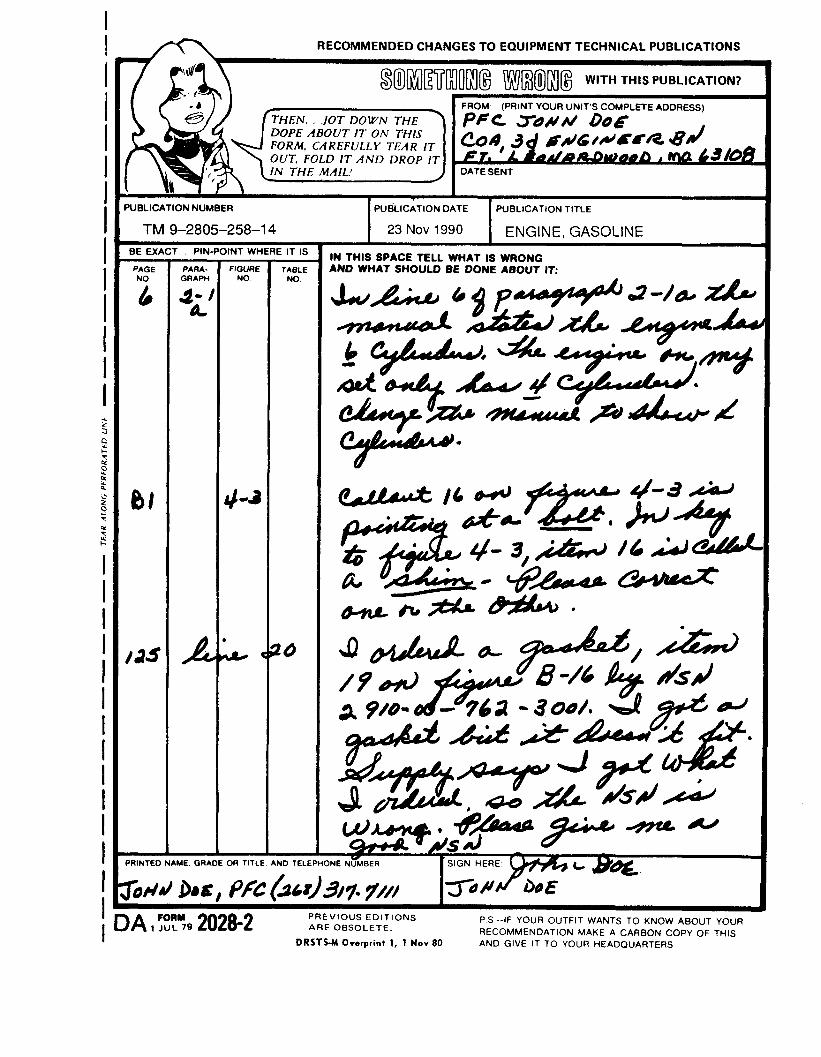

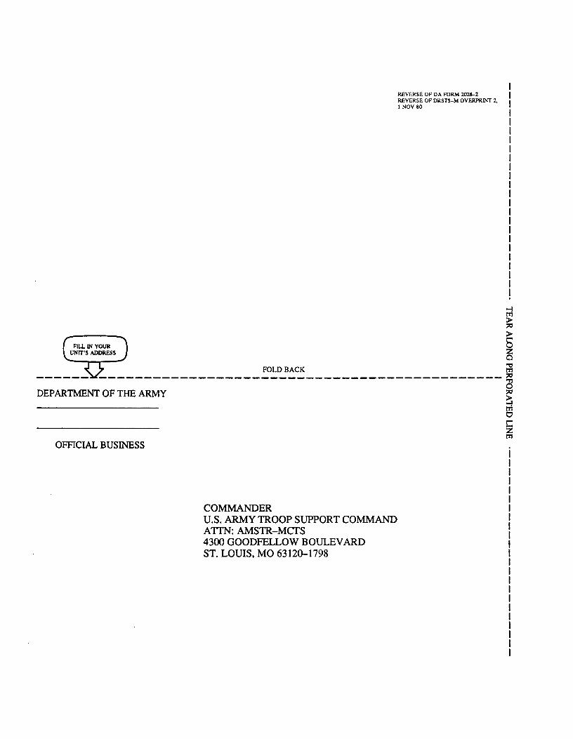
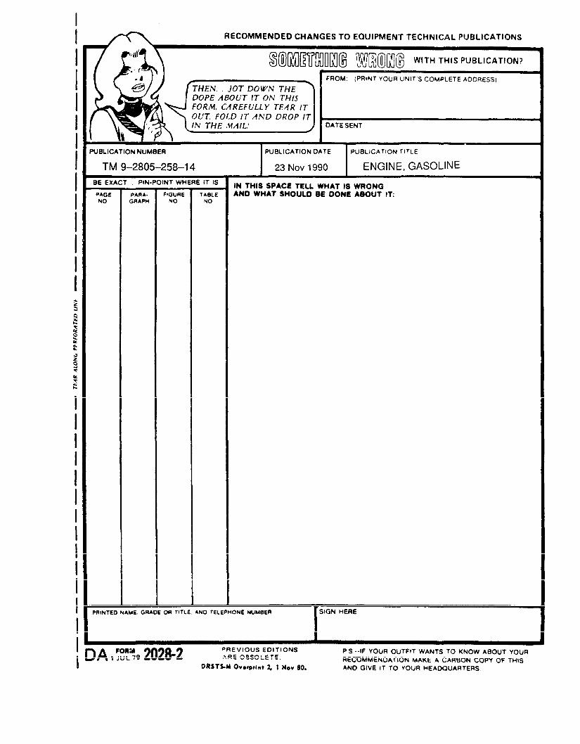
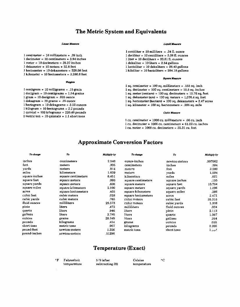

PIN: 055675-002