Embed Size (px)
Citation preview
UNIT 1
OVER VOLTAGE IN ELECTRICAL POWER SYSTEM
Causes of Over voltage in Power System
Increase in voltage for the very short time in power system is called as the over voltage. it is also
known as the voltage surge or voltage transients. The voltage stress caused by over voltage can
damage the lines and equipment’s connected to the system, There are two types of causes of over
voltage in power system.
1. Over voltage due to external causes
2. Over voltage due to internal causes
Transient over voltages can be generated at high frequency (load switching and lightning),
medium frequency (capacitor energizing), or low frequency.Over voltage due to external causes:
This cause of over voltage in power system is the lightning strokes in the cloud.
Now, how lightning strokes are produced. So when electric charges get accumulated in clouds
due to thunder Strom caused due to some bad atmosphere process.
This type of over voltages originates from atmospheric disturbances, mainly due to lightning.
This takes the form of a surge and has no direct relationship with the operating voltage of the
line.
It may be due to any of the following causes:
A) Direct lightning stroke
B) Electromagnetically induced over voltages due to lightning discharge taking place near the
line, called ‘side stroke’.
C) Voltages induced due to atmospheric changes along the length of the line.
D) Electrostatically induced voltages due to presence of charged clouds nearby.
E) Electrostatically induced over voltages due to the frictional effects of small particles like dust
or dry snow in the atmosphere or due to change in the altitude of the line.
The potential between the clouds and earth breaks down and lightning flash takes place between
the cloud and ground when this voltage becomes 5 to 20 million volts or when the potential
gradient becomes 5000V to 10000V per cm.
There are two types of lightning strokes.
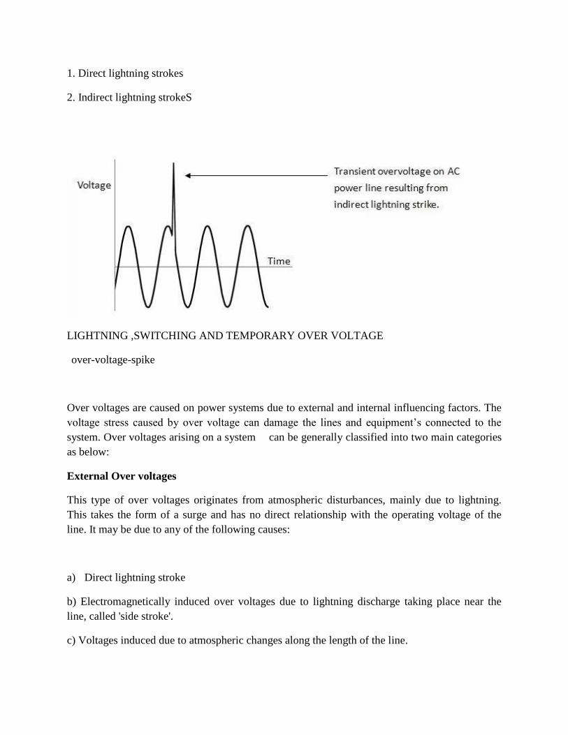
1. Direct lightning strokes
2. Indirect lightning strokeS
LIGHTNING ,SWITCHING AND TEMPORARY OVER VOLTAGE
over-voltage-spike
Over voltages are caused on power systems due to external and internal influencing factors. The
voltage stress caused by over voltage can damage the lines and equipment’s connected to the
system. Over voltages arising on a system can be generally classified into two main categories
as below:
External Over voltages
This type of over voltages originates from atmospheric disturbances, mainly due to lightning.
This takes the form of a surge and has no direct relationship with the operating voltage of the
line. It may be due to any of the following causes:
a) Direct lightning stroke
b) Electromagnetically induced over voltages due to lightning discharge taking place near the
line, called 'side stroke'.
c) Voltages induced due to atmospheric changes along the length of the line.

d) Electrostatically induced voltages due to presence of charged clouds nearby.
e) Electrostatically induced over voltages due to the frictional effects of small particles like dust
or dry snow in the atmosphere or due to change in the altitude of the line.
Internal Over voltages
These over voltages are caused by changes in the operating conditions of the power system.
These can be divided into two groups as below:
1. Switching over voltages or Transient over operation voltages of high frequency:
This is caused when switching operation is carried out under normal conditions or when fault
occurs in the network. When an unloaded long line is charged, due to Ferranti Effect the
receiving end voltage is increased considerably resulting in over voltage in the system.
Similarly when the primary side of the transformers or reactors is switched on, over voltage of
transient nature occurs.
2. Temporary over voltages:
These are caused when some major load gets disconnected from the long line under normal or
steady state condition.
EFFECTS OF OVER VOLTAGES ON POWER SYSTEMS
Over voltage tends to stress the insulation of the electrical equipment’s and likely to cause
damage to them when it frequently occurs. Over voltage caused by surges can result in spark
over and flash over between phase and ground at the weakest point in the network, breakdown of
gaseous/solid/ liquid insulation, failure of transformers and rotating machines.
Overvoltage Protection
There are always a chance of suffering an electrical power system from abnormal over voltages.
These abnormal over voltages may be caused due to various reason such as, sudden interruption
of heavy load, lightening impulses, switching impulses etc. These over voltage stresses may
damage insulation of various equipments and insulators of the power system. Although, all the
over voltage stresses are not strong enough to damage insulation of system, but still these over
voltages also to be avoided to ensure the smooth operation of electrical power system.
These all types of destructive and non destructive abnormal over voltages are eliminated from
the system by means of overvoltage protection.
Voltage Surge
The over voltage stresses applied upon the power system, are generally transient in nature.
Transient voltage or voltage surge is defined as sudden sizing of voltage to a high peak in very
short duration.The voltage surges are transient in nature, that means they exist for very short
duration. The main cause of these voltage surges in power system are due to lightning impulses
and switching impulses of the system. But over voltage in the power system may also be caused
by, insulation failure, arcing ground and resonance etc.
The voltage surges appear in the electrical power system due to switching surge, insulation
failure, arcing ground and resonance are not very large in magnitude. These over voltages hardly
cross the twice of the normal voltage level. Generally, proper insulation to the different
equipment of power system is sufficient to prevent any damage due to these over voltages. But
over voltages occur in the power system due to lightning is very high. If over voltage protection
is not provided to the power system, there may be high chance of severe damage. Hence all over
voltage protection devices used in power system mainly due to lightning surges.
Switching Impulse or Switching Surge
When a no load transmission line is suddenly switched on, the voltage on the line becomes twice
of normal system voltage. This voltage is transient in nature. When a loaded line is suddenly
switched off or interrupted, voltage across the line also becomes high enough current chopping
in the system mainly during opening operation of air blast circuit breaker, causes over voltage in
the system. During insulation failure, a live conductor is suddenly earthed. This may also caused
sudden over voltage in the system. If emf wave produced by alternator is distorted, the trouble of
resonance may occur due to 5th or higher harmonics. Actually for frequencies of 5th or higher
harmonics, a critical situation in the system so appears, that inductive reactance of the system
becomes just equal to capacitive reactance of the system. As these both reactance cancel each
other the system becomes purely resistive. This phenomenon is called resonance and at
resonance the system voltage may be increased enough.
But all these above mentioned reasons create over voltages in the system which are not very high
in magnitude.
But over voltage surges appear in the system due to lightning impulses are very high in
amplitude and highly destructive. The affect of lightning impulse hence must be avoided for over
voltage protection of power system.
Methods of Protection Against Lightning
These are mainly three main methods generally used for protection against lightning. They are

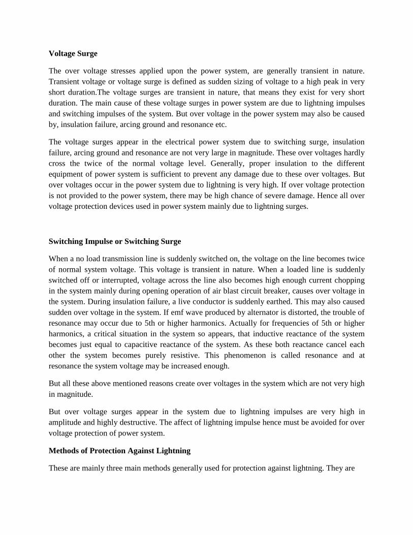
Earthing screen.
Overhead earth wire.
Lighning arrester or surge dividers.
Earthing Screen
Earthing screen is generally used over electrical substation. In this arrangement a net of GI wire
is mounted over the sub-station. The GI wires, used for earthing screen are properly grounded
through different sub-station structures. This network of grounded GI wire over electrical
sub-station, provides very low resistance path to the ground for lightning strokes.
This method of high voltage protection is very simple and economic but the main drawback is, it
can not protect the system from travelling wave which may reach to the sub-station via different
feeders.
Overhead Earth Wire
This method of over voltage protection is similar as earthing screen. The only difference is, an
earthing screen is placed over an electrical sub-station, whereas, overhead earth wire is placed
over electrical transmission network. One or two stranded GI wires of suitable cross-section are
placed over the transmission conductors. These GI wires are properly grounded at each
transmission tower. These overhead ground wires or earth wire divert all the lightning strokes to
the ground instead of allowing them to strike directly on the transmission conductors.
Lightning Arrester
The previously discussed two methods, i.e. earthing screen and over-head earth wire are very
suitable for protecting an electrical power system from directed lightning strokes but system
from directed lightning strokes but these methods can not provide any protection against high
voltage travelling wave which may propagate through the line to the equipment of the
sub-station.The lightning arrester is a devices which provides very low impedance path to the
ground for high voltage travelling waves.
The concept of a lightning arrester is very simple. This device behaves like a nonlinear electrical
resistance. The resistance decreases as voltage increases and vice-versa, after a certain level of
voltage.The functions of a lightning arrester or surge dividers can be listed as below.
Under normal voltage level, these devices withstand easily the system voltage as electrical
insulator and provide no conducting path to the system current.
On occurrence of voltage surge in the system, these devices provide very low impedance path for
the excess charge of the surge to the ground.
After conducting the charges of surge, to the ground, the voltage becomes to its normal level.
Then lightning arrester regains its insulation properly and prevents regains its insulation property
and prevents further conduction of current, to the ground.
There are different types of lightning arresters used in power system, such as rod gap arrester,
horn gap arrester, multi-gap arrester, expulsion type LA, value type LA. In addition to these the
most commonly used lightning arrester for over voltage protection now-a-days gapless ZnO
lightning arrester is also used.
INSULATION COORDINATION
Insulation Coordination in Power System was introduced to arrange the electrical insulation
levels of different components in the electrical power system including transmission network, in
such a manner, that the failure of insulator, if occurs, confindes to the place where it would result
in the least danmage of the system, easy to repair and replace, and results least disturbance to the
power supply.
When any over voltage appears in the electrical power system, then there may be a chance of
failure of its insulation system. Probability of failure of insulation, is high at the weakest
insulation point nearest to the source of over voltage. In power system and transmission
networks, insulation is provided to the all equipment and components.
Insulators in some points are easily replaceable and repairable compared to other. Insulation in
some points are not so easily replaceable and repairable and the replacement and repairing may
be highly expensive and require long interruption of power. Moreover failure of insulator at
these points may causes bigger part of electrical network to be out of service. So, it is desirable
that in situation of insulator failure, only the easily replaceable and repairable insulator fails. The
overall aim of insulation coordination is to reduce to an economically and operationally
acceptable level the cost and disturbance caused by insulation failure. In insulation coordination
method, the insulation of the various parts of the system must be so graded that flash over if
occurs it must be at intended points.
For proper understanding the insulation coordination we have to understand first, some basic
terminologies of the electrical power system. Let us have a discussion.
Nominal System Voltage
Nominal System Voltage is the phase to phase voltage of the system for which the system is
normally designed. Such as 11 KV, 33 KV, 132 KV, 220 KV, 400 KV systems.
Maximum System Voltage
Maximum System Voltage is the maximum allowable power frequency voltage which can occurs
may be for long time during no load or low load condition of the power system. It is also
measured in phase to phase manner.
List of different nominal system voltage and their corresponding maximum system voltage is
given below for reference,
Nominal System Voltage in KV 11 33 66 132 220 400
Maximum System Voltage in KV 12 36 72.5 145 245 420
NB - It is observed from above table that generally maximum system voltage is 110 % of
corresponding nominal system voltage up to voltage level of 220 KV, and for 400 KV and above
it is 105 %.
Factor of Earthing
This is the ratio of the highest rms phase to earth power frequency voltage on a sound phase
during an earth fault to the rms phase to phase power frequency voltage which would be obtained
at the selected location without the fault.
This ratio characterizes, in general terms, the earthing conditions of a system as viewed from the
selected fault location.
Effectively Earthed System
A system is said to be effectively earthed if the factor of earthing does not exceed 80 % and
non-effectively earthed if it does.Factor of earthing is 100 % for an isolated neutral system, while
it is 57.7 % (1/√3 = 0.577) for solidly earthed system.
Insulation Level
Every electrical equipment has to undergo different abnormal transient over voltage situation in
different times during its total service life period. The equipment may have to withstand
lightning impulses, switching impulses and/or short duration power frequency over voltages.
Depending upon the maximum level of impulse voltages and short duration power frequency
over voltages that one power system component can withstand, the insulation level of high
voltage power system is determined.
During determining the insulation level of the system rated less than 300 KV, the lightning
impulse withstand voltage and short duration power frequency withstand voltage are considered.
For equipment rated more or equal 300 KV, switching impulse withstand voltage and short
duration power frequency withstand voltage are considered.

Lightning Impulse Voltage
The system disturbances occur due to natural lightning, can be represented by three different
basic wave shapes. If a lightning impulse voltage travels some distance along the transmission
line before it reaches to a insulator its wave shaped approaches to full wave, and this wave is
referred as 1.2/50 wave. If during travelling, the lightning disturbance wave causes flash over
across an insulator the shape of the wave becomes chopped wave. If a lightning stroke hits
directly on the insulator then the lightning impulse voltage may rise steep until it is relieved by
flash over, causing sudden, very steep collapse in voltage. These three waves are quite different
in duration and in shapes.
Switching Impulse
During switching operation there may be uni-polar voltage appears in the system. The wave form
of which may be periodically damped or oscillating one. Switching impulse wave form has steep
front and long damped oscillating tale.
Short Duration Power Frequency Withstand Voltage
Short duration power frequency withstand voltage is the prescribed rms value of sinusoidal
power frequency voltage that the electrical equipment shall withstand for a specific period of
time normally 60 seconds.
Protection Level Voltage of Protective Device
Over voltage protective device like surge arrestors or lightning arrestors are designed to
withstand a certain level of transient over voltage beyond which the devices drain the surge
energy to the ground and therefore maintain the level of transient over voltage up to a specific
level. Thus transient over voltage can not exceed that level. The protection level of over voltage
protective device is the highest peak voltage value which should not be exceeded at the terminals
of over voltage protective device when switching impulses and lightening impulses are applied.

As we discussed above that a component of electrical power system may suffer from different
level of transient voltage stresses, switching impulse voltage and lightning impulse voltage. The
maximum amplitude of transient over voltages reach the components, can be limited by using
protecting device like lightning arrestors in the system. If we maintain the insulation level of all
the power system component above the protection level of protective device, then ideally there
will be no chance of breakdown of insulation of any component. Since the transient over voltage
reaches at the insulation after crossing the surge protective devices will have amplitude equals to
protection level voltage and protection level voltage impulse insulation level of the components.
Generally, the impulse insulation level is established at 15 to 25 % above the protective level
voltage of protective devices.

UNIT 2
ELECTRICAL BREAKDOWN IN GASES,SOLIDS AND LIQUIDS
GASEOUS BREAKDOWN IN UNIFORM AND NON UNIFORM FIELDS
Gases. Electrical breakdown occurs within a gas when the dielectric strength of the gas is
exceeded. ... The voltage that leads to electrical breakdown of a gas is approximated by
Paschen's Law. Partial discharge in air causes the "fresh air" smell of ozone during
thunderstorms or around high-voltage equipment
UNIFORM AND NON UNIFORM FIELDS
Electric fields are represented by drawing field lines that represent the direction of the field, as
well as the strength of the field. More field lines represents a higher field strength. In a
non-uniform electric field, the field lines tend to be curved and are more concentrated near the
charges. In a uniform electric field, since the field strength does not vary, the field lines are
parallel to each other and equally spaced. Uniform fields are created by setting up a potential
difference between two conducting plates placed at a certain distance from one another. The field
is considered to be uniform at the center of the plates, but varies close to the edge of the plates.
The strength of the field depends on the potential difference applied to the plates and the distance
by which they are separated. A higher potential difference or voltage results in a stronger electric
field. The greater the distance between the plates, the weaker the field becomes. The electric
field is therefore calculated as a ratio of the voltage between the plates to the distance they are
separated by THEM.
CORONA DISCHARGE
A corona discharge is an electrical discharge brought on by the ionization of a fluid such as air
surrounding a conductor that is electrically charged. Spontaneous corona discharges occur
naturally in high-voltage systems unless care is taken to limit the electric field strength. A corona
will occur when the strength (potential gradient) of the electric field around a conductor is high
enough to form a conductive region, but not high enough to cause electrical breakdown or arcing
to nearby objects. It is often seen as a bluish (or other color) glow in the air adjacent to pointed
metal conductors carrying high voltages, and emits light by the same property as a gas discharge
lamp.

In many high voltage applications corona is an unwanted side effect. Corona discharge from high
voltage electric power transmission lines constitutes an economically significant waste of energy
for utilities. In high voltage equipment like televisions, radio transmitters, X-ray machines and
particle accelerators the current leakage caused by coronas can constitute an unwanted load on
the circuit. In air, coronas generate gases such as ozone (O3) and nitric oxide (NO), and in turn
nitrogen dioxide (NO2), and thus nitric acid (HNO3) if water vapor is present. These gases are
corrosive and can degrade and embrittle nearby materials, and are also toxic to people. Corona
discharges can often be suppressed by improved insulation, corona rings, and making high
voltage electrodes in smooth rounded shapes. However, controlled corona discharges are used in
a variety of processes such as air filtration, photocopiers and ozone generators.
VACCUM BREAKDOWN
Experiments have been performed in order to get information about the phenomena preceding
the electrical breakdown in small vacuum gaps. Most experiments have been made with impulse
voltages of different rise times; some complementary results obtained with alternating voltage
are also presented. The effect of surface layers on the breakdown voltage and on the
pre-breakdown current is discussed. It has been found that the rise time of the voltage affects
both the breakdown voltage and the pre-breakdown current. The experiments seem to indicate
that breakdown in the underlying circumstances is the result of a discharge in metal vapour,
originating from the anode. The vapour is thought to be generated by the heating of the anode by
a bombardment of field-emission electrons. The transition of the pre-breakdown current to a
sudden discharge may occur when the vapour density passes a critical value.
§ 1. Introduction.
The mechanism of the electrical breakdown
in vacuum has been the subject of many investigations. Generally, field emission of electrons is
accepted as the first step in the process. Different explanations have to be given for the
breakdown of small gaps (< 1 mm) and for the high-voltage breakdown of large gaps,
since it has been found that the breakdown field strength decreases considerably with increasing
gap length. The pre-breakdown current introducing the discharge should therefore be much
smaller in large gaps than in small ones. A few hypotheses with regard to the development of the
discharge will be briefly mentioned here. Except for assumption e), breakdown is thought to
occur as a result of some multiplication process in metallic vapour produced at one of the
electrodes:
a) Evaporation of the anode surface is caused by a bombardment by field-emission electrons
breakdown mechanisms in solid and composite dielectrics
Solid dielectric materials are used in all kinds of electrical circuits and devices to insulate one

current carrying part from another when they operate at different voltages. A good dielectric
should have low dielectric loss, high mechanical strength, should be free from gaseous inclusion,
and moisture, and be resistant to thermal and chemical deterioration. Solid dielectrics have
higher breakdown strength compared to liquids and gases.
Studied of the breakdown of solid dielectrics are of extreme importance in insulation studies.
When breakdown occurs, solids get permanently damaged while gases fully and liquids partly
recover their dielectric strength after the applied electric field removed.
The mechanism of breakdown is a complex phenomenon in the case of solids, and varies
depending on the time of application of voltage as shown in Fig.
4. 1. The various breakdown mechanisms can be classifiedINTRINSIC BREAKDOWN
When voltages are applied only for short durations of the order of 8 10 sthe dielectric strength of
a solid dielectric increases very rapidly to an upper limit called the intrinsic electric strength.
Experimentally, this highest dielectric strength can be obtained only under the best experimental
conditions when all extraneous influences have been isolated and the value depends only on the
structure of the material and the temperature. The maximum electrical strength recorder is 15
MV/cm for polyvinyl-alcohol at -1960 C. The maximum strength usually obtainable ranges from
5 MV/cm. Intrinsic breakdown depends upon the presence of free electrons which are capable of
migration through the lattice of the dielectric. Usually, a small number of conduction electrons
are present in solid dielectrics, along with some structural imperfections and small amounts of
impurities. The impurity atoms, or molecules or both act as traps for the conduction electrons up
to certain ranges of electric fields and temperatures. When these ranges are exceeded, additional
electrons in addition to trapped electrons are released, and these electrons participate in the
conduction process. Based on this principle, two types of intrinsic breakdown mechanisms have
been proposed.
i) Electronic Breakdown
Intrinsic breakdown occurs in time of the order of 10-8 s and therefore is assumed to be
electronic in nature. The initial density of conduction (free) electrons is also assumed to be large,
and electron-electron collisions occur. When an electric field is applied, electrons gain energy
from the electric field and cross the forbidden energy gap from the valence band to the
conduction band. When this process is repeated, more and more electrons become available in
the conduction band, eventually leading to breakdown.
ii) Avalanche or Streamer Breakdown
This is similar to breakdown in gases due to cumulative ionization. Conduction electrons gain
sufficient energy above a certain critical electric field and cause liberation of electrons from the
lattice atoms by collision. Under uniform field conditions, if the electrodes are embedded in the
specimen, breakdown will occur when an electron avalanche bridges the electrode gap. An
electron within the dielectric, starting from the cathode will drift towards the anode and during
this motion gains energy from the field and loses it during collisions. When the energy gained by
an electron exceeds the lattice ionization potential, an additional electron will be liberated due to
collision of the first electron.
Unit 3
Generation of high voltage and current
Generation of high d.c. voltages is mainly required in research work in the areas of pure and
applied physics. Sometimes, high direct voltages are needed in insulation tests on cables and
capacitors. Impulse generator charging units also require high d.c. voltages of about 100 to 200
kV. Normally, for the generation of d.c. voltages of up to 100 kV, electronic valve rectifiers are
used and the output currents are about 100 mA. The rectifier valves require special construction
for cathode and filaments since a high electrostatic field of several kV/cm exist between the
anode and the cathode in the nonconduction period. The a.c. supply to the rectifier tubes may be
of power frequency or may be of audio frequency from an oscillator. The latter is used when a
ripple of very small magnitude is required without the use of costly filters to smoothen the ripple.
Half and Full Wave Rectifier Circuits
Rectifier circuits for producing high d.c. voltages from a.c. sources may be
(a) halfwave,
(b) full wave, or
(c) voltage doubler type rectifiers.
The rectifier may be an electron tube or a solid state device. Nowadays single electron tubesare
available for peak inverse voltages up to 250 kV, and semiconductor or solid state diodesup to 20
kV. For higher voltages, several units are to be used in series. When a number ofunits are used in
series, transient voltage distribution along each unit becomes non-uniformand special care should
be taken to make the distribution uniform. Commonly used half waveand full wave rectifiers
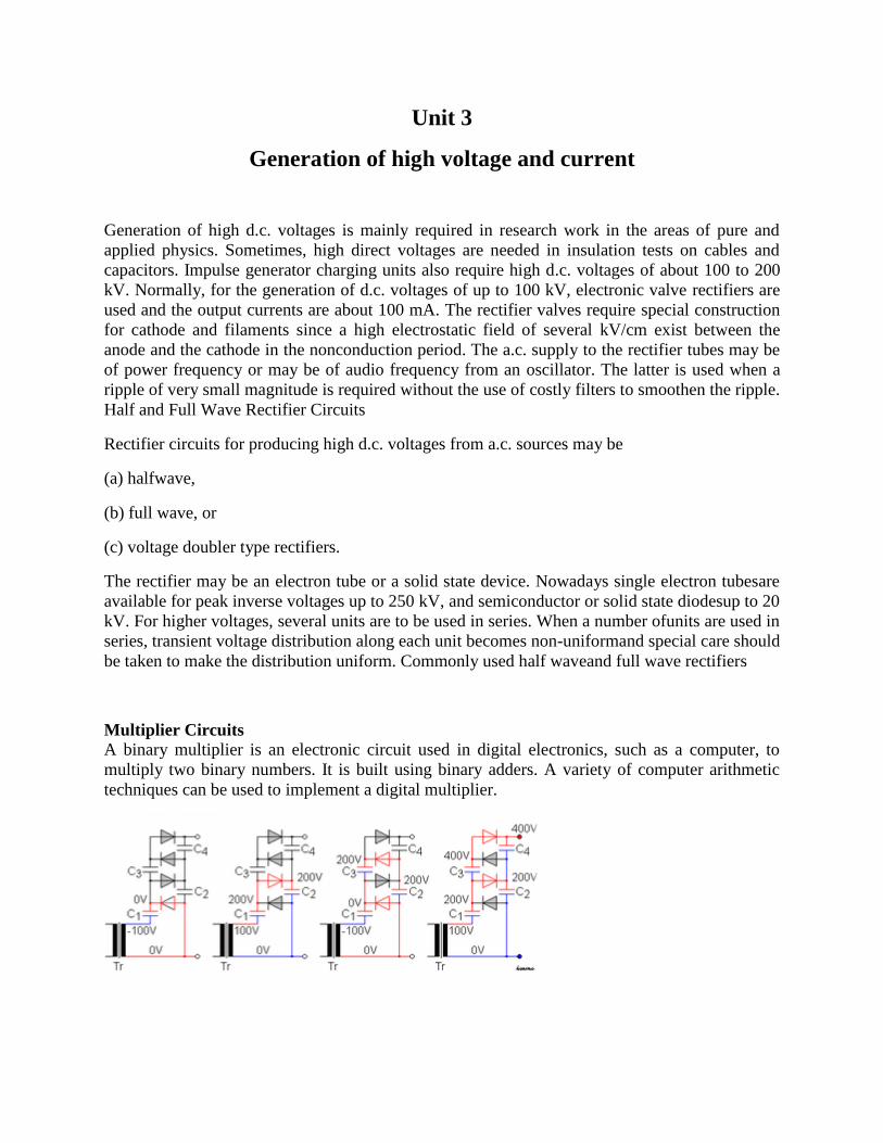
Multiplier Circuits
A binary multiplier is an electronic circuit used in digital electronics, such as a computer, to
multiply two binary numbers. It is built using binary adders. A variety of computer arithmetic
techniques can be used to implement a digital multiplier.

Assuming that the peak voltage of the AC source is +Us, and that the C values are sufficiently
high to allow, when charged, that a current flows with no significant change in voltage, then the
(simplified) working of the cascade is as follows:
Illustration of the described operation, with +us = 100v
Negative peak (−us): the c1 capacitor is charged through diode d1 to us v (potential difference
between left and right plate of the capacitor is us)
Positive peak (+us): the potential of c1 adds with that of the source, thus charging c2 to 2us
through d2
Negative peak: potential of c1 has dropped to 0 v thus allowing c3 to be charged through d3 to
2us.
Positive peak: potential of c2 rises to 2us (analogously to step 2), also charging c4 to 2us. The
output voltage (the sum of voltages under c2 and c4) rises until 4us is reached.
In reality more cycles are required for c4 to reach the full voltage. Each additional stage of two
diodes and two capacitors increases the output voltage by twice the peak ac supply voltage.
Van de graff generator
A Van de Graaff generator is an electrostatic generator which uses a moving belt to accumulate
electric charge on a hollow metal globe on the top of an insulated column, creating very high
electric potentials. It produces very high voltage direct current (DC) electricity at low current
levels. It was invented by American physicist Robert J. Van de Graaff during 1929.[1] The
potential difference achieved by modern Van de Graaff generators can be as much as 5
megavolts. A tabletop version can produce on the order of 100,000 volts and can store enough
energy to produce a visible spark. Small Van de Graaff machines are produced for entertainment,
and for physics education to teach electrostatics; larger ones are displayed in some science
museums.
The Van de Graaff generator was developed as a particle accelerator for physics research, its
high potential is used to accelerate subatomic particles to great speeds in an evacuated tube. It
was the most powerful type of accelerator of the 1930s until the cyclotron was developed. Van
de Graaff generators are still used as accelerators to generate energetic particle and x-ray beams
for nuclear medicine research. In order to double the voltage, two generators are often used
together, one generating positive and the other negative potential; this is termed a tandem Van de
Graaff accelerator. For example, the Brookhaven National Laboratory Tandem Van de Graaff
achieves about 30 million volts of potential difference.
The voltage produced by an open-air Van de Graaff machine is limited by arcing and corona
discharge to about 5 megavolts. Most modern industrial machines are enclosed in a pressurized
tank of insulating gas; these can achieve potentials of as much as about 25 megavolts.
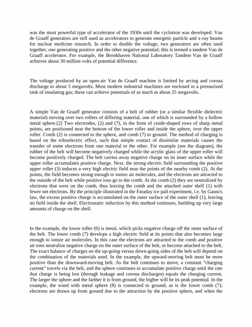
A simple Van de Graaff generator consists of a belt of rubber (or a similar flexible dielectric
material) moving over two rollers of differing material, one of which is surrounded by a hollow
metal sphere.[2] Two electrodes, (2) and (7), in the form of comb-shaped rows of sharp metal
points, are positioned near the bottom of the lower roller and inside the sphere, over the upper
roller. Comb (2) is connected to the sphere, and comb (7) to ground. The method of charging is
based on the triboelectric effect, such that simple contact of dissimilar materials causes the
transfer of some electrons from one material to the other. For example (see the diagram), the
rubber of the belt will become negatively charged while the acrylic glass of the upper roller will
become positively charged. The belt carries away negative charge on its inner surface while the
upper roller accumulates positive charge. Next, the strong electric field surrounding the positive
upper roller (3) induces a very high electric field near the points of the nearby comb (2). At the
points, the field becomes strong enough to ionize air molecules, and the electrons are attracted to
the outside of the belt while positive ions go to the comb. At the comb (2) they are neutralized by
electrons that were on the comb, thus leaving the comb and the attached outer shell (1) with
fewer net electrons. By the principle illustrated in the Faraday ice pail experiment, i.e. by Gauss's
law, the excess positive charge is accumulated on the outer surface of the outer shell (1), leaving
no field inside the shell. Electrostatic induction by this method continues, building up very large
amounts of charge on the shell.
In the example, the lower roller (6) is metal, which picks negative charge off the inner surface of
the belt. The lower comb (7) develops a high electric field at its points that also becomes large
enough to ionize air molecules. In this case the electrons are attracted to the comb and positive
air ions neutralize negative charge on the outer surface of the belt, or become attached to the belt.
The exact balance of charges on the up-going versus down-going sides of the belt will depend on
the combination of the materials used. In the example, the upward-moving belt must be more
positive than the downward-moving belt. As the belt continues to move, a constant "charging
current" travels via the belt, and the sphere continues to accumulate positive charge until the rate
that charge is being lost (through leakage and corona discharges) equals the charging current.
The larger the sphere and the farther it is from ground, the higher will be its peak potential. In the
example, the wand with metal sphere (8) is connected to ground, as is the lower comb (7);
electrons are drawn up from ground due to the attraction by the positive sphere, and when the
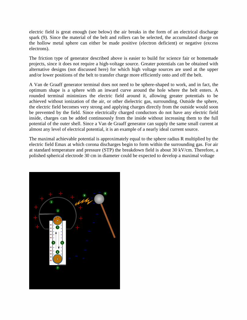
electric field is great enough (see below) the air breaks in the form of an electrical discharge
spark (9). Since the material of the belt and rollers can be selected, the accumulated charge on
the hollow metal sphere can either be made positive (electron deficient) or negative (excess
electrons).
The friction type of generator described above is easier to build for science fair or homemade
projects, since it does not require a high-voltage source. Greater potentials can be obtained with
alternative designs (not discussed here) for which high voltage sources are used at the upper
and/or lower positions of the belt to transfer charge more efficiently onto and off the belt.
A Van de Graaff generator terminal does not need to be sphere-shaped to work, and in fact, the
optimum shape is a sphere with an inward curve around the hole where the belt enters. A
rounded terminal minimizes the electric field around it, allowing greater potentials to be
achieved without ionization of the air, or other dielectric gas, surrounding. Outside the sphere,
the electric field becomes very strong and applying charges directly from the outside would soon
be prevented by the field. Since electrically charged conductors do not have any electric field
inside, charges can be added continuously from the inside without increasing them to the full
potential of the outer shell. Since a Van de Graaff generator can supply the same small current at
almost any level of electrical potential, it is an example of a nearly ideal current source.
The maximal achievable potential is approximately equal to the sphere radius R multiplied by the
electric field Emax at which corona discharges begin to form within the surrounding gas. For air
at standard temperature and pressure (STP) the breakdown field is about 30 kV/cm. Therefore, a
polished spherical electrode 30 cm in diameter could be expected to develop a maximal voltage

High Alternating Voltage Generator Using Cascade Transformers
The above Figure shows the cascade transformer units in which the first transformer is at the
ground potential along with its tank. The second transformer is kept on insulators and
maintained at a potential of V2, the output voltage of the first unit above the ground. The
high voltage winding of the first unit is connected to the tank of the second unit. The low
voltage winding of this unit is supplied from the excitation winding of the first transformer,
which is in series with the high voltage winding of the first transformer at its high voltage
end. The rating of the excitation windings is almost identical to that of the primary or the low
or the low voltage winding. The high voltage connection from the first transformer winding
and the excitation winding terminal are taken through a bushing to the second transformer. In
a similar manner, the third transformer is kept on insulators above the ground at a potential of
2V2 and is supplied likewise from the second transformer. The number of stages in this type
of arrangement are usually two four, but very often, three stages are adapted to facilitate a

three-phase operation so that3V 2 can be obtained between the lines. Supply to the units can
be obtained from a motor-generator set or through an induction regulstor for variation of the
output voltage. The rating of the primary or the low voltage windings is usually 230 or 400 V
for small units up to 100 kVA. For larger outputs the rating of the low voltage winding may
be 3.3 kV, 6.6kV or 11 kV.
Production Of High Frequency Ac High Voltage
The power systems engineers is interested in high voltages primarily for power transmission, and
secondly for testing of his equipment used in power transmission. In this chapter we are
interested in generating high voltages for testing of insulation. Thus generation has to be carried
out in the testing laboratory. In many testing laboratories, the primary source of power is at low
voltage (400 V three phase or 230 V single phase, at 50 Hz). Thus we need to be able to obtain
the high voltage from this. Since insulation is usually being tested, the impedances involved are
extremely high (order of M_____ _ rents small (less than an ampere). Therefore high voltage
testing does not usually require high power. Thus special methods may be used which are not
applicable when generating high voltage in high power applications.
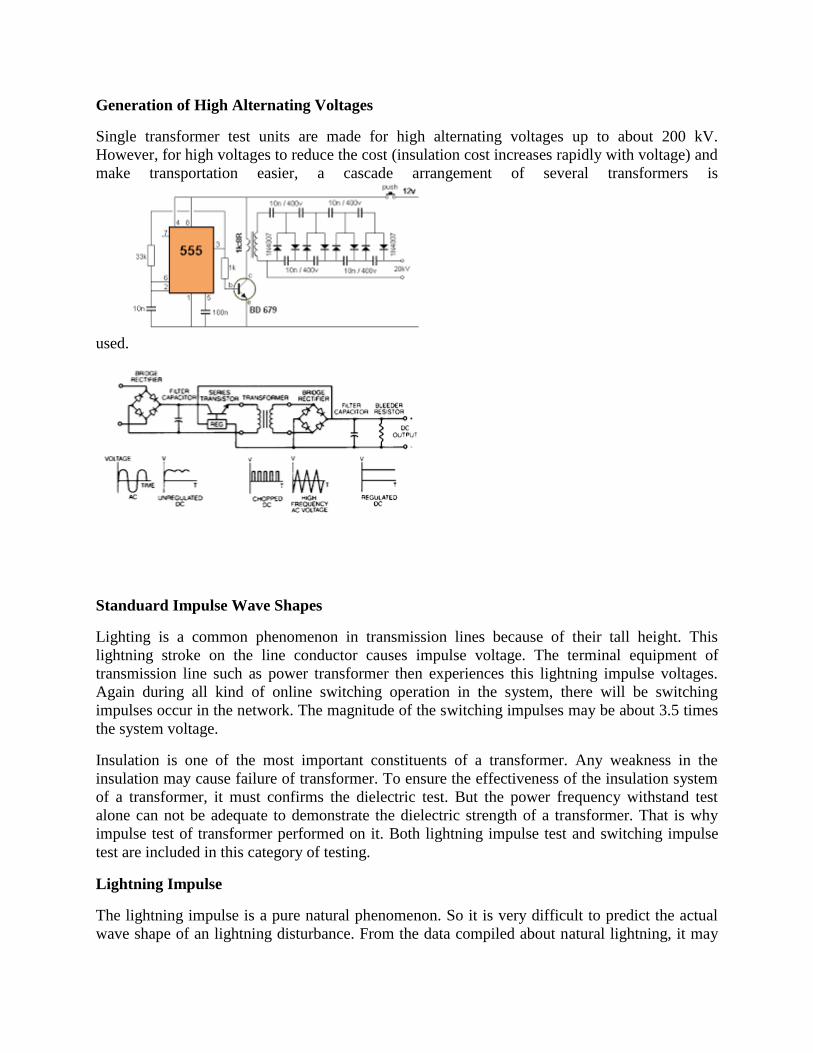
Generation of High Alternating Voltages
Single transformer test units are made for high alternating voltages up to about 200 kV.
However, for high voltages to reduce the cost (insulation cost increases rapidly with voltage) and
make transportation easier, a cascade arrangement of several transformers is
used.
Standuard Impulse Wave Shapes
Lighting is a common phenomenon in transmission lines because of their tall height. This
lightning stroke on the line conductor causes impulse voltage. The terminal equipment of
transmission line such as power transformer then experiences this lightning impulse voltages.
Again during all kind of online switching operation in the system, there will be switching
impulses occur in the network. The magnitude of the switching impulses may be about 3.5 times
the system voltage.
Insulation is one of the most important constituents of a transformer. Any weakness in the
insulation may cause failure of transformer. To ensure the effectiveness of the insulation system
of a transformer, it must confirms the dielectric test. But the power frequency withstand test
alone can not be adequate to demonstrate the dielectric strength of a transformer. That is why
impulse test of transformer performed on it. Both lightning impulse test and switching impulse
test are included in this category of testing.
Lightning Impulse
The lightning impulse is a pure natural phenomenon. So it is very difficult to predict the actual
wave shape of an lightning disturbance. From the data compiled about natural lightning, it may

be concluded that the system disturbance due to natural lightning stroke, can be represented by
three basic wave shapes.
Full wave
Chopped wave and
Front of wave
Although the actual lightning impulse disturbance may not have exactly these three shapes but
by defining these waves one can establish a minimum impulse dielectric strength of a
transformer.
If lighting disturbance travels some distance along the transmission line before it reaches the
transformer, its wave shape may approach to full wave.
If during traveling, if flash-over occurs at any insulator of the transmission line, after the peak of
the wave has been reached, the wave may become in form of chopped wave.
If the lightning stroke directly hits the transformer terminals, the impulse voltage rises rapidly
until it is relieved by a flash over. At the instant of flash-over the voltage suddenly collapses and
may form the front of wave shape.
The effect of these wave forms on the transformer insulation may be different from each other.
We are not going here in detail discussion of what type of impulse voltage wave forms causes
what type of failure in transformer. But whatever may be the shape of lightning disturbance
voltage wave, all of them can cause insulation failure in transformer. So lighting impulse test of
transformer is one of the most important type test of transformer.
Switching Impulse
Through studies and observations reveal that the switching over voltage or switching impulse
may have front time of several hundred microseconds and this voltage may be periodically
damped out. The IEC - 600060 has adopted for their switching impulse test, a long wave having
front time 250 μs and time to half value 2500 μs with tolerances. The purpose of the impulse
voltage test is to secure that the transformer insulation withstand the lightning overvoltage which
may occur in service. Impulse test The impulse generator design is based on the Marx circuit.
The basic circuit diagram is shown on Figure above. The impulse capacitors Cs (12 capacitors of
750 ηF) are charged in parallel through the charging resistors Rc (28 kΩ) (highest permissible
charging voltage 200 kV). When the charging voltage has reached the required value, breakdown
of the spark gap F1 is initiated by an external triggering pulse. When F1 breaks down, the
potential of the following stage (point B and C) rises. Because the series resistors Rs is of
low-ohmic value compared with the discharging resistors Rb (4,5 kΩ) and the charging resistor
Rc, and since the low-ohmic discharging resistor Ra is separated from the circuit by the auxiliary
spark-gap Fal, the potential difference across the spark-gap F2 rises considerably and the
breakdown of F2 is initiated.
Thus the spark-gaps are caused to break down in sequence. Consequently the capacitors are
discharged in series-connection. The high-ohmic discharge resistors Rb are dimensioned for
switching impulses and the low-ohmic resistors Ra for lightning impulses. The resistors Ra are
connected in parallel with the resistors Rb, when the auxiliary spark-gaps break down, with a
time delay of a few hundred nano-seconds.
The arrangement is necessary in order to secure the functioning of the generator.
The wave shape and the peak value of the impulse voltage are measured by means of an Impulse
Analysing System (DIAS 733) which are connected to the voltage divider. The required voltage
is obtained by selecting a suitable number of series-connected stages and by adjusted the
charging voltage. In order to obtain the necessary discharge energy parallel or series-parallel
connections of the generator can be used. In these cases some of the capacitors are connected in
parallel during the discharge.
The required impulse shape is obtained by suitable selection of the series and discharge resistors
of the generator.
The front time can be calculated approximately from the equation:
For R1 >> R2 and Cg >> C (15.1)
Tt = .R.C.123
and the half time to half value from the equation
T ≈ 0,7.R.C
In practice the testing circuit is dimensioned according to experience.
Performance of Impulse Test
Impulse test The test is performed with standard lightning impulses of negative polarity. The
front time (T1) and the time to half-value (T2) are defined in accordance with the standard.
Standard lightning impulse
Front time T1 = 1,2 μs ± 30%
Time to half-value T2 = 50 μs ± 20%
In practice the impulse shape may deviate from the standard impulse when testing low-voltage
windings of high rated power and windings of high input capacitance. The impulse test is
performed with negative polarity voltages to avoid erratic flash overs in the external insulation
and test circuit. Waveform adjustments are necessary for most test objects. Experience gained
from results of tests on similar units or eventual pre-calculation can give guidance for selecting
components for the wave shaping circuit.
The test sequence consists of one reference impulse (RW) at 75% of full amplitude followed by
the specified number of voltage applications at full amplitude (FW) (according to IEC 60076-3
three full impulses). The equipment for voltage and current signal recording consists of digital
transient recorder, monitor, computer, plotter and printer. The recordings at the two levels can be
compared directly for failure indication. For regulating transformers one phase is tested with the

on-load tap changer set for the rated voltage and the two other phases are tested in each of the
extreme positions.
The circuit generates a high-voltage pulse by charging a number of capacitors in parallel, then
suddenly connecting them in series. See the circuit above. At first, n capacitors (C) are charged
in parallel to a voltage VC by a high-voltage DC power supply through the resistors (RC). The
spark gaps used as switches have the voltage VC across them, but the gaps have a breakdown
voltage greater than VC, so they all behave as open circuits while the capacitors charge. The last
gap isolates the output of the generator from the load; without that gap, the load would prevent
the capacitors from charging. To create the output pulse, the first spark gap is caused to break
down (triggered); the breakdown effectively shorts the gap, placing the first two capacitors in
series, applying a voltage of about 2VC across the second spark gap.[2] Consequently, the
second gap breaks down to add the third capacitor to the "stack", and the process continues to
sequentially break down all of the gaps. The last gap connects the output of the series "stack" of
capacitors to the load. Ideally, the output voltage will be nVC, the number of capacitors times the
charging voltage, but in practice the value is less. Note that none of the charging resistors Rc are
subjected to more than the charging voltage even when the capacitors have been erected. The
charge available is limited to the charge on the capacitors, so the output is a brief pulse as the
capacitors discharge through the load (and charging resistors). At some point, the spark gaps stop
conducting, and the high-voltage supply begins charging the capacitors again.
The principle of multiplying voltage by charging capacitors in parallel and discharging them in

series is also used in the voltage multiplier circuit, used to produce high voltages for laser
printers and cathode ray tube television sets, which has similarities to this circuit. The difference
is that the voltage multiplier is powered with alternating current and produces a steady DC
output voltage, while the Marx generator produces a pulse.
Marx generator used for testing high-voltage power-transmission components at TU Dresden,
Germany Marx generator at utility trade fair, Leipzig, East Germany, 1954 Marx generator
(standing rectangular structure, left) in high-voltage lab at Jabalpur Engineering College,
Jabalpur, India 600 kV 10-stage Marx generator in operation Optimization
To deliver 5 ns rise time pulses, the Marx generator is often built into a coaxial wave guide. The
spark gaps are placed as close as possible together for maximum UV light exchange for
minimum jitter. DC HV comes from underneath, pulsed HV leaves at the top into the coaxial
line. The double line of spheres in the middle are the spark gaps, all other spheres are to avoid
corona discharge. Blue=water capacitor. Grey=solid metal. Black= thin wire. The outer
conductor also functions as a vessel, so that the gas and the pressure can be optimized.
Proper performance depends upon selection of capacitor and the timing of the discharge.
Switching times can be improved by doping of the electrodes with radioactive isotopes caesium
137 or nickel 63, and by orienting the spark gaps so that ultraviolet light from a firing spark gap
switch illuminates the remaining open spark gaps.[3] Insulation of the high voltages produced is
often accomplished by immersing the Marx generator in transformer oil or a high pressure
dielectric gas such as sulfur hexafluoride (SF6).
Note that the less resistance there is between the capacitor and the charging power supply, the
faster it will charge. Thus, in this design, those closer to the power supply will charge quicker
than those farther away. If the generator is allowed to charge long enough, all capacitors will
attain the same voltage.
In the ideal case, the closing of the switch closest to the charging power supply applies a voltage
2V to the second switch. This switch will then close, applying a voltage 3V to the third switch.
This switch will then close, resulting in a cascade down the generator that produces nV at the
generator output (again, only in the ideal case).
The first switch may be allowed to spontaneously break down (sometimes called a self break)
during charging if the absolute timing of the output pulse is unimportant. However, it is usually
intentionally triggered once all the capacitors in the Marx bank have reached full charge, either
by reducing the gap distance, by pulsing an additional trigger electrode (such as a Trigatron), by
ionising the air in the gap using a pulsed laser, or by reducing the air pressure within the gap.
The charging resistors, Rc, need to be properly sized for both charging and discharging. They are

sometimes replaced with inductors for improved efficiency and faster charging. In many
generators the resistors are made from plastic or glass tubing filled with dilute copper sulfate
solution. These liquid resistors overcome many of the problems experienced by
more-conventional solid resistive materials, which have a tendency to lower their resistance over
time under high voltage conditions.
generation of switching surgesSwitching surge generators of different types are needed for the
study of the impact of oscillating switching surge in power systems. This chapter deals with the
details of the various types of switching impulse voltage generators, that is, standard switching
impulse voltage generator, unipolar-damped OSS generator and damped OSS generator. To
generate the oscillating switching impulse voltage, Marx type impulse generator is used. The
impulses are, alternatively UDOSS or DOSS, and the frequency and decay rate can be controlled
by varying the resistances, capacitances and inductance of the impulse generator circuit.
Generation of standard switching surges
A 3 MV, 50_ kJ impulse voltage generator has been used to obtain the standard switching surges
(250/2500µs). It is a fifteen stage Marx type impulse voltage generator, out of which five stages
are used to get a maximum output voltage of 1000000 volts. Each stage has two 0.33µF
capacitors in series and it employs a resistive wave shaping circuit. The Marx generator
capacitors are charged using a voltage doubler circuit. The de voltage to the circuit can be varied
smoothly from 0 to100 kV using a motor driven auto-transformer in the input side of the rectifier
circuit.

A 500 kV, 6.25 kJ impulse voltage generator is also used to obtain the standard switching surge
(250/2500 µs). It is a ten stage Marx type generator with a capacitance of 0.5 µF per stage and a
resistive wave shaping circuit. The Marx circuit is fed from a voltage doubler circuit. The de
voltage can be varied smoothly from Oto 50 kV by an auto-transformer in the input side of the
rectifier circuit.
. The following components of Marx impulse voltage generator are designed · .·::·<t-:-'·'. ;i ·g·
the simulation of impulse voltage generator described in chapter 2.
a) For 3 million volt generator
i. Wave front resistor (Rf ) of magnitude 7.0 kn. It consists of five tubular resistors connected in
series.
ii. Wave tail resistors (Rt ) consist of five tubular resistors connected in series having a total
magnitude of 114.1 kn.
iii. The load capacitor (CL ) consists of four 0.1 µF capacitors connected in series
b) For 500 kV generator
i. Wave fornt resistor (Rf ) of magnitude 15 kn. This consisted of a number of tubular resistors
connected in series.
ii. The wave tail resistors (Rt ) consists of tubular resistors, connected in series and having a
resistance of 79 kn.
iii. The load capacitor (CL ) consists of two capacitors of 9.0 nF and 1.07 nF connected in
parallel.
GENERATION OF IMPULSE CURRENTS
Lightning discharges involve both high voltage impulses and high current impulses on
transmission lines. Protective gear like surge diverters have to discharge the lightning currents
without damage. Therefore, generation of impulse current waveforms of high magnitude find
application in testing work as well as in basic research on nonlinear resistors, electric are studies,
and studies relating to electric plasmas in high current discharges.
Definition of Impulse Current Waveforms
The waveshape used in testing surge diverters are 4/10 and 8/20 µ s, the figures respectively
representing the nominal wave front and wave tail times the tolerances allowed on these times
are ±10%only. Apart from the standard impulse current, waves, rectangular waves of long
duration are also used for testing. The waveshape should be nominally rectangular in shape. The
rectangular waves generally have durations of the order of 5.0 ms, with rise and fall times of the
order 0f 0.5 to 5.0 ms, with rise and fall times of the waves being less than ±10%of their total
duration. The tolerance allowed on the peak value is +20% and -0% (the peak value may be more
than the specified value but not less). The duration of the wave is at least defined as the total time

of the wave during which the current is least 10% of its peak value.
Circuits for Producing Impulse Current Waves
For producing impulse currents of large value, a bank of capacitors connected in parallel are
charged to a specified value and are discharged through a series R-L circuit as shown in Fig. C
represents a bank of capacitors connected in parallel which are charged from a d.c. source to a
voltage up to 200 kV. R represents the dynamic resistance of the rest object and the resistance
of the circuit and the shunt. L is an air cored high current inductor, usually a spiral tube of a few
turns. If the capacitor is charged to a voltage V and discharged when the spark gap is triggered,
the current i m will be given by the equation The circuit is usually under damped, so that The
time taken for the current i m to rise from zero to the first peak value is The duration for one half
cycle of the damped oscillatory wave t2 is, Generation of High Impulse Currents For producing
large values of impulse currents, a number of capacitors are charged in parallel and discharge in
parallel into the circuit. In order to minimize the effective inductance, the capacitors are
subdivided into smaller units. If there are n1 groups of capacitors, each consisting of n2 units and
if L0 is the inductance of the common discharge path, L1 is that of each group and L2 is that of
each unit, then the effective inductance L is given by Also, the arrangement of capacitors into a
horse-shoe layout minimizes the effective load inductance.
The essential parts of an impulse current generator are:
(i) a.d.c charging unit giving a variable voltage to the capacitor bank,
(ii) capacitors of high value (0.5 to 5 µF ) each with very low self inductance, capable of
giving high short circuit currents
Tripping and control of impulse generators
1. TRIPPING AND CONTROL OF IMPULSE GENERATORS • In large impulse generators,
the spark gaps are generally sphere gaps or gaps formed by hemispherical electrodes. • The gaps
are arranged such that sparking of one gap results in automatic sparking of other gaps as
overvoltage is impressed on the other. • A simple method of controlled tripping consists of
making the first gap a three electrode gap and firing it from a controlled source. Refer to given
diagram.
2. Tripping of an impulse generator with a three electrode a gap
3. TRIPPING AND CONTROL OF IMPULSE GENERATORS • The first stage of the impulse
generator is fitted with a three electrode gap, and the central electrode is maintained at a potential
in between that of the top and the bottom electrodes with the resistors R1 and RL. • The tripping
is initiated by applying a pulse to the thyraton G by closing the switch S. • C produces an
exponentially decaying pulse of positive polarity. • The Thyraton conducts on receiving the pulse
from the switch S and produces a negative pulse through the capacitance C1 at central electrode.
• Voltage between central electrode and the top electrode of the three electrode gap goes above
its sparking potential and gap contacts.

4. TRIPPING CIRCUIT USING A TRIGATRON • This requires much smaller voltage for
operation compared to the three electrode gap. • Nowadays a trigatron shown below is used.
Trigatron gap
5. TRIPPING CIRCUIT USING A TRIGATRON • A trigatron gap consists of a high voltage
spherical electrode, an earthed main electrode of spherical shape, and a trigger electrode through
the main electrode. • The trigatron is connected to a pulse circuit as shown below.
6. TRIPPING CIRCUIT USING A TRIGATRON • Tripping of the impulse generator is effected
by a trip pulse which produces a spark between the trigger electrode and the earthed sphere. •
Due to space charge effects and distortion of the field in the main gap, spark over of the main
gap occurs and it is polarity sensitive.
7. TRIPPING CIRCUIT USING A TRIGATRON • Tripping of the impulse generator is effected
by a trip pulse which produces a spark between the trigger electrode and the earthed sphere. •
Due to space charge effects and distortion of the field in the main gap, spark over of the main
gap occurs and it is polarity sensitive.
An impulse generator is an electrical apparatus which produces very short high-voltage or
high-current surges. Such devices can be classified into two types: impulse voltage generators
and impulse current generators. High impulse voltages are used to test the strength of electric
power equipment against lightning and switching surges. Also, steep-front impulse voltages are
sometimes used in nuclear physics experiments. High impulse currents are needed not only for
tests on equipment such as lightning arresters and fuses but also for many other technical
applications such as lasers, thermonuclear fusion, and plasma devices.

UNIT 4
HVDC TRANSMISSION SYSTEM
High Voltage Measurement High voltages can be measured in a variety of ways. Direct
measurement of high voltages is possible up to about 200 kV, and several forms of voltmeters
have been devised which can be connected directly across the test circuit. High Voltages are also
measured by stepping down the voltage by using transformers and potential dividers. The
sparkover of sphere gaps and other gaps are also used, especially in the calibration of meters in
high voltage measurements. Transient voltages may be recorded through potential dividers and
oscilloscopes. Lightning surges may be recorded using the Klydonograph. 6.1 Direct
Measurement of High Voltages 6.1.1 Electrostatic Voltmeters One of the direct methods of
measuring high voltages is by means of electro-static voltmeters. For voltages above 10 kV,
generally the attracted disc type of electrostatic voltmeter is used. When two parallel conducting
plates (cross section area A and spacing x) are charged q and have a potential difference V, then
the energy stored in the is given by It is thus seen that the force of attraction is proportional to the
square of the potential difference applied, so that the meter reads the square value (or can be
marked to read the rms value). Electrostatic voltmeters of the attracted disc type may be
connected across the high voltage circuit directly to measure up to about 200 kV, without the use
of any potential divider or other reduction method. [The force in these electrostatic instruments
can be used to measure both a.c. and d.c. voltages]. N x V F = - A x A = - d x d C so that x A for
uniform field Capacitance C = N d x d C Force F = V Energy stored W = C V so that change d
W = V d C = F d x 2 2 2 1 2 2 2 1 2 2 2 1 2 1 ε ε ε ∴ ∴ 92_ _ High Voltage Engineering - J R
Lucas 2001 Abraham Voltmeter The Abraham voltmeter is the most commonly used
electrostatic meter in high voltage testing equipment. In this instrument, there are two mushroom
shaped hollow metal discs. As shown in figure 6.1 the right hand electrode forms the high
voltage plate, while the centre portion of the left hand disc is cut away and encloses a small disc
which is movable and is geared to the pointer of the instrument. The range of the instrument can
be altered by setting the right hand disc at pre-marked distances. The two large discs form
adequate protection for the working parts of the instrument against external electrostatic
disturbances. These instruments are made to cover ranges from 3 kV to 500 kV. Owing to the
difficulty of designing electrostatic voltmeters for the measurement of extra high voltages which
will be free from errors due to corona effects, within the instrument, and to the external
electrostatic fields, a number of special methods have been devised for the purpose.
Sphere Gaps
A spark gap will have a very repeatable breakdown voltages for a given atmospheric conditions.
For mostly mechanical reasons, uniform field gaps (using, for
example Rogowski or Bruce profile electrodes) are not used as much as sphere gaps where the
spheres are quite a bit larger than the gap. There isn't a convenient analytical expression for the
breakdown voltage as a function of sphere diameter and gap, as there is for a uniform field gap,
however, there is a lot of empirical test data, and sphere gaps are by far and away the most
common way of measuring high voltages with a spark gap.
Typical accuracies are 3% for gaps less than half the diameter of the sphere and 5% for the gap
larger than the diameter of the sphere. As the gap gets larger, the field between the spheres gets

more and more nonuniform, and as a result the scatter in the data gets larger. A rod
gap represents sort of the ultimate in non-uniform gap, and is often quoted at +/- 8% accuracy.
Sphere Gap Breakdown Voltage Table
Mechanical, electrical, and procedural details
A series resistor is usually put between the source and the gap to limit the breakdown current and
to provide some damping of the high frequency oscillations. It is typically 100K to 1 Meg for AC
or DC voltages, and no more than 500 Ohms for impulse voltages.
For AC peak and DC measurements, the voltage is gradually increased until breakdown occurs.
The mean of 5 measurements that fall within ± 3% is used as the value. For impulses, a 50%
flashover voltage is calculated from the mean of two measurements, described as follows, which
must be within 2% of each other. The first measurement voltage is set so that out of 10(?)
impulses, either 2 or 4 flashovers occur. The second measurement is set so that out of the 10
impulses, either 6 or 8 flashovers occur. (N.B.Presumably, there is some ANSI specification for
this process, which will be used to update this section.)
Sphere gaps can be arranged either vertically, typically with the lower sphere grounded
(earthed), or horizontally. The surroundings do have an effect on the breakdown voltage, as they
alter the field configuration. Standard clearances are specified for spheres of various sizes in both
configurations. These clearances reduce the effect of the surroundings to less than the specified
accuracy (e.g. 3%). In the following: D is the diameter of the spheres, S is the spacing of the gap,
S/D <= 0.5. A is the height of the lowest point of the HV sphere above the ground. B is the
radius of clearance from surrounding structions.
D (cm) A (max) A (min) B (min)
<= 6.25 7*D 9*D 14*S
10-15 6*D 8*D 12*S
25 5*D 7*D 10*S
50 4*D 6*D 8*S
100 3.5*D 5*D 7*S
150 3*D 4*D 6*S
200 3*D 4*D 6*S
Actual values (meters)
Sphere
Diameter
(cm)
A (max)
meters
A (min)
meters
B (min) for
max gap
(D/2)

meters
<= 6.25 7*D 9*D 14*S
10-15 60-75 0.80-1.20 0.60
25 1.25 1.75 1.25
50 2.0 3.0 2.0
100 3.5 500 3.5
150 4.5 600 4.5
200 6.0 800 6.0
Additional Construction details
The insulator supporting the upper sphere should be less than 0.5 D in diameter. The sphere itself
should be supported by a conductive metal shank no more than 0.2 D in diameter and at least D
in length (that is, the sparking point should be at least 2D from the lower end of the upper
insulator).
The high voltage lead should not pass near the upper electrode. Ideally it should be led away
from shank avoiding crossing a plane perpendicular to the shank at least 1 D away from the
sphere (i.e. 2 D away from the sparking point, until it is outside of a sphere of radius B from the
sparking point.
The top of the lower electrode should be at least 1.5D above the (presumably) grounded floor.

Vertical Spark Gap Schematic Diagram
Horizontal gaps are much the same as vertical gaps, except that both electrodes are insulated.
The insulators should be longer, at least 2D long (putting the sparking point at least 4D from the
supports: 2D for the insulator, 1D for the shank, 1D for the sphere). And, both spheres should be
the appropriate clearance from the floor or external objects.

Horizontal Spark Gap Schematic Diagram
· Impulse Voltage Measurements Using Voltage Dividers
If the amplitudes of the impulse voltage is not high and is in the range of a few kilovolts, it is
possible to measure them even when these are of short duration by using CROS. However, if the
voltages to be measured are of high magnitude of the order of megavolts which normally is the
case for testing and research purposes, various problems arise. The voltage dividers required are
of special design and need a thorough understanding of the interaction present in these voltage
dividing systems. The voltage generator G is connected to a test object—T through a lead L.
These three elements form a voltage generating system. The lead L consists of a lead wire and a
resistance to damp oscillation or to limit short-circuit currents if of the test object fails. The
measuring system starts at the terminals of the test object and consists of a connecting lead CL to
the voltage divider D. The output of the divider is fed to the measuring instrument (CRO etc.) M.
The appropriate ground return should assure low voltage drops for even highly transient
phenomena and keep the ground potential of zero as far as possible.
It is to be noted that the test object is a predominantly capacitive element and thus this forms an
Oscillatory circuit with the inductance of the load. These oscillations are likely to be excited by
any steep voltage rise from the generator output, but will only partly be detected by the voltage
divider. A resistor in series with the connecting leads damps out these oscillations. The voltage
divider should always be connected outside the generator circuit towards the load circuit (Test
object) for accurate measurement. In case it is connected within the generator circuit and the test
object discharges (chopped wave) the whole generator including voltage divider will be
discharged by this short circuit at the test object and thus the voltage divider is loaded by the
voltage drop across the lead L. As a result, the voltage measurement will be wrong. Yet for
another reason, the voltage divider should be located away from the generator circuit. The
dividers cannot be shielded against external fields. All objects in the vicinity of the divider which
may acquire transient potentials during a test will disturb the field distribution and thus the
divider performance. Therefore, the connecting lead CL is an integral part of the potential divider
circuit. In order to avoid electromagnetic interference between the measuring instrument M and
C the high voltage test area, the length of the delay cable should be adequately chosen. Very
short length of the cable can be used only if the measuring instrument has high level of
electromagnetic compatibility (EMC). For any type of voltage to be measured, the cable should
be co-axial type. The outer conductor provides a shield against the electrostatic field and thus
prevents the penetration of this field to the inner conductor. Even though, the transient magnetic
fields will penetrate into the cable, no appreciable voltage is induced due to the symmetrical
arrangement. Ordinary coaxial cables with braided shields may well be used for d.c. and a.c.
voltages. However, for impulse voltage measurement double shielded cables with predominantly
two insulated braided shields will be used for better accuracy.
During disruption of test object, very heavy transient current flow and hence the potential of the
Ground may rise to dangerously high values if proper earthling is not provided. For this, large
metal sheets of highly conducting material such as copper or aluminum are used. Most of the
modern high voltage laboratories provide such ground return along with a Faraday Cage for a
complete shielding of the laboratory. Expanded metal sheets give similar performance. At least
metal tapes of large width should be used to reduce the impedance.
Voltages dividers for a.c., d.c. or impulse voltages may consist of resistors or capacitors or a
convenient combination of these elements. Inductors are normally not used as voltage dividing
elements as pure inductances of proper magnitudes without stray capacitance cannot be built and
also these inductances would otherwise form oscillatory circuit with the inherent capacitance of
the test object and this may lead to inaccuracy in measurement and high voltages in the
measuring circuit. The height of a voltage divider depends upon the flash over voltage and this
follows from the rated maximum voltage applied.

Now, the potential distribution may not be uniform and hence the height also depends upon the
design of the high voltage electrode, the top electrode. For voltages in the megavolt range, the
height of the divider becomes large. As a thumb rule following clearances between top electrode
and ground may be assumed 2.5 to 3 meters/MV for d.c. voltages.2 to 2.5 m/MV for lightning
impulse voltages. More than 5 m/MV rms for a.c. voltages. More than 4 m/MV for switching
impulse voltage.The potential divider is most simply represented by two impedances Z1 and Z2
connected in series and the sample voltage required for measurement is taken from across Z2,
FIG. 4.8.If the voltage to be measured is V1 and sampled voltage V2, then
The voltage V2 is normally only a few hundred volts and hence the value of Z2 is so chosen that
V2 across it gives sufficient deflection on a CRO. Therefore, most of the voltage drop is available
across the impedance Z1 and since the voltage to be measured is in megavolt the length of Z1 is
large which result in inaccurate measurements because of the stray capacitances associated with
long length voltage dividers (especially with impulse voltage measurements) unless special
precautions are taken. On the low voltage side of the potential dividers where a screened cable of
finite length has to be employed for connection to the oscillograph other errors and distortion of
wave shape can also occur.
Measurement of ac and dc impulse current

Measurement of High Voltages and Currents
The devices and instruments for measurement of high voltages and currents differ vastly from
the low voltage and low current devices.
MEASUREMENT OF HIGH DIRECT CURRENT VOLTAGES
High voltages can be measured in a variety of ways. Direct measurement of high voltages is
possible up to about 200 kV, and several forms of voltmeters have been devised which can be
connected directly across the test circuit. High Voltages are also measured by stepping down the
voltage by using transformers and potential dividers. The sparkover of sphere gaps and other
gaps are also used, especially in the calibration of meters in high voltage measurements.
Transient voltages may be recorded through potential dividers and oscilloscopes. Lightning
surges may be recorded using the Klydonograph.
Direct Measurement of High Voltages
1 Electrostatic Voltmeters
Principle is used in electrostatic voltmeter?
If the electric field is produced by the voltage V between a pair of parallel plate disc electrodes,
the force F on an area A of the electrode, for which the field gradient E is the same across the
area and perpendicular to the surface. One of the direct methods of measuring high voltages is by
means of electro-static voltmeters. For voltages above 10 kV, generally the attracted disc type of
electrostatic voltmeter is used. When two parallel conducting plates (cross section area A and
spacing x) are charged q and have a potential difference V, then the energy stored in the is given
by It is thus seen that the force of attraction is proportional to the square of the potential
difference applied, so that the meter reads the square value (or can be marked to read the rms
value). Electrostatic voltmeters of the attracted disc type may be connected across the high
voltage circuit directly to measure up to about 200 kV, without the use of any potential divider or
other reduction method. [The force in these electrostatic instruments can be used to measure both
a.c. and d.c. voltages.
2 Sphere gaps
The sphere gap method of measuring high voltage is the most reliable and is used as the standard
for calibration purposes. The breakdown strength of a gas depends on the ionisation of the gas
molecules, and on the density of the gas. As such, the breakdown voltage varies with the gap
spacing; and for a uniform field gap, a high consistency could be obtained, so that the sphere gap
i very useful as a measuring device. By precise experiments, the breakdown voltage variation
with gap spacing, for different diameters and distances, have been calculated and represented in
charts. In the measuring device, two metal spheres are used, separated by a gas-gap. The
potential difference between the spheres is raised until a spark passes between them. The
breakdown strength of a gas depends on the size of the spheres, their distance apart and a number
of other factors. A spark gap may be used for the determination of the peak value of a voltage
wave, and for the checking and calibrating of voltmeters and other voltage measuring devices.
The density of the gas (generally air) affects the sparkover voltage for a given gap setting. Thus
the correction for any air density change must be made. The air density correction factor The

spark over voltage for a given gap setting under the standard conditions (760 torr pressure and at
20oC) must be multiplied by the correction factor to obtain the actual sparkover voltage. The
breakdown voltage of the sphere gap is almost independent of humidity of the atmosphere, but
the presence of dew on the surface lowers the breakdown voltage and hence invalidates the
calibrations. The breakdown voltage characteristic has been determined for similar pairs of
spheres (diameters 62.5 mm, 125 mm, 250 mm, 500 mm, 1 m and 2 m) When the gap distance is
increased, the uniform field between the spheres becomes distorted, and accuracy falls.
The limits of accuracy are dependant on the ratio of the spacing d to the sphere diameter D, as
The breakdown voltage characteristic is also dependant on the polarity of the high voltage sphere
in the case of asymmetrical gaps (i.e. gaps where one electrode is at high voltage and the other at
a low voltage or earth potential). If both electrodes are at equal high voltage of opposite polarity
(i.e. + ½ V and - ½ V), as in a symmetrical gap, then the polarity has no effect. In the case of the
asymmetrical gap, there are two breakdown characteristics; one for the positive high voltage and
the other for the negative high voltage. Since the breakdown is caused by the flow of electrons,
when the high voltage electrode is positive, a higher voltage is generally necessary for
breakdown than when the high voltage electrode is negative. However, when the gaps are very
far apart, then the positive and the negative characteristics cross over due to various space charge
effects. But this occurs well beyond the useful operating region. Under alternating voltage
conditions, breakdown will occur corresponding to the lower curve (i.e. in the negative half cycle
under normal gap spacings). Thus under normal conditions, the a.c. characteristic is the same as
the negative characteristic. In sphere gaps used in measurement, to obtain high accuracy, the
minimum clearance to be maintained between the spheres and the neighbouring bodies and the
diameter of shafts are also specified, since these also affect the accuracy (figure 6.5). There is
also a tolerance specified for the radius of curvature of the spheres. "The length of any diameter
shall not differ from the correct value by more than 1% for spheres of diameter up to 100 cm or
more than 2% for larger spheres". Peak values of voltages may be measured from 2 kV up to
about 2500 kV by means of spheres. One sphere may be earthed with the other being the hig
voltage electrode, or both may be supplied with equal positive and negative voltages with respect
to earth (symmetrical gap). When spark gaps are to be calibrated using a standard sphere gap, the
two gaps should not be connected in parallel. Equivalent spacing should be determined by
comparing each gap in turn with a suitable indicating instrument. Needle gaps may also be used
in the measurement of voltages up to about 50 kV, but errors are caused by the variation of the
sharpness of the needle gaps, and by the corona forming at the points before the gap actually
sparks over. Also the effect of the variation of the humidity of the atmosphere on such gaps is
much greater. Usually, a resistance is used in series with the sphere gap, of about 1ohm/V
sparkover conditions to about a maximum of 1 A. However for impulse measurements, a series
resistance must not be used since this causes a large drop across the resistance. In measuring
impulse voltages, since the breakdown does not occur at exactly the same value of voltage each
time, what is generally specified is the 50 % breakdown value. A number of impulses of the
same value is applied and a record is kept of the number of times breakdown occurs, and a
histogram is plotted with the peak value of the impulse voltage and the percentage of breakdown.
The factors that are influencing the peak voltage measurement using sphere gap are
(i)Nearby earthed objects
(ii)Atmosphere conditions

(iii)Influence of humidity
(iv)Irradiation
(v)Polarity and rise time of voltage waveform
(vi)Switching surge
3 GENERATING VOLTMETER(GVM)
A generating voltmeter is a variable capacitor voltage generator which generates current
proportional to the voltage to be measured. It provides loss free measurement of D.C and A.C
voltages. It is driven by a synchronous motor and does not absorb power or energy from the
voltage measuring source.
Whenever the source loading is not permitted or when direct connection to the high voltage
source is to be avoided, the generating principle is employed for the measurement of high
voltages, A generating voltmeter is a variable capacitor electrostatic voltage generator which
generates current proportional to the voltage to be measured. Similar to electrostatic voltmeter
the generating voltmeter provides loss free measurement of d.c.
UNIT-5
HIGH VOLTAGE TESTING
Electrical Insulator Testing | Cause of Insulator failure
To ensure the desired performance of an electrical insulator, that is for avoiding
unwanted insulator failure, each insulator has to undergo numbers of insulator test. Before
going through testing of insulator we will try to understand different causes of insulator
failure. Because insulator testing ensures the quality of electrical insulatorand chances
for failure of insulation depend upon the quality of insulator.
Causes of Insulator Failure
There are different causes due to which failure of insulation in electrical power system may
occur. Let's have a look on them one by one-
Cracking of Insulator
The porcelain insulator mainly consists of three different materials. The main porcelain body,
steel fitting arrangement and cement to fix the steel part with porcelain. Due to changing climate
conditions, these different materials in the insulator expand and contract in different rate. These
unequal expansion and contraction of porcelain, steel and cement are the chief cause of cracking
of insulator.
Defective Insulation Material
If the insulation material used for insulator is defective anywhere, the insulator may have a high
chance of being puncher from that place.
Porosity in The Insulation Materials
If the porcelain insulator is manufactured at low temperatures, it will make it porous, and due to
this reason it will absorb moisture from air thus its insulation will decrease and
leakage current will start to flow through the insulator which will lead to insulator failure.
Improper Glazing on Insulator Surface
If the surface of porcelain insulator is not properly glazed, moisture can stick over it. This
moisture along with deposited dust on the insulator surface, produces a conducting path. As a
result the flash over distance of the insulator is reduced. As the flash over distance is reduced, the
chance of failure of insulator due to flash over becomes more.

Flash Over Across Insulator
If flash over occurs, the insulator may be over heated which may ultimately results into
shuttering of it.
Mechanical Stresses on Insulator
If an insulator has any weak portion due to manufacturing defect, it may break from that weak
portion when mechanical stress is applied on it by its conductor. These are the main causes of
insulator failure. Now we will discuss the different insulator testprocedures to ensure minimum
chance of failure of insulation.
Insulator Testing
According to the British Standard, the electrical insulator must undergo the following tests
1. Flashover tests of insulator,
2. Performance tests and
3. Routine tests Let's have a discussion one by one-
Flashover Test
There are mainly three types of flashover test performed on an insulator and these are -
Power Frequency Dry Flashover Test of Insulator
1. First the insulator to be tested is mounted in the manner in which it would be used practically.
2. Then terminals of variable power frequency voltage source are connected to the both
electrodes of the insulator.
3. Now the power frequency voltage is applied and gradually increased up to the specified value.
This specified value is below the minimum flashover voltage.
4. This voltage is maintained for one minute and observe that there should not be any flash-over
or puncher occurred. The insulator must be capable of sustaining the specified
minimum voltage for one minute without flash over.
Power Frequency Wet Flashover Test or Rain Test of Insulator
1. In this test also the insulator to be tested is mounted in the manner in which it would be used
practically.
2. Then terminals of variable power frequency voltage source are connected to the both
electrodes of the insulator.
3. After that the insulator is sprayed with water at an angle of 45o in such a manner that its
precipitation should not be more 5.08 mm per minute. The resistance of the water used for
spraying must be between 9 kΩ 10 11 kΩ per cm3 at normal atmospheric pressure and
temperature. In this way we create artificial raining condition.
4. Now the power frequency voltage is applied and gradually increased up to the specified value.
5. This voltage is maintained for either one minute or 30 second as specified and observe that
there should not be any flash-over or puncher occurred. The insulator must be capable of
sustaining the specified minimum power frequency voltage for specified period without flash
over in the said wet condition.
Power Frequency Flashover Voltage test of Insulator
1. The insulator is kept in similar manner of previous test.
2. In this test the applied voltage is gradually increased in similar to that of previous tests.
3. But in that case the voltage when the surroundings air breaks down, is noted.
Impulse Frequency Flashover Voltage Test of Insulator
The overhead outdoor insulator must be capable of sustaining high voltage surges caused by
lightning etc. So this must be tested against the high voltage surges.
1. The insulator is kept in similar manner of previous test.
2. Then several hundred thousands Hz very high impulse voltage generator is connected to the
insulator.
3. Such a voltage is applied to the insulator and the spark over voltage is noted.
The ratio of this noted voltage to the voltage reading collected from power frequency
flashover voltage test is known as impulse ratio of insulator.
This ratio should be approximately 1.4 for pin type insulator and 1.3 for suspension type
insulators.
Performance Test of Insulator
Now we will discuss performance test of insulator one by one-
Temperature Cycle Test of Insulator
1. The insulator is first heated in water at 70oC for one hour.
2. Then this insulator immediately cooled in water at 7oC for another one hour. 3. This cycle is
repeated for three times. 4. After completion of these three temperature cycles, the insulator is

dried and the glazing of insulator is thoroughly observed.
After this test there should not be any damaged or deterioration in the glaze of the insulator
surface.
Puncture Voltage Test of Insulator
1. The insulator is first suspended in an insulating oil.
2. Then voltage of 1.3 times of flash over voltage, is applied to the insulator.
A good insulator should not puncture under this condition.
Porosity Test of Insulator
1. The insulator is first broken into pieces.
2. Then These broken pieces of insulator are immersed in a 0.5 % alcohol solution of fuchsine
dye under pressure of about 140.7 kg ⁄ cm2 for 24 hours. 3. After that the sample are removed
and examine. The presence of a slight porosity in the material is indicated by a deep penetration
of the dye into it.
Mechanical Strength Test of Insulator
1. The insulator is applied by 2½ times the maximum working strength for about one minute.
The insulator must be capable of sustaining this much mechanical stress for one minute without
any damage in it.
Routine Test of Insulator
Each of the insulator must undergo the following routine test before they are recommended for
using at site.

TESTING ON BUSHING
A transformer bushing is an insulating structure that facilitates the passage of an energized,
current-carrying conductor through the grounded tank of the transformer. The conductor may be
built in to the bushing, i.e., a bottom-connected bushing, or the bushing may be built with the
provision for a separate conductor to be drawn through its centre, a.k.a., a draw-lead or draw-rod
bushing.
The two principal types of bushing construction are solid or bulk type and capacitance-graded
(sometimes called condenser type). The bushings used for the low voltage winding(s) of a
transformer are often solid type with a porcelain or epoxy insulator. Capacitance-graded
bushings, designed for higher voltage ratings, are used for a transformer’s high voltage winding.
Unlike a solid type construction, in a capacitance-graded transformer bushing, conducting layers
are inserted at predetermined radial intervals within the insulation that separates the centre
conductor from the insulator (housing) of the bushing. These multiple conductive inserts create
capacitive elements linking the centre conductor of the bushing to ground. Their purpose is to
control the voltage field around the center conductor so that the voltage distributes more
uniformly across the surrounding insulation system in the bushing.
In solid type bushings, electrical grade mineral oil is often used between the conductor and the
insulator, which may be contained within the bushing or shared with the transformer. Typical
insulation used in a capacitance-graded bushing is oil-impregnated paper (OIP),
resin-impregnated paper (RIP), and resin bonded paper (RBP). Capacitance-graded bushings
also use mineral oil, usually contained within the bushing.
Transformer bushing failures are often credited as one of the top causes of transformer failures
so the condition of the bushings is of high interest to transformer asset owners. Typical bushing
failure modes include moisture ingress, electrical flashover, lightning strike, short-circuited
capacitance-graded layer(s), bushing misapplication, corrosive sulphur, broken connection
between ground sleeve and flange, and a broken tap connection. The following electrical field
tests provide information about the integrity of the bushings.
Bushing diagnosis
· Tan delta/Power factor/dissipation factor/capacitance (@ line frequency); Tan delta/power
factor/dissipation factor assesses the integrity of the insulation system of the bushing. C1 and
C2 tests should be performed on a capacitance-graded bushing. A C1 power factor/dissipation
factor test checks the health of the bushing’s main core insulation, while the C2 measurement is
used to assess the bushing tap compartment’s insulation plus the outermost main core insulating
wraps and surrounding filler material. Often, C2 serves as early detection for moisture ingress
or other contaminants that collect around the flange area because of a deteriorated or faulty top
terminal gasket, for example.
· Capacitance, which is measured concurrently, assesses the physical integrity of the
bushing. An increase in C1 capacitance for example may indicate short-circuited
capacitance-graded layers in the bushing, a diagnosis which warrants the bushing’s immediate
replacement.

· Tan delta/power factor/dissipation factor tip-up; Tan delta/power factor/dissipation factor
tip-up (which checks to see whether power factor/dissipation factor changes when the test
voltage changes) may be useful in the detection of loose connections or localized defects; may be
effective in detecting aging effects when combined with DFR. Ask us how…
· Variable frequency power factor/dissipation factor (VFPF); This test is a collection of
power factor/dissipation factor measurements performed across a subset of the frequencies
included in a DFR measurement (e.g., 15 – 500 Hz). Conductive contaminants are easily seen at
low frequencies (15 Hz and below) while problems such as top terminal looseness and PD
inducing type issues may be detected at higher frequencies (500 Hz).
· Hot collar test; A hot collar test is used routinely for solid type bushings without taps and is
effective in revealing deterioration, contamination, low compound or liquid levels, and voids in
the compound (if applicable). It may also be effective as a supplementary test to C1 and C2
tests on capacitance-graded bushings with taps.
· Dielectric frequency response (DFR); In bushing diagnostics, a pronounced temperature
dependence (i.e., increased power factor/dissipation factor at high temperatures) is a strong
indicator of bushing insulation deterioration. DFR measurements provide the capability of
performing individual temperature correction of measured 50/ 60 Hz power factor/dissipation
factor at various temperatures to values at a reference temperature (20ᵒC). Comparing this
measured temperature dependence with the bushing manufacturer’s data for temperature
correction will tell if the bushing is good or not. DFR measurements can be used for moisture
assessment of bushings.
Bushings are an integral component of high voltage machines. A bushing is used to bring high
voltage conductors through the grounded tank or body of the electrical equipment without
excessive potential gradients between the conductor and the edge of the hole in the body. The
bushing extends into the surface of the oil at one end and the other end is carried above the tank
to a height sufficient to prevent breakdown due to surface leakage.
Following tests are carried out on bushings:
(i) Power Factor Test
The bushing is installed as in service or immersed in oil. The high voltage terminal of the
bushing is connected to high voltage terminal of the Schering Bridge and the tank or earth
portion of the bushing is connected to the detector of the bridge. The capacitance and p.f. of the
bushing is measured at different voltages as specified in the relevant specification and the
capacitance and p.f. should be within the range specified.
(ii) Impulse Withstand Test
The bushing is subjected to impulse waves of either polarity or magnitude as specified in the
standard specification. Five consecutive full waves of standard wave form (1/50 μ sec.) are

applied and if two of them cause flash over, the bushing is said to be defective. If only one flash
(iii) Chopped Wave and Switching Surge Test
Chopped wave and switching surge of appropriate duration tests are carried out on high voltage
bushings. The procedure is identical to the one given in (ii) above.
(iv) Partial Discharge Test
In order to determine whether there is deterioration or not of the insulation used in the bushing,
this test is carried out. The shape of the discharge is an indication of nature and severity of the
defect in the bushing. This is considered to be a routine test for High voltage bushings.
(v) Visible Discharge Test at Power Frequency
The test is carried out to ascertain whether the given bushing will give rise to ratio interference
or not during operation. The test is carried out in a dark room. The voltage as specified is applied
to the bushing (IS 2099). No discharge other than that from the grading rings or arcing horns
should be visible.
(vi) Power Frequency Flash Over or Puncture Test
(Under Oil): The bushing is either immersed fully in oil or is installed as in service condition.
This test is carried out to ascertain that the internal breakdown strength of the bushing is 15%
more than the power frequency momentary dry withstand test value.
TESTING OF ISOLATORS AND CIRCUIT BREAKERS
A circuit breaker is an automatically operated electrical switch designed to protect an electrical
circuit from damage caused by excess current, typically resulting from an overload or short
circuit. Its basic function is to interrupt current flow after a fault is detected. Unlike a fuse, which
operates once and then must be replaced, a circuit breaker can be reset (either manually or
automatically) to resume normal operation. Circuit breakers are made in varying sizes, from
small devices that protect low-current circuits or individual household appliance, up to
large switchgear designed to protect high voltage circuits feeding an entire city. The generic
function of a circuit breaker, RCD or a fuse, as an automatic means of removing power from a
faulty system is often abbreviated to ADS (Automatic Disconnection of Supply).

All circuit breaker systems have common features in their operation, but details vary
substantially depending on the voltage class, current rating and type of the circuit breaker.
The circuit breaker must firstly detect a fault condition. In small mains and low voltage circuit
breakers, this is usually done within the device itself. Typically, the heating and/or magnetic
effects of electric current are employed. Circuit breakers for large currents or high voltages are
usually arranged with protective relay pilot devices to sense a fault condition and to operate the
opening mechanism. These typically require a separate power source, such as a battery, although
some high-voltage circuit breakers are self-contained with current transformers, protective
relays, and an internal control power source.
Once a fault is detected, the circuit breaker contacts must open to interrupt the circuit; This is
commonly done using mechanically stored energy contained within the breaker, such as a spring
or compressed air to separate the contacts. Circuit breakers may also use the higher current
caused by the fault to separate the contacts, such as thermal expansion or a magnetic field. Small
circuit breakers typically have a manual control lever to switch off the load or reset a tripped
breaker, while larger units use solenoids to trip the mechanism, and electric motors to restore
energy to the springs.
The circuit breaker contacts must carry the load current without excessive heating, and must also
withstand the heat of the arc produced when interrupting (opening) the circuit. Contacts are made
of copper or copper alloys, silver alloys and other highly conductive materials. Service life of the
contacts is limited by the erosion of contact material due to arcing while interrupting the current.
Miniature and molded-case circuit breakers are usually discarded when the contacts have worn,
but power circuit breakers and high-voltage circuit breakers have replaceable contacts.
When a high current or voltage is interrupted, an arc is generated. The length of the arc is
generally proportional to the voltage while the intensity (or heat) is proportional to the current.
This arc must be contained, cooled and extinguished in a controlled way, so that the gap between
the contacts can again withstand the voltage in the circuit. Different circuit breakers use vacuum,
air, insulating gas, or oil as the medium the arc forms in. Different techniques are used to
extinguish the arc including:
· Lengthening or deflecting the arc
· Intensive cooling (in jet chambers)
· Division into partial arcs
· Zero point quenching (contacts open at the zero current time crossing of the AC waveform,
effectively breaking no load current at the time of opening. The zero crossing occurs at twice
the line frequency; i.e., 100 times per second for 50 Hz and 120 times per second for 60 Hz
AC.)
· Connecting capacitors in parallel with contacts in DC circuits.
Finally, once the fault condition has been cleared, the contacts must again be closed to restore
power to the interrupted circuit.
Short-circuit[edit]
Circuit breakers are rated both by the normal current that they are expected to carry, and the
maximum short-circuit current that they can safely interrupt. This latter figure is the ampere
interrupting capacity (AIC) of the breaker.
Under short-circuit conditions, the calculated maximum prospective short circuit current may be

many times the normal, rated current of the circuit. When electrical contacts open to interrupt a
large current, there is a tendency for an arc to form between the opened contacts, which would
allow the current to continue. This condition can create conductive ionized gases and molten or
vaporized metal, which can cause further continuation of the arc, or creation of additional short
circuits, potentially resulting in the explosion of the circuit breaker and the equipment that it is
installed in. Therefore, circuit breakers must incorporate various features to divide and
extinguish the arc.
The maximum short-circuit current that a breaker can interrupt is determined by testing.
Application of a breaker in a circuit with a prospective short-circuit current higher than the
breaker's interrupting capacity rating may result in failure of the breaker to safely interrupt a
fault. In a worst-case scenario the breaker may successfully interrupt the fault, only to explode
when reset.
Typical domestic panel circuit breakers are rated to interrupt 10 kA (10000 A) short-circuit
current.
Miniature circuit breakers used to protect control circuits or small appliances may not have
sufficient interrupting capacity to use at a panel board; these circuit breakers are called
"supplemental circuit protectors" to distinguish them from distribution-type circuit breakers.
Standard current ratings
Time till trip versus current as multiple of nominal current
Circuit breakers are manufactured in standard sizes, using a system of preferred numbers to
cover a range of ratings. Miniature circuit breakers have a fixed trip setting; changing the
operating current value requires changing the whole circuit breaker. Larger circuit breakers can
have adjustable trip settings, allowing standardized elements to be applied but with a setting
intended to improve protection. For example, a circuit breaker with a 400 ampere "frame size"
might have its overcurrent detection set to operate at only 300 amperes, to protect a feeder cable.
International Standards, IEC 60898-1 and European Standard EN 60898-1, define the rated
current In of a circuit breaker for low voltage distribution applications as the maximum current
that the breaker is designed to carry continuously (at an ambient air temperature of 30 °C). The
commonly available preferred values for the rated current are 6 A, 10 A, 13 A, 16 A, 20 A, 25 A,

32 A, 40 A, 50 A, 63 A, 80 A, 100 A,[5] and 125 A (similar to the R10 Renard series, but using 6,
13, and 32 instead of 6.3, 12.5, and 31.5 – it includes the 13 A current limit of British BS
1363 sockets). The circuit breaker is labeled with the rated current in amperes, but excluding the
unit symbol, A. Instead, the ampere figure is preceded by a letter, B, C, or D, which indicates
the instantaneous tripping current — that is, the minimum value of current that causes the circuit
breaker to trip without intentional time delay (i.e., in less than 100 ms), expressed in terms of In
CABLE TESTING
Whether installing new cable, or troubleshooting existing cable, cable testing plays an important
role in the process. Common tests for datacom cabling include length, wiremap, attenuation,
NEXT, DC loop resistance, and return loss.
As networks evolve, so do the requirements of the cabling infrastructure to support them. New
standards are continuously being developed to provide guidelines for cabling professionals when
installing, testing, troubleshooting, and certifying either copper and fiber. Whether it's
10BASE-T, 100BASE-TX or 1000BASE-T, there are specific requirements and potential pitfalls
in implementing these technologies. With 10GBASE-T, it becomes even more critical to keep
current with the latest proliferations in cabling and cable testing.
Cable testing provides a level of assurance that the installed cabling links provide the desired
transmission capability to support the data communication desired by the users.
Types of Cable Testers
Cable test instruments are designed with a variety of focused features for particular field tasks.
They vary in price, performance, and application. Depending on the task the field test instrument
performs, it can be classified into one of the three hierarchical groups: certification, qualification,
or verification. While some features overlap between test tools, each group answers a unique
testing need and provides a different level of operational assurance.
Levels of Cable Testing

Certification – guarantees cabling system compliance to industry standards
Certification instruments are the only tools that provide “Pass” or “Fail” information in
accordance with industry standards. In North America, the prevalent industry standards
organization dealing with the transmission capabilities of structured cabling is the
Telecommunications Industry Association (TIA). In international markets, the Electro-technical
commission of the International Organization for Standards (ISO/IEC) creates and maintains
standards for telecommunication cabling.
Certification test tools determine whether a link is compliant with a category (TIA) or class
(ISO); for example, category 6 or class E. These standards are independent of specific network
technologies. This makes them more “future proof” because new network technologies can
emerge that base their designs on these standards and would therefore be supported by the
certified installed cabling. Certification is the final step required by many structured cabling
manufacturers to grant their warranties for a new cabling installation. The DSX CableAnalyzer™
Series has become the premier certification tester in the market for professional data
communication installers, as well as network infrastructure staffs.
Versiv Kit Configurator
How will you be using your Versiv?
Take a Tour
Qualification – determines if an existing cabling link
can support certain network speeds and
technologies
Qualification testers meet the needs of network technicians who do not install new cabling, but
need to troubleshoot operating networks. Qualification testers perform tests that decide whether
an existing cabling link will support the requirements for “Fast Ethernet” (100BASE-TX), Voice
over Internet Protocol (VoIP), or Gigabit Ethernet. These test tools furthermore allow the
network technician to quickly isolate cabling problems from network protocol or addressing
problems. Qualification test tools, such as CableIQ™ Qualification Tester, include all the
capabilities of verification test tools but they are more powerful in that they perform an
assessment of the cabling bandwidth and identify defects that affect the bandwidth. Qualification
testers do not execute the battery of tests prescribed by the standards to be considered a
“certification tool.”
Verification – verifies that cable is connected correctly
Verification test tools perform basic continuity functions, they assure that all wires in a cabling
link are connected to the proper termination points and not to any other conductors. In twisted
pair cabling, it is critical to maintain the proper pairing of the wires. Better verification test tools
also verify wire pairing and detect installation defects like “split pairs”. Verification test tools
may also assist in troubleshooting by providing a toner to locate a cabling link. Verification tools
sometimes include additional features such as a Time Domain Reflectometer (TDR) to determine
length of a cable or distance to a break or short circuit. These test tools do not provide any
information on bandwidth or suitability for high-speed data communication.
TESTING OF TRANSFORMER
Testing of Transformers The structure of the circuit equivalent of a practical transformer is
developed earlier. The performance parameters of interest can be obtained by solving that circuit
for any load conditions. The equivalent circuit parameters are available to the designer of the
transformers from the various expressions that he uses for designing the transformers. But for a
user these are not available most of the times. Also when a transformer is rewound with different
primary and secondary windings the equivalent circuit also changes. In order to get the
equivalent circuit parameters test methods are heavily depended upon. From the analysis of the
equivalent circuit one can determine the electrical parameters. But if the temperature rise of the
transformer is required, then test method is the most dependable one. There are several tests that
can be done on the transformer; however a few common ones are discussed here.
The actual loss under load condition will be in error to that extent. Many external means of
removal of heat from the transformer in the form of different cooling methods give rise to
different values for temperature rise of insulation. Hence these permit different levels of loading
for the same transformer. Hence the only sure way of ascertaining the rating is by conducting a
load test. It is rather easy to load a transformer of small ratings. As the rating increases it
becomes difficult to find a load that can absorb the requisite power and a source to feed the
necessary current. As the transformers come in varied transformation ratios, in many cases it
becomes extremely difficult to get suitable load impedance. Further, the temperature rise of the
transformer is due to the losses that take place ‘inside’ the transformer. The efficiency of the
transformer is above 99% even in modest sizes which means 1 percent of power handled by the
transformer actually goes to heat up the machine. The remaining 99% of the power has to be
dissipated in a load impedance external to the machine. This is very wasteful in terms of energy
also. ( If the load is of unity power factor) Thus the actual loading of the transformer is seldom
resorted to. Equivalent loss methods of loading and ‘Phantom’ loading are commonly used in the
case of transformers. The load is applied and held constant till the temperature rise of
transformer reaches a steady value. If the final steady temperature rise is lower than the
maximum permissible value, then load can be increased else it is decreased. That load current
which gives the maximum permissible temperature rise is declared as the nominal or rated load
current and the volt amperes are computed using the same.