Embed Size (px)
Citation preview

UniStore II v1.5.1 Installation Guide
JUN-22-2006, Version 3.4

UniStore II v1.5.1 Installation Guide 2
Copyright notice
Copyright ⓒ Samsung Electronics Co., Ltd
All rights reserved.
Trademarks UniStore II is a trademark of Samsung Electronics Co., Ltd in Korea and other countries.
Restrictions on Use and Transfer All software and documents of UniStore II are commercial. Therefore, you must install, use, redistribute, modify and purchase only in accordance with the terms of the license agreement you entered into with Samsung Electronics Co., Ltd. All advertising materials mentioning features or use of this software must display the following acknowledgement: "This product includes UniStore II written by Samsung Electronics Co., Ltd."
Contact Information Flash Software Group Memory Division Samsung Electronics Co., Ltd Address : BanWol-Dong, Hwasung-City Gyeonggi-Do, Korea, 445-701 Telephone : +82-31-208-6370 Fax : +82-31-208-6799

UniStore II v1.5.1 Installation Guide 3
Preface SEC UniStore II IG-002
This Document is an intallation Guide for UniStore II v1.5.1 developed by in Samsung Electronics.
Purpose This document is UniStore II Installation Guide. This document explains the definition, architecture, system requirements, installation procedure, and configuration options of UniStore II.
Scope This document is for Project Manager, Project Leader, Application Programmers, etc.
Definitions and Acronyms Block NAND flash memory is partitioned into fixed-sized blocks. A
block is 16K bytes or 128K bytes. BML Block Management Layer FTL (Flash Translation Layer)
A software module which maps between logical addresses and physical addresses when accessing flash memory
Initial bad block Invalid blocks upon arrival from the manufacturers LLD Low Level Device Driver NAND flash controller NAND flash controller is a controller for NAND flash
memory NAND flash device NAND flash device is a device that contains NAND flash
memory or NAND flash controller. NAND flash memory NAND-type flash memory OneNAND Samsung NAND flash device that includes NAND flash
memory and NAND flash controller. Page NAND flash memory is partitioned into fixed-sized pages. A
page is (512+16) bytes or (2048 + 64) bytes. Run-time bad block Additional invalid blocks may occur during the life of NAND
flash usage Sector The file system performs read/write operations in a 512-byte
unit called sector. STL Sector Translation Layer Unit Unit is an even multiple of, or equal to, block. Wear-Leveling algorithm
Wear-leveling algorithm is an algorithm for increasing lifetime of NAND flash memory
XSR eXtended Sector Remapper
Related Documents - SEC, XSR v1.5.1 Part 1. Sector Translation Layer Programmer’s Guide, Samsung Electronics, Co., LTD, APR-07-2006 - SEC, XSR v1.5.1 Part 2. Block Management Layer Programmer’s Guide, Samsung Electronics, Co., LTD, APR-07-2006 - SEC, XSR v1.5.1 Porting Guide, Samsung Electronics, Co., LTD, APR-07-2006

UniStore II v1.5.1 Installation Guide 4
History
Version Date Comment Author Approval 0.1 JULY-05-2004 Initial version Sookhyun Kang 0.2 JULY-08-2004 Modify the figure of
XSR system architecture. XSR consists of XSR Core (STL and BML), OAM, PAM, and LLD. In the previous verion, XSR has only STL and BML.
Sookhyun Kang
1.0 JULY-09-2004 Released version Sookhyun Kang Kwangyoon Lee1.1 SEPT-21-2004 Modified version Jin Kyu Kim 2.0 OCT-19-2004 There is no
modification from XSR v1.2.0.
Sookhyun Kang Kwangyoon Lee
2.1 DEC-08-2004 Substantial modification to support for EKA2 (SymbianOS 8.1b)
Jin Kyu Kim
3.0 DEC-09-2004 Released version Sookhyun Kang Kwangyoon Lee3.1 JAN-14-2005 Minor modification Jin Kyu Kim
3.2 JUN-24-2005 Modification for XSR v1.4.0 -Add FAT Partition chapter for Multiple FAT Partitioning. -Modify STL Configuration.
Se Wook Na Song Ho Yoon
3.3 JAN-25-2006 There is no modification from XSR v1.4.0.
Min Young Kim Song Ho Yoon
3.4 JUN-22-2006 XSR v1.5.1 Release WooYoungYang

UniStore II v1.5.1 Installation Guide 5
Contents
1. Introduction 9
1.1. Background 9 1.1.1. NAND Flash Memory 9 1.1.2. Symbian OS File System Layers 9
1.2. Overview 10 1.2.1. NAND Media Driver 10 1.2.2. Utility 13
2. System Environments 15
2.1. System Requirements 15 2.2. Directory Structure 15 2.3. Prerequisites 16
3. Source Code Configurations 19
3.1. Configuration Options 19 3.1.1. Platform Configuration 19 3.1.2. MMP Configuration 21 3.1.3. NAND Physical Partition Configuration 24 3.1.4. STL Configuration 27 3.1.5. Drive Configuration 30
3.2. OS Partitioning 30 3.2.1. FAT Partition 31 3.2.2. ROFS Partition 31 3.2.3. CompFS Partition 33
4. Installation & Build 35
4.1. Build ROM Image 35 4.2. Format File System 38
Appendix 40
I. medusii.mmp 40 II. Algorithm of NAND Media Driver Interface 42

UniStore II v1.5.1 Installation Guide 6
Figures Figure 1-1. Symbian OS File System Layers........................................................................9 Figure 1-2. UniStore II Software Architecture ...................................................................10 Figure 1-3. Support FATFS and ROFS ..............................................................................13 Figure 1-4. Flow of UniStore II Installation Procedure ......................................................14 Figure 2-1. UniStore II Directory Structure........................................................................15 Figure 2-2. UniStore II Directory Structure........................................................................17 Figure 2-3. UniStore II Directory Structure........................................................................18

UniStore II v1.5.1 Installation Guide 7
Code Code 3-1. Platform Configuration ......................................................................................20 Code 3-2. mmp Configuration ............................................................................................22 Code 3-3. Example of NAND Partition Configuration.......................................................25 Code 3-4. Example of STL Format configuration for multiple FATFS partition environments ......................................................................................................................29 Code 3-5. Example of STL Open configuration for multiple FATFS partition environments............................................................................................................................................30 Code 3-6. variantmediadef.h ...................................................................................30

UniStore II v1.5.1 Installation Guide 8
Tables Table 2-1. System Requirements ........................................................................................15 Table 2-2. UniStore II Directory Structure .........................................................................16 Table 3-1. ECC Policy Restriction .....................................................................................20 Table 3-2. XSRPartI Data Structure ..............................................................................25 Table 3-3. XSRPartEntry Data Structure.....................................................................26 Table 3-4. Pre-defined Partition ID ....................................................................................26 Table 3-5. nAttr of XSRPartEntry Data Structure.....................................................27

UniStore II v1.5.1 Installation Guide 9
1. Introduction
1.1. Background
1.1.1. NAND Flash Memory To execute the over-write operation on written memory sector, Flash Memory firstly executes the erase operation on the whole block including the written sector. The minimum unit of the read/write operation is a sector (page), but the minimum unit of the erase operation is a block. The unit of the erase operation is bigger than the unit of the write operation; this reduces the performance of Flash Memory. To overcome ‘erase before write’ issue and the difference of write/erase unit, the address translation is used; the logical address and physical address. The mapping algorithm transfers the logical address that is requested by File System, to the physical address on real Flash Memory. A block in Flash Memory has an independent life span. To expand the device’s life span, all blocks in Flash Memory must be used evenly. The initial bad blocks can be contained in Flash Memory from the factory setting. And the run-time bad blocks also can be occurred in Flash Memory during operation.
1.1.2. Symbian OS File System Layers Figure 1-1 shows the file operating flow while NAND Media Driver is used as the block device driver on Symbian OS. NAND Media Driver is a block device driver of UniStore II. medusii.pdd is an image file which will be used in run-time.
Figure 1-1. Symbian OS File System Layers

UniStore II v1.5.1 Installation Guide 10
1.2. Overview UniStore II is a software solution for NAND flash memory on Symbian OS. Figure 1-2 shows that UniStore II includes NAND Media Driver and related Utility.
Figure 1-2. UniStore II Software Architecture
1.2.1. NAND Media Driver NAND Media Driver is a block device driver for NAND flash memory. It consists of XSR component and NAND Media Drive Interface. XSR is a core component of NAND Media Driver. It handles NAND flash memory as a block device like hard disk. NAND Media Driver Interface is an interface of XSR and Symbian OS file server.
1.2.1.1. XSR Core The following explains the components of XSR core.
STL (Sector Translation Layer) STL corresponds to FTL. STL is to use Flash Memory such as a block device using sector mapping and to secure the data integrity in sudden power-off. STL is to use every block evenly.

UniStore II v1.5.1 Installation Guide 11
BML (Block Management Layer) BML manages bad blocks of Flash Memory using the bad block mapping table. BML transfers the address to allow the upper layer to access the non-bad block area when the upper layer tries to store data on Flash Memory or reads data from Flash Memory. BML makes the upper layer recognize the several NAND devices as one big Virtual Device. LLD is highly dependent on the NAND device because it directly accesses NAND device. The contents of LLD are different from each other according to each device. BML enables the upper layers to receive the several LLD services through the unified interface.
1.2.1.2. Miscellaneous The following explains the components of XSR except core components.
LLD (Low Level Device Driver) LLD directly accesses NAND device. Thus, one LLD corresponding to one NAND device is required.
OAM (OS Adaptation Module) OAM is a module to abstract OS dependent part. STL, BML and LLD receive OS services through OAM.
PAM (Platform Adaptation Module) PAM is an abstracted module of the dependent part of the platform.
1.2.1.3. NAND Media Driver Interface NAND Media Driver Interface is an interface that transfers Block Driver request of File Server to XSR-understandable request. The functionality of NAND Media Driver Interface is as follows.
Transfer unaligned data request to aligned data request File Server of Symbian OS requests to read and write data by a byte but XSR can read and write data by a block (sector). So, NAND Media Driver Interface transfers data requests by a byte from File Server to XSR after translating them to the data requests by a block (sector). For more information about data transferring, refer to “Appendix”.
Support Asynchronous Operation Figure 1-1 shows that NAND Media Driver exists in preemptive kernel area on Symbian OS 8.1b. While NAND Media Driver handle NAND device, other threads can use CPU theoretically. Since other higher prioritized thread can preempt NAND Media Driver, theoretically there should be no kernel lock problem. However, too many threads are given same priorities as NAND Media Driver. Due to this problem, kernel lock up problem still exists in Symbian OS 8.1b. To solve this lockup problem, asynchronous mode of UniStoreII is developed to guarantee the specified response time. For more information about Asynchronous Operation algorithm, refer to Interrupt part in “XSR Porting Guide”. To use the asynchronous mode of XSR, the device should support the hardware interrupt because the hardware device can notify whether the operation is completed through the interrupt. NAND Media Driver registers DFC (Delayed Function Call) to execute the proper process after checking error or executing command when the interrupts occurs.

UniStore II v1.5.1 Installation Guide 12
Power Handler
Media Driver provides Power Handler according to Power Model policy of Symbian OS. In sudden power-off, the platform hardware sends the power event to Power Handler through Symbian OS. Then, Media Driver transfers the power event to XSR to prevent form injuring data of Flash Memory.
Support FATFS and ROFS NAND Media Driver receives the request of read/write data from FATFS (FAT File System) and request of read data from ROFS (Read Only File System). The data of FATFS should be read or written through STL mapping process in order to retrieve the data of FATFS in Flash memory. Figure 1-3 shows that NAND Media Driver accesses data of FATFS partition through STL. However, the data of ROFS is read-only and cannot be updated. And so, access to the data of ROFS is not necessary to pass STL mapping procedure. Figure 1-3 shows NAND Media Driver accesses to data of ROFS partition not through STL but through BML.
Read and write buffer management Media Driver Interface cut Read or Write data from File System into pieces as much as the buffer size. Media Driver Interface delivers the cut data to XSR. The default of the buffer size is 16kbytes. For example, a user requests 1MB data to read or write to File System, Media Driver cut the requested data into 16kbytes and delivers it to XSR one by one.

UniStore II v1.5.1 Installation Guide 13
Figure 1-3. Support FATFS and ROFS
1.2.2. Utility UniStore II provides Boot-loader and Flash Writer utility.
1.2.2.1. Boot-loader Boot-loader is a Utility to boot through NAND flash. There are three kinds of Boot-loaders; NBLs1, NBLs2, and NBLs3.
NBLs1 (NAND Boot-loader stage 1) NBLs1 is the primary bootloader. Before CPU fetches the first instruction from the reset vector, NBLs1 is automatically copied into the internal buffer in NAND controller and the system can boot from NBLs1. The size of NBLs1 code must be smaller than the size of the internal buffer. To reduce the size of NBLs1 code, it is generally written in assembly language. NBLs1 copies NBLs2 to the system memory.
NBLs2 (NAND Boot-loader stage 2) NBLs2 is the secondary bootloader. NBLs2 is executed after NBLs1 is finished to copy NBL2 to the system memory. NBLs2 must be stored at the area that does not need for the bad block management because NBLs1 can not manage bad blocks. The area does not require the bad block management in SAMSUNG NAND flash memory is only one block, the block number 0.
UniStore II v1.5.1 Installation Guide 14
Thus, NBLs1 and NBLs2 should be stored at 0th block. The size of NBLs1 and NBLs2 must be smaller than the size of a block. NBLs2 must utilize the bad block management such as BML because the blocks except 0th block of NAND Flash memory may contain bad blocks. Generally, NBLs2 has the bad block management function but does not have OS image update function because of code size limitation. If you don't want to update OS image, you can skip NBLs3 after NBLs2 copies OS image to the system memory. If you want to update OS image, you can make NBLs2 to upload NBLs3 to the system memory and make NBLs3 to copy OS image to the system memory.
NBLs3 (NAND Boot-loader stage 3) NBLs3 is the tertiary bootloader. NBLs3 is executed after NBLs1 and NBLs2 are executed. NBLs3 copies OS image to the system memory and updates OS image etc.
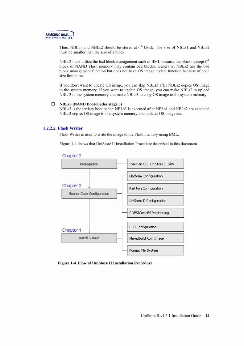
1.2.2.2. Flash Writer Flash Writer is used to write the image to the Flash memory using BML. Figure 1-4 shows that UniStore II Installation Procedure described in this document.
Figure 1-4. Flow of UniStore II Installation Procedure
UniStore II v1.5.1 Installation Guide 15
2. System Environments This chapter describes the system requirements, the directory structure, and Prerequisites to install UniStore II.
2.1. System Requirements To install UniStore II v1.5.1, the following system requirements must be met. Table 2-1 shows the system requirements to install UniStore II on Symbian OS and use it.
Table 2-1. System Requirements
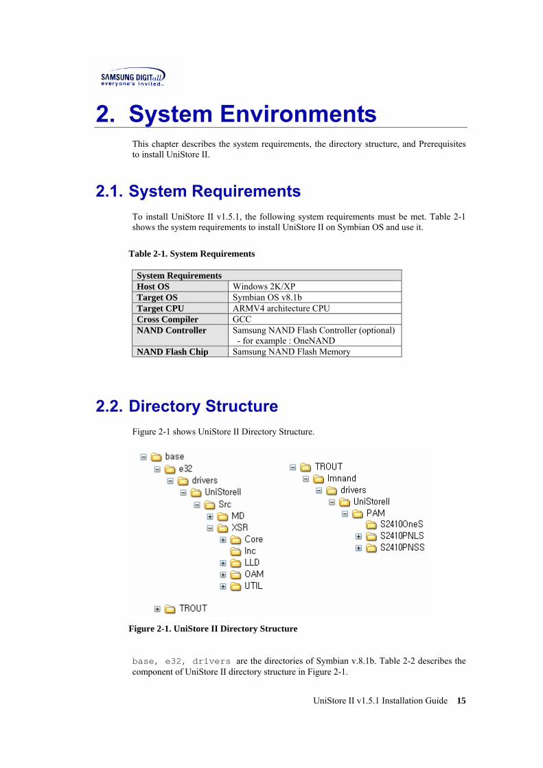
2.2. Directory Structure Figure 2-1 shows UniStore II Directory Structure.
Figure 2-1. UniStore II Directory Structure
base, e32, drivers are the directories of Symbian v.8.1b. Table 2-2 describes the component of UniStore II directory structure in Figure 2-1.
System Requirements Host OS Windows 2K/XP Target OS Symbian OS v8.1b Target CPU ARMV4 architecture CPU Cross Compiler GCC NAND Controller Samsung NAND Flash Controller (optional)
- for example : OneNAND NAND Flash Chip Samsung NAND Flash Memory
UniStore II v1.5.1 Installation Guide 16
Table 2-2. UniStore II Directory Structure
Directory Description Base This directory is a base directory of Symbian OS
v8.1b. e32 This directory has the kernel of Symbian OS v8.1n. drivers This directory has the device driver of Symbian OS
v8.1b. UniStoreII This directory is UniStore II base directory when
UniStore II is installed. Doc This directory has UniStore II related documents. Src This directory has the source code UniStore II. MD This directory has the source code of NAND
Media Driver Interface XSR This directory has the sources code and header
files of XSR layers. Core This directory has XSR core source code. LLD This directory has LLD source code. OAM This directory has OAM source code.
PAM This directory has PAM source code.
INC This directory has the header files of XSR. TROUT This directory is a directory of variant. Lmnand This directory has variant dependent UniStoreII
code includeing UniStoreII media driver mmp file. Drivers This directory has variant dependent device driver
codes. UniStoreII This directory has variant dependent UniStore II
code. PAM This directory has platform depent code in
UniStoreII.
2.3. Prerequisites To install UniStore II on Symbian OS, the following prerequisite must be met. ► Install Symbian OS
1) Install Symbian OS v8.1b on your computer. ☞ Remark For more information about installing Symbian OS v8.1b, refer to Installation part in “Porting Part of Symbian OS v8.1b manual” provided by Symbian.
2) Check BSP operation for the target. ☞ Remark

UniStore II v1.5.1 Installation Guide 17
BSP (Board Support Package) is also called as a base port which Symbian OS operates on the other hardware platform ► Extract UniStoreII_v1.5.1.zip
1) Make a new directory UniStoreII in $base\e32\drivers. ☞ Remark e32 is a directory that the kernel of Symbian OS v8.1b exists in. drivers is that the device driver of Symbian OS v8.1b exists in.
2) Download the provided UniStore II file UniStoreII_v1.5.1.zip, and unzip it in $base\e32\drivers\UniStoreII. Then, you can see the following directory and file structure.
Figure 2-2. UniStore II Directory Structure
UniStore II v1.5.1 Installation Guide 18
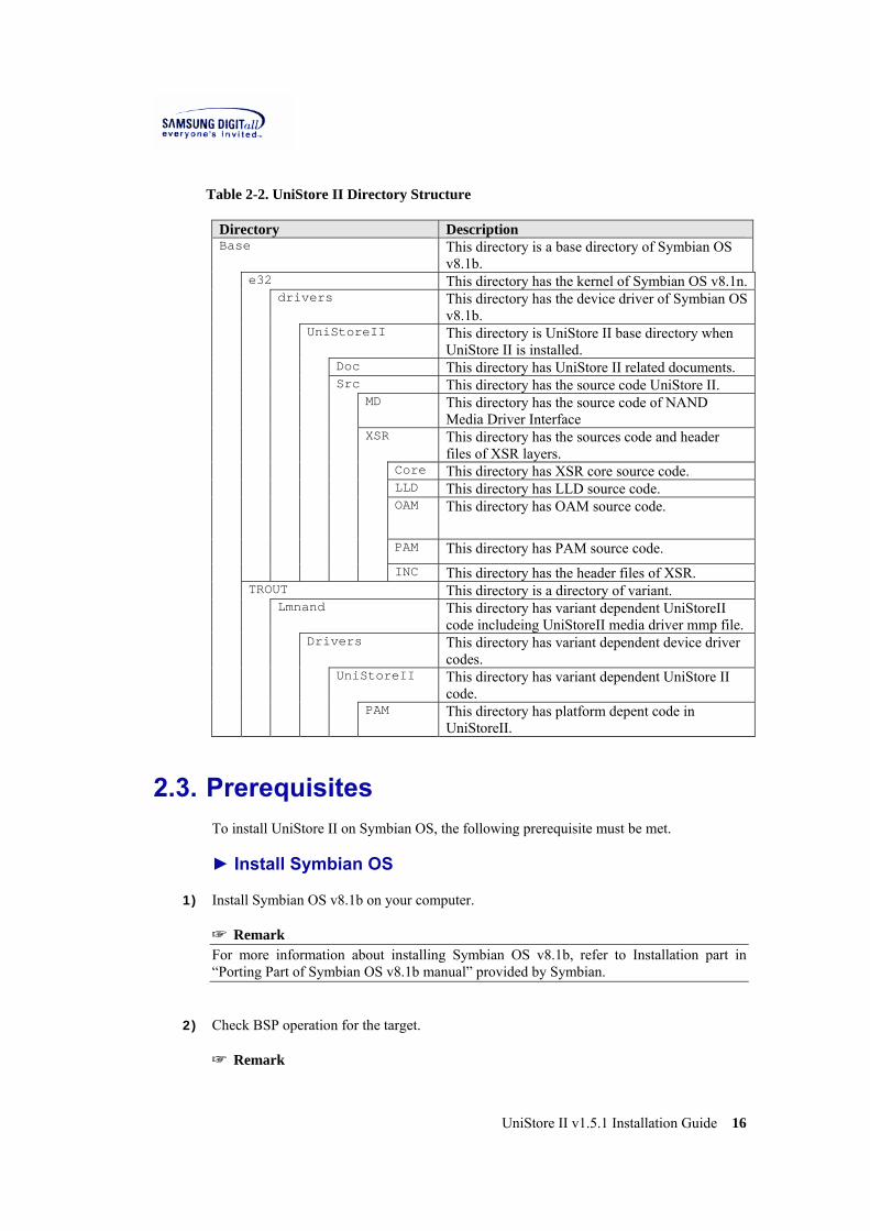
Figure 2-3. UniStore II Directory Structure
3) Dowload the released estart.cpp and overwrite estart.cpp in $base\f32\estart
☞ Remark f32 is a subdirectory of base directory. estart is a direcoty where platform dependent codes are placed..

UniStore II v1.5.1 Installation Guide 19
3. Source Code Configurations This chapter describes the configuration options corresponding to the system environment. It also explains partitioning and building corresponding to the partition. ☞ Note MEDUSII is UniStore II NAND Media Driver.
3.1. Configuration Options
3.1.1. Platform Configuration UniStore II supports two volumes and eight devices at maximum; four devices per a volume. The address of the devices on the platform that is composed of volumes and devices is defined at PAM.cpp. When you want to port UniStore II to other platform, set the platform configuration as follows. (For more detailed information, see XSR porting guide)
The following is a part of PAM.cpp in $base\VARIANT\lmnand\drivers \UniStoreII\PAM\DEVICE ☞ Remark DEVICE is a directory that contains device dependent PAM code. Current PAM directory includes DEVICE directories such as IntapPNLS, IntapPNSS, S2410OneS, S2410PNLS, S2410PNSS and Template. Depending on your configuration, one of them will be integrated with device driver.
#include <XsrTypes.h> #include <PAM.h> #include <OAM.h> #include <LLD.h> #define VOL0 0 #define VOL1 1 #define DEV0 0 #define DEV1 1 #define DEV2 2 #define DEV3 3 VOID* PAM_GetPAParm(VOID) { gstParm[VOL0].nBaseAddr[DEV0] = 0x20000000; gstParm[VOL0].nBaseAddr[DEV1] = NOT_MAPPED; gstParm[VOL0].nBaseAddr[DEV2] = NOT_MAPPED; gstParm[VOL0].nBaseAddr[DEV3] = NOT_MAPPED;
gstParm[VOL0].nEccPol = SW_ECC; gstParm[VOL0].nLSchemePol = SW_LOCK_SCHEME; gstParm[VOL0].bByteAlign = TRUE32; gstParm[VOL0].nDevsInVol = 1; gstParm[VOL0].pExInfo = NULL;

UniStore II v1.5.1 Installation Guide 20
gstParm[VOL1].nBaseAddr[DEV0] = NOT_MAPPED; gstParm[VOL1].nBaseAddr[DEV1] = NOT_MAPPED; gstParm[VOL1].nBaseAddr[DEV2] = NOT_MAPPED; gstParm[VOL1].nBaseAddr[DEV3] = NOT_MAPPED; gstParm[VOL1].nEccPol = HW_ECC; gstParm[VOL1].nLSchemePol = SW_LOCK_SCHEME; gstParm[VOL1].bByteAlign = TRUE32; gstParm[VOL1].nDevsInVol = 0; gstParm[VOL1].pExInfo = NULL; return (VOID *) gstParm; }
Code 3-1. Platform Configuration
The function PAM_GetPAParm is called by BML and LLD. It provides the information of volumes and devices in platform. nBaseAddr is a base address of NAND device for LLD. nEccPol specifies ECC policy. nEccPol should be set to one of NO_ECC, SW_ECC and HW_ECC depending on your system’s ECC policy. There is strict restriction concerned with ECC policy as follows.
Table 3-1. ECC Policy Restriction
nEccPol Restriction NO_ECC If the system does not use any ECC algorithm in terms of HW
or in terms of SW, you must set to NO_ECC. If ECC algorithm on the system is not compatible with SAMSUNG provided ECC algorithm, you must set to NO_ECC. If stored ECC pattern is not compatible with SAMSUNG standard, you must set to NO_ECC. If spare assignment for ECC code is different from Samsung standard, you must set to NO_ECC.
HW_ECC If following three conditions meet, you can set to HW_ECC - ECC is handled by H/W - ECC generation method is compatible with SAMSUNG
provided ECC algorithm. - Stored ECC pattern is compatible with SAMSUNG statndard. - Spare assignment for ECC code is compatible with
Samsung standard. Otherwise, you can not set to HW_ECC.
SW_ECC If you wan to use UniStoreII provided SW_ECC function, you should set to SW_ECC.
For more detailed information, refer to 7.6 section of “XSR Porting Guide”. nLSchemePol is a policy related to write/erase protection; nLSchemePol can be HW_LOCK_SCHEME, SW_LOCK_SCHEME, and NO_LOCK_SCHEME. You can type HW_LOCK_SCHEME in nLSchemePol if NAND device does provide the lock scheme.

UniStore II v1.5.1 Installation Guide 21
You type NO_LOCK_SCHEME in nLSchemePol if NAND device does not use the lock scheme. If you type SW_LOCK_SCHEME in nLSchemePol in order to use the S/W lock scheme, BML will be responsible for the write/erase protection. bByteAlign is used to decide whether BML force the byte alignment or not, when BML gets not-aligned buffer from the upper layer in read/write operation. If you set it as TRUE32, that means that BML layer forces the byte alignment. Otherwise, BML does not care about byte alignment. In this case, byte alignment issue is deferred to LLD. nDevInVol is the number of the allocated devices in the volume. pExInfo is entry for extension usage. It is available for developers who want to add their own platform dependent information.
For more information about PAM_GetPAParm, refer to PAM API part in “XSR Porting Guide”.
3.1.2. MMP Configuration A .mmp project definition file specifies the properties of a project in a platform and it’s independent of platform. The makmake tool converts project definition files into makefiles for particular platforms. The abld tool wraps calls to makmake. It is more convenient to use than makmake directly. You can set mmp configuration through medusii.mmp provided by UniStore II. Code 3-2 shows a part of medusii.mmp in $base\VARIANT\lmnand. // Select OS type ( EKA1 or EKA2 : exclusive ) //macro SYMOS_OAM_EKA1 macro SYMOS_OAM_EKA2 // Select Operation mode (sync or async : exclusive) //macro SYNC_MODE macro ASYNC_MODE // En-/Dis-able Debug message of MD, STL, BML //macro MED_DEBUG //macro STL_DEBUG //macro BML_DEBUG //macro LLD_DEBUG macro OAM_DBGMSG_ENABLE //macro CHECK_WEARCOUNT #define LLD_ONLD #undef LLD_DNANDL #undef LLD_DNANDS #undef LLD_S3C2410 #if defined(LLD_ONLD) SOURCEPATH USIILOC(XSR\LLD\ONLD512) SOURCE ONLD.cpp SYSTEMINCLUDE USIILOC(XSR\LLD\ONLD512) PAMLOC(OneS) SOURCEPATH PAMLOC(OneS) SOURCE PAM.cpp

UniStore II v1.5.1 Installation Guide 22
Code 3-2. mmp Configuration
This following describes that user’s configuration parts in medusii.mmp.
SYMOS_EKA1 / SYMOS_EKA2 This set current OS type. There are two types of kernel in SymbianOS. One is EKA1 whose kernel is not preemptive. The other one is EKA2 whose kernel is preemptive. You must activate only one of them exclusively. ■ Execute UniStoreII in EKA1 macro SYMOS_EKA1 // macro SYMOS_EKA2 ■ Execute UniStoreII in EKA2 // macro SYMOS_EKA1 macro SYMOS_EKA2 Depending on the above, different interrupt APIs of OS is called in PAM.cpp. Currently, SYMOS_EKA2 is set by default.
SYNC_MODE / ASYNC_MODE This specifies Write Operation mode. In synchronous mode, NAND Media Driver completes the write operation request from File System, and returns it. In asynchronous mode, NAND Media Driver handles the write operation request from File System, and stops the request when the predefined number of BML level operations are processed on NAND flash. Then, NAND Media Driver returns the uncompleted request. When the interrupt is occurred, NAND Media Driver redos the uncompleted write operation using ISR and DFC. ■ Execute Synchronous Write Operation macro SYNC_MODE // macro ASYNC_MODE ■ Execute Asynchronous Write Operation //macro SYNC_MODE macro ASYNC_MODE You must choose one between Synchronous Write Operation and Asynchronous Write Operation. If you choose Asynchronous Write Operation, you must the additional settings for Asynchronous Write Operation referring to Synchronous Write Operation and Asynchronous Write Operation part of “XSR Porting Guide”.
UniStore II v1.5.1 Installation Guide 23
Currently, asynchronous Write Operation is set by default.
MED_DEBUG / STL_DEBUG / BML_DEBUG / LLD_DEBUG This sets whether to show the debug message of the layers and modules. To print the debug message, activate XXX_DEBUG macro. ■ Print debug message macro XXX_DEBUG ■ NOT Print debug message //macro XXX_DEBUG You can multiply enable to print debug message. If ROM image is in debug mode, the debug message is printed. If ROM image is in release mode, the debug message is not printed even though the debug is enabled. You can set to show the debug messages of XSR layers and modules. Currently, Media Driver (MED), STL, BML and LLD are set to disable the debug messages. ■ Current Setting //macro MED_DEBUG //macro STL_DEBUG //macro BML_DEBUG //macro LLD_DEBUG
CHECK_WEARCOUNT This sets whether to check Wearcount of the total block in Media Driver. Wearcount in a block is the number of the previous erase operations. If you set to check wearcount, XSR displays the erase count of the whole blocks in open time, and checks that the data to subtrace from max to min is in the boundary (the default boundary is 1000). ■ Check Wearcount macro CHECK_WEARCOUNT ■ NOT Check Wearcount // macro CHECK_WEARCOUNT Currently, checking Wearcount is not set.
LLD_ONENAND / LLD_DNANDL This sets LLD of NAND Media Driver. #undef LLD_EAGLE #define LLD_ONLD #undef LLD_DNANDL #undef LLD_DNANDS

UniStore II v1.5.1 Installation Guide 24
#undef LLD_S3C2410 Type #define in front of the type of device to use a certain NAND device and type #undef in front of other types not to use. Depending on the choice here, what type of LLD is compiled is determined. Currently, OneNAND is set by default. #define LLD_ONLD ☞ Remark Symbian OS defines CPU name to be used in Symbian Company. For example, StrongArm based reference platform is defined as MISA, OMAP as MHELEN, etc. For more information about the platform name, refer to Device Driver part in “Porting Part of Symbian OS v8.1b manual” provided by Symbian.
3.1.3. NAND Physical Partition Configuration UniStore II manages NAND bootloader, OS Image, ROFS (Read-Only File System), and several FATFS (FAT File System) in NAND device. NAND partition means the area where the different data is separately stored such as OS Image, ROFS and FATFS. A maximum number of FATFS partition is 31. Each platform can contain different NAND partitions in a NAND device. You can force NAND partition configuration of platform to the NAND device througn BML_Format. Second parameter for BML_Format contains partition configuration. Figure 3-1 shows an example of NAND partition configuration. You can allocate NAND partition except Reservoir in total NAND device area.
Figure 3-1. Example of NAND Partition Configuration
Reservoir is an area which is composed of blocks reserved for replacing bad blocks. Three blocks to manage Reservoir and N reserved blocks to replace bad blocks are allocated. For the information about the number of reserved blocks N, refer to “Samsung NAND Flash memory & SmartMedia Data Book”. #include <XSRTypes.h> #include <BML.h> #define NUM_OF_VOLS 2 #define VOL0 0 #define VOL1 1 BOOL32 Example(VOID) {
UniStore II v1.5.1 Installation Guide 25
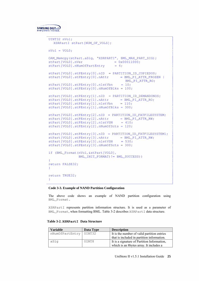
UINT32 nVol; XSRPartI stPart[NUM_OF_VOLS]; nVol = VOL0; OAM_Memcpy(stPart.aSig, “XSRPARTI”, BML_MAX_PART_SIG); stPart[VOL0].nVer = 0x00011000; stPart[VOL0].nNumOfPartEntry = 4; stPart[VOL0].stPEntry[0].nID = PARTITION_ID_COPIEDOS; stPart[VOL0].stPEntry[0].nAttr = BML_PI_ATTR_FROZEN | BML_PI_ATTR_RO; stPart[VOL0].stPEntry[0].n1stVbn = 10; stPart[VOL0].stPEntry[0].nNumOfBlks = 100; stPart[VOL0].stPEntry[1].nID = PARTITION_ID_DEMANDONOS; stPart[VOL0].stPEntry[1].nAttr = BML_PI_ATTR_RO; stPart[VOL0].stPEntry[1].n1stVbn = 110; stPart[VOL0].stPEntry[1].nNumOfBlks = 300; stPart[VOL0].stPEntry[2].nID = PARTITION_ID_FATFILESYSTEM; stPart[VOL0].stPEntry[2].nAttr = BML_PI_ATTR_RW; stPart[VOL0].stPEntry[2].n1stVSN = 410; stPart[VOL0].stPEntry[2].nNumOfScts = 120; stPart[VOL0].stPEntry[3].nID = PARTITION_ID_FATFILESYSTEM1; stPart[VOL0].stPEntry[3].nAttr = BML_PI_ATTR_RW; stPart[VOL0].stPEntry[3].n1stVSN = 530; stPart[VOL0].stPEntry[3].nNumOfScts = 300; if (BML_Format(nVol,&stPart[VOL0],
BML_INIT_FORMAT)!= BML_SUCCESS)) { return FALSE32; } return TRUE32; }
Code 3-3. Example of NAND Partition Configuration
The above code shows an example of NAND partition configuration using BML_Format. XSRPartI represents partition information structure. It is used as a parameter of BML_Format, when formatting BML. Table 3-2 describes XSRPartI data structure.
Table 3-2. XSRPartI Data Structure
Variable Data Type Description nNumOfPartEntry UINT32 It is the number of valid partition entries
that is included in partition information. aSig UINT8 It is a signature of Partition Information,
which is an 8bytes array. It includes a

UniStore II v1.5.1 Installation Guide 26
'XSRPARTI' string. nVer UINT32 It is a version of Partition Information,
which is 0x00011000 at present. stPEntry XSRPartEntry This structure contains independent
Partition information. Currently up to 31 Partition Entries can be stored.
Table 3-3 describes XSRPartEntry data structure.
Table 3-3. XSRPartEntry Data Structure
Variable Data Type Description nID UINT32 It is ID number of the partition nAttr UINT32 It is attribute of the partition. n1stVbn UINT32 It is the first virtual block number of the partition. nNumOfBlks UINT32 It is the number of blocks in the partition. If the
NAND device supports multi-block erase feature, number of blocks in the partition should be larger than 18.
Table 3-4 describes Pre-defined Partittion ID. You can use Pre-defined Partition ID. However, you can newly define Partition ID and use it.
Table 3-4. Pre-defined Partition ID
Partition ID Value Description PARTITION_ID_NBL1 0 NAND bootloader stage 1 PARTITION_ID_NBL2 1 NAND bootloader stage 2 PARTITION_ID_NBL3 2 NAND bootloader stage 3 PARTITION_ID_COPIEDOS
3 OS image copied from NAND flash memory to RAM
PARTITION_ID_DEMANDONOS
4 OS image that is loaded on demand
PARTITION_ID_FATFILESYSTEM
8 FAT file system #0
PARTITION_ID_FATFILESYSTEM1
9 FAT file system #1
PARTITION_ID_FATFILESYSTEM2
10 FAT file system #2
PARTITION_ID_FATFILESYSTEM3
11 FAT file system #3
PARTITION_ID_FATFILESYSTEM4
12 FAT file system #4
PARTITION_ID_FATFILESYSTEM5
13 FAT file system #5
PARTITION_ID_FATFILESYSTEM6
14 FAT file system #6
PARTITION_ID_FATFILESYSTEM7
15
FAT file system #7
PARTITION_ID_FATFILESYSTEM8
16 FAT file system #8
PARTITION_ID_FATFIL 17 FAT file system #9

UniStore II v1.5.1 Installation Guide 27
ESYSTEM9
PARTITION_USER_DEF_BASE
0x10000000 The base value of ID that you can define. You can define Partition Entry ID from 0x10000000 to 0xFFFFFFFF that is reserved in BML. Among Partition ID, from 0 to 0x0FFFFFFF is pre-defined by XSR.
Table 3-5 describes nAttr variable in XSRPartEntry data structure.
Table 3-5. nAttr of XSRPartEntry Data Structure
Attribute Description BML_PI_ATTR_FROZEN | BML_PI_ATTR_RO
It is a read-only attribute for a partition that is not updated in run-time. This can be applied to a boot loader or an OS that will not be updated.
BML_PI_ATTR_RO It is read-only attribute for a partition that can be updated in run-time. It can be changed to a BML_PI_ATTR_RW in run-time by using a BML_IOCtl. It can be applied to an OS or font.
BML_PI_ATTR_RW It is a read-write attribute for a partition that is both readable and writable in run-time. It can be applied to File System.
NAND partition configuration is defined at d_mednand.cpp where BML_Format can be called. To apply NAND partition configuration defined at d_mednand.cpp, you should activate DO_BMLFORMAT macro in mmp file.
3.1.4. STL Configuration The file system type and block size should be specified in format hard disk. STL has to configure a few related items in formatting. After BML format, all RW partitions should be formatted using STL_Format. The following describes the configuration of the member variables of STLConfig structure.
nFillFactor STL stores both user data and meta data on NAND flash memory. meta data area is reserved for the performance improvement and you actually use the rest for the user data area. The user data area can be configured by nFillFactor. For example, nFillFactor value is 100. It allows you to use the whole user data area except meta data area. If nFillFactor is 50, it allows you to use 50 percent of the user data area. As the usable data area becomes smaller, the performance is more improved.
nSnapshots STL meta data includes Snapshot. Snapshot means the latest SAM table. If the number of SAM snapshots in STLConfig is NUM_OF_SNAPSHOT_4, there will be more EUH in one unit for additional SAM snapshots. Additional SAM snapshots are used to reduce time to construct SAM table. It value is 1 or 4(exclusive) If you need more information, refer to detailed design document.

UniStore II v1.5.1 Installation Guide 28
nBlksPerUnit A unit is a logical quantity which can be composed of one block or multiple blocks. Normally, a unit is composed of N blocks and the smallest erasable unit. The number of blocks per unit is configured by nBlksPerUnit. For large block NAND device, nBlksPerUnit should be only 1. And for small block NAND device, nBlksPerUnit can be specified among 1 to 7. As the unit value is increased, the memory used by XSR is larger, but the performance of random write operation becomes better.
nNumOfRsvUnits STL manages the whole memory space as a set of units. Some of units which are called as reserved units and the reserved units are not acessiable by users. The number of the reserved units is configurable and should be more than 2 at least. As the reserved unit value is increased, the usable disk capacity for user will be decreased, but the whole write operation will be improved. Shows an example of configuration using STL_Format. To use RW partition, partition should be opened using STL_Open. The following describes a member variable configuration of STLInfo structure. User can configure nSamBufFactor and bASyncMode when STL_Open is called.
nSamBufFactor STL reads the sector mapping information from NAND flash memory and builds the sector mapping table on RAM to access fast to the sectors. User can set the RAM buffer size for locating the sector mapping table with this nSamsBufFactor. nSamBufFactor indicates the total size of sector mapping table as a percentage and can be 0 to 100. For example, if you try to locate the 50 percent of the sector mapping tables on RAM, you can set the nSamBufFactor as 50. But note that you can set it as 0 or 100 if you try to locate the total sector mapping tables on RAM. In order that STL accesses a sector, sector mapping table of unit should be constructed first. If the sector mapping table is not built on RAM, a buffer is allocated based on LRU replacement algorithm. Then meta information of unit that STL has to access is retrieved from NAND flash memory, and the meta information composes sector mapping tables on the allocated buffer. As the RAM buffer size for locating the sector mapping tables is smaller, access time to a sector is longer, because there is higher probability that the sector mapping table should be newly composed. Consequently, it is better to make the RAM-resident sector mapping tables as many as possible for improved performance, despite of its memory overhead. And you should use the fixed nSamBufFactor value every time STL is opened.
bASyncMode This flag specifies how to manipulate XSR operations. If bASyncMode is set to TRUE, the XSR operations are to be processed asynchronously. Otherwise, the operations are to be processed synchronously. You can set configuration for STLInfo in d_mednand.cpp. Code 3-4 is a part of d_mednand.cpp in $base\e32\drivers\UniStoreII\src\MD. In multiple FATFS partition environments, each partition can have its own configuration. However, value of nBlksPerUnit and bAsyncMode should be identical for each partition in the same volume. If the partition which has a different value for

UniStore II v1.5.1 Installation Guide 29
nBlksPerUnit or bAsyncMode with other partitions in the same volume exists, STL returns error. #include <XSRTypes.h> #include <STL.h> #include <BML.h> #define VOL0 0 #define VOL1 1 #define NUM_OF_FATFS 2 #define FATFS0 0 #define FATFS1 1 #define RESET_ECNT 0 BOOL32 Example(VOID) {
STLConfig stSTLConfig[NUM_OF_FATFS]; UINT32 nVol; nVol = VOL0; stSTLConfig[FATFS0].nFillFactor = 100;
stSTLConfig[FATFS0].nSnapshot = 4 stSTLConfig[FATFS0].nNumOfRsvUnits = 15; stSTLConfig[FATFS0].nBlksPerUnit = 1; stSTLConfig[FATFS1].nFillFactor = 90;
stSTLConfig[FATFS1].nSnapshot = 1; stSTLConfig[FATFS1].nNumOfRsvUnits = 10; stSTLConfig[FATFS1].nBlksPerUnit = 1; if (STL_Format(nVol,
PARTITION_ID_FATFILESYSTEM, &stSTLConfig[FATFS0], RESET_ECNT) != STL_SUCCESS)
{ return FALSE32;
} if (STL_Format(nVol,
PARTITION_ID_FATFILESYSTEM1, &stSTLConfig[FATFS1], RESET_ECNT) != STL_SUCCESS)
{ return FALSE32;
} return TRUE32;
}
Code 3-4. Example of STL Format configuration for multiple FATFS partition environments

UniStore II v1.5.1 Installation Guide 30
for(nCnt = 0; nCnt < NUM_OF_MD_PARTITION; nCnt++) { #ifdef SYNC_MODE astSTLinfo[nCnt].bASyncMode = FALSE32; #else astSTLinfo[nCnt].bASyncMode = TRUE32; #endif astSTLinfo[nCnt].nSamBufFactor = 100; }
Code 3-5. Example of STL Open configuration for multiple FATFS partition environments
3.1.5. Drive Configuration ► Set Drive
1) Open variantmediadef.h file in $base\VARIANT\inc NAND_DRIVECOUNT specifies the number of local drive objects to be assigned to the media driver. Drives that support more than one partition must specify a number greater than 1. For NAND_DRIVELIST, 0 signifies Drive C, 1 signifies drive D and etc. Current configuration sets 3 drives as I, J, k, by default. NAND_NUMMEDIA specifies the total number of DMedia objects to be associated with the media driver. NAND_DRIVENAME is the name of the media driver, for example “Nand”. For more detailed information, refer to Symbian help for drive information. // Parameters for mednand.pdd #define NAND_DRIVECOUNT 3 #define NAND_DRIVELIST 6,7,8 #define NAND_NUMMEDIA 1 #define NAND_DRIVENAME "Nand"
Code 3-6. variantmediadef.h
Note that the number of elements in NAND_DRIVELIST must be the same as the value specified by NAND_DRIVECOUNT.
3.2. OS Partitioning Generally, NAND Media Driver can use three kinds of partitions; FAT partition, ROFS partition, and CompFS partition. This chapter explains the method of the target building when you port UniStore II to target system environment using FAT partition, ROFS partition or CompFS partition.

UniStore II v1.5.1 Installation Guide 31
3.2.1. FAT Partition To use FAT partition, build UniStore II to the target as follows. ► Add FAT Partition to Media Driver
1) Open d_mednand.h in $base\e32 \drivers\UniStoreII\Src\MD.
Modify a NUM_OF_MD_PARTITION as number of FAT Partitions which you want to use.
/**********************************************************/ /* Configuration value for MD */ /**********************************************************/ #define NUM_OF_MD_PARTITION 2
When you finish modifying d_mednand.h, save the file and close it.
2) Open d_mednand.cpp in $base\e32 \drivers\UniStoreII\Src\MD.
Add FAT Partition IDs. The number of FAT Partition is set from step 1.
/**********************************************************/ /* Local Variable for MD */ /**********************************************************/ static TUint aMDPartID[NUM_OF_MD_PARTITION] =
{PARTITION_ID_FILESYSTEM, PARTITION_ID_FILESYSTEM1}; When you finish modifying d_mednand.cpp, save the file and close it.
3.2.2. ROFS Partition To use ROFS partition, build UniStore II to the target as follows. ► Build ROFS filesystem
1) Go to $base\f32\group > bldmake bldfiles > abld build arm4 erofs ► Create ROFS Image
1) Open an editor, write as follows, and save it as *.oby. It shows an example to write a file test.oby. rofsname = test.rofs rofssize = 0x80000 version = 0.01(1000) file = bin\TechView\epoc32\release\arm4\urel\t_ramstr.exe \test\t_rofs_ramstr.exe file = bin\TechView\epoc32\release\arm4\urel\t_fsysbm.exe \test\t_rofs_fsysbm.exe

UniStore II v1.5.1 Installation Guide 32
2) Save the file in $base\e32\rombuild when you finish writing test.oby and close it
3) Go to $base\e32\rombuild in command prompt, Type the following command, and press an enter key. Then, the image file test.rofs is created. > rofsbuild test.oby ► Write ROFS Image to NAND Flash Memory
1) Unlock NAND device using BML_IOCTL_UNLOCK_WHOLEAREA, IOCtl Code of BML.
2) Erase NAND partition that ROFS image would be written using BML_EraseBlk.
3) Write ROFS image to NAND partition using BML_Write. ► Add ROFS Partition to File Server To add ROFS partition to File Server, modify header.iby and estart.cpp as follows.
1) To use ROFS and not to use CompFS, write the following in header.iby. #define WITH_ROFS #undef WITH_COMP When you finish modifying header.iby, save the file and close it.
2) Open estart.cpp in $base\f32\estart\estart.cpp.
3) To use ROFS and not to use CompFS, verify the following in estart.cpp. TBool gMountRofs = ETrue; If gMountRofs is EFalse, modify it into ETrue.
4) To apply the modified configuration part, go to $base\f32\group\ in command prompt and Type the following command and press an enter key. Then, the modified
configuration part is applied to the system. ( Since estart file is already replaced with released one, you should rebuild estart even if you does nothing in step 4.) > bldmake bldfiles
5) You should build a new image of the modified configuration part. Type the following command and press an enter key. > abld build ASSP estart Currently, ASSP (Application Specific Standard Product) can be ARMI or ARM4.
UniStore II v1.5.1 Installation Guide 33
After building the image, e32start.exe is created in $epoc32\release\ASSP\ UDEB[UREL].
3.2.3. CompFS Partition CompFS partition combines several ROFS amd ROMFS into one. It combines one ROFS partition with existing ROMFS partition to look like Z drive. Z drive in Symbian OS is the system drive. To use CompFS partition, build the nexessary unages as follows. ► Build ROFS filesystem
1) Go to $base\f32\group > bldmake bldfiles > abld target arm4 erofs ► Create ROFS Image
1) Open an editor, write as follows, and save it as *.oby. It shows an example to write a file test.oby. rofsname = test.rofs rofssize = 0x80000 version = 0.01(1000) file = bin\TechView\epoc32\release\arm4\urel\t_ramstr.exe \test\t_rofs_ramstr.exe file = bin\TechView\epoc32\release\arm4\urel\t_fsysbm.exe \test \t_rofs_fsysbm.exe
2) Save the file in $base\e32\rombuild when you finish writing test.oby and close it.
3) Go to $base\e32\rombuild in command prompt, Type the following command, and press an enter key. Then, the image file test.rofs is created. > rofsbuild test.oby ► Write CompFS Image to NAND Flash Memory
1) Unlock NAND device using BML_IOCTL_UNLOCK_WHOLEAREA, IOCtl Code of BML.
2) Erase NAND partition that CompFS image would be written using BML_EraseBlk.
3) Write CompFS image to NAND partition using BML_Write.
UniStore II v1.5.1 Installation Guide 34
► Add CompFS Partition to File Server To add CompFS partition to File Server, modify header.iby.
1) To use CompFS and not to use ROFS, write the following in header.iby. #undef WITH_ROFS #define WITH_COMP When you finish modifying header.iby, save the file and close it.
2) Go to $base\f32\group\ in command prompt, Type the following command and press an enter key, Then, the modified configuration part is applied to the system. > bldmake bldfiles
3) You should build a new image of the modified configuration part. Type the following command and press an enter key. > abld build ASSP estart Currently, ASSP(Application Specific Standard Product) can be ARMI or ARM4. After building the image, e32start.exe is created in $epoc\release\ASSP\ UDEB[UREL].

UniStore II v1.5.1 Installation Guide 35
4. Installation & Build This chapter first explains how to install UniStore II on Symbian OS, and build it and describes how to check that the installation is properly completed. ☞ Note MEDUSII is UniStore II NAND Media Driver.
4.1. Build ROM Image ► Build VARIANT
1) Go to $base/VARIANT > bldmake bldfiles > abld build ASSP ► Build NAND Media Driver
1) Open bld.inf in $base\variant\lmnand . Bld.inf is a component description file, and defines the platform port. PRJ_PLATFORMS ARM4 ARMV4 ARM4T ARMV5 PRJ_EXPORTS rom\lmnand.iby \epoc32\rom\include\ rom\lmnand.oby \epoc32\rom\include\ rom\kernel.iby \epoc32\rom\lmnand\ PRJ_MMPFILES medusii
2) Open the lm.mmh in the same directory and modify the path of source code.
#define LmTarget(name,ext) _lmnand_##name##.##ext #define USIILOC(component)
..\..\e32\drivers\UniStoreII\Src\##component #define PAMLOC(pamtype)
.\Drivers\UniStoreII\PAM\S2410##pamtype
Verify the location of source code.
3) Go to $base\variant\lmnand in command prompt, to apply the modified configuration part. Type the following command and press an enter key. Then, the modified configuration part is applied to the system. > bldmakes bldfiles > abld export

UniStore II v1.5.1 Installation Guide 36
> abld makefile > abld library > abld target #ASSP# UDEB[UREL] medusii Now, _lmnand_MEDUSII.PDD is made in $bin\TechView \epoc32\release \KMAIN\UDEB[UREL].
4) Open the kernel.iby file in $base\variant\rom. Add the below statement. extension[VARID]=\epoc32\Release\##KMAIN##\##BUILD##\_lmnand_MEDUSII.PDD \System\Bin\MEDUSII.PDD Above statement specifies that _lmnand_MEDUSII.PDD should be loaded when system booting. ► Build Estart
1) Open estart.cpp in $base\f32\estart\ Since UniStoreII does not use FS extension any more, estart.cpp should be modified. static const SFileSystemInfo FileSystems[] = { #ifndef __EPOC32__ {DetectEmulRAM, _S("efat32"), _S("fat"),
0, FS_FLAG_FORMAT}, {DetectEmul_CF_FAT32,_S("efat32"), _S("fat"),
0, FS_FLAG_FORMAT}, {DetectEmulRAM, _S("efat"), _S("fat"),
0, FS_FLAG_FORMAT}, {DetectEmul_CF_FAT, _S("efat"), _S("fat"),
0, FS_FLAG_FORMAT}, {DetectFtl, _S("efat"), _S("fat"),
0, FS_FLAG_FORMAT_CORRUPT}, #else {DetectELocal, _S("elocal"), _S("fat"), 0, 0}, {DetectFtl, _S("elocal"), _S("fat"),
0, FS_FLAG_FORMAT_CORRUPT}, #endif {DetectRofs, _S("erofs"), _S("rofs"),
0, FS_READONLY}, {DetectEneaLFFS, _S("elffs"), _S("lffs"),
0, FS_FLAG_FORMAT}, {DetectIso9660, _S("iso9660"), 0, 0, 0}, {DetectNtfs, _S("ntfs"), 0, 0, 0}, };
2) Go to $base\f32\group > bldmkae bldfiles > abld export > abld makefile #ASSP# estart > abld target #ASSP# UDEB[UREL] estart check the creation of E32STRT.EXE in $epoch32\release\#ASSP#\UDEB [UREL].

UniStore II v1.5.1 Installation Guide 37
3) Add below statement into f32.iby in $base\f32\rom
file=\Epoc32\Release\##MAIN##\##BUILD##\e32strt.exe
System\Bin\estart.exe
► Build Test program
1) Go to $base\f32test\group in command prompt to make test program. Type the following command and press an enter key. > bldmakes bldfiles > abld test build arm4 t_ramstr > abld test build arm4 t_fsymbm check t_ramstr and t_fsymbm in \epoc32\Release\#ASSP#\#UDEB[UREL]# directory.
2) Open kernel.iby in $base\variant\rom directory. Add below statement data[MAGIC]=\epoc32\Release\##KMAIN##\##BUILD##\t_ramstr.exe
\test\t_ramstr.exe data[MAGIC]=\epoc32\Release\##KMAIN##\##BUILD##\ t_fsysbm.exe \test\ t_fsysbm.exe Above code specifies that t_ramstr.exe and t_fsymbm.exe be loaded on booting time. ► Build ROM Image If you use ROFS or CompFS Partition, go to step 1). If you do not use ROFS or CompFS Partition, go to step 4). For more information about ROFS and CompFS Partition, refer to Chapter 3.2.
1) Open an editor, write as follows, and save it as *.oby. It shows an example to write a file test.oby. rofsname = test.rofs rofssize = 0x80000 version = 0.01(1000) file = bin\TechView\epoc32\release\arm4\urel\t_ramstr.exe \test\t_rofs_ramstr.exe file = bin\TechView\epoc32\release\arm4\urel\t_fsysbm.exe \test\t_rofs_fsysbm.exe
2) Save the file in $base\e32\rombuild when you finish writing test.oby and close it.
3) Go to $base\e32\rombuild in command prompt, Type the following command, and press an enter key. Then, the image file test.rofs is created.

UniStore II v1.5.1 Installation Guide 38
> rofsbuild test.oby
4) Go to $base\e32\rombuild in command prompt to build the modified ROM image and Type the following command and press the enter key. Then, ROM image is built. rom -v trout -t tshell --build=urel Now, troutarm4.img is created in $base\e32\rombuild.
5) Download troutarm4.img to the target and boot it. Then, FAT partition using NAND flash memory is installed I drive. ☞ Remark From step 1) to step 2) are optional. If you use ROFS or CompFS Partition, go to step 1). If you do not use ROFS or CompFS Partition, go to step 4). For more information about ROFS and CompFS Partition, refer to Chapter 3.2.
4.2. Format File System
1) Go to i drive, which UniStore II is installed, in command prompt. Type dir, a command to show the directory of the current position, and press the enter key. Then, the error message is showed as follows. > dir File or directory not found
2) Type format, a command to format a drive, and press the enter key. Then, the drive is formatted as follows. > format i: *****
3) Type chkdsk, a command to check a disk drive, and press the enter key. Then, you can check that the drive has no error as follows. > chkdsk i: Complete - no errors
4) Type dir again and press the enter key. Then, you can check that the device is properly installed, formatted, and worked.

UniStore II v1.5.1 Installation Guide 39
> dir Directory of I:\ 0 Files 0 Directories
UniStore II v1.5.1 Installation Guide 40
Appendix
I. medusii.mmp The following is the whole source code of medusii.mmp; the real target is TROUT, the emulator is WINS, and the operation system is Symbian. The user-changeable parts and their conditions are described in detail in chapter 3.1.2. // MEDUSII.MMP // // MMP for UniStore II // COPYRIGHT 2003-2006, SAMSUNG ELECTRONICS CO., LTD. // OPTION CW -w off #include <..\variant.mmh> #include <lm.mmh> target LmTarget(medusii,pdd) targettype pdd #include "..\..\e32\kernel\kern_ext.mmh" #define SYMBIAN80B // Choose Symbian OS macro SYMOS_OAM macro REAL_TARGET // Select OS type ( EKA1 or EKA2 : exclusive ) //macro SYMOS_OAM_EKA1 macro SYMOS_OAM_EKA2 // Select Operation mode (sync or async : exclusive) //macro SYNC_MODE macro ASYNC_MODE // En-/Dis-able Debug message of MD, STL, BML //macro MED_DEBUG //macro STL_DEBUG //macro BML_DEBUG //macro LLD_DEBUG macro OAM_DBGMSG_ENABLE // Print wearcount of whole blocks in the MediaDriver //macro CHECK_WEARCOUNT #undef LLD_EAGLE #define LLD_ONLD #undef LLD_DNANDL #undef LLD_DNANDS

UniStore II v1.5.1 Installation Guide 41
#undef LLD_S3C2410 SOURCEPATH USIILOC(MD) SOURCE d_mednand.cpp debug.cpp SOURCEPATH USIILOC(XSR\OAM\SymOS) SOURCE SymOSOAM.cpp SOURCEPATH USIILOC(XSR\Core\STL) SOURCE GarbageQueue.cpp OpQueue.cpp SectorMap.cpp
STLInterface.cpp VirtualNand.cpp SamBufMgr.cpp
SOURCEPATH USIILOC(XSR\Core\BML) SOURCE BadBlkMgr.cpp BMLInterface.cpp SwEcc.cpp #if defined(LLD_ONLD) SOURCEPATH USIILOC(XSR\LLD\ONLD) SOURCE ONLD.cpp SYSTEMINCLUDE USIILOC(XSR\LLD\ONLD) PAMLOC(OneS) SOURCEPATH PAMLOC(OneS) SOURCE PAM.cpp #elif defined(LLD_EAGLE) SOURCEPATH USIILOC(XSR\LLD\Eagle) SOURCE EagleWp.cpp eagle16.cpp SYSTEMINCLUDE USIILOC(XSR\LLD\Eagle) USIILOC(XSR\INC)
PAMLOC(EagS) SOURCEPATH PAMLOC(EagS) SOURCE PAM.cpp #elif defined(LLD_S3C2410) SOURCEPATH USIILOC(XSR\LLD\S3C2410) SOURCE S2410Emb.cpp ecc.cpp SYSTEMINCLUDE USIILOC(XSR\LLD\S3C2410) PAMLOC(EmbS) SOURCEPATH PAMLOC(EmbS) SOURCE PAM.cpp #elif defined(LLD_DNANDL) SOURCEPATH USIILOC(XSR\LLD\PNL) SOURCE PNL.cpp SYSTEMINCLUDE USIILOC(XSR\LLD\PNL) PAMLOC(PNLS) SOURCEPATH PAMLOC(PNLS) SOURCE PAM.cpp #elif defined(LLD_DNANDS)

UniStore II v1.5.1 Installation Guide 42
SOURCEPATH USIILOC(XSR\LLD\PNS) SOURCE PNS.cpp SYSTEMINCLUDE USIILOC(XSR\LLD\PNS) PAMLOC(PNSS) SOURCEPATH PAMLOC(PNSS) SOURCE PAM.cpp #elif defined(LLD_SIM_PNS) SOURCEPATH USIILOC(XSR\LLD\PNS) SOURCE PNSsym.cpp SYSTEMINCLUDE USIILOC(XSR\LLD\PNS) PAMLOC(PNSS) SOURCEPATH PAMLOC(PNSS) SOURCE PAM.cpp #elif defined(LLD_SIM_ONLD) SOURCEPATH USIILOC(XSR\LLD\OneNAND) SOURCE ONLDsym.cpp SYSTEMINCLUDE USIILOC(XSR\INC) USIILOC(XSR\LLD\OneNAND) PAMLOC(OneS) SOURCEPATH PAMLOC(OneS) SOURCE PAMsim.cpp #endif SYSTEMINCLUDE USIILOC(XSR\Inc) ..\..\e32\include\drivers ..\..\S3C2440 systeminclude VariantMediaDefIncludePath library ekern.lib elocd.lib euser.lib library VariantTarget(kas3c2440,lib) START WINS WIN32_LIBRARY kernel32.lib END EPOCALLOWDLLDATA UID 0x100039d0 0x101f9bcf capability all Code A-1. medusii.mmp
II. Algorithm of NAND Media Driver Interface File Server of Symbian OS requests data read/write as a unit of bytes. However, XSR can handle data read/write request as a unit of blocks (sectors). Thus, NAND Media Driver Interface transfers bytes-unit data of File Server to blocks-unit data, and delivers the changed data as a unit of blocks to XSR. NAND Media Driver Interface receives information about the buffer from File System, the size of data to handle, the start byte address to read or write data.

UniStore II v1.5.1 Installation Guide 43
The following is examples that Media Driver Interface executes the read/write operation. Each example is categorized into the number of sectors and the read/write operation.
1) Data exists in a sector We suppose 100bytes data is going to be handled, and the data exists in a sector (512bytes) as follows.
Figure A-1. Data exists in a sector
The following describes the steps that Media Driver Interface executes each read and write operation in order. Read Operation
1. File System gives a command Media Driver Interface to execute the read operation.
2. Media Driver Interface finds the start address of data to be read in the sector address of NAND flash memory.
3. Media Driver Interface calculates the start address of data in a sector and the size of data to be read. So, it checks 100bytes data exists in a sector of NAND flash memory.
4. Media Driver Interface reads 512bytes, a whole sector, and copies it to its own buffer.
5. Media Driver Interface copies 100bytes data for the read operation from its own buffer to the system buffer, and return it.
Write Operation
1. File System gives a command Media Driver Interface to execute the write operation.
2. Media Driver Interface finds the start address of data to be written in the sector address of NAND flash memory.
3. Media Driver Interface calculates the start address of data in a sector and the size of data to be written. So it checks 100bytes data exists in a sector of NAND flash memory.
Operation Unit
512 bytes
100 bytes

UniStore II v1.5.1 Installation Guide 44
4. Media Driver Interface reads 512bytes, a whole sector, and copies it to its own buffer.
5. Media Driver Interface updates 100bytes data to be written, copied from the file system, to its own buffer (a buffer that 512bytes data is already copied) at the start address.
6. Media Driver Interface writes a whole buffer, 512bytes data, from its own buffer to NAND flash memory, and returns it.
2) Data exists in more than three sectors We suppose 2000byte data is going to be handled, and the data exists in five sectors (100bytes + 512bytes + 512bytes + 512bytes + 364 bytes) as follows. In handling data that exists in more than three sectors; Media Driver Interface handles a set of contiguous 512bytes at a time. In this example, Media Driver Interface handles 512bytes * 3 sectors at once.
Figure A-2. Data exists in more than three sectors
The following describes the steps that Media Driver Interface executes each read and write operation in order. Read Operation
1. File System gives a command Media Driver Interface to execute the read operation.
2. Media Driver Interface finds the start address of data to be read in the sector address of NAND flash memory.
3. Media Driver Interface calculates the start address of data in a sector and the size of data to be read. So, it checks 2000bytes data exists in five sectors of NAND flash memory as 100bytes + 512bytes + 512bytes + 512bytes + 364bytes.
4. Media Driver Interface reads first 512bytes, a whole sector, and copies it to its own buffer.
5. Media Driver Interface copies 100bytes data for the read operation from its own buffer to the system. Media Driver Interface reads 100bytes data from the start address in a sector to
Operation Unit
512 bytes
Operation Unit
512 bytes x 3
Operation Unit
512 bytes
100 bytes 364 bytes 512 bytes 512 bytes 512 bytes

UniStore II v1.5.1 Installation Guide 45
the end of the sector, and then finds that only 100bytes are read. Media Driver Interface notifies the file system that it read 100bytes data, and returns it.
6. File System again gives a command Media Driver Interface to execute it to its own buffer.
☞ Note In reading or writing data of sector that is full, Media Driver Interface does not copy the sector to its own buffer. Data of one or more contiguous sectors can be read or written as it is; the whole untouched sectors are read or written. Media Driver Interface does nothing, and sends the address of the full-of-data and contiguous sectors (received from the file system) to the lower layer, XSR (especially STL). Then, STL reads or writes data as a set of the sector. If there is no contiguous sectors, Media Driver Interface skips from step 7) to step 9), and go to step 10).
7. Media Driver Interface sends the address of the contiguous sectors to be read, from the second sector to the fourth sector, to the lower layer XSR (especially STL). XSR (especially STL) reads the whole sectors corresponding to the address received from Media Driver Interface.
8. Media Driver Interface notifies the file system that it reads 1536bytes (512bytes * 3) data from the second sector to the fourth sector, and returns it.
9. File System again gives a command Media Driver Interface to execute it to its own buffer.
10. Media Driver Interface reads 512bytes of the fifth sector, a whole sector, and copies it to its own buffer.
11. Media Driver Interface copies 364bytes data (the left data to be read) for the read operation from its own buffer to the system buffer. Media Driver Interface notifies the file system that it reads 364bytes data, so totally 2000bytes, and returns it.
Write Operation
1. File System gives a command Media Driver Interface to execute the write operation.
2. Media Driver Interface finds the start address of data to be written in the sector address of NAND flash memory.
3. Media Driver Interface calculates the start address of data in a sector and the size of data to be written. So, it checks 2000 bytes data exists in five sectors of NAND flash memory as 100bytes + 512bytes + 512bytes + 512bytes + 364 ytes.
4. Media Driver Interface reads first 512bytes, a whole sector, and copies it to its own buffer.

UniStore II v1.5.1 Installation Guide 46
5. Media Driver Interface updates 100bytes data to be written, copied from the file system, to its own buffer (a buffer that 512bytes data is already copied) at the start address.
6. Media Driver Interface writes a whole buffer, 512bytes, from its own buffer to NAND flash memory. Media Driver Interface Writes 100bytes data from the start address in a sector to the end of the sector, and then finds that only 100bytes are written. Media Driver Interface notifies the file system that it writes 100bytes data, and returns it.
7. File System again gives a command Media Driver Interface to execute the write operation.
☞ Note In reading or writing data of sector that is full, Media Driver Interface does not copy the sector to its own buffer. Data of one or more contiguous sectors can be read or written as it is; the whole untouched sectors are read or written. Media Driver Interface does nothing, and sends the address of the full-of-data and contiguous sectors (received from the file system) to the lower layer, XSR (especially, STL). Then, STL reads or writes data as a set of the sector. If there is no contiguous sectors, Media Driver Interface skips from step 8) to step 10), and go to step 11).
8. Media Driver Interface sends the address of contiguous sectors to be written, from the second sector to the fourth sector, to the lower layer XSR (especially STL). XSR (especially STL) reads the whole sectors corresponding to the address received from Media Driver Interface.
9. Media Driver Interface notifies the file system that it writes 1536bytes (512bytes * 3) from the second sector to the fourth sector, and returns it.
10. File System again gives a command Media Driver Interface to execute it to its own buffer.
11. Media Driver Interface reads 512bytes of the fifth sector, a whole sector, and copies to its own buffer.
12. Media Driver Interface updates 364bytes data to be write, copied from the file system, to its own buffer (a buffer that 512bytes data is already copied) at the start of the next sector.
13. Media Drive writes a whole buffer, 512bytes data, from its own buffer to NAND flash memory. Media Driver Interface notifies the file system that is writes 364bytes, so totally 2000bytes, and returns it.
Such as last example, Media Driver Interface can cut the data into three pieces at maximum. In handling data of the whole sectors, Media Driver Interface manages a set of 512bytes contiguous sectors at once. Therefore, although the size of data is huge, data can be cut as three pieces as (X + 512byte * Y + Z).


![Report on Business Plan on UNISTORE, a Retail Superstore [Elegant (VII)]](https://img.dokumen.tips/doc/110x75/55a5aaff1a28abaa068b45e9/report-on-business-plan-on-unistore-a-retail-superstore-elegant-vii.jpg)