Embed Size (px)
Citation preview
UFC 4-022-03 1 October 2013
UNIFIED FACILITIES CRITERIA (UFC)
APPROVED FOR PUBLIC RELEASE; DISTRIBUTION UNLIMITED
SECURITY FENCES AND GATES
Downloaded from http://www.everyspec.com
UFC 4-022-03 1 October 2013
UNIFIED FACILITIES CRITERIA (UFC)
SECURITY FENCES AND GATES
Any copyrighted material included in this UFC is identified at its point of use. Use of the copyrighted material apart from this UFC must have the permission of the copyright holder. U.S. ARMY CORPS OF ENGINEERS NAVAL FACILITIES ENGINEERING COMMAND (Preparing Activity) AIR FORCE CIVIL ENGINEER CENTER Record of Changes (changes are indicated by \1\ ... /1/) Change No. Date Location
This UFC supersedes NAVFAC Military Handbook 1013/10, Design Guidelines for Security Fencing, Gates, Barriers, and Guard Facilities.
Downloaded from http://www.everyspec.com
UFC 4-022-03 1 October 2013
FOREWORD
The Unified Facilities Criteria (UFC) system is prescribed by MIL-STD 3007 and provides planning, design, construction, sustainment, restoration, and modernization criteria, and applies to the Military Departments, the Defense Agencies, and the DoD Field Activities in accordance with USD (AT&L) Memorandum dated 29 May 2002. UFC will be used for all DoD projects and work for other customers where appropriate. All construction outside of the United States is also governed by Status of Forces Agreements (SOFA), Host Nation Funded Construction Agreements (HNFA), and in some instances, Bilateral Infrastructure Agreements (BIA.) Therefore, the acquisition team must ensure compliance with the most stringent of the UFC, the SOFA, the HNFA, and the BIA, as applicable. UFC are living documents and will be periodically reviewed, updated, and made available to users as part of the Services’ responsibility for providing technical criteria for military construction. Headquarters, U.S. Army Corps of Engineers (HQUSACE), Naval Facilities Engineering Command (NAVFAC), and Air Force Civil Engineer Center (AFCEC) are responsible for administration of the UFC system. Defense agencies should contact the preparing service for document interpretation and improvements. Technical content of UFC is the responsibility of the cognizant DoD working group. Recommended changes with supporting rationale should be sent to the respective service proponent office by the following electronic form: Criteria Change Request. The form is also accessible from the Internet sites listed below. UFC are effective upon issuance and are distributed only in electronic media from the following source:
x Whole Building Design Guide web site http://dod.wbdg.org/. Refer to UFC 1-200-01, General Building Requirements, for implementation of new issuances on projects. AUTHORIZED BY:
JAMES C. DALTON, P.E. JOSEPH E. GOTT, P.E. Chief, Engineering and Construction Chief Engineer U.S. Army Corps of Engineers Naval Facilities Engineering Command
JOE SCIABICA, SES MICHAEL McANDREW Director Director, Facilities Investment and Management Air Force Civil Engineer Center Office of the Deputy Under Secretary of Defense
(Installations and Environment)
Downloaded from http://www.everyspec.com
UFC 4-022-03 1 October 2013
Unified Facilities Criteria (UFC) New Document Summary Sheet
Document: UFC 4-022-03, Security Fences and Gates.
Superseding: NAVFAC Military Handbook 1013/10, Design Guidelines for Security Fencing, Gates, Barriers, and Guard Facilities.
Document Description and Need:
Purpose: This document is to provide a unified approach for the design, selection, and installation of security fences and gates. The examples provided in the UFC are for illustration only and must be modified and adapted to satisfy service and installation specific constraints. This document is not intended to address procedural issues such as threat level determination and security operations or to provide specific design criteria such as impact forces. This UFC was developed by consolidating and refining criteria from USACE Protective Design Center, Naval Facilities Engineering Command (NAVFACENGCOM), and available military, government, and commercial sources that are listed in Appendix A of this document. Application and Use: Commanders, security personnel, planners, designers, architects, and engineers must use this UFC when evaluating existing and providing new security fences and gates. Need: Fences and gates are primarily used to define perimeters; however, Department of Defense (DoD) and Service regulations require fencing to be provided for certain protected/restricted areas. DoD and Service policies address certain fencing requirements. This UFC focuses on the requirements for security fences, however, the information and design details presented within may also be used for general or perimeter fencing. Modifications to existing fencing are not required to meet this new UFC.
Impact: The following direct benefits will result:
x This document does not set the requirement for security operations at the installation perimeter.
x No additional cost impacts are anticipated by the publication of this document. x This document does not have any adverse impacts on environmental,
sustainability, or constructability policies or practices.
Unification Issues There are no unification issues.
Downloaded from http://www.everyspec.com
UFC 4-022-03 1 October 2013
i
TABLE OF CONTENTS CHAPTER 1 INTRODUCTION ....................................................................................... 5
1-1 PURPOSE ................................................................................................. 5
1-2 APPLICABILITY ........................................................................................ 5
1-3 SECURITY FENCES AND GATES ........................................................... 5
1-4 SCOPE AND GUIDANCE ......................................................................... 5
1-4.1 Drawings ................................................................................................ 5
1-5 GENERAL BUILDING REQUIREMENTS ................................................. 5
1-5.1 UFC Application ..................................................................................... 6
1-5.2 Requirements Determination ................................................................. 6
1-5.3 Integration With Other Requirements .................................................... 6
1-6 VULNERABILITY AND RISK ASSESSMENT .......................................... 7
1-7 POLICY REQUIREMENTS........................................................................ 8
1-7.1 Department of Defense (DoD) ............................................................... 8
1-7.2 Geographic Combatant Commander (GCC) Requirements .................. 9
1-7.3 Service Requirements ........................................................................... 9
1-7.4 Installation Specific Requirements ....................................................... 11
1-7.5 Airfield Requirements .......................................................................... 11
1-8 PHYSICAL SECURITY ........................................................................... 11
1-8.1 Physical Security System .................................................................... 11
1-9 EMERGENCY ACCESS .......................................................................... 12
1-10 CORROSION PREVENTION CONTROL ................................................ 12
1-10.1 Material Selection and Coatings .......................................................... 12
1-11 REFERENCES ........................................................................................ 13
1-12 GLOSSARY ............................................................................................. 13
CHAPTER 2 FENCING ................................................................................................. 15
2-1 FUNCTION .............................................................................................. 15
2-2 CHAIN LINK FENCING ........................................................................... 15
2-2.1 Chain Link Fencing Fabric ................................................................... 15
2-3 ORNAMENTAL FENCES ........................................................................ 19
2-4 WELDED WIRE MESH FABRIC FENCING ............................................ 19
2-4.1 Fence Components, Fittings, and Accessories .................................... 19
2-5 EXPANDED METAL FENCING .............................................................. 20
Downloaded from http://www.everyspec.com
UFC 4-022-03 1 October 2013
ii
2-5.1 Retrofit Existing Fence ......................................................................... 21
2-5.2 Fence Components, Fittings, and Accessories .................................... 21
2-6 FARM STYLE FENCES .......................................................................... 21
2-7 EXPEDITIONARY PERIMETER FENCING............................................. 21
2-8 FENCE FABRIC HEIGHT........................................................................ 22
2-9 TOP GUARDS ......................................................................................... 22
2-9.1 Outrigger/Barbed Wire Arm Material Specifications ............................. 22
2-9.2 Barbed Wire and Barbed Tape Concertina .......................................... 22
2-10 GROUNDING .......................................................................................... 24
2-11 REINFORCEMENT FOR FENCING ........................................................ 24
2-11.1 Deadman Anchor ................................................................................. 25
2-12 SPECIAL SECURITY FEATURES .......................................................... 26
2-12.1 Clear Zones ......................................................................................... 26
2-12.2 Double Fence Lines ............................................................................. 26
2-12.3 Fence Line Electronic Security Systems .............................................. 29
2-12.4 Security Lighting .................................................................................. 29
2-12.5 Patrol Roads ........................................................................................ 29
2-12.6 Drainage Culverts and Utility Openings ............................................... 30
2-12.7 Drainage Crossing ............................................................................... 33
2-12.8 Tunneling Prevention ........................................................................... 34
CHAPTER 3 GATES .................................................................................................... 39
3-1 GATES OVERVIEW ................................................................................ 39
3-1.1 Access Control..................................................................................... 39
3-2 PERSONNEL GATES ............................................................................. 39
3-2.1 Single Swing Gates ............................................................................. 39
3-2.2 Turnstile (Rotational) Gates ................................................................. 40
3-3 VEHICULAR GATES .............................................................................. 41
3-3.1 Sliding Gates ....................................................................................... 41
3-3.2 Cantilevered Gates .............................................................................. 42
3-3.3 Double Swing Gates ............................................................................ 42
3-3.4 Vertical Pivot Gate ............................................................................... 44
3-3.5 Overhead (Sliding) Gates .................................................................... 44
3-3.6 Vertical Lift Gate .................................................................................. 45
Downloaded from http://www.everyspec.com
UFC 4-022-03 1 October 2013
iii
3-4 GATE REINFORCEMENT....................................................................... 45
3-5 LATCHES AND HINGES ........................................................................ 47
3-6 LOCKING SYSTEM ................................................................................ 47
3-7 GATE POWER OPERATORS ................................................................. 48
3-7.1 Sliding Gate Power Operators ............................................................. 48
3-7.2 Swing Gate Power Operators .............................................................. 48
3-7.3 Linear Induction Gate Operators.......................................................... 48
APPENDIX A REFERENCES ....................................................................................... 49
APPENDIX B GLOSSARY ........................................................................................... 57
B-1 DEFINITION OF TERMS ......................................................................... 57
APPENDIX C FENCE AND GATE DESIGN DETAILS ................................................ 61
TABLES
Table 2-1 Fence Type Components .............................................................................. 28 Table 3-1: Gate Post Foundations ................................................................................ 43
FIGURES
Figure 1-1 Security and Antiterrorism UFC Application ................................................... 7 Figure 1-2 Diagram of Physical Security System Functions .......................................... 12 Figure 2-1: General Chain-Link Fence Components ..................................................... 17 Figure 2-2 Selvage ........................................................................................................ 18 Figure 2-3: Welded Wire Mesh Fence ........................................................................... 20 Figure 2-4: Expanded Metal Fence ............................................................................... 21 Figure 2-5 Steel Cable-Reinforced Chain Link Fence ................................................... 25 Figure 2-6: Deadman Anchor Detail .............................................................................. 26 Figure 2-7a: Double Fence Line .................................................................................... 28 Figure 2-7b: Double Fence Line .................................................................................... 29 Figure 2-8: Large Culvert with Short Pipes .................................................................... 30 Figure 2-9: Steel Culvert Grill ........................................................................................ 31 Figure 2-10: Concrete Culvert Grill ................................................................................ 31 Figure 2-11a: Utility Openings ....................................................................................... 32 Figure 2-11b: Utility Openings ....................................................................................... 33 Figure 2-12: Swale Crossing with Ground Stakes ......................................................... 34 Figure 2-13: Swale Crossing Embedded in Concrete ................................................... 35 Figure 2-14a: Bar Grill Embedded in Concrete ............................................................. 35 Figure 2-14b: Bar Grill Embedded in Concrete ............................................................. 36 Figure 2-14c: Bar Grill Embedded in Concrete .............................................................. 36 Figure 2-15- Chain Link Fence over Ditch ..................................................................... 37 Figure 3-1: Single Swing Gate ...................................................................................... 40
Downloaded from http://www.everyspec.com
UFC 4-022-03 1 October 2013
iv
Figure 3-2: Turnstile/Turnstile with Barbed Wire ........................................................... 41 Figure 3-3: Single Cantilevered Gate ........................................................................... 43 Figure 3-4: Double Cantilevered Gate ........................................................................... 43 Figure 3-5: Double Swing Gate ..................................................................................... 44 Figure 3-6: Locking Assembly for Reinforced Swing Gate ............................................ 46 Figure 3-7: Locking Assembly for Reinforced Sliding Gate ........................................... 46 Figure 3-8: Locking Assembly for Reinforced Vertical Lift Gate .................................... 47
Downloaded from http://www.everyspec.com
UFC 4-022-03 1 October 2013
5
CHAPTER 1 INTRODUCTION
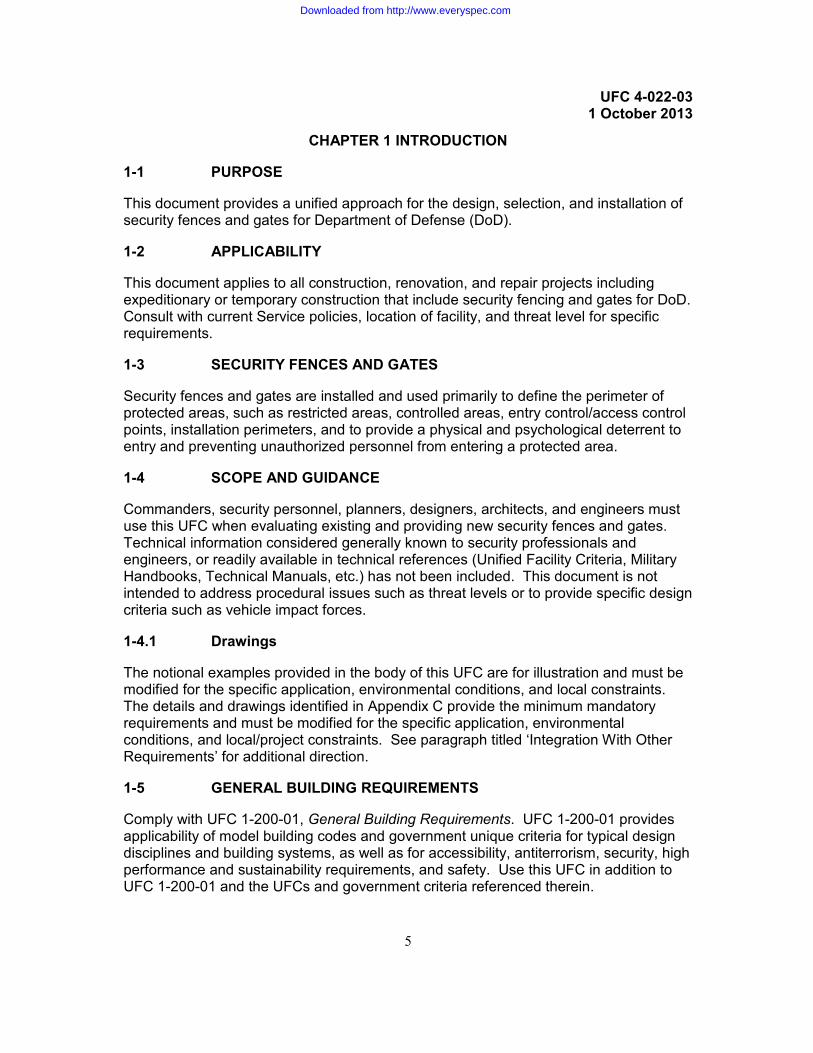
1-1 PURPOSE
This document provides a unified approach for the design, selection, and installation of security fences and gates for Department of Defense (DoD).
1-2 APPLICABILITY
This document applies to all construction, renovation, and repair projects including expeditionary or temporary construction that include security fencing and gates for DoD. Consult with current Service policies, location of facility, and threat level for specific requirements.
1-3 SECURITY FENCES AND GATES
Security fences and gates are installed and used primarily to define the perimeter of protected areas, such as restricted areas, controlled areas, entry control/access control points, installation perimeters, and to provide a physical and psychological deterrent to entry and preventing unauthorized personnel from entering a protected area.
1-4 SCOPE AND GUIDANCE
Commanders, security personnel, planners, designers, architects, and engineers must use this UFC when evaluating existing and providing new security fences and gates. Technical information considered generally known to security professionals and engineers, or readily available in technical references (Unified Facility Criteria, Military Handbooks, Technical Manuals, etc.) has not been included. This document is not intended to address procedural issues such as threat levels or to provide specific design criteria such as vehicle impact forces.
1-4.1 Drawings
The notional examples provided in the body of this UFC are for illustration and must be modified for the specific application, environmental conditions, and local constraints. The details and drawings identified in Appendix C provide the minimum mandatory requirements and must be modified for the specific application, environmental conditions, and local/project constraints. See paragraph titled ‘Integration With Other Requirements’ for additional direction.
1-5 GENERAL BUILDING REQUIREMENTS
Comply with UFC 1-200-01, General Building Requirements. UFC 1-200-01 provides applicability of model building codes and government unique criteria for typical design disciplines and building systems, as well as for accessibility, antiterrorism, security, high performance and sustainability requirements, and safety. Use this UFC in addition to UFC 1-200-01 and the UFCs and government criteria referenced therein.
Downloaded from http://www.everyspec.com
UFC 4-022-03 1 October 2013
6
This UFC is one of a series of unified facilities criteria documents that cover minimum standards, planning, preliminary design, and detailed design for security and antiterrorism. The manuals in this series are designed to be used by a diverse audience to facilitate development of projects throughout the design cycle.
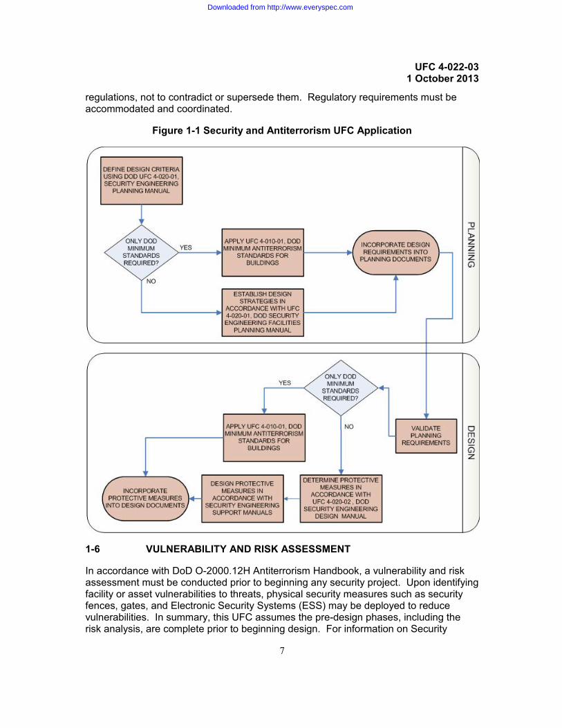
1-5.1 UFC Application
The application of the security and antiterrorism UFCs is illustrated in Figure 1-1. UFC 4-020-01 is intended to be the starting point for any project that is likely to have security or antiterrorism requirements. By beginning with UFC 4-020-01, DoD Security Engineering Facilities Planning Manual, the design criteria will be developed that establishes which of the other UFCs in the series will need to be applied. The design criteria may indicate that only the minimum standards need to be incorporated, or it may include additional requirements, resulting in the need for application of additional UFCs. Applying this series of UFCs in the manner illustrated in Figure 1-1 will result in the most efficient use of resources for protecting assets against security and antiterrorism related threats.
1-5.2 Requirements Determination
UFC 4-020-01 includes a process for defining the design criteria for a protective system that protects important assets associated with a permanent facility or one in an expeditionary environment. The design criteria will consist of the assets to be protected, the threats to those assets, the degree to which those assets will be protected against the threat, and any constraints that might be imposed on a design. The design criteria may be limited to that defined in minimum standards or it may go beyond those requirements.
Establishing the design criteria for security and antiterrorism is not something that can be done effectively by any one person. It requires a team of people to ensure that the varied interests relating to a project are considered appropriately. The specific membership of a planning team will be based on local considerations, but in general, the following functions should be represented - Facility User, Antiterrorism, Intelligence, Operations, Security, Logistics, Engineering, and Resource Management. Based on local considerations, there may be others who should be consulted for input into the design criteria. They might include Fire Marshals, communications people, environmental people, and historic preservation officers.
1-5.3 Integration With Other Requirements
Security and antiterrorism requirements will never be the only requirements associated with a project. Even where a project is specifically for security and antiterrorism upgrades, there will still be other requirements that must be considered. There will be times where one criterion is more stringent than another, in which case the more stringent one must be applied. In some cases, criteria may conflict. In those cases, those conflicts must be resolved, which may require compromise or adjustment to one or the other criteria. Many security regulations specify protective measures, policies, and operations related to security. This UFC is intended to complement those existing
Downloaded from http://www.everyspec.com
UFC 4-022-03 1 October 2013
7
regulations, not to contradict or supersede them. Regulatory requirements must be accommodated and coordinated.
Figure 1-1 Security and Antiterrorism UFC Application
1-6 VULNERABILITY AND RISK ASSESSMENT
In accordance with DoD O-2000.12H Antiterrorism Handbook, a vulnerability and risk assessment must be conducted prior to beginning any security project. Upon identifying facility or asset vulnerabilities to threats, physical security measures such as security fences, gates, and Electronic Security Systems (ESS) may be deployed to reduce vulnerabilities. In summary, this UFC assumes the pre-design phases, including the risk analysis, are complete prior to beginning design. For information on Security
Downloaded from http://www.everyspec.com

UFC 4-022-03 1 October 2013
8
Engineering Planning and Design process, refer to UFC 4-020-01 and UFC 4-020-02. The engineering risk analysis conducted as part of UFC 4-020-01 must be consistent with the terrorism risk analysis conducted by the installation security/AT staff.
1-7 POLICY REQUIREMENTS
The requirement to protect installation assets comes from DoD Instruction/Directives, Geographic Combatant Commander (GCC) Instructions, Service Instruction/Directives, and Regional or Installation requirements. Consult Headquarters, Major Command, Regional, and Installation personnel to established installation asset protection requirements.
1-7.1 Department of Defense (DoD)
There are several instructions and publications within the Department of Defense that establish requirements for access control and physical security for installation perimeter, restricted access areas and other secure areas.
1-7.1.1 DoD Physical Security Program
DoD 5200.8-R: Requires DOD Components to determine the necessary access control based on the requirements of a developed physical security program. Emergency planning is specified to include establishment of a system for positive identification of personnel and equipment authorized to enter and exit the installation and maintenance of adequate physical barriers (i.e. security fences and gates) that will be employed to control access to the installation.
1-7.1.2 Physical Security of Sensitive Conventional Arms, Ammunition, and Explosives (AA&E)
DoD 5100.76-M prescribes minimum standards and criteria for the physical security of DoD sensitive conventional AA&E. This Manual establishes the requirements to protect sensitive AA&E including perimeters, openings, and security fences.
1-7.1.3 Nuclear Facilities
DoD S-5210.41-M Vols. 1-3, AFMAN 31-108, OPNAVINST 5210.16, and AR 190-54 prescribe policy, responsibilities, procedures, and minimum standards for the security and safeguarding of DoD nuclear reactors, special nuclear materials and weapons including perimeters, openings, and security fences.
1-7.1.4 DoD Antiterrorism Program
DoDI 2000.12: Provides DoD policies for ATFP and assigns responsibilities for implementing physical security systems as part of the DoD ATFP Program. It authorized the publication of DODI 2000.16 Antiterrorism Standards as the DoD standards for ATFP and DoD O-2000.12-H DoD Antiterrorism Handbook as guidance for the DoD standards.
Downloaded from http://www.everyspec.com

UFC 4-022-03 1 October 2013
9
1-7.1.5 DoD Antiterrorism Handbook
DoD O-2000.12H: Defines the DoD Force Protection Condition (FPCON) System, which describes the potential threat levels and the applicable FPCON measures to be enacted for each level. FPCON measures in the 12-H were modified in DoDI 2000.16, Change 2 of 08 Dec 2006. DoD O-2000.12H also requires Commanders to develop and implement Random Antiterrorism Measures (RAM) as an integral part of their AT Program. This handbook provides a detailed discussion on physical security functional requirements of which physical barriers (security fences and gates) are integral.
1-7.1.6 DoD Antiterrorism Standards
DoD I 2000.16: This instruction requires the installation or activity Commanding Officer to define the access control measures at installations. Additionally, DoDI 2000.16 requires Commanders at all levels to develop as part of the physical security program and implement a comprehensive Antiterrorism (AT) Program, which must define the necessary action sets, including identification and inspection procedures, barrier requirements at each of the potential Force Protection Condition (FPCON) levels and lists the most current approved FPCONS.
1-7.2 Geographic Combatant Commander (GCC) Requirements
GCC issue requirements for Antiterrorism and physical security for installations within their area of responsibility. Ensure any such requirements are incorporated in addition to the requirements found in DoD and Service Directives/Instructions. Resolve any differences in the requirements for the design of perimeter security by applying the most stringent requirement.
1-7.3 Service Requirements
1-7.3.1 Department of Air Force
1-7.3.1.1 AFI 31-101 – Integrated Defense (ID)(FOUO)
This Instruction provides the tools to plan and execute ID. It guides personnel through a familiar 7-step risk assessment process. Furthermore, working groups that are focused on mutually-supporting components of ID, such as the antiterrorism (AT) program and resource protection program (RPP), may be combined and streamlined. This Instruction provides flexible planning and execution opportunities that allow owners/users of various Air Force assets to become actively involved in the defense of their areas; however, some assets must remain secured in accordance with higher headquarters (HHQ) directives, such as nuclear weapons; arms, ammunition and explosives (AA&E); classified information and Defense Critical Infrastructure Program (DCIP) assets.
Downloaded from http://www.everyspec.com
UFC 4-022-03 1 October 2013
10
1-7.3.1.2 AFMAN 32-1084 Civil Engineering: Facility Requirements
This Manual is a tool to assist commanders, their management, and technical staff in programming the acquisition of facilities and in managing the inventory of real property facilities and provides additional guidance for fencing/barrier requirements.
1-7.3.2 Department of the Army
1-7.3.2.1 AR 190-13 The Army Physical Security Program
Implements DOD 5200.08–R. It prescribes policies, procedures, and guidance to plan and implement the Department of the Army Physical Security Program.
1-7.3.2.2 AR 190-16 Physical Security
Establishes standard policies on physical security systems planning, threat statements, control of access to installations, security of aircraft, bulk petroleum assets, and critical communications facilities.
1-7.3.2.3 AR 190-11 Physical Security of Arms, Ammunition and Explosives
Refer to AR 190-11 for physical security criteria for conventional arms, ammunition, and explosives (AA&E) for additional guidance on fencing requirements.
1-7.3.2.4 ATTP 3-39.32 Physical Security: Army Tactics, Techniques, and Procedures (ATTP)
Provides doctrinal guidance for personnel who are responsible for planning and executing physical security programs. It is the basic reference for training security personnel and is intended to be used in conjunction with the Army Regulation (AR) 190 series (Military Police), Security and Antiterrorism Unified Facilities Criteria (UFC) publications, Department of Defense (DOD) directives, and other Department of the Army (DA) publications.
1-7.3.3 Department of the Navy including Marine Corps
1-7.3.3.1 OPNAVINST 5530.14 Navy Physical Security and Law Enforcement
The intent of this instruction is to identify responsibilities and provide guidance for the protection of people and assets throughout the Navy.
1-7.3.3.2 Physical Security of Arms, Ammunition and Explosives
Refer to OPNAVINST 5530.13 for physical security criteria for conventional arms, ammunition, and explosives (AA&E) and additional fencing requirements.
1-7.3.3.3 NTTP 3-07.2.3 Law Enforcement and Physical Security
Provides guidance for the physical security for Naval Installations to include perimeter security and restricted areas.
Downloaded from http://www.everyspec.com
UFC 4-022-03 1 October 2013
11
1-7.3.3.4 MCO 5530.14 Marine Corps Physical Security Program Manual
Provides requirements for physical security for Marine Corps installations and organizations including additional barrier/security fence requirements.
1-7.4 Installation Specific Requirements
As required by DODI 2000.16 and service directives, each installation must have an Antiterrorism Plan. The plan provides procedures and recommendations for reducing risk and vulnerability of DOD personnel, their family members, facilities, and assets from acts of terrorism. As such, the installation AT plan reflects the foundation for requirements determination. Installation specific requirements need to be factored into all capital improvement initiatives.
1-7.5 Airfield Requirements
For Air National Guard (ANG) and Air Force Reserve Command (AFRC) units that are co-located with civilian airports, the airfield side of the restricted areas does not require fencing installation as it is prohibited by the Federal Aviation Agency (FAA) safety requirements. Fencing requirements for airports and heliports are provided in UFC 4-141-10N and UFC 3-260-01.
1-8 PHYSICAL SECURITY
That part of security concerned with physical measures designed to safeguard personnel; to prevent or delay unauthorized access to equipment, installations, material, and documents; and to safeguard them against espionage, sabotage, damage, and theft.
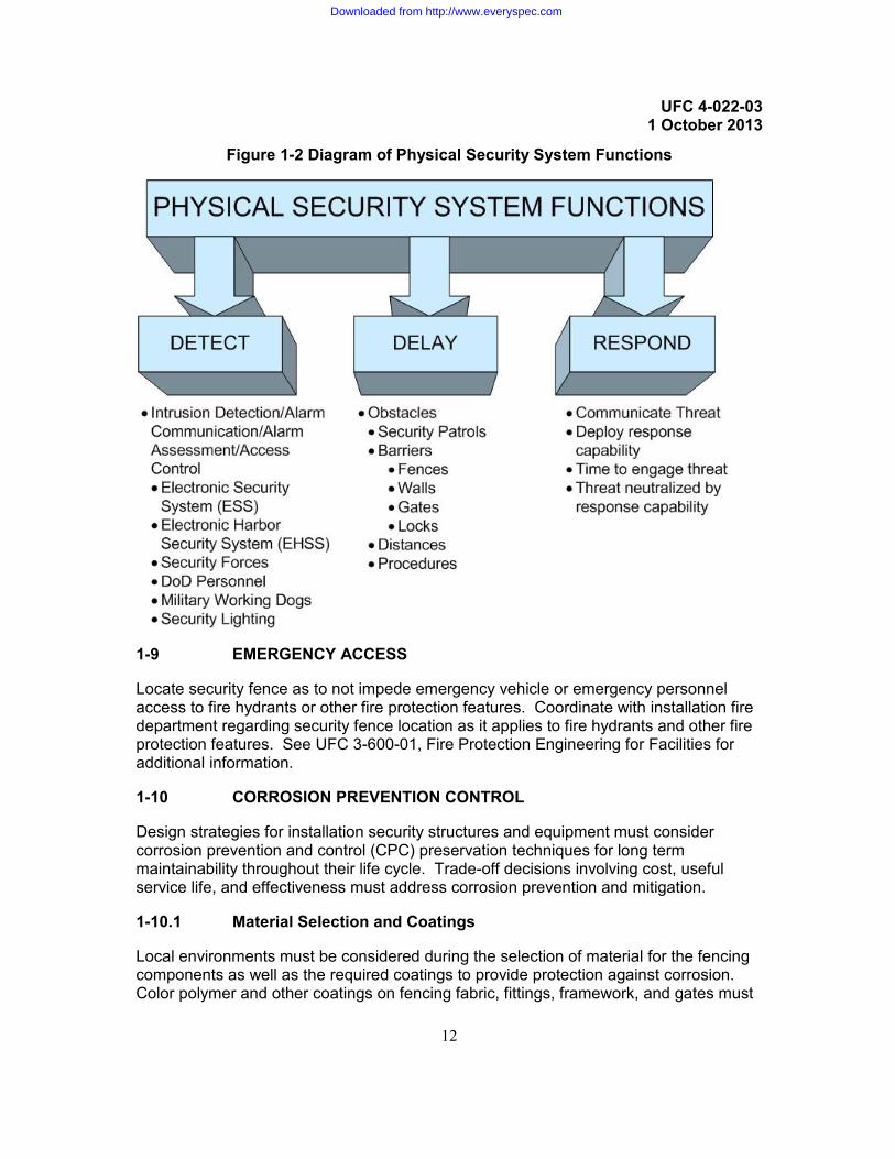
1-8.1 Physical Security System
A system comprised of people, equipment, and operational procedures that control access to critical facilities or assets. Fences are but one of many elements that comprise the equipment component of a physical security system. Figure 1-2 diagrams some of the additional components of a physical security system.
From Figure 1-2, fencing is considered part of the delay function of the overall Physical Security System. However, standard chain-link fencing provides approximately 7- 15 seconds of delay.
Downloaded from http://www.everyspec.com
UFC 4-022-03 1 October 2013
12
Figure 1-2 Diagram of Physical Security System Functions
1-9 EMERGENCY ACCESS
Locate security fence as to not impede emergency vehicle or emergency personnel access to fire hydrants or other fire protection features. Coordinate with installation fire department regarding security fence location as it applies to fire hydrants and other fire protection features. See UFC 3-600-01, Fire Protection Engineering for Facilities for additional information.
1-10 CORROSION PREVENTION CONTROL
Design strategies for installation security structures and equipment must consider corrosion prevention and control (CPC) preservation techniques for long term maintainability throughout their life cycle. Trade-off decisions involving cost, useful service life, and effectiveness must address corrosion prevention and mitigation.
1-10.1 Material Selection and Coatings
Local environments must be considered during the selection of material for the fencing components as well as the required coatings to provide protection against corrosion. Color polymer and other coatings on fencing fabric, fittings, framework, and gates must
Downloaded from http://www.everyspec.com
UFC 4-022-03 1 October 2013
13
be applied to enhance visibility and provide greater corrosion resistance, especially in corrosive or salt laden environment. Appendix B defines this environment.
Coating on any fasteners or ties must be electrolytically compatible with fencing fabric to inhibit corrosion. All security fence fittings must be electrolytically compatible with all fence components. Regarding drainage openings (ditches, culverts, vents, metal ducts/pipes, and other opening) consideration must be given to the materials used (smaller metal pipe, metal/steel grillage) in securing such openings. One of the most important corrosion issues is the chemical reaction between dissimilar metals. When dissimilar metals are in contact with one another in the presence of an electrolyte, galvanic action occurs, resulting in the deterioration. The electrolyte may be rain water running from one surface to another, or moisture from the air containing enough acid to cause it to act as an electrolyte. See Appendix A for material specifications.
1-11 REFERENCES
Appendix A contains a list of references used in this document. The publication date of the code or standard is not included in this document. In general, the latest available issuance of the reference is used.
1-12 GLOSSARY
Appendix B contains definitions of terms.
Downloaded from http://www.everyspec.com

UFC 4-022-03 1 October 2013
14
This Page Intentionally Left Blank
Downloaded from http://www.everyspec.com
UFC 4-022-03 1 October 2013
15
CHAPTER 2 FENCING
2-1 FUNCTION
The physical security barrier provided by a security fence provides one or more of the following functions:
x Gives notice of legal boundary of the outermost limits of the protected area. x Assists in controlling and screening authorized entries into secured/protected
areas by channeling vehicles and personnel to access control points. x Supports surveillance, detection, assessment, and other security functions by
providing a platform for installing intrusion detection equipment. x Deters casual intruders from penetrating a secured/protected area by presenting
a barrier that requires an overt action to enter. x Causes a delay to obtain access to a installation/facility, thereby increasing the
probability of detection.
2-2 CHAIN LINK FENCING
Chain link fence is a fencing material made from wire helically wound and interwoven in such a manner as to provide a continuous mesh without knots or ties. See Figure 2-1 below for standard chain link fence details identifying all of the components.
Chain link fences and gates must comply with specification requirements in UFGS 32 31 13, Chain Link Fences and Gates and UFGS 32 31 13.53, High-Security Chain Link Fences and Gates. Consult with ASTM F2611 and ASTM F1712 for additional guidance (fabric, post, framework, fittings, and other accessories) regarding chain link fencing. Refer also to the Chain Link Manufacturers Institute’s Security Fencing Recommendations (CLF-SFR0111) and Product Manual (CLF0PM0610) for additional information.
2-2.1 Chain Link Fencing Fabric
Fencing fabric must be minimum 9-gage wire mesh and mesh openings must be not be greater than 2-inches (51 mm) per side. Fence fabric material will be galvanized steel, PVC coated steel fabric (use PVC coated if located in corrosive environment or where aesthetics are of prime importance), or aluminum coated steel fabric (use aluminum coated if located in corrosive environment). See Corrosion Prevention Control for additional information regarding material selection.
2-2.1.1 Additional Fencing Fabric Requirements
The fencing fabric must be extended to within 2 inches (51 mm) of firm ground and anchored, if required by service requirements, using horizontal bottom rails, tension wires, concrete curbs, sills, sheet piling, piping, or other inexpensive materials. For additional security burying the fabric 12 inches (305 mm) may also be considered; however, corrosion of the buried fabric must be monitored. This anchoring will prevent
Downloaded from http://www.everyspec.com
UFC 4-022-03 1 October 2013
16
the fencing fabric from being able to be lifted by hand more than 5 inches (125 mm) in height. Horizontal bottom rails, concrete curbs, or sills can assist in mitigating an intruder from lifting the fence fabric beyond the requirement above. Mesh openings in chain link fencing are intended to not be covered, blocked, or laced with material which would prevent a clear view of personnel, vehicles, or material in outer clear zones.
Locate all posts, rails, bracing and tension wires on the secure/protected side, i.e. inner side, of the fencing fabric. Select the framework components and material from ASTM F626, ASTM F1043, and ASTM F1083.
Downloaded from http://www.everyspec.com

UFC 4-022-03 1 October 2013
17
Figure 2-1: General Chain-Link Fence Components
1 Fabric
2 Selvage
3 Corner Post
4 Barbed Wire/Barbed Tape
5 Outrigger/Barbed Wire Arm
6 Tension Wire (Top and Bottom)
7 Hog Ring
8 Truss Rod
9 Line Post
10 Tie Wire
11 Tension Bar
12 Tension Clip
13 Concrete Footing
Downloaded from http://www.everyspec.com
UFC 4-022-03 1 October 2013
18
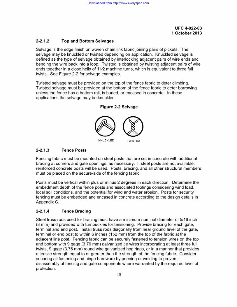
2-2.1.2 Top and Bottom Selvages
Selvage is the edge finish on woven chain link fabric joining pairs of pickets. The selvage may be knuckled or twisted depending on application. Knuckled selvage is defined as the type of selvage obtained by interlocking adjacent pairs of wire ends and bending the wire back into a loop. Twisted is obtained by twisting adjacent pairs of wire HQGV�WRJHWKHU�LQ�D�FORVH�KHOL[�RI���»��PDFKLQH�WXUQV��ZKLFK�LV�HTXLYDOHQW�WR�WKUHH�IXOO�twists. See Figure 2-2 for selvage examples.
Twisted selvage must be provided on the top of the fence fabric to deter climbing. Twisted selvage must be provided at the bottom of the fence fabric to deter borrowing unless the fence has a bottom rail, is buried, or encased in concrete. In these applications the selvage may be knuckled.
Figure 2-2 Selvage
2-2.1.3 Fence Posts
Fencing fabric must be mounted on steel posts that are set in concrete with additional bracing at corners and gate openings, as necessary. If steel posts are not available, reinforced concrete posts will be used. Posts, bracing, and all other structural members must be placed on the secure-side of the fencing fabric.
Posts must be vertical within plus or minus 2 degrees in each direction. Determine the embedment depth of the fence posts and associated footings considering wind load, local soil conditions, and the potential for wind and water erosion. Posts for security fencing must be embedded and encased in concrete according to the design details in Appendix C.
2-2.1.4 Fence Bracing
Steel truss rods used for bracing must have a minimum nominal diameter of 5/16 inch (8 mm) and provided with turnbuckles for tensioning. Provide bracing for each gate, terminal and end post. Install truss rods diagonally from near ground level of the gate, terminal or end post to within 6 inches (152 mm) from the top of the fabric at the adjacent line post. Fencing fabric can be securely fastened to tension wires on the top and bottom with 9 gage (3.76 mm) galvanized tie wires incorporating at least three full twists, 9 gage (3.76 mm) round wire galvanized hog rings, or in a manner that provides a tensile strength equal to or greater than the strength of the fencing fabric. Consider securing all fastening and hinge hardware by peening or welding to prevent disassembly of fencing and gate components where warranted by the required level of protection.
Downloaded from http://www.everyspec.com
UFC 4-022-03 1 October 2013
19
See Appendix C for design details of chain link fencing posts, rails, braces, and tension wires.
2-3 ORNAMENTAL FENCES
Ornamental (also known as tubular) fencing provides a greater resistance to climbing as well as providing aesthetic qualities in comparison to chain link fencing. Ornamental fencing systems are constructed of either steel or aluminum components. Install ornamental fence pickets plumb and provide a minimum of 2 inches (51 mm) or maximum of 6 inches (152 mm) between the fence and the ground. See ASTM F2408 for additional guidance for ornamental fence systems. See Appendix C for design details of ornamental fence.
2-4 WELDED WIRE MESH FABRIC FENCING
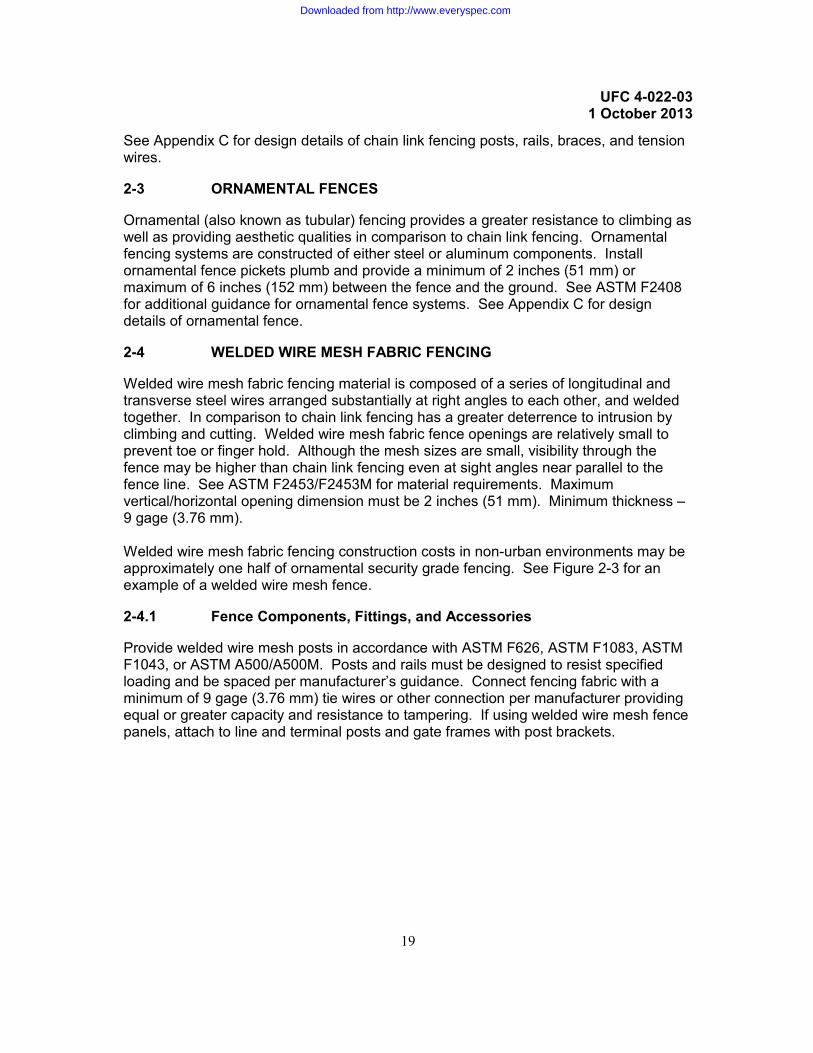
Welded wire mesh fabric fencing material is composed of a series of longitudinal and transverse steel wires arranged substantially at right angles to each other, and welded together. In comparison to chain link fencing has a greater deterrence to intrusion by climbing and cutting. Welded wire mesh fabric fence openings are relatively small to prevent toe or finger hold. Although the mesh sizes are small, visibility through the fence may be higher than chain link fencing even at sight angles near parallel to the fence line. See ASTM F2453/F2453M for material requirements. Maximum vertical/horizontal opening dimension must be 2 inches (51 mm). Minimum thickness – 9 gage (3.76 mm). Welded wire mesh fabric fencing construction costs in non-urban environments may be approximately one half of ornamental security grade fencing. See Figure 2-3 for an example of a welded wire mesh fence.
2-4.1 Fence Components, Fittings, and Accessories
Provide welded wire mesh posts in accordance with ASTM F626, ASTM F1083, ASTM F1043, or ASTM A500/A500M. Posts and rails must be designed to resist specified loading and be spaced per manufacturer’s guidance. Connect fencing fabric with a minimum of 9 gage (3.76 mm) tie wires or other connection per manufacturer providing equal or greater capacity and resistance to tampering. If using welded wire mesh fence panels, attach to line and terminal posts and gate frames with post brackets.
Downloaded from http://www.everyspec.com
UFC 4-022-03 1 October 2013
20
Figure 2-3: Welded Wire Mesh Fence
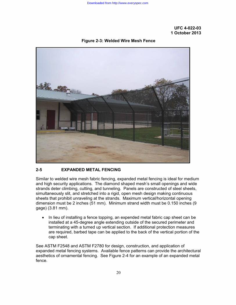
2-5 EXPANDED METAL FENCING
Similar to welded wire mesh fabric fencing, expanded metal fencing is ideal for medium and high security applications. The diamond shaped mesh’s small openings and wide strands deter climbing, cutting, and tunneling. Panels are constructed of steel sheets, simultaneously slit, and stretched into a rigid, open mesh design making continuous sheets that prohibit unraveling at the strands. Maximum vertical/horizontal opening dimension must be 2 inches (51 mm). Minimum strand width must be 0.150 inches (9 gage) (3.81 mm).
x In lieu of installing a fence topping, an expended metal fabric cap sheet can be installed at a 45-degree angle extending outside of the secured perimeter and terminating with a turned up vertical section. If additional protection measures are required, barbed tape can be applied to the back of the vertical portion of the cap sheet.
See ASTM F2548 and ASTM F2780 for design, construction, and application of expanded metal fencing systems. Available fence patterns can provide the architectural aesthetics of ornamental fencing. See Figure 2-4 for an example of an expanded metal fence.
Downloaded from http://www.everyspec.com
UFC 4-022-03 1 October 2013
21
2-5.1 Retrofit Existing Fence
Expanded metal fencing can be applied as a retrofit to existing chain link fencing and gates to provide additional protection, strength, and durability. Expanded metal fencing should be installed directly to the existing fence utilizing the installed chain link fence fabric and framework.
2-5.2 Fence Components, Fittings, and Accessories
Line and terminal posts must be hot-dip galvanized in accordance with ASTM F626, ASTM F1043, and ASTM F1083. The manufacturer’s recommendation must be considered when spacing line posts. Top, middle, and bottom rails must be hot-dip galvanized. Rails can be fastened to posts using clamps. Standard weight piping must be used for the posts and rails of expanded metal fencing. Fittings such as line rail clamps, post caps, tension bands, and panel clamps must be galvanized, heavy pressed steel or malleable iron.
Figure 2-4: Expanded Metal Fence
2-6 FARM STYLE FENCES
Farm style fences are constructed of wood and/or metal posts and wire. Farm style fences, barb wire, and woven wire must comply with specification requirements in UFGS 32 31 26, Wire Fences and Gates and the drawings in Appendix C. Pressure treat all wood posts and metal posts must be zinc coated and conform to ASTM A702. Steel post conforming to ASTM F1043 must be used in conjunction with T-section or U-section line post. The gates are constructed of 1 5/8 inch (41.3 mm) minimum diameter tubular steel, and secured with a chain and padlock.
See Appendix C for design details of farm-style fence.
2-7 EXPEDITIONARY PERIMETER FENCING
Refer to GTA 90-01-011, Joint Forward Operations Base (JFOB) Survivability and Protective Construction Handbook for perimeter security requirements.
Downloaded from http://www.everyspec.com
UFC 4-022-03 1 October 2013
22
2-8 FENCE FABRIC HEIGHT
Unless otherwise directed all security and perimeter fencing must have a minimum fence fabric height of 7 feet (2.13m), excluding the top guard. Fence height including outriggers must be a minimum of 8 feet (2.44m). Modifications to existing fences are not required to meet this new UFC.
Consult with current Service policies on specific requirements regarding fence height and assets that may require a higher level of protection.
2-9 TOP GUARDS
When required, install outriggers (support arms) at 45-degree angles in a single arm (towards the threat side) or “Y”/”V” configuration, constructed of a single or double outrigger consisting of 18-inch (457 mm) arm(s), each having three strands of barbed wire at regular intervals along the top of the fence.
The outriggers must provide a minimum of an additional 12 inches (305 mm) to the fence height. The top guard fencing adjoining gates may range from a vertical height of 18 inches (457 mm) to the normal 45 degree outward protection, but for a limited distance along the fence line to adequately open the gates. Outriggers must be permanently affixed to the fence posts with screws or by spot welding. Screws used to affix outriggers to posts must be made tamper-proof either by design, peening, or welding.
2-9.1 Outrigger/Barbed Wire Arm Material Specifications
Top guards must be constructed of the same material as the other fencing components in accordance to ASTM F626. See Appendix C for details.
2-9.2 Barbed Wire and Barbed Tape Concertina
Barbed wire is a fabricated wire product consisting of two line wires twisted to form a two-wire strand, into which 2–point or 4–point barbs are tightly wrapped and locked into place at specific intervals.
Barbed tape concertina is a strip of metal, machined to produce clusters of sharp points. Provide three strands of barbed wire, equally spaced, on outrigger/support arms where barbed tape/concertina is mounted.
2-9.2.1 Barbed Wire
Fences requiring barbed wire must use a minimum of 3 strands of barbed wire equally spaced. Additional strands may be added as required. Barbed wire must consist of two 12.5 -gage /0.099-inch (2.5 mm) (+0. 005- inch (.127 mm)) twisted line wires with 15-gage /0.080- inch (2 mm)(+0, 005-inch (.127 mm)) round barbs. Barbed wire must be zinc-coated steel, aluminum coated steel, aluminum alloy, or PVC over zinc-coated steel as specified. All barbs must consist of four points and spacing of barbs must be at 5- inch (127 mm) (+1- inch (25.4 mm)) centers.
Downloaded from http://www.everyspec.com
UFC 4-022-03 1 October 2013
23
2-9.2.1.1 Barbed Wire Material Specifications
Barbed wire must be in accordance to ASTM A121 and ASTM F1665. See Appendix C for barbed wire support configurations.
2-9.2.2 Barbed Tape/Concertina
Barbed-tape concertina is a commercially manufactured wire coil constructed of high-strength-steel barbed wire that is clipped together at intervals to form a single coil or double coil. The single coil must be a minimum of 2 feet (610 mm) in diameter and extend at least 50 feet (15.2 m) without permanent distortion. Double coil must be 24/30 inch (610 mm/762 mm) and extend at least 50 feet (15.2 m) without permanent distortion.
Barbed tape concertina may be added to the top and, in some cases, to the bottom to increase the level of protection. Barbed tape concertina must be secured at a minimum interval of 18 inches (457 mm) along the fence fabric to the top barbed wire strand and a maximum gap of 2 inches (51 mm) must be maintained between the bottom barbed wire and the top of the chain-link fabric. After use, barbed tape concertina may be recoiled and reused without distortion. For additional protection, barbed tape concertina may be installed between the “Y” configuration of the outriggers.
2-9.2.2.1 Barbed Tape/Concertina Material Specifications
Barbed tape concertina must be in accordance to ASTM F1911 and ASTM F1910. See Appendix C barbed tape configurations.
2-9.2.3 Specific Barb Requirements
2-9.2.3.1 Farm Style Fence
Any barbs used with farm fencing must be a minimum of 15.5 gage wire. Barbed clusters must have a minimum width of 1.2 inches (30.7 mm). The distance between these strands is intended not to exceed 6 inches (152 mm) and at least one wire must be interlaced vertically and midway between posts. The ends of the barbed wire strands may be staggered or fastened together, and the base wire may be picketed to the ground. See Appendix C for barbed wire details.
2-9.2.3.2 Barb Wire Fencing
3, 4, or 5-strand barbed wire fencing, 4 feet (1.2 m) high, should be used for extensions of flight-line area barriers, perimeter boundary for isolated portions of installations, livestock barrier, and area boundary for on-base bulk material storage areas. Barbed wire fastened on wooden posts may use a minimum of 1.5 inch (38 mm) staples made from the same metal as the wire for fastening. See Appendix C for barbed wire details.
2-9.2.3.3 Temporary Usage
When used for temporary purposes (not used as fence topper), concertina wire should be used in multiple stacked coils. Stacked concertina wire on perimeter barriers may be
Downloaded from http://www.everyspec.com
UFC 4-022-03 1 October 2013
24
laid between poles with one roll on top of another or in a pyramid arrangement (minimum of 3 rolls). Concertina blades must have a minimum length of 1.2 inches (30.7 mm).
Barbed tape concertina as an expedient measure for short-term use, pending the erection of permanent fencing, can be non-reinforced. Reinforce all barbed tape concertina used for permanent security applications.
2-10 GROUNDING
Grounding and bonding of the perimeter systems must be in accordance with the National Electric Safety Code (NESC) - IEEE C2. Fences that are required to be grounded by NESC must be designed to limit touch, step, and transferred voltages in accordance with industry practices. IEEE Std 80™-2000 - IEEE Guide for Safety in AC Substation Grounding is one source that may be utilized to provide guidance in meeting these requirements.
The grounding connections must be made either to the grounding system of the enclosed equipment or to a separate ground.
1. Fences must be grounded at each side of a gate or other opening. 2. Gates must be bonded to the grounding conductor, jumper, or fence. 3. A buried bonding jumper must be used to bond across a gate or other
opening in the fence, unless a nonconducting fence section is used. 4. If barbed wire strands are used above the fence fabric, the barbed wire
strands must be bonded to the grounding conductor, jumper, or fence. 5. When fence posts are of conducting material, the grounding conductor must
be connected to the fence post or posts, as required, with suitable connecting means
6. When fence posts are of nonconducting material, suitable bonding connection must be made to the fence mesh strands and the barbed wire strands at each grounding conductor point.
2-11 REINFORCEMENT FOR FENCING
Refer to UFC 4-022-01 and 4-022-02 for additional guidance and requirements (number and size of cables) on fence reinforcement for identified moving vehicle threat. For fabric type fences install fence reinforcement between fence fabric and fence post. For both fabric type and ornamental fences reinforcement must be installed on exterior side of fence post. If located in a corrosive environment, coated or sheathed cable may be used; however, the sheathing must be removed at the connections. See Figures 2-5/2-6 and Appendix C for design details of fence reinforcement. See Appendix A for material specifications.
Downloaded from http://www.everyspec.com
UFC 4-022-03 1 October 2013
25
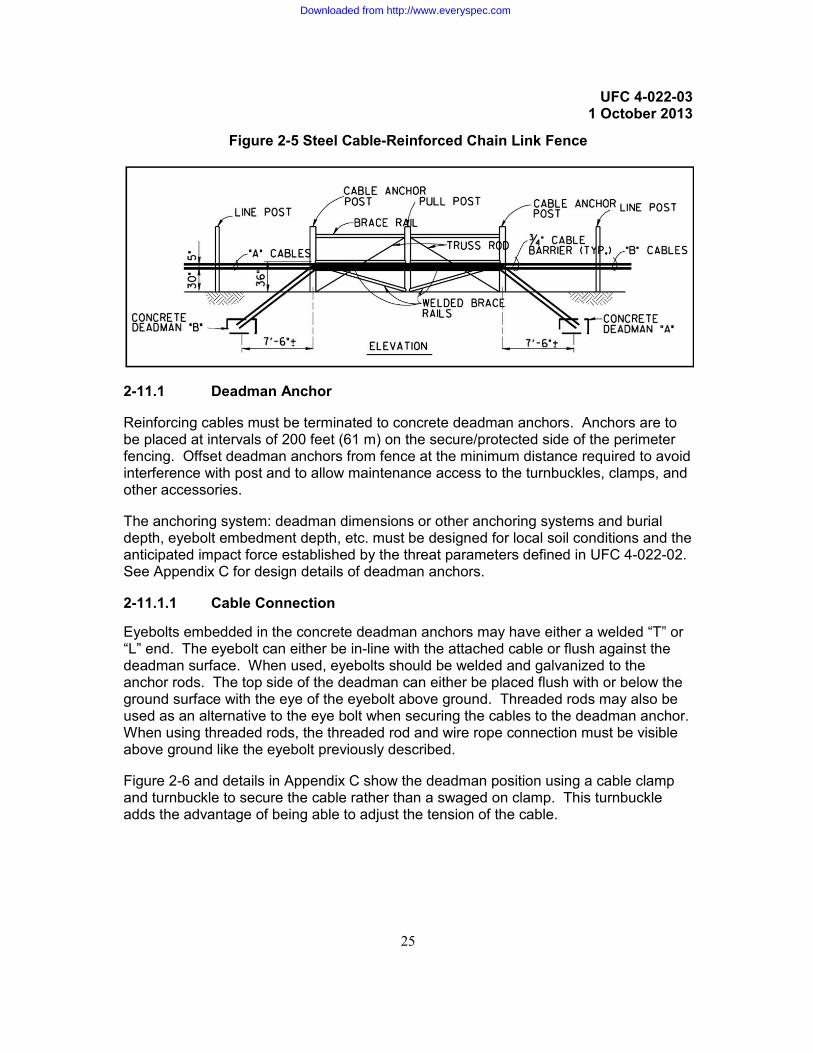
Figure 2-5 Steel Cable-Reinforced Chain Link Fence
2-11.1 Deadman Anchor
Reinforcing cables must be terminated to concrete deadman anchors. Anchors are to be placed at intervals of 200 feet (61 m) on the secure/protected side of the perimeter fencing. Offset deadman anchors from fence at the minimum distance required to avoid interference with post and to allow maintenance access to the turnbuckles, clamps, and other accessories.
The anchoring system: deadman dimensions or other anchoring systems and burial depth, eyebolt embedment depth, etc. must be designed for local soil conditions and the anticipated impact force established by the threat parameters defined in UFC 4-022-02. See Appendix C for design details of deadman anchors.
2-11.1.1 Cable Connection
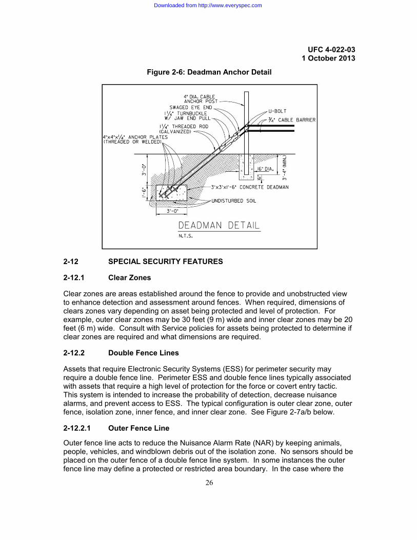
Eyebolts embedded in the concrete deadman anchors may have either a welded “T” or “L” end. The eyebolt can either be in-line with the attached cable or flush against the deadman surface. When used, eyebolts should be welded and galvanized to the anchor rods. The top side of the deadman can either be placed flush with or below the ground surface with the eye of the eyebolt above ground. Threaded rods may also be used as an alternative to the eye bolt when securing the cables to the deadman anchor. When using threaded rods, the threaded rod and wire rope connection must be visible above ground like the eyebolt previously described.
Figure 2-6 and details in Appendix C show the deadman position using a cable clamp and turnbuckle to secure the cable rather than a swaged on clamp. This turnbuckle adds the advantage of being able to adjust the tension of the cable.
Downloaded from http://www.everyspec.com
UFC 4-022-03 1 October 2013
26
Figure 2-6: Deadman Anchor Detail
2-12 SPECIAL SECURITY FEATURES
2-12.1 Clear Zones
Clear zones are areas established around the fence to provide and unobstructed view to enhance detection and assessment around fences. When required, dimensions of clears zones vary depending on asset being protected and level of protection. For example, outer clear zones may be 30 feet (9 m) wide and inner clear zones may be 20 feet (6 m) wide. Consult with Service policies for assets being protected to determine if clear zones are required and what dimensions are required.
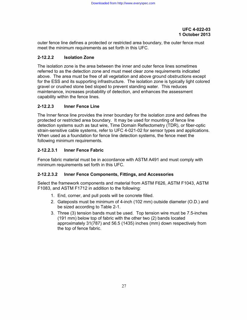
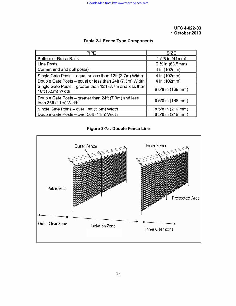
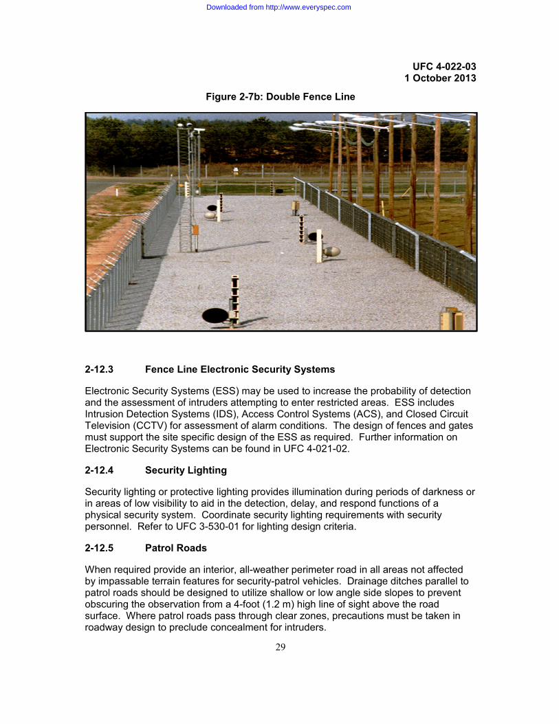
2-12.2 Double Fence Lines
Assets that require Electronic Security Systems (ESS) for perimeter security may require a double fence line. Perimeter ESS and double fence lines typically associated with assets that require a high level of protection for the force or covert entry tactic. This system is intended to increase the probability of detection, decrease nuisance alarms, and prevent access to ESS. The typical configuration is outer clear zone, outer fence, isolation zone, inner fence, and inner clear zone. See Figure 2-7a/b below.
2-12.2.1 Outer Fence Line
Outer fence line acts to reduce the Nuisance Alarm Rate (NAR) by keeping animals, people, vehicles, and windblown debris out of the isolation zone. No sensors should be placed on the outer fence of a double fence line system. In some instances the outer fence line may define a protected or restricted area boundary. In the case where the
Downloaded from http://www.everyspec.com
UFC 4-022-03 1 October 2013
27
outer fence line defines a protected or restricted area boundary, the outer fence must meet the minimum requirements as set forth in this UFC.
2-12.2.2 Isolation Zone
The isolation zone is the area between the inner and outer fence lines sometimes referred to as the detection zone and must meet clear zone requirements indicated above. The area must be free of all vegetation and above ground obstructions except for the ESS and its supporting infrastructure. The isolation zone is typically light colored gravel or crushed stone bed sloped to prevent standing water. This reduces maintenance, increases probability of detection, and enhances the assessment capability within the fence lines.
2-12.2.3 Inner Fence Line
The Inner fence line provides the inner boundary for the isolation zone and defines the protected or restricted area boundary. It may be used for mounting of fence line detection systems such as taut wire, Time Domain Reflectometry (TDR), or fiber-optic strain-sensitive cable systems, refer to UFC 4-021-02 for sensor types and applications. When used as a foundation for fence line detection systems, the fence meet the following minimum requirements.
2-12.2.3.1 Inner Fence Fabric
Fence fabric material must be in accordance with ASTM A491 and must comply with minimum requirements set forth in this UFC.
2-12.2.3.2 Inner Fence Components, Fittings, and Accessories
Select the framework components and material from ASTM F626, ASTM F1043, ASTM F1083, and ASTM F1712 in addition to the following:
1. End, corner, and pull posts will be concrete filled. 2. Gateposts must be minimum of 4-inch (102 mm) outside diameter (O.D.) and
be sized according to Table 2-1. 3. Three (3) tension bands must be used. Top tension wire must be 7.5-inches
(191 mm) below top of fabric with the other two (2) bands located approximately 31(787) and 56.5 (1435) inches (mm) down respectively from the top of fence fabric.
Downloaded from http://www.everyspec.com
UFC 4-022-03 1 October 2013
28
Table 2-1 Fence Type Components
Figure 2-7a: Double Fence Line
PIPE SIZE Bottom or Brace Rails 1 5/8 in (41mm) Line Posts 2 ½ in (63.5mm) Corner, end and pull posts) 4 in (102mm) Single Gate Posts – equal or less than 12ft (3.7m) Width 4 in (102mm) Double Gate Posts – equal or less than 24ft (7.3m) Width 4 in (102mm) Single Gate Posts – greater than 12ft (3.7m and less than 18ft (5.5m) Width 6 5/8 in (168 mm)
Double Gate Posts – greater than 24ft (7.3m) and less than 36ft (11m) Width 6 5/8 in (168 mm)
Single Gate Posts – over 18ft (5.5m) Width 8 5/8 in (219 mm) Double Gate Posts – over 36ft (11m) Width 8 5/8 in (219 mm)
Downloaded from http://www.everyspec.com
UFC 4-022-03 1 October 2013
29
Figure 2-7b: Double Fence Line
2-12.3 Fence Line Electronic Security Systems
Electronic Security Systems (ESS) may be used to increase the probability of detection and the assessment of intruders attempting to enter restricted areas. ESS includes Intrusion Detection Systems (IDS), Access Control Systems (ACS), and Closed Circuit Television (CCTV) for assessment of alarm conditions. The design of fences and gates must support the site specific design of the ESS as required. Further information on Electronic Security Systems can be found in UFC 4-021-02.
2-12.4 Security Lighting
Security lighting or protective lighting provides illumination during periods of darkness or in areas of low visibility to aid in the detection, delay, and respond functions of a physical security system. Coordinate security lighting requirements with security personnel. Refer to UFC 3-530-01 for lighting design criteria.
2-12.5 Patrol Roads
When required provide an interior, all-weather perimeter road in all areas not affected by impassable terrain features for security-patrol vehicles. Drainage ditches parallel to patrol roads should be designed to utilize shallow or low angle side slopes to prevent obscuring the observation from a 4-foot (1.2 m) high line of sight above the road surface. Where patrol roads pass through clear zones, precautions must be taken in roadway design to preclude concealment for intruders.
Downloaded from http://www.everyspec.com
UFC 4-022-03 1 October 2013
30
2-12.6 Drainage Culverts and Utility Openings
Provide protective measures for culverts, storm drains, sewers, air intakes, exhaust tunnels, and utility openings, that have a cross-section area of 96 square inches (61,939 square mm) or greater, with the smallest dimension being more than 6 inches (152.4 mm) and :
1. Pass through clear zones. 2. Traverse under or through security fences.
Such openings and barrier penetrations will be protected by securely fastened grills, locked manhole covers, or equivalent means to prevent entry or provide forced entry penetration resistance equal that of the fence. Regarding material selection for securing openings/penetrations see Material Selection and Coatings.
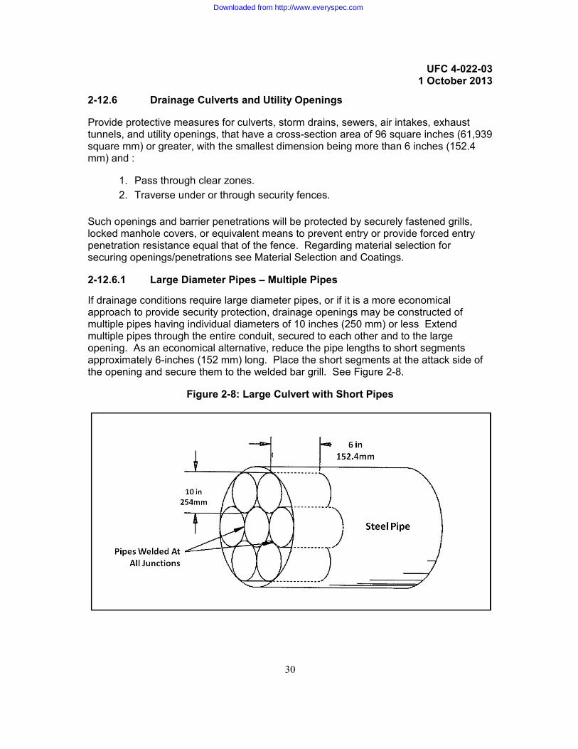
2-12.6.1 Large Diameter Pipes – Multiple Pipes
If drainage conditions require large diameter pipes, or if it is a more economical approach to provide security protection, drainage openings may be constructed of multiple pipes having individual diameters of 10 inches (250 mm) or less Extend multiple pipes through the entire conduit, secured to each other and to the large opening. As an economical alternative, reduce the pipe lengths to short segments approximately 6-inches (152 mm) long. Place the short segments at the attack side of the opening and secure them to the welded bar grill. See Figure 2-8.
Figure 2-8: Large Culvert with Short Pipes
Downloaded from http://www.everyspec.com
UFC 4-022-03 1 October 2013
31
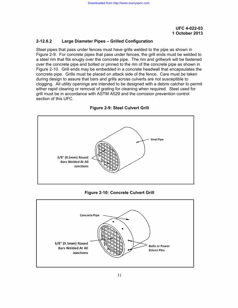
2-12.6.2 Large Diameter Pipes – Grilled Configuration
Steel pipes that pass under fences must have grills welded to the pipe as shown in Figure 2-9. For concrete pipes that pass under fences, the grill ends must be welded to a steel rim that fits snugly over the concrete pipe. The rim and grillwork will be fastened over the concrete pipe and bolted or pinned to the rim of the concrete pipe as shown in Figure 2-10. Grill ends may be embedded in a concrete headwall that encapsulates the concrete pipe. Grills must be placed on attack side of the fence. Care must be taken during design to assure that bars and grills across culverts are not susceptible to clogging. All utility openings are intended to be designed with a debris catcher to permit either rapid clearing or removal of grating for cleaning when required. Steel used for grill must be in accordance with ASTM A529 and the corrosion prevention control section of this UFC.
Figure 2-9: Steel Culvert Grill
Figure 2-10: Concrete Culvert Grill
Downloaded from http://www.everyspec.com
UFC 4-022-03 1 October 2013
32
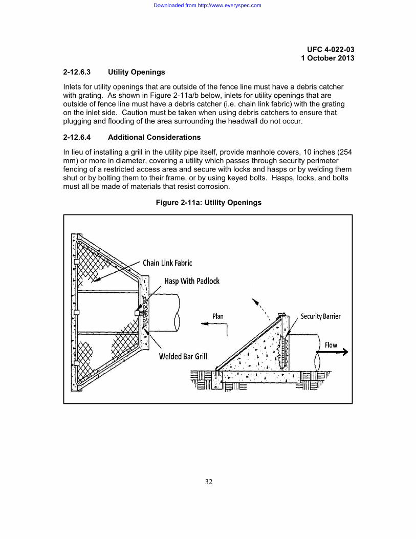
2-12.6.3 Utility Openings
Inlets for utility openings that are outside of the fence line must have a debris catcher with grating. As shown in Figure 2-11a/b below, inlets for utility openings that are outside of fence line must have a debris catcher (i.e. chain link fabric) with the grating on the inlet side. Caution must be taken when using debris catchers to ensure that plugging and flooding of the area surrounding the headwall do not occur.
2-12.6.4 Additional Considerations
In lieu of installing a grill in the utility pipe itself, provide manhole covers, 10 inches (254 mm) or more in diameter, covering a utility which passes through security perimeter fencing of a restricted access area and secure with locks and hasps or by welding them shut or by bolting them to their frame, or by using keyed bolts. Hasps, locks, and bolts must all be made of materials that resist corrosion.
Figure 2-11a: Utility Openings
Downloaded from http://www.everyspec.com

UFC 4-022-03 1 October 2013
33
Figure 2-11b: Utility Openings
2-12.7 Drainage Crossing
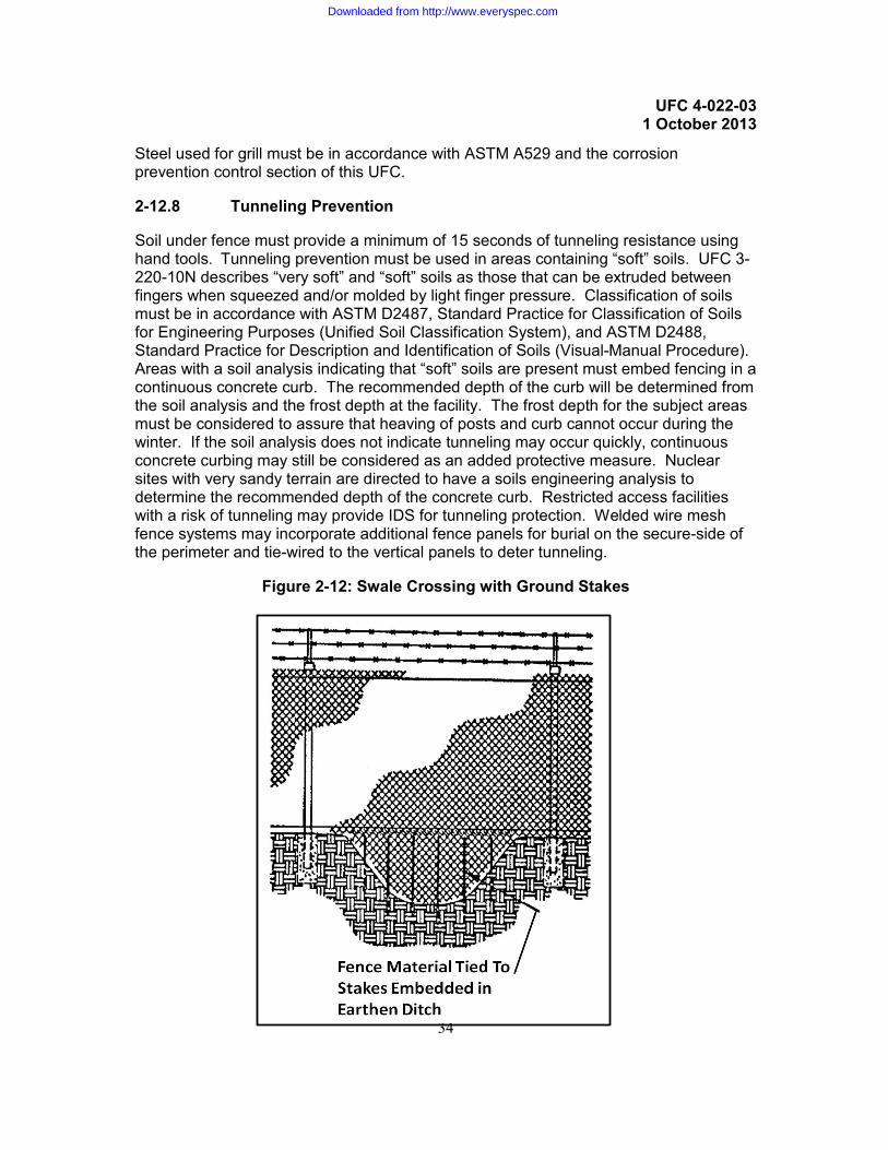
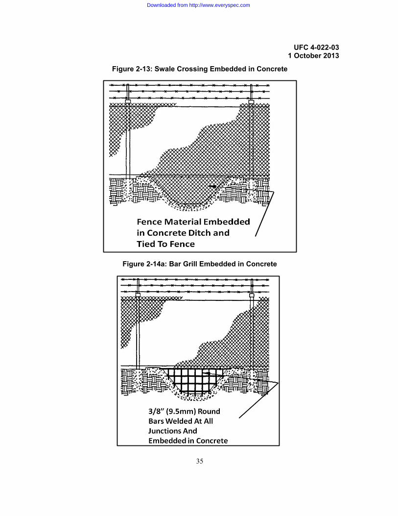
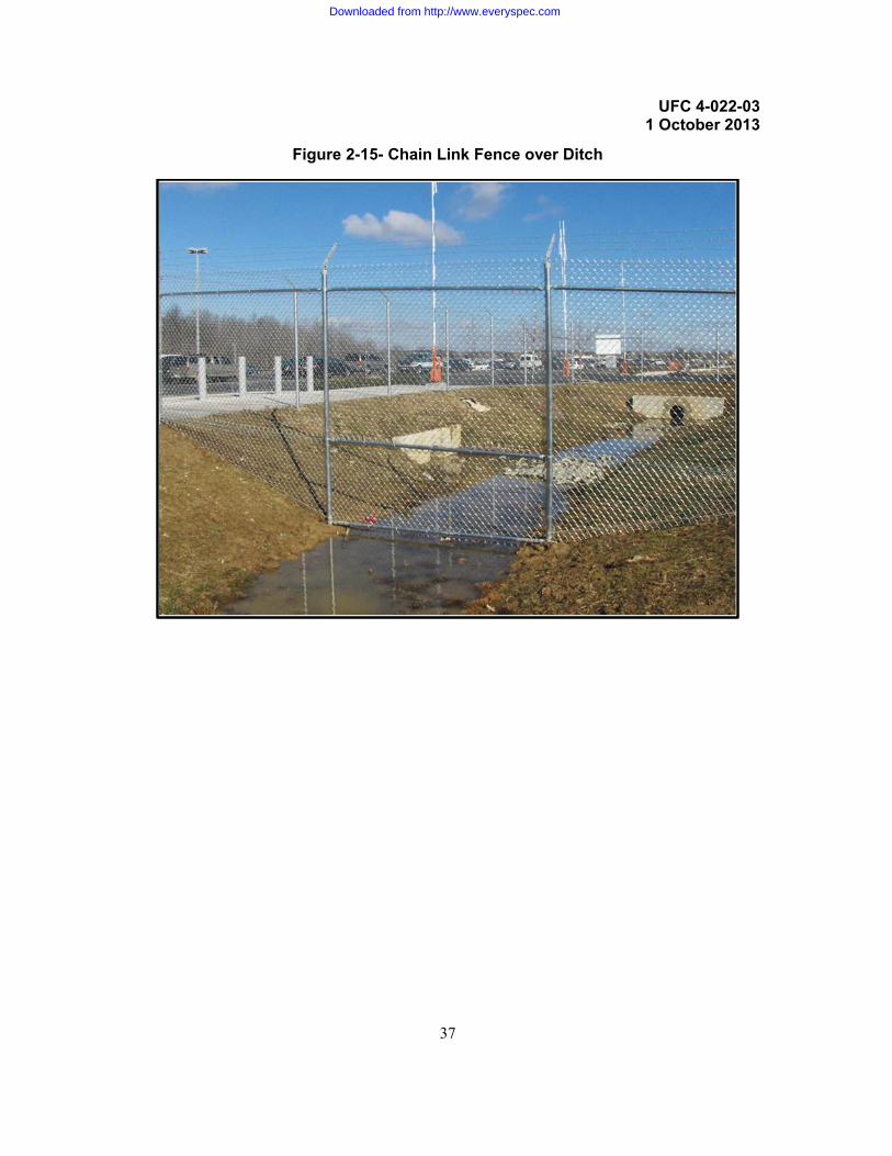
Fencing passing over ditches or swales is intended to provide protection to prevent unauthorized entry. Ditches and swales that do not receive frequent water flow must provide additional fencing below, suspending from the lower rail of the main fence to the auxiliary frame and around the sides of the ditch. See Figure 2-15. The added fence must be attached every 2 inches (51 mm) along the intersection of the two fence sections and either attached to a series of ground stakes secured to the sides and bottom of the ditch, or embedded in a concrete sill in the ditch or swale as shown in Figures 2-12 and 2-13. Concrete curbing must be used to fill areas between fencing and ground surface.
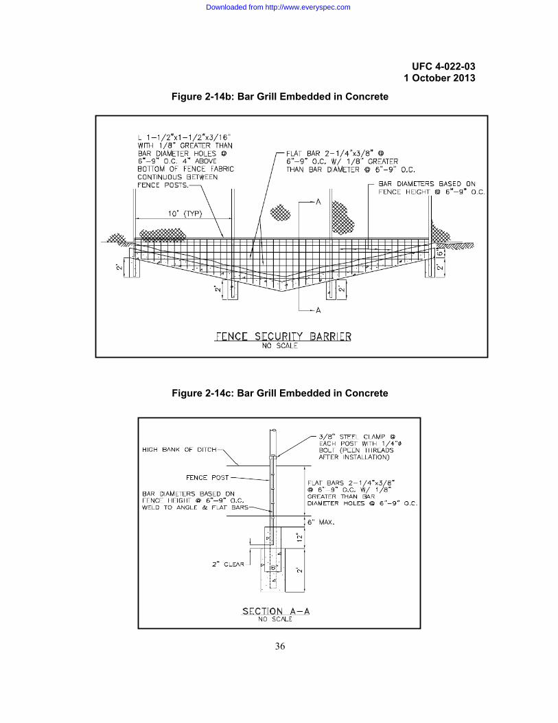
Provide a screen arrangement below fencing using vertical and/or horizontal steel bars or pipes for ditches and swales receiving frequent water flow. Provide a maximum spacing of 9 inches (229 mm) between either vertical or horizontal bars. Possible debris must be considered when designing the spacing between bars. Crossing bars must be welded at each intersection, with bars embedded 6 inches (152 mm) into concrete and fastened to the bottom rail of the crossing fence. See Figures 2-14a/b/c/. Analyze the hydraulic capacity of ditches, swales, and culverts to verify the bar grills will not decrease the channel flow capacity below the maximum expected design flow.
Downloaded from http://www.everyspec.com
UFC 4-022-03 1 October 2013
34
Steel used for grill must be in accordance with ASTM A529 and the corrosion prevention control section of this UFC.
2-12.8 Tunneling Prevention
Soil under fence must provide a minimum of 15 seconds of tunneling resistance using hand tools. Tunneling prevention must be used in areas containing “soft” soils. UFC 3-220-10N describes “very soft” and “soft” soils as those that can be extruded between fingers when squeezed and/or molded by light finger pressure. Classification of soils must be in accordance with ASTM D2487, Standard Practice for Classification of Soils for Engineering Purposes (Unified Soil Classification System), and ASTM D2488, Standard Practice for Description and Identification of Soils (Visual-Manual Procedure). Areas with a soil analysis indicating that “soft” soils are present must embed fencing in a continuous concrete curb. The recommended depth of the curb will be determined from the soil analysis and the frost depth at the facility. The frost depth for the subject areas must be considered to assure that heaving of posts and curb cannot occur during the winter. If the soil analysis does not indicate tunneling may occur quickly, continuous concrete curbing may still be considered as an added protective measure. Nuclear sites with very sandy terrain are directed to have a soils engineering analysis to determine the recommended depth of the concrete curb. Restricted access facilities with a risk of tunneling may provide IDS for tunneling protection. Welded wire mesh fence systems may incorporate additional fence panels for burial on the secure-side of the perimeter and tie-wired to the vertical panels to deter tunneling.
Figure 2-12: Swale Crossing with Ground Stakes
Downloaded from http://www.everyspec.com
UFC 4-022-03 1 October 2013
35
Figure 2-13: Swale Crossing Embedded in Concrete
Figure 2-14a: Bar Grill Embedded in Concrete
Downloaded from http://www.everyspec.com
UFC 4-022-03 1 October 2013
36
Figure 2-14b: Bar Grill Embedded in Concrete
Figure 2-14c: Bar Grill Embedded in Concrete
Downloaded from http://www.everyspec.com
UFC 4-022-03 1 October 2013
37
Figure 2-15- Chain Link Fence over Ditch
Downloaded from http://www.everyspec.com

UFC 4-022-03 1 October 2013
38
This Page Intentionally Left Blank
Downloaded from http://www.everyspec.com
UFC 4-022-03 1 October 2013
39
CHAPTER 3 GATES
3-1 GATES OVERVIEW
3-1.1 Access Control
Access Control is a primary design consideration for gate systems. The design of gates must consider and address the following items to ensure proper specification of power-operator accessories and controls. See Appendix C for details of standard gates.
x Pedestrian traffic
x Reversing devices to keep gates from closing on vehicles
x Traffic flow
x Number of open and close cycles
x Type of vehicles
x Operational site security plan
x Provide lighting in accordance with UFC 3-530-01, Design: Interior and Exterior Lighting and Controls.
Gates, as part of perimeter fences, must be as effective as their associated fence to provide an equivalent deterrent. Gates will normally require additional hardening features due to their location across entrance roads and the inherent vulnerability of their hinges and latches. Gates are known to be the weakest point in the perimeter security fence and as such, attention must be paid to their requirements when designing security fencing. Materials used in fabricating and erecting chain-link gates must be the same as the materials used for the associated chain-link fence. A primary concern for gate design associated with security fences is to assure that the bottom of the gate fabric extends within 2 inches (51mm) of the roadbed or firm soil when closed. Where possible, pedestrian and vehicular gates should be clearly separated and defined.
3-2 PERSONNEL GATES
Personnel gates are intended to be designed to permit only one person to approach the guard at any time. Turnstile gates may be considered to control personnel entry.
Gates must conform to the Architectural Barrier Act (ABA) Accessibility Standard for Department of Defense Facilities as adopted by the Deputy Secretary of Defense memorandum dated October 31, 2008.
3-2.1 Single Swing Gates
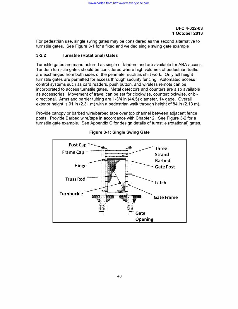
Design single swing gates to match fence fabric height, with an additional 1 ft (305 mm) of three strand barbed wire added to the height if barb wire is part of the fence structure. The gate opening should not exceed a width of 14 ft (4.3 m). See ASTM F900 for additional gate requirements.
Downloaded from http://www.everyspec.com
UFC 4-022-03 1 October 2013
40
For pedestrian use, single swing gates may be considered as the second alternative to turnstile gates. See Figure 3-1 for a fixed and welded single swing gate example
3-2.2 Turnstile (Rotational) Gates
Turnstile gates are manufactured as single or tandem and are available for ABA access. Tandem turnstile gates should be considered where high volumes of pedestrian traffic are exchanged from both sides of the perimeter such as shift work. Only full height turnstile gates are permitted for access through security fencing. Automated access control systems such as card readers, push button, and wireless remote can be incorporated to access turnstile gates. Metal detectors and counters are also available as accessories. Movement of travel can be set for clockwise, counterclockwise, or bi-directional. Arms and barrier tubing are 1-3/4 in (44.5) diameter, 14 gage. Overall exterior height is 91 in (2.31 m) with a pedestrian walk through height of 84 in (2.13 m).
Provide canopy or barbed wire/barbed tape over top channel between adjacent fence posts. Provide Barbed wire/tape in accordance with Chapter 2. See Figure 3-2 for a turnstile gate example. See Appendix C for design details of turnstile (rotational) gates.
Figure 3-1: Single Swing Gate
Downloaded from http://www.everyspec.com

UFC 4-022-03 1 October 2013
41
Figure 3-2: Turnstile/Turnstile with Barbed Wire
3-3 VEHICULAR GATES
Vehicular gates should limit opening sizes when possible to decrease open/close cycle time. There is no maximum height for vehicular gates. Coordinate gate height with surrounding/adjacent security fencing and the width will be at least as wide as the road entering the gate. The operational requirements for the gate must be evaluated to determine which gate type is most suitable. Analysis for all vehicular gates must consider daily peak of vehicular traffic and the operational access control requirements for the secured area to determine opening size, gate type, and whether an automatic operator is needed. Follow the requirements of ASTM F2200 for gates used for vehicular traffic that are to be automated. Cantilevered, sliding or wheel supported gates are considered the best selection for vehicle security gates followed by overhead sliding gates, swing gates, vertical tilt and overhead “guillotine” gates. Areas where snow and ice are prevalent may consider using cantilever or swing gates instead of tracked sliding gates. However, if sliding gates are used, consideration should be given to adding internal heating for gate mechanisms. Areas where real estate is tight vertical tilt gates are recommended.
3-3.1 Sliding Gates
Sliding gates must have all entry-exit points secured with a heavy duty sliding steel, iron, or heavily braced chain link gate equipped with a heavy locking device. The cross-slope of the road surface must be sloped at a constant grade for the full length of the
Downloaded from http://www.everyspec.com
UFC 4-022-03 1 October 2013
42
gate path to permit proper drainage while maintaining smooth operation of the gate opening and closing. Where a sliding gate is installed at an existing paved entrance, the pavement may be filled or leveled where the gate will be installed. Follow the requirement of ASTM F1184 for sliding gates.
3-3.1.1 Single Wheel-Supported (V-groove) Sliding Gate
A guide rail or trough across the roadbed is utilized by this type of gate. The trough provides a smoother surface for vehicular traffic, but is not recommended due to debris buildup. Single wheel supported sliding gates do not have an opening distance restriction, but are limited by the power requirements of the gate operator. Wheel supported gates require 1/3 less straight level storage space along adjacent fence than cantilevered.
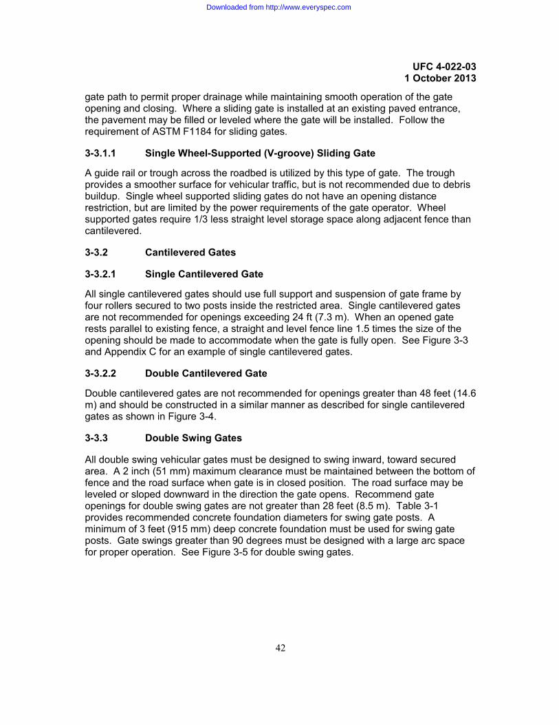
3-3.2 Cantilevered Gates
3-3.2.1 Single Cantilevered Gate
All single cantilevered gates should use full support and suspension of gate frame by four rollers secured to two posts inside the restricted area. Single cantilevered gates are not recommended for openings exceeding 24 ft (7.3 m). When an opened gate rests parallel to existing fence, a straight and level fence line 1.5 times the size of the opening should be made to accommodate when the gate is fully open. See Figure 3-3 and Appendix C for an example of single cantilevered gates.
3-3.2.2 Double Cantilevered Gate
Double cantilevered gates are not recommended for openings greater than 48 feet (14.6 m) and should be constructed in a similar manner as described for single cantilevered gates as shown in Figure 3-4.
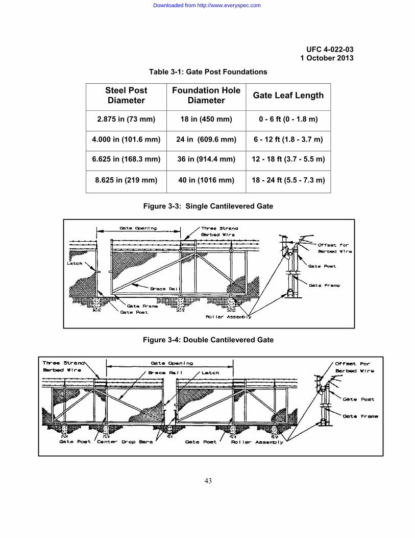
3-3.3 Double Swing Gates
All double swing vehicular gates must be designed to swing inward, toward secured area. A 2 inch (51 mm) maximum clearance must be maintained between the bottom of fence and the road surface when gate is in closed position. The road surface may be leveled or sloped downward in the direction the gate opens. Recommend gate openings for double swing gates are not greater than 28 feet (8.5 m). Table 3-1 provides recommended concrete foundation diameters for swing gate posts. A minimum of 3 feet (915 mm) deep concrete foundation must be used for swing gate posts. Gate swings greater than 90 degrees must be designed with a large arc space for proper operation. See Figure 3-5 for double swing gates.
Downloaded from http://www.everyspec.com
UFC 4-022-03 1 October 2013
43
Table 3-1: Gate Post Foundations
Steel Post Diameter
Foundation Hole Diameter Gate Leaf Length
2.875 in (73 mm) 18 in (450 mm) 0 - 6 ft (0 - 1.8 m)
4.000 in (101.6 mm) 24 in (609.6 mm) 6 - 12 ft (1.8 - 3.7 m)
6.625 in (168.3 mm) 36 in (914.4 mm) 12 - 18 ft (3.7 - 5.5 m)
8.625 in (219 mm) 40 in (1016 mm) 18 - 24 ft (5.5 - 7.3 m)
Figure 3-3: Single Cantilevered Gate
Figure 3-4: Double Cantilevered Gate
Downloaded from http://www.everyspec.com
UFC 4-022-03 1 October 2013
44
Figure 3-5: Double Swing Gate
3-3.4 Vertical Pivot Gate
Vertical pivot gates can be manufactured with chain link fabric, expanded metal, ornamental, or similar materials as indicated within this document. A 2 inch (51 mm) maximum clearance must be maintained between the bottom of fence and the road surface when gate is in closed position. Recommend gate openings are not greater than 24 feet (7.3 m). For openings greater than 24 feet (7.3 m), consult with the manufacturer. See specific manufacturer requirements for gate foundation.
3-3.5 Overhead (Sliding) Gates
An overhead gate is a horizontal slide gate supported by an I-beam or enclosed track that is suspended above the opening. The support must extend at least the full opening width on one side of the opening to support storing the gate parallel to the adjacent fence line when the gate is opened. The gate storage area must be in line with the gate opening and either be level or have a decreasing grade to accommodate the gate when it is fully opened. Gates may be suspended from the I-beam or enclosed track by rollers attached to posts extending upward from the leading and trailing edge of the gate. The overhead beam or track height is intended to allow room for the largest possible vehicle going through the gate. Gates should be suspended above ground from the overhead beam or track and supported laterally near the ground by vertical rollers. The I-beam may be applied to strengthen the gate for peak hour traffic, large opening sizes, and heavy gate construction. More posts extending upward from the center of the gate to the tracks may be added to carry heavier loads. Overhead gates must conform to ASTM F1184.
3-3.4.1 Single Overhead Supported Gate
See Appendix C for design details of single overhead supported gates.
Downloaded from http://www.everyspec.com
UFC 4-022-03 1 October 2013
45
3-3.4.2 Double Overhead Supported Gate (Biparting) Gate
See Appendix C for design details of double overhead supported gates.
3-3.6 Vertical Lift Gate
The vertical lift gate, or “guillotine” gate, should be used where the topography does not provide enough room to store the gate adjacent to the fence line. Vertical lift gates should have a counterweight with a continuous drive chain on each side.
3-4 GATE REINFORCEMENT
The gates discussed under the ‘Vehicular Gates’ paragraph above are non-reinforced gates and not considered to resist impact by vehicles. Standard non-reinforced gates can be fitted with cables, chains, and anchors to increase their resistance to penetration by vehicles. In addition, there are proprietary, rated active vehicle barrier gate systems that are designed to resist penetration by vehicles. See UFC 4-022-02 for additional information on active and passive vehicle barriers. Provide cables at a minimum 3/4 inch (19 mm) wire rope in accordance with ASTM A1023/A1023M. Welded alloy steel chains must be minimum 1/2 inch (13 mm) diameter. These wire ropes must then be chained together and fastened with padlocks to create a continuous barrier. Padlocks used with this system must be medium security padlocks. The wire ropes must be positioned as to not interfere with gate operations when the chain is removed. Figures 3-6 through 3-8 and details in the drawings of Appendix C provide illustrations for reinforced gates.
Application of deadman anchors must be in accordance with the provisions of Chapter 2. See Appendix C for additional reinforcement details for gates.
3-4.1 Swing Gates
For swing gates, the cable must be looped around the gatepost, the gate frame upright, and through the fence cable loop. Cable must be strung across the inside of the gate leaf and fastened around the vertical gate frame upright and fabric tension bar midway above the road surface. The cable must be terminated with a swaged loop or wire rope clamp around the gatepost to interconnect with the gate cable barrier system. All cable ends must be looped and terminated with either four wire rope clamps or hydraulically swaged wire rope fittings. Remove sheathing on covered cables at connections so that the connections can be properly made and rated.
Downloaded from http://www.everyspec.com

UFC 4-022-03 1 October 2013
46
Figure 3-6: Locking Assembly for Reinforced Swing Gate
Figure 3-7: Locking Assembly for Reinforced Sliding Gate
Downloaded from http://www.everyspec.com
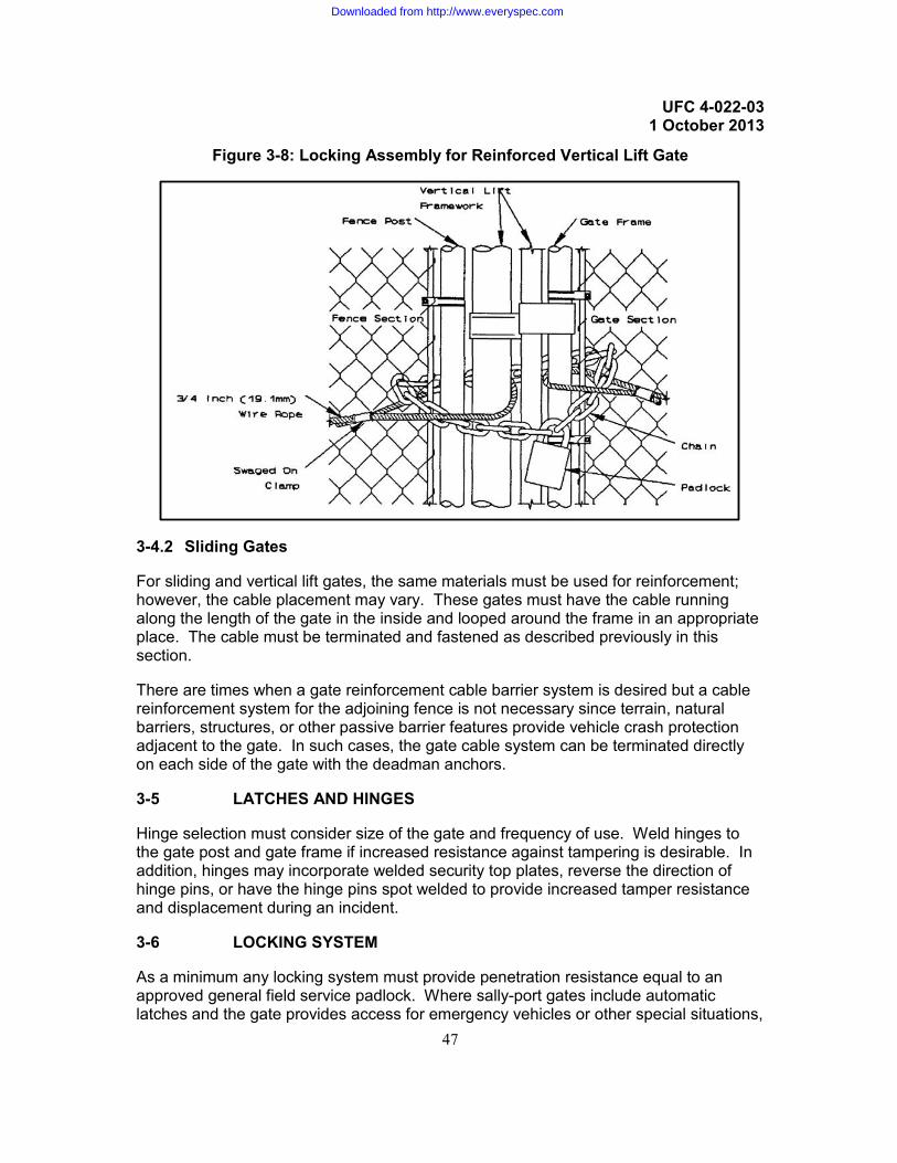
UFC 4-022-03 1 October 2013
47
Figure 3-8: Locking Assembly for Reinforced Vertical Lift Gate
3-4.2 Sliding Gates
For sliding and vertical lift gates, the same materials must be used for reinforcement; however, the cable placement may vary. These gates must have the cable running along the length of the gate in the inside and looped around the frame in an appropriate place. The cable must be terminated and fastened as described previously in this section.
There are times when a gate reinforcement cable barrier system is desired but a cable reinforcement system for the adjoining fence is not necessary since terrain, natural barriers, structures, or other passive barrier features provide vehicle crash protection adjacent to the gate. In such cases, the gate cable system can be terminated directly on each side of the gate with the deadman anchors.
3-5 LATCHES AND HINGES
Hinge selection must consider size of the gate and frequency of use. Weld hinges to the gate post and gate frame if increased resistance against tampering is desirable. In addition, hinges may incorporate welded security top plates, reverse the direction of hinge pins, or have the hinge pins spot welded to provide increased tamper resistance and displacement during an incident.
3-6 LOCKING SYSTEM
As a minimum any locking system must provide penetration resistance equal to an approved general field service padlock. Where sally-port gates include automatic latches and the gate provides access for emergency vehicles or other special situations,
Downloaded from http://www.everyspec.com
UFC 4-022-03 1 October 2013
48
the gatehouse must have an emergency override. The padlocked bolt or plunger arrangement must not be easily accessible from outside the barrier. Padlocks used must be medium security padlocks.
See Appendix C for design details of chain and wire rope locking systems.
3-7 GATE POWER OPERATORS
Locate all gate operators to prevent tampering from outside the fence. Coordinate design of gate operating systems with the Command Safety Officer to ensure consideration of site particular operating accessories, warning devices, and safety systems. Coordinate gate operation safety with guidance provided in UFC 4-022-01, Security Engineering: Entry Control Facilities/Access Control Points.
Provide powered gate operators for vertical lift gates unless use is infrequent and manual operation is reasonable. Powered gate operators with automatic latching systems must be provided at nuclear storage facilities.
3-7.1 Sliding Gate Power Operators
Automated sliding gates at restricted areas should use positive drive rail gate power-operators.
3-7.2 Swing Gate Power Operators
Swing gate power operators may be either positive drive or electromechanical swing.
3-7.3 Linear Induction Gate Operators
A linear induction gate operator incorporates electromagnetic Linear Induction Motor (LIM) technology, eliminating moving drive components, hydraulic fluids and lubricants and their environmental risks. This technology combines unprecedented speed and reliability and without moving drive components, making it efficient in operation and less costly to maintain. This technology is compatible with existing access control devices and can be specified for new construction or easily retro-fitted to accommodate existing gates. No requirement for any connecting mechanisms such as chains, gear boxes, or belts. Can work in the most rugged environment and has flexible settings that allow for variable and differentiate speeds for open and close mode. LIM technology can reach gate operating speeds of up to 8 feet (2.44m) per second – a significant improvement over existing designs that operate at approximately 1 foot (0.305 meter) per second.
Downloaded from http://www.everyspec.com
UFC 4-022-03 1 October 2013
49
APPENDIX A REFERENCES
DEPARTMENT OF THE AIR FORCE
http://www.e-publishing.af.mil/
AFI 31-101, Integrated Defense (FOUO)
AFMAN 31-108, The Air Force Nuclear Security Manual (FOUO)
AFMAN 32-1084, Civil Engineering: Facility Requirements
DEPARTMENT OF ARMY
http://armypubs.army.mil/index.html
AR 190-11, Physical Security of Arms, Ammunition, and Explosives
AR 190-13, The Army Physical Security Program
AR 190-16, Physical Security
AR 190–54, Security of Nuclear Reactors and Special Nuclear Materials
ATTP 3-39.32, Physical Security
ASTM: SEE REFERENCE TABLE BELOW
http://www.astm.org/
CHAIN LINK FENCE MANUFACTURERS INSTITUTE
http://www.associationsites.com/main-pub.cfm?usr=clfma
CLF-SFR0111, Security Fencing Recommendations
CLF-PM0610, Product Manual
DEPARTMENT OF DEFENSE
http://www.dtic.mil/whs/directives/
DoD I 2000.12, DoD Antiterrorism Program
DoD I 2000.16, DoD Antiterrorism Standards
DoD O-2000.12H, DoD Antiterrorism Handbook
DoD 5100.76-M, Physical Security of Sensitive Conventional Arms, Ammunition, and Explosives
Downloaded from http://www.everyspec.com
UFC 4-022-03 1 October 2013
50
DoD 5200.08-R, Physical Security Program
DoD S-5210.41-M, Volumes 1-3, Nuclear Weapons Security Manual: The DoD Nuclear Weapon Security Program (FOUO)
GTA 90-01-011, Joint Forward Operations Base (JFOB) Survivability and Protective Construction Handbook- (For Official Use Only [FOUO])
DEPARTMENT OF DEFENSE, UNIFIED FACILITIES PROGRAM
http://dod.wbdg.org/
UFC 1-200-01, General Building Requirements
UFC 3-220-10N, Soil Mechanics
UFC 3-260-01, Airfield and Heliport Planning and Design
UFC 3-530-01, Design: Interior and Exterior Lighting and Controls
UFC 3-600-01, Fire Protection Engineering for Facilities
UFC 4-010-01, DoD Minimum Antiterrorism Standards for Buildings
UFC 4-020-01, DoD Security Engineering Facilities Planning Manual
UFC 4-020-02, DoD Security Engineering Facilities Design Manual (Draft)
UFC 4-021-02, Electronic Security Systems
UFC 4-022-01, Security Engineering: Entry Control Facilities/Access Control Points
UFC 4-022-02, Security Engineering: Design and Selection of Vehicle Barriers
UFC 4-141-10N, Design: Aviation Operation and Support Facilities
UFGS 32 31 13.53, High-Security Chain Link Fences and Gates
UFGS 32 31 13, Chain Link Fences and Gates
UFGS 32 31 26, Wire Fences and Gates
IEEE
http://www.ieeeusa.org/
IEEE C2, National Electric Safety Code
IEEE Std 80™-2000, IEEE Guide for Safety in AC Substation Grounding
Downloaded from http://www.everyspec.com
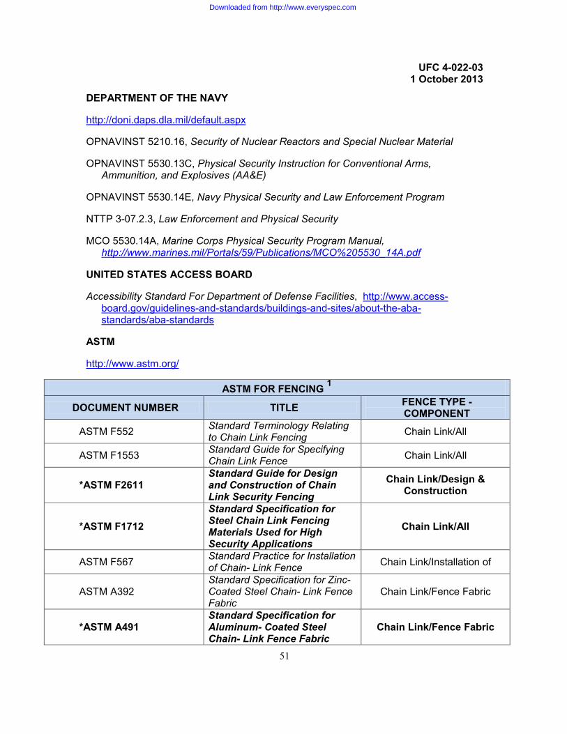
UFC 4-022-03 1 October 2013
51
DEPARTMENT OF THE NAVY
http://doni.daps.dla.mil/default.aspx
OPNAVINST 5210.16, Security of Nuclear Reactors and Special Nuclear Material
OPNAVINST 5530.13C, Physical Security Instruction for Conventional Arms, Ammunition, and Explosives (AA&E)
OPNAVINST 5530.14E, Navy Physical Security and Law Enforcement Program
NTTP 3-07.2.3, Law Enforcement and Physical Security
MCO 5530.14A, Marine Corps Physical Security Program Manual, http://www.marines.mil/Portals/59/Publications/MCO%205530_14A.pdf
UNITED STATES ACCESS BOARD
Accessibility Standard For Department of Defense Facilities, http://www.access-board.gov/guidelines-and-standards/buildings-and-sites/about-the-aba-standards/aba-standards
ASTM
http://www.astm.org/
ASTM FOR FENCING 1
DOCUMENT NUMBER TITLE FENCE TYPE - COMPONENT
ASTM F552 Standard Terminology Relating to Chain Link Fencing Chain Link/All
ASTM F1553 Standard Guide for Specifying Chain Link Fence Chain Link/All
*ASTM F2611 Standard Guide for Design and Construction of Chain Link Security Fencing
Chain Link/Design & Construction
*ASTM F1712 Standard Specification for Steel Chain Link Fencing Materials Used for High Security Applications
Chain Link/All
ASTM F567 Standard Practice for Installation of Chain- Link Fence Chain Link/Installation of
ASTM A392 Standard Specification for Zinc- Coated Steel Chain- Link Fence Fabric
Chain Link/Fence Fabric
*ASTM A491 Standard Specification for Aluminum- Coated Steel Chain- Link Fence Fabric
Chain Link/Fence Fabric
Downloaded from http://www.everyspec.com
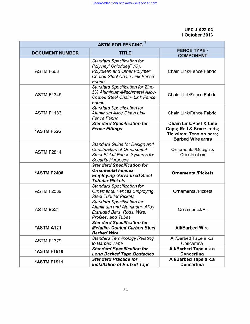
UFC 4-022-03 1 October 2013
52
ASTM FOR FENCING 1
DOCUMENT NUMBER TITLE FENCE TYPE - COMPONENT
ASTM F668
Standard Specification for Polyvinyl Chloride(PVC), Polyolefin and Other Polymer Coated Steel Chain Link Fence Fabric
Chain Link/Fence Fabric
ASTM F1345
Standard Specification for Zinc-5% Aluminum-Mischmetal Alloy-Coated Steel Chain- Link Fence Fabric
Chain Link/Fence Fabric
ASTM F1183 Standard Specification for Aluminum Alloy Chain Link Fence Fabric
Chain Link/Fence Fabric
*ASTM F626 Standard Specification for Fence Fittings
Chain Link/Post & Line Caps; Rail & Brace ends; Tie wires; Tension bars;
Barbed Wire arms
ASTM F2814
Standard Guide for Design and Construction of Ornamental Steel Picket Fence Systems for Security Purposes
Ornamental/Design & Construction
*ASTM F2408 Standard Specification for Ornamental Fences Employing Galvanized Steel Tubular Pickets
Ornamental/Pickets
ASTM F2589 Standard Specification for Ornamental Fences Employing Steel Tubular Pickets
Ornamental/Pickets
ASTM B221
Standard Specification for Aluminum and Aluminum- Alloy Extruded Bars, Rods, Wire, Profiles, and Tubes
Ornamental/All
*ASTM A121 Standard Specification for Metallic- Coated Carbon Steel Barbed Wire
All/Barbed Wire
ASTM F1379 Standard Terminology Relating to Barbed Tape
All/Barbed Tape a.k.a Concertina
*ASTM F1910 Standard Specification for Long Barbed Tape Obstacles
All/Barbed Tape a.k.a Concertina
*ASTM F1911 Standard Practice for Installation of Barbed Tape
All/Barbed Tape a.k.a Concertina
Downloaded from http://www.everyspec.com
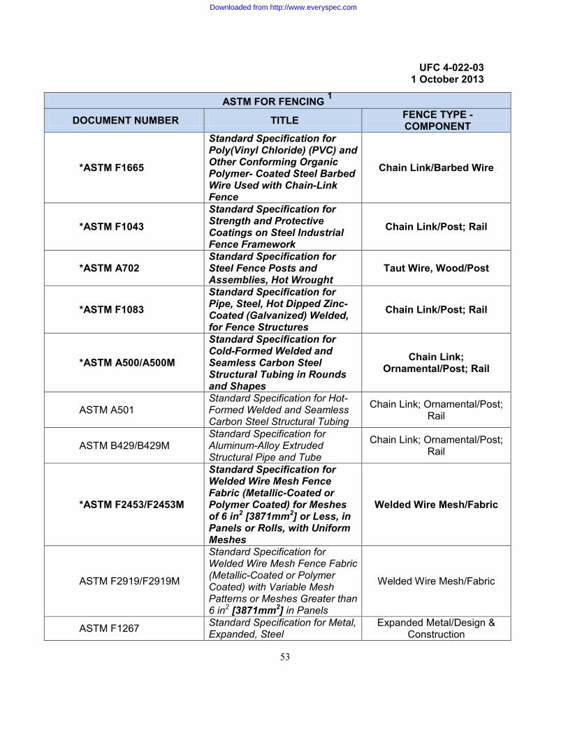
UFC 4-022-03 1 October 2013
53
ASTM FOR FENCING 1
DOCUMENT NUMBER TITLE FENCE TYPE - COMPONENT
*ASTM F1665
Standard Specification for Poly(Vinyl Chloride) (PVC) and Other Conforming Organic Polymer- Coated Steel Barbed Wire Used with Chain-Link Fence
Chain Link/Barbed Wire
*ASTM F1043 Standard Specification for Strength and Protective Coatings on Steel Industrial Fence Framework
Chain Link/Post; Rail
*ASTM A702 Standard Specification for Steel Fence Posts and Assemblies, Hot Wrought
Taut Wire, Wood/Post
*ASTM F1083 Standard Specification for Pipe, Steel, Hot Dipped Zinc- Coated (Galvanized) Welded, for Fence Structures
Chain Link/Post; Rail
*ASTM A500/A500M
Standard Specification for Cold-Formed Welded and Seamless Carbon Steel Structural Tubing in Rounds and Shapes
Chain Link; Ornamental/Post; Rail
ASTM A501 Standard Specification for Hot- Formed Welded and Seamless Carbon Steel Structural Tubing
Chain Link; Ornamental/Post; Rail
ASTM B429/B429M Standard Specification for Aluminum-Alloy Extruded Structural Pipe and Tube
Chain Link; Ornamental/Post; Rail
*ASTM F2453/F2453M
Standard Specification for Welded Wire Mesh Fence Fabric (Metallic-Coated or Polymer Coated) for Meshes of 6 in2 [3871mm2] or Less, in Panels or Rolls, with Uniform Meshes
Welded Wire Mesh/Fabric
ASTM F2919/F2919M
Standard Specification for Welded Wire Mesh Fence Fabric (Metallic-Coated or Polymer Coated) with Variable Mesh Patterns or Meshes Greater than 6 in2 [3871mm2] in Panels
Welded Wire Mesh/Fabric
ASTM F1267 Standard Specification for Metal, Expanded, Steel
Expanded Metal/Design & Construction
Downloaded from http://www.everyspec.com
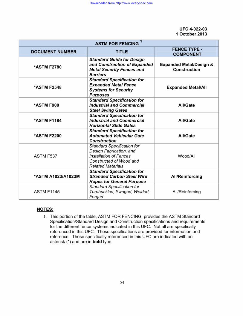
UFC 4-022-03 1 October 2013
54
ASTM FOR FENCING 1
DOCUMENT NUMBER TITLE FENCE TYPE - COMPONENT
*ASTM F2780 Standard Guide for Design and Construction of Expanded Metal Security Fences and Barriers
Expanded Metal/Design & Construction
*ASTM F2548 Standard Specification for Expanded Metal Fence Systems for Security Purposes
Expanded Metal/All
*ASTM F900 Standard Specification for Industrial and Commercial Steel Swing Gates
All/Gate
*ASTM F1184 Standard Specification for Industrial and Commercial Horizontal Slide Gates
All/Gate
*ASTM F2200 Standard Specification for Automated Vehicular Gate Construction
All/Gate
ASTM F537
Standard Specification for Design Fabrication, and Installation of Fences Constructed of Wood and Related Materials
Wood/All
*ASTM A1023/A1023M Standard Specification for Stranded Carbon Steel Wire Ropes for General Purpose
All/Reinforcing
ASTM F1145 Standard Specification for Turnbuckles, Swaged, Welded, Forged
All/Reinforcing
NOTES:
1. This portion of the table, ASTM FOR FENCING, provides the ASTM Standard Specification/Standard Design and Construction specifications and requirements for the different fence systems indicated in this UFC. Not all are specifically referenced in this UFC. These specifications are provided for information and reference. Those specifically referenced in this UFC are indicated with an asterisk (*) and are in bold type.
Downloaded from http://www.everyspec.com
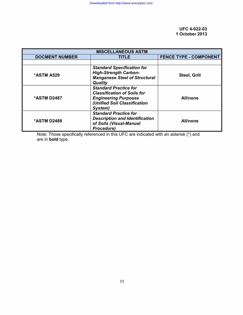
UFC 4-022-03 1 October 2013
55
Note: Those specifically referenced in this UFC are indicated with an asterisk (*) and are in bold type.
MISCELLANEOUS ASTM DOCMENT NUMBER TITLE FENCE TYPE - COMPONENT
*ASTM A529 Standard Specification for High-Strength Carbon-Manganese Steel of Structural Quality
Steel, Grill
*ASTM D2487
Standard Practice for Classification of Soils for Engineering Purposes (Unified Soil Classification System)
All/none
*ASTM D2488 Standard Practice for Description and Identification of Soils (Visual-Manual Procedure)
All/none
Downloaded from http://www.everyspec.com

UFC 4-022-03 1 October 2013
56
This Page Left Intentionally Blank
Downloaded from http://www.everyspec.com
UFC 4-022-03 1 October 2013
57
APPENDIX B GLOSSARY
B-1 DEFINITION OF TERMS
Active Sensors: A sensor that can receive signals from either itself or other devices.
Attack Side: The outer side of the perimeter fence for a protected area. The side from which to expect attacks or forced entry.
Bollards: Reinforced concrete shapes or sleeves, or steel pipe filled with concrete, used to slow down vehicles and/or deny vehicle access.
Clear Zone: Area free of obstacles, topographical features and vegetation which reduce the effectiveness of the physical barrier, impede observation or provide cover and concealment of an intruder.
Color Polymer Coating: A coating on chain link fences to further protect and add color.
Concrete Sill or Curb: A concrete section to create a non-passable connection between a fence and the existing ground.
Corrosive or Salt Laden Environment/Atmosphere: Atmosphere which contains enough salt or corrosive elements to corrode a fence enough to decrease the intended strength. These areas are typically bordering oceans or other water bodies. For the application of coating requirements in this UFC, the corrosive atmosphere is considered 10 miles (16 kilometers) from coastal mean high water line.
Deadman Anchor : An anchor for fence or gate reinforcement cables which transfer the force from the fencing or gate fabric/surface to the ground. Deadman anchors are typically concrete blocks buried in the ground.
Electronic Security System (ESS): The integrated electronic system that encompasses interior and exterior Intrusion Detection Systems (IDS), Closed Circuit Television (CCTV) systems for assessment of alarm conditions, Automated Access Control Systems (ACS), Data Transmission Media (DTM) and alarm reporting systems for monitoring, control and display.
Eye Ends: Center space created when looping a wire for termination or reinforcement.
Fabric Diamonds: The opening formed by the woven wires in chain link fence fabric.
Fabric Tension Bar: A bar that the fencing fabric is attached to and it serves to hold the fabric tight to decrease ability to deform.
Downloaded from http://www.everyspec.com
UFC 4-022-03 1 October 2013
58
Fencing Accessories: Any fasteners, ties, wires or other objects used to attaching the fencing fabric, posts or top guards.
Fence Fabric : As used in this document means (chain link, ornamental, welded wire mesh, expanded metal).
Gate Leaf: A panel of a gate (There is one gate leaf for single fences and two for double fences).
Gates Openings: In the barrier system to allow authorized entry and exit.
Intrusion Detection System (IDS): A system consisting of interior and exterior sensors, surveillance devices, and associated communication subsystems that collectively detect an intrusion of a specified site, facility or perimeter and annunciate an alarm.
Line Posts: intermediate posts spaced a maximum of 10 feet (3 m) apart and considered the backbone of the fence line.
Mesh Openings: The opening formed by the woven wires.
Moving Vehicle Bomb Tactic: A forced entry tactic to place an explosive or other damaging terrorist device in a moving vehicle to create a mobile vehicular weapon.
Natural Boundaries: Natural formations such as bodies of water, rough terrain, or densely wooded areas that may act as a barrier to define and protect the restricted area's perimeter.
Outriggers: Metal top guards which are placed on the top of the barrier and may consist of at least one vertical arm, angled arm facing inside, angles arm facing outside or two angles arms facing both inside and outside. In addition, there may be more than one arm on each side if desired. The number and direction of arms depends on the nature of the barrier.
Passive Barriers: A passive barrier has no moving parts. Passive barrier effectiveness relies on its ability to absorb energy and transmit the energy to its foundation. Highway medians (Jersey), bollards or posts, tires, guardrails, ditches and reinforced fences are examples of passive barriers.
Passive Sensors: A sensor that receives signals through light or radio waves.
Protected Side: The inside of the fence that is being protected through various security measures.
Sally Ports: Sally ports are used to control entry into highly protected and restricted areas and used as part of an entry control facility/access control point for vehicle inspection.
Downloaded from http://www.everyspec.com
UFC 4-022-03 1 October 2013
59
Secure Side: The inside of the fence that is being protected through various security measures.
Special Nuclear Material (SNM): Nuclear material that requires extensive protection.
Swaged Loop: A loop created by looping a wire and fastening the loop with a swaged on clamp.
Swing Gates: Gates for entrance or exit that swing open either manually or automatically when controlled either electronically or manually.
Taut Wire: Wire that is continuously under tension through a series of spring connections.
Tension Bar: The bar that is threaded through the last vertical link of fabric. It attaches the fabric to the terminal post.
Top Guard: Additional protection of fences or other barriers that are placed on top of the barrier to prevent climbing or jumping. Possible top guards include, but are not limited to, outriggers with barbed wire, concertina wire, or barbed tape.
Truss Rods: A rod used in brace assemblies to draw and hold the line post firmly to the brace rail. The truss rod uses an adjustable turnbuckle to maintain proper tension. Truss rod details can be seen in the "Non Reinforced Chain-Link Fence" drawings in Appendix C.
Turnbuckles: A metal coupling device consisting of an oblong piece internally threaded at both ends into which the corresponding sections of two threaded rods are screwed in order to form a unit that can be adjusted for tension or length.
Turnstile Gates: Pedestrian gates which rotate around a central pole to allow only one entrance at a time.
Welded Bar Grill: A series of vertical and horizontal bars that are placed over an opening and welded at all bar crossing points.
Additional Terms relating to fences are found in:
x ASTM F552 - Standard Terminology Relating to Chain Link Fencing
x ASTM F2814 - Standard Guide for Design and Construction of Ornamental Steel Picket Fence Systems for Security Purposes
x ASTM F2780 - Standard Guide for Design and Construction of Expanded Metal Security Fences and Barriers
x ASTM F1379 - Standard Terminology Relating to Barbed Tape
Downloaded from http://www.everyspec.com
UFC 4-022-03 1 October 2013
60
x ASTM F537 - Standard Specification for Design, Fabrication, and Installation of Fences Constructed of Wood and Related Materials
Downloaded from http://www.everyspec.com
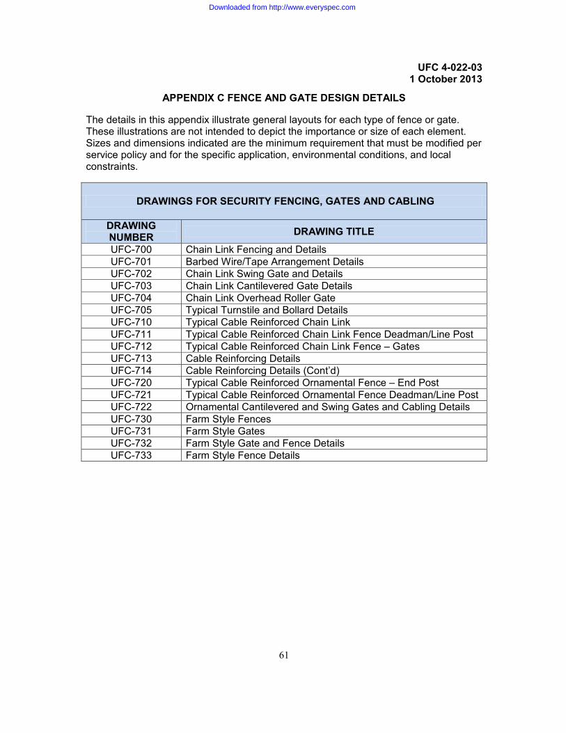
UFC 4-022-03 1 October 2013
61
APPENDIX C FENCE AND GATE DESIGN DETAILS
The details in this appendix illustrate general layouts for each type of fence or gate. These illustrations are not intended to depict the importance or size of each element. Sizes and dimensions indicated are the minimum requirement that must be modified per service policy and for the specific application, environmental conditions, and local constraints.
DRAWINGS FOR SECURITY FENCING, GATES AND CABLING
DRAWING NUMBER DRAWING TITLE
UFC-700 Chain Link Fencing and Details UFC-701 Barbed Wire/Tape Arrangement Details UFC-702 Chain Link Swing Gate and Details UFC-703 Chain Link Cantilevered Gate Details UFC-704 Chain Link Overhead Roller Gate UFC-705 Typical Turnstile and Bollard Details UFC-710 Typical Cable Reinforced Chain Link UFC-711 Typical Cable Reinforced Chain Link Fence Deadman/Line Post UFC-712 Typical Cable Reinforced Chain Link Fence – Gates UFC-713 Cable Reinforcing Details UFC-714 Cable Reinforcing Details (Cont’d) UFC-720 Typical Cable Reinforced Ornamental Fence – End Post UFC-721 Typical Cable Reinforced Ornamental Fence Deadman/Line Post UFC-722 Ornamental Cantilevered and Swing Gates and Cabling Details UFC-730 Farm Style Fences UFC-731 Farm Style Gates UFC-732 Farm Style Gate and Fence Details UFC-733 Farm Style Fence Details
Downloaded from http://www.everyspec.com
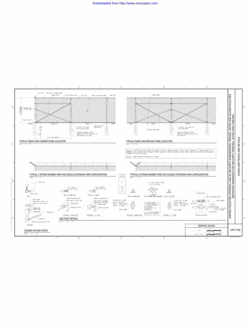
Downloaded from http://www.everyspec.com
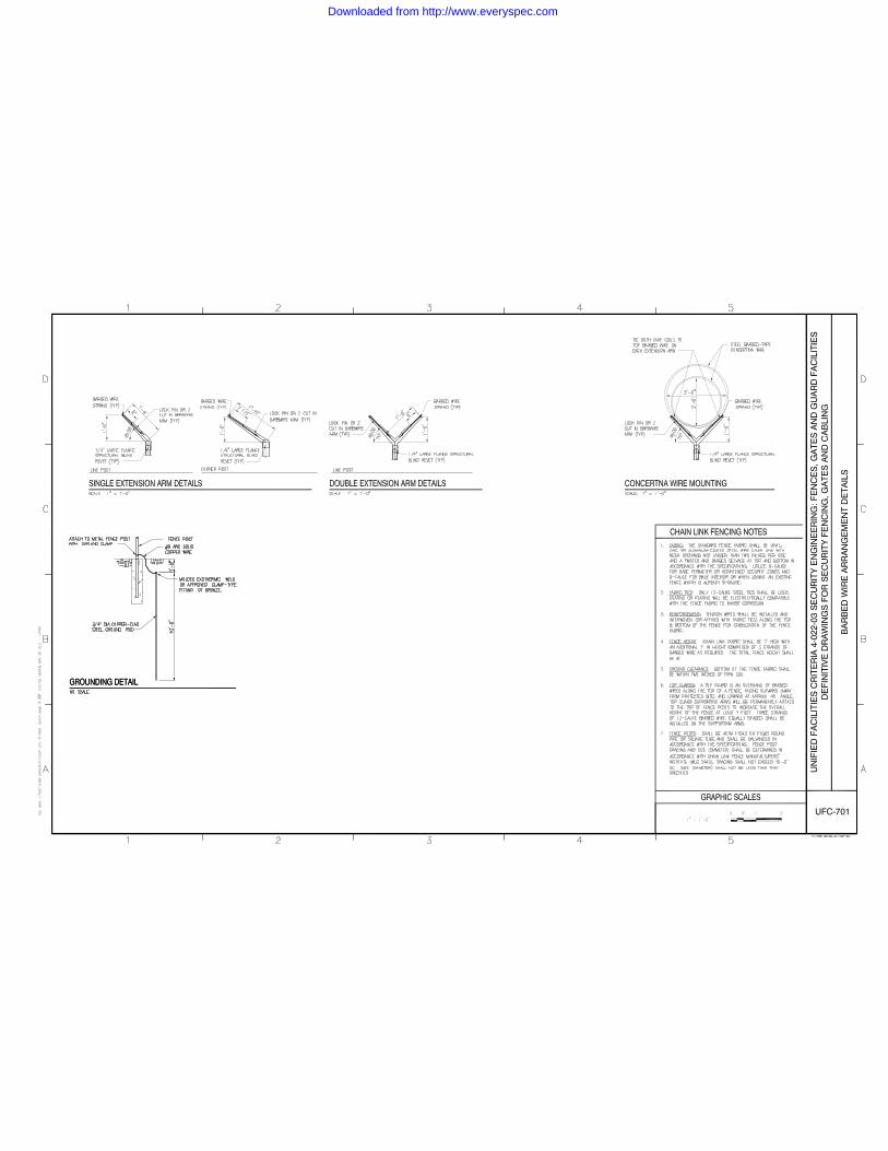
Downloaded from http://www.everyspec.com
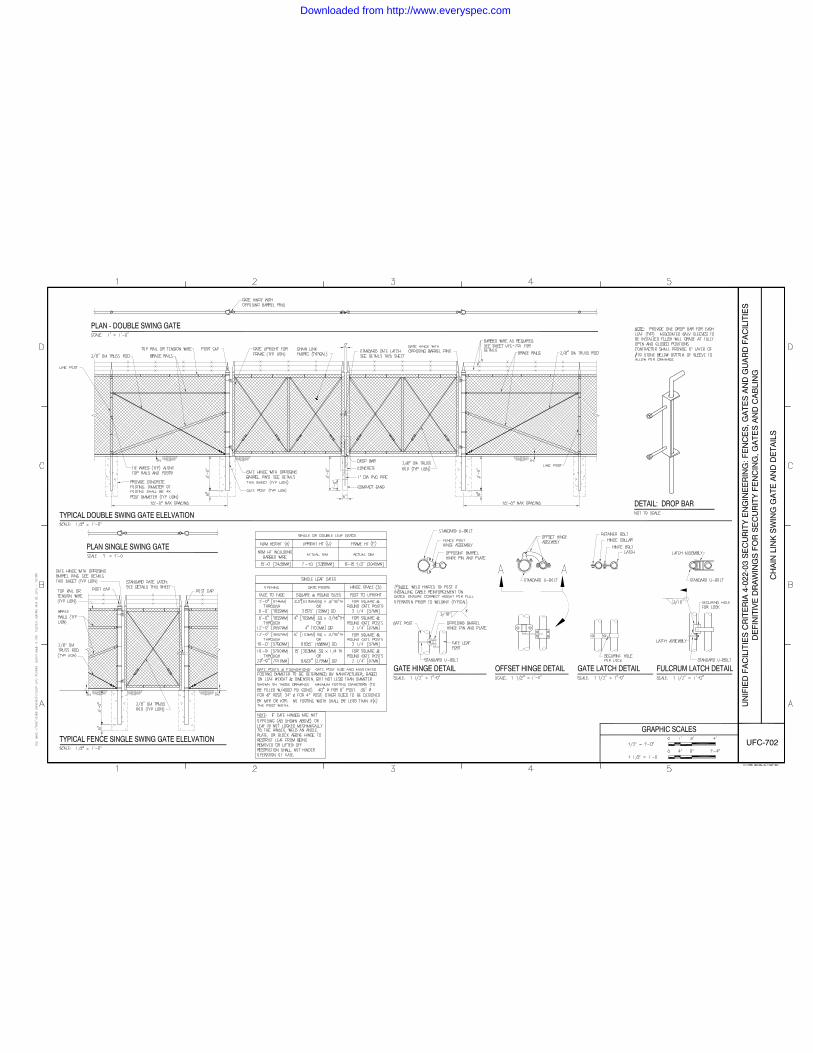
Downloaded from http://www.everyspec.com
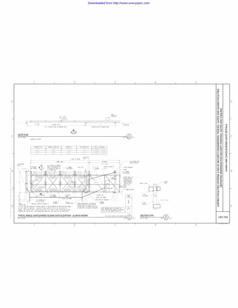
Downloaded from http://www.everyspec.com
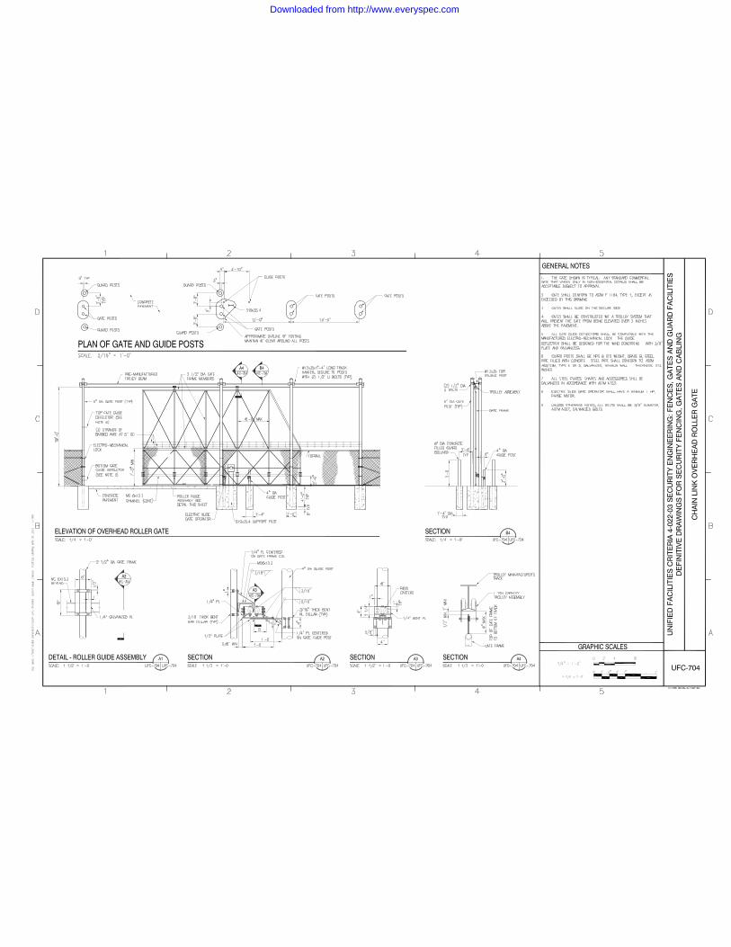
Downloaded from http://www.everyspec.com
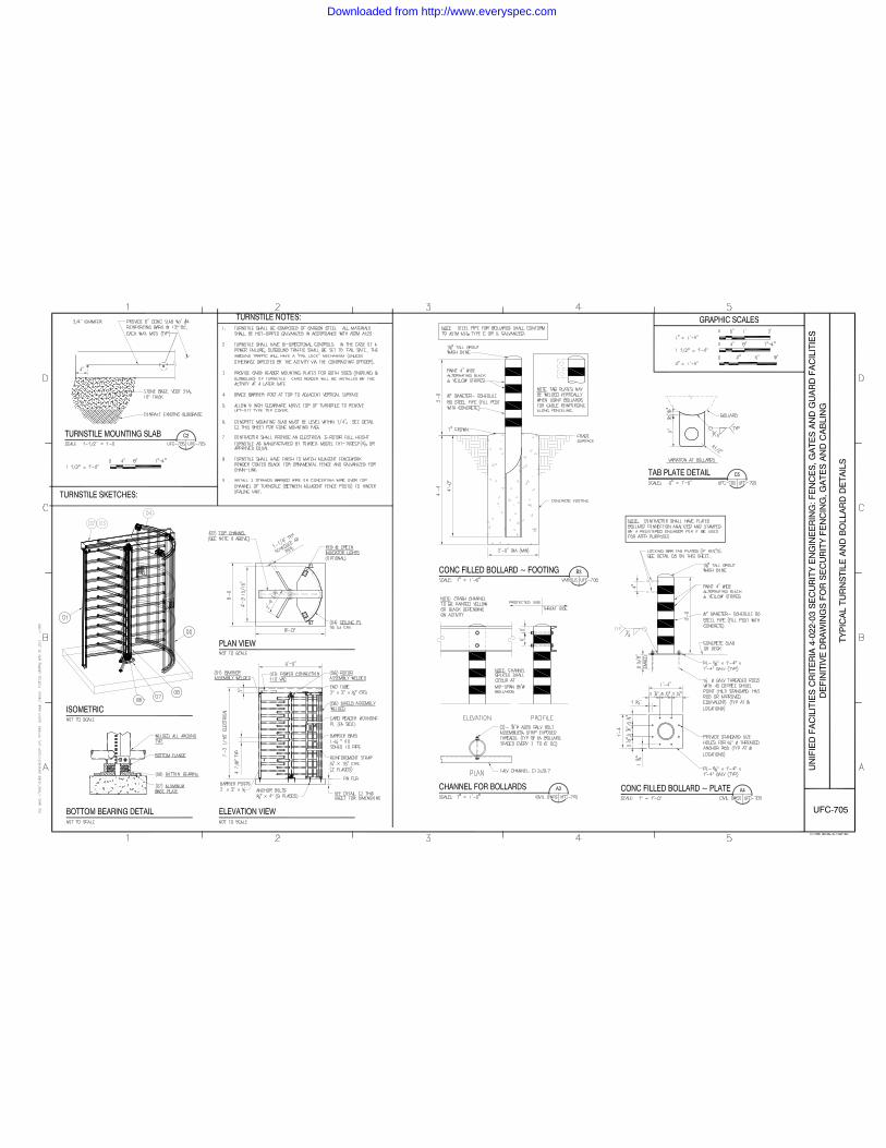
Downloaded from http://www.everyspec.com
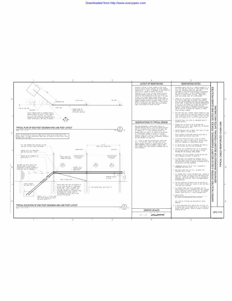
UFC 4-022-03 "Security Engineering: Fences and Gates
Downloaded from http://www.everyspec.com
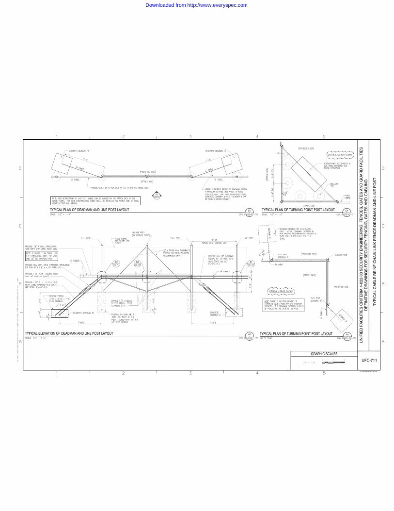
Downloaded from http://www.everyspec.com

Downloaded from http://www.everyspec.com
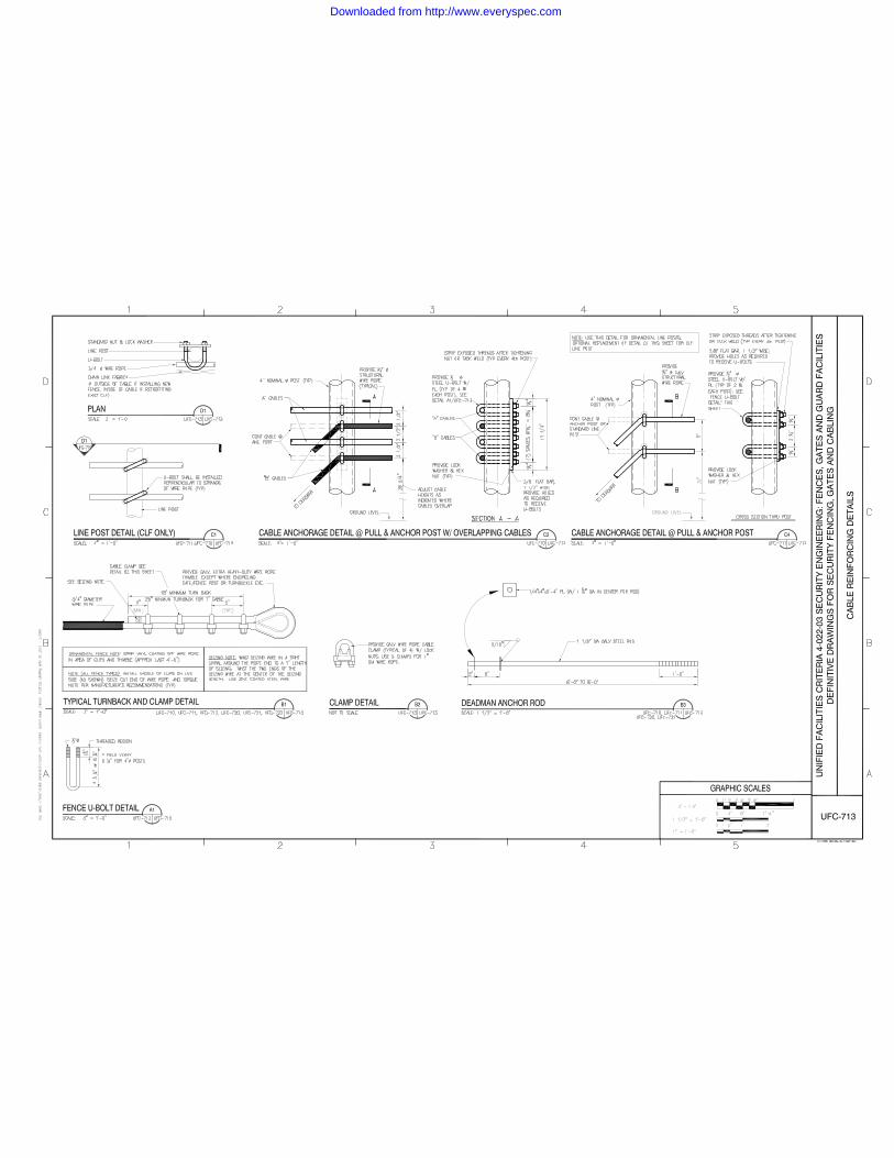
Downloaded from http://www.everyspec.com
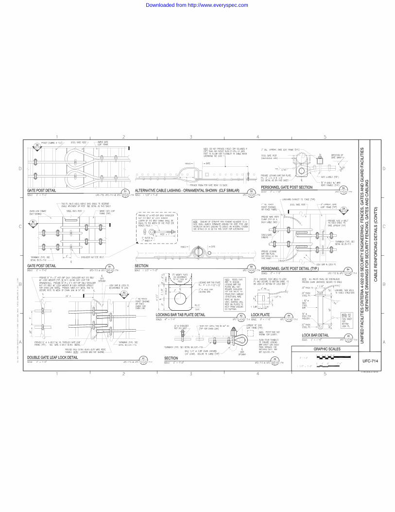
Downloaded from http://www.everyspec.com
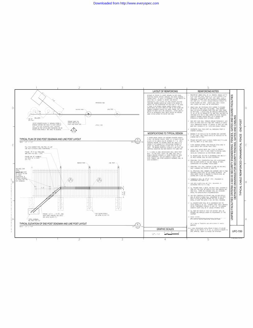
0 1�
"' 1�
= = �,�=
D
c
,�
/ I
/-\" I � ?�,�?� I
��
(1'� 2)�/,1(� 3267�
��
%2//$5'6�����
2))6(7� &21&5(7(� %/2&.� 2)� '($'0$1� 6<67(0� $�0,1,080� ',67$1&(� $1'� $1*/(� 72� $92,'� &21)/,&7�:,7+� /,1(� 3267� )281'$7,21� �7<3��� &21&5(7(�'($'0$1� � 3267� 25� %2//$5'� )281'$7,21� &$1� %(�3/$&('� 0212/,7+,&$//<�� 0$;� $1*/(� ��� '(*5((6��
2
$1&+25� 3267�--- ..........
I ?�
\ 'j
3529,'(� &$%/(� 21� _j $77$&.� 6,'(� 2)� $//�32676� $1'� )(1&(� 821�
TYPICAL PLAN OF END POST DEADMAN AND LINE POST LAYOUT 6&$/(�� ������ � 1' ����
38/,/� 3267� �&251(5� 3267�� (1'� 3267�� 25� /$67�/,1(� 3267� 72� 5(&(,9(� &$%/(� 5(,1)25&,1*�� ���������
3529,'(� ��� r/J *$/9� 6758&785$/�:,5(� 523(� 3(5� 127(� �� �7<3��
3529,'(� 0,1� ���� 7851%$&.��6((� '(7$,/� %�� 21� 6+((7�
%2//$5'6� �3(5�'(7$,/�
8)&������
%��8)&���� 0$<�%(� 3/$&('� $7� (1'�2)� &$%/(�5(,1)25&,1*� 72�3527(&7� 6(&7,216�2)� )(1&(� 7+$7� $5(�127� +$5'(1('��
���
$1&+25� 3267�
3527(&7('� 6,'(�
$77$&.� 6,'(�
C4 )&����
/,1(� 3267�
/,1(� 3267�
---------r-# .. _ _L_ _____ _
L� ,� ,��� L�,�� ,� U� ,�,��� �,� ,�� ,�1·· ·. 1 N� ·:1 ,� M� ,���� ,�,�Â�Â�ÂO� 1 ·1 �3,� � �� ��,� ,� ,���� �� ����
7<3,&$/� '($'0$1��6((� 6+((7� 8)&�����
3529,'(� ������ r/J x ������� /21*��5,*+7��+$1'� 7+5($'('� 52'� �*$/9��6((� '(7$,/� %��8)&������
TYPICAL ELEVATION OF END POST DEADMAN AND LINE POST LAYOUT 6&$/(�� ������ = 1' ����
�� 2
)25� )227,1*� '(7$,/6��6((� '(7$,/� $��8)&�����
--- ..........
I ?�
��4
���
,�,�,�,�,�,�,�,�,�,�
3
I�
3
&,9,/� ':*6� 8)&�����
��LAYOUT OF REINFORCING
'(6,*1(5� 2)� 5(&25'� 72� /2&$7(� '($'0(1� 21� 6,7(� 3/$16��6$7,6)<,1*� 63$&,1*� &5,7(5,$�� 29(5/$36�� $1'� )(1&(� &251(56� ��7851,1*� 32,176�� $7� *$7(6� ,7� ,6� '(6,5$%/(� 72� +$9(� 75$)),&� 21�(,7+(5� 6,'(� 2)� $�0(',$1� 72� 23(5$7(� $1'� 3527(&7�,1'(3(1'(17/<� �127� 87,/,=,1*� 7+(� 6$0(� '($'0$1� 6<67(06���7+(5()25(� '($'0(1� 6+28/'� %(� 3/$&('� ,1� 7+(� 0(',$1� 72�$1&+25� 7+(� *$7(� 5(,1)25&,1*� )25� ($&+� 6,'(� 2)� 7+(� 52$'��,)� 7+(5(� ,6� 12� 3+<6,&$/� 0(',$1� �0(5(/<� 3$,17('� /,1(6���/,0,7('� 5220�� 25� 87,/,7<� &21)/,&76� 7+$7� '2� 127� $//2:� )25�'($'0(1� 3/$&(0(17� %(7:((1� 7+(� *$7(6�� (1685(� 7+$7� 7+(�&$%/,1*� )25� %27+� *$7(6� $5(� &211(&7('�� (,7+(5� ',5(&7/<�25� 9,$� $1� ,17(50(',$7(� &$%/(� :+,&+� &5($7(6� $1� ,17(*5$/�&$%/(� 6<67(0� $&5266� 7+(� (17,5(� *$7(� $5($��
MODIFICATIONS TO TYPICAL DESIGN ,)� /$5*(5� '(6,*1� 7+5($76� 25� &86720(5� 5(48(676� ,1',&$7(�$�1(('� )25� *5($7(5� 6(&85,7<�� 025(� ����� r/J &$%/(6� &$1� %(�87,/,=('� 25� 7+(� &$%/(6� &$1� %(� 83*5$'('� 72� ��� r/J. %27+�6&(1$5,26� 5(48,5(� 7+(� '($'0$1� �:+,&+� :,//� 1(('� 72� %(�/$5*(5�� 72� %(� '(6,*1('� %<� $�352)(66,21$/� (1*,1((5� 72�6$7,6)<� 7+(� &5,7(5,$� 287/,1('� ,1� 5(,1)� 127(� ��� 21� 7+,6�6+((7�� )25� %,'',1*� 385326(6�� (67$%/,6+� $�81,7� &267� )25�$'',7,21$/� (;&$9$7,21� $1'� 1(:� &21&5(7(� 3(5� &8%,&� )227��
,)� ��� r/J &$%/(� ,6� 86('�� 63(&,),&$7,216� 6+$//� 0$7&+� 5(,1)�127(� �� 21� 7+,6� 6+((7�� (;&(37� 7+(� &$%/(� 6+$//� +$9(� $�0,1,080� %5($.,1*� 675(1*7+� 2)� ������� 3281'6� ���� 7216���27+(5� &20321(176�� 68&+� $6� (<(%2/76�� 8�%2/76�� 523(�&/,36�� 7+,0%/(6�� $1'� 27+(5� $662&,$7('� +$5':$5(� 6+$//� %(�6,=('� $&&25',1*/<��
8)&����� 8)&�����1---------------------1 GRAPHIC SCALES
�� �� 2' ������� � ��R�� ----
4
5 REINFORCING NOTES
��� 5(,1)25&,1*� &$%/(6� 6+$//� %(� 8�6�� '20(67,&� 0,1,080� ������ r/J �[��� &/$66� :,5(� 523(�� 5(*8/$5� /$<�� (;75$� ,03529('� 3/2:�67((/� �(,3��� ,1'(3(1'(17� :,5(� 523(� &25(� �,:5&��� &/$66� $�&21)250,1*� 72� $670� $������� $1'� *$/9$1,=('� ,1� $&&25'$1&(�:,7+� $670� $����� & +$9(� $�0,1,080� %5($.,1*� 675(1*7+� 2)�������� 3281'6� ^��� 7216��� &$%/(6� 6+$//� +$9(� $�%/$&.�9,1</� &2$7,1*�� %87� 6+$//� 127� %(� ,035(*1$7('��
��� &$%/(6� 6+$//� %(� &217,18286� )520� '($'0$1� 72� '($'0$1��12� 63/,&(6� ,1� &$%/(� 6+$//� %(� $//2:('�� &$%/(� %$55,(5�6+$//� %(� ,167$//('� %(7:((1� )(1&(� 3267� $1'� )(1&(� )$%5,&�$6� 3(5� 3/$16�� 8�%2/76� 6+$//� %(� ,167$//('� 3(53(1',&8/$5�72� 7+(� /$<� 25� 7+(� 675$1'6� 2)� 7+(� :,5(� 523(� $1'� 6+$//� %(�7,*+7(1('� $)7(5� 6$*� ,1� &$%/(� %$55,(5� +$6� %((1� 5(029('��&21&5(7(� '($'0$1� 63$&,1*� 6+$//� %(� $7� 0$;,080� ����,17(59$/6� � 7851,1*� 32,176� �(;7(51$/� &251(56���
��� :,5(� 523(� (1'6� 6+$//� 7(50,1$7(� $5281'� 7851%8&./(6�� *$7(�32676� 25� (;75$� +($9<�'87<� :,5(� 523(� 7+,0%/(6� �$7� *$7(6���7+(6(� 7(50,1$7,216� 5(48,5(� ���� 0,1,080� 2)� 523(� )25� 7851�%$&.� $1'� $�0,1,080� 2)� ���� &/,36� ($&+� �(48$/� 63$&,1*���
��� &2175$&725� 6+$//� ),(/'� 9(5,)<� $//� ',0(16,216� 35,25� 72�25'(5,1*� 0$7(5,$/6��
��� '($'0(1� 72� %(� ,167$//('� 21� 7+(� 6(&85('� 6,'(� �,17(5,25��2)� 7+(� )(1&(�� :+,/(� &$%/(6� 6+28/'� %(� ,167$//('� 21� 7+(�(;7(5,25� 6,'(� 2)� 3267��
��� 3529,'(� 1(&(66$5<� 6/$&.� ,1� &$%/(6� ^*$7(6� 21/<�� 72� $//2:�)25� )8//� 6:,1*� 2)� $//� *$7(� /($9(6��
��� 2))6(7� '($'0$1� 6<67(06� )520� )(1&(/,1(� �3/$1� 9,(:�� 72�$92,'� &21)/,&7� :,7+� (;,67,1*� )(1&(� 32676��
��� $//2:� (32;<� $1&+25� %2/76� �0,1� �� '$<6�� & &21&5(7(�'($'0(1� �0,1� �� '$<6�� 72� &85(�� 35,25� 72� $33/<,1*� /2$'6��,167$//,1*� 7851%8&./(6� � 675$,*+7(1,1*� &$%/(6���
��� $//� :(/',1*� 6+$//� %(� '21(� ,1� $&&25'$1&(� :,7+� $:6� '�����$//� :(/'� 0$7(5,$/� 6+$//� %(� (��;;� (/(&752'(6��
����� 6758&785$/� 67((/� &216758&7,21� 6+$//� %(� ,1� $&&25'$1&(�:,7+� 7+(� 1,17+� (',7,21� 2)� 7+(� $,6&� �0$18$/� 2)� 67((/�&216758&7,21� )25� $//2:$%/(� 675(66� '(6,*1��
���� 6758&785$/� 67((/� 6+$//� &21)250� 72� $670� $��� $1'� 6+$//�+$9(� $�0,1,080� <,(/'� 675(66� 2)� ������ 36,��
���� $//� 6758&785$/� 67((/� 0(0%(56� $1'� +$5':$5(� 86('� ,1� &$%/(�$1&+25,1*� 6<67(0� 6+$//� %(� +27��',33('� *$/9$1,=('�� $1<�$5($6� :+(5(� &2$7,1*� ,6� '$0$*('� 25� 5(029('� 6+$//� %(�&29(5('� :,7+� $�=,1&� 5,&+� &203281'��
���� 7851%8&./(6� 6+$//� %(� �!��[����� 7<3(� ,�� *$/9$1,=('� ,1�$&&25'$1&(� :,7+� $670� )������
���� :,5(� 523(� &/$036� 6+$//� %(� 7<3(� ,�� *$/9$1,=('�� ,1�$&&25'$1&(� :,7+� )6� ))�&������
���� $//� Q+5($'('� 52'6�� 8�%2/76�� $1'� %2/76� 6+$//� &21)250� 72�$670� $���� $1'� 6+$//� %(� ,167$//('� :,7+� )���� :$6+(56� $1'�$���� 1876�� (17,5(� %2/7� $66(0%/<� 6+$//� %(� *$/9$1,=('��,167$//� 3(5� 0$18)$&785(56� 5(&200(1'$7,216��
���� =,1&� 5,&+� &203281'� )25� 5(3$,56� 6+$//� %(� ���� 0(7$//,&�=,1&�� %<� :(,*+7� ,1� '5,('� ),/0�� &21)250,1*� 72� )('� 63(&�'2'�3������$� � 0((7,1*� 0,/,7$5<� 63(&� 0,/�3������$��,167$//� $7� /($67� 7:2� &2$76�� �� 0,/6� 0,1� 727$/� Q+,&.1(66��
���� $//� &21&5(7(� :25.� 6+$//� %(� ,1� $&&25'$1&(� :,7+� 7+(�/$7(67� (',7,21� 2)� $&,� ����� &21&5(7(� 6+$//� +$9(� $�0,1,080����'$<� &2035(66,9(� 675(1*7+� 2)� ����� 36,�� 7+(� 0,1,080�&21&5(7(� &29(5� 6+$//� %(� ���� 81/(66� 27+(5:,6(� 127('��
���� $//� ,7(06� 127� 127('� $6� �(;,67�� 25� �(;,67,1*�� 6+$//� %(�3529,'('� $1'� ,167$//('� 81'(5� 7+(� 5(48,5(0(176� 2)� 7+,6�&2175$&7��
���� '(6,*1� &5,7(5,$��8)&� ��������� �6(&85,7<� (1*,1((5,1*�� )(1&(6�� *$7(6� $1'�*8$5'� )$&,/,7,(6��
8)&� ��������� �6(/(&7,21� $1'� $33/,&$7,216� 2)� 9(+,&/(�%$55,(56���
���� ,)� &$%/(� 5(,1)25&,1*� *$7(6�� 3529,'(� (<(%2/76� 72� 6(&85(�&$%/(� 72� *$7(� 3,&.(76� @ ���� 2&� � 8�%2/76� 72� 6(&85(� 72�*$7(� 835,*+76�� 02',)<� $6� 1(('('� )25� 23(5$7,21��
5
en w �,��....J �
Cl a: <( ::> C!J(!J oz z::J <((]) en<( wO
enw wl-0<( a:iC!J LL C!J C!JZ zo a:z ww wu..
C!J-zCI: w=>
-en a: a: =>o en en (Y)C!J oz ,� �
<(Cl -w a:> -z a:_ ou.. enw wO -1-::J �0
Cl w LL �z ::>
l-en 0 a.. Cl z w w 0 z w LL ....J
z w <( z a: 0 Cl w 0 a: 0 LL z �w a: w ....J �@��
(§ ....J <( 0 �a..
UFC-720
D
c
%�
A
B3/UFC-705
UFC 4-022-03 "Security Engineering: Fences and Gates
Downloaded from http://www.everyspec.com
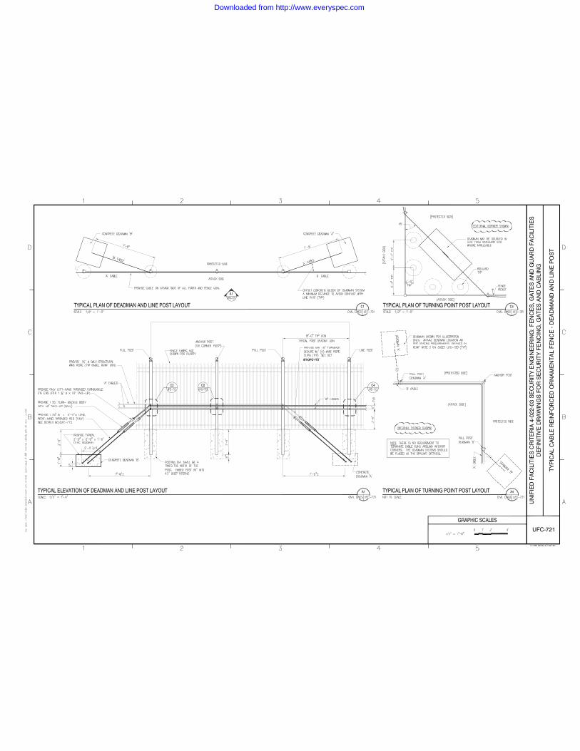
B1/UFC-713
Downloaded from http://www.everyspec.com
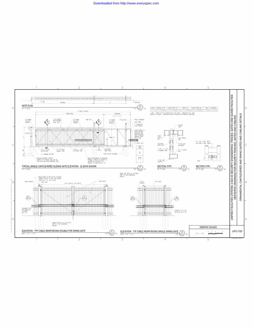
Downloaded from http://www.everyspec.com
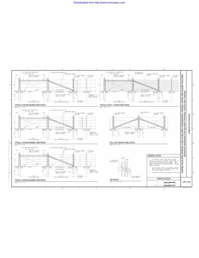
Downloaded from http://www.everyspec.com
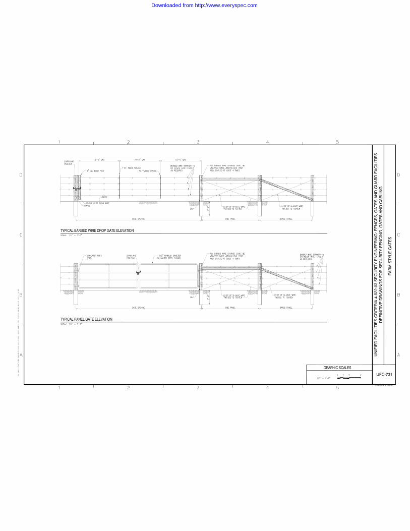
Downloaded from http://www.everyspec.com
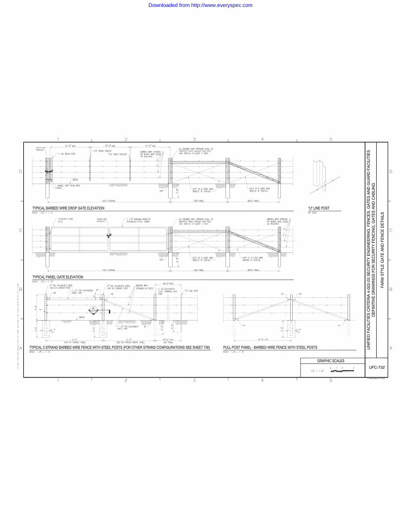
Downloaded from http://www.everyspec.com
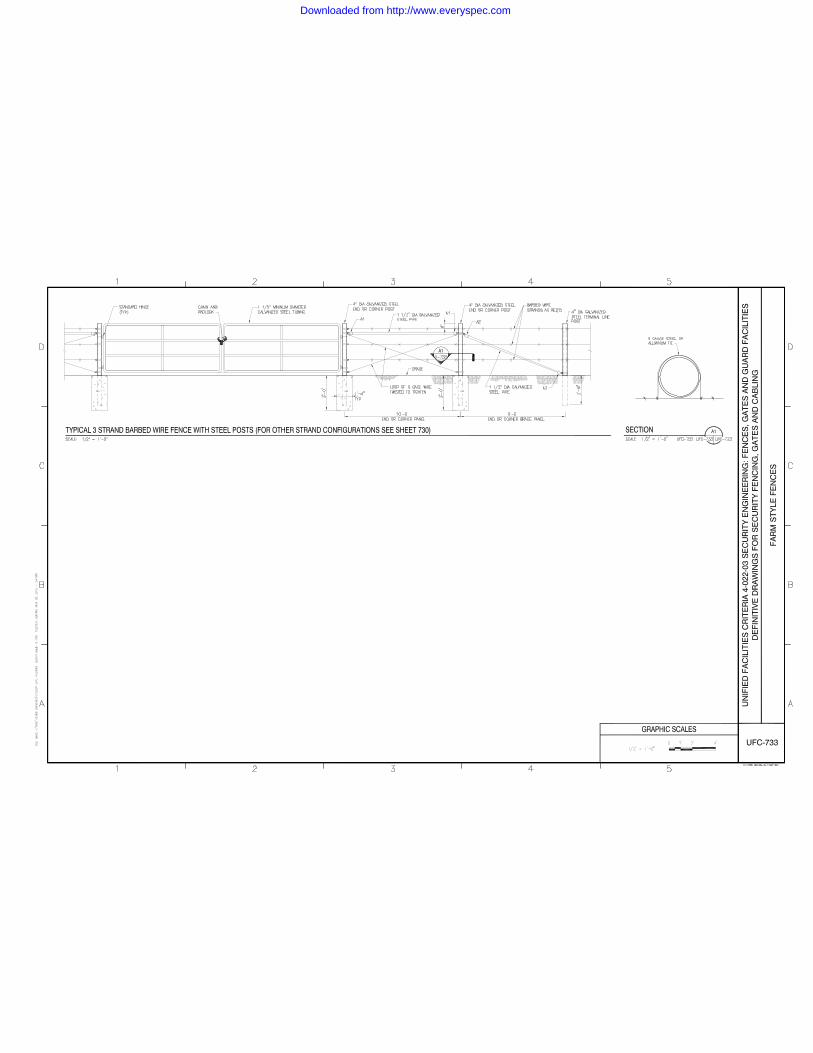
Downloaded from http://www.everyspec.com


![UNIFIED FACILITIES CRITERIA (UFC) DoD FACILITIES PRICING … · UFC 3-701-01 23 May 2018 Change 5, 3 February 2020 UNIFIED FACILITIES CRITERIA (UFC) [REVISION] SUMMARY SHEET Document:](https://img.dokumen.tips/doc/110x75/5ece76c4afcfdc39ce5e1035/unified-facilities-criteria-ufc-dod-facilities-pricing-ufc-3-701-01-23-may-2018.jpg)
![UNIFIED FACILITIES CRITERIA (UFC) DoD FACILITIES PRICING … · 2021. 2. 3. · UFC 3-701-01 23 May 2018 Change 8, 3 Feb 2021 UNIFIED FACILITIES CRITERIA (UFC) [REVISION] SUMMARY](https://img.dokumen.tips/doc/110x75/61486a752918e2056c22aca1/unified-facilities-criteria-ufc-dod-facilities-pricing-2021-2-3-ufc-3-701-01.jpg)