Embed Size (px)
Citation preview
UFC 3-201-01 1 April 2018
UNIFIED FACILITIES CRITERIA (UFC)
APPROVED FOR PUBLIC RELEASE; DISTRIBUTION UNLIMITED
CIVIL ENGINEERING
UFC 3-201-01 1 April 2018
UNIFIED FACILITIES CRITERIA (UFC)
CIVIL ENGINEERING
Any copyrighted material included in this UFC is identified at its point of use. Use of the copyrighted material apart from this UFC must have the permission of the copyright holder. U.S. ARMY CORPS OF ENGINEERS
NAVAL FACILITIES ENGINEERING COMMAND (Preparing Activity)
AIR FORCE CIVIL ENGINEER CENTER
Record of Changes (changes are indicated by \1\ ... /1/) Change No. Date Location
This UFC supersedes UFC 3-201-01, dated June 2013.

UFC 3-201-01 1 April 2018
FOREWORD The Unified Facilities Criteria (UFC) system is prescribed by MIL-STD 3007 and provides planning, design, construction, sustainment, restoration, and modernization criteria, and applies to the Military Departments, the Defense Agencies, and the DoD Field Activities in accordance with USD (AT&L) Memorandum dated 29 May 2002. UFC will be used for all DoD projects and work for other customers where appropriate. All construction outside of the United States is also governed by Status of Forces Agreements (SOFA), Host Nation Funded Construction Agreements (HNFA), and in some instances, Bilateral Infrastructure Agreements (BIA). Therefore, the acquisition team must ensure compliance with the most stringent of the UFC, the SOFA, the HNFA, and the BIA, as applicable. UFC are living documents and will be periodically reviewed, updated, and made available to users as part of the Services’ responsibility for providing technical criteria for military construction. Headquarters, U.S. Army Corps of Engineers (HQUSACE), Naval Facilities Engineering Command (NAVFAC), and Air Force Civil Engineer Center (AFCEC) are responsible for administration of the UFC system. Defense agencies should contact the preparing service for document interpretation and improvements. Technical content of UFC is the responsibility of the cognizant DoD working group. Recommended changes with supporting rationale should be sent to the respective service proponent office by the following electronic form: Criteria Change Request. The form is also accessible from the Internet sites listed below. UFC are effective upon issuance and are distributed only in electronic media from the following source:
• Whole Building Design Guide web site http://dod.wbdg.org/. Hard copies of UFC printed from electronic media should be checked against the current electronic version prior to use to ensure that they are current. AUTHORIZED BY:
LARRY D. McCALLISTER, PhD, PE, PMP, SES
JOSEPH E. GOTT, P.E. Chief Engineer
Chief, Engineering and Construction Directorate of Civil Works
Naval Facilities Engineering Command
U.S. Army Corps of Engineers
EDWIN H. OSHIBA, SES, DAF MICHAEL McANDREW Director, Air Force Civil Engineer Center (AFCEC) Air Force Installation and Mission Support Center (AFIMSC)
Deputy Assistant Secretary of Defense (Facilities Investment and Management) Office of the Assistant Secretary of Defense (Energy, Installations, and Environment)
UFC 3-201-01 1 April 2018
UNIFIED FACILITIES CRITERIA (UFC) NEW REVISION SUMMARY SHEET
Document: UFC 3-201-01, Civil Engineering Superseding: UFC 3-201-01 dated 1 June 2013 with Change 1 dated 1 March 2017. Description: UFC 3-201-01 provides civil engineering criteria and best practices for site development, grading, storm drainage, and pavements as they relate to project development. This UFC maximizes the use of industry and Government standards. This revision updates technical requirements, references, and maximizes uniformity among Tri-Service requirements. Referenced civil engineering requirements and best practices can be found in Appendices A and B.
Reasons for Document: • Establishes technical requirements by maximizing the use of industry standards
to meet DOD requirements.
• Revise format in accordance with UFC 1-300-01.
• Reorganizes the content to align with industry standards.
• Coordinates criteria requirements in other core and specialty UFC criteria documents.
• Address multiple criteria change requests.
• Includes a new Appendix C with a complete list of acronyms used in this UFC. Impact:
• This revision will have minimal impacts on design cost. Unification Issues: There are no unification issues.

UFC 3-201-01 1 April 2018
i
TABLE OF CONTENTS
CHAPTER 1 INTRODUCTION ....................................................................................... 1
1-1 PURPOSE AND SCOPE. .......................................................................... 1
1-2 APPLICABILITY. ....................................................................................... 1
1-2.1 Foreign Countries. ................................................................................. 1
1-3 OTHER CRITERIA. ................................................................................... 1
1-3.1 General Building Requirements. ............................................................ 1
1-3.2 Low Impact Development (LID). ............................................................ 1
1-4 REFERENCES. ......................................................................................... 1
1-5 BEST PRACTICES.................................................................................... 2
CHAPTER 2 SITE DESIGN ............................................................................................ 3
2-1 PLANNING. ............................................................................................... 3
2-1.1 Wetlands. ............................................................................................... 3
2-1.2 Flood Hazard Areas. .............................................................................. 3
2-2 NATIONAL ENVIRONMENTAL POLICY ACT. ........................................ 3
2-3 PRELIMINARY SITE ANALYSIS. ............................................................. 3
2-4 EXISTING CONDITIONS. .......................................................................... 4
2-4.1 Geotechnical Site Investigation. ............................................................. 4
2-4.2 Surveying. .............................................................................................. 4
2-5 APPROVALS AND PERMITS. .................................................................. 5
2-6 CLEARING AND DEMOLITION. ............................................................... 5
2-7 SITE DEVELOPMENT. .............................................................................. 5
2-7.1 Flood Hazard Areas. .............................................................................. 6
2-7.2 Flood Protection Systems. ..................................................................... 7
2-7.3 Accessibility. .......................................................................................... 7
2-8 GRADING. ................................................................................................. 7
2-8.1 Airfields. ................................................................................................. 7
2-8.2 Finished Floor Elevations. ...................................................................... 7
2-9 VEHICLE CIRCULATION. ......................................................................... 8
2-9.1 Special Circulation Areas. ...................................................................... 9
2-9.2 Traffic Studies. ....................................................................................... 9
2-9.3 Design Vehicles. .................................................................................... 9
2-9.4 Design Traffic. ........................................................................................ 9
UFC 3-201-01 1 April 2018
ii
2-9.5 Roads. ................................................................................................. 10
2-9.6 Parking Areas. ..................................................................................... 10
2-10 SITE APPURTENANCES. ....................................................................... 12
2-10.1 Pedestrian Circulation. ......................................................................... 12
2-10.2 Curb or Curb and Gutter. ..................................................................... 12
2-10.3 Wheelstops. ......................................................................................... 12
2-10.4 Bollards. ............................................................................................... 13
2-10.5 Signage and Markings. ........................................................................ 13
2-10.6 Dumpster Enclosures. ......................................................................... 13
2-11 UTILITIES. ............................................................................................... 13
2-11.1 Water Distribution Systems. ................................................................. 14
2-11.2 Wastewater Collection Systems. ......................................................... 14
2-11.3 Lighting. ............................................................................................... 14
2-12 STORM DRAINAGE SYSTEMS. ............................................................. 14
2-13 ENTRY CONTROL FACILITIES. ............................................................ 14
2-14 BRIDGES, OVERPASSES AND UNDERPASSES. ................................ 14
CHAPTER 3 STORM DRAINAGE SYSTEMS .............................................................. 15
3-1 DESIGN CRITERIA. ................................................................................ 15
3-1.1 Approved Methodologies. .................................................................... 15
3-1.2 Design Storm Frequency. .................................................................... 16
3-1.3 Maximum Spread. ................................................................................ 16
3-1.4 Inlet Design. ......................................................................................... 16
3-1.5 Erosion and Sediment Control. ............................................................ 17
3-2 MATERIAL SELECTION FOR AIRFIELDS. ........................................... 17
3-3 ROOF DRAINAGE. ................................................................................. 17
3-4 SURFACE DRAINAGE. .......................................................................... 17
3-4.1 Open Channels. ................................................................................... 18
3-5 UNDERGROUND GRAVITY STORM DRAINAGE SYSTEM. ................. 18
3-5.2 Minimum Pipe Size. ............................................................................. 20
3-5.3 Minimum and Maximum Cover. ........................................................... 21
3-5.4 Design Velocity. ................................................................................... 21
3-5.5 Manning’s Roughness Coefficient. ...................................................... 22
3-5.6 Material Selection. ............................................................................... 22

UFC 3-201-01 1 April 2018
iii
3-5.7 Culverts and Outfalls. .......................................................................... 22
3-5.8 Storm Structures. ................................................................................. 22
3-6 STORMWATER MANAGEMENT FACILITIES. ...................................... 23
3-6.1 Safety And Storm Drainage System Components. .............................. 23
3-6.2 Airfields. ............................................................................................... 23
3-7 STORMWATER PUMP STATIONS. ....................................................... 24
3-7.1 Existing Pump Stations: Upgrades and Additional Flow. ..................... 24
CHAPTER 4 PAVEMENTS ........................................................................................... 25
4-1 SURFACED AND UNSURFACED ROADS AND SITE PAVEMENTS. .. 25
4-1.1 Frost Conditions. .................................................................................. 25
4-1.2 Recycled Materials. ............................................................................. 25
4-1.3 Flexible Pavements. ............................................................................ 25
4-1.4 Rigid Pavements. ................................................................................. 25
4-1.5 Permeable Pavements. ....................................................................... 26
4-1.6 Aggregate Pavements. ........................................................................ 26
4-2 AIRFIELD PAVEMENTS AND MARKINGS. ........................................... 27
APPENDIX A REFERENCES ....................................................................................... 29
APPENDIX B BEST PRACTICES ................................................................................ 33
B-1 WHOLE BUILDING DESIGN GUIDE. ..................................................... 33
B-2 BEST PRACTICES CIVIL ENGINEERING RELATED GUIDANCE. ...... 33
B-2.1 Building Location and Orientation. ....................................................... 33
B-2.2 Flood Hazard Areas. ............................................................................ 34
B-2.3 Flood Protection Systems. ................................................................... 34
B-2.4 Vehicle Circulation. .............................................................................. 35
B-2.5 Parking Areas. ..................................................................................... 36
B-2.6 Rational Formula. ................................................................................ 40
B-2.7 Airfield Pavements. .............................................................................. 40
B-3 BEST PRACTICE REFERENCES........................................................... 40
APPENDIX C GLOSSARY ........................................................................................... 43
C-1 ACRONYMS ............................................................................................ 43
UFC 3-201-01 1 April 2018
iv
FIGURES
Figure 3-1 Deflection at Structures ...................................................................... 18
TABLES
Table 2-1 Grading ..................................................................................................... 8 Table 3-1 Storm Structure Spacing Criteria ......................................................... 19 Table 3-2 Minimum Invert Elevations ................................................................... 20 Table 3-3 Design Velocity ...................................................................................... 21 Table B-1 Parking Space Guidelines for Non-Organizational Vehicles .............. 36
This Page Intentionally Left Blank
UFC 3-201-01 1 April 2018
1
CHAPTER 1 INTRODUCTION
1-1 PURPOSE AND SCOPE.
This UFC provides civil engineering requirements for all new and renovated Government facilities for the Department of Defense (DoD). Where other criteria, statutory or regulatory requirements, are referenced, the more stringent requirement must be met.
1-2 APPLICABILITY.
This UFC applies to all service elements and contractors involved in the planning, design and construction of permanent DoD facilities worldwide. It is applicable to all methods of project delivery and levels of construction.
1-2.1 Foreign Countries.
All design and construction outside of the United States and United States territories is governed by international agreements, such as the Status of Forces Agreements (SOFA), Host Nation-Funded Construction Agreements (HNFA), and in some instances, Bilateral Infrastructure Agreements (BIA), and country-specific Final Environmental Governing Standards (FGS) or DoDI 4715.05. DoDI 4715.05 is commonly referred to as the Overseas Environmental Baseline Guidance Document (OEBGD). The OEBGD applies when there are no FGS in place. Therefore, in foreign countries this UFC will be used for DoD projects to the extent that it is allowed by and does not conflict with the applicable international agreements and the applicable FGS or OEBGD.
1-3 OTHER CRITERIA.
1-3.1 General Building Requirements.
Comply with UFC 1-200-01, DoD Building Code (General Building Requirements). UFC 1-200-01 provides applicability of model building codes and government unique criteria for typical design disciplines and building systems, as well as for accessibility, antiterrorism, security, high performance, sustainability, and safety. Use this UFC in addition to UFC 1-200-01 and the UFCs and government criteria referenced therein.
1-3.2 Low Impact Development (LID).
Use UFC 3-210-10 for LID criteria. UFC 3-210-10 was developed to comply with the DoD Memorandum implementing Section 438 of the Energy Independence and Security Act (EISA).
1-4 REFERENCES.
Appendix A contains the list of references used in this document. The publications, standards, and technical data referenced herein form a part of these criteria to the extent referenced. Unless otherwise specified, the most recent edition of the referenced publication applies.

UFC 3-201-01 1 April 2018
2
1-5 BEST PRACTICES.
Appendix B provides guidance for accomplishing certain civil design and engineering services. The Designer of Record (DoR) is expected to review and interpret this guidance as it conforms to criteria and contract requirements, and apply the information according to the needs of the project. If a Best Practices document has guidelines or requirements that differ from any UFC or the Unified Facilities Guide Specifications (UFGS), the UFC and the UFGS must be given a higher order of precedence.
UFC 3-201-01 1 April 2018
3
CHAPTER 2 SITE DESIGN
2-1 PLANNING.
Site planning requires knowledge of environmental requirements, land use restrictions, building setbacks, flood hazard areas, utility connections, utility offsets, vehicle circulation, buffers from natural and manmade features and other similar requirements. Use this UFC prior to starting design to determine specific project requirements (e.g., demolition, site development, water distribution, wastewater collection). Avoid flood hazard areas and wetlands to the extent practical.
2-1.1 Wetlands.
EO 11990 directs all Federal agencies to avoid wetlands development wherever there is a practicable alternative.
2-1.2 Flood Hazard Areas.
EO 11988 directs all Federal agencies to avoid floodplain development wherever there is a practicable alternative. When development within the floodplain is considered, evaluate alternative site locations to avoid or minimize adverse impacts to the floodplain.
When mission needs require constructing within the 100-year floodplain, include flood mitigation measures as part of the project and document on DoD Form 1391.
2-2 NATIONAL ENVIRONMENTAL POLICY ACT.
National Environmental Policy Act (NEPA) actions should be completed prior to starting design. Obtain NEPA documentation prepared for the project from the Installation environmental staff and comply with the identified measures and include them as contract requirements.
2-3 PRELIMINARY SITE ANALYSIS.
Use UFC 2-100-01 to develop a preliminary approach appropriate to the site and adjacent facilities and integrates sustainable strategies, utilizing a holistic design approach. Conduct a preliminary site visit and obtain photographs of the site. Research and obtain Installation’s master plan, utility maps, and as-built record drawings for information related to topography, utility and storm drainage availability, including design approaches used in the project vicinity. Evaluate the potential for abandoned or unmapped utilities. Research and review available subsurface investigation data and reports in order to evaluate subsurface conditions. Identify flood hazard areas in accordance with the International Building Code (IBC) Section 1612, Flood Loads. Research and obtain explosive safety requirements. Consult with the Government Project Manager to establish contact with the Installation’s Environmental personnel to determine if the site has environmental concerns, such as radon, pesticides, or known contamination. If required, provide radon mitigation system design
UFC 3-201-01 1 April 2018
4
in accordance with UFC 3-101-01. Evaluate the need for additional analysis based on project requirements and site conditions.
Conduct detailed consultations with the Government in order to clearly define requirements and preferences.
2-4 EXISTING CONDITIONS.
2-4.1 Geotechnical Site Investigation.
Obtain soil exploration, testing, and evaluation from a professional geotechnical engineer. Determine the extent of exploration and testing based on recommendations with the geotechnical engineer, structural engineer (for foundations), civil engineer (for LID, pavements, wells, septic systems, etc.), local stormwater permitting agency (for detention ponds), and Government reviewers. Soils investigation (sampling, testing, and evaluation) must be in accordance with UFC 3-220-01, UFC 3-250-01, and UFC 3-260-02.
Indicate the results of the subsurface investigation, including boring locations, boring logs, groundwater observations, a summary of laboratory test results, and any details required to convey requirements for site preparation on the contract documents.
2-4.2 Surveying.
Unless provided by Government personnel, a licensed or certified professional must seal all surveys in accordance with the applicable requirements of the local regulatory agency or overseas equivalent having jurisdiction over the installation. Where overseas equivalent requirements do not include an accuracy standard, provide surveys at a minimum third order in accordance with National Oceanic and Atmospheric Administration (NOAA), Federal Geodetic Control Committee, Standards and Specifications for Geodetic Control Networks.
Prior to entering property not owned by the Government, consult with the Government Project Manager to establish contact with the Installation’s real estate personnel. Notify and obtain authorization for a right of entry (i.e., trespass) over, across, or through all lands public or private landowners necessary to perform required field survey work. Coordinate with the Installation’s Security section for approval to enter controlled or restricted areas (e.g., airfields, ranges, munition storage). Consult with Government Project Manager to establish contact with the Installation’s Environmental personnel before entering the area with regards to any restrictions concerning cutting or clearing vegetation, natural resources, endangered species, etc.
2-4.2.1 Topographic Surveys.
Provide a topographic survey of the project site in accordance with each service’s requirements as well as the requirements of the state or Host nation equivalent in which the site is located. If state or Host nation equivalent requirements are not available, use the National Society of Professional Surveyors (NSPS) Model Standards for Topographic Surveys.

UFC 3-201-01 1 April 2018
5
2-5 APPROVALS AND PERMITS.
The DoR must identify, assist, and provide, as applicable, all permits, approvals, and fees required for the design and construction of the new project from Federal, state and local regulatory authorities or overseas equivalent. The Civil Engineering DoR must be a Professional Civil Engineer experienced and licensed. Licensure in the location of the project may be required to obtain permits and approvals. In the United States and its territories and possessions the Government will review permits for acceptability. In locations outside of the United States and its territories and possessions with Host nation agreements, follow permit approval procedure as directed in project scope and by the Government Project Manager. In locations outside of the United States and its territories and possessions without Host nation agreements, the Government will review and approve site improvement plans for compliance.
Consult with the Government Project Manager to determine the appropriate signatories for permit applications.
2-6 CLEARING AND DEMOLITION.
Identify the following in the construction documents: limits of disturbance; limits of demolition; limits of clearing and grubbing; isolated trees and shrubs to remain or to be removed. Describe size, density, and type of trees to be cleared and grubbed, items to be salvaged or relocated, staging area, temporary storage area and location. Coordinate with the Installation concerning clearing options to remove merchantable timber from the project site.
During site demolition and preparation, remove existing and abandoned utilities under or within 10 feet (3.0 m) of the foundation of any new facility or building foundation. Reroute existing utilities to remain in accordance with paragraph titled “UTILITIES” in Chapter 2.
2-7 SITE DEVELOPMENT.
Location and orientation of facilities must be based on an analysis of activities to be accommodated and on specific requirements for each project, to include all functional, technical, and economic factors. Use UFC 3-101-01 for building function, size and orientation criteria.
Incorporate the following into site design, as applicable:
a. Land use restrictions and setbacks (existing and future). b. Circulation (vehicle and pedestrian). c. Orientation and Location to integrate green space. Provide adequate
grading and drainage while preserving natural topographic features to minimize cut and fill, impact on existing drainage patterns and tree removal.
d. Operational and natural constraints. 1. Maintain mandated buffers:

UFC 3-201-01 1 April 2018
6
(a) Airfield and helipad clearances. (b) Explosives safety clearances. (c) Noise abatement. (d) Antiterrorism and physical security clearances. (e) Storage and handling hazardous material clearances. (f) Separation of incompatible land use or functions.
(g) Building setbacks (if established). (h) Fire separation zones per building and fire codes.
2. Eliminate or minimize construction activities requiring permits for areas such as archaeological sites, wetlands, utilities, and stormwater management.
3. Minimize site or utility maintenance and operating costs. 4. Accommodate site constructability and security requirements. 5. Minimize distance to existing utility connections.
2-7.1 Flood Hazard Areas.
Where a new project site occupies two or more flood hazard areas, site the structures or most vulnerable structures to avoid the flood hazard area that presents the highest risk to the extent practicable. When avoiding a higher risk flood hazard area is not practicable, meet the minimum design requirements for the flood hazard area that presents the highest risk to the structures. In some cases, it may be acceptable to design portions of structures that are structurally independent.
Project sites located in flood hazard areas must be designed in accordance with UFC 1-200-01. UFC 1-200-01 implements the IBC and the IBC implements ASCE 24-14. The boundaries of all Flood Hazard Areas must be designated by:
a. The applicable Flood Insurance Study (FIS) with the accompanying Flood Insurance Rate Map (FIRM) and Flood Boundary and Floodway Map (FBFM) issued by Federal Emergency Management Agency (FEMA), when available;
b. A map adopted by the Installation showing special flood hazard areas identified by FEMA with more detail then the applicable FIRM;
c. A map adopted by the Installation when an applicable FEMA FIS is not available or;
d. by determining the design flood elevation in accordance with FEMA accepted hydrologic and hydraulic engineering practices used to define flood hazard areas.
Ensure proper correlation between vertical datums. Submit calculations to the Government Civil Engineer and document the governing criteria used.

UFC 3-201-01 1 April 2018
7
2-7.1.1 Existing Buildings.
Refer to UFC 1-200-01, Chapter 4, and paragraph titled “General” for existing buildings.
2-7.2 Flood Protection Systems.
Flood protection dams, levees, floodwalls, and other types of flood protective works.
2-7.2.1 Buildings and Structures.
Use flood protection systems where the minimum requirements in IBC Section titled “Flood Loads” and ASCE 24 cannot be met or an engineering and cost analysis indicates that it is advantageous to the intent of the project. At a minimum, design flood protection systems to protect a facility or a group of facilities from the 1% annual chance flood. Use 44 CFR Section 65.10 to determine minimum design requirements (i.e., freeboard). Refer to best practice document FEMA GD34 for additional guidance.
2-7.2.2 Roads.
For roads and similar infrastructure, add a minimum 1 foot of freeboard to the design flood elevation.
2-7.3 Accessibility.
Use UFC 1-200-01 to determine accessibility requirements.
2-8 GRADING.
UFC 1-200-01 implements grading requirements from the IBC and provides supplements to IBC criteria. Use UFC 1-200-01, paragraph titled “Soils and Foundations”, to determine the appropriate requirements for site grading. Grading must direct water away from impervious site features (i.e., buildings, structures, runways, roads) and towards new or existing drainage features. Grading must not result in low spots that hold water or that direct water towards new or existing site features. Conform to existing topography to the greatest extent possible.
Crowned sections are the standard cross sections for roads, runways, taxiways, and safety areas. Crowned sections are generally symmetrical and slope away from the center line of the pavement.
2-8.1 Airfields.
Use the airfield grading criteria in UFC 3-260-01.
2-8.2 Finished Floor Elevations.
Establish minimum finished floor elevations in accordance with this UFC, UFC 1-200-01, paragraph titled “Structural Design”, IBC Section titled “Flood Loads”, ASCE 24-14, and UFC 3-101-01 whichever is more stringent.

UFC 3-201-01 1 April 2018
8
2-8.2.1 Transverse and Longitudinal Slopes.
Acceptable ranges of transverse and longitudinal slopes are indicated in Table 2-1. Grading criteria is also indicated in AASHTO GDHS.
Table 2-1 Grading
Item Item Description Requirement Best Practices
1 Longitudinal grades of roads Min. 0.3% Min. 0.5% 2 Transverse grades of roads Min. 2.0%
3 Concrete pavement in parking areas Min. 1.0%
Min. 1.5% Max. 5.0%
4 Curb & Gutter or Valley Gutter Min. 0.3% Min. 0.5%
5 Bituminous pavement in parking areas Min. 1.5%
Min. 2.0% Max. 5.0%
6 Permeable Pavements in parking areas* Min. 1.0% Max. 5.0%
7 Walks, Transverse Max. 2.0% 8 Walks, longitudinal Max. 5.0% 9 Concrete Landings Max. 2.0%
10 Paved Concrete Ditches, longitudinal Min. 0.3%
11 Unpaved Ditches, longitudinal* Min. 0.5%
12 Pervious Surfaces (Grass, Turf, or Landscape)* Min 2.0%
* Regulatory agency’s stormwater management criteria may govern for items used as stormwater management features.
2-9 VEHICLE CIRCULATION.
The DoR must address unique aspects of military facilities when designing roads and parking. For example, roads on military installations are typically designed for lower speeds while also addressing the movement of specialized military vehicles. Roads, parking areas and structures must conform to current antiterrorism and handicap accessibility requirements.

UFC 3-201-01 1 April 2018
9
2-9.1 Special Circulation Areas.
Circulation areas for other than normal passenger car traffic have special requirements to maintain traffic safety. These areas require additional space to accommodate unusual traffic patterns and greater turning radii for maneuverability. Special circulation areas include areas such as drop off areas, delivery and service zones, garbage collection areas (i.e., dumpsters), drive-in facilities, emergency vehicle access, and entry control facilities. The design must also address the turning and reverse movements for the largest vehicle (e.g., deliveries, emergencies, and garbage collection) that will use the facility and discourage through traffic.
2-9.1.1 Dumpster Pads.
Maintain a forward movement for dumpster trucks for access to and from the dumpster pad. Provide a straight approach for dumpster trucks to access the pad and align with the dumpster, reverse away from the pad, and exit forward from the site.
2-9.1.1.1 Airfields.
Locate dumpsters in locations approved by Airfield Operations (AIROPS) to avoid a Bird/Animal Aircraft Strike Hazard (BASH) issue.
2-9.2 Traffic Studies.
Provide traffic studies and analysis in accordance with SDDCTEA Pamphlet 55-17 and SDDCTEA Pamphlet 55-8.
2-9.3 Design Vehicles.
Design vehicle types include:
a. Passenger car, truck, light-delivery truck, bus, and truck combinations are as defined by AASHTO (e.g., moving vans, refuse trucks and school buses, snow-clearing trucks).
b. Emergency vehicles. c. Specialized military vehicles (e.g., tracked vehicles).
Obtain design information for emergency vehicles and specialized military vehicles from the Government Project Manager.
2-9.4 Design Traffic.
Use ITE LP-674B to evaluate average daily traffic (ADT) and peak hourly traffic, as applicable. Adjust for vehicles other than passenger cars. In addition to the vehicles indicated in ITE LP-674B (e.g., trucks, RV’s, buses), add specialized military vehicles as a vehicle type and determine the nearest equivalent AASHTO vehicle type.

UFC 3-201-01 1 April 2018
10
2-9.5 Roads.
Design roads in accordance with SDDCTEA Pamphlet 55-17, AASHTO GDHS, AASHTO RSDG-4, and AASHTO VLVLR as applicable.
Single-lane roads may be provided for fire lanes and approach drives to buildings within built-up areas. Access roads to unmanned facilities may also be single-lane roads. Where shoulders are not sufficiently stable to permit all-weather use and the distance between intersections is greater than ½-mile (805 m), turnouts must be provided at 1/4-mile (402 m) intervals along single lane roads for use by occasional passing or meeting vehicles.
2-9.5.1 Fire Lane and Emergency Vehicle Access.
Fire lanes and emergency vehicle access must comply with UFC 3-600-01.
2-9.6 Parking Areas.
Design parking areas in accordance with SDDCTEA Pamphlet 55-17, Chapter titled “Parking”. Parking areas include on-street parking, off-street parking lots, and parking structures. Refer to scope of work to determine the gross area or number of parking spaces. If the number of parking spaces is not identified in the project scope of work, use Table B-1 for guidance. Provide parking spaces primarily by off-street parking areas or structures.
2-9.6.1 On-Street Parking.
The use of on-street parking is discouraged. On-street parking will not be allowed within 20 feet (6.1 m) of an intersection. The minimum length for the first and last stall is 20 feet (6.1 m). The minimum length for each interior stall is 22 feet (6.7 m).
Exception to SDDCTEA Pamphlet 55-17: The minimum width for all passenger vehicle stalls is 8 feet (2.4 m).
2-9.6.2 Off-Street Parking.
Typically 90 degree parking is preferred for off-street parking for ease of traffic flow. If 90 degree parking is not used, the designer must be able to justify by showing that the minimum functional and technical requirements are met while providing an economic benefit to the Government. Provide minimum 9 feet (2.7 m) wide and 18.5 feet (5.6 m) long parking spaces for 90 degree parking. The design must discourage through traffic.
Exception to SDDCTEA Pamphlet 55-17: In areas of limited space, provide a minimum buffer strip of 8 feet (2.4 m) when sufficient space is available.

UFC 3-201-01 1 April 2018
11
2-9.6.3 Compact Cars.
Compact spaces may be used when there will be a consistent number of compact size vehicles accessing the facility on a regular basis. Do not use compact spaces when sufficient space is available for standard size passenger vehicles.
2-9.6.4 Motorcycles.
When motorcycle spaces are subtracted from the required regular spaces a parking study must be performed to determine the consistent number of motorcycles regularly parking at the facility throughout the year. When performing the traffic study, take into account adverse weather (e.g., winter in northern climates). Do not subtract motorcycle spaces from required regular spaces unless supported by a traffic study.
Motorcycle parking surfaces are typically designed as rigid pavements to prevent kickstands from penetrating bituminous pavement in warm weather. The minimum size for motorcycle spaces is 9 feet (2.7 m) long and 4.5 feet (1.3 m) wide.
2-9.6.5 Petroleum, Oil and Lubrication (POL) Parking Areas.
Use UFC 3-460-01 for POL criteria.
2-9.6.6 Parking Areas Outside of the United States.
Use UFC 1-200-01 and refer to the “Forward” at the beginning of this UFC to determine accessibility requirements for areas outside of the United States. When standard passenger car dimensions, as indicated in SDDCTEA Pamphlet 55-17, are not used, a traffic engineering study (e.g., parking study, parking design vehicle study) must be performed to determine the predominant vehicle size and parking layout. Perform traffic engineering studies in accordance with SDDCTEA Pamphlet 55-8. The minimum parking size for all cars is 8 feet (2.4 m) x 16 feet (4.8 m).
During the parking study, take into account the following at a minimum:
a. Requirements for each project. b. An analysis of activities to be accommodated. c. Government vehicle use. d. Standard vehicles from the United States. e. Current and future parking demand. f. Variety of parking areas needed. g. Truck traffic (e.g., deliveries, garbage collection). h. Emergency vehicles. i. Minimum entrance widths. j. Number of entrances. k. AT setbacks.

UFC 3-201-01 1 April 2018
12
m. Parking (on-street, off-street, parking orientation, aisle widths, minimum stall size and orientation, accessible spaces).
2-10 SITE APPURTENANCES.
Provide site appurtenances in accordance with state or local standards where project is located.
2-10.1 Pedestrian Circulation.
Provide a network of sidewalks, separated from, but connected to vehicular circulation systems, to allow for pedestrian circulation between various new and existing elements of the project. Interface new pedestrian circulation systems with existing pedestrian circulation systems. Consult the Government Project Manager for any special walk requirements for such facilities as barracks, where extra wide walks may be required for marching or muster formation.
Use SDDCTEA Pamphlet 55-17 for the design of pedestrian circulation systems including marking and signs. Sidewalks may consist of portland cement concrete, bituminous concrete (asphalt), solid pavers, permeable pavers, or pervious concrete. The minimum width for walks is 4 feet (1.2 m). The minimum thickness of PCC concrete sidewalks is 4 inches (100 mm). Provide bituminous sidewalks with a minimum 4 inches (100 mm) thick base and a 1 inch (25 mm) thick bituminous surfacing. Use Best Practices document, AASHTO GPF for additional design guidance.
2-10.2 Curb or Curb and Gutter.
Use concrete curb and gutter when overland flow cannot be achieved; to extend curb or curb and gutter from an adjacent facility; or to confine traffic. Asphalt-type curbs are only allowed in remote areas where approved by the Installation.
2-10.2.1 Airfields.
Curbs and gutters are not permitted to interrupt surface runoff along a runway, taxiway, heliport, or apron. The runoff must be allowed unimpeded travel transversely off the runway and then directed to the inlets.
2-10.2.2 Open Channels.
Open channels or natural water courses are permitted only at the periphery of an airfield or heliport facility and must be well removed from the landing strips and traffic areas.
2-10.3 Wheelstops.
Provide 6 feet (1.8 m) long wheelstops anchored to the pavement at parking spaces adjacent to sidewalks, buildings, stormwater management facilities, areas of extreme slope, and other areas without curb where a vehicle would likely cause property damage. Locate the front face of the wheelstop 30 inches (750 mm) from the edge of the pavement or sidewalk.

UFC 3-201-01 1 April 2018
13
Where snow removal equipment is used, wheelstops may not be allowed by the Installation; coordinate with Government Project Manager.
2-10.4 Bollards.
2-10.4.1 Bollards around Structures.
Provide bollards around any structures subject to damage from vehicular traffic by incidental contact; such bollards must be at minimum 4 feet (1.2 m) high. For steel bollards, provide minimum 4 inch (100 mm) diameter filled with concrete and painted. Bollards on aircraft aprons protecting fire hydrants must not exceed 30 inches (750 mm) aboveground and 24 inches (600 mm) above load bearing paving.
2-10.4.2 Bollards for Security.
For vehicular barrier and crash rated applications, use UFC 4-022-02.
2-10.5 Signage and Markings.
Provide signs and associated pavement markings to facilitate proper utilization of the project site. Provide new traffic control devices (e.g., signs, markings) in accordance with SDDCTEA Pamphlet 55-17. Also use MUTCD, SHSM and Department of Defense Supplement to the National Manual on Uniform Traffic Control Devices.
Provide non-reflectorized pavement markings for paved parking areas, reflectorized pavement markings for paved roads, and fire access markings in accordance with marking criteria and procedures recognized by the Department of Transportation (DOT) in the state in which the project is located or local governing authority’s requirements.
2-10.6 Dumpster Enclosures.
Where dumpster pads are required on a project, provide a dumpster pad enclosure conforming to the Installation Appearance Plan.
2-11 UTILITIES.
New underground utilities (e.g., water, sanitary sewer, electrical, telecommunications, natural gas) must be at least 10 feet (3.0 m) from facility or building foundations, except for building connections. Provide horizontal and vertical separation between new and existing utilities for rehabilitation, maintenance, repair or replacement. Minimize underground utilities located beneath pavements, except where crossings are required. Locate utilities to minimize connection costs and traffic interference with future maintenance.
Obstructions including signs and poles for overhead utilities must be located outside the limits of usable shoulder on roads designed without barrier curbs. Where practicable, roads designed with barrier curbs must have the desirable lateral clearances to obstructions as indicated in AASHTO GDHS except that fire hydrant clearances must be in accordance with UFC 3-600-01.

UFC 3-201-01 1 April 2018
14
2-11.1 Water Distribution Systems.
Use UFC 3-230-01 for water distribution system criteria. Use UFC 3-230-03 to establish water demand.
2-11.2 Wastewater Collection Systems.
Use UFC 3-240-01 for wastewater collection system criteria. Use UFC 3-240-02 to establish wastewater flows.
2-11.3 Lighting.
Use UFC 3-530-01 for lighting criteria.
2-12 STORM DRAINAGE SYSTEMS.
Refer to Chapter 3 of this UFC.
2-13 ENTRY CONTROL FACILITIES.
Use UFC 4-022-01 and SDDCTEA Pamphlet 55-15 for entry control facility criteria.
2-14 BRIDGES, OVERPASSES AND UNDERPASSES.
Where applicable, comply with AASHTO GDHS, AASHTO RSDG-4 and AASHTO HB. Use Best Practices document USDA 0625 1808P as applicable.
For railroad bridges comply also with UFC 4-860-01FA, the design manual of the relevant railroad company and use Best Practices document, the American Railway Engineering and Maintenance-of-Way Association (AREMA) publication Manual for Railway Engineering.
UFC 3-201-01 1 April 2018
15
CHAPTER 3 STORM DRAINAGE SYSTEMS
3-1 DESIGN CRITERIA.
Design surface drainage, underground drainage systems, stormwater management facilities, and erosion and sediment control in accordance with the criteria noted in this UFC, UFC 3-210-10, HDS-5, state drainage manual, or the local regulatory agency with jurisdiction over the Installation; whichever is more stringent. Ensure that the stormwater runoff does not adversely affect surrounding sites. Submit calculations to the Government Civil Engineer and document the governing criteria used. For additional design guidance, consult Best Practices documents, as indicated in Appendix B and manufacturer’s data.
The design of the storm drainage system and stormwater management features must address the following:
a. The storm drainage system and stormwater management plan must comply with Federal, state, and local regulatory requirements including regional or site-specific stormwater management agreements.
b. Minimize grading to complement the features and functions of the natural drainage system and the existing contours.
c. The siting and sizing of stormwater management facilities must take into account the high and seasonal groundwater table elevations.
d. Utilize overland flow and natural site features where storm drainage will not impact site function or adversely affect surrounding sites. Drainage systems must prevent erosion of existing soils, ponding, and convey flow to a suitable outfall location.
e. Culverts, ditches, and other drainage structures must be designed to minimize adverse environmental effects (e.g., impacts to wetlands, blocking fish passage).
f. If a suitable point of discharge does not exist, one must be constructed. 3-1.1 Approved Methodologies.
Time of concentration must be calculated using the Rational Method for drainage areas smaller than 200 acres, TR-55 curve number method or as approved by the Government Civil Engineer. Intensity-duration-frequency (IDF) curves are available in most state or local regulatory agency drainage manuals or from NOAA. If the IDF curves are not available, particularly in areas outside of the United States, the DOR needs to develop them on a project-by-project basis. Submit IDF curves with the calculations with approval from the Government Civil Engineer.
UFC 3-210-10 recommends using TR-55 curve number method.

UFC 3-201-01 1 April 2018
16
3-1.2 Design Storm Frequency.
Use a minimum 10-year storm frequency, the facility type minimum, or the minimum required by the state or local governing authority; whichever is more stringent.
3-1.2.1 Airfields.
Runways, taxiways, heliports, and aprons use the minimum required by the local governing authority for airfields and heliports or a minimum 5 year storm frequency. Retrofit projects on existing runways, taxiways, heliports, and aprons should be designed using a 5 year storm. Where an engineering and cost analysis indicates that it is advantageous to the project, a minimum 2 year storm frequency may be used for retrofit projects.
3-1.3 Maximum Spread.
The maximum spread for roads is ½ driving lane. For collector and local roads, use a minimum 5-year storm frequency. Roads with speeds greater than 50 mph must be designed in accordance with the state or local regulatory agency with jurisdiction over the Installation; whichever is more stringent.
3-1.3.1 Airfields.
The maximum spread for airfields must not include runways, taxiways and heliport pavements or paved shoulders using a 5 year storm frequency.
The maximum spread for airfields must not encroach on the center 50 percent, along the centerline, of runways, taxiways, or helipad surfaces using a 10 year storm frequency.
3-1.3.2 Aprons.
The maximum spread for aprons is a depth of 4 inches (100 mm) using a 5 year storm frequency. The maximum ponding depth is 4 inches (100 mm) around apron inlets.
3-1.3.3 Principal Roads.
For principal roads or collector and local roads with speeds greater than 50 mph (80 kph) use the minimum storm frequency and intensity required in the state drainage manual or a minimum 10-year storm frequency with a minimum intensity of 4 in/hr (100 mm/hr).
3-1.4 Inlet Design.
Size and locate drainage inlets to limit the spread of water. Use bicycle safe inlet grates where bicycle travel is possible.
For paved parking, storage, and similar areas, inlets must be provided in sag locations.
UFC 3-201-01 1 April 2018
17
3-1.4.1 Airfields.
Avoid drainage patterns consisting of closely spaced interior inlets in pavements with intervening ridges for airfields. Such grading may cause taxiing problems, including bumping or scraping of wing tanks. For paved apron areas, inlets must be provided in sag locations.
If there is a long, gradually sloping swale between a runway and its parallel taxiway (in which the longitudinal grade is all in one direction), additional inlets should be placed at regular intervals down this swale. The area around these additional inlets may have ridges to protect the area around the inlet, prevent bypassing, and facilitate the entry of the water into the structure. The grades and grade changes for ridges must be provided in accordance with UFC 3-260-01.
3-1.5 Erosion and Sediment Control.
Design erosion and sediment controls that minimize the discharge of pollutants from earth disturbing activities in conformance with the applicable requirements of the regulatory agency with jurisdiction over the Installation regarding erosion and sediment control. Where requirements do not exist, provide an erosion and sediment control plan in accordance with the requirements of Environmental Protection Agency’s (EPA) Construction General Permit.
3-2 MATERIAL SELECTION FOR AIRFIELDS.
The use of plastic pipe is not approved for use under any type of airfield pavement except for subsurface water collection and disposal.
3-3 ROOF DRAINAGE.
Where roof drainage is discharged to grade, provide splash blocks or paved channels to direct the flow away from the structure. Eliminate safety hazards from ice, ponding, flooding, etc., in pedestrian and vehicular traffic areas.
Where underground collection of roof drainage is used, provide an air break between the downspouts and underground piping. Size underground piping in accordance with the International Plumbing Code (IPC) or minimum 6 inches (150 mm) interior diameter, whichever is greater. No more than three downspouts shall be collected in a single outlet before connecting to a storm drainage structure, and the length of pipe from the most distant downspout to a drainage structure shall not exceed 150 feet (45.7 m). Provide a cleanout for each downspout connection and the collection header; distances between cleanouts must not be greater than 100 feet (30.4 m); provide cleanouts at changes in direction.
3-4 SURFACE DRAINAGE.
Surface drainage must convey flow to a point of discharge capable of handling the stormwater flow from the design storm event.

UFC 3-201-01 1 April 2018
18
3-4.1 Open Channels.
For channels with flows greater than 100 cfs (2.83 cms), provide 1 foot (300 mm) of freeboard or design for the 100 year storm event. Major channels (i.e., flows greater than 100 cfs (2.83 cms)) are usually trapezoidal in cross section. Minor channels are usually V shaped in cross section.
3-4.1.1 Channel Characteristics.
Use the following channel characteristics for channels:
a. Maximum side slopes of 2:1, horizontal to vertical, unless using steeper side slopes are supported by a geotechnical report.
b. Use Manning’s Roughness Coefficient, “n”, of 0.030 for earth channels (i.e., unmaintained). For other surface materials see state or local regulatory agency’s requirement.
3-4.1.2 Airfields.
Open channels or natural water courses are permitted only at the periphery of an airfield or heliport facility and must be well removed from the landing strips and traffic areas.
3-5 UNDERGROUND GRAVITY STORM DRAINAGE SYSTEM.
For underground storm drainage design comply with the documents referenced in the paragraph titled, “Design Criteria” in Chapter 3, or the following criteria, whichever is more stringent.
a. Provide straight alignments for piping between storm drainage structures. Use of curvilinear alignment is not allowed for pipes with a diameter of 48 inches (1200 mm) or less. For pipes with a diameter greater than 48 inches (1200 mm) use of curvilinear alignment may be allowed with explicit authorization by the Government.
b. Deflection at structures must not be less than 90 degrees for main line flows and not less than 60 degrees for contributory flows, as measured from the centerline of the mainline discharge. See Figure 3-1.
c. Storm drainage piping must not pass under buildings and must be a parallel distance of at least 10 feet (3.0 m) from building foundations.
d. Avoid conflicts with other utilities. e. Conflict structures will not be allowed without Government approval. f. Comply with state or applicable regulatory agency’s requirements for
separation distances between utilities and other public health and safety issues.

UFC 3-201-01 1 April 2018
19
Figure 3-1 Deflection at Structures
g. Provide a structure at collection and inlet points, at changes in horizontal or vertical alignment, at pipe junctions and with minimum spacing of a pipe run according to Table 3-1. Provide a discharge structure wherever flow changes from piped to open channel flow.
Table 3-1 Storm Structure Spacing Criteria
Pipe Diameter Maximum Spacing inches mm feet meters 12 – 24 300 - 600 300 91.4 27 - 36 675 - 900 400 121.9 42 - 54 1050 - 1350 500 152.4
60 and up 1500 and up 1000 304.8
h. In the design of culverts and storm drains, account for headwater and tailwater and their effects on hydraulic grade line and capacity.
i. The following upstream controls limit headwater elevation: 1. Not higher than an elevation that is 18 inches (450 mm) below the
outer edge of the shoulder at its lowest point in the grade. 2. Upstream property damage. 3. Elevations established to delineate National Flood Insurance Program
or other floodplain zoning. 4. HW/D is at least 1.0 and not to exceed 1.5 or the local requirement.
Where HW is the headwater depth from the culvert inlet invert and D is the height of the barrel.
UFC 3-201-01 1 April 2018
20
5. Low point in the road grade which is not necessarily at the culvert location.
6. Elevation of terrain and ditches that will permit flow to divert around the culvert.
j. The tailwater elevation in the storm drain outfall must be either the average of the critical depth and the height of the storm drain conduit, (dc + D)/2, or the mean high tide if tidal conditions are present, whichever is greater. Storm drains must be designed for open channel flow. The hydraulic grade line for the storm sewer system must not exceed the pipe crown elevation unless the outfall is submerged. If the controlling tailwater elevation is above the crown elevation of the outfall, the hydraulic grade line for the storm sewer system must not exceed one foot (300 mm) above the crown, or one foot (300 mm) below the structure rim or gutter flow line at inlets, whichever is the lower elevation at each structure.
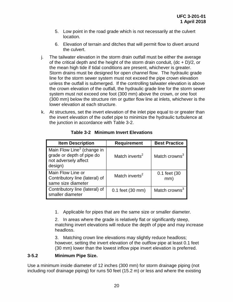
k. At structures, set the invert elevation of the inlet pipe equal to or greater than the invert elevation of the outlet pipe to minimize the hydraulic turbulence at the junction in accordance with Table 3-2.
Table 3-2 Minimum Invert Elevations
Item Description Requirement Best Practice Main Flow Line1 (change in grade or depth of pipe do not adversely affect design)
Match inverts2 Match crowns3
Main Flow Line or Contributory line (lateral) of same size diameter
Match inverts2 0.1 feet (30 mm)
Contributory line (lateral) of smaller diameter
0.1 feet (30 mm) Match crowns3
1. Applicable for pipes that are the same size or smaller diameter. 2. In areas where the grade is relatively flat or significantly steep, matching invert elevations will reduce the depth of pipe and may increase headloss. 3. Matching crown line elevations may slightly reduce headloss; however, setting the invert elevation of the outflow pipe at least 0.1 feet (30 mm) lower than the lowest inflow pipe invert elevation is preferred.
3-5.2 Minimum Pipe Size.
Use a minimum inside diameter of 12 inches (300 mm) for storm drainage piping (not including roof drainage piping) for runs 50 feet (15.2 m) or less and where the existing

UFC 3-201-01 1 April 2018
21
downstream pipe is a 12-inch (300 mm) inside diameter with sufficient capacity; otherwise, use a minimum inside diameter of 15 inches (375 mm).
3-5.3 Minimum and Maximum Cover.
Use the paragraphs below as applicable or perform calculations to determine minimum and maximum cover, pipe material, pipe strength, and bedding requirements to accommodate the imposed dead and live loads during and after construction for all pipes. Minimum and maximum cover tables, for selected pipe material, may be used for single barrel applications with equivalent shapes and loadings. Refer to Chapter 9 of AC 150/5320-5 for additional design guidance on minimum and maximum cover.
3-5.3.1 Minimum Cover.
For single barrel applications where the live load does not exceed H-20 Highway loading the minimum cover must not be less than 24 inches (600 mm), ½ of the pipe diameter, or greater than frost penetration according to UFC 3-301-01; whichever is greater. Account for loads from expected maintenance equipment in non-paved areas.
For pipe under a minimum 6 inch (150 mm) rigid pavement section, minimum cover may be reduced to 12 inches (300 mm) from the top of pipe to the finished grade if:
a. Single barrel application. b. Live load does not exceed H-20. c. ASTM C76, Class V reinforced concrete pipe is used. d. Design assumptions and calculations are approved by the Government Civil
Engineer. 3-5.3.1.1 Airfields.
Use Tables 9-9 included in Chapter 9 of AC 150/5320-5 as applicable or determine minimum cover based on project specific loads and conditions.
3-5.3.2 Maximum Cover.
Use Tables 9-1 through 9-7 in Chapter 9 of AC 150/5320-5 as applicable or determine maximum cover based project specific loads and conditions.
3-5.4 Design Velocity.
Provide a minimum full flow velocity as indicated in Table 3-3. Determine full flow velocity using the Manning equation, without surcharge.
Table 3-3 Design Velocity
Item Description Requirement Best Practice Full Flow Velocity Min. 2.5 ft/sec
(0.76 m/sec) Min. 3 ft/sec (0.91 m/sec)

UFC 3-201-01 1 April 2018
22
For storm drain system constructability, a minimum slope of 0.2 percent is recommended. The minimum full flow velocity requirement must be met regardless of the pipe slope.
3-5.5 Manning’s Roughness Coefficient.
Use Manning’s roughness coefficient, “n” of 0.013 for smooth concrete pipe. For other drainage materials see state or local regulatory agency’s requirement.
3-5.6 Material Selection.
Provide storm drain system materials in conformance with the UFGS to meet specific site conditions and soil characteristics. Consider thermal expansion of pipe material based on pipe location and temperatures of stormwater.
3-5.7 Culverts and Outfalls.
Culverts and outfalls must have headwalls, endwalls, wingwalls, flared end sections, or mitered end sections at free outlets. In areas of seasonal freezing, the structure must also be designed to preclude detrimental heave or lateral displacement caused by frost action. The most satisfactory method of preventing such damage is to restrict frost penetration beneath and behind the wall to non-frost-susceptible materials. Positive drainage behind the wall is also essential. Outlets and endwalls must be protected against undermining, bottom scour, damaging lateral erosion, and degradation of the downstream channel.
3-5.7.1 Security and Storm Drainage System Components.
Provide security barriers at all locations where security fences must cross drainage ditches or swales to ensure that intruders are prevented from passing under the fence. Use protective measures for pipes crossing under security fences with diameters larger than 10 inches (250 mm).
3-5.8 Storm Structures.
Storm structures for roads and site drainage must be in accordance with the UFGS, state DOT standards and specifications where the project is located or the requirements of the applicable local regulatory agency that governs stormwater management, whichever is more stringent. Structures must provide access for maintenance. Internal dimensions must not be less than 2 feet (0.6 m) in any one direction. Ensure that catch basins, curb inlets, and manholes are of adequate size to accommodate inlet and outlet pipes.
Provide structures of cast-in-place or precast concrete. Masonry structures are allowed for shallow installations less than 5 feet (1.5 m) in depth. Design structure frames, covers and grates to withstand traffic loadings and meet any additional requirements set forth in the using agency criteria for the particular application. Select grate type based on such factors as hydraulic efficiency, debris handling characteristics, pedestrian and

UFC 3-201-01 1 April 2018
23
bicycle safety, and loading conditions. Grates in traffic areas must be able to withstand traffic loads.
3-5.8.1 Airfields.
Use frames, covers, and grates capable of withstanding airfield traffic loadings and meeting any additional requirements set forth in the using agency’s criteria. Isolate airfield structures from the pavement section. Provide structures of cast-in-place or precast concrete; do not use masonry structures in airfield construction. Watertight joints are recommended under airfield pavements.
Use ductile iron or steel frames, grates and covers. Frames, grates, and covers must be designed to withstand maximum aircraft wheel loads, considering the gear configuration, of the largest aircraft using or expected to use the facility. Provide hold-down devices to prevent grate displacement by aircraft traffic. Commercially manufactured frames and grates that have been designed specifically for aircraft loads may be used. When manufactured grates are used, the manufacturer must certify the design load capacity of each type of structure.
3-5.8.1.1 Diagonal Routes.
For structures that will be required to support both in-line and directional traffic lanes such as diagonal taxiways or apron taxi routes, do not consider load transfer at expansion joints in the design process; however, if specific knowledge about the long-term load transfer characteristics of a particular feature supports the use of load transfer in the design of a particular drainage structure, then an exception can be allowed and load transfer considered.
3-6 STORMWATER MANAGEMENT FACILITIES.
Design stormwater management facilities in accordance with the criteria referenced in the paragraph titled, “Design Criteria” in Chapter 3. The selected approach must conform to applicable stormwater management agreements.
3-6.1 Safety And Storm Drainage System Components.
Provide protective measures for stormwater management facilities, (e.g., detention or retention ponds) in residential housing areas and other areas frequented by children in accordance with the applicable requirements of the locality, State or Host Nation equivalent. Protective measures include but are not limited to appropriate site selection for the storm water management facility or providing a fenced enclosure surrounding the facility. When provided, fence must be at a minimum 4 feet (1.2 m) high with locking access gates.
3-6.2 Airfields.
Avoid stormwater management facilities with surface storage that attract wildlife to the facility; avoid a BASH issue.

UFC 3-201-01 1 April 2018
24
3-7 STORMWATER PUMP STATIONS.
Use of stormwater pump stations is not allowed except with explicit authorization by the Government. Design stormwater pump stations in accordance with UFC 3-240-01 and WEF MF2004; whichever is more stringent. Use Best Practices document, Pumping Station Design for guidance.
3-7.1 Existing Pump Stations: Upgrades and Additional Flow.
Existing pump stations may be upgraded where a complete hydraulic analysis shows that the upgraded pump station can operate at the new capacity and in conformance with the jurisdictional requirements. Include effects on the existing force main to its point of discharge in the hydraulic analysis, and if networked, the effects on all other pump stations connected to the system. This analysis is required whenever additional flow is added to a pump station, even if physical changes to the station are not proposed.
UFC 3-201-01 1 April 2018
25
CHAPTER 4 PAVEMENTS
4-1 SURFACED AND UNSURFACED ROADS AND SITE PAVEMENTS.
Provide geometric design of vehicular roads in accordance with Chapter 2 of this UFC. Unless specified otherwise in project specific requirements, design pavement based upon anticipated vehicles and loadings for a 25 year life; however, sections shall not be less than the minimums indicated below. Use pavement design criteria and procedures recognized by the DOT in the state in which the project is located or UFC 3-250-01. When state design criteria and procedures are used, the entire pavement section must conform in every detail to the applicable state criteria and materials must conform to the DOT material specifications.
Use UFC 3-250-01 for design of airfield pavements, roads, and parking areas trafficked by special military vehicles and in areas outside of the United States. Special military vehicles include, but are not limited to: cranes, aircraft tow tractors, forklifts, container handling vehicles, tracked vehicles, heavy military cargo trucks (greater than 10,000 pounds (4535 kg) (e.g., Heavy Expanded Mobility Tactical Truck (HEMTT), Heavy Equipment Transport Systems (HETS), Palletized Load Systems (i.e. M1074, M1075), Mine-Resistant Ambush Protected (MRAP), and Stryker vehicles.
4-1.1 Frost Conditions.
The design must address seasonal frost conditions per State DOT. For overseas locations or locations where the State DOT does not address seasonal frost conditions use UFC 3-250-01.
4-1.2 Recycled Materials.
Limit recycled materials to limits in applicable UFGS sections. Recycled concrete and recycled asphalt affected by Alkali-Silica Reaction (ASR) must not be used as subbase or base course materials.
4-1.3 Flexible Pavements.
The minimum thickness of the flexible pavement section for roads and parking areas is 6 inches (150 mm). The minimum thickness of the surface course is 2 inches (50mm).
4-1.3.1 Base and Subbase Courses.
Provide a minimum thickness of granular base of 4 inches (100 mm). Provide a thicker aggregate base or subbase(s) if required to protect weak subgrade soils or to reduce frost penetration into the subgrade.
4-1.4 Rigid Pavements.
The minimum flexural strength for portland cement concrete pavements at 28 days is 650 psi (4.48 MPa). No reduction in thickness will be allowed for increased flexural strength. The minimum compressive strength for portland cement concrete sidewalks,

UFC 3-201-01 1 April 2018
26
curbs, and gutters is 3500 psi (25 MPa). Provide air entrainment in all exterior concrete pavements in areas subject to freezing temperatures. Use plain (non-reinforced) concrete for rigid pavements for roads and parking areas at military installations; use reinforced concrete for odd-shaped slabs or mismatched joints. An odd-shaped slab has a length to width ratio greater than 1.25:1. Clearly indicate on the drawings the specific individual slabs requiring reinforcement.
During design evaluate the potential for ASR and specify requirements for aggregates and cementitious materials to mitigate the possibility of ASR occurring in the concrete job mix formula for the project.
4-1.4.1 Concrete Pavement.
4-1.4.1.1 Plain Concrete.
The minimum thickness of plain concrete for roads and parking areas is 6 inches (150 mm).
4-1.4.2 Joints.
Provide joints in a manner to form a regular rectangular pattern and to prevent random or uncontrolled cracking. Do not allow the use of insertable forms for contraction joints. The use of keyed joints are discouraged, but may be used subject to evaluation of subgrade strength, loadings, pavement thickness, and details in UFC 3-250-01 and UFC 3-250-04. Dowels and tie-bars shall not be placed closer than 0.6 times the dowel or tie-bar length from the planned joint line.
4-1.5 Permeable Pavements.
Permeable pavements (such as permeable interlocking concrete pavers or pervious portland cement concrete) may be used on site pavements, such as parking lots, provided there is documented evidence of successful past performance for similar applications. Provide signage to indicate salting and sanding is not allowed for pervious portland cement concrete. Permeable pavements may not be used in areas where there is the potential to contaminate existing soils, such as fuel areas, industrial storage, marinas, vehicle maintenance or service areas. Porous asphalt pavement is not allowed. Compacted gravel is not considered permeable pavement.
Use Best Practices documents, Permeable Interlocking Concrete Pavements Manual - Design, Specification, Construction, Maintenance, from the Interlocking Concrete Pavement Institute (ICPI) and ACI 522R for additional design guidance.
4-1.6 Aggregate Pavements.
Minimum thickness for aggregate surfaced roads and parking areas is 8 inches (200 mm).

UFC 3-201-01 1 April 2018
27
4-2 AIRFIELD PAVEMENTS AND MARKINGS.
Use UFC 3-260-01 and UFC 3-260-02. Key joints for rigid pavements are not allowed for airfields.

UFC 3-201-01 1 April 2018
28
This Page Intentionally Left Blank

UFC 3-201-01 1 April 2018
29
APPENDIX A REFERENCES
AMERICAN ASSOCIATION OF STATE HIGHWAY AND TRANSPORTATION OFFICIALS
http://www.transportation.org
AASHTO GDHS, A Policy on Geometric Design of Highways and Streets
AASHTO RSDG-4, Roadside Design Guide
AASHTO HB, Standard Specifications for Highway Bridges
AMERICAN CONCRETE INSTITUTE
http://www.concrete.org
ACI 522R, Report on Pervious Concrete
AMERICAN SOCIETY OF CIVIL ENGINEERS
ASCE 24-14, Flood Resistant Design and Construction
DEPARTMENT OF THE ARMY
https://www.sddc.army.mil/sites/
DEPARTMENT OF DEFENSE Issuances
http://www.wbdg.org/ccb/browse_cat.php?o=29&c=76
DoDI 4715.05, Overseas Environmental Baseline Guidance Document
DEPARTMENT OF DEFENSE, UNIFIED FACILITIES CRITERIA PROGRAM
http://www.wbdg.org/
Consult active UFCs for all aspects of design, including but not limited to:
UFC 1-200-01, DoD Building Code (General Building Requirements)
UFC 2-100-01, Installation Master Planning
UFC 3-101-01, Architecture
UFC 3-210-10, Low Impact Development
UFC 3-220-01, Geotechnical Engineering
UFC 3-230-01, Water Storage, Distribution, and Transmission
UFC 3-201-01 1 April 2018
30
UFC 3-230-03, Water Treatment
UFC 3-240-01, Wastewater Collection
UFC 3-240-02, Domestic Wastewater Treatment
UFC 3-250-01, Pavement Design for Roads and Parking Areas
UFC 3-250-04, Standard Practice for Concrete Pavements
UFC 3-260-01, Airfield and Heliport Planning and Design
UFC 3-260-02, Pavement Design for Airfields
UFC 3-301-01, Structural Engineering
UFC 3-460-01, Design: Petroleum Fuel Facilities
UFC 3-530-01, Interior and Exterior Lighting Systems and Controls
UFC 3-600-01, Fire Protection Engineering for Facilities
UFC 4-022-01, Security Engineering: Entry Control Facilities/Access Control Points
UFC 4-022-02, Selection and Application of Vehicle Barriers
UFC 4-860-01FA, Railroad Design and Rehabilitation
DEPARTMENT OF TRANSPORTATION, FEDERAL AVIATION ADMINISTRATION (FAA)
https://www.faa.gov/regulations_policies/advisory_circulars/
AC 150/5320-5, Airport Drainage Design1
1 Requirement for Airfield Drainage criteria
UFC 3-201-01 1 April 2018
31
DEPARTMENT OF TRANSPORTATION, FEDERAL HIGHWAY ADMINISTRATION (FHWA)
https://www.fhwa.dot.gov/engineering/hydraulics/library_listing.cfm
HDS-5, Hydraulic Design of Highway Culverts
https://mutcd.fhwa.dot.gov/ser-pubs.htm
MUTCD, Manual on Uniform Traffic Control Devices
SHSM, Standard Highway Signs and Markings
EXECUTIVE ORDERS
EO 11988, Floodplain Management (May 24 1977), 42 FR 26951, 3 CFR, 1977
EO 11990, Protection of Wetlands (May 24 1977), 42 FR 26961, 3 CFR, 1977
NATIONAL OCEANIC AND ATMOSPHERIC ADMINISTRATION, FEDERAL GEODETIC CONTROL COMMITTEE (FGCC)
https://www.ngs.noaa.gov/PUBS_LIB/pub_index.html
Standards and Specifications for Geodetic Control Networks
INTERNATIONAL CODE COUNCIL (ICC)
http://www.iccsafe.org
IBC, International Building Code
IPC, International Plumbing Code
NATIONAL SOCIETY OF PROFESSIONAL SURVEYORS (NSPS)
http://www.nsps.us.com/
Model Standards for Topographic Surveys
INSTITUTE OF TRANSPORTATION ENGINEERS
www.ite.org
ITE LP-674B, Highway Capacity Manual

UFC 3-201-01 1 April 2018
32
UNITED STATES DEPARTMENT OF AGRICULTURE, NATURAL RESOURCES CONSERVATION SERVICE
http://www.wcc.ncrs.usda.gov
TR-55, Urban Hydrology for Small Watersheds
WATER ENVIRONMENT FEDERATION (WEF)
http://www.wef.org
WEF MF2004, Design of Wastewater and Stormwater Pumping Stations - MOP FD-4

UFC 3-201-01 1 April 2018
33
APPENDIX B BEST PRACTICES
This appendix identifies background information and practices for accomplishing certain civil design and engineering services. The Designer of Record (DoR) is expected to review and interpret this guidance and apply the information according to the needs of the project. If a Best Practices document has guidelines or requirements that differ from the UFGS or UFC, the UFGS and the UFC must prevail. If a Best Practices document has guidelines or requirements that are not discussed in the UFGS or UFC, the DoR must submit a list of the guidelines or requirements being used for the project with sufficient documentation to the Government Civil Engineer for review and approval prior to completing design.
B-1 WHOLE BUILDING DESIGN GUIDE.
The Whole Building Design Guide (WBDG) (www.wbdg.org) provides additional information and discussion on practice and facility design, including a holistic approach to integrated design of facilities.
The WBDG provides access to Construction Criteria Base (CCB) criteria, standards, and codes for the DoD Military Departments, National Aeronautics and Space Administration (NASA), and others. These include, UFC, UFGS, Performance Technical Specifications (PTS), design manuals, and specifications. For approved Government employees, it also provides access to non-government standards.
B-2 BEST PRACTICES CIVIL ENGINEERING RELATED GUIDANCE.
B-2.1 Building Location and Orientation.
Consider the following in regards to spacing between buildings:
a. Functional relationships. b. Operational efficiency. c. Future expansion. d. Open space – passive and active.
A building’s relationships to its support facilities and to other primary facilities influence its location. Proximity to access roads, existing utility lines, and other compatible functions (especially if they share facilities or have interdependent activities) also influence location. When a building is a shared facility, it should be centrally located and within a reasonable distance from all participating users. Buildings which depend upon a shared facility should orient either the front building face or a doorway area towards the shared facility.
UFC 3-201-01 1 April 2018
34
B-2.2 Flood Hazard Areas.
EO 11988 establishes key terms, sets the 100-year flood as the minimum building requirement and identifies floodplain management concepts. DoD Policy on Floodplain Management on Department of Defense Installations reinforces EO 11988 and establishes additional requirements for DoD projects. DoD Policy requirements include:
a. Minimizing construction within designated 100-year floodplains consistent with EO 11988; b. Document on Department of Defense Form 1391 that flood mitigation measures will be incorporated in the project when mission needs require constructing within the 100-year floodplain; c. For renovations costing more than $7.5 million to facilities already located within the 100-year floodplain, assess the vulnerability of mechanical and electrical subsystems to flood hazards and take necessary measures within major renovation projects to mitigate those vulnerabilities; and d. Annually certify, at the Assistant Secretary-level (or Director-level for Defense Agencies), that the appropriate flood damage vulnerability assessment has been completed for:
1. those military construction (MILCON) projects in the Component's budget estimate submission (BES) that will be sited within the I 00-year floodplain; and 2. those restoration and modernization (R&M) projects in facilities located within the 100-year floodplain undertaken or planned within a given fiscal year whose cost exceeds $7.5 million.
UFC 1-200-01 adopts the IBC as the DoD building code, identifies Core UFC documents and identifies unique military criteria. The IBC sets minimum requirements for buildings located in flood hazard areas including the adoption of ASCE 24. FEMA flood hazard maps and ASCE 24 are used to determine minimum building requirements in flood hazard areas. In accordance with the DoD policy, UFC 1-200-01 has lower dollar threshold than the IBC for implementing flood resistant building requirements when repairing or renovating an existing building.
B-2.3 Flood Protection Systems.
In addition to 44 CFR 65.10, considered other design criteria for design of levees and floodwalls. At a minimum, include soil types (e.g., seepage, scour and erosion), structure type, embankment stability, foundation stability, settlement, and interior drainage. Levee and floodwall systems may include active and passive components such as gates, barriers and movable walls that would need to be closed prior to a flood. When addressing operation plans include appropriate warning systems and test in place. Best Practice documents may include EM 1110-2-1913, EM 1110-2-2104, EM 1110-2-2502, EM 1110-1-1904, EM 1110-2-2504, EC 1110-2-6066, ETL 1110-2-583, EM 1110-2-1619, ER 1105-2-101, ER 1110-2-1150, and ETL 1110-2-299.
UFC 3-201-01 1 April 2018
35
B-2.3.1 Buildings and Structures.
Based on an individual site analysis, it may be more advantageous to protect a facility or a group of facilities, especially a critical facility, with a flood protection system. Flood protection systems meeting the minimum design requirements in 44 CFR 65.10 are accredited by FEMA for protection against the 1% annual chance flood. ASCE 24 requires flood protection systems to be shown on the community’s flood hazard map prior to being considered as providing adequate protection.
B-2.3.2 Roads.
Roads and similar infrastructure do not need to be designed to the same standard as buildings and structures. An engineering analysis should be conducted to determine the design flood elevation.
B-2.4 Vehicle Circulation.
Consider bicycle lanes and pedestrian corridors to reduce vehicle traffic.
B-2.4.1 Access and Service Drives.
Consider the following in locating access drives:
a. Spacing. b. Corner Clearances. c. Sight Distances. d. Left Turns. e. Entrances. f. Grading and Drainage. g. Traffic Controls.
When a safe sight distance cannot be met, consider the following alternatives:
a. Removal of sight obstructions. b. Relocation of the access drive to a more favorable location along the access
road or an alternate access road. c. Prohibition of critical movements at the access drive.

UFC 3-201-01 1 April 2018
36
B-2.5 Parking Areas.
Where slopes are steep consider providing more than one level of parking.
Table B-1 Parking Space Guidelines for Non-Organizational Vehicles
Facility Number of Parking Spaces Administration, Headquarters, and Office Buildings
60 percent of assigned personnel
Bakeries 75 percent of civilian employees, largest shift
Bank and Credit Union, when not included in a Community Shopping Center
2 percent of authorized customers served
Cafeteria, Civilian, when not included in a Community Shopping Center
15 percent of seating capacity
Central Food Preparation Facilities 38 percent of military and civilian food service operating personnel, largest shift
Chapels 30 percent of seating capacity Child Development Centers 10 percent of children, 80 percent of staff Commissary Stores, Food Sales, when not included in a Community Shopping Center
Contact DeCA for parking requirements
Community Shopping Center, including such elements as Main Exchange, Miscellaneous Shops, Restaurant, Commissary Stores, Food Sales, Bank, Theater, Post Office
4 percent of authorized customers served
Dormitories 70% of design capacity
Enlisted Personnel Dining Facilities
38 percent of military and civilian food service operating personnel, largest shift, plus 8 percent of enlisted personnel (patron parking) to be served during a meal period
Exchanges, Main, when not included in a Community Shopping Center
25 percent of authorized customers served
Family Housing 2.5 spaces per living unit Field House, combined with Football and Baseball Facilities
1 percent of military strength
Fire Stations 100% of positions per shift Guard Houses, Brigs, Military Police Stations
30 percent of guard and staff strength
Fitness Center Total parking shall not exceed 1 percent of military strength served

UFC 3-201-01 1 April 2018
37
Facility Number of Parking Spaces
Laundries and Dry Cleaning Plants 38 percent of civilian employees, largest shift
Central Libraries 1 space for each 500 ft2 (46.5 m2) gross area of floor area
Branch Libraries 8 spaces
Maintenance Shops 40 percent of assigned personnel, largest shift
Medical Facilities See UFC 4-510-01 Officers’ Quarters 100% of living suites
Schools, Dependent
Without Auditorium
With Auditorium
2 spaces per classroom
2 spaces per classroom, plus 15 percent of auditorium seats
Security Offices (at gates) for military installations of:
100 to 2,000 population
2,001 to 4,000 population
4,001 to 6,000 population
6,001 to 10,000 population
10,001 and over
5 spaces
10 spaces
15 spaces
20 spaces
To be based on a special study.
Service Clubs 2 percent of enlisted personnel or officer strength served
Swimming Pools 20 percent of design capacity of the swimming pool
Temporary Lodging Facilities 90 percent of bedrooms Theaters, when not included in a Community Shopping Center
25 percent of seating capacity
Warehouses 1 space for each 500 ft2 [46.5 m2] gross area of office area, plus one space for 4 persons assigned to storage activities

UFC 3-201-01 1 April 2018
38
B-2.5.2 On-Street Parking.
Consider the width of the travel lane and the types of vehicles. A parking lane width of 10 feet (3.0 m) to 12 feet (3.6 m) is recommended for delivery vehicles.
B-2.5.3 Off-Street Parking.
Consider the following in the parking lot design: a. Maintain two-way movement. b. Avoid dead end parking lots. c. Provide cross aisles every 20 to 30 spaces.
d. Provide curbs or painted lines at the ends of stalls to control placement of vehicles. e. Provide adequate walkway width to allow comfortable pedestrian movement in areas of bumper overhang. f. Consider the requirements for snow removal.
B-2.5.3.1 Islands and Medians.
Locate islands at the ends of parking stalls and at the intersections of parking aisles. The islands establish turning radii for vehicular movement and protect end stalls. Consider the height of driver’s eye level when providing shrubs and small trees.
B-2.5.4 Compact Parking
The use of compact space is limited for the following reasons:
a. The potential for building function to change. b. They do not comply with accessible parking requirements. c. Compact spaces limit the amount of available parking for standard vehicles.
B-2.5.5 Motorcycle Parking.
Design considerations for motorcycle parking include:
a. Locate parking close to building entrances. b. Locate parking in parking lot corners. c. Provide signage and pavement markings.
B-2.5.6 Buffers.
Provide a 20 feet (6.1 m) wide buffer strip to separate parking areas from adjacent roads.
UFC 3-201-01 1 April 2018
39
B-2.5.7 Drop Off Areas.
Design considerations for drop-off areas include adequate width and length to accommodate the safe movement of vehicles in and out of the flow of traffic.
B-2.5.8 Delivery and Service Zones.
Delivery and service trucks need to access service doors in buildings. Delivery may require dock facilities, which need to accommodate the necessary maneuvering into and out of the dock. Design considerations for delivery zones include:
a. Separate service access drives from parking circulation because these functions are incompatible. Service access that is required through a parking area goes straight to and straight out of the service area.
e. On a dead-end service drive, provide the necessary turning movements. f. Provide for visual screening with walls, fences, or plant material.
B-2.5.8.1 Garbage Collection Areas.
The design of garbage collection removal areas (i.e., dumpster pads) is controlled by the frequency of waste removal. Coordinate with the Installation to determine the frequency of waste removal and determine appropriate dumpster pad size. Consider screening solid waste removal areas with fences, walls, or plant material in accordance with the Installation Appearance Plan.
B-2.5.9 Facilities with Drive Thru Lanes.
Facilities with one or more drive thru lanes, such as banks, pharmacies, and fast–food restaurants, require careful and clear establishment of traffic patterns and a continuous traffic flow. The standard configuration for a single – or double-service position facility does not lend itself to a two–lane approach and departure design. It usually relies on some form of loop system. Average stacking distance is recommended as 180 feet (54.8 m). Stacking space is determined by subtracting the number served (serving time averages 2-3 minutes per customer) from the expected arrivals per 15-minute period (4-14 minutes is the average) and multiplying the difference times 20 feet (6.1 m). Recommended parking for facilities with drive thru lane(s) is 17.5 spaces per 1,000 sq. feet (93.0 square meters) of building area. Design considerations for facilities with drive thru lane(s) include:
a. Maintain traffic lanes into and out of the drive thru windows while working with other on-site vehicular traffic flow including parking.
b. Minimize interference with pedestrian traffic flow. c. Provide the recommended average stacking distance in the drive-thru lanes. d. Provide the recommended average stacking distance on-site to prevent
traffic safety conflicts with access roads. e. Use curb and planting islands for vehicle control.

UFC 3-201-01 1 April 2018
40
f. Provide adequate pavement markings.
B-2.6 Rational Formula.
Use the Rational Formula to determine peak flow from small watersheds. The Rational Formula is based on the following assumptions:
a. Peak flow occurs when the entire watershed is contributing runoff. b. he rainfall intensity is uniform over a period of time equal to or greater than the time of concentration. c. The frequency of the peak flow equals the frequency of the peak rainfall intensity. For example, the 10-year peak rainfall will produce the 10-year peak flood.
These assumptions are not fully valid in every case. However, if the Rational Formula is used on small watersheds, parking lots, or small developed areas, the errors will not be large.
The most common form of the Rational Formula is:
Q = c I A where Q = peak flow in cfs.
C = a dimensionless coefficient that is a function of the watershed characteristics.
I = rainfall intensity in inches per hour.
A = watershed area in acres.
B-2.7 Airfield Pavements.
For additional guidance on design and construction of airfield pavements see IPRF-01-G-002-1 and ACPA Document No. JP007P.
B-3 BEST PRACTICE REFERENCES.
AMERICAN ASSOCIATION OF STATE HIGHWAY AND TRANSPORTATION OFFICIALS (AASHTO)
http://www.transportation.org
AASHTO GPF, Guide for the Planning, Design and Operation of Pedestrian Facilities
AASHTO VLVLR, Guidelines for Geometric Design of Very Low-Volume Local Roads (ADT ≤ 400)

UFC 3-201-01 1 April 2018
41
INNOVATIVE PAVEMENT RESEARCH FOUNDATION, AIRPORT CONCRETE PAVEMENT TECHNOLOGY PROGRAM
http://www.iprf.org
ACPA Document No. JP007P, Best Practices for Airport Portland Cement Concrete Pavement Construction
AMERICAN RAILWAY ENGINEERING AND MAINTENANCE-OF-WAY ASSOCIATION (AREMA)
http://www.arema.org
Manual for Railway Engineering (Volumes 1 and 2)
BUTTERWORTH-HEINEMANN, 30 Corporate Drive, Suite 400, Burlington, MA 01803
Pumping Station Design, edited by Garr M. Jones with Robert L. Sanks, George Tchobanoglous and Bayard Bosserman
U.S. DEPARTMENT OF AGRICULTURE, FOREST SERVICE, SAN DIMAS TECHNOLOGY AND DEVELOPMENT CENTER
https://www.fs.fed.us/t-d/pubs/
USDA 0625 1808P, Low-Water Crossings: Geomorphic, Biological, and Engineering Design Considerations
DEPARTMENT OF TRANSPORTATION, FEDERAL AVIATION ADMINISTRATION (FAA)
https://www.faa.gov/regulations_policies/advisory_circulars/
AC 150/5320-5, Airport Drainage Design2
FEDERAL EMERCENCY MANAAGEMNT AGENCY (FEMA)
https://www.fema.gov/guidelines-and-standards-flood-risk-analysis-and-mapping
FEMA GD34, Guidance for Flood Risk Analysis and Mapping
2 Best Practice for storm drainage systems other than airfields.

UFC 3-201-01 1 April 2018
42
INTERLOCKING CONCRETE PAVEMENT INSTITUTE (ICPI)
http://www.icpi.org
Permeable Interlocking Concrete Pavements Manual - Design, Specification, Construction, Maintenance
HEADQUARTERS, U.S. ARMY CORPS OF ENGINEERS (HQUSACE)
EM 1110-2-1913, Design and Construction of Levees
EM 1110-2-2104, Strength Design for Reinforced-Concrete Hydraulic Structures
EM 1110-2-2502, Retaining and Flood Walls
EM 1110-1-1904, Settlement Analysis
EM 1110-2-2504, Sheet Pile Walls
EC 1110-2-6066, Design of I-Wall
ETL 1110-2-583, Engineering and Design: Guidelines for Landscape Planting and Vegetation Management at Levees, Floodwalls, Embankment Dams, and Appurtenant Structures
EM 1110-2-1619, Risk-Based Analysis for Flood Damage Reduction Studies
ER 1105-2-101, Risk Assessment for Flood Risk Management Studies
ER 1110-2-1150, Engineering and Design for Civil Works Projects
ETL 1110-2-299, Overtopping of Flood Control Levees and Floodwalls

UFC 3-201-01 1 April 2018
43
APPENDIX C GLOSSARY
C-1 ACRONYMS
AASHTO American Association of State Highway and Transportation Officials
ADT Average Daily Traffic
AFCEC Air Force Civil Engineering Center
AIROPS Airfield Operations Bird/Animal Aircraft Strike Hazard
AREMA American Railway Engineering and Maintenance-of-Way Association
ASR Alkali-Silica Reaction
AT&L Acquisition, Technology, and Logistics
AWWA AMERICAN WATER WORKS ASSOCIATION
BASH Bird/Animal Aircraft Strike Hazard
BIA Bilateral Infrastructure Agreement
CCB Construction Criteria Base
DoD Department of Defense
DoR Designer of Record
DOT Department of Transportation
E.g. Exempli Gratia (one or more possible examples)
EISA Energy Independence and Security Act
EO Executive Order
EPA Environmental Protection Agency
FAA Federal Aviation Administration
FEMA Federal Emergency Management Agency
FHWA Federal Highway Administration
FIRM Flood Insurance Rate Map
FIS Flood Insurance Study
HEMTT Heavy Expanded Mobility Tactical Truck

UFC 3-201-01 1 April 2018
44
HETS Heavy Equipment Transport Systems
HQUSACE Headquarters, U.S. Army Corps of Engineers
HNFA Host Nation Funded Construction Agreements
IBC International Building Code
ICPI Interlocking Concrete Pavement Institute
IDF Intensity-Duration-Frequency
I.e. Id Est (clarifies, more precisely)
IPC International Plumbing Code
LID Low Impact Development
MILCON Military Construction
MRAP Mine-Resistant Ambush Protected
MUTCD Manual on Uniform Traffic Control Devices
NASA National Aeronautics and Space Administration
NAVFAC Naval Facilities Engineering Command
NEPA National Environmental Policy Act
NOAA National Oceanic and Atmospheric Administration
NSPS National Society of Professional Surveyors
OEBGD Overseas Environmental Baseline Guidance Document
PTS Performance Technical Specifications
PPV Public-Private Ventures
R&M Restoration and Modernization
SDDCTEA Surface Deployment and Distribution Command Transportation Engineering Agency
SOFA Status of Forces Agreements
TR-55 Technical Release 55
TRB Transportation Research

UFC 3-201-01 1 April 2018
45
UFC Unified Facilities Criteria
UFGS Unified Facilities Guide Specifications
U.S. United States
USDA United States Department of Agriculture
WBDG Whole Building Design Guide


![UNIFIED FACILITIES CRITERIA (UFC) DoD FACILITIES PRICING … · UFC 3-701-01 23 May 2018 Change 5, 3 February 2020 UNIFIED FACILITIES CRITERIA (UFC) [REVISION] SUMMARY SHEET Document:](https://img.dokumen.tips/doc/110x75/5ece76c4afcfdc39ce5e1035/unified-facilities-criteria-ufc-dod-facilities-pricing-ufc-3-701-01-23-may-2018.jpg)


![UNIFIED FACILITIES CRITERIA (UFC) DoD FACILITIES …UFC 3-701-01 23 May 2018 Change 7, 24 Sept 2020 UNIFIED FACILITIES CRITERIA (UFC) [REVISION] SUMMARY SHEET Document: UFC 3-701-01,](https://img.dokumen.tips/doc/110x75/600dc4754ebf336b371eab2d/unified-facilities-criteria-ufc-dod-facilities-ufc-3-701-01-23-may-2018-change.jpg)


![UNIFIED FACILITIES CRITERIA (UFC) DoD FACILITIES PRICING … · 2021. 2. 3. · UFC 3-701-01 23 May 2018 Change 8, 3 Feb 2021 UNIFIED FACILITIES CRITERIA (UFC) [REVISION] SUMMARY](https://img.dokumen.tips/doc/110x75/61486a752918e2056c22aca1/unified-facilities-criteria-ufc-dod-facilities-pricing-2021-2-3-ufc-3-701-01.jpg)