Embed Size (px)
Citation preview
UFC 3-190-03A 17 November 2003
UNIFIED FACILITIES CRITERIA (UFC)
X-RAY SHIELDING
APPROVED FOR PUBLIC RELEASE; DISTRIBUTION UNLIMITED
INACTIV
E
UFC 3-190-03A 17 November 2003
UNIFIED FACILITIES CRITERIA (UFC)
X-RAY SHIELDING
Any copyrighted material included in this UFC is identified at its point of use. Use of the copyrighted material apart from this UFC must have the permission of the copyright holder. U.S. ARMY CORPS OF ENGINEERS (Preparing Activity) NAVAL FACILITIES ENGINEERING COMMAND AIR FORCE CIVIL ENGINEER SUPPORT AGENCY Record of Changes (changes are indicated by \1\ ... /1/) Change No. Date Location
This UFC supersedes TM 5-805-12, dated January 1990. The format of this UFC does not conform to UFC 1-300-01; however, the format will be adjusted to conform at the next revision. The body of this UFC is the previous TM 5-805-12, dated January 1990.
INACTIV
E
UFC 3-190-03A 17 November 2003
FOREWORD \1\ The Unified Facilities Criteria (UFC) system is prescribed by MIL-STD 3007 and provides planning, design, construction, sustainment, restoration, and modernization criteria, and applies to the Military Departments, the Defense Agencies, and the DoD Field Activities in accordance with USD(AT&L) Memorandum dated 29 May 2002. UFC will be used for all DoD projects and work for other customers where appropriate. All construction outside of the United States is also governed by Status of forces Agreements (SOFA), Host Nation Funded Construction Agreements (HNFA), and in some instances, Bilateral Infrastructure Agreements (BIA.) Therefore, the acquisition team must ensure compliance with the more stringent of the UFC, the SOFA, the HNFA, and the BIA, as applicable. UFC are living documents and will be periodically reviewed, updated, and made available to users as part of the Services’ responsibility for providing technical criteria for military construction. Headquarters, U.S. Army Corps of Engineers (HQUSACE), Naval Facilities Engineering Command (NAVFAC), and Air Force Civil Engineer Support Agency (AFCESA) are responsible for administration of the UFC system. Defense agencies should contact the preparing service for document interpretation and improvements. Technical content of UFC is the responsibility of the cognizant DoD working group. Recommended changes with supporting rationale should be sent to the respective service proponent office by the following electronic form: Criteria Change Request (CCR). The form is also accessible from the Internet sites listed below. UFC are effective upon issuance and are distributed only in electronic media from the following source: • Whole Building Design Guide web site http://dod.wbdg.org/. Hard copies of UFC printed from electronic media should be checked against the current electronic version prior to use to ensure that they are current. AUTHORIZED BY: ______________________________________ DONALD L. BASHAM, P.E. Chief, Engineering and Construction U.S. Army Corps of Engineers
______________________________________DR. JAMES W WRIGHT, P.E. Chief Engineer Naval Facilities Engineering Command
______________________________________ KATHLEEN I. FERGUSON, P.E. The Deputy Civil Engineer DCS/Installations & Logistics Department of the Air Force
______________________________________Dr. GET W. MOY, P.E. Director, Installations Requirements and Management Office of the Deputy Under Secretary of Defense (Installations and Environment)
INACTIV
E

TM 5-805-12
TECHNICAL MANUAL
X - R A Y S H I E L D I N G
H E A D Q U A R T E R S , D E P A R T M E N T O F T H E A R M YJANUARY 1990IN
ACTIVE

TM 5-805-12
REPRODUCTION AUTHORIZATION/RESTRICTIONS
This manual has been prepared by or for the Government and is public property and not subject to copyright.
Reprints or replications of this manual should include a credit substantially as follows:
"Department of the Army Technical manual 5-805-12, X-Ray Shielding, 8 January 1990."
INACTIV
E
TM 5-805-12
TECHNICAL MANUAL HEADQUARTERSDEPARTMENT OF THE ARMY
NO. 5-805-12 WASHINGTON, DC, 8 January 1990
X-RAY SHIELDING
Paragraph Page
Purpose ....................................................................................................................................... 1 1-1Scope .......................................................................................................................................... 2 1-1References .................................................................................................................................. 3 1-1Glossary ...................................................................................................................................... 4 1-1General recommendations .......................................................................................................... 5 1-1Assumptions................................................................................................................................ 6 1-2Shielding criteria.......................................................................................................................... 7 1-2Materials and installations ........................................................................................................... 8 1-2Lead-lined doors and accessories............................................................................................... 9 1-14Inspection .................................................................................................................................... 10 1-22Testing and certification .............................................................................................................. 11 1-24Glossary
List of Figures
Figure 1. Fastening methods...................................................................................................................... 1-72. Wallboard .................................................................................................................................... 1-83. Lath.............................................................................................................................................. 1-94. Plywood panels............................................................................................................................ 1-105. Suspended lath ceiling ................................................................................................................ 1-116. Blocks (light lead-lined) ............................................................................................................... 1-127. Blocks (heavy lead-lined) ............................................................................................................ 1-138. Floor lead..................................................................................................................................... 1-149. Lead door threshold..................................................................................................................... 1-15
10. Lead-lined doors.......................................................................................................................... 1-1611. Door hardware............................................................................................................................. 1-1712. Lead-lined control window frames............................................................................................... 1-1813. Lead-lined film transfer cabinet ................................................................................................... 1-1914. Shapes of lead-lined control screens .......................................................................................... 1-2015. Modular lead-lined control screens.............................................................................................. 1-2116. Baffle design for openings in secondary barriers ........................................................................ 1-2217. Baffle design for openings in primary barriers............................................................................. 1-2318. Lead shielding for service boxes and conduit in concrete barriers.............................................. 1-24
List of Tables
Table 1. Minimum shielding requirements for radiographic x-ray facilities................................................ 1-32. Minimum shielding requirements for fluoroscopic x-ray facilities ................................................ 1-43. Summary of shielding requirements for diagnostic x-ray facilities............................................... 1-54. Lead shielding conversions ......................................................................................................... 1-6
*This manual supersedes TM 680512, 15 October 19680.
i
INACTIV
E

TM 5-805-12
1. Purpose.This technical manual is a guide for designing, constructing, and certifying dental, diagnostic, and therapeutic radiationexposure rooms using equipment having energies up to 10 million electron volts (MeV).
2. Scope.This manual provides guidance to personnel involved in planning, designing, procuring, constructing, and certifying Armyradiation exposure rooms.
3. References.The following documents form a part of this manual to the extent referenced:
a. Army Technical Bulletin (TB): TB MED 521-Occupational and Environmental Health Management andControl of Diagnostic X-Ray, Therapeutic X-Ray, and Gamma-Beam Equipment.
b. National Council on Radiation Protection and Measurements (NCRP); 7910 Woodmont Ave., Landow Bldg,Suite 1016, Bethesda, MD 20014.
Report 33-Medical X-Ray and Gamma-Ray Protection for Energies up to 10 MeV (Equipment Design and Use).(Feb 68)
Report 35-Dental X-Ray Protection. (Mar 70) Report 49-Structural Shielding Design and Evaluation for MedicalUse of X-Rays and Gamma-Rays of Energies up to 10 MeV. (Sep 76)
Report 51-Radiation Protection Design Guidelines for 0.1-100 MeV Particle Accelerator Facilities. (1977)
4. Glossary.
The glossary contains a list of specialized words with definitions.
5. General recommendations.a. Qualification of expert. In accordance with TB MED 521, the design or modification of diagnostic x-ray,
therapeutic x-ray, or gamma-beam therapy facilities shall be undertaken only by experts certified in radiological physics ortherapeutic radio-logical physics by the American Board of Radiology or the American Board of Health Physics or thosehaving equivalent qualifications. Design contracts should require submittal of such certification along with experiencerecords.
b. Design drawings. Design drawings will be reviewed and signed by the expert before submittal to the ContractingOfficer for review. Drawings will be reviewed for compliance with proper design and shielding requirements set forth in TBMED 521 and NCRP Report 49. All designs will be evaluated by the Office of the Surgeon General (SG-FP-ZA), US ArmyHealth Facility Planning Agency, Washington, D.C. 20310 and the Health Physics Division, US Army EnvironmentalHygiene Agency (USAEHA), Aberdeen Proving Ground, MD 21010.
c. Supplied data. The following data should be made available to support the technical review.(1) Architectural information.
(a) Drawings of radiation rooms and adjacent areas; scale preferred is 1/4 inch = 1 foot, or larger.(b) Information about occupancy below, above, and adjacent to radiation rooms.(c) Type of proposed or existing construction of floors, ceilings, and walls.(d) Vertical sections and plot plans for megavoltage therapy installations, including cobalt.
(2) Equipment less the 150 kilovolts.(a) Purpose of equipment will be stated as therapy, radiography, fluoroscopy, special procedures, or
cystoscopy.(b) Kilovolts and expected weekly workload, if known.
(3) Equipment 150 kilovolts and greater, including gamma apparatus.(a) Kilovolts or type of gamma source.(b) Milliamperes or roentgens per minute at 1 meter.(c) Weekly workload, if known, expressed in Milliamperes or roentgens at 1 meter.(d) Restrictions in beam orientations without and with beam interceptor, if any.(e) Use factor for walls and ceilings, if known.(f) Leakage radiation of source housing with beam "ON."(g) Attenuation by beam interceptor, if any.(h) Possible future increases in workload and radiation energy, and modification in beam orientation.(i) Manufacturer’s electrical requirements for high voltage generators.
d. Typical designs. Typical designs are shown in TB MED 521 and NCRP Reports 49 and 51.1-1
INACTIV
E

TM 5-805-12
e. Structural details. Structural details and detailed drawings must show construction of sheet-lead barriers. Thejoining of lead materials must be designed to avoid radiation leakage and scattering. All drawings will conform to NCRPReports 35 and 49 and will become part of the design drawings. Specific drawings and specifications should be preparedto:
(1) Indicate the penetration in barriers, such as pipes, ducts, conduits, and louvers, that should be provided withbaffles.
(2) Show where and how lead is to be placed at doors, door openings, door sills, observation windows, corners,floors and ceilings, and other breaks in the lead barrier.
(3) Specify what should not be pierced by nails, screws, rivets, and bolts, without adequate provisions forequivalent cover protection.
6. Assumptions.The following assumptions should be made in determining the shielding requirements for x-ray and gammaray medicaland dental facilities referenced in TB MED 521:
a. X-ray technicians or radiologists will spend their entire work period in the controlled area.b. Areas adjacent to the radiological rooms are to be occupied by persons nonoccupationally exposed to ionizing
radiation.c. The x-ray system is operated at its maximum rated peak tube potential (kilovolt peak) and tube current
(milliamperes).d. The minimum source-to-occupied-area distance is 5 feet.e. The minimum distance from an unshielded outside wall of a radiographic room to an occupied area is at least 50
feet.f. The required thickness of the shielding depends on the quality of radiation, quantity being produced in some
chosen period of time, distance from the tube, degree and nature of occupancy, type of area, and material of which thebarrier is to be constructed.
7. Shielding criteria.Minimum shielding thicknesses will conform to the following criteria. In all other areas, shielding will be designed for thespecific environment. See tables 1, 2, 3, and 4 for general shielding information.
a. Dental rooms. Guidelines for the thicknesses of barriers (walls, ceiling, and floor) will be determined from NCRPReport 35 and TB MED 521.
(1) Shielding will cover walls and doors up to 7 feet above the floor.(2) Ceilings will be covered with lead if space above can be occupied and calculations indicate a need for
increased shielding.(3) Floors will be covered with lead if space below can be occupied and calculations indicate a need for
increased shielding.(4) Control booth or protective barrier, including observation window, will have the same rating as specified
shielding. Control booth will be arranged so that radiation has to be scattered twice before entering the protected area.The control booth will be large enough to adequately protect the controls and operator. The viewing window shall be atleast 16 by 24 inches. For standing operations, the bottom of the viewing window should be 45 inches above the floor.There shall be a minimum of 18 inches from the edge of the shield to the edge of the viewing window.
b. Diagnostic and therapy installations. Guidelines for the thicknesses of barriers (walls, ceilings, and floor) shall bedetermined from NCRP Report 49 and TB MED 521.
(1) Photofluorographic equipment uses a camera to photograph the image produced on a fluorographic screen.When the x-ray tube orientation is restricted so that the useful beam can be directed only toward the camera, a primaryprotective barrier is required only for the wall behind the camera. This primary protective barrier will extend at least 1 footbeyond the perimeter of the useful beam at the wall. All other wall, floor, and ceiling areas of photofluorographic andautomatic upright chest installations are secondary barriers and should have a lead equivalent thickness of at least 1/32inch.
(2) Floors will be covered with lead if the area below the radiography room can be occupied.(3) Ceilings will be covered with lead if the area above the radiography room can be occupied.
8. Materials and installations.Material used in protective barriers will conform to NCRP Reports 35 and 49. Lead is generally used as a shieldingmaterial in facilities using x-ray potentials of 300 kilovolts and less. For higher voltages, standard concrete (140 to 160 lb-ft3), Hi-Density concrete (190 to 340 lb-ft3) and earth are normally used. Lead sheets of different thicknesses can be
1-2
INACTIV
E
TM 5-805-12
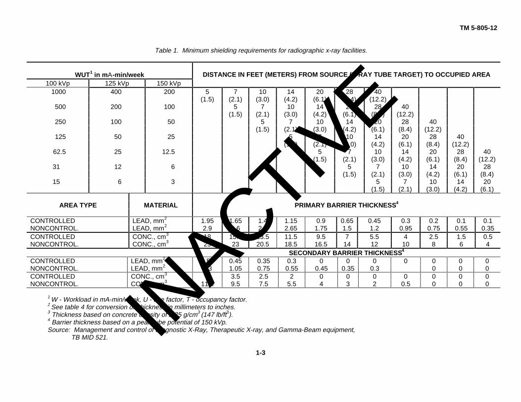
Table 1. Minimum shielding requirements for radiographic x-ray facilities.
WUT1 in mΑ-min/week DISTANCE IN FEET (METERS) FROM SOURCE (X-RAY TUBE TARGET) TO OCCUPIED AREA100 kVp 125 kVp 150 kVp
1000 400 200 5 7 10 14 20 28 40(1.5) (2.1) (3.0) (4.2) (6.1) (8.4) (12.2)
500 200 100 5 7 10 14 20 28 40(1.5) (2.1) (3.0) (4.2) (6.1) (8.4) (12.2)
250 100 50 5 7 10 14 20 28 40(1.5) (2.1) (3.0) (4.2) (6.1) (8.4) (12.2)
125 50 25 5 7 10 14 20 28 40(1.5) (2.1) (3.0) (4.2) (6.1) (8.4) (12.2)
62.5 25 12.5 5 7 10 14 20 28 40(1.5) (2.1) (3.0) (4.2) (6.1) (8.4) (12.2)
31 12 6 5 7 10 14 20 28(1.5) (2.1) (3.0) (4.2) (6.1) (8.4)
15 6 3 5 7 10 14 20(1.5) (2.1) (3.0) (4.2) (6.1)
AREA TYPE MATERIAL PRIMARY BARRIER THICKNESS4
CONTROLLED LEAD, mm2 1.95 1.65 1.4 1.15 0.9 0.65 0.45 0.3 0.2 0.1 0.1NONCONTROL. LEAD, mm2 2.9 2.6 2.3 2.65 1.75 1.5 1.2 0.95 0.75 0.55 0.35CONTROLLED CONC., cm3 18 15.5 13.5 11.5 9.5 7 5.5 4 2.5 1.5 0.5NONCONTROL. CONC., cm3 25 23 20.5 18.5 16.5 14 12 10 8 6 4
SECONDARY BARRIER THICKNESS4
CONTROLLED LEAD, mm2 0.55 0.45 0.35 0.3 0 0 0 0 0 0 0NONCONTROL. LEAD, mm2 1.3 1.05 0.75 0.55 0.45 0.35 0.3 0 0 0CONTROLLED CONC., cm3 5 3.5 2.5 2 0 0 0 0 0 0 0NONCONTROL. CONC., cm3 11.5 9.5 7.5 5.5 4 3 2 0.5 0 0 0
1 W - Workload in mA-min/week, U - use factor, T - occupancy factor.2 See table 4 for conversion of thickness in millimeters to inches.3 Thickness based on concrete density of 2.35 g/cm3 (147 lb/ft3).4 Barrier thickness based on a peak tube potential of 150 kVp.Source: Management and control of Diagnostic X-Ray, Therapeutic X-ray, and Gamma-Beam equipment,
TB MID 521.
1-3IN
ACTIVE
TM 5-805-12
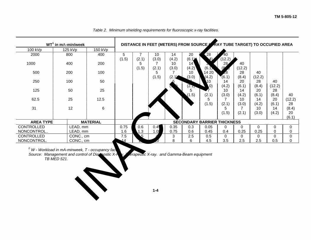
Table 2. Minimum shielding requirements for fluoroscopic x-ray facilities.
WT1 in mΑ-min/week DISTANCE IN FEET (METERS) FROM SOURCE (X-RAY TUBE TARGET) TO OCCUPIED AREA100 kVp 125 kVp 150 kVp
2000 800 400 5 7 10 14 20 28 40(1.5) (2.1) (3.0) (4.2) (6.1) (8.4) (12.2)
1000 400 200 5 7 10 14 20 28 40(1.5) (2.1) (3.0) (4.2) (6.1) (8.4) (12.2)
500 200 100 5 7 10 14 20 28 28 40(1.5) (2.1) (3.0) (4.2) (6.1) (8.4) (12.2)
250 100 50 5 7 10 14 20 28 40(1.5) (2.1) (3.0) (4.2) (6.1) (8.4) (12.2)
125 50 25 5 7 10 14 20 28(1.5) (2.1) (3.0) (4.2) (6.1) (8.4) 40
62.5 25 12.5 5 7 10 14 20 (12.2)(1.5) (2.1) (3.0) (4.2) (6.1) 28
31 12 6 5 7 10 14 (8.4)(1.5) (2.1) (3.0) (4.2) 20
(6.1)AREA TYPE MATERIAL SECONDARY BARRIER THICKNESS
CONTROLLED LEAD, mm 0.75 0.6 0.45 0.35 0.3 0.05 0 0 0 0 0NONCONTROL.. LEAD, mm 1.6 1.3 1.05 0.75 0.6 0.45 0.4 0.25 0.25 0 0CONTROLLED CONC., cm 7.5 5.5 4 3 2.5 0.5 0 0 0 0 0NONCONTROL. CONC., cm 14 12 10 8 6 4.5 3.5 2.5 2.5 0.5 0
0 W - Workload in mA-minweek, T - occupancy factor.Source: Management and control of Diagnostic X-Ray. Therapeutic X-ray. and Gamma-Beam equipment
TB MED 521.
1-4INACTIV
E
TM 5-805-12
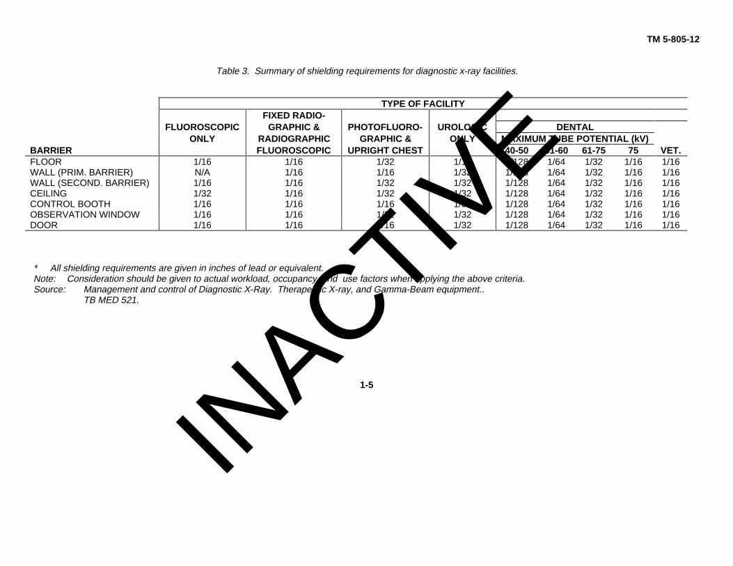
Table 3. Summary of shielding requirements for diagnostic x-ray facilities.
TYPE OF FACILITYFIXED RADIO-
FLUOROSCOPIC GRAPHIC & PHOTOFLUORO- UROLOGIC DENTALONLY RADIOGRAPHIC GRAPHIC & ONLY MAXIMUM TUBE POTENTIAL (kV)
BARRIER FLUOROSCOPIC UPRIGHT CHEST 40-50 51-60 61-75 75 VET.FLOOR 1/16 1/16 1/32 1/16 1/128 1/64 1/32 1/16 1/16WALL (PRIM. BARRIER) N/A 1/16 1/16 1/32 1/128 1/64 1/32 1/16 1/16WALL (SECOND. BARRIER) 1/16 1/16 1/32 1/32 1/128 1/64 1/32 1/16 1/16CEILING 1/32 1/16 1/32 1/32 1/128 1/64 1/32 1/16 1/16CONTROL BOOTH 1/16 1/16 1/16 1/32 1/128 1/64 1/32 1/16 1/16OBSERVATION WINDOW 1/16 1/16 1/32 1/32 1/128 1/64 1/32 1/16 1/16DOOR 1/16 1/16 1/16 1/32 1/128 1/64 1/32 1/16 1/16
* All shielding requirements are given in inches of lead or equivalent.Note: Consideration should be given to actual workload, occupancy, and use factors when applying the above criteria.Source: Management and control of Diagnostic X-Ray. Therapeutic X-ray, and Gamma-Beam equipment..
TB MED 521.
1-5
INACTIV
E

TM 5-805-12
Table 4. Lead shielding conversions.
THICKNESSAPPROXIMATE WEIGHT
MILLIMETERS INCHES DECIMAL INCHES POUND/FT 3
0.20 1/128 0.0078 0.50.40 1/64 0.0158 1.00.60 3/128 0.0234 1.50.79 1/32 0.0313 2.01.00 5/128 0.0391 2.51.19 3/64 0.0469 3.01.39 7/128 0.0547 3.51.58 1/16 0.0625 4.01.98 5/64 0.0781 5.O2.38 3/82 0.0938 6.03.17 1/8 0.1250 8.03.97 5/32 0.1563 10.04.76 3/18 0.1875 12.05.56 7/32 0.2187 14.06.35 1/4 0.2500 16.07.14 9/32 0.2813 16.57.94 5/16 0.3125 18.08.47 1/3 0.3333 20.08.73 11/32 0.3834 20.59.53 3 0.3750 22.0
10.76 2/5 0.4000 24.011.11 7/16 0.4375 26.012.70 1/2 0.5000 30.014.29 /16 0.5625 33.015.88 5/8 0.6250 37.016.93 2/3 0.6667 40.017.46 11/16 0.6875 41.019.05 3/4 0.7500 45.020.64 13/16 0.8125 48.022.23 7/8 0.8750 52.023.81 15/16 0.9375 55.025.40 1 1.000 60.0
Source: Management and control of Diagnostic X-Ray, Therapeutic X-Ray, and Gamma-Beam equipment, TB MED 521.
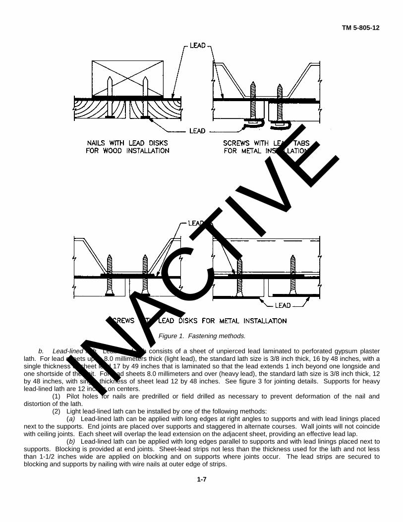
bonded under pressure to plywood, gypsum plaster lath, gypsum wall board, aluminum, or steel. Lead panels can befastened with common nails or common screws that are covered with a lead tab, grommet, and/or a lead disk dependingon whether the studs or furring strips are wood or metal. See figure 1 for details.
a. Lead-lined wallboard. Lead-lined wallboard consists of a sheet of unpierced lead laminated to gypsumwallboard. The standard wallboard size is 1/2 or 5/8 inch thick, 48 inches wide, and 96 inches long. See figure 2 forjointing details.
(1) Pilot holes for lead-headed nails are predrilled or field drilled as necessary to prevent deformation of thelead-headed nail and distortion of the wallboard.
(2) Wallboard is applied with long edges parallel to supports and with lead linings placed next to supports.Blocking is provided at end joints. Sheet-lead strips not less than the thickness used on the wallboard and not less than 1-1/2 inches wide are installed on blocking and supports where joints occur. The lead strips are secured to blocking andsupports with wire nails at outer edges of strips. Edges of the wallboard are butt-jointed and nailed to supports with nailsat approximately 8 inches on centers at joints and 12 inches on centers at intermediate supports. The nails are drivenslightly below the surface of the wallboard and then covered with a 5/16-inch diameter lead disk. Lead disks are coveredby tape or spackling to hold them in place.
(3) When using screws to attach wallboard to metal studs, they must be 1 inch long and used at the edges ofthe board. Heads of screws are covered with a 1/2-inch diameter lead disc cemented to wallboard and made flush withthe surface of the wallboard.
(4) When using two layers of wallboard, the finish ply is to be bonded to the first ply with a laminating adhesivethat is applied following the manufacturer’s recommendations. First ply of wallboard is nailed to supports with a nailcovered with a 5/8-inch diameter lead disk. Nailing of the finish ply will not be permitted. A shoring system will be used tohold the finish ply in place until the adhesive dries; a minimum of 24 hours.
1-6
INACTIV
E
TM 5-805-12
Figure 1. Fastening methods.
b. Lead-lined lath. Lead-lined lath consists of a sheet of unpierced lead laminated to perforated gypsum plasterlath. For lead sheets up to 8.0 millimeters thick (light lead), the standard lath size is 3/8 inch thick, 16 by 48 inches, with asingle thickness of sheet lead 17 by 49 inches that is laminated so that the lead extends 1 inch beyond one longside andone shortside of the unit. For lead sheets 8.0 millimeters and over (heavy lead), the standard lath size is 3/8 inch thick, 12by 48 inches, with single thickness of sheet lead 12 by 48 inches. See figure 3 for jointing details. Supports for heavylead-lined lath are 12 inches on centers.
(1) Pilot holes for nails are predrilled or field drilled as necessary to prevent deformation of the nail anddistortion of the lath.
(2) Light lead-lined lath can be installed by one of the following methods:(a) Lead-lined lath can be applied with long edges at right angles to supports and with lead linings placed
next to the supports. End joints are placed over supports and staggered in alternate courses. Wall joints will not coincidewith ceiling joints. Each sheet will overlap the lead extension on the adjacent sheet, providing an effective lead lap.
(b) Lead-lined lath can be applied with long edges parallel to supports and with lead linings placed next tosupports. Blocking is provided at end joints. Sheet-lead strips not less than the thickness used for the lath and not lessthan 1-1/2 inches wide are applied on blocking and on supports where joints occur. The lead strips are secured toblocking and supports by nailing with wire nails at outer edge of strips.
1-7
INACTIV
E
TM 5-805-12
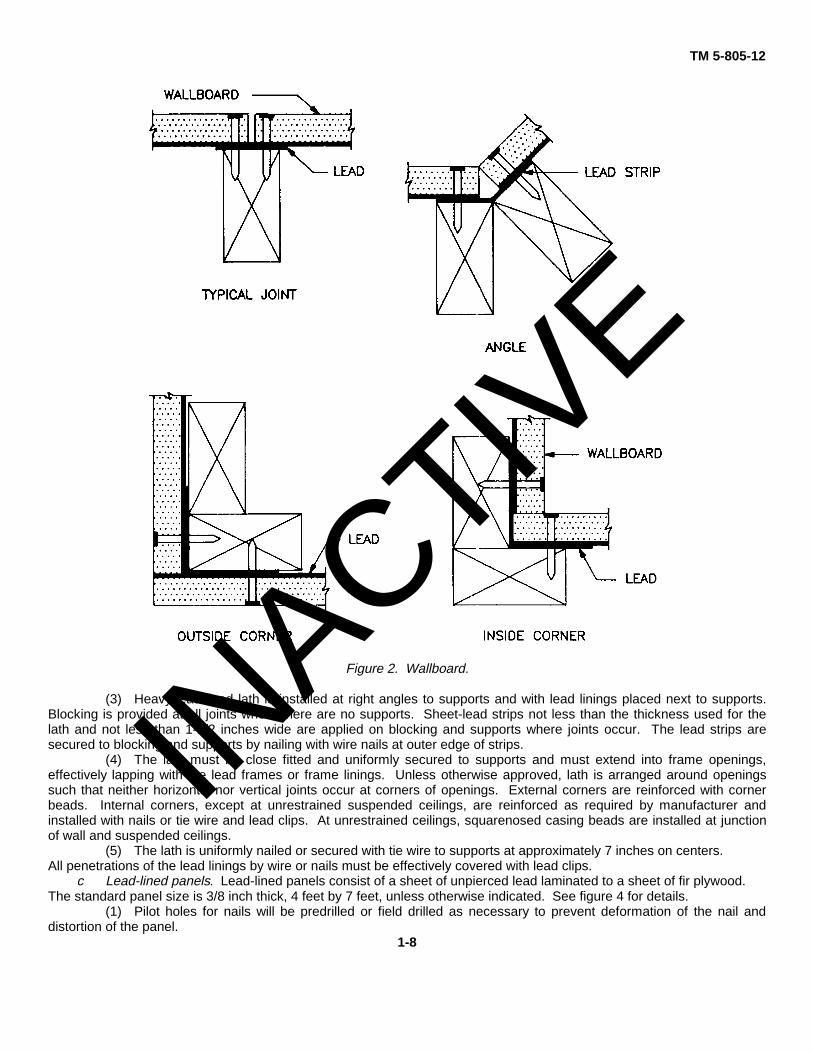
Figure 2. Wallboard.
(3) Heavy lead-lined lath is installed at right angles to supports and with lead linings placed next to supports.Blocking is provided at all joints where there are no supports. Sheet-lead strips not less than the thickness used for thelath and not less than 1-1/2 inches wide are applied on blocking and supports where joints occur. The lead strips aresecured to blocking and supports by nailing with wire nails at outer edge of strips.
(4) The lath must be close fitted and uniformly secured to supports and must extend into frame openings,effectively lapping with the lead frames or frame linings. Unless otherwise approved, lath is arranged around openingssuch that neither horizontal nor vertical joints occur at corners of openings. External corners are reinforced with cornerbeads. Internal corners, except at unrestrained suspended ceilings, are reinforced as required by manufacturer andinstalled with nails or tie wire and lead clips. At unrestrained ceilings, squarenosed casing beads are installed at junctionof wall and suspended ceilings.
(5) The lath is uniformly nailed or secured with tie wire to supports at approximately 7 inches on centers.All penetrations of the lead linings by wire or nails must be effectively covered with lead clips.
c Lead-lined panels. Lead-lined panels consist of a sheet of unpierced lead laminated to a sheet of fir plywood.The standard panel size is 3/8 inch thick, 4 feet by 7 feet, unless otherwise indicated. See figure 4 for details.
(1) Pilot holes for nails will be predrilled or field drilled as necessary to prevent deformation of the nail anddistortion of the panel.
1-8
INACTIV
E
TM 5-805-12
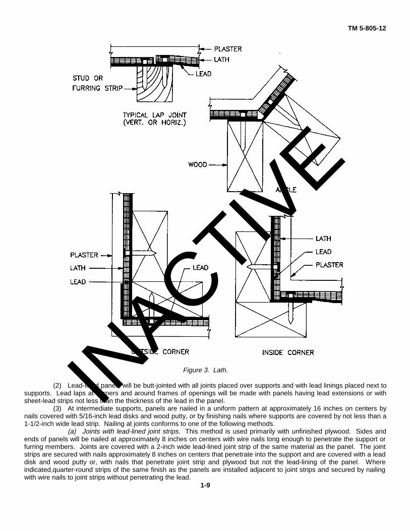
Figure 3. Lath.
(2) Lead-lined panels will be butt-jointed with all joints placed over supports and with lead linings placed next tosupports. Lead laps at corners and around frames of openings will be made with panels having lead extensions or withsheet-lead strips not less than the thickness of the lead in the panel.
(3) At intermediate supports, panels are nailed in a uniform pattern at approximately 16 inches on centers bynails covered with 5/16-inch lead disks and wood putty, or by finishing nails where supports are covered by not less than a1-1/2-inch wide lead strip. Nailing at joints conforms to one of the following methods.
(a) Joints with lead-lined joint strips. This method is used primarily with unfinished plywood. Sides andends of panels will be nailed at approximately 8 inches on centers with wire nails long enough to penetrate the support orfurring members. Joints are covered with a 2-inch wide lead-lined joint strip of the same material as the panel. The jointstrips are secured with nails approximately 8 inches on centers that penetrate into the support and are covered with a leaddisk and wood putty or, with nails that penetrate joint strip and plywood but not the lead-lining of the panel. Whereindicated,quarter-round strips of the same finish as the panels are installed adjacent to joint strips and secured by nailingwith wire nails to joint strips without penetrating the lead.
1-9
INACTIV
E
TM 5-805-12
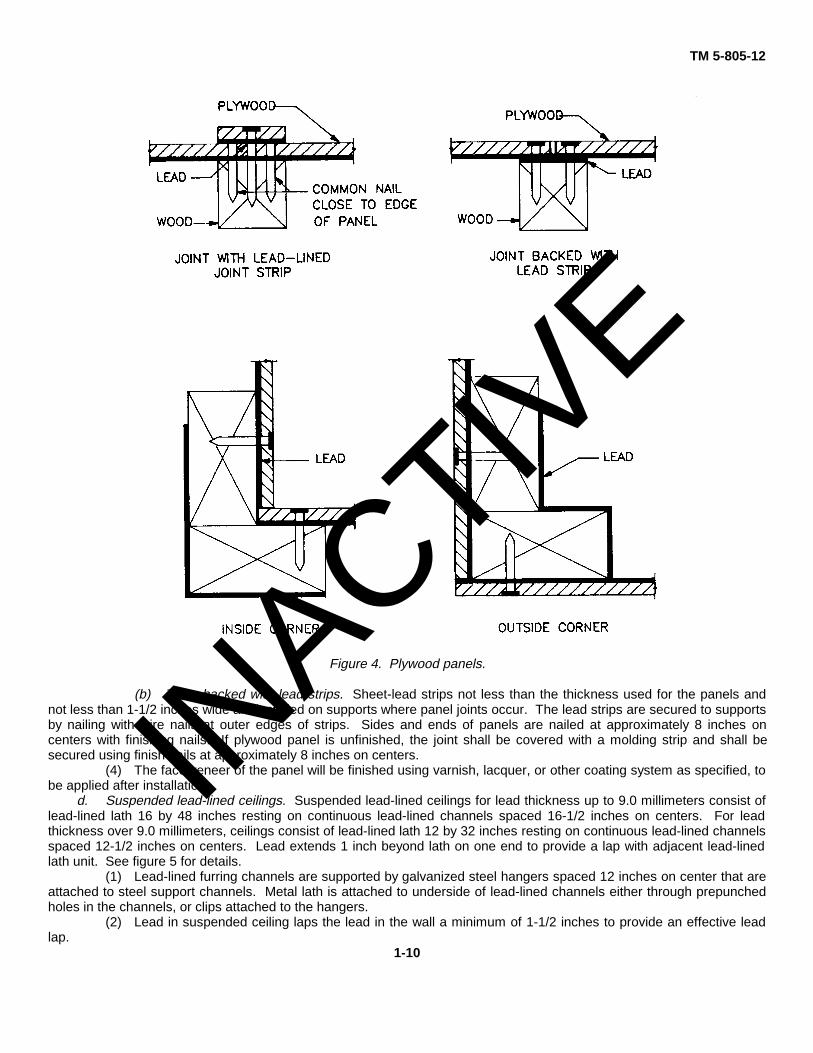
Figure 4. Plywood panels.
(b) Joints backed with lead strips. Sheet-lead strips not less than the thickness used for the panels andnot less than 1-1/2 inches wide are installed on supports where panel joints occur. The lead strips are secured to supportsby nailing with wire nails at outer edges of strips. Sides and ends of panels are nailed at approximately 8 inches oncenters with finishing nails. If plywood panel is unfinished, the joint shall be covered with a molding strip and shall besecured using finish nails at approximately 8 inches on centers.
(4) The face veneer of the panel will be finished using varnish, lacquer, or other coating system as specified, tobe applied after installation.
d. Suspended lead-lined ceilings. Suspended lead-lined ceilings for lead thickness up to 9.0 millimeters consist oflead-lined lath 16 by 48 inches resting on continuous lead-lined channels spaced 16-1/2 inches on centers. For leadthickness over 9.0 millimeters, ceilings consist of lead-lined lath 12 by 32 inches resting on continuous lead-lined channelsspaced 12-1/2 inches on centers. Lead extends 1 inch beyond lath on one end to provide a lap with adjacent lead-linedlath unit. See figure 5 for details.
(1) Lead-lined furring channels are supported by galvanized steel hangers spaced 12 inches on center that areattached to steel support channels. Metal lath is attached to underside of lead-lined channels either through prepunchedholes in the channels, or clips attached to the hangers.
(2) Lead in suspended ceiling laps the lead in the wall a minimum of 1-1/2 inches to provide an effective leadlap.
1-10
INACTIV
E

TM 5-805-12
Figure 5. Suspended lath ceiling.
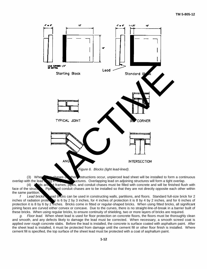
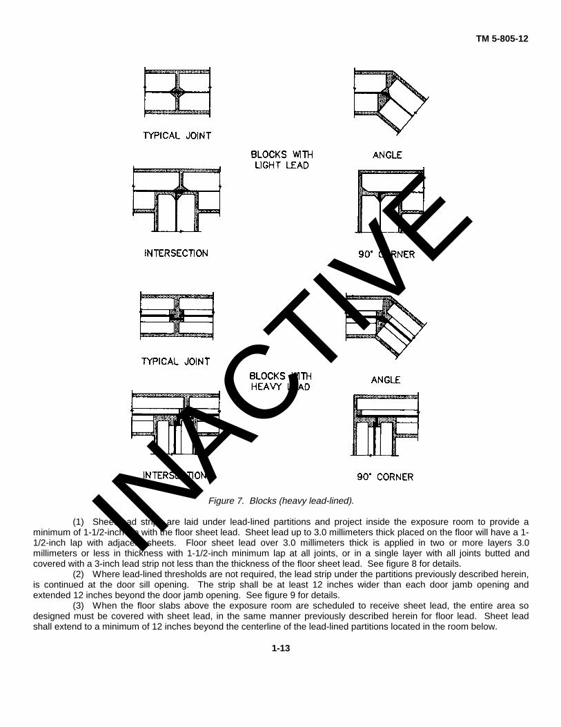
e. Lead-lined blocks. Lead-lined blocks, also called leadcore blocks, consist of an unpierced sheet of lead bondedin the center of a block of lightweight aggregate and concrete. Block sizes will be 12 by 12 by 4 inches for lead thicknessless than 6.0 millimeters, and 12 by 12 by 6 inches for lead thickness over 6.0 millimeters, with enough half-blocks forproper bonding of the wall. The blocks are an interlocking lock-joint and self-aligning type. Blocks designed to have leadlaps at joints are erected in a manner that provides a minimum 1 inch tight lap without soldering or burning. Heavy lead-lined blocks, with a lead thickness from 9.0 millimeters to 20.0 millimeters, or heavier are used for high-energy radiationshielding. The heavy lead-lined blocks are designed to receive a lead bar, of the same thickness of lead used in blocks,horizontally and vertically at all joints to provide an effective lead lap with adjoining blocks. See figures 6 and 7 for details.
(1) Where the floor is lead-lined, the first course of blocks is laid on lead strips at least 7 inches wide and willproject at least 3 inches inside the partition. Starter blocks are required when the sheet lead that is cast in the center ofthe block is over 6.0 millimeters thick. Lead-lined blocks are installed in courses with staggered vertical joints. Amaximum 1/2-inch mortar joint is allowed. Mortar between lead laps is not permitted.
(2) The lead-lined blocks with a lead thickness less than 9.0 millimeters will have rabbetted edges formed byoff-setting slabs on opposite sides of the lead. The lead is exposed on all sides to provide a 1-inch lap at all joints wheninstalled.
1-11
INACTIV
E
TM 5-805-12
Figure 6. Blocks (light lead-lined).
(3) Where pipe chases or other obstructions occur, unpierced lead sheet will be installed to form a continuousoverlap with the lead lining in adjoining structures. Overlapping lead on adjoining structures will form a tight overlap.
(4) Voids around frames, pipes, and conduit chases must be filled with concrete and will be finished flush withface of the structure. Pipes and conduit chases are to be installed so that they are not directly opposite each other withinthe same partition.
f Lead bricks . Lead bricks can be used in constructing walls, partitions, and floors. Standard full-size brick for 2inches of radiation protection is 6 by 2 by 3 inches, for 4 inches of protection it is 8 by 4 by 2 inches, and for 6 inches ofprotection it is 8 by 6 by 2 inches. Bricks come in fitted or regular-shaped bricks. When using fitted bricks, all significantjoining faces are curved either convex or concave. Due to the curves, there is no straight-line-of-break in a barrier built ofthese bricks. When using regular bricks, to ensure continuity of shielding, two or more layers of bricks are required.
g. Floor lead. When sheet lead is used for floor protection on concrete floors, the floors must be thoroughly cleanand smooth, and any defects likely to damage the lead must be corrected. When necessary, a smooth screed coat isapplied over rough concrete slabs. Before the lead is installed, the concrete is surface coated with asphaltum paint. Afterthe sheet lead is installed, it must be protected from damage until the cement fill or other floor finish is installed. Wherecement fill is specified, the top surface of the sheet lead must be protected with a coat of asphaltum paint.
1-12
INACTIV
E
TM 5-805-12
Figure 7. Blocks (heavy lead-lined).
(1) Sheet-lead strips are laid under lead-lined partitions and project inside the exposure room to provide aminimum of 1-1/2-inch lap with the floor sheet lead. Sheet lead up to 3.0 millimeters thick placed on the floor will have a 1-1/2-inch lap with adjacent sheets. Floor sheet lead over 3.0 millimeters thick is applied in two or more layers 3.0millimeters or less in thickness with 1-1/2-inch minimum lap at all joints, or in a single layer with all joints butted andcovered with a 3-inch lead strip not less than the thickness of the floor sheet lead. See figure 8 for details.
(2) Where lead-lined thresholds are not required, the lead strip under the partitions previously described herein,is continued at the door sill opening. The strip shall be at least 12 inches wider than each door jamb opening andextended 12 inches beyond the door jamb opening. See figure 9 for details.
(3) When the floor slabs above the exposure room are scheduled to receive sheet lead, the entire area sodesigned must be covered with sheet lead, in the same manner previously described herein for floor lead. Sheet leadshall extend to a minimum of 12 inches beyond the centerline of the lead-lined partitions located in the room below.
1-13
INACTIV
E

TM 5-805-12
Figure 8. Floor lead.
9. Lead-lined doors and accessories.The number of lead or lead-lined items can be extensive. The list can include control window frames, speaking grills,louvers, control screens, transfer cabinets, hanger pass boxes, door frames, locksets, and dead locks. Listed below aresome of the available lead-lined items, including leaded glass.
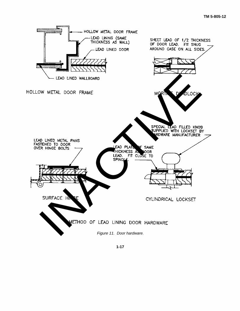
a. Lead-lined doors. Lead-lined doors are a solid wood core or hollow metal flush type door.(1) Solid wood core doors consist of two solid wood cores with a lead sheet between, of the same thickness of
lead in the partition that the door is a part of, fastened together using steel bolts 1-1/2 inches from the edges of the doorand spaced at 8 inches on centers vertically and horizontally within the door. The bolts are countersunk in the wood corewith poured lead or lead dowels placed over the heads and nuts until flush with the face of the core. The door iscrossbonded, veneer is applied, and hardwood edge strips are provided to match the face veneer. Wood doors requiringhardware are mortised on the jobsite.
(2) Hollow metal doors are fabricated of 16-gauge steel with a sheet-lead core the full size of the door,supported by 16-gauge steel brackets that prevent the lead from cold flowing or sagging. The metal exterior of the door ispainted with a shop coat of primer for on-site finishing to match other colors. Openings for hardware are factory prepared.
1-14
INACTIV
E
TM 5-805-12
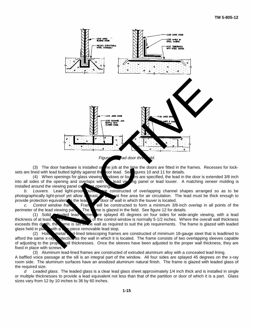
Figure 9. Lead door threshold.
(3) The door hardware is installed on the job at the time the doors are fitted in the frames. Recesses for lock-sets are lined with lead butted tightly against the door lead. See figures 10 and 11 for details.
(4) When openings for glass viewing windows or louvers are specified, the lead in the door is extended 3/8 inchinto all sides of the opening and overlaps with the lead viewing panel or lead louver. A matching veneer molding isinstalled around the viewing panel or louver openings.
b. Louvers. Lead light-proof louvers are constructed of overlapping channel shapes arranged so as to bephotographically light-proof yet allow at least 30 percent free area for air circulation. The lead must be thick enough toprovide protection equivalent to the lead in the door or wall in which the louver is located.
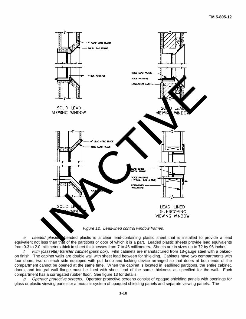
c. Control window frames. Frames will be constructed to form a minimum 3/8-inch overlap in all points of theperimeter of the lead viewing panel. The frame is glazed in the field. See figure 12 for details.
(1) Solid extruded lead frames are splayed 45 degrees on four sides for wide-angle viewing, with a leadthickness of at least 3/16 inch. The depth of the control window is normally 5-1/2 inches. Where the overall wall thicknessexceeds this depth, the frame is set in the wall as required to suit the job requirements. The frame is glazed with leadedglass held in place with a one-piece removable lead stop.
(2) Hollow metal lead-lined telescoping frames are constructed of minimum 18-gauge steel that is leadlined toafford the same x-ray protection as the wall in which it is located. The frame consists of two overlapping sleeves capableof adjusting to the proper wall thicknesses. Once the sleeves have been adjusted to the proper wall thickness, they arefixed in place with screws.
(3) Aluminum lead-lined frames are constructed of extruded aluminum alloy with a concealed lead lining.A baffled voice passage at the sill is an integral part of the window. All four sides are splayed 45 degrees on the x-rayroom side. The aluminum surfaces have an anodized aluminum natural finish. The frame is glazed with leaded glass ofthe required size.
d Leaded glass. The leaded glass is a clear lead glass sheet approximately 1/4 inch thick and is installed in singleor multiple thicknesses to provide a lead equivalent not less than that of the partition or door of which it is a part. Glasssizes vary from 12 by 10 inches to 36 by 60 inches.
1-15
INACTIV
E

TM 5-805-12
Figure 10. Lead-lined doors.
1-16
INACTIV
E
TM 5-805-12
Figure 11. Door hardware.
1-17
INACTIV
E
TM 5-805-12
Figure 12. Lead-lined control window frames.
e. Leaded plastic. Leaded plastic is a clear lead-containing plastic sheet that is installed to provide a leadequivalent not less than that of the partitions or door of which it is a part. Leaded plastic sheets provide lead equivalentsfrom 0.3 to 2.0 millimeters thick in sheet thicknesses from 7 to 46 millimeters. Sheets are in sizes up to 72 by 96 inches.
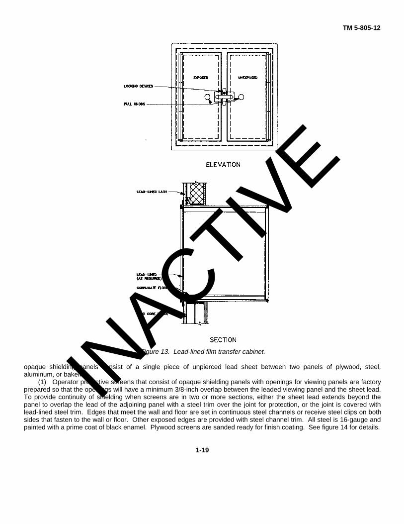
f. Film (cassette) transfer cabinet (pass box). Film cabinets are manufactured from 18-gauge steel with a baked-on finish. The cabinet walls are double wall with sheet lead between for shielding. Cabinets have two compartments withfour doors, two on each side equipped with pull knob and locking device arranged so that doors at both ends of thecompartment cannot be opened at the same time. When the cabinet is located in leadlined partitions, the entire cabinet,doors, and integral wall flange must be lined with sheet lead of the same thickness as specified for the wall. Eachcompartment has a corrugated rubber floor. See figure 13 for details.
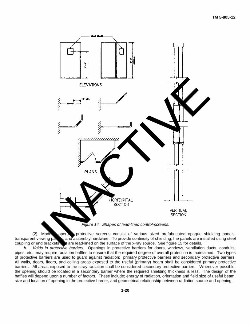
g. Operator protective screens. Operator protective screens consist of opaque shielding panels with openings forglass or plastic viewing panels or a modular system of opaqued shielding panels and separate viewing panels. The
1-18
INACTIV
E
TM 5-805-12
Figure 13. Lead-lined film transfer cabinet.
opaque shielding panels consist of a single piece of unpierced lead sheet between two panels of plywood, steel,aluminum, or bakelite.
(1) Operator protective screens that consist of opaque shielding panels with openings for viewing panels are factoryprepared so that the openings will have a minimum 3/8-inch overlap between the leaded viewing panel and the sheet lead.To provide continuity of shielding when screens are in two or more sections, either the sheet lead extends beyond thepanel to overlap the lead of the adjoining panel with a steel trim over the joint for protection, or the joint is covered withlead-lined steel trim. Edges that meet the wall and floor are set in continuous steel channels or receive steel clips on bothsides that fasten to the wall or floor. Other exposed edges are provided with steel channel trim. All steel is 16-gauge andpainted with a prime coat of black enamel. Plywood screens are sanded ready for finish coating. See figure 14 for details.
1-19
INACTIV
E
TM 5-805-12
Figure 14. Shapes of lead-lined control-screens.
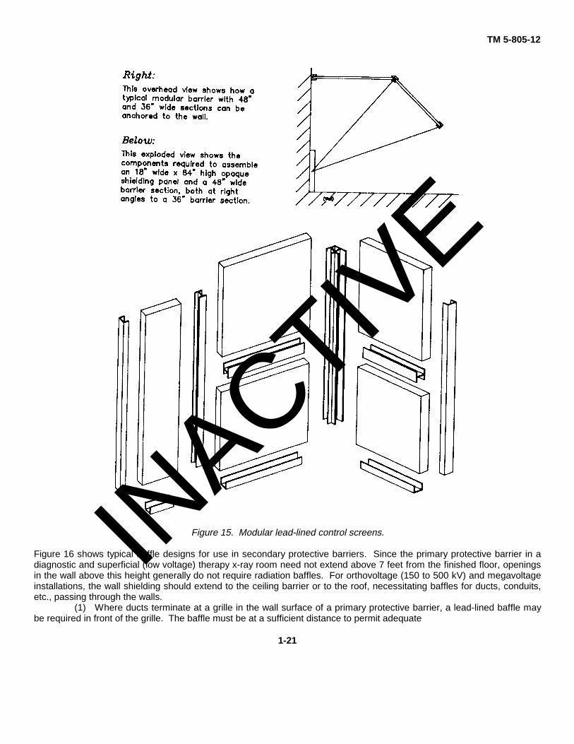
(2) Modular operator protective screens consist of various sized prefabricated opaque shielding panels,transparent viewing panels, and assembly hardware. To provide continuity of shielding, the panels are installed using steelcoupling or end brackets that are lead-lined on the surface of the x-ray source. See figure 15 for details.
h. Voids in protective barriers. Openings in protective barriers for doors, windows, ventilation ducts, conduits,pipes, etc., may require radiation baffles to ensure that the required degree of overall protection is maintained. Two typesof protective barriers are used to guard against radiation: primary protective barriers and secondary protective barriers.All walls, doors, floors, and ceiling areas exposed to the useful (primary) beam shall be considered primary protectivebarriers. All areas exposed to the stray radiation shall be considered secondary protective barriers. Whenever possible,the opening should be located in a secondary barrier where the required shielding thickness is less. The design of thebaffles will depend upon a number of factors. These include; energy of radiation, orientation and field size of useful beam,size and location of opening in the protective barrier, and geometrical relationship between radiation source and opening.
1-20
INACTIV
E
TM 5-805-12
Figure 15. Modular lead-lined control screens.
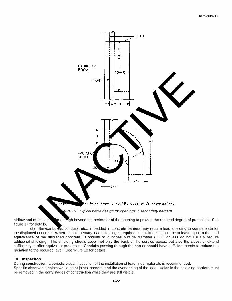
Figure 16 shows typical baffle designs for use in secondary protective barriers. Since the primary protective barrier in adiagnostic and superficial (low voltage) therapy x-ray room need not extend above 7 feet from the finished floor, openingsin the wall above this height generally do not require radiation baffles. For orthovoltage (150 to 500 kV) and megavoltageinstallations, the wall shielding should extend to the ceiling barrier or to the roof, necessitating baffles for ducts, conduits,etc., passing through the walls.
(1) Where ducts terminate at a grille in the wall surface of a primary protective barrier, a lead-lined baffle maybe required in front of the grille. The baffle must be at a sufficient distance to permit adequate
1-21
INACTIV
E
TM 5-805-12
Figure 16. Typical baffle design for openings in secondary barriers.
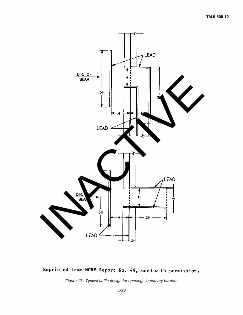
airflow and must extend far enough beyond the perimeter of the opening to provide the required degree of protection. Seefigure 17 for details.
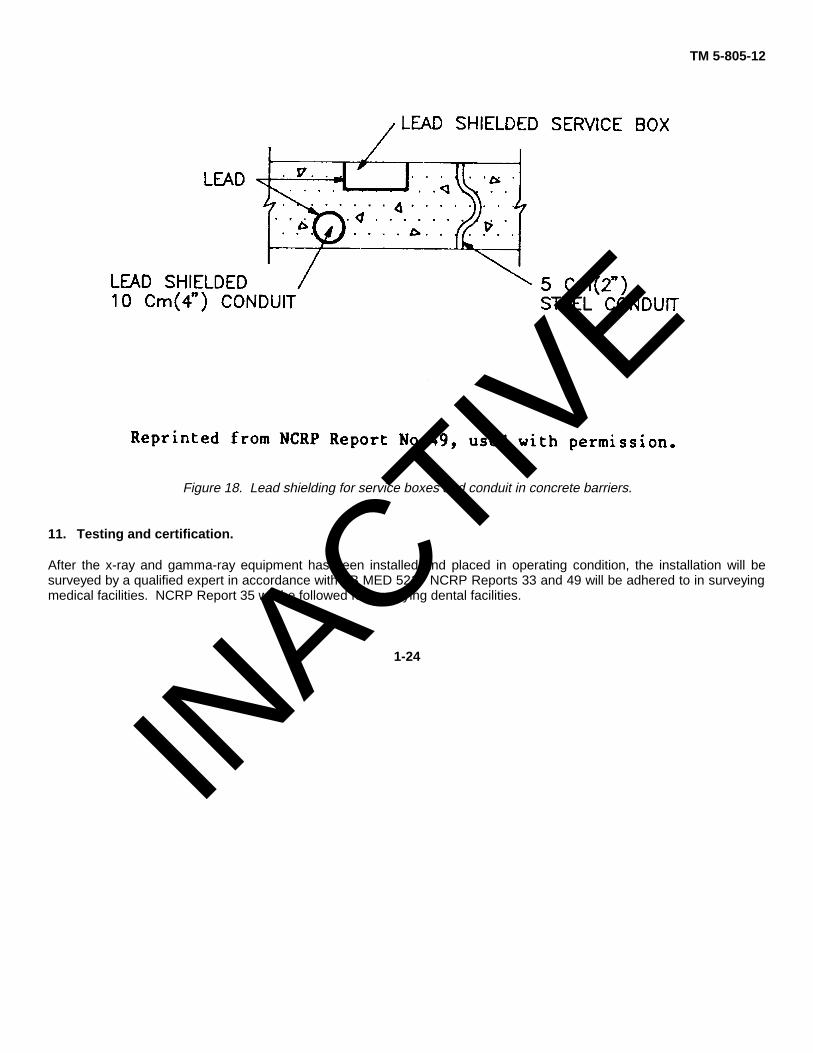
(2) Service boxes, conduits, etc., imbedded in concrete barriers may require lead shielding to compensate forthe displaced concrete. Where supplementary lead shielding is required, its thickness should be at least equal to the leadequivalence of the displaced concrete. Conduits of 2 inches outside diameter (O.D.) or less do not usually requireadditional shielding. The shielding should cover not only the back of the service boxes, but also the sides, or extendsufficiently to offer equivalent protection. Conduits passing through the barrier should have sufficient bends to reduce theradiation to the required level. See figure 18 for details.
10. Inspection.During construction, a periodic visual inspection of the installation of lead-lined materials is recommended.Specific observable points would be at joints, corners, and the overlapping of the lead. Voids in the shielding barriers mustbe removed in the early stages of construction while they are still visible.
1-22
INACTIV
E
TM 5-805-12
Figure 17. Typical baffle design for openings in primary barriers.
1-23
INACTIV
E
TM 5-805-12
Figure 18. Lead shielding for service boxes and conduit in concrete barriers.
11. Testing and certification.
After the x-ray and gamma-ray equipment has been installed and placed in operating condition, the installation will besurveyed by a qualified expert in accordance with TB MED 521. NCRP Reports 33 and 49 will be adhered to in surveyingmedical facilities. NCRP Report 35 will be followed for surveying dental facilities.
1-24
INACTIV
E

TM 5-805-12
GLOSSARYControlled area. The defined area in which theexposure of persons to radiation is supervised by aRadiation Protection Officer. Controlled areas requirecontrol of access, occupancy, and working conditions.Half-value layer (HVL). Thickness of a specifiedsubstance which, when introduced into the path of agiven beam of radiation, reduces the exposure rate byone-half.Kilovolt (kV). A unit of electrical potential differenceequal to 1000 volts.Kilovolt peak (kVp). The crest value in kilovolts of thepotential difference of a pulsating potential generator.When only one-half of the wave is used, the value refersto the useful half of the cycle.Lead equivalence. The attenuation of a materialexpressed in an equivalent thickness of lead.Million electron volts (MeV). Energy equal to thatacquired by a particle with one electronic charge beingaccelerated through a potential difference of 1 millionvolts (1MV).Noncontrolled area. Any space not meeting thedefinition of controlled area.Occupiable area. Any room or other space, indoors oroutdoors, that is likely to be occupied during irradiationby any person, either regularly or periodically during thecourse of his/her work, habitation, or recreation.Primary radiation. Radiation arising directly from thetarget of an x-ray tube or from a radioactive source.
Protective barrier. A barrier of radiation-attenuatingmaterial used to give the required protection fromradiation exposure.Qualified expert. With reference to radiation protection,a person having the knowledge and training to adviseregarding radiation protection needs, to measure ionizingradiation, and to evaluate safety techniques; a personhaving relevant certification from the American Board ofRadiology or American Board of Health Physics, orequivalent qualifications.With reference to shielding design, a person havingparticular knowledge and training in the field of medicalx-ray and gamma-ray shielding.Radiation (Ionizing). Any electromagnetic or particulateradiation capable of producing ions, directly or indirectly,by interaction with matter, specifically x-rays andgamma-rays.Radiation protection survey. An evaluation of theradiation safety in and around an installation.Radiation protection officer. The person directlyresponsible for radiation protection.Scattered radiation. Radiation that has been deviatedin direction during passage through matter.Secondary protective barrier. Barrier sufficient toattenuate stray or secondary radiation to the requireddegree.Useful beam. Radiation that passes through thewindow, aperture, cone, or other collimating device of thesource housing. Sometimes called "primary beam."
Glossary 1
INACTIV
E

TM 5-805-12
The proponent agency of this publication is Headquarters, U.S. Army Corps of Engineers. Usersare invited to send comments and suggested improvements on DA Form 2028 (RecommendedChanges to Publications and Blank Forms) to HQUSACE (CEMP-ES), WASH, DC 20314-1000.
By Order of the Secretary of the Army:
CARL E. VUONOGeneral United States Army
Chief of StaffOfficial:
WILLIAM J. MEEHAN IIBrigadier General United States Army
The Adjutant General
Distribution:Army: To be distributed in accordance with DA Form 12-34B, block 723 requirements for X-Ray Shielding.
*U.S. GOVERNMENT PRINTING OFFICE : 1993 O - 342-421 (62142)
INACTIV
E
INACTIV
E

PIN: 005316INACTIV
E