Embed Size (px)
Citation preview

UFC 3-501-01 February 3, 2010
Replaces 3-500-10 (DRAFT) and 3-500-10N (DRAFT)
UNIFIED FACILITIES CRITERIA (UFC)
ELECTRICAL ENGINEERING
APPROVED FOR PUBLIC RELEASE: DISTRIBUTION UNLIMITED

UFC 3-501-01 February 3, 2010
Replaces 3-500-10 (DRAFT) and 3-500-10N (DRAFT)
ELECTRICAL ENGINEERING
Any copyrighted material included in this UFC is identified at the point of use. Use of the copyrighted material apart from this UFC must have the permission of the copyright holder. NAVAL FACILITIES ENGINEERING COMMAND (Preparing Activity) U.S. ARMY CORPS OF ENGINEERS AIR FORCE CIVIL ENGINEER SUPPORT AGENCY Record of Changes (changes are indicated by \1\…/1/) Change No. Date: Location

UFC 3-501-01 February 3, 2010
Replaces 3-500-10 (DRAFT) and 3-500-10N (DRAFT)
FOREWORD The Unified Facilities Criteria (UFC) system is prescribed by MIL-STD 3007 and provides planning, design, construction, sustainment, restoration, and modernization criteria, and applies to the Military Departments, the Defense Agencies, and the DoD Field Activities in accordance with USD (AT&L) Memorandum dated 29 May 2002. UFC will be used for all DoD projects and work for other customers where appropriate. All construction outside of the United States is also governed by Status of forces Agreements (SOFA), Host Nation Funded Construction Agreements (HNFA), and in some instances, Bilateral Infrastructure Agreements (BIA.) Therefore, the acquisition team must ensure compliance with the more stringent of the UFC, the SOFA, the HNFA, and the BIA, as applicable. UFC are living documents and will be periodically reviewed, updated, and made available to users as part of the Services’ responsibility for providing technical criteria for military construction. Headquarters, U.S. Army Corps of Engineers (HQUSACE), Naval Facilities Engineering Command (NAVFAC), and Air Force Civil Engineer Support Agency (AFCESA) are responsible for administration of the UFC system. Defense agencies should contact the preparing service for document interpretation and improvements. Technical content of UFC is the responsibility of the cognizant DoD working group. Recommended changes with supporting rationale should be sent to the respective service proponent office by the following electronic form: Criteria Change Request (CCR). The form is also accessible from the Internet sites listed below. UFC are effective upon issuance and are distributed only in electronic media from the following source:
• Whole Building Design Guide web site http://www.wbdg.org/.
Hard copies of UFC printed from electronic media should be checked against the current electronic version prior to use to ensure that they are current.
______________________________________ JAMES C. DALTON, P.E. Chief, Engineering and Construction U.S. Army Corps of Engineers
______________________________________ JOSEPH E. GOTT, P.E. Chief Engineer Naval Facilities Engineering Command
______________________________________ DENNIS FIRMAN Director of the Air Force Center for Engineering
and the Environment Department of the Air Force
______________________________________ MICHAEL McANDREW Director, Facility Investment and Management Office of the Deputy Under Secretary of Defense (Installations and Environment)

UFC 3-501-01 February 3, 2010
Replaces 3-500-10 (DRAFT) and 3-500-10N (DRAFT)
UNIFIED FACILITIES CRITERIA (UFC) NEW DOCUMENT SUMMARY SHEET
Document: UFC 3-501-01, Electrical Engineering Superseding:
Draft UFC 3-500-10, Electrical Engineering has been renumbered to this document. Draft UFC 3-500-10 superceded Draft UFC 3-500-10N, Electrical Engineering. These documents were made mandatory guidance by the Navy and published on the Navy Design-Build Master (NDBM) website at http://www.wbdg.org/ndbm/design_guidance.php.
UFC 3-501-03N, Electrical Engineering Preliminary Considerations. Description: This UFC 3-501-01 provides electrical engineering design and analysis criteria for design-build and design-bid-build projects. It is organized to provide the top-level electrical guidance and refers to other UFCs as appropriate.
Reasons for Document:
Provides technical requirements for exterior and interior electrical system design criteria.
Establishes design analysis requirements in support of design activities.
Defines minimum requirements for design drawings in terms of drawing types and content.
Provides links to related material in other UFCs. Impact: There are negligible cost impacts associated with this UFC. However, the following benefits should be realized.
Standardized guidance has been prepared to assist electrical engineers in the development of the plans, specifications, calculations, and Design/Build Request for Proposals (RFP).
This UFC coordinates with all electrical-related UFCs and provides consistent guidance with the other electrical-related UFCs.

UFC 3-501-01 February 3, 2010
Replaces 3-500-10 (DRAFT) and 3-500-10N (DRAFT)
i
CONTENTS Page
CHAPTER 1 INTRODUCTION........................................................................................ 1
1-1 PURPOSE AND SCOPE. ................................................................................. 1 1-2 APPLICABILITY................................................................................................ 1 1-3 REFERENCES. ................................................................................................ 1 1-4 DESIGN STANDARDS. .................................................................................... 3 1-5 TECHNICAL POINTS OF CONTACT. .............................................................. 3 1-6 PERMITS – CONSTRUCTION, ENVIRONMENTAL, AND OTHER. ................ 4
CHAPTER 2 DESIGN REQUIREMENTS........................................................................ 5
2-1 GENERAL GUIDANCE..................................................................................... 5 2-1.1 Hazardous Materials and Waste................................................................ 5 2-1.2 Removal of Existing Cables and Conductors............................................. 5 2-1.3 Modification to Existing Electrical Equipment............................................. 6 2-1.4 Salvaged Materials and Equipment. .......................................................... 6 2-1.5 Scheduling and Sequencing Outages........................................................ 6 2-1.6 Calculations. .............................................................................................. 6 2-1.7 Energy Efficiency and Sustainable Design. ............................................... 6 2-1.8 Antiterrorism and Physical Security. .......................................................... 7 2-1.9 Design Considerations in Coastal and High Humidity Areas. .................... 7 2-1.10 Arc Flash Warning Labels.......................................................................... 8
2-2 SITE EXTERIOR POWER DISTRIBUTION SYSTEMS.................................... 8 2-2.1 Exterior Power Distribution Systems, Including Housing Areas. ................ 8 2-2.2 Dockside Utilities for Ship Service. ............................................................ 8 2-2.3 Exterior Lighting Systems. ......................................................................... 8 2-2.4 Airfield Lighting. ......................................................................................... 8 2-2.5 Cathodic Protection Systems..................................................................... 9
2-3 INTERIOR DISTRIBUTION SYSTEMS............................................................. 9 2-3.1 Interior Electrical Systems. ........................................................................ 9 2-3.2 Interior Lighting Systems. .......................................................................... 9 2-3.3 Emergency Power Systems....................................................................... 9 2-3.4 Sensitive Compartmented Information (SCIF) Facilities. ........................... 9 2-3.5 Hazardous Locations. ................................................................................ 9 2-3.6 Battery Areas and Battery Racks............................................................... 9
2-4 COMMUNICATIONS AND SECURITY. ............................................................ 9 2-4.1 Telecommunication Systems. .................................................................... 9 2-4.2 Television Systems. ................................................................................. 10 2-4.3 Community Antenna Television (CATV) Systems.................................... 10 2-4.4 Electronic Security Systems (ESS). ......................................................... 10 2-4.5 Mass Notification Systems....................................................................... 10
CHAPTER 3 DESIGN ANALYSIS AND DOCUMENTATION........................................ 11
3-1 GENERAL....................................................................................................... 11 3-2 DESIGN ANALYSIS........................................................................................ 11

UFC 3-501-01 February 3, 2010
Replaces 3-500-10 (DRAFT) and 3-500-10N (DRAFT)
ii
3-2.1 Basis of Design........................................................................................ 11 3-2.2 Electrical Calculations – Overview........................................................... 14 3-2.3 Load Analysis. ......................................................................................... 15 3-2.4 Short Circuit Analysis............................................................................... 16 3-2.5 Protective Device Time-Current Coordination Study. .............................. 17 3-2.6 Arc Flash Analyses. ................................................................................. 19 3-2.7 Voltage Drop............................................................................................ 20 3-2.8 Motor Starting/Flicker Analysis. ............................................................... 20 3-2.9 Lighting. ................................................................................................... 20 3-2.10 Manhole Design. ...................................................................................... 20 3-2.11 Cable Pulling Tension Calculations. ........................................................ 21 3-2.12 Calculations for Directional Boring. .......................................................... 21 3-2.13 Sag, Tension, and Guying Analysis. ........................................................ 21 3-2.14 Cathodic Protection Calculations. ............................................................ 21 3-2.15 Lightning Protection Calculations............................................................. 21 3-2.16 CATV Network Loss Calculations. ........................................................... 22 3-2.17 ESS Calculations. .................................................................................... 22
3-3 DRAWING REQUIREMENTS......................................................................... 22 3-3.1 Legends and Abbreviations. .................................................................... 23 3-3.2 Site Plans................................................................................................. 23 3-3.3 Demolition Plans. ..................................................................................... 25 3-3.4 Lighting Plans and Details. ...................................................................... 26 3-3.5 Power Plans............................................................................................. 26 3-3.6 Communications Plans. ........................................................................... 26 3-3.7 Grounding Plan........................................................................................ 27 3-3.8 Roof Plan. ................................................................................................ 27 3-3.9 Lightning Protection Plan. ........................................................................ 27 3-3.10 Hazardous Location Plan......................................................................... 27 3-3.11 Power One-Line/Riser Diagrams. ............................................................ 27 3-3.12 Telecommunications Riser Diagram. ....................................................... 29 3-3.13 Intercommunication/Paging Riser Diagram.............................................. 29 3-3.14 Fire Alarm Riser Diagram. ....................................................................... 30 3-3.15 Other Riser Diagrams. ............................................................................. 30 3-3.16 Schedules and Elevations........................................................................ 30 3-3.17 Details/Diagrams. .................................................................................... 31 3-3.18 Grounding Diagrams................................................................................ 31 3-3.19 Cathodic Protection. ................................................................................ 31 3-3.20 Manufacturer’s Equipment Drawings. ...................................................... 31
GLOSSARY .................................................................................................................. 33
APPENDIX A REFERENCES ....................................................................................... 36
APPENDIX B ELECTRICAL UFCs................................................................................ 38
APPENDIX C DESIGN DATA TABLES......................................................................... 41

UFC 3-501-01 February 3, 2010
Replaces 3-500-10 (DRAFT) and 3-500-10N (DRAFT)
iii
APPENDIX D ELECTRICAL ENGINEERING PRELIMINARY CONSIDERATIONS ..... 44
FIGURES
Figure 1-1 Electrical UFC Delineation ............................................................................ 2 Figure 2-1 Typical Arc Flash Warning Label ................................................................... 8 Figure B-1 Additional Electrical-Related UFCs.............................................................. 39 Figure B-2 Electrical UFCs – Future Plans.................................................................... 40
TABLES Table C-1 Typical Loading For Personal Computer Systems........................................ 41 Table C-2 Load Data For Preliminary Demand Calculations......................................... 41 Table C-3 Dwelling Demand KVA per A/C Size ............................................................ 42 Table C-4 Typical A/C Size for Dwelling Units .............................................................. 42 Table C-5 Demand for Electric Strip Heat ..................................................................... 42

UFC 3-501-01 February 3, 2010
Replaces 3-500-10 (DRAFT) and 3-500-10N (DRAFT)
1
CHAPTER 1 INTRODUCTION
1-1 PURPOSE AND SCOPE.
The purpose of this UFC is to provide technical guidance for general aspects of the electrical design of projects. The information provided in this guide must be used in the development of the plans, specifications, calculations, and Design/Build Request for Proposals (RFP) and must serve as the minimum electrical design requirements for design-build and design-bid-build projects. Project conditions may dictate the need for a design that exceeds these minimum requirements. This UFC provides the top-tier baseline guidance for electrical UFCs and is intended as a reference for all electrical work on projects. Figure 1-1 shows the relationship of this UFC to other related UFCs. They rely on this UFC for overall guidance regarding design analysis and documentation. There are existing individual service UFCs and other UFCs under development; these documents are identified in similar figures in Appendix B. Modernization of electrical systems solely for the purpose of meeting design criteria in UFCs is not required. Upgrades or modifications to electrical systems should consider the design criteria in this UFC, but it is not intended that an entire facility or system require modernization solely because of a minor modification. 1-2 APPLICABILITY.
Compliance with this UFC is mandatory for the design of electrical systems at all facilities, bases, and at leased facilities. Leased facilities are defined in UFC 4-010-01. Facilities located outside of the United States must also comply with the applicable host nation standards; refer to UFC 3-510-01 for additional information. Different voltages, frequencies, and grounding conventions often apply in other host nations; however, follow the design principles provided in this UFC to the extent practical. U.S. Department of Commerce International Trade Administration document, Electric Current Abroad, provides additional information and can be obtained at www.ita.doc.gov/media/publications/pdf/current2002final.pdf. 1-3 REFERENCES.
Appendix A contains the list of references used in this document.

UFC 3-501-01 February 3, 2010
Replaces 3-500-10 (DRAFT) and 3-500-10N (DRAFT)
2
Figure 1-1 Electrical UFC Delineation
UFC 3-501-01Electrical Engineering
UFC 3-520-01Interior
Electrical Systems
UFC 3-550-01Exterior Electrical Power Distribution
UFC 3-520-05Stationary Battery Areas
UFC 3-530-01Design:Interior and Exterior
Lighting and Controls
UFC 3-560-01Electrical Safety, O&M
Exterior Electrical
Interior Electrical
ElectricalSafety
UFC 3-580-01Telecom Building Cabling Systems
Planning and Design
Telecom
UFC 3-580-10NMCI Standard
Construction Practices
Refer to Appendix B for additional UFC delineation.

UFC 3-501-01 February 3, 2010
Replaces 3-500-10 (DRAFT) and 3-500-10N (DRAFT)
3
1-4 DESIGN STANDARDS.
Apply NFPA 70 and IEEE C2 to all electrical designs. The electrical Designer of Record must satisfy each of the following for each project:
a. Provide contract documents that fully indicate the scope of work.
b. Comply with all applicable UFCs, codes, regulations, laws, and service-specific requirements.
c. Provide a completed project within funding limits.
d. Provide a completed project within scope of work limits.
e. Provide a completed project of acceptable appearance within design standards.
f. Provide a completed project with coordinated systems (structural, mechanical, electrical, and other applicable disciplines).
g. Provide complete, accurate, and coordinated construction documentation for the project.
h. Provide a completed project considerate of the ecological, physical, and visual features of the site.
i. Compliance with applicable environmental requirements.
j. Provide a completed project that incorporates sustainable design principles.
k. Provide a completed project meeting the base exterior architectural plan. The Authority Having Jurisdiction (AHJ) for each service has the authority to interpret the applicability of the requirements in this UFC, and the codes and standards referenced herein.
For the Air Force, the AHJ is the Chief Electrical Engineer, Headquarters AFCESA/CEOA.
For the Army, the AHJ is the Headquarters, U.S. Army Corps of Engineers
(HQUSACE), Engineering and Construction (CECW-CE).
For the Navy, the AHJ is Chief Engineer, Naval Facilities Engineering Command (NAVFAC).
1-5 TECHNICAL POINTS OF CONTACT.
For the Air Force, contact the Air Force Civil Engineer Support Agency (AFCESA) at [email protected]. For the Army, contact the US Army Corps of Engineers (USACE) at [email protected].

UFC 3-501-01 February 3, 2010
Replaces 3-500-10 (DRAFT) and 3-500-10N (DRAFT)
4
For the Navy, contact Code CIEE, NAVFAC Atlantic Office at [email protected]. 1-6 PERMITS – CONSTRUCTION, ENVIRONMENTAL, AND OTHER.
Identify the permits and fees necessary for environmental, construction, and operation of facilities.

UFC 3-501-01 February 3, 2010
Replaces 3-500-10 (DRAFT) and 3-500-10N (DRAFT)
5
CHAPTER 2 DESIGN REQUIREMENTS
2-1 GENERAL GUIDANCE.
Design electrical systems to meet the needs of the activity and supporting facilities in accordance with this document. Do not specify unusual or non-standard equipment in designs. Electrical equipment must be manufacturer’s standard catalog products and must conform to the latest published industry and technical society standards at the date of contract award. Underwriters Laboratories (UL) or third-party certification is required for all basic equipment. Use of shop or field fabricated electrical equipment assemblies that are not manufacturer’s standard catalog products or do not conform to the industry and technical society standards are not acceptable. 2-1.1 Hazardous Materials and Waste.
Demolition or replacement of existing electrical equipment may involve hazardous materials and waste. This equipment includes, but is not necessarily limited to the following:
Pad mounted transformers – dielectric fluid containing PCBs, lead paint on the exterior
Pad mounted switches – dielectric fluid containing PCBs, lead paint on the exterior
Oil-fused cutout switches – dielectric fluid containing PCBs
Capacitors - dielectric fluid containing PCBs
Pole mounted transformers – dielectric fluid containing PCBs
Fluorescent ballasts – dielectric fluid containing PCBs
Fluorescent and HID lamps – mercury
Self-luminous exit signs – tritium
Lead cables – lead
Manholes and handholes – asbestos fireproofing
Storage batteries – lead, cadmium, lithium, and electrolytes 2-1.2 Removal of Existing Cables and Conductors.
When a project requires removal of existing cables and conductors enclosed in either duct or conduit, they must be physically removed. Associated ducts or conduits may be abandoned in place only for the following conditions:
They are planned for re-use.

UFC 3-501-01 February 3, 2010
Replaces 3-500-10 (DRAFT) and 3-500-10N (DRAFT)
6
Removal will cause substantial facility damage.
Conduits are inaccessible. On duct systems between underground structures (handholes, manholes, and vaults), install a pull wire (string or rope) for future use, and seal both ends of duct. 2-1.3 Modification to Existing Electrical Equipment.
Existing equipment to be “Modified” or “Added to” must be uniquely identified. This identification shall include the manufacturer’s name and other pertinent manufacturer’s identification (e.g., serial number, model number, style), if such information exists. 2-1.4 Salvaged Materials and Equipment.
Demolition projects may require equipment or material to be salvaged for, or by the Government. Uniquely identify all salvageable equipment or material. This identification shall include the manufacturer’s name and other pertinent manufacturer’s identification including serial number, model number, style, physical dimensions, and weight if such information exists. Indicate who is responsible for removal, storage, and transportation. 2-1.5 Scheduling and Sequencing Outages.
Designer of Record shall:
Determine and identify scheduling, sequencing, and outage requirements including anticipated outage durations as a part of contract design documents. Include a specific and detailed suggested sequence of construction and identify any temporary requirements.
Require the contractor to review all identified requirements and submit outage requests for approval by the Government prior to initiating the specific work task.
Require that all work complies with the electrical safety requirements contained in UFC 3-560-01 and EM-385-1. When differences occur, the UFC 3-560-01 takes precedence.
2-1.6 Calculations.
Complete calculations as specified in Chapter 3. 2-1.7 Energy Efficiency and Sustainable Design.
Comply with UFC 3-400-01 to meet the energy conservation mandates of ASHRAE 90.1; EPACT 2005; Executive Order 13423; and the Energy Independence and Security Act of 2007.

UFC 3-501-01 February 3, 2010
Replaces 3-500-10 (DRAFT) and 3-500-10N (DRAFT)
7
Provide sustainable design, energy efficiency, and green procurement of environmentally preferable materials to achieve the required LEED or other agency certification level in accordance with UFC 4-030-01. 2-1.8 Antiterrorism and Physical Security.
UFC 4-010-01 is a multidiscipline document which contains several standards that may impact electrical system design. Electrical designers must be familiar with UFC 4-010-01 and how it may affect the design of utilities, service entrance equipment, emergency backup systems, and bracing of electrical equipment. Incorporate the minimum standards into the design of all new construction and major renovations of inhabited DoD buildings. UFC 4-020-01 supports the planning of DoD facilities that include requirements for security and antiterrorism. Use in conjunction with UFC 4-010-01 to establish the security and antiterrorism design criteria that will be the basis for DoD facility designs. 2-1.9 Design Considerations in Coastal and High Humidity Areas.
The special design considerations listed below apply when electrical equipment is routinely subjected to salt spray or is installed in locations exposed to condensing humidity that has historically caused premature rusting and degradation of equipment enclosures.
Base, cabinets, and tanks of all transformers must be corrosion resistant and be fabricated of stainless steel.
Use stainless steel cabinets and hardware for pad-mounted switchgear and sectionalizing termination cabinets.
Use stainless steel enclosures and hardware for exterior safety switches and other electrical equipment.
Do not use aluminum-conductor steel-reinforced (ACSR) overhead conductors.
The special design considerations always apply and are required for electrical equipment physically located on piers and wharfs.
When feasible, equipment enclosures can be designed to comply with NEMA 4X non-metallic enclosure requirements instead of stainless steel if the enclosures are not subject to physical or structural integrity damage.

UFC 3-501-01 February 3, 2010
Replaces 3-500-10 (DRAFT) and 3-500-10N (DRAFT)
8
2-1.10 Arc Flash Warning Labels.
Provide arc flash warning labels on switchgear, switchboards, panelboards, disconnect switches, industrial control panels, meter socket enclosures, and motor control centers that are in other than dwelling occupancies in accordance with the format shown in Figure 2-1.
Figure 2-1 Typical Arc Flash Warning Label
WARNING!
2-2 SITE EXTERIOR POWER DISTRIBUTION SYSTEMS.
The site utility distribution system must be compatible with the existing system and comply with UFC 3-550-01. Where the site service is derived from an existing primary feeder, the designer must verify that the existing circuit can support the new loads. 2-2.1 Exterior Power Distribution Systems, Including Housing Areas.
Comply with UFC 3-550-01. 2-2.2 Dockside Utilities for Ship Service.
Comply with UFC 4-150-02. 2-2.3 Exterior Lighting Systems.
Comply with UFC 3-530-01. 2-2.4 Airfield Lighting.
Comply with UFC 3-535-01.

UFC 3-501-01 February 3, 2010
Replaces 3-500-10 (DRAFT) and 3-500-10N (DRAFT)
9
2-2.5 Cathodic Protection Systems.
Comply with UFC 3-570-02N for the Navy and UFC 3-570-02A for the Army. 2-3 INTERIOR DISTRIBUTION SYSTEMS.
2-3.1 Interior Electrical Systems.
Comply with UFC 3-520-01. 2-3.2 Interior Lighting Systems.
Comply with UFC 3-530-01. 2-3.3 Emergency Power Systems.
2-3.3.1 Exit and Emergency Lighting. Comply with UFC 3-530-01. 2-3.3.2 Fire Alarm Systems. Comply with UFC 3-600-01. 2-3.3.3 Emergency Generators. Comply with UFC 3-520-01. 2-3.4 Sensitive Compartmented Information (SCIF) Facilities.
Comply with DCID 6/9. 2-3.5 Hazardous Locations.
Show boundaries of hazardous locations on the plans and identify the type of hazard by class, division, and group. 2-3.6 Battery Areas and Battery Racks.
Comply with UFC 3-520-05. 2-4 COMMUNICATIONS AND SECURITY.
2-4.1 Telecommunication Systems.
2-4.1.1 General. Overhead and underground communications systems must comply with UFC 3-580-01 and, additionally for the Navy, UFC 3-580-10. However, the requirements of this paragraph take precedence if conflicts with UFC 3-580-01 and 3-580-10 exist. Coordinate requirements with the Base Communications Officer (BCO). For the Navy, coordinate NMCI data service with the Base NMCI Representative. 2-4.1.2 Outside Plant. Install underground telecommunications wiring in conduit to a depth of 24 in (610 mm). Specify concrete encased conduits for telecommunications systems when associated power conduits are also concrete encased.

UFC 3-501-01 February 3, 2010
Replaces 3-500-10 (DRAFT) and 3-500-10N (DRAFT)
10
Unless directed otherwise by the BCO, size outside category 3 copper cable for a minimum of one pair per 100 ft2 (9 m2) of building and provide a minimum of one 12 strand single-mode fiber optic cable for each facility. Coordinate cable selection and point of connection with the BCO and specify using RUS specifications. Provide solid-state type primary communication circuit protectors with sneak current protection for all twisted pair media terminating inside a building from an overhead or underground outside plant. 2-4.1.3 BEQ/BOQ Housing. Completely wire the building interior conforming to UFC 4-721-10 and applicable EIA/TIA standards. In BEQ/BOQ housing, the communication room may be located every three floors provided cabling distances are within EIA/TIA standards. For the Air Force, refer to ETL 02-12. 2-4.1.4 Family Housing. Provide a complete structured telecommunications system in accordance with TIA/EIA-570A. Provide Grade 1 wiring for units with less than 1500 ft2 (140 m2) and Grade 2 wiring (excluding optical fiber) for units with 1500 ft2 (140 m2) or more. Locate the distribution device adjacent to the residential load center. In addition to outlet locations required by TIA-570B, provide two outlets on opposite walls in the living room, family/great room, den/study, and each bedroom. Provide one outlet in dining room and garage. 2-4.2 Television Systems.
Coordinate television system requirements with the activity. 2-4.3 Community Antenna Television (CATV) Systems.
Refer to UFC 3-580-01. Coordinate exterior cable installation with the local service provider and Base Communications Officer (BCO). Provide a conduit and pull wire from a point of connection to the base system and the main distribution equipment. 2-4.4 Electronic Security Systems (ESS).
Design requirements for interior and exterior ESS shall be coordinated with the requiring service. Guidance for Navy and Air Force design of ESS is provided in UFC 4-021-02NF and UFC 4-020-04A for the Army.
2-4.5 Mass Notification Systems.
Comply with UFC 4-021-01.

UFC 3-501-01 February 3, 2010
Replaces 3-500-10 (DRAFT) and 3-500-10N (DRAFT)
11
CHAPTER 3 DESIGN ANALYSIS AND DOCUMENTATION
3-1 GENERAL.
This chapter defines the minimum information that must be provided at the various design submittal levels. During the design submittal process, the Designer of Record must clarify major comments with the appropriate Government reviewer rather than wait until the next submittal to respond. Whenever possible, the Designer of Record is encouraged to meet with the reviewer to discuss comments. 3-2 DESIGN ANALYSIS.
The Design Analysis is a presentation of facts to demonstrate the concept of the project is fully understood and the design is based on sound engineering principles. As a minimum, include the following information in the Design Analysis. 3-2.1 Basis of Design.
Document design decisions throughout the design process. List any special features and alternatives that were considered. Provide a written narrative accurately addressing the electrical and telecommunication design. Describe the design approach to all electrical systems. Include the method used for sizing conductors, conduit, protective devices, and other equipment. Show all calculations used in determining capacities of electrical systems. When tables from industry standards are used in the design, indicate the title, source, and date of the document. Include a complete list of all design standards and references used for the design. Update the Basis of Design for each submittal to accurately show the current state of the design. Include the information in the following sub-paragraphs as a minimum. 3-2.1.1 Exterior Distribution Systems. Describe the primary source of power including location, adequacy and characteristics. Estimate load, transformer size, and service size.
Existing Primary Power Source – Identify the location of the point of connection into the existing primary system. Address the characteristics of this primary system, including voltage, phase, number of conductors, and available fault current. Address the adequacy of the primary system; if inadequate, state measures proposed to correct the inadequacy. Evaluate the local commercial system reliability. If the data is available, review a 5-year history of service outages, including the date, time, location, duration, and cause of each outage. The commercial system reliability will influence facility electrical design decisions.
Estimated Electrical Project Load – Provide an estimate of total connected
load (kVA) and the resulting demand load (kVA).

UFC 3-501-01 February 3, 2010
Replaces 3-500-10 (DRAFT) and 3-500-10N (DRAFT)
12
Voltage Selection – Provide basis for selection of primary and secondary voltages.
Conductors – Include conductor size, type, number of conductors, insulation
voltage rating, insulation level, and type on the drawings.
Standards of Design – Describe pertinent standards of design, such as voltage drop, equipment ratings, types of luminaires, and luminance values.
Special Systems – Identify any special systems, such as Electronic Security
Systems (ESS) or Cable Television (CATV). Describe how and where the facility will connect to the basewide Mass Notification System.
Telecommunications System – Identify point of connection into base system.
Describe modifications, if required, to existing base system.
Materials – Provide manufacturer’s data sheets and product data for selected equipment.
3-2.1.2 Interior Distribution Systems. Concisely describe the electrical systems including the following: lighting systems; power systems; emergency lighting; emergency power; grounding system or systems; telecommunications system; other systems such as television and paging; physical and electronic security features such as ESS, lighting access control, or TEMPEST. Refer to NSTISSI 7000, TEMPEST Countermeasures for Facilities, for TEMPEST criteria.
a. Electrical Characteristics – Describe the electrical system to be provided and justify its selection. Indicate voltage, phase, and number of conductors.
b. Switchgear and Switchboards – Provide specific design information for the following:
Nominal system voltage.
Short circuit ratings.
Maximum voltage ratings.
Basic impulse level (BIL).
Main bus ampacity.
Single-line, plan, and elevation drawings with full details of instrumentation and relaying.
c. Estimated Electrical Loads – Provide a breakdown, by category, of the estimated loads (kVA). Include lighting, convenience outlet, mechanical

UFC 3-501-01 February 3, 2010
Replaces 3-500-10 (DRAFT) and 3-500-10N (DRAFT)
13
equipment, special operating equipment, user equipment, and miscellaneous load categories.
d. Wiring Methods – Indicate the type of wiring method, such as rigid conduit,
electrical metallic tubing, cable tray, nonmetallic sheathed cable, and where proposed to use.
e. Conductors – Indicate the type of conductors and insulation material such as
CU, AL, THW, XHHW, and where proposed to use. f. Standards of Design – Describe the proposed standards of design, such as
voltage drop, illuminance values, type of light sources, and, if applicable, a statement regarding the use of selective switching or other energy conserving features.
g. Special Systems – Describe the proposed type of systems. Indicate each
system’s function and the interrelationships between systems, when applicable. Identify government-furnished equipment, if any. Special systems include such systems as CATV, Closed Circuit Television (CCTV), Intercom, Sound, Nurse Call, Security, or Uninterruptible Power Supplies (UPS). Identify special security requirements. Identify special physical security requirements.
h. Telecommunications Systems – Describe system/systems to be used.
Identify space required for telecommunication equipment, and size of incoming duct/conduit. Include statement relative to interface provision for multi-use systems (i.e., intercom, voice, data). Include documentation concerning telecommunications room sizes.
i. Materials – Provide manufacturer’s data sheets and product data for
equipment chosen or designed around. 3-2.1.3 System Maintainability. Design the system in a way that enables periodic maintenance of the equipment. Describe periodic maintenance requirements for the equipment to be installed and explain how the proposed system design facilitates the performance of periodic maintenance. 3-2.1.4 Instrumentation and Controls. Coordinate all interfaces with instrumentation and control systems provided by other disciplines, and provide required connections, either empty conduits or power wiring as required. Normally, the designer for the discipline that is responsible for the process (such as electrical, mechanical, or civil) is also responsible for the instrumentation and controls design of that system.

UFC 3-501-01 February 3, 2010
Replaces 3-500-10 (DRAFT) and 3-500-10N (DRAFT)
14
3-2.2 Electrical Calculations – Overview.
The Designer of Record must provide calculations (in accordance with the associated follow-on paragraphs) to verify proper design and operation of the facility to the point of connection to the existing electrical systems. Calculations must be described fully, written clearly, and lead the reviewer through the design by stating all assumptions and design inputs. Computer printouts are acceptable only if accompanied by explanations to allow adequate independent review of calculation methods and results. Most electrical-related calculations for significant projects will be completed with software tools; hand calculations are typically only acceptable for minor modifications to an existing system. For power systems analyses, coordinate with the base to determine if specific software tools are required for the analyses. Whenever software tools are used to perform analyses, provide the electronic software files with each submittal. Before using any software tools, identify any base- or service-specific limitations regarding which software packages can be used. For example, the Navy authorizes the SKM software modules and EasyPower for electrical analysis. Calculations must provide complete analysis with supporting data. Analysis must cover system arrangement; voltage selection; and major equipment selections including load analysis and equipment sizing calculations. Whenever sizing electrical equipment, such as transformers, breakers, or electric cables, provide calculations to demonstrate proper facility design. The following calculations shall be provided unless the Basis of Design clearly explains why a particular calculation type is not applicable:
a. Load analysis.
b. Short circuit analysis, including protective device interrupting rating.
c. Protective device time-current coordination study.
d. Arc flash analysis.
e. Voltage drop.
f. Motor starting/flicker analysis.
g. Lighting.
h. Manhole design.
i. Cable pulling tension.
j. Directional Boring
k. Sag, tension, and guying analysis.
l. Cathodic protection calculation.
m. Lightning protection analysis.
n. CATV network loss calculations.

UFC 3-501-01 February 3, 2010
Replaces 3-500-10 (DRAFT) and 3-500-10N (DRAFT)
15
o. ESS calculations. 3-2.3 Load Analysis.
3-2.3.1 Preliminary Basis of Design. Load Analysis for Service Entrance Equipment, Including Feeders:
Complete a preliminary load analysis (Basis of Design). Base calculations on NFPA criteria and use information provided in Appendix C, as applicable.
Load Analysis for Service Entrance Transformer:
Apply the demand and diversity factors from Appendix D to the preliminary load analysis to determine the transformer size.
For building designs, the service transformer shall not exceed 12 VA/square foot
(130 VA/square meter) of facility gross floor area or 70% of the total connected load on installations served by transformer rated 300 kVA or greater. Any design calculations exceeding these requirements must be specifically approved by the technical reviewing authority.
Note: The above check is intended to serve as a simple confirmation that the facility transformer is not oversized.
3-2.3.2 Follow-On Submittals. Load Analysis for Service Entrance Equipment, Including Feeders:
Complete a load analysis (Basis of Design). Base calculations on NFPA criteria. Load Analysis for Service Entrance Transformer:
Apply the demand and diversity factors from Appendix D to the final load analysis to determine the transformer size.
For building designs, the service transformer shall not exceed 12 VA/square foot
(130 VA/square meter) of facility gross floor area or 70% of the total connected load on installations served by transformer rated 300 kVA or greater. Any design calculations exceeding these requirements must be specifically approved by the technical reviewing authority.
3-2.3.3 Load Analysis Criteria. Use the following additional criteria for the load analysis:

UFC 3-501-01 February 3, 2010
Replaces 3-500-10 (DRAFT) and 3-500-10N (DRAFT)
16
Assign no demand factor for all demand calculations for fire pump loads.
Use 100% rated main overcurrent protective devices for service sizes 400 amperes and larger.
Size the service conductors (continuous current rating) in accordance with Annex
B (Neher-McGrath method) of NFPA 70. Minimum design ampacity rating shall be larger than the ampacity rating of the main overcurrent protective device.
Design the incoming service by including spare conduit capacity to fully unload
the maximum rating of the service equipment (i.e. 1200 amperes for 1200 ampere rated equipment protected with 1000 ampere device).
Design main service equipment to provide a minimum of approximately 15%
combination of spare devices/space to accommodate future work.
Select appropriate size transformers based on the standard available three phase ratings (45, 75, 112.5, 150, 300, 500, 750, 1000, 1500, 2000, and 2500 kVA) and the calculated demand load of the facility.
For small systems or for small modifications to large systems, the load analysis can be performed manually using the above criteria. For larger systems, a power flow analysis using computer software tools is necessary to evaluate properly all of the possible facility modes of operation. 3-2.4 Short Circuit Analysis.
Complete a short circuit analysis in accordance with IEEE Std 551 and include the following in the analysis:
a. Include the utility system data as well as data for the distribution system. Contact the Contracting Officer for the utility system data and available fault current on the primary side of medium voltage equipment. When accurate data does not exist, the Designer of Record must assume that maximum available fault exists, up to a possible infinite bus on the primary side of the upstream transformer, and design the system assuming such conditions.
b. Calculate the available short circuit and ground fault currents at each bus. Incorporate any motor contribution in determining the momentary and interrupting ratings of the protective devices.
c. The study must be calculated by means of a commercially-available software program designed for the type of required analysis. Incorporate pertinent data and the rationale employed in developing the calculations in the introductory remarks of the study. Equipment interrupting capability evaluations must meet the requirements of IEEE C37.06, IEEE C37.13.1, or UL 489 criteria, as applicable.

UFC 3-501-01 February 3, 2010
Replaces 3-500-10 (DRAFT) and 3-500-10N (DRAFT)
17
d. Where diagrams will not fit on standard letter size paper, present the data determined by the short circuit study in a tabular format. Include the following:
Device identification
Operating voltage
Protective device
Device rating
Calculated short circuit current 3-2.5 Protective Device Time-Current Coordination Study.
Design the electrical system such that any fault in the system will be preferentially isolated by the selective operation of only the overcurrent protective device closest to the faulted condition. Perform a coordination study at the design stage to establish the basis for the system design and to enable completion of an initial arc flash analysis. Provide a final coordination study based on the as-built configuration of the system. Identify locations where selective coordination is not achievable, such as with instantaneous trips on molded case circuit breakers. The Designer of Record is responsible for the selective coordination of overcurrent protective devices, including protective relays and medium voltage protective devices, high side transformer protection for distribution transformers, main secondary breakers, and secondary feeder protective devices. The Designer of Record must ensure compatibility between the new equipment design and the existing distribution system. The Designer of Record must ensure that construction contract documents require the Contractor to submit manufacturer’s published time-current curves for primary fuses, relays, main secondary breakers, and secondary feeder protective devices. This information is required during the submittal process. Using the time-current curve data, the Designer of Record shall perform a coordination study in accordance with the following paragraphs to ensure that protective devices are properly coordinated. 3-2.5.1 Coordination Study. The completed study must include a system one-line diagram, short circuit and ground fault analysis, and protective coordination plots. The Designer of Record must provide to the Contractor settings for relays, main secondary breakers, secondary feeder protective devices, and any other protective devices in the circuit. The final coordination study and the specified setting information must be based on the as-built configuration. 3-2.5.2 One-Line Diagram(s). Show on the one-line diagram all electrical equipment and wiring to be protected by the overcurrent devices including breakers and fuses. Multiple one-line diagrams may be used if required to clearly present all of the required data. Also, show on the one-line diagram the following specific information:

UFC 3-501-01 February 3, 2010
Replaces 3-500-10 (DRAFT) and 3-500-10N (DRAFT)
18
a. Calculated short circuit values and X/R ratios at the project utility point of
connection.
b. Breaker and fuse ratings.
c. Transformer kVA and voltage ratings, percent impedance, and wiring connections.
d. Identification and voltage at each bus.
e. Conduit material; and feeder conductor sizes, type, insulation, length and configuration.
3-2.5.3 Coordination Curves. Prepare the coordination curves to determine the required settings of protective devices to assure selective coordination. Graphically illustrate on a log-log scale that adequate time separation exists between series devices, including the utility company upstream devices where applicable. Plot the specific time-current characteristics of each protective device in such a manner that all applicable upstream devices will be clearly shown on one sheet. Include the following information on the coordination curves:
a. Device identification.
b. Voltage and current ratios for curves.
c. 3-phase and 1-phase ANSI damage points for transformers directly fed from the switchgear.
d. Minimum melt and total clearing curves for fuses.
e. Cable damage curves.
f. Transformer inrush points.
g. Maximum short circuit current. 3-2.5.4 Settings. Develop a table to summarize the settings selected for each protective device. The table shall address all relays and relay functions. Include in the table the following:
a. Device identification and breaker or load controlled.
b. Relay CT ratios and electronic set point equivalents for relay tap, time dial, and instantaneous pickup points.
c. Circuit breaker sensor rating.
d. Fuse rating and type.
e. Ground fault pickup and time delay.
f. Differential relay settings.

UFC 3-501-01 February 3, 2010
Replaces 3-500-10 (DRAFT) and 3-500-10N (DRAFT)
19
3-2.5.5 Coordination Study Report. Include the following in each coordination study report:
a. A narrative describing the analyses performed, the methods used, and the desired method of coordinated protection of the power system.
b. Descriptive and technical data for existing devices and new protective devices. Include the manufacturers’ published data, nameplate data, and definition of the fixed or adjustable features of the existing or new protective devices.
c. Documentation of the utility company data including system voltages, fault MVA, system X/R ratio, time-current characteristic curves, current transformer ratios, and protective device settings.
d. Fully coordinated composite time-current characteristic curves to ensure coordinated power system protection between protective devices or equipment. Include recommended ratings and settings of all protective devices in tabulated form.
e. Evaluation of the total feeder inrush current with respect to relay or circuit breaker overcurrent trip settings. Power restoration following an outage should not cause a feeder trip on overcurrent.
3-2.6 Arc Flash Analyses.
Complete an arc flash evaluation in accordance with NFPA 70E and IEEE Std 1584 as part of the short circuit study to determine personal protective clothing (PPE) requirements. Note: PPE criteria shall be in accordance with Chapter 4 of UFC 3-560-01. Include the following:
Description of the software used to perform the evaluation, including an explanation of software-specific user adjustable analysis settings that were used for the study.
Scope of analysis. When switchgear, switchboards, and panelboards are equipped with main circuit breakers, provide both “Line Side” and “Bus Side” results for each item. If the facility or system has different operational configurations, such as different transformer supplies, emergency generator operation, or UPS bypass, evaluate each possible operating configuration and provide the arc flash results for each case. Summarize all data and include the worst-case results in terms of arc flash levels.
Assumed working distance in feet. For low voltage systems, assume a working distance of 18 in. For medium voltage systems, assume a minimum working distance of 4 ft. For high voltage systems, assume a minimum working distance of 6 ft.

UFC 3-501-01 February 3, 2010
Replaces 3-500-10 (DRAFT) and 3-500-10N (DRAFT)
20
Calculated energy in cal/cm2 at each evaluated location. The design goal shall be to establish arc flash levels that result in PPE levels of Category 2 or less. Consider remote racking device designs (robots) to rack breakers in and out to limit personnel exposure to an arc flash event. Specifically identify locations where Category 2 cannot be achieved, such as upstream of a main breaker (between the breaker and an upstream transformer) or downstream of UPS systems.
Specified protective device settings to achieve the arc flash results. Reconcile arc flash protective device setting recommendations with the protective device time-current coordination study.
List of prohibited energized work locations based on arc flash results. 3-2.7 Voltage Drop.
Size service and feeder conductors for a maximum voltage drop of 2 percent at the circuit’s rated capacity. Size branch circuits for a maximum voltage drop of 3 percent at the circuit’s rated capacity. If the conductor size must be increased due to voltage drop, do not increase the size of the overcurrent protection device for the circuit. The overcurrent protection device may be protecting downstream equipment and increasing the size of the overcurrent setting can reduce the level of equipment protection. If the phase conductor size is increased for voltage drop, increase the size of the equipment grounding conductor proportional to the circular mil increase of the phase conductor. 3-2.8 Motor Starting/Flicker Analysis.
Motor calculations must account for both starting and running current. Provide a motor starting/flicker analysis for motors 40 hp and greater, and for distribution in housing areas utilizing electrical HVAC systems. Verify that the voltage drop at the service entrance does not exceed 5 percent during motor starting. Refer to IEEE Std 241 for information regarding the calculation and effect of flicker. 3-2.9 Lighting.
Provide calculations for interior and exterior lighting systems in accordance with UFC 3-530-01. 3-2.10 Manhole Design.
Provide calculations verifying design requirements of UFC 3-550-01 are met.

UFC 3-501-01 February 3, 2010
Replaces 3-500-10 (DRAFT) and 3-500-10N (DRAFT)
21
3-2.11 Cable Pulling Tension Calculations.
Provide cable pulling tension calculations for all medium voltage cable. 3-2.12 Calculations for Directional Boring.
Provide calculations in accordance with UFC 3-550-01, Appendix B. 3-2.13 Sag, Tension, and Guying Analysis.
Provide for overhead distribution systems. Design power line conductors and wires in accordance with sag and tension charts and the following:
a. Limit the initial loaded conductor tension to a maximum of 50 percent of the conductor rated breaking strength. Lesser tension limits are permissible and may be preferable. Limit the maximum design tension for any conductor to 4,750 lb (21.1 kN).
b. Provide clearance requirements using final sag values in conformance with ANSI/IEEE C2 for the maximum conductor temperature. Base clearance values on the following maximum conductor temperatures:
Copper phase conductors – 75 degrees C (167 degrees F)
Aluminum/Aluminum alloy phase conductors – 90 degrees C (194 degrees F)
Neutral conductors for all multi-phase circuits – 50 degrees C (122 degrees F)
The maximum conductor temperature for single-phase neutral conductors must be identical to the phase conductors
3-2.14 Cathodic Protection Calculations.
Provide calculations for all designs. Include environmental resistivities and justify all assumptions. 3-2.15 Lightning Protection Calculations.
Provide a lightning risk assessment in accordance with NFPA 780 Annex L and document the required level of protection. If lightning protection is a design requirement, provide a lightning protection system in accordance with NFPA 780, UL 96A, and MIL-HDBK-1004/6 criteria; and provide a UL Lightning Protection Inspection Certificate for the facility. For the Air Force, apply AFI 32-1065.

UFC 3-501-01 February 3, 2010
Replaces 3-500-10 (DRAFT) and 3-500-10N (DRAFT)
22
3-2.16 CATV Network Loss Calculations.
Provide in accordance with BICSI. 3-2.17 ESS Calculations.
Provide calculations in accordance with UFC 4-021-02NF. 3-3 DRAWING REQUIREMENTS.
Provide adequate plans, including demolition, existing conditions, and new work, legends, details, and diagrams to clearly define the work to be accomplished. Coordinate construction drawings and specifications; show information only once to avoid conflicts. For the Navy, comply with UFC 1-300-09N. Utilize electrical design “Best Practices Information” located at http://www.wbdg.org/ccb/browse_cat.php?o=29&c=248 to facilitate drawing requirements and related equipment detail required by the remaining paragraphs of this UFC. Provide a General Note at the beginning of the Electrical Drawings clarifying the work to be accomplished. The following note is recommended for most jobs: “ALL ELECTRICAL WORK AND MATERIAL IS NEW AND SHALL BE PROVIDED BY THE CONTRACTOR UNLESS INDICATED OTHERWISE”.
a. Arrangement. Arrange the Electrical Drawings in accordance with the National CAD standards at http://www.buildingsmartalliance.org/ncs/.
Drawings must be clear and consistent in presentation and format.
Follow the NFPA 70 Metric Designations (mm) and Trade Sizes (in) for conduit.
b. Multiple Conduit/Cable Runs
To avoid misinterpretation as to the quantity of cables and conduit required in multiple conduit and cable runs, use one of the following acceptable descriptions:
Acceptable: Two 4-inch conduits, each containing four 500 kcmil and one
#2 Gnd
Acceptable: Two 4-inch conduits, each with four 500 kcmil and one #2 Gnd

UFC 3-501-01 February 3, 2010
Replaces 3-500-10 (DRAFT) and 3-500-10N (DRAFT)
23
Acceptable: Two 4-inch conduits, with four 500 kcmil and one #2 Gnd in each conduit
Unacceptable: Two sets of four 500 kcmil and one #2 Gnd in 4-inch conduit
Unacceptable: Parallel Service: Four 500 kcmil and one #2 Gnd in 4-inch conduit
3-3.1 Legends and Abbreviations.
All symbols used in the drawings must be defined in the legend. Locate legend on the first electrical sheet using multiple legends where required and identifying the specific use of each legend. Use different legends for new and existing work. Avoid using composite legends that include all symbols but fail to indicate which symbols are to be used on which drawings. Refer to electrical technical paper “Appendices” located at http://www.wbdg.org/ccb/browse_cat.php?o=29&c=248 for typical illustrations of how to properly display legends on the contract drawings. 3-3.2 Site Plans.
Show utility point of connectivity to the base power and telecommunications systems on the site plan. Provide explicit direction on method of entering existing manholes. Provide all details including composition of duct banks and depth and configurations of the duct banks. Electrical Site Plans must be separate and distinct from other utility site plans and must be included with the electrical drawings. Electrical and civil site plans may be combined only when the project requires minor utility work. Coordinate with the electrical engineering reviewer before combining the electrical and civil site plans. The orientation of electrical drawings must be consistent with the civil drawings. In addition, the orientation of partial building or site plans must be identical to the orientation of the larger plan from which the partial was taken. Indicate the exact title of each particular detail, partial plan or elevation as identified on the cross-referenced sheet. For overhead distribution use a separate symbol for each individual circuit; define each circuit by voltage level as well as number, size and type of conductors. Coordinate guying and conductor sag information shown on the drawings with that shown in the specifications. 3-3.2.1 Pole Details. Indicate overhead distribution pole details on the drawings.

UFC 3-501-01 February 3, 2010
Replaces 3-500-10 (DRAFT) and 3-500-10N (DRAFT)
24
NAVFAC pole details are available in Adobe PDF format and in AutoCAD format at http://www.wbdg.org/ccb/NAVGRAPH/graphtoc.pdf. Provide details in situations where an applicable pole detail has not been developed. Designer developed details must contain the same level of detail equivalent to the NAVFAC pole details and include material requirements. Review the information contained on Details OH-1.1 through OH-1.5a for examples of how to show overhead distribution work. Do not describe proposed work by referencing sketch numbers instead of pole detail designation symbols. Do not use pole detail designation symbols to describe existing facilities to be removed. To maintain the integrity of the pole details, do not modify pole details; include any required exceptions or modifications as supplemental information with the pole detail designation symbols. When using pole details, place a note referencing the pole detail designation symbols (similar to the following) on the drawings:
“XFB, 15FR3-N are pole detail designation symbols. Refer to Sketches OH-1.1 through OH-41 on Sheets _______ for an explanation of the use and description of equipment provided by these symbols.”
Indicate conductor initial sag values. Provide initial sag values at ambient temperatures in 10 degree C (18 degree F) increments for a temperature range, which includes the outside summer and winter design temperature values. Clearly indicate each different calculated ruling span on the plans and provide initial sag for one span in the calculated ruling span. Provide appropriate symbol and detail indicating the use of backup current limiting fuses with the device being protected. Indicate the fuse type and ampere rating as well as the voltage rating and current designation of the backup current limiting fuse. 3-3.2.2 Transformer Details. Indicate transformer details on the drawings. Transformer details are available in AutoCAD format at http://www.wbdg.org/ccb/browse_cat.php?o=78&c=232. These details are also provided in a PDF format within the electrical technical paper “Appendices” located at http://www.wbdg.org/ccb/browse_cat.php?o=29&c=248. Provide the following transformer descriptive information:
Transformer type (e.g., pad-mounted, pole mounted, station type, unit-sub)
KVA, single or three phase
Voltage ratings per IEEE C57.12.00 (e.g., 11.5KV – 208Y/120 volts)

UFC 3-501-01 February 3, 2010
Replaces 3-500-10 (DRAFT) and 3-500-10N (DRAFT)
25
Primary and secondary connection (when using single-phase units for three-phase service; specifically indicate how the units are to be connected, i.e., connect delta-wye grounded for 208Y/120 volt secondary service)
Include the following information for surge arresters and fused cutouts:
Surge arrester kV rating
Cutout kV, continuous ampere, and interrupting ampere rating
Fuse link type and ampere rating. 3-3.2.3 Underground Distribution. Profiles may be required for ductbank runs. Discuss profile requirements with the electrical reviewer. Indicate structure (manhole and handhole) tops, ductbank elevations, slopes and diameters. Coordinate structure numbers with plan sheets. Show and label all crossing utility lines, both existing and new. If depths of existing utilities are unknown, indicate the horizontal location of the utility and indicate the vertical location with a line representing the anticipated range of elevations where the utility will be found in the field. Indicate the method of new utility installation routing above or below conflicts. Provide a cable/ductbank schedule indicating cable identification, description, conduit size, and remarks. Provide manhole foldout details or exploded views for all multiple-circuit primary systems and all primary systems requiring splices. Indicate the entrance of all conduits and the routing of all conductors in the manholes. Manhole details are available in Adobe PDF format at http://www.wbdg.org/ccb/NAVGRAPH/graphtoc.pdf and in AutoCAD format at http://www.wbdg.org/ccb/browse_cat.php?o=78&c=232. 3-3.3 Demolition Plans.
Provide “Demolition” plans separate and distinct from “New Work” plans, except where only minor demolition work is required. Clearly show what is to be demolished, at an appropriate scale. Indicate the beginning and ending points of circuit removals. For modification of or additions to existing equipment, provide the manufacturer’s name and other pertinent manufacturer’s identification (e.g., serial number, model number, style, and any other manufacturer’s identifying markings). Provide a sequence of demolition; if necessary, include any known requirement for continuous operation and limited shutdown requirements. Identify these in the special scheduling paragraphs of the specifications.

UFC 3-501-01 February 3, 2010
Replaces 3-500-10 (DRAFT) and 3-500-10N (DRAFT)
26
Indicate the quantity of lighting ballasts that contain PCBs and the quantity of lamps that contain mercury. 3-3.4 Lighting Plans and Details.
Do not show lighting and power on the same floor plan, unless the scale of the plan is 1:50 (¼ in = 1 ft – 0 in) or larger. Provide luminaires (lighting fixtures) details and a separate luminaires schedule. Use the details and the luminaires schedule that is available in Adobe PDF format and in AutoCAD format at http://www.wbdg.org/ccb/NAVGRAPH/graphtoc.pdf. In order to maintain the integrity of the details, do not modify details; make any required exceptions or modifications in the remarks column of the luminaires schedule and not on the details themselves. Provide applicable luminaires type symbol(s) with each luminaire sketch/detail. When using luminaire(s) not included in the database, detail the luminaire(s) on the drawings providing the following minimum information:
Luminaire type (e.g., high bay, fluorescent, industrial, downlight, roadway type, floodlight).
Physical construction including housing material and fabrication method, description of lens, reflector, refractor.
Electrical data including number of lamps, lamp type, ballast data, operating voltage.
Mounting (surface, suspended, flush) and mounting height.
Special characteristics such as wet label, specific hazardous classification, or air handling.
3-3.5 Power Plans.
Show all power requirements and points of connections. Specifically identify each piece of equipment including HVAC and mechanical equipment (e.g., unit heater No. 1, unit heater No. 2). Typical illustrations showing proper methods for displaying equipment on the contract drawings are provided in a PDF format within the electrical technical paper “Appendices” located at http://www.wbdg.org/ccb/browse_cat.php?o=29&c=248 . 3-3.6 Communications Plans.
Show locations of voice and data outlets in each room, closets, and equipment spaces. Detail all outlet, cable tray and backboard or distribution frames. Note: Power and communication systems may be shown on the same floor plans provided the design is small, the electrical designer and the telecommunications RCDD

UFC 3-501-01 February 3, 2010
Replaces 3-500-10 (DRAFT) and 3-500-10N (DRAFT)
27
are the same person, and combining the drawings is approved by the Contracting Officer. However, when there is extensive communication work to be shown, show power and communication systems on separate plans. 3-3.7 Grounding Plan.
Provide grounding plans and details at an appropriate scale. 3-3.8 Roof Plan.
When roof mounted equipment, including HVAC equipment, cannot be adequately shown on the Power Plan, provide an appropriately scaled roof plan. 3-3.9 Lightning Protection Plan.
Provide lightning protection plan and details at an appropriate scale. Plan must indicate locations and number of system components required. Show air terminal installation details, roof and wall penetration details, and details to show concealed components of the system. Coordinate roof and wall penetrations with other disciplines to ensure that the integrity of the facility envelope is not compromised. 3-3.10 Hazardous Location Plan.
Provide on the drawings the boundaries and classifications of all hazardous locations in accordance with NFPA 70. 3-3.11 Power One-Line/Riser Diagrams.
Provide a power one-line (single-line) diagram for:
Medium-voltage distribution systems, including substations and switching stations.
Systems involving generation, either low voltage or medium voltage.
Building switchgear, switchboards, and main distribution panels (MDPs). The one-line diagram must show all components (including metering and protective relaying), and must indicate sizes of bus, feeders and conduits. Connections of transformers, PTs, CTs, and capacitors must be shown on the one-line diagram by means of the proper symbol. Show potential and current transformer ratios. Indicate relay quantity and function (overcurrent, voltage, differential) using ANSI designation numbers.

UFC 3-501-01 February 3, 2010
Replaces 3-500-10 (DRAFT) and 3-500-10N (DRAFT)
28
On most facility-related projects, it is acceptable to combine the one-line diagram with a riser diagram. The one-line diagram would begin with the medium voltage system and continue through the transformer up to and including the main breaker and feeder breakers within the MDP. Sub-panels beyond the MDP may be shown in the riser diagram format. Indicate kV ratings for surge arresters, and kV and ampere rating for cutouts. Indicate fuse link type and ampere rating. For capacitors indicate kVAR per unit, number of units per bank, voltage (voltage rating of units, not the system voltage), phase (e.g., three-phase or single-phase units), fuse size, and fuse type. Show the following on the one-line diagram when a transformer is indicated.
Primary switches.
Wye or delta connection.
Loadbreak elbows.
Lightning arresters.
kVA rating.
Rated voltage (primary & secondary).
Transformer identification number.
Industry standard impedance.
Meter type.
CT and PT sizes.
Fuse sizes. Show all pertinent information on the transformer and the service entrance on the one-line diagram as opposed to the specifications. Items that are common to all transformers can be indicated by notes on the one-line diagram if a typical detail drawing is provided. The service entrance grounding electrode system and the bonding jumper per NFPA 70 must be shown. Detail drawings can be used to illustrate these connection points. Do not use sweeping statements such as, “Install grounding in accordance with the NEC.” Show the following on the one-line diagram when pad-mounted switchgear is indicated:
Spare ways (cubicles).
Protective devices.
Loadbreak elbows.
Switch identification number.

UFC 3-501-01 February 3, 2010
Replaces 3-500-10 (DRAFT) and 3-500-10N (DRAFT)
29
Show the following on the one-line diagram when a new primary is indicated:
In-line splices in manholes.
Normally open points.
Number and sizes of phase, neutral and ground cables.
Conduit sizes. If there is demolition involved or work is to be done to existing equipment, the Designer of Record must provide an existing one-line diagram showing the current arrangement of the gear and then show a new one-line diagram indicating by line weights what is existing or new. Insure that information shown on the one-line diagram is not duplicated elsewhere in the construction package, as this will likely cause conflicts if changes are necessary. Indicate on the electrical legend the exact nomenclature used to indicate conductor and conduit sizing. Provide a schedule for feeder runs. Medium voltage one-line diagrams for stations and distribution systems must have a geographic affiliation to the actual constructed distribution system. Typical illustrations showing proper methods for displaying one-line and power riser diagrams on the contract drawings are provided in a PDF format within the electrical technical paper “Appendices” located at http://www.wbdg.org/ccb/browse_cat.php?o=29&c=248 . 3-3.12 Telecommunications Riser Diagram.
Clearly indicate service entrance cable and duct, entrance protector assemblies, and connections to existing outside cable plant. Include the following:
Cross-connects. Indicate by notation that voice and data cables terminate in separate fields. Indicate method of cross connecting – patch panel or connector block.
Telecommunications outlets, including room numbers.
Cable for building backbone and horizontal distribution system.
Pathway, including conduit and cable tray for backbone and horizontal distribution system.
Telecommunications grounding system. 3-3.13 Intercommunication/Paging Riser Diagram.
Show power source, master station with associated equipment, speakers, and outlets. Include room numbers, wiring/conduit between components.

UFC 3-501-01 February 3, 2010
Replaces 3-500-10 (DRAFT) and 3-500-10N (DRAFT)
30
3-3.14 Fire Alarm Riser Diagram.
If required, fire alarm riser diagrams will be provided by the fire protection engineer. 3-3.15 Other Riser Diagrams.
Provide other riser diagrams similar to those developed for telecommunications or intercommunication/paging. 3-3.16 Schedules and Elevations.
Provide schedules for all panelboards. The panelboard schedule must reflect the actual circuit breaker and bus arrangement. Include the following:
Panelboard designation and location (i.e. room number).
Voltage, phase, frequency, number of poles, and maximum interrupting rating.
Main amperes indicating main breakers or lugs only.
Surface or flush mounting.
Circuit number, wire size, breaker trip, connected load, and identification of load associated with each branch or feeder. Note that identification of load must be specific. For example, the directory marking must not merely indicate “Lighting,” but rather “Lighting, Room 102.”
Total connected load.
Any special breaker requirements such as GFI or SWD. All circuiting (identifying conduit and wiring back to specific panels but not identifying the exact routing required during construction) must be shown on the design drawings exactly as they are to be installed. Provide plan and elevation or isometric drawings for switchboards and switchgear, showing compartments, their intended use, and instruments and controls. Clearly show contents of all sections including whether or not breakers are individually or group mounted and indicate that switchboards and switchgear must be mounted on 4 in (100 mm) elevated concrete pads. Coordinate design of pad with structural engineer. Provide plan and elevation or isometric drawings for Motor Control Centers (MCCs) identifying compartments. Provide schedule listing each compartment. Schedule must include (for each compartment) description of load, load in amperes, load in horsepower, NEMA size and type of starter, breaker size, conductor and conduit size, control devices, and other special requirements.

UFC 3-501-01 February 3, 2010
Replaces 3-500-10 (DRAFT) and 3-500-10N (DRAFT)
31
Indicate, on plans or in specifications, enclosure type, bus rating, bus material, bus bracing, NEMA class and wiring type, service voltage, control voltage and source, and top or bottom feed.
Indicate on the drawings that MCCs must be mounted on 4 in (100 mm) elevated concrete pads. Coordinate design of pad with structural engineer.
Provide elevation of control panels, indicating front panel devices, such as indicator lights, pushbuttons, gauges, and switches.
3-3.17 Details/Diagrams.
Detail all telecommunications outlets, cable tray, and backboard/distribution frames. Provide elevations of pertinent communication room walls. Indicate additional details as required. Provide a junction box detail on the drawings showing the interface between the Systems Furniture wiring harness and the branch circuit wiring. 3-3.18 Grounding Diagrams.
Provide a Grounding Diagram with explicit grounding requirements beginning with the medium-voltage system and continuing through the transformer up to and including the Service entrance equipment, step down transformers, sub-panels and telecommunications systems grounding. Typical illustrations showing proper methods for displaying grounding diagrams on the contract drawings are provided in a PDF format within the electrical technical paper “Appendices” located at http://www.wbdg.org/ccb/browse_cat.php?o=29&c=248 . 3-3.19 Cathodic Protection.
Provide cathodic protection plans and details at appropriate scales. Indicate on the drawing the location of all rectifiers, anode beds, structures protected by cathodic protection system(s) and all structures that may be affected by stray current corrosion as a result of cathodic protection of the specific structure within the affected area of cathodic protection. A Registered Corrosion Control Engineer must prepare cathodic protection drawings. 3-3.20 Manufacturer’s Equipment Drawings.
Ensure that manufacturer’s equipment drawings provide sufficient detail to facilitate equipment installation, initial operation, and potential troubleshooting. Provide control panel wiring diagrams, including internal and external wiring diagrams. Include material lists. Show destinations of external wiring and associated conduits.

UFC 3-501-01 February 3, 2010
Replaces 3-500-10 (DRAFT) and 3-500-10N (DRAFT)
32
Manufacturer’s switchgear drawings must show each section of the lineup, and clearly show metering and relay requirements. Show internal wiring layouts and show external wiring, including destinations. Show all relay, metering, and instrumentation on one-line diagrams.

UFC 3-501-01 February 3, 2010
Replaces 3-500-10 (DRAFT) and 3-500-10N (DRAFT)
33
GLOSSARY
Acronyms and Abbreviations AC Alternating Current ACSR Aluminum Conductor Steel-Reinforced A/E Architect/Engineer AFCEE Air Force Center for Environmental Excellence AFCESA Air Force Civil Engineer Support Agency AHJ Authority Having Jurisdiction AL Aluminum ANSI American National Standards Institute ASHRAE American Society of Heating, Refrigerating, and Air-Conditioning Engineers BCO Base Communications Officer BDF Building Distribution Frame BEQ/BOQ Bachelor Enlisted Quarters/Bachelor Officer Quarters BICSI Building Industry Consulting Services International BIL Basic Impulse Level C Centigrade CAD Computer Aided Drafting cal/cm2 Calories per Centimeter Squared CATV Community Antenna Television CCTV Closed Circuit Television CT Current Transformer CU Copper DC Direct Current DoD Department of Defense Degrees C Degrees Centigrade Degrees F Degrees Fahrenheit EIA/TIA Electronics Industries Association/Telecommunications Industry
Association ESS Electronic Security Systems ETL Engineering Technical Letter F Fahrenheit ft Feet (or Foot) ft2 Foot Squared GFI Ground Fault Interrupter GND Ground HID High Intensity Discharge HQUSACE Headquarters, US Army Corps of Engineers HVAC Heating Ventilation and Air Conditioning hp Horsepower IEEE IEEE (Formerly, Institute of Electrical and Electronic Engineers) in Inch IT Information Technology kcmil Thousand circular mils

UFC 3-501-01 February 3, 2010
Replaces 3-500-10 (DRAFT) and 3-500-10N (DRAFT)
34
kN Kilo-Newtons kV Kilovolts kVA Kilo-Volt-Ampere kVAR Kilo-Volt-Ampere-Reactive lb Pound LEED Leadership in Energy and Environmental Design m Meter m2 Meter Squared mm Millimeter MCC Motor Control Center MDF Main Distribution Frame MDP Main Distribution Panel MVA Mega-Volt-Ampere NAVFAC Naval Facilities Engineering Command NEC National Electrical Code NEMA National Electrical Manufacturers Association NFPA National Fire Protection Association NMCI Navy and Marine Corps Intranet O&M Operation and Maintenance PCBs Polychlorinated Biphenyls PPE Personal Protective Equipment (Clothing) PT Potential Transformer RFP Request for Proposal RUS Rural Utility Service SCIF Sensitive Compartmented Information Facility SP Service Provider SWD Switch Duty UFC Unified Facilities Criteria UFGS Unified Facilities Guide Specifications UL Underwriters Laboratories UPS Uninterruptible Power Supply V Volt VA Volt-Amp X/R Ratio of Reactance to Resistance Terms Activity – The end user of a base or facility. Base Communications Officer (BCO) – The person(s) responsible for the telecommunications and data infrastructure for a base or facility. Coastal Area – Any area within 8 km (5 miles) of the coast, a bay or a harbor. Community Antenna Television System (CATV) – A network of cables, headend and electronic components that process and amplify television and frequency-modulated

UFC 3-501-01 February 3, 2010
Replaces 3-500-10 (DRAFT) and 3-500-10N (DRAFT)
35
(FM) radio signals for distribution from one central location to outlets throughout a facility. Contractor – Person(s) doing actual construction portion of a project. Closed Circuit Television (CCTV) – A network of cables and equipment to monitor and transmit video signals throughout a facility. Designer of Record – The engineer responsible for the actual preparation of the construction documents. Distribution Device – A facility located within a dwelling unit for interconnection or cross connection of interior telecommunications wiring. Passive cross connect facilities enable the termination of cable elements and their interconnection or cross-connection by means of jumpers and patchcords. Low Voltage System – An electrical system having a maximum root-mean-square (rms) voltage of less than 1,000 volts. Medium Voltage System – An electrical system having a maximum RMS AC voltage of 1,000 volts to 34.5 kV. Some documents such as ANSI C84.1 define the medium voltage upper limit as 100 kV, but this definition is inappropriate for facility applications. Non-Linear Loads – Loads that convert AC to DC and contain some kind of rectifier. Service – The conductors and equipment for delivering electrical energy from the serving utility or Government-owned system to the wiring system of the premises served. Site Electrical Utilities – Site Electrical Utilities are the primary electric power distribution to the facilities and other electrical loads, all exterior lighting not attached to the building; and all telecommunication services (fiber optic, copper cable, CATV, etc.) required by the Facilities. Systems Furniture – Modular prewired office furniture. Telecommunications Room – An enclosed space for telecommunications equipment, terminations, and cross-connect wiring for horizontal cabling. TEMPEST – TEMPEST is the unclassified name for the studies and investigation of compromising emanations (communications security). .

UFC 3-501-01 February 3, 2010
Replaces 3-500-10 (DRAFT) and 3-500-10N (DRAFT)
36
APPENDIX A REFERENCES
Note: The most recent edition of referenced publications applies, unless otherwise specified. 1 Military Publications AFI 32-1065, Grounding Systems. DCID 6/9, Director of Central Intelligence Directive (DCID) 6/9, Physical Security
Standards for Sensitive Compartmented Information Facilities (SCIF). EM 385-1-1, Safety and Health Requirements. ETL 02-12, Communications and Information System Criteria for Air Force Facilities. MIL-HDBK-1004/6, Lightning Protection. NSTISSI 7000, TEMPEST Countermeasures for Facilities UFC 1-300-09N, Design Procedures. UFC 3-400-01, Energy Conservation UFC 3-510-01, Foreign Voltages and Frequencies Guide. UFC 3-520-01, Interior Electrical Systems. UFC 3-520-05, Stationary Battery Areas. UFC 3-530-01, Design: Interior and Exterior Lighting and Controls. UFC 3-535-01, Visual Air Navigation Facilities. UFC 3-550-01, Exterior Electrical Power Distribution. UFC 3-560-01, Electrical Safety, O&M. UFC 3-570-02A, Cathodic Protection. UFC 3-570-02N, Electrical Engineering Cathodic Protection. UFC 3-580-01, Telecommunications Building Cabling Systems Planning and Design. UFC 3-580-10, Navy and Marine Corps Intranet (NMCI) Standard Construction
Practices. UFC 3-600-01, Fire Protection Engineering for Facilities. UFC 3-600-10N, Fire Protection Engineering. UFC 4-010-01, DoD Minimum Anti-Terrorism Standards for Buildings. UFC 4-020-01, DoD Security Engineering Facilities Planning Manual. UFC 4-021-01, Design and O&M: Mass Notification Systems. UFC 4-021-02NF, Security Engineering Electronic Security Systems. UFC 4-030-01, Sustainable Development. UFC 4-150-02, Dockside Utilities for Ship Service. UFC 4-721-10, Navy and Marine Corps Bachelor Housing.
1 Addresses for standards:
1. American National Standards Institute, 25 West 43rd Street, New York, NY 10036. 2. Electronic Industries Alliance/Telecommunications Industry Association, 2500 Wilson Blvd.,
Arlington, VA 22201-3834. 3. Institute of Electrical and Electronics Engineers, 3 Park Avenue, 17th Floor, New York, NY
10016. 4. National Fire Protection Association, One Batterymarch Park, P.O. Box 9101, Quincy, MA
02269. 5. Underwriter’s Laboratories, Inc., 333 Pfingston Road, Northbrook, IL 60062.

UFC 3-501-01 February 3, 2010
Replaces 3-500-10 (DRAFT) and 3-500-10N (DRAFT)
37
American National Standards Institute Note: Many ANSI documents are sponsored or co-sponsored by other organizations,
such as NEMA or IEEE. Some ANSI documents are listed with the sponsoring organization.
ANSI C84.1, Electric Power Systems and Equip-Voltage Ratings (60 Hz). IEEE (Formerly, Institute of Electrical and Electronics Engineers) IEEE C2, National Electrical Safety Code. IEEE C37.06, IEEE Standard for AC High-Voltage Circuit Breakers Rated on a
Symmetrical Current Basis – Preferred Ratings and Related Required Capabilities. IEEE C37.13.1, IEEE Standard for Definite Purpose Switching Devices for Use in Metal-
Enclosed Low-Voltage. IEEE C57.12.00, IEEE Standard General Requirements for Liquid-Immersed
Distribution, Power, and Regulating Transformers. IEEE Std 241, IEEE Recommended Practice for Electric Power Systems in Commercial
Buildings. IEEE Std 399, IEEE Recommended Practice for Industrial and Commercial Power
Systems Analysis. IEEE Std 551, IEEE Recommended Practice for Calculating Short-Circuit Currents in
Industrial and Commercial Power Systems. IEEE Std 1584, IEEE Guide for Performing Arc-Flash Hazard Calculations. National Fire Protection Association NFPA 70, National Electrical Code. NFPA 70E-2004, Electrical Safety in the Workplace. Note: Criteria have been
coordinated with the 2004 edition. The 2009 edition has been published and is under review by the Tri-Services Electrical Working Group. Relevant changes in the 2009 edition will be incorporated into applicable criteria in the next revision.
NFPA 780, Standard for the Installation of Lightning Protection Systems. Underwriter’s Laboratories UL 96A, Standard for Installation Requirements for Lightning Protection Systems. UL 489, Molded-Case Circuit Breakers, Molded-Case Switches, and Circuit-Breaker
Enclosures. Miscellaneous Documents TIA/EIA-570A, Residential Telecommunications Cabling Standard. TIA-570B, Residential Telecommunications Infrastructure Standard.

UFC 3-501-01 February 3, 2010
Replaces 3-500-10 (DRAFT) and 3-500-10N (DRAFT)
38
APPENDIX B ELECTRICAL UFCS
Figure 1-1 shows the key electrical-related UFCs that have been issued. Figure B-1 shows other UFCs that provide electrical-related criteria. Additional UFCs are planned and some existing UFCs will be deleted; Figure B-2 shows these UFCs. Many UFCs have been developed for facilities. The following lists draft UFCs that have been modified to refer to UFC 3-501-01 in a standardized format:
UFC 4-022-01, Security Engineering: Entry Control Facilities/Access Control Points.
UFC 4-171-06N, Navy Operational Support Center.
UFC 4-211-01, Aircraft Maintenance Hangars, Type I and Type II .
UFC 4-215-01, Design: Armories and Arms Rooms.
UFC 4-420-01, Design: Ammunition and Explosives Storage Magazines.
UFC 4-721-10, Navy and Marine Corps Bachelor Housing.
UFC 4-722-01, Dining Facilities.
UFC 4-730-10, Fire Stations.
UFC 4-740-02, Fitness Centers.
UFC 4-740-14, Design: Child Development Centers.
Additional facility-type UFCs will be updated to reflect the standardized wording for the electrical portion of the UFC. This wording includes the following:
ELECTRICAL DESIGN. Provide site electrical utilities, interior distribution systems, and communications and security according to UFC 3-501-01, Electrical Engineering, and the latest installation design requirements.
Site Electrical Utilities includes equipment, overhead power distribution, underground electrical systems, grounding, metering, and exterior site lighting.
Interior distribution systems includes service entrance and distribution equipment, TVSS, wiring devices, raceways, conductors, interior lighting systems, lightning protection systems, and hazardous locations.
Communications and security includes telecommunications systems and electronic security systems (ESS).
In addition to the criteria identified above, comply with the following facility-specific requirements: (Facility specific unique requirements would follow here.)
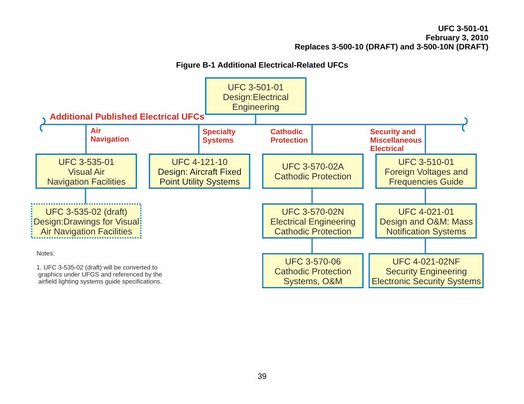
UFC 3-501-01 February 3, 2010
Replaces 3-500-10 (DRAFT) and 3-500-10N (DRAFT)
39
Figure B-1 Additional Electrical-Related UFCs
UFC 3-570-02ACathodic Protection
Air Navigation
Specialty Systems
CathodicProtection
UFC 3-570-02NElectrical EngineeringCathodic Protection
UFC 3-570-06Cathodic Protection
Systems, O&M
UFC 3-535-02 (draft)Design:Drawings for Visual
Air Navigation Facilities
UFC 3-535-01Visual Air
Navigation Facilities
Notes:
1. UFC 3-535-02 (draft) will be converted to graphics under UFGS and referenced by the airfield lighting systems guide specifications.
UFC 3-510-01Foreign Voltages andFrequencies Guide
Security andMiscellaneousElectrical
UFC 4-121-10Design: Aircraft Fixed Point Utility Systems
UFC 3-501-01Design:Electrical
Engineering
UFC 4-021-01Design and O&M: Mass
Notification Systems
UFC 4-021-02NFSecurity Engineering
Electronic Security Systems
Additional Published Electrical UFCs

UFC 3-501-01 February 3, 2010
Replaces 3-500-10 (DRAFT) and 3-500-10N (DRAFT)
40
Figure B-2 Electrical UFCs – Future Plans
UFC 3-501-01Electrical Engineering
Planned UFCsin Progress
PublishedUFCs To Be
Deleted
Planned UFCsNot Started
UFC 3-501-03N, Electrical Engineering Preliminary Design Considerations
UFC 3-540-02N, Steam Power Plants
UFC 3-550-01AF, Electrical Power Distribution
UFC 3-550-01N, Electrical Power Distribution
UFC 3-555-01N, 400 Hz Medium Voltage Conversion/Distribution and Utilization
UFC 3-540-04N, Diesel Electric Generating Plants
UFC 3-540-01, Engine Generators
UFC 3-570-01, Cathodic Protection Systems
UFC 3-575-01, Grounding/Lightning Protection
UFC 3-580-02, Exterior TelecommunicationsSystems
UFC 3-540-07, Maintenance (O&M): Engine Generators
UFC 3-550-07, Maintenance (O&M): ExteriorElectrical Power Distribution

UFC 3-501-01 February 3, 2010
Replaces 3-500-10 (DRAFT) and 3-500-10N (DRAFT
41
APPENDIX C DESIGN DATA TABLES
Table C-1 Typical Loading For Personal Computer Systems
Component Measured Load
Pentium 550 MHz Computer with Monitor 1.48A
Pentium 200 MHz Computer with Monitor 1.45A
HP LaserJet 4000 printer 0.25A idle, 5A printing
Table C-2 Load Data For Preliminary Demand Calculations
Facility Type VA/m2 VA/ft2
BEQ 21-64 2-6
Commissary/Exchange 75- 97 7-9
Cafe/Mess Hall 75-108 7-10
Administration Building 64-108 6-10
Craft/Hobby/Golf Pro 43-54 4-5
SIMA 64-108 6-10
BOQ 22-64 2-6
Warehouse/Exchange 43 4
Child Care 64 6
Chapel 54-75 5-7
Applied Instruction Building 64-108 6-10
Use the above information to aid in estimating demand for transformer sizing for preliminary calculations. As the design progresses, update demand calculations to reflect actual load of the building.

UFC 3-501-01 February 3, 2010
Replaces 3-500-10 (DRAFT) and 3-500-10N (DRAFT
42
Dwelling Unit Demand Data for Electrical Calculations Note: These Tables are provided to aid the Designer of Record in estimating the total demand for “ALL ELECTRIC” dwelling units (including diversity). Size all distribution systems for dwellings for “ALL ELECTRIC”. Use the data below for sizing distribution transformers, service lateral voltage drops and flicker calculations. These tables are not to be used for sizing the service laterals or service entrance conductors.
Table C-3 Dwelling Demand KVA per A/C Size
Table C-4 Typical A/C Size for Dwelling Units
Table C-5 Demand for Electric Strip Heat
KW Rating of Strip
KVA Demand
5 5.0
10 8.0
15 10.5
20 14.0
2 Tons 2.5 Tons 3 Tons 3.5 Tons 4 Tons # of Units
HVAC Diversity FE Total FE Total FE Total FE Total FE Total
1 1.0 3.89 6.42 4.09 7.25 4.29 8.08 4.93 9.35 5.67 10.72
2 0.85 6.61 10.91 6.95 12.33 7.29 13.74 8.38 15.9 9.64 18.22
3 0.82 8.64 14.91 9.08 16.95 9.52 18.96 10.94 21.95 12.59 25.16
4 0.80 10.27 18.37 10.8 20.91 11.33 23.45 13.02 27.16 14.97 31.13
5 0.77 11.86 21.61 12.47 24.64 13.08 27.68 15.04 32.05 17.29 36.74
6 0.75 13.3 24.69 13.99 20.21 14.67 31.73 16.86 36.75 19.39 42.12
7 0.73 14.7 27.63 15.46 31.61 16.22 35.58 18.64 41.22 21.43 47.24
8 0.72 16.2 30.76 17.01 35.22 17.85 39.68 20.51 45.97 23.59 52.68
Dwelling Type A/C (Tons) Typical (m2) Typical (ft2)
Mobile Home, Small House 2.0 93 1000
Townhouse, House 2.5 116 1250
Townhouse, Condominium 3.0 140 1500
Condo, House 3.5 163-186 1750-2000
House 4.0 186-279 2000-3000

UFC 3-501-01 February 3, 2010
Replaces 3-500-10 (DRAFT) and 3-500-10N (DRAFT
43
FE (Full Electric) is the demand value (with diversity pre-calculated) of the load without a summer (air conditioning) or winter (heat strip) HVAC mechanical load included. "Total" is the demand which includes a summer air conditioner load (Total = FE + air conditioning load). "Total" does not include the demand associated with resistive heat elements (which may drive the need for larger transformers). HVAC diversity = the diversity factor to use for winter HVAC unit demand calculations. It is incumbent of the electrical designer to address loads that are larger than those associated with the summer load. Size the transformer for the summer load unless the winter load calculation is more than 140% of the summer calculation. Example: A new underground distribution system is being designed for a housing development of duplexes. Each dwelling unit is 1500 ft2 (140 m2) with a 3-ton heat pump and 5 kW of strip heat. "Total" load for 8 dwellings (maximum 4 duplexes per transformer – See paragraph “Housing Distribution” in UFC 3-550-01) and 3 ton units = 39.68 kVA (Table C3). A check of the winter load = FE (Table C3) + # of strip units x heat strip demand (Table C5) x HVAC diversity (Table C3). Winter load = 17.85 + 8 x 5 kW x 0.72 or 46.65 kVA. Summer to Winter load ratio = 46.65/39.68 or 1.18. Size the transformer for the summer load (39.68 kVA). Thus, each 50 kVA pad-mounted transformer must feed 4 duplexes.

UFC 3-501-01 February 3, 2010
Replaces 3-500-10 (DRAFT) and 3-500-10N (DRAFT
44
APPENDIX D ELECTRICAL ENGINEERING PRELIMINARY CONSIDERATIONS
Appendix D provides the preliminary design considerations information previously contained in UFC 3-501-03N, Electrical Engineering Preliminary Considerations, which has been superseded by UFC 3-550-01. UFC 3-501-03N contained MIL-HDBK 1004/1, Electrical Engineering Preliminary Design Considerations. The original section numbers used in MIL-HDBK 1004/1 have been retained here for historical reference. The only changes made to this historical document has been formatting to better match the UFC format criteria.
Section 1: Preliminary Data 1.1 Scope. This handbook provides the criteria necessary for the proper selection of electric power sources and distribution systems. It covers preliminary load estimating factors, electrical power sources, and distribution systems. 1.2 Cancellation. This handbook cancels and supersedes DM-4.1, Electrical Engineering Preliminary Design Considerations, of December 1979, and change dated 1 March 1983. 1.3 Load Data. Before specific electric power sources and distribution systems can be considered, realistic preliminary load data must be compiled. The expected electric power demand on intermediate substations, and on the main electric power supply, shall be calculated from the connected load by applying appropriate factors. Determine these factors by load analysis and by combining loads progressively. To combine the loads, start at the ends of the smallest feeders and work back to the electric power source. Because all loads must be on a common kilowatt (kW) or kilovolt-ampere (kVA) basis, it is necessary to convert motor horsepower ratings to input kilowatts or kilovolt-amperes before combining them with other loads already expressed in those terms. Preliminary electric power load estimates can be made by using the approximate value of one kilovolt-ampere of input per horsepower (hp) at full load. Preliminary estimates of lighting loads may be made by assuming watts per ft2 (m2) of building area. 1.4 Load Analysis. To determine appropriate load estimating factors, using the tables and factors in the manual as guides analyze the characteristics of each load. Consider items such as environmental conditions of weather, geographical location, and working hours, as the situation dictates. Notice that when the load densities in w/ft2 (m2
) are used only in preliminary estimates, the demand and load factors will be used in the final designs. 1.5 Terminology. Five terms are essential to the analysis of load characteristics: demand factor, coincidence factor, diversity factor, and maximum demand. These terms are defined in paragraphs 1.5.1 through 1.5.4. 1.5.1 Demand Factor. The demand factor is the ratio of maximum demand of a system to the total connected load of the system or

UFC 3-501-01 February 3, 2010
Replaces 3-500-10 (DRAFT) and 3-500-10N (DRAFT
45
Equation: Demand factor = Maximum demand load / Total load connected (1) 1.5.2 Coincidence Factor. The coincidence factor is the ratio of the maximum demand of a system, or part under consideration, to the sum of the individual maximum demands of the subdivisions or Equation: Coincidence factor = Sum of individual maximum demands / Maximum system demand (2) 1.5.3 Diversity Factor. The diversity factor is the reciprocal of the coincidence factor or Equation: Diversity factor = Sum of individual maximum demands / Maximum system demand (3) 1.5.3 Load factor. The load factor is the ratio of the average load over a designated period of time, usually 1 year, to the maximum load occurring in that period or Equation: Load factor = Average load / Maximum load (4) 1.5.5 Maximum Demand. The maximum demand is the integrated demand for a specified time interval, i.e., 5 minutes, 15 minutes, 30 minutes, or other appropriate time intervals, rather than the instantaneous or peak demand.
Section 2: Estimation of Loads 2.1 Preparation of Load Data. Load data are generally computed in steps such as:
a) individual loads,
b) area loads, and
c) activity loads. A particular design problem may be limited to step a), to steps a) and b), or may encompass steps a), b), and c). This section outlines each step as a separate entity, dependent only on previous steps for data. Paragraphs 2.2 through 2.4.4 describe the three loads. 2.2 Individual Loads. Individual loads are those with one incoming service supplying utilization voltage to the premises. In general, these loads would comprise single structures. Large structures could contain more than one function; for example, aircraft operations, aircraft fire and rescue stations, and photographic buildings. Under this condition, factors that have been developed and keyed to Navy category codes (refer to Table 1) would be used. In this case, the factors listed under Navy category Code 141-40, 141-20, and 141-60, respectively, would be combined to obtain the total load.

UFC 3-501-01 February 3, 2010
Replaces 3-500-10 (DRAFT) and 3-500-10N (DRAFT
46
2.2.1. Lighting. To eliminate lighting loads, divide a facility area into its significant components by function (for example, office, storage, mechanical, and corridor). Determine the average lighting level and type of light source for each area. Consider requirements for supplementary lighting (for example, floodlighting, security lighting, and special task lighting). Preliminary load estimates may be made based on the following load allowances:
a) 1 W/ft2 (10.76W/m2) for each 6 to 8 fc (60 to 80 dekalux) of incandescent illumination.
b) 1 W/ft2 for each 15 to 20 fc (150 to 200 dekalux) of fluorescent illumination.
c) 1 W/ft2 for each 12 to 18 fc (120 to 180 dekalux) of mercury vapor illumination.
d) 1 W/ft2 for each 26 to 36 fc (260 to 360 dekalux) of metal halide illumination.
e) 1 W/ft2 for each 33 to 54 fc (330 to 540 dekalux) of high pressure sodium illumination.
2.2.1.1 Small Appliance Loads. Small appliance loads shall include those served by general purpose receptacles. In general, the dividing of areas by function for estimating lighting loads will serve for estimating small appliance loads. The determination of loads requires not only the knowledge of the function of an area, but to what extent its occupants use small appliances. For example, an office area demand may average about 1 W/ft2 (10.76) W/m2, but could vary from a low of 0.5 W/ft 2 (5.38 W/m2 to a high of 1.5 W/ft2, (16 W/m2) depending on the specific tasks to be performed. A minimum of 0.1 W/ft2 (1 W/m2) for auditoriums to a maximum of 2.5 W/ft2 (27 W/m2) for machine shops is possible, although the upper limit would occur very rarely. Mechanical spaces in building storage areas and similar spaces in which outlets are provided but infrequently used are usually neglected in computing loads, except for special cases.

UFC 3-501-01 February 3, 2010
Replaces 3-500-10 (DRAFT) and 3-500-10N (DRAFT
47
Table 1 Factors for Individual Facilities by Navy Category Code (See Note 1)
Navy Code
Description Demand Factor
(%)
Load Factor
(%)
100 Operational and Training Facilities:
121 Aircraft fueling/dispensing facility 40-60 16-20
122 Marine fuel dispensing 40-60 16-20
123 10 Filling station 40-60 13-17
125 16 Miscellaneous POL pipeline facilities 100 13-17
126 Liquid fueling and dispensing-other 40-60 3-7
131 Communications – buildings 60-65 70-75
131 40 Telephone exchange building 55-70 20-25
133 75 Air surveillance radar building 55-70 70-75
137 40 Port control office 55-70 20-25
141 11 Air passenger terminal building 65-80 28-32
141 20 Aircraft fire and rescue station 25-35 13-17
141 30 Aircraft line operations building 65-80 24-28
141 40 Aircraft operations building * EXC 141-70* 65-80 28-32
141 60 Photographic building 65-80 16-20
171 10 Academic instruction building 40-60 22-26
171 20 Applied instruction building 35-65 24-28
171 40 Drill Hall 75-85 3-7
200 Maintenance and Production Facilities:
211 05 Maintenance Hangar O/H space (high bay) 45-50 28-30
211 06 Maintenance Hangar – 01 space (crew equipment) 45-50 28-30
211 07 Maintenance Hangar – 02 space (administrative) 45-50 28-30
211 10 Aircraft overhaul and repair shop (NARF) 32-38 25-30
211 12 Paint/finishing hangar 65-75 25-27
211 20 Engine overhaul shop (NARF) 32-38 20-25
211 30 Aircraft/engine accessories overhaul shop (NAR) 32-38 25-30
211 75 Parachute/survival equipment 60-65 23-28
211 81 Engine test cell (Non-NARF) 42-48 25-30
211 96 Maintenance, aircraft spares storage (Miscellaneous) 58-63 23-28
212 20 Missile equipment maintenance shop 35-40 15-20
213-10 Drydock 5-10 0.5-1
214-10 Combat vehicle maintenance shop 55-65 20-25
214-20 Automobile vehicle maintenance – noncombat 55-65 20-25
215 Maintenance – weapons/spares 70-80 20-25
216 10 Ammunition rework and overhaul shop 35-40 18-22

UFC 3-501-01 February 3, 2010
Replaces 3-500-10 (DRAFT) and 3-500-10N (DRAFT
48
Navy Code
Description Demand Factor
(%)
Load Factor
(%)
216 20 Rocket rework and overhaul shop 35-40 18-22
216 30 Mines and depth charge rework shop 35-40 15-20
216 40 Torpedo shop 45-55 18-22
216 50 Special weapons shop 35-40 18-22
216 60 Quality evaluation laboratory 55-65 22-27
217 10 Electronics/communications maintenance shop 35-40 20-25
218 20 Construction/weight handling equipment shop 35-45 20-25
218 40 Railroad equipment shop 35-45 15-20
218 50 Battery shop 55-65 20-25
219 10 Public works shop 32-38 18-22
221 10 Aircraft engine assembly plant 32-38 20-25
222 10 Missile assembly buildings 35-40 15-20
222 20 Missile handling launch equipment 35-40 15-20
223 10 Fabrication/assembly building 22-27 24-29
225 10 Small arms plant 15-20 22-27
225 20 Light gun (20mm/51n) plant 15-20 22-27
225 30 Heavy gun (6/161n) plant 16-21 21-26
225 50 Launcher/projector plant 15-20 22-27
226 10 Bag charge filling plant 62-67 23-28
226 15 Case filling plant 35-40 23-28
226 20 Case overhaul tank repair facility 35-40 18-22
226 35 Major-caliber projectile loading plant 35-40 18-22
226 40 Medium-caliber projectile loading plant 35-40 18-22
226 55 Cast high explosives filling plant 35-40 18-22
226 65 Propellant and related chemical facility 30-40 32-38
227 10 Radio and radar equipment plant 50-55 23-28
227 10 Sonar equipment plant 50-55 23-28
228 10 Parachute/survival equipment plant 35-40 20-25
229 10 Asphalt plant 75-80 7-12
229 20 Concrete batching plant 75-80 15-20
229 30 Rock crusher plant 75-80 15-20
229 40 Sawmill 45-55 15-20
300 Research, Development, Test & Evaluation Facilities:
310 13 Chemistry and Toxicology Laboratory 70-80 22-28
310 15 Materials Laboratory 30-35 27-32
310 19 Physics Laboratory 70-80 22-28
316 10 Ammunition, explosives, and toxics laboratory 28-32 20-25

UFC 3-501-01 February 3, 2010
Replaces 3-500-10 (DRAFT) and 3-500-10N (DRAFT
49
Navy Code
Description Demand Factor
(%)
Load Factor
(%)
317 20 Electrical and electronics systems laboratory 20-30 3-7
400 Supply Facilities:
421 Ammunition storage installation 75-80 …..
423 Ammunition storage-liquid propellant 75-80 20-25
431 10 Cold storage warehouse 70-75 20-25
441 10 General warehouse Navy 75-80 23-28
441 20 Controlled humidity warehouse 60-65 33-38
441 30 Hazardous/ flammable storehouse 75-80 20-25
441 40 Underground storage 65-70 23-28
441 70 Disposal, salvage, scrap building 35-40 25-20
500 Hospital-Medical Facilities:
510 10 Hospital 38-42 45-50
530 20 Laboratory 32-37 20-25
540 10 Dental Clinic 35-40 18-23
550 10 Medical Clinic 45-50 20-23
600 Administrative Facilities:
610 10 Administrative Office 50-65 20-35
620 10 Administrative facility, underground 50-65 35-40
700 Housing and Community Facilities:
711 Family housing-dwellings 60-70 10-15
712 Substandard: Trailers - family housing 70-75 10-15
714 10 Detached garages 40-50 2-4
721 11 Bachelor enlisted quarters 35-40 38-42
721 12 Bachelor enlisted quarters E5/E6 35-40 38-42
721 13 Bachelor enlisted quarters E7/E9 35-40 38-42
721 30 Civilian barracks GS 01/6 35-40 38-42
721 40 Disciplinary barracks 35-40 38-42
722 10 Detached dining facilities, enlisted men 30-35 45-60
723 20 Latrine, detached 75-80 20-25
723 30 Laundry, detached 30-35 20-25
723 40 Garage, detached 40-50 2-4
724 11 UOPH, W-1/0-2 40-50 20-25
724 12 UOPH, 0-3 and above 40-50 20-25
724 22 Civilian quarters, GS-7/PLS 40-50 20-25
724 30 Dining facility (attached) commissioned personnel 35-40 30-40
730 10 Fire station 25-35 13-17
730 15 Confinement facility 60-65 33-38

UFC 3-501-01 February 3, 2010
Replaces 3-500-10 (DRAFT) and 3-500-10N (DRAFT
50
Navy Code
Description Demand Factor
(%)
Load Factor
(%)
730 20 Police station 48-53 20-25
730 25 Gate/sentry house 70-75 28-33
730 30 Bakery 30-35 45-60
730 35 Enlisted personnel locker room 75-80 18-23
730 40 Laundry/dry cleaning plant 30-35 20-25
730 45 Dependent school – nursery school 75-80 10-15
730 50 Dependent school – kindergarten 75-80 10-15
730 55 Dependent school – grade school 75-80 10-15
730 60 Dependent school – high school 65-70 12-17
730 65 Fallout shelter 80-85 30-35
730 67 Bus station 80-85 30-35
730 70 Decontamination facility 75-80 15-2
730 83 Chapel 65-70 5-25
730 85 Post Office 75-80 20-25
740 01 Exchange retail store 65-70 25-32
740-18 Bank 75-80 20-25
740 23 Commissary including backup storage 55-60 25-30
740 26 Installation restaurant 45-75 15-25
740 30 Exchange auto repair station 40-60 15-20
740 36 Hobby shop, art/crafts 30-40 25-30
740 40 Bowling Alley 70-75 10-15
740 43 Gymnasium 70-75 20-45
740 46 Skating rink 70-75 10-15
740 50 Field house 75-80 7-12
740 53 Indoor swimming pool 55-60 25-50
740 56 Theater 45-55 8-13
740 60 Commissioned officers’ mess, open 55-60 15-20
740 63 Enlisted personnel club 55-60 18-23
740 66 Petty officers’ mess, open 55-60 18-23
740 70 Mess open, E-7 through E-9 55-60 15-20
740 76 Library 75-80 30-35
740 80 Golf club house 75-80 15-20
740 86 Exchange installation warehouse 58-63 23-28
740 88 Educational services office 70-75 30-35
760 10 Museum/memorial building 75-80 30-35
800 Utilities and Ground Improvements:
811 10 Electric power plant-diesel 60-65 58-63

UFC 3-501-01 February 3, 2010
Replaces 3-500-10 (DRAFT) and 3-500-10N (DRAFT
51
Navy Code
Description Demand Factor
(%)
Load Factor
(%)
811 25 Electric power plant-steam 60-65 58-63
811 45 Electric power plant-gas turbine 60-65 58-63
811 60 Standby generator plant 75-80 5-10
812 20 Street lighting 95-… 46-…
812 40 Perimeter/security lighting 80-85 22-27
813 20 Substation, more than 499 kV 25-30 20-25
821 12 Fossil fuel heating plant – medium 55-60 30-60
821 22 Fossil fuel heating plant – large 55-60 30-60
821 50 Non-nuclear steam plant 50-55 30-40
826 20 Chilled water plant 25/100 tons 60-70 25-30
827 20 Air conditioning-chilled water transmission/distribution system – medium (25/100 tons)
60-70 25-30
831 10 Combination sewage and industrial waste treatment plant 60-70 15-20
832 30 Sewage-industrial waste pumping station 55-60 30-35
833 22 Incinerator building and incinerator 55-60 15-20
841 10 Water treatment facilities 60-80 15-25
841 50 Wells-potable water 60-80 15-25
843 20 Fire protection pumping station Do not include – operate
for test off peak.
890 20 Compressed air plant 45-50 25-30
890 42 Air-conditioning plant 60-70 25-30
Miscellaneous Operational and Training Facilities:
125 10 POL pipeline
132 10 Antenna – communications 95-… 46-…
Miscellaneous Facilities for Ship Repair and Shipbuilding:
Ship repair shops:
213 41 Central tool shop – (06) (E) 32-37 23-28
213 42 Shipfitting shop – (11) (A) 22-27 24-29
213 43 Sheet metal ship (17) (B) 10-15 15-20
213 44 Forge and heat treatment space (23) (F) 25-30 13-18
213 49 Inside machine shop – (31) (G) 16-21 21-26
213 53 Boiler making shop – (41) (D) 12-17 14-19
213 54 Electrical shop – (51) (M) 33-38 20-25
213 55 Pipefitting shop – (56) (J) 22-27 17-22
213 56 Woodworking shop – (64) (R) 25-30 21-26
213 59 Abrasive blast facility 30-35 10-15
213 60 Paint and blasting shop – (71) (S) 50-55 23-28
213 61 Riggers shop – (72) (T) 50-55 20-25

UFC 3-501-01 February 3, 2010
Replaces 3-500-10 (DRAFT) and 3-500-10N (DRAFT
52
Navy Code
Description Demand Factor
(%)
Load Factor
(%)
213 62 Sail loft 35-40 20-25
213 63 Foundry – (81) (K) 35-40 22-27
213 64 Patternmaking shop – (94) (X) 28-33 12-17
213 67 Pumphouse, drydocks 75-80 0.1-0.2
Miscellaneous Facilities for Naval Ordnance Manufacture:
226 Ammunition components building 15-20 20-25
226 Manufacturing 30-45 17-32
226 Explosive loading 65-70 25-30
226 Miscellaneous explosives storage and handling 65-70 5-10
226 Assembly building 40-50 20-25
226 Detonator building 65-70 20-25
226 Pelleting 40-50 20-25
226 Plastic beading 55-60 18-23
226 Sewing room 35-40 25-30
226 Projective assembly breakdown 55-60 18-23
226 Machine shop 16-21 21-26
226 Phosphorous plant 35-40 25-30
226 TNT detonator (military) 35-40 15-20
226 Ammunition tank box assembly 35-40 15-20
226 Box emptying 35-40 15-20
226 Plating maintenance 35-40 18-23
226 Mixing 40-45 18-23
226 Segregation fleet return 35-40 15-20
226 Plaster load 35-40 15-20
Fluoroscope building 45-50 18-23
Tank building rocket 40-45 15-20
Hydrostatic test 35-40 15-20
Phosphorous loading 35-40 15-20
226 Vacuum and hydraulic pump building 35-40 12-17
226 Cable drive 35-40 12-17
226 Dryer building 75-80 3-8
Miscellaneous Production Facilities:
229 50 Printing Plant 45-55 25-30
Miscellaneous Storage Facilities:
750 Community Facilities – morale, welfare, and recreation – exterior
Determine by load count and time.
750 30 Outdoor swimming pool installation 80-85 20-25
750 54 Band stand 75-80 15-25

UFC 3-501-01 February 3, 2010
Replaces 3-500-10 (DRAFT) and 3-500-10N (DRAFT
53
Navy Code
Description Demand Factor
(%)
Load Factor
(%)
Miscellaneous Facilities for Utilities and Ground Improvements:
821 09 Heating plant building (condensate) 55-60 25-40
821 09 Heating plant building (heating) 55-60 30-35
833 40 Garbage house 75-80 20-25
841 Potable water – supply/treatment/storage Determine by load
count and time.
845 20 Pipeline nonpotable water 55-60 3-8
852 30 Pedestrian bridge 80-85 20-25
872 20 Guard and watch towers 80- 46-
890 20 Compressed air plant 60-65 20-25
Note 1: Demand factors include allowance for system loss. 2.2.1.2 Electric Power Loads. Electric power loads shall include all loads other than lighting loads and those served by general purpose receptacles and comprise the environmental system electric power requirements and the facility occupancy equipment electric power requirements. 2.2.1.3 System Loss. A system loss of approximately 6 percent, based on calculated maximum demand, should be added to the building load. 2.2.2 Demand and load factors. The demand and load factors for a specific facility will vary with the division of load and hours of usage. Refer to Tables 2 and 3 for values that can be applied to determine demand and load factors. Table 4 is included as a guide and an aid in illustrating the method of determining loads, which are calculated for a particular type of building, such as an academic and general instruction building (Navy Code 171-10). The values given are empirical and will vary from activity to activity, and may vary from one facility to another within an activity. Annual hours use of demand must be determined for each case in accordance with methods of operation and characteristics of the installation. Demand factors and load factors for individual facilities by the Navy category code given in Table 1 are based on a survey of existing Navy facilities and past experience. Such factors should be used for quick estimating purposes and as a check when a more precise calculation is undertaken (refer to Table 4). 2.2.2.1 Guides for Demand Factors. For guides on selection of demand factors, refer to Table 5. 2.2.2.2 Guides for Load Factors. Guides for the selection of load factors indicate the need for special considerations (refer to Table 6). Factors in the middle of the range are for the average facility at the peacetime shore establishment and should be used unless the guides in Table 6 indicate otherwise.

UFC 3-501-01 February 3, 2010
Replaces 3-500-10 (DRAFT) and 3-500-10N (DRAFT
54
2.2.3 Load Growth. Determine the requirements for load growth for anticipated usage and life expectancy with particular attention to the possibility of adding heavy loads in the form of air conditioning, electric heating, electric data processing and electronic communication equipment. Before determining the size of service and method of distribution to a facility, an economic analysis shall be made to determine the most feasible way of serving this future load. This analysis shall include the effect on the existing installation if future loads require reinforcing or rehabilitation of the service system.
Table 2 Demand Factors for Specific Loads (See Note 1)
Types of Loads Estimated Range of Demand Factor
(%)
Quick Estimating Demand Factor
(%)
Motors: General purpose, machine tool, cranes, elevators, ventilation, compressors, pumps, etc
20–100 30
Motors: Miscellaneous, fractional, and small appliances
10–50 25
Resistance ovens, heaters, and furnaces 80–100 80
Induction furnaces 80–100 80
Lighting 65–100 75
Arc welders 25–50 30
Resistance welders 5–40 20
Air-conditioning equipment 60–100 70
Refrigeration compressors 40–100 60
Note 1: Demand factors include allowance for system loss.

UFC 3-501-01 February 3, 2010
Replaces 3-500-10 (DRAFT) and 3-500-10N (DRAFT
55
Table 3 Annual Hours of Demand Usage for Specific Loads
Quick Estimating Hours of Use Types of Loads
1-Shift Operation
2-Shift Operation
3-Shift Operation
Motors: General purpose
1,200 1,600 2,000
Motors: Miscellaneous, fractional, and small appliances
1,500 1,800 2,100
Resistance ovens, heaters, and furnaces 1,000 1,300 1,600
Induction furnaces 900 1,200 1,500
Lighting 2,200 2,800 3,500
Arc welders 500 700 900
Resistance welders 500 700 900
Air-conditioning equipment
Less than 1,500 cooling degree days 1,200 1,400 1,600
1,500 to 2,500 cooling degree days 1,600 1,800 2,000
More than 2,500 cooling degree days 2,200 2,500 2,800
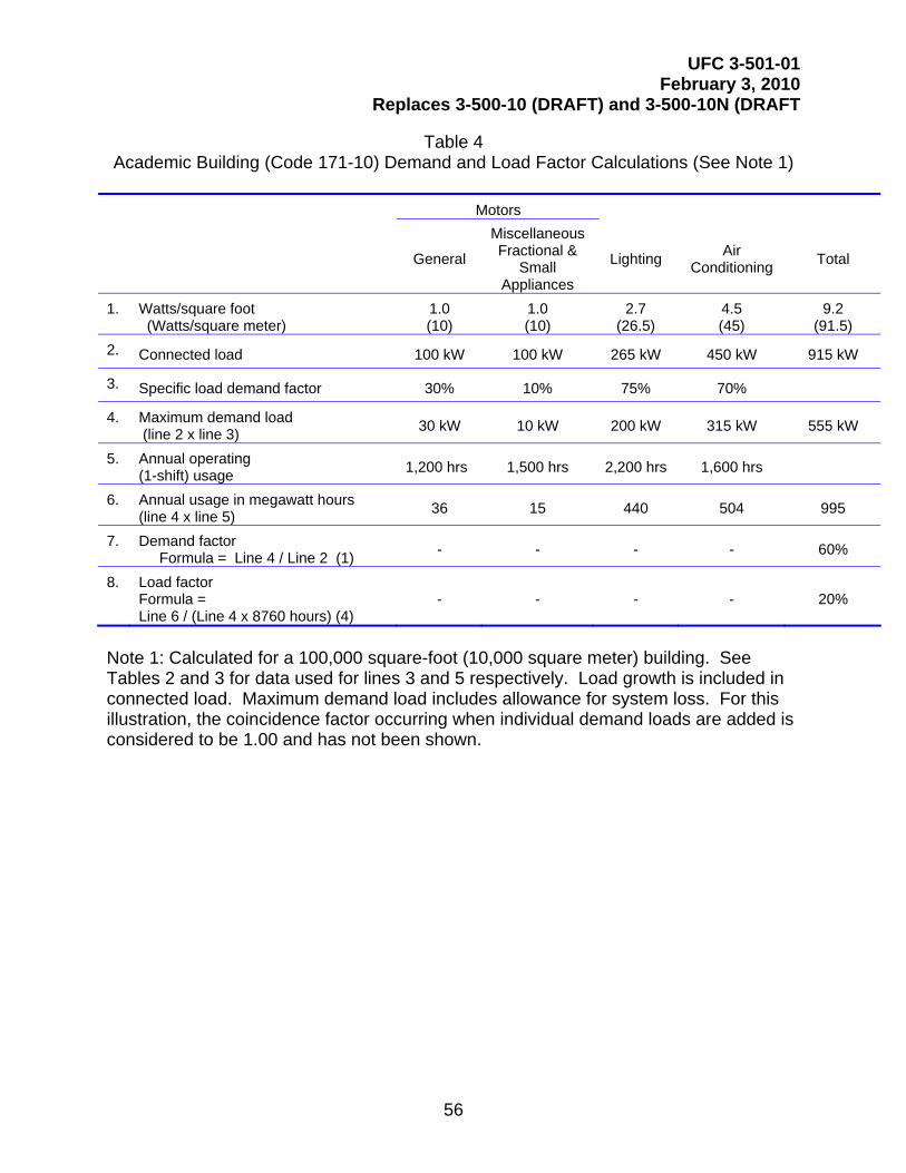
UFC 3-501-01 February 3, 2010
Replaces 3-500-10 (DRAFT) and 3-500-10N (DRAFT
56
Table 4 Academic Building (Code 171-10) Demand and Load Factor Calculations (See Note 1)
Motors
General
Miscellaneous Fractional &
Small Appliances
Lighting Air
Conditioning Total
1. Watts/square foot (Watts/square meter)
1.0 (10)
1.0 (10)
2.7 (26.5)
4.5 (45)
9.2 (91.5)
2. Connected load 100 kW 100 kW 265 kW 450 kW 915 kW
3. Specific load demand factor 30% 10% 75% 70%
4. Maximum demand load (line 2 x line 3)
30 kW 10 kW 200 kW 315 kW 555 kW
5. Annual operating (1-shift) usage
1,200 hrs 1,500 hrs 2,200 hrs 1,600 hrs
6. Annual usage in megawatt hours (line 4 x line 5)
36 15 440 504 995
7. Demand factor Formula = Line 4 / Line 2 (1)
- - - - 60%
8. Load factor Formula = Line 6 / (Line 4 x 8760 hours) (4)
- - - - 20%
Note 1: Calculated for a 100,000 square-foot (10,000 square meter) building. See Tables 2 and 3 for data used for lines 3 and 5 respectively. Load growth is included in connected load. Maximum demand load includes allowance for system loss. For this illustration, the coincidence factor occurring when individual demand loads are added is considered to be 1.00 and has not been shown.

UFC 3-501-01 February 3, 2010
Replaces 3-500-10 (DRAFT) and 3-500-10N (DRAFT
57
Table 5 Guides for Selection of Demand Factors
Select factors in upper half of range for conditions described below
Select factors in lower half of range for conditions described below
GENERAL GUIDES
Facilities in active use and approaching maximum capacity.
Loads predominantly lighting. Loads predominantly heating. Loads dominated by one or two large motors.
Facilities of intermittent use or not being fully utilized.
Motor loads made up of a number of independently operated small motors.
Motor loads controlled automatically unless control depends upon weather conditions.
OPERATIONAL AND TRAINING FACILITIES Instruction buildings with little or no electric
equipment. Communications buildings with telephonic
equipment only.
Large instruction buildings with electrical demonstration and training equipment.
MAINTENANCE AND PRODUCTION FACILITIES Shops and facilities when engaged in mass
production of similar parts. No special guides.
RESEARCH, DEVELOPMENT, AND TEST FACILITIES Facilities used for repetitive testing of material or
equipment. No special guides.
SUPPLY FACILITIES Refrigerated warehouses in South. Dehumidified warehouses in Mississippi Valley and
along seacoasts. Warehouses for active storage.
Warehouses with many items of electric materials handling equipment, including cranes and elevators.
HOSPITAL AND MEDICAL FACILITIES No special guides. No special guides.
ADMINISTRATIVE FACILITIES Large administrative buildings with mechanical
ventilation and air conditioning. Note: Group large administrative buildings
separately only when administration is a significant part of total activity load.
Casual offices, offices used infrequently by foremen and supervisors, or offices in which there is little prolonged desk work.
HOUSING AND COMMUNITY FACILITIES Enlisted barracks at training centers. Public quarters where less than 25 family units are
involved. Restaurants, exchanges, cafeterias, and other food
service facilities when gas or steam is primary fuel.
Food service facilities where load is primarily cooking and baking.
UTILITIES AND GROUND IMPROVEMENTS Central heating plants serving extended areas and
buildings. Water pumping stations serving extended areas or
carrying most of load of water systems. Central station compressed air plants.
No special guides.

UFC 3-501-01 February 3, 2010
Replaces 3-500-10 (DRAFT) and 3-500-10N (DRAFT
58
Table 6 Guides for Selection of Loads Factors
Select factors in upper half of range for conditions described below
Selection factors in lower half of range for conditions described below
GENERAL GUIDES Facilities operated on two or more shifts. Loads that are primarily fluorescent or high
intensity discharge lighting. Many small independently operated motors. Electronic equipment continuously operated for
immediate use. Cooling and dehumidification loads for year-
round climate control in southern climates. Retail-type service loads and loads that are in
active use.
Facilities used intermittently. Inactive facilities. Large motor loads when the load consists of relatively small
numbers of motors. Wholesale-type service facilities.
OPERATIONAL AND TRAINING FACILITIES Large, permanent instruction buildings in active
use. Special-purpose instruction and training facilities not
regularly used. MAINTENANCE AND PRODUCTION FACILITIES
Shops with battery charging equipment operated after hours.
Active shops at full employment. Mass production shops.
Welding loads or loads made up primarily of welding equipment.
Job-order workshops. Shops with large, heavy special function machines. Large induction or dielectric heating loads.
RESEARCH, DEVELOPMENT, AND TEST FACILITIES No special guides. No special guides.
SUPPLY FACILITIES Refrigerated and dehumidified warehouses in
South or in humid climates. Warehouses for active storage and in
continuous use.
Refrigerated warehouses in North. Warehouses with large materials handling equipment loads.
HOSPITAL AND MEDICAL FACILITIES Clinics and wards with daily operating hours
and in active use. No special guides.
ADMINISTRATIVE FACILITIES Large, active, well-lighted offices with
ventilation and air-conditioning equipment. No special guides.
HOUSING AND COMMUNITY FACILITIES Navy exchanges with food service facilities. Gymnasiums used in connection or with
physical therapy. Barracks at schools and training centers.
Restaurants and exchanges serving only one meal a day. Restaurants and exchanges with gas steam food
preparation equipment. Chapels used primarily on Sundays. Subsistence buildings serving less than four meals a day. Laundries with dry cleaning plants. Exchanges operated less than 8 hrs/day Gatehouses operated less than 24 hrs/day
UTILITIES AND GROUND IMPROVEMENTS Heating plants that supply both heating and
process steam. Water plants with little power load. Air-conditioning plants for year-round control of
environment in South. Compressed air plants consisting of many
banked compressors operating automatically.
Heating plants in South.

UFC 3-501-01 February 3, 2010
Replaces 3-500-10 (DRAFT) and 3-500-10N (DRAFT
59
2.2.4 Emergency Loads. The determination of emergency electric power requirements is based on three types of loads (refer to Section 3 for types of loads to be included in each category): Minimum essential load,
Emergency load for vital operations, and
Uninterruptible (no-break) load. When the three categories of emergency electric power requirements have been ascertained, determine where local emergency facilities are required, where loads may be grouped for centralized emergency facilities, and what loads are satisfied by the reliability of the general system. Base the aforementioned determinations on safety, reliability, and economy, in that order. 2.3 Area Loads. Area loads consist of groups of individual facility loads served by a subdivision of the electric distribution system. The term “area” applies to the next larger subdivision of an overall distribution system. Demand loads for an area must be known for sizing the distribution wiring and switching, and in a large installation will be required for the design of substations serving the area. Table 7 gives an example of how the coincident peak demand is calculated. 2.3.1 General Loads. To obtain the general load, add roadway lighting, area lighting, obstruction lighting, and other loads not included in individual facility loads. 2.3.2 Coincidence Factor. Determine the maximum expected demands, taking into consideration whether loads within the area peak at the same or at different times. 2.3.2.1 Relationships. Figure 1 indicates the relationship that exists between the load factor of individual facility loads and the coincidence of their peak demands with the peak demand of the group. This relationship was developed by a study of the loads of selected naval shore activities and by the application of factors developed to the formulas published by IEEE. For collateral reading on this subject, refer to IEEE Technical Paper 45-116 Coincidence-Factor Relationship of Electric Service Load Characteristics. Table 8 is Figure 1 in tabular form with values shown to the nearest whole dollar, except for low load factors. 2.3.2.2 Selection. Areas with relatively insignificant residential type loads, where the load curve indicates that most of the electric power consumed in the area is used during the 40 normal working hours of a week, have coincidence factors at the higher end of the range. 2.3.2.3 Electric Power Consumption. In general, areas where large amounts of electric power are consumed outside the usual 40 working hours a week have a coincidence factor at the lower end of the range (examples are hospitals, areas operated on two or more shifts, or large barracks type activities). The upper limit of the range is for the 40 hour per week operation; the lower limit is for a 60 hour per week operation.

UFC 3-501-01 February 3, 2010
Replaces 3-500-10 (DRAFT) and 3-500-10N (DRAFT
60
Table 7 Method of Calculating Coincident Peak Demand
Parenthesized ( ) numbers refer to Notes
Navy Code
Description
Total Connected Load (kW)
Demand Factor
(%)
Maximum Demand
(%)
Load Factor
(%)
Coincidence Factor
(%)
Coincidence Peak (kW)
125 16 Fuel oil pump house
125 16 Fuel oil pump house
125 16 Total 0.3 100 0.3 52 52(1) 0.2
125 20 Filling station 3.0 60 1.8 18 57(1) 1.0
125 20 Filling station building 0.3 80 0.2 20 61(1) 0.1
131 35 Receiver building 2.1 65 1.4 72 79 1.1
131 50 Transmitter building
131 50 Transmitter building
131 50 Total 37.2 65 24.2 72 79 19.1
133 25 Tacan building 0.7 65 0.5 72 79 0.4
133 75 Radar building 1.2 70 0.8 72 79 0.6
141 20 Aircraft fire and rescue station 8.0 30 2.4 15 52(1) 1.2
141 40 Aircraft operations building 80.2 80 64.2 28 68(1) 43.6
141 60 Photographic building 10.5 70 7.4 18 57(1) 4.2
171 10 Academic instruct building
171 10 Academic instruct building
171 10 Academic instruct building 171 10 Academic instruct building 171 10 Total 47 60 28.2 22 62(1) 17.5 171 35 Operational Trainer Facility 0.1 80 0.1 15 52(1) ……… 211 10 Aircraft overhaul and repair shop 7,600 38 2,890 25 95(2) 2,745 211 12 Paint/finishing hangar 127 70 89.0 26 66(1) 58.3 211 22 Engine preparation and storage shop 211 21 Engine maintenance shop

UFC 3-501-01 February 3, 2010
Replaces 3-500-10 (DRAFT) and 3-500-10N (DRAFT
61
Navy Code
Description
Total Connected Load (kW)
Demand Factor
(%)
Maximum Demand
(%)
Load Factor
(%)
Coincidence Factor
(%)
Coincidence Peak (kW)
211 21 Engine maintenance shop 211 21 Total 405 40 162 15 52(1) 84.2 211 83 Engine test cell 360 45 162 28 68(1) 110 212 20 Missile equipment maintenance shop 3.0 40 1.2 22 62(1) 0.7 214 20 Auto vehicle maintenance facilities 214 20 Auto vehicle maintenance facilities 214 20 Auto vehicle maintenance facilities 214 20 Auto vehicle maintenance facilities 214 20 Total 370 60 222 25 65(1) 145 730 10 Fire station 14.6 30 4.4 15 521 2.3
Total 3,325 System loss (6%) 194
Grand total 3,429
(1) The coincidence factor has been increased to allow for low load factor and number of facilities in the area. Refer to
paragraph 2.3.2.4, Influencing Factors, of this handbook. (2) The coincidence factor has been increased because of the relative magnitude of the load. Refer to paragraph 2.3.2.5,
Individual Loads, of this handbook.

UFC 3-501-01 February 3, 2010
Replaces 3-500-10 (DRAFT) and 3-500-10N (DRAFT
62
Figure 1
Theoretical Relationship between Load Factor and Coincidence Factor at U.S. Naval Shore Establishments

UFC 3-501-01 February 3, 2010
Replaces 3-500-10 (DRAFT) and 3-500-10N (DRAFT
63
Table 8 Relationship between Load Factor and Coincidence Factor
Coincidence Factor (%)
Loads (hr/wk) Coincidence Factor (%)
Loads (hr/wk) Load Factor
(%) 40 60
Load Factor %
40 60 1 2.5 1.5 51 73 69 2 7.5 4.5 52 73 70 3 12 8 53 73 70 4 17 11 54 73 70 5 21 14 55 73 71 6 25 17 56 73 71 7 28 20 57 73 71 8 32 22 58 74 71 9 35 24 59 74 72
10 38 26 60 74 72 11 41 29 61 74 72 12 44 32 62 75 73 13 46 34 63 75 73 14 49 36 64 76 74 15 51 38 65 76 74 16 53 40 66 77 75 17 54 42 67 77 75 18 56 44 68 78 76 19 57 46 69 78 76 20 59 48 70 78 77 21 60 50 71 78 77 22 61 51 72 79 78 23 62 53 73 79 78 24 63 54 74 80 79 25 64 55 75 81 80 26 65 56 76 81 80 27 66 56 77 82 81 28 67 57 78 82 81 29 68 58 79 82 81 30 69 59 80 82 82 31 69 60 81 82 82 32 69 61 82 82 82 33 70 62 83 83 83 34 70 63 84 84 84 35 71 64 85 85 85 36 71 64 86 86 86 37 71 65 87 87 87 38 71 65 88 88 88 39 72 65 89 89 89 40 72 66 90 90 90 41 72 66 91 91 91 42 72 66 92 92 92 43 72 67 93 93 93 44 73 67 94 94 94 45 73 67 95 95 95 46 73 67 96 96 96 47 73 68 97 97 97 48 73 68 98 98 98 49 73 69 99 99 99 50 73 69 100 100 100

UFC 3-501-01 February 3, 2010
Replaces 3-500-10 (DRAFT) and 3-500-10N (DRAFT
64
2.3.2.4 Influencing Factors. The number of individual loads in a group and their load factors influence the individual load coincidence factor. The coincidence factors in table 8 apply for groups of 100 or more individual loads. These coincidence factors can also be used for groups of as few as 30 to 50 individual loads if their load factor is 0.30 of greater. For areas of fewer individual loads, the mathematical relationship from IEEE Technical Paper 45-116 provides a basis for estimating the connected coincidence factor as shown by the following equation: Equation: En = Et + (1 – Et)1/n (5) where: En = The individual load coincidence factor applied with a given number of
consumers. Et = The coincidence factor as given in Table 8 in hundredths. n = The number of individual loads in a group. 2.3.2.5 Individual loads. The coincidence factors in Table 8 are based on the individual loads in a group being substantially the same size. If a single load or small group of loads in an area represent a substantial percentage of overall load, the coincidence factors as given in Table 8 will no longer apply. With an individual load, increase the coincidence factor to a value commensurate with its effect on the overall area load. This is not in addition to, but in place of, the normal coincidence factor. Determine this value by considering intergroup coincidence factors given in paragraph 2.3.2. 2.3.2.6 An example of facility Navy Code 211-70 is presented in Table 7. For a small group, determine the coincidence peak load, and to this apply the appropriate intergroup coincidence factor to obtain the coincidence peak load for the area. 2.3.2.7 Groups of Loads or Areas. Where groups of loads within an area, or areas within a facility are combined, an additional intergroup coincidence factor will exist. For loads of similar nature, the intergroup coincidence factor should be in the range 0.93 to 1.00. If loads of a varying nature (evening loads and daytime loads) are combined, the intergroup coincidence factor should be in the range of 0.70 to 1.00. The lower values will occur when magnitudes of the loads are nearly balanced, and the higher ones when the combined load is predominantly one type. 2.3.3 Load Growth. In addition to planned expansion, increased application of electric equipment will generate an increase in load. When sizing components, such as transformers or feeders for the area system, consider possible load growth in addition to that included in determination of individual loads. 2.3.4 System Losses. Add distribution system losses to estimated area demands. For a good approximation, use 6 percent of the calculated maximum demand.

UFC 3-501-01 February 3, 2010
Replaces 3-500-10 (DRAFT) and 3-500-10N (DRAFT
65
2.3.5 Emergency Loads. Review the overall emergency requirements for the area, based on criteria for the facility or as furnished by the using agency, to determine the following: a) The emergency loads that may be combined in groups to take advantage of the coincidence factor. b) The type of distribution system needed for reliability and to economically satisfy at least the less critical emergency load requirements. This reliability can be provided only if the source of electric power is not the determining factor. c) Area loads that must be added to individual emergency loads; for example, security lighting and minimum roadway lighting. 2.3.6 Expansion. The planned development of the area, as shown on the activity general development map, shall be considered for requirements of future expansion. 2.4 Activity Loads. Activity Loads are loads that consist of two or more area loads served from a single electric power source and an integrated distribution system. 2.4.1 General Loads. Follow the approach used in paragraph 2.3 for area loads. Area loads used for determining activity coincidence demand should be the area coincident demand exclusive of allowance for load growth. 2.4.2 Coincidence Factor. Refer to paragraph 2.3.2 for the necessary approach. Where dissimilar areas, whether residential, administrative, or industrial, are part of an activity, make a careful analysis of the coincidence factor used. 2.4.3 Load Growth. As for an area, components should be sized after due consideration has been given to load growth. Apply this increase to the coincident demand of the activity. 2.4.4 Expansion. The planned development of the activity, as shown on its general development map, shall be considered for requirements of future expansion.