Embed Size (px)
Citation preview
8/4/2019 Unified Facilities Criteria (Ufc) for Compressed Air
http://slidepdf.com/reader/full/unified-facilities-criteria-ufc-for-compressed-air 1/23
UFC 3-420-02FA15 May 2003
Including change 1, December 2007
UNIFIED FACILITIES CRITERIA (UFC)
COMPRESSED AIR
APPROVED FOR PUBLIC RELEASE; DISTRIBUTION UNLIMITED
8/4/2019 Unified Facilities Criteria (Ufc) for Compressed Air
http://slidepdf.com/reader/full/unified-facilities-criteria-ufc-for-compressed-air 2/23
UFC 3-420-02FA15 May 2003
Including change 1, December 2007
1
UNIFIED FACILITIES CRITERIA (UFC)
COMPRESSED AIR
Any copyrighted material included in this UFC is identified at its point of use.Use of the copyrighted material apart from this UFC must have the permission of thecopyright holder.
U.S. ARMY CORPS OF ENGINEERS (Preparing Activity)
NAVAL FACILITIES ENGINEERING COMMAND
AIR FORCE CIVIL ENGINEER SUPPORT AGENCY
Record of Changes (changes are indicated by \ 1 \ ... / 1 /)
Change No. Date Location1 Dec 2007 Page 1-1, Chapter , Para 1-4a., add (7)
This UFC supersedes TM 5-810-4, dated 12 January 1990. The format of this UFC does notconform to UFC 1-300-01; however, the format will be adjusted to conform at the next revision.The body of this UFC is a document of a different number.
8/4/2019 Unified Facilities Criteria (Ufc) for Compressed Air
http://slidepdf.com/reader/full/unified-facilities-criteria-ufc-for-compressed-air 3/23
UFC 3-420-02FA15 May 2003
Including change 1, December 2007
2
FOREWORD \1\ The Unified Facilities Criteria (UFC) system is prescribed by MIL-STD 3007 and providesplanning, design, construction, sustainment, restoration, and modernization criteria, and appliesto the Military Departments, the Defense Agencies, and the DoD Field Activities in accordance
with USD(AT&L) Memorandum dated 29 May 2002. UFC will be used for all DoD projects andwork for other customers where appropriate. All construction outside of the United States isalso governed by Status of forces Agreements (SOFA), Host Nation Funded ConstructionAgreements (HNFA), and in some instances, Bilateral Infrastructure Agreements (BIA.)Therefore, the acquisition team must ensure compliance with the more stringent of the UFC, theSOFA, the HNFA, and the BIA, as applicable.
UFC are living documents and will be periodically reviewed, updated, and made available tousers as part of the Services’ responsibility for providing technical criteria for militaryconstruction. Headquarters, U.S. Army Corps of Engineers (HQUSACE), Naval FacilitiesEngineering Command (NAVFAC), and Air Force Civil Engineer Support Agency (AFCESA) areresponsible for administration of the UFC system. Defense agencies should contact the
preparing service for document interpretation and improvements. Technical content of UFC isthe responsibility of the cognizant DoD working group. Recommended changes with supportingrationale should be sent to the respective service proponent office by the following electronicform: Criteria Change Request (CCR). The form is also accessible from the Internet sites listedbelow.
UFC are effective upon issuance and are distributed only in electronic media from the followingsource:
• Whole Building Design Guide web site http://dod.wbdg.org/ .
Hard copies of UFC printed from electronic media should be checked against the currentelectronic version prior to use to ensure that they are current.
AUTHORIZED BY:
______________________________________ DONALD L. BASHAM, P.E.Chief, Engineering and ConstructionU.S. Army Corps of Engineers
______________________________________ DR. JAMES W WRIGHT, P.E.Chief EngineerNaval Facilities Engineering Command
______________________________________ KATHLEEN I. FERGUSON, P.E.The Deputy Civil EngineerDCS/Installations & LogisticsDepartment of the Air Force
______________________________________ Dr. GET W. MOY, P.E.Director, Installations Requirements and
ManagementOffice of the Deputy Under Secretary of Defense
(Installations and Environment)
8/4/2019 Unified Facilities Criteria (Ufc) for Compressed Air
http://slidepdf.com/reader/full/unified-facilities-criteria-ufc-for-compressed-air 4/23
ARMY TM 5-810-4AIR FORCE AFM 88-8, Chap. 3
COMPRESSED AIR
DEPARTMENTS OF THE ARMY, AND THE AIR FORCE
12 JANUARY 1990

8/4/2019 Unified Facilities Criteria (Ufc) for Compressed Air
http://slidepdf.com/reader/full/unified-facilities-criteria-ufc-for-compressed-air 5/23
REPRODUCTION AUTHORIZATION/RESTRICTIONS
This manual has been prepared by or for the Government and, except to the extent
indicated below, is public property and not subject to copyright.
Copyrighted material included in the manual has been used with the knowledge and
permission of the proprietors and is acknowledged as such at point of use. Anyone
wishing to make further use of any copyrighted material, by itself and apart from this
text, should seek necessary permission directly from the proprietors.
Reprints or republications of this manual should include a credit substantially as
follows: "Joint Departments of the Army and Air Force, USA, Technical Manual TM
5-810-4/AFM 88-8, Chapter 3. Compressed Air, 12 January 1990.”
If the reprint or republication includes copyrighted materials, the credit should also
state: "Anyone wishing to make further use of copyrighted material, by itself and
apart from this text, should seek necessary permission directly from the proprietors.”
8/4/2019 Unified Facilities Criteria (Ufc) for Compressed Air
http://slidepdf.com/reader/full/unified-facilities-criteria-ufc-for-compressed-air 6/23
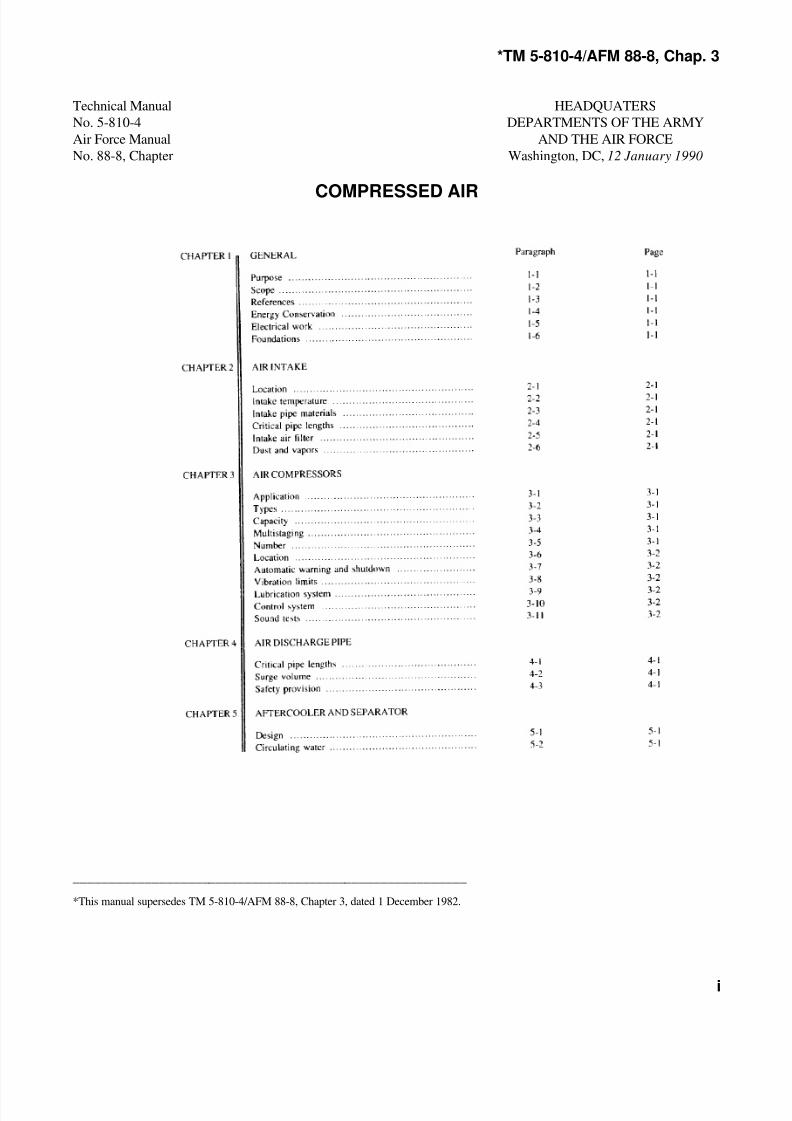
*TM 5-810-4/AFM 88-8, Chap. 3
i
Technical Manual HEADQUATERS
No. 5-810-4 DEPARTMENTS OF THE ARMY
Air Force Manual AND THE AIR FORCE
No. 88-8, Chapter Washington, DC, 12 January 1990
COMPRESSED AIR
_______________________________________________________
*This manual supersedes TM 5-810-4/AFM 88-8, Chapter 3, dated 1 December 1982.
8/4/2019 Unified Facilities Criteria (Ufc) for Compressed Air
http://slidepdf.com/reader/full/unified-facilities-criteria-ufc-for-compressed-air 7/23
*TM 5-810-4/AFM 88-8, Chap. 3
ii
8/4/2019 Unified Facilities Criteria (Ufc) for Compressed Air
http://slidepdf.com/reader/full/unified-facilities-criteria-ufc-for-compressed-air 8/23
*TM 5-810-4/AFM 88-8, Chap. 3
1-1
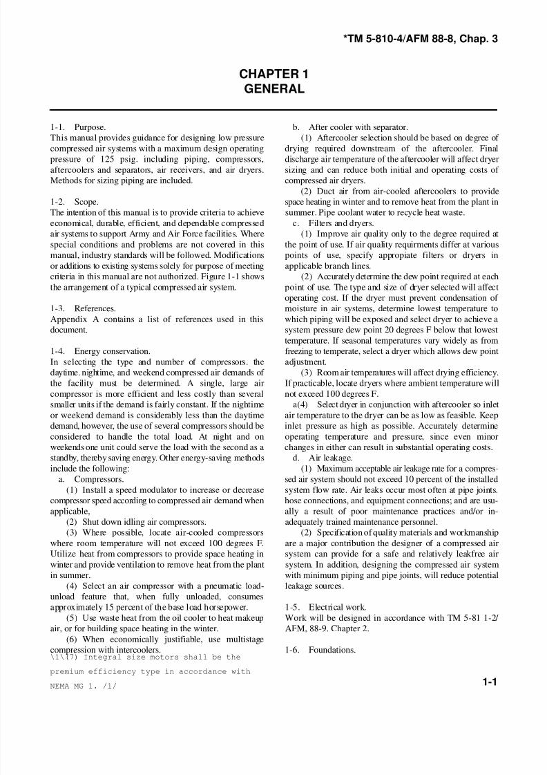
CHAPTER 1GENERAL
1-1. Purpose. b. After cooler with separator.
This manual provides guidance for designing low pressure (1) Aftercooler selection should be based on degree of compressed air systems with a maximum design operating drying required downstream of the aftercooler. Final
pressure of 125 psig. including piping, compressors, discharge air temperature of the aftercooler will affect dryer
aftercoolers and separators, air receivers, and air dryers. sizing and can reduce both initial and operating costs of
Methods for sizing piping are included. compressed air dryers.
1-2. Scope. space heating in winter and to remove heat from the plant in
The intention of this manual is to provide criteria to achieve summer. Pipe coolant water to recycle heat waste.
economical, durable, efficient, and dependable compressed c. Filters and dryers.
air systems to support Army and Air Force facilities. Where (1) Improve air quality only to the degree required at
special conditions and problems are not covered in this the point of use. If air quality requirments differ at various
manual, industry standards will be followed. Modifications points of use, specify appropiate filters or dryers in
or additions to existing systems solely for purpose of meeting applicable branch lines.
criteria in this manual are not authorized. Figure 1-1 shows (2) Accurately determine the dew point required at each
the arrangement of a typical compressed air system. point of use. The type and size of dryer selected will affect
1-3. References. moisture in air systems, determine lowest temperature to
Appendix A contains a list of references used in this which piping will be exposed and select dryer to achieve a
document. system pressure dew point 20 degrees F below that lowest
1-4. Energy conservation. freezing to temperate, select a dryer which allows dew point
In selecting the type and number of compressors. the adjustment.
daytime. nightime, and weekend compressed air demands of (3) Room air temperatures will affect drying efficiency.
the facility must be determined. A single, large air If practicable, locate dryers where ambient temperature will
compressor is more efficient and less costly than several not exceed 100 degrees F.
smaller units if the demand is fairly constant. If the nightime a(4) Select dryer in conjunction with aftercooler so inletor weekend demand is considerably less than the daytime air temperature to the dryer can be as low as feasible. Keep
demand, however, the use of several compressors should be inlet pressure as high as possible. Accurately determine
considered to handle the total load. At night and on operating temperature and pressure, since even minor
weekends one unit could serve the load with the second as a changes in either can result in substantial operating costs.
standby, thereby saving energy. Other energy-saving methods d. Air leakage.
include the following: (1) Maximum acceptable air leakage rate for a compres-
a. Compressors. sed air system should not exceed 10 percent of the installed
(1) Install a speed modulator to increase or decrease system flow rate. Air leaks occur most often at pipe joints.
compressor speed according to compressed air demand when hose connections, and equipment connections; and are usu-
applicable, ally a result of poor maintenance practices and/or in-
(2) Shut down idling air compressors. adequately trained maintenance personnel.
(3) Where possible, locate air-cooled compressors (2) Specification of quality materials and workmanship
where room temperature will not exceed 100 degrees F. are a major contribution the designer of a compressed airUtilize heat from compressors to provide space heating in system can provide for a safe and relatively leakfree air
winter and provide ventilation to remove heat from the plant system. In addition, designing the compressed air system
in summer. with minimum piping and pipe joints, will reduce potential
(4) Select an air compressor with a pneumatic load- leakage sources.
unload feature that, when fully unloaded, consumes
approximately 15 percent of the base load horsepower. 1-5. Electrical work.
(5) Use waste heat from the oil cooler to heat makeup Work will be designed in accordance with TM 5-81 1-2/
air, or for building space heating in the winter. AFM, 88-9. Chapter 2.
(6) When economically justifiable, use multistage
compression with intercoolers. 1-6. Foundations.
(2) Duct air from air-cooled aftercoolers to provide
operating cost. If the dryer must prevent condensation of
temperature. If seasonal temperatures vary widely as from
\1\(7) Integral size motors shall be the
premium efficiency type in accordance with
NEMA MG 1. /1/

8/4/2019 Unified Facilities Criteria (Ufc) for Compressed Air
http://slidepdf.com/reader/full/unified-facilities-criteria-ufc-for-compressed-air 9/23
*TM 5-810-4/AFM 88-8, Chap. 3
1-2
8/4/2019 Unified Facilities Criteria (Ufc) for Compressed Air
http://slidepdf.com/reader/full/unified-facilities-criteria-ufc-for-compressed-air 10/23
*TM 5-810-4/AFM 88-8, Chap. 3
1-3
a. A properly designed and constructed compressor should be consulted for seismic considerations.
foundation performs the following functions:
(1) Maintains the compressor in alignment and at
proper elevation.
(2) Minimizes vibration and prevents its transmission
to the building structure.
(3) Provides enough mass to support the compressor*s
weight plus disturbing forces.(4) Provides for the installation of sufficiently long
foundation bolts to insure good anchorage.
b. Concrete foundations must provide a permanently
rigid support for the machinery. Where the foundation is
exposed to freezing temperatures. its depth should extend
below the frost line. Isolating the foundation from any
building footings. walls, or floors will help to prevent
vibration from being carried into the building structure. TM
5-805-4/AFM 88-37 should be consulted for the
recommended vibration isolation practices. Each machine
requires an independent foundation. Operating platforms
must be isolated from the machinery foundations. Drawings
will be prepared for compressor foundations, and all
conditions surrounding the foundation will be made uniform.
The foundation should rest entirely on natural rock or
entirely on solid earth, but never on a combination of both.
If the foundation substructure rests on bedrock, a vibration
damping material should be interposed between the
substructure and the bedrock. If a foundation or foundation
substructure rests on piling, the piling should be covered
with a heavy, continuous, concrete mat. Foundation anchor
bolts hold the compressor down firmly and prevent it from
sliding laterally.
c. Horizontal and vertical reciprocating air compressors
will have a spring-mounted concrete inertia base installed ona concrete foundation block. Limit stops will be provided for
seismic considerations. For compressor sizes 25 horsepower
and larger, it becomes necessary to engage the services of a
foundation specialist to:
(1) Test the ability of the soil to carry the load.
(2) Consider the elastic characteristics of the ground on
which the foundation rests, since reciprocating machines
exert a dynamic loading as well as a static loading on the
foundation. The unbalanced forces of the compressor are
available from the manufacturer.
(3) Check wet season and dry season soil characteristics
(static loading limits and elasticity).
(4) Determine need for piling, either vertical or batter
piles (piles driven at an angle at the foundation ends).
d. Rotary machines have considerably less vibration, and
may have a spring-mounted structural steel base supported
on a concrete foundation block, with limit stops provided for
seismic considerations. Some rotary package compressors
may be mounted on existing concrete floors, depending on
size and manufacturer*s recommendations, requiring only lag
bolts to keep the machine in place.
e. Chapter 10, Seismic Design for Mechanical and
Electrical Elements. of TM 5-809-l0/AFM 88-3. Chapter 13
8/4/2019 Unified Facilities Criteria (Ufc) for Compressed Air
http://slidepdf.com/reader/full/unified-facilities-criteria-ufc-for-compressed-air 11/23
*TM 5-810-4/AFM 88-8, Chap. 3
2-1
CHAPTER 2AIR INTAKE
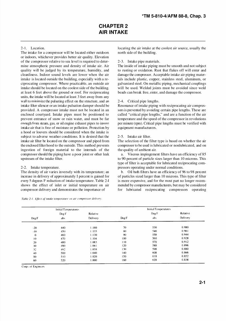
2-1. Location. locating the air intake at the coolest air source, usually the
The intake for a compressor will be located either outdoors north side of the building.
or indoors, whichever provides better air quality. Elevationof the compressor relative to sea level is required to deter- 2-3. Intake pipe materials.
mine atmospheric pressure and density of intake air. Air The inside of intake piping must be smooth and not subject
quality will be judged by its temperature, humidity, and to rusting or oxidation. Rust that flakes off will enter and
cleanliness. Indoor sound levels are lower when the air damage the compressor. Acceptable intake air piping mater-
intake is located outside the building, especially with a re- ials include plastic, copper, stainless steel, aluminum, or
ciprocating compressor. Where practicable, an outside air galvanized steel. On metallic piping, mechanical couplings
intake should be located on the coolest side of the building. will be used. Welded joints must be avoided since weld
at least 6 feet above the ground or roof. For reciprocating beads can break free, enter, and damage the compressor.
units, the intake will be located at least 3 feet away from any
wall to minimize the pulsating effect on the structure, and an 2-4. Critical pipe lengths.
intake filter silencer or an intake pulsation damper should be Resonance of intake piping with reciprocating air compres-
provided. A compressor intake must not be located in an sors is prevented by avoiding certain pipe lengths. These are
enclosed courtyard. Intake pipes must be positioned to called “critical pipe lengths,” and are a function of the air
prevent entrance of snow or rain water, and must be far temperature and the speed of the compressor in revolutions
enough from steam, gas, or oil engine exhaust pipes to insure per minute (rpm). Critical pipe lengths must be verified with
intake air that is free of moisture or pollution. Protection by equipment manufacturers.
a hood or louvers should be considered when the intake is
subject to adverse weather conditions. It is desired that the 2-5. Intake air filter.
intake air filter be located on the compressor and piped from The selection of the filter type is based on whether the air
the enclosed filter hood to the outside. This method prevents compressor to be used is lubricated or nonlubricated, and on
ingestion of foreign material to the internals of the the quality of ambient air.
compressor should the piping have a poor joint or other leak a. Viscous impingement filters have an efficiency of 85
upstream of the intake filter. to 90 percent of particle sizes larger than 10 microns. This
2-2. Intake temperature. pressors operating under normal conditions.The density of air varies inversely with its temperature; an b. Oil bath filters have an efficiency of 96 to 98 percent
increase in delivery of approximately I percent is gained for of particles sized larger than 10 microns. This type of filter
every 5 degrees F reduction of intake temperature. Table 2-I is more expensive, and for the most part no longer recom-
shows the effect of inlet or initial temperature on air mended by compressor manufacturers, but may be considered
compressor delivery and demonstrates the importance of for lubricated reciprocating compressors operating
type of filter is acceptable for lubricated reciprocating com-

8/4/2019 Unified Facilities Criteria (Ufc) for Compressed Air
http://slidepdf.com/reader/full/unified-facilities-criteria-ufc-for-compressed-air 12/23
*TM 5-810-4/AFM 88-8, Chap. 3
2-2
under heavy dust conditions.
c. Dry filters have an efficiency of 99 percent of particles
larger than 10 microns. Because of their high filtration effi-
ciency, these filters are the best selection for rotary and
reciprocating compressors. They must be used for nonlubri-
cated compressors and whenever air must be kept oil-free.
d. Two-stage dry filters, to provide 99 percent efficiencyof particles larger than 0.3 micron. will be used for cen-
trifugal units
e. With all types of filters, a means of monitoring the air
pressure drop through the element must be provided. which
indicates element contamination.
2-6. Dust and vapors.
All air compressors are sensitive to dust and airborne vapors
which can form adhesive, abrasive, and corrosive mixtures
within the compressor. These contaminants build up in rotat-
ing parts and can induce excessive wear and mechanical
unbalance, thereby damaging the compressor.
8/4/2019 Unified Facilities Criteria (Ufc) for Compressed Air
http://slidepdf.com/reader/full/unified-facilities-criteria-ufc-for-compressed-air 13/23
*TM 5-810-4/AFM 88-8, Chap. 3
3-1
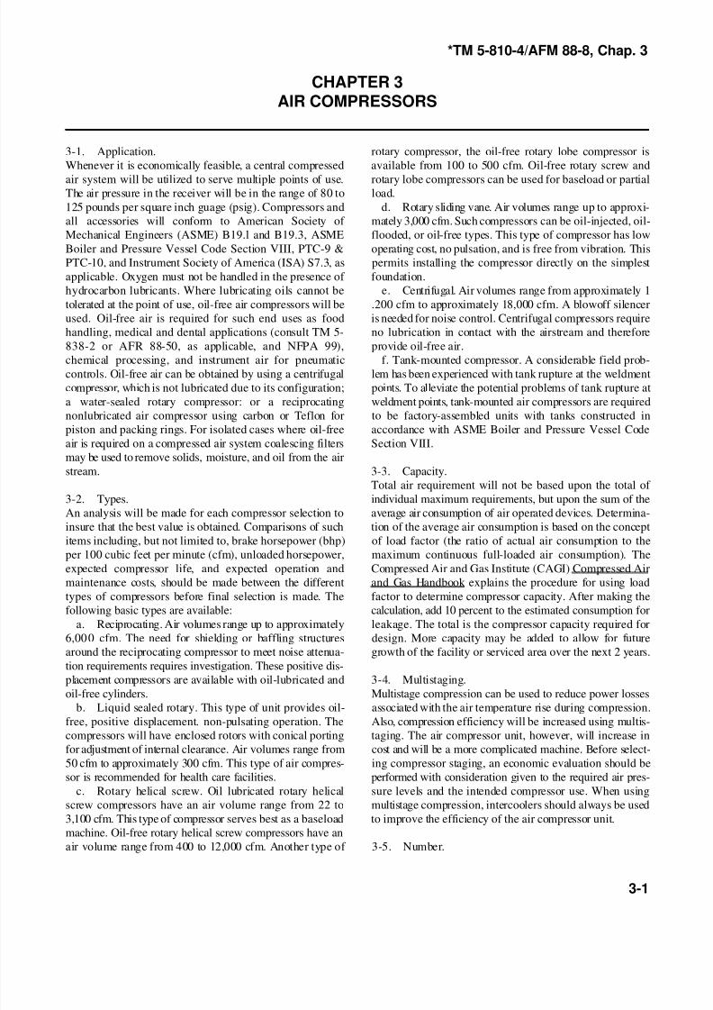
CHAPTER 3AIR COMPRESSORS
3-1. Application. rotary compressor, the oil-free rotary lobe compressor is
Whenever it is economically feasible, a central compressed available from 100 to 500 cfm. Oil-free rotary screw and
air system will be utilized to serve multiple points of use. rotary lobe compressors can be used for baseload or partialThe air pressure in the receiver will be in the range of 80 to load.
125 pounds per square inch guage (psig). Compressors and d. Rotary sliding vane. Air volumes range up to approxi-
all accessories will conform to American Society of mately 3,000 cfm. Such compressors can be oil-injected, oil-
Mechanical Engineers (ASME) B19.l and B19.3, ASME flooded, or oil-free types. This type of compressor has low
Boiler and Pressure Vessel Code Section VIII, PTC-9 & operating cost, no pulsation, and is free from vibration. This
PTC-10, and Instrument Society of America (ISA) S7.3, as permits installing the compressor directly on the simplest
applicable. Oxygen must not be handled in the presence of foundation.
hydrocarbon lubricants. Where lubricating oils cannot be e. Centrifugal. Air volumes range from approximately 1
tolerated at the point of use, oil-free air compressors will be .200 cfm to approximately 18,000 cfm. A blowoff silencer
used. Oil-free air is required for such end uses as food is needed for noise control. Centrifugal compressors require
handling, medical and dental applications (consult TM 5- no lubrication in contact with the airstream and therefore
838-2 or AFR 88-50, as applicable, and NFPA 99), provide oil-free air.
chemical processing, and instrument air for pneumatic f. Tank-mounted compressor. A considerable field prob-
controls. Oil-free air can be obtained by using a centrifugal lem has been experienced with tank rupture at the weldment
compressor, which is not lubricated due to its configuration; points. To alleviate the potential problems of tank rupture at
a water-sealed rotary compressor: or a reciprocating weldment points, tank-mounted air compressors are required
nonlubricated air compressor using carbon or Teflon for to be factory-assembled units with tanks constructed in
piston and packing rings. For isolated cases where oil-free accordance with ASME Boiler and Pressure Vessel Code
air is required on a compressed air system coalescing filters Section VIII.
may be used to remove solids, moisture, and oil from the air
stream. 3-3. Capacity.
3-2. Types. individual maximum requirements, but upon the sum of the
An analysis will be made for each compressor selection to average air consumption of air operated devices. Determina-
insure that the best value is obtained. Comparisons of such tion of the average air consumption is based on the conceptitems including, but not limited to, brake horsepower (bhp) of load factor (the ratio of actual air consumption to the
per 100 cubic feet per minute (cfm), unloaded horsepower, maximum continuous full-loaded air consumption). The
expected compressor life, and expected operation and Compressed Air and Gas Institute (CAGI) Compressed Air
maintenance costs, should be made between the different and Gas Handbook explains the procedure for using load
types of compressors before final selection is made. The factor to determine compressor capacity. After making the
following basic types are available: calculation, add 10 percent to the estimated consumption for
a. Reciprocating. Air volumes range up to approximately leakage. The total is the compressor capacity required for
6,000 cfm. The need for shielding or baffling structures design. More capacity may be added to allow for future
around the reciprocating compressor to meet noise attenua- growth of the facility or serviced area over the next 2 years.
tion requirements requires investigation. These positive dis-
placement compressors are available with oil-lubricated and 3-4. Multistaging.
oil-free cylinders. Multistage compression can be used to reduce power losses
b. Liquid sealed rotary. This type of unit provides oil- associated with the air temperature rise during compression.free, positive displacement. non-pulsating operation. The Also, compression efficiency will be increased using multis-
compressors will have enclosed rotors with conical porting taging. The air compressor unit, however, will increase in
for adjustment of internal clearance. Air volumes range from cost and will be a more complicated machine. Before select-
50 cfm to approximately 300 cfm. This type of air compres- ing compressor staging, an economic evaluation should be
sor is recommended for health care facilities. performed with consideration given to the required air pres-
c. Rotary helical screw. Oil lubricated rotary helical sure levels and the intended compressor use. When using
screw compressors have an air volume range from 22 to multistage compression, intercoolers should always be used
3,100 cfm. This type of compressor serves best as a baseload to improve the efficiency of the air compressor unit.
machine. Oil-free rotary helical screw compressors have an
air volume range from 400 to 12,000 cfm. Another type of 3-5. Number.
Total air requirement will not be based upon the total of

8/4/2019 Unified Facilities Criteria (Ufc) for Compressed Air
http://slidepdf.com/reader/full/unified-facilities-criteria-ufc-for-compressed-air 14/23
*TM 5-810-4/AFM 88-8, Chap. 3
3-2
An economic evaluation is necessary to determine whether a demands. In the automatic position. a time delay relay allows
central compressed air distribution system or a system of the compressor to operate for a predetermined length of time
separate compressors located near the point of usage is most unloaded, and then stops the unit. An air demand will again
cost-effective. Selection of the number of compressors for start the unit, when needed. For multiple compressor sys-
either situation should be based upon economics and other tems, the automatic start/stop sequence should alternate
factors such as system reliability. Seasonal or operational among all compressors.
load variations must also be considered. The efficiency of
larger compressors is generally higher than that of smaller 3-11. Sound tests.units, but use of smaller air-cooled units permits savings on After installation, a sound test must be performed on all
water, water piping, and system losses. Multiple units with compressors and accessories. Sound reading test results must
interconnecting piping give flexibility for maintenance shut- not exceed limitations set by OSHA Standard 1910.95. Mea-
down of one compressor. A smaller air compressor to handle surement of sound emitted from installed and operating air
requirements for weekends, holidays, and other low usage compressors will be in accordance with CAGI Compressed
times may also be economical. Air and Gas Handbook, Appendix B, “CAGI Pneurop Test
3-6. Location. ment.”
Compressors are to be located in clean, well lighted, and
ventilated areas of sufficient size to permit easy access for
cleaning, inspection, and any necessary dismantling, such as
removal of pistons, wheels, crankshafts, intercoolers, motors,
and drivers. Adequate aisle space is needed between items of equipment for normal maintenance as well as for equipment
removal and replacement.
3-7. Automatic warning and shutdown.
Air compressor systems will be protected against high tem-
perature, high pressure, low oil pressure, and in the case of
centrifugal compressors, excessive vibration. Protective
controls will include a fault indicator and a manual reset
device.
3-8. Vibration limits.
Compressor manufacturers should be contacted to obtain
guidance for establishing representative centrifugal com-
pressor vibration levels.
3-9. Lubrication system.
System design will be in accordance with the manufacturer*s
recommendations. Lubricant type will depend on the com-
pressor application:
a. Gravity, splash, or pressure petroleum oil will be used
where oil contamination of the compressed air at the point of
use is not a problem.
b. Synthetic liquid lubricants will be used where there is
a danger of fire, where the carbonaceous deposits must bereduced, or where lubricant is provided for extended mainte-
nance periods.
c. Solid lubricants, such as carbon or Teflon piston
rings, will be used for oil-free reciprocating compressed air
applications.
3-10. Control systems.
Energy can be conserved with a combination of pneumatic
cylinder unloading and a manual-off-automatic selector
switch on the compressor. When in the manual position, the
compressor loads and unloads to meet compressed air
Code for the Measurement of Sound from Pneumatic Equip-
8/4/2019 Unified Facilities Criteria (Ufc) for Compressed Air
http://slidepdf.com/reader/full/unified-facilities-criteria-ufc-for-compressed-air 15/23
*TM 5-810-4/AFM 88-8, Chap. 3
4-1
CHAPTER 4AIR DISCHARGE PIPE
4-1. Critical pipe lengths.
Consideration must be given to critical pipe lengths of the airdischarge pipe, and certain lengths must be avoided to
prevent resonance. The critical lengths vary with the type and
size of air compressor, and can be determined from air
compressor manufacturers.
4-2. Surge volume.
Consideration will also be given to surge volume between
reciprocating compressors and aftercoolersm to minimize
vibration and wear in the tubes and tube supports or baffles
in the aftercoolers. Pulsation dampers or surge bottles at the
compressor discharge will increase the installation cost,
however, they may reduce maintenance costs because at-
tenuation of discharge pulsations reduces wear and the po-
tential of tube failures.
4-3. Safety provision.
A safety valve must be provided between a positive displace-
ment compressor discharge and any block valve or other flow
restricting device, as well as between the compressor and an
internally finned tube after cooler. This is particularly true
with lubricated compressors. If deposits should clog the after
cooler, proper protection would be afforded. Safety valves
should be connected directly into the piping at the pressurepoint it is sensing, without unnecessary additional piping or
tubing. Safety valve discharge should be directed away from
personnel areas and traffic lanes.
8/4/2019 Unified Facilities Criteria (Ufc) for Compressed Air
http://slidepdf.com/reader/full/unified-facilities-criteria-ufc-for-compressed-air 16/23
*TM 5-810-4/AFM 88-8, Chap. 3
5-1
CHAPTER 5AFTERCOOLER AND SEPARATOR
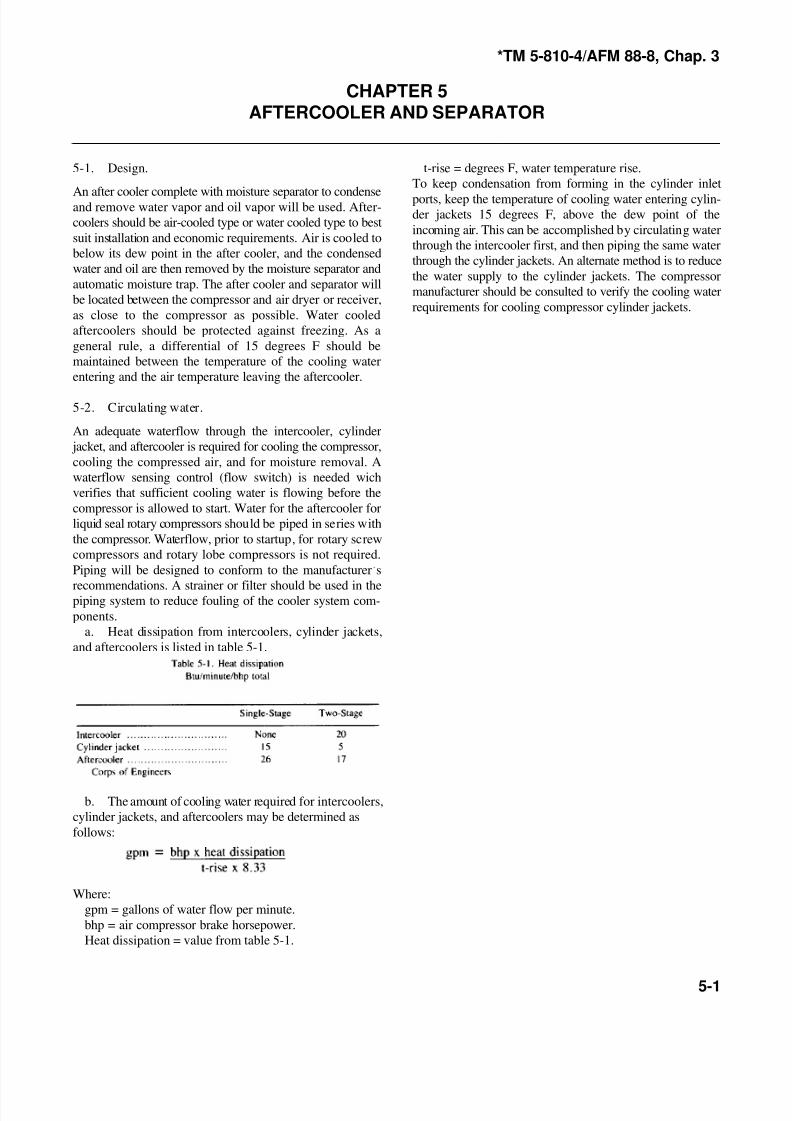
5-1. Design. t-rise = degrees F, water temperature rise.
To keep condensation from forming in the cylinder inlet
An after cooler complete with moisture separator to condenseand remove water vapor and oil vapor will be used. After-
coolers should be air-cooled type or water cooled type to best
suit installation and economic requirements. Air is cooled to
below its dew point in the after cooler, and the condensed
water and oil are then removed by the moisture separator and
automatic moisture trap. The after cooler and separator will
be located between the compressor and air dryer or receiver,
as close to the compressor as possible. Water cooled
aftercoolers should be protected against freezing. As a
general rule, a differential of 15 degrees F should be
maintained between the temperature of the cooling water
entering and the air temperature leaving the aftercooler.
5-2. Circulating water.
An adequate waterflow through the intercooler, cylinder
jacket, and aftercooler is required for cooling the compressor,
cooling the compressed air, and for moisture removal. A
waterflow sensing control (flow switch) is needed wich
verifies that sufficient cooling water is flowing before the
compressor is allowed to start. Water for the aftercooler for
liquid seal rotary compressors should be piped in series with
the compressor. Waterflow, prior to startup, for rotary screw
compressors and rotary lobe compressors is not required.
Piping will be designed to conform to the manufacturer*s
recommendations. A strainer or filter should be used in thepiping system to reduce fouling of the cooler system com-
ponents.
a. Heat dissipation from intercoolers, cylinder jackets,
and aftercoolers is listed in table 5-1.
b. The amount of cooling water required for intercoolers,
cylinder jackets, and aftercoolers may be determined as
follows:
Where:
gpm = gallons of water flow per minute.
bhp = air compressor brake horsepower.
Heat dissipation = value from table 5-1.
ports, keep the temperature of cooling water entering cylin-der jackets 15 degrees F, above the dew point of the
incoming air. This can be accomplished by circulating water
through the intercooler first, and then piping the same water
through the cylinder jackets. An alternate method is to reduce
the water supply to the cylinder jackets. The compressor
manufacturer should be consulted to verify the cooling water
requirements for cooling compressor cylinder jackets.

8/4/2019 Unified Facilities Criteria (Ufc) for Compressed Air
http://slidepdf.com/reader/full/unified-facilities-criteria-ufc-for-compressed-air 17/23
*TM 5-810-4/AFM 88-8, Chap. 3
6-1
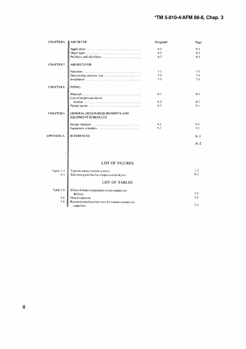
CHAPTER 6AIR DRYER
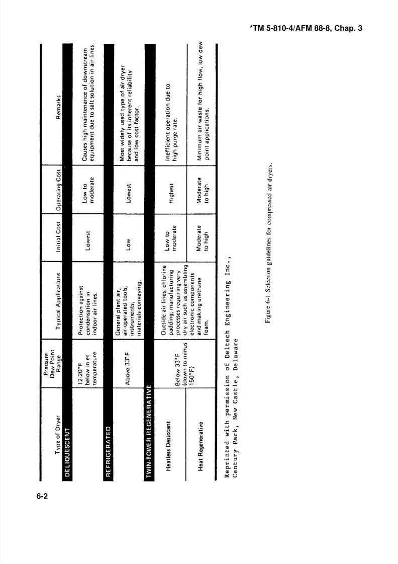
6-1. Application. purge air to regenerate the offstream tower. By reducing the
Some compressed air applications require moisture removal generative dryer operating costs are lower. High regenerativein addition to that provided by an aftercooler. Such applica- temperatures, however, are damaging to equipment and de-
tions include paint spraying, sandblasting, use of air-oper- siccant, so any savings in operating costs can be outweighed
ated tools and devices, pneumatic automatic temperature by the costs of maintenance and downtime.
controls, lines run outside in cold or subfreezing locations, c. Deliquescent. Deliquescent (salt pellet) dryers and
and lines passing through cold storage rooms. ethylene glycol stills are included in this manual for compari-
6-2. Dryer types. used because of their high operating cost and their limited
Supplementary moisture removal requires additional equip- salt or glycol into the airlines, resulting in corrosion and
ment, higher first cost, and higher operating cost for all potential damage to controls and tools. Glycol also reacts
drying methods. In determining overall costs, the initial pur- with certain constituents of the air (mainly carbon dioxide
chase price should be weighed against operating and mainte- and carbon monoxide) to form corrosive compounds that
nance costs. Figure 6-I illustrates the relative costs for the attack piping and equipment.
various types of dryers, and presents selection guidelines. In
determining the type of dryer to be used for a given 6.3. Prefilters and afterfilters.
application, drying requirements, flow, pressure, inlet tem-
peratures, and the pressure dew point must be accurately Consideration should be given to providing a prefilter up-
determined. The dryer that meets these requirements most stream of the air dryer and an afterfilter downstream of the
economically and efficiently should be selected. The various air dryer. A prefilter may be required to remove compressor
drying methods are as follows: carry-over oil and other undesirable particles from the air
a. Refrigeration. Refrigeration dryers remove moisture prior to the air entering the air dryer. This filter can extend
from compressed air by cooling the air in a heat exchanger. the life of the air dryer and reduce air dryer maintenance
This condenses and removes the moisture from the airstream costs. An afterfilter should be considered to protect the
and produces an operating pressure dew point at the dryer downstream piping system and equipment from impurities
outlet in the range of 35 to 39 degrees F. By adjusting the and undesirable particles added to the air as a result of refrigeration unit operating parameters, these units can pro- passing through the air dryer. Air dryer manufacturers should
duce pressure dew points of 50 degrees F. Higher dew points be consulted for recommendations and selection of prefilters
are available in either direct refrigeration or chiller-type and after filters for specific air quality requirements.
design.
b. Twin-tower regenerative. Regenerative dryers utilize
nonconsumable desiccants to remove moisture from com-
pressed air. Inlet air is automatically cycled between two
desiccant towers, one absorbing moisture from the inlet air
while the other is being regenerated. This method of regen-
eration includes the following dryer classifications:
(1) Heatless desiccant regeneration passes a quantity of
dried (purge) air through the offstream bed. No external heat
is applied. This type, with a field-adjustable purge controlshould be selected so that purge rate (and therefor pressure
dew point) can be adjusted to accomodate seasonal
variations in ambient temperatures, thereby reducing operat-
ing costs. Heatless dryers are capable of providing minus
150 degrees F, pressure dew point. Maintenance costs are
low since there are few* moving parts. With adequate prefil-
tering to remove oil, desiccant replacement requirements are
minimal.
(2) Heat regenerative dryers utilize heat from an
external source (either electric or steam) in conjunction with
amount of purge air required for regeneration, the heat re-
son and general information purposes only, and will not be
effect on pressure dew point. These types of dryers carry over
8/4/2019 Unified Facilities Criteria (Ufc) for Compressed Air
http://slidepdf.com/reader/full/unified-facilities-criteria-ufc-for-compressed-air 18/23
*TM 5-810-4/AFM 88-8, Chap. 3
6-2
8/4/2019 Unified Facilities Criteria (Ufc) for Compressed Air
http://slidepdf.com/reader/full/unified-facilities-criteria-ufc-for-compressed-air 19/23
*TM 5-810-4/AFM 88-8, Chap. 3
7-1
CHAPTER 7AIR RECEIVER
7-1. Functions.
The air receiver dampens pulsations entering the dischargeline from the compressor; serves as a reservoir for sudden or
unusually heavy demands in excess of compressor capacity;
prevents too frequent loading and unloading (short cycling)
of the compressor; and separates moisture and oil vapor,
allowing the moisture carried over from the aftercoolers to
precipitate. Air receivers shall be constructed in accordance
with ASME Boiler and Pressure Vessel Code Section VIII.
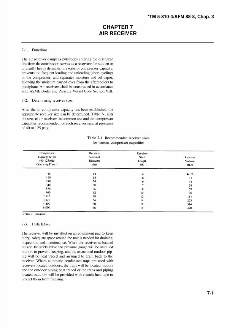
7-2. Determining receiver size.
After the air compressor capacity has been established, the
appropriate receiver size can be determined. Table 7-1 lists
the sizes of air receivers in common use and the compressor
capacities recommended for each receiver size, at pressures
of 40 to 125 psig.
7-3. Installation.
The receiver will be installed on an equipment pad to keepit dry. Adequate space around the unit is needed for draining,
inspection, and maintenance. When the receiver is located
outside, the safety valve and pressure gauge will be installed
indoors to prevent freezing, and the associated outdoor pip-
ing will be heat traced and arranged to drain back to the
receiver. Where automatic condensate traps are used with
receivers located outdoors, the traps will be located indoors
and the outdoor piping heat traced or the traps and piping
located outdoors will be provided with electric heat tape to
protect them from freezing.
8/4/2019 Unified Facilities Criteria (Ufc) for Compressed Air
http://slidepdf.com/reader/full/unified-facilities-criteria-ufc-for-compressed-air 20/23
*TM 5-810-4/AFM 88-8, Chap. 3
8-1
CHAPTER 8PIPING
8-1. Materials. pressor and after cooler or receiver, a safety valve or valves
a. Steel compressed air piping will be Schedule 80 for or valves will have a total capacity sufficient to handle thesizes 2 inches and smaller and Schedule 40 for sizes over 2 entire output of the compressor. (If no safety valve is used,
inches and will be galvanized or black steel or stainless steel. and the isolation valve is closed upon starting, or anytime
Copper compressed air piping or tubing will be Type K or during compressor operation, sufficient pressure may be built
Type L. Fiberglass reinforced plastic (FRP), as specified in up which could cause injury or damage.) A strainer or filter
Mil. Spec. MIL-P-28584, may also be used within the and a lubricator must be provided in piping that serves tools.
following limitations: Flexible connectors, such as flexible metal hose, will be used
(1) 150 psig maximum pressure, up to 200 degrees F. to connect the discharge piping system to the air
(2) 75 psig maximum pressure, up to 250 degrees F. compressors. Where air quality downstream of the
Pipe fittings will be galvanized or black steel or stainless compressor. receiver, and dryer is not assured for the end
steel, to match piping used. When copper pipe or tubing is use, the required additional filtration will be provided at the
used, brazed joints will he used for connections. Brazing point of use.
filler metals with melting temperatures between 1 ,000 de-
grees F and 1 ,600 degrees F will be used. Soldered joints
should not be used.
b. Thermoplastic piping systems for transport or storage
of compressed air will not be allowed. Safety records show
that leaks in these types of pipe (when used for compressed
air service) have caused the pipe to rupture, causing serious
injury to personnel and/or property damage.
8-2. Loss of air pressure due to friction.
The loss of pressure in piping is caused by resistance in pipe,
fittings, and valves, which dissipates energy by producing
turbulence. The piping system will be designed for amaximum allowable pressure drop of 5 percent from the
compressor to the most distant point of use. The Darcy
formula and nomograph shown in the Crane Co. Technical
Paper No. 410 may be used to determine pressure drop
through pipe, valves, and fittings.
8-3. Piping layout.
Where possible the piping system should be arranged as a
closed loop or “ring main” to allow for more uniform air
distribution to consumption points and to equalize pressure
in the piping. Separate services requiring heavy air consump-
tion and at long distances from the compressor unit shouldbe supplied by separate main airlines. Pipis to be installed
parallel with the lines of the building, with main and branch
headers sloping down toward a dead end. Traps will be
installed in airlines at all low points and dead ends to remove
condensed moisture. Automatic moisture traps used for this
purpose are effective only when the air has been cooled and
the moisture has precipitated. Branch headers from compres-
sed air mains will be taken off at the top to avoid picking up
moisture. When an isolation valve, or other flow restricting
device, is placed in the discharge line between the com-
will be placed in the pipeline between them. The safety valve

8/4/2019 Unified Facilities Criteria (Ufc) for Compressed Air
http://slidepdf.com/reader/full/unified-facilities-criteria-ufc-for-compressed-air 21/23
*TM 5-810-4/AFM 88-8, Chap. 3
9-1
CHAPTER 9GENERAL DESIGN AND EQUIPMENT SCHEDULES
9-1. Design analysis. d. Air dryer.
The following items will be considered in the design (2) Capacity (cfm and operating pressure).analysis: (3) Dew point temperature entering and leaving.
a. Application (hospital. industrial. etc.). (4) Ambient temperature (degrees F).
b. Maximum operating pressure required. (5) Volts, phase. hertz (if applicable).
c. Location of air requirements in buildings. (6) Accessory list.
d. Air usage. continuous or intermittent demand. (7) Spare parts list.
e. Operating pressure dew point requirements.
f. Air filtration needs at points of use.
g. Need for oil-free air.
9-2. Equipment schedules.
Equipment schedules will be shown on the drawings. includ-
ing the following:a. Air compressor.
(1) Capacity (cubic feet of free air per minute).
(2) Discharge pressure. psig.
(3) Minimum motor horsepower.
(4) Volts, phase, hertz.
(5) Accessory list.
(6) Spare parts list.
b. Air receiver.
(1) Capacity (cubic feet of volume).
(2) Design pressure, psig.
(3) Type horizontal (vertical).
(4) Diameter (feet).
(5) Length (feet).(6) Accessory list.
(7) Spare parts list.
c. After cooler-separator.
(1) Water cooled.
(a) Capacity (cfm and psig).
(b) Dew point temperature entering and leaving.
(c) Length (inches). diameter (inches).
(d) Cooling water.
— Gpm flow.
— Temperature in.
— Temperature out.
(e) Accessory list.
(f) Spare parts list.
(2) Air cooled.
(a) Capacity (cfm and psig).
(b) Compressed air inlet temperature entering after-
cooler.
(c) Approach temperature.
(d) Ambient air temperature.
(e) Minimum fan motor horsepower.
(f) Volts, phase, hertz.
(g) Accessory list.
(h) Spare parts list.
(1) Type.

8/4/2019 Unified Facilities Criteria (Ufc) for Compressed Air
http://slidepdf.com/reader/full/unified-facilities-criteria-ufc-for-compressed-air 22/23
*TM 5-810-4/AFM 88-8, Chap. 3
A-1
APPENDIX AREFERENCES
Government Publications.
Departments of the Army Air Force, and Navy.
AFR 88-50 Criteria for Design and Construction
of Air Force Health Facilities
TM 5-805-4/AFM 88-37 Noise and Vibration Control for
Mechanical Equipment.
TM 5-809-10/AFM 88-3. Seismic Design for Buildings.
Chap. 13
TM 5-81 1-2/AFM5 Electrical Design: Interior Electrical
88-9. Chap.2 System.
TM 5-838-2 Army Health Facility Design.
Military Specification (Mil. Spec.)
MIL-P-28584A Pipe and Pipe Fittings, Glass
Fiber Reinforced Plastic, forCondensate Return Lines.
Occupational Safety and Health Administration (OSHA).
Bureau of National Affairs Inc., Washington, DC 20037
1910.95 Occupational Noise Exposure
Nongovernment Publications
American Society of Mechanical Engineers (ASME).
22 Law Drive. Box 2350. Fairfield, NJ. 07007-2350
B19.1-1985 Safety Standard for Air Compressor
& B19.1a-1985 Systems
B19.3-1986 Safety Standard for Compressors for
Process IndustriesBoiler and Pressure Vessel Code and Interpretation: Pressure Vessels. Division 1 (1986;
Section VIII Addenda:
Dec 1986; Dec 1987)
PTC 9-1970(R 1985) Displacement Compressors, Vacuum
with 1972 Errata) Pumps and Blowers
PTC 10-1965(R 1986) Compressors and Exhausters
Compressed Air and Gas Institute (CAGI). 1230 Keith
Building. 1621 Euclid Avenue, Cleveland, OH 44155
Compressed Air and Gas Handbook, 4th Ed., 1973
Crane Company. 300 Park Avenue. New York, NY 10022
Technical Paper No. Flow of Fluids Through Valves,410 Fittings and Pipe (Updated 1982)
Instrument Society of America (ISA). P.O. Box 3561.
Durham. NC 27702
8/4/2019 Unified Facilities Criteria (Ufc) for Compressed Air
http://slidepdf.com/reader/full/unified-facilities-criteria-ufc-for-compressed-air 23/23
*TM 5-810-4/AFM 88-8, Chap. 3
S7.3-1975(R 1981) Quality Standard for Instrument
Air
National Fire Protection Agency (NFPA), Batterymarch Park.
Quincy, MA 02269
99-1987 Standard for Health Care
Facilities