Embed Size (px)
Citation preview

UFC 3-220-01A 16 January 2004
UNIFIED FACILITIES CRITERIA (UFC)
DEEP FOUNDATIONS
APPROVED FOR PUBLIC RELEASE; DISTRIBUTION UNLIMITED

UFC 3-220-01A 16 January 2004
1
UNIFIED FACILITIES CRITERIA (UFC)
DEEP FOUNDATIONS
Any copyrighted material included in this UFC is identified at its point of use. Use of the copyrighted material apart from this UFC must have the permission of the copyright holder. U.S. ARMY CORPS OF ENGINEERS (Preparing Activity) NAVAL FACILITIES ENGINEERING COMMAND AIR FORCE CIVIL ENGINEER SUPPORT AGENCY Record of Changes (changes are indicated by \1\ ... /1/) Change No. Date Location
This UFC supersedes TI 818-02, dated 3 August 1998. The format of this UFC does not conform to UFC 1-300-01; however, the format will be adjusted to conform at the next revision. The body of this UFC is the previous TI 818-02, dated 3 August 1998.

UFC 3-220-01A 16 January 2004
2
FOREWORD \1\ The Unified Facilities Criteria (UFC) system is prescribed by MIL-STD 3007 and provides planning, design, construction, sustainment, restoration, and modernization criteria, and applies to the Military Departments, the Defense Agencies, and the DoD Field Activities in accordance with USD(AT&L) Memorandum dated 29 May 2002. UFC will be used for all DoD projects and work for other customers where appropriate. All construction outside of the United States is also governed by Status of forces Agreements (SOFA), Host Nation Funded Construction Agreements (HNFA), and in some instances, Bilateral Infrastructure Agreements (BIA.) Therefore, the acquisition team must ensure compliance with the more stringent of the UFC, the SOFA, the HNFA, and the BIA, as applicable. UFC are living documents and will be periodically reviewed, updated, and made available to users as part of the Services’ responsibility for providing technical criteria for military construction. Headquarters, U.S. Army Corps of Engineers (HQUSACE), Naval Facilities Engineering Command (NAVFAC), and Air Force Civil Engineer Support Agency (AFCESA) are responsible for administration of the UFC system. Defense agencies should contact the preparing service for document interpretation and improvements. Technical content of UFC is the responsibility of the cognizant DoD working group. Recommended changes with supporting rationale should be sent to the respective service proponent office by the following electronic form: Criteria Change Request (CCR). The form is also accessible from the Internet sites listed below. UFC are effective upon issuance and are distributed only in electronic media from the following source: • Whole Building Design Guide web site http://dod.wbdg.org/. Hard copies of UFC printed from electronic media should be checked against the current electronic version prior to use to ensure that they are current. AUTHORIZED BY: ______________________________________ DONALD L. BASHAM, P.E. Chief, Engineering and Construction U.S. Army Corps of Engineers
______________________________________DR. JAMES W WRIGHT, P.E. Chief Engineer Naval Facilities Engineering Command
______________________________________ KATHLEEN I. FERGUSON, P.E. The Deputy Civil Engineer DCS/Installations & Logistics Department of the Air Force
______________________________________Dr. GET W. MOY, P.E. Director, Installations Requirements and Management Office of the Deputy Under Secretary of Defense (Installations and Environment)

TI 818-023 August 1998
Technical Instructions
Design of Deep Foundations
HeadquartersU.S. Army Corps of EngineersEngineering DivisionDirectorate of Military ProgramsWashington, DC 20314-1000

CEMP-E TI 818-023 August 1998
TECHNICAL INSTRUCTIONS
Design of Deep Foundations
Any copyrighted material included in this document is identified at its point of use.Use of the copyrighted material apart from this document must have the permission of the copyright holder.
Approved for public release; distribution is unlimited.
Record of Changes (changes indicated by \1\..../1/)No. Date Location
This Technical Instruction supersedes EI 02C097, dated 1 July 1997.(EI 02C097 text is included in this Technical Instruction and may carry EI 02C097 identification.)

CEMP-E TI 818-023 August 1998
FOREWORD
These technical instructions (TI) provide design and construction criteria and apply toall U.S. Army Corps of Engineers (USACE) commands having military constructionresponsibilities. TI will be used for all Army projects and for projects executed for othermilitary services or work for other customers where appropriate.
TI are living documents and will be periodically reviewed, updated, and made availableto users as part of the HQUSACE responsibility for technical criteria and policy for newmilitary construction. CEMP-ET is responsible for administration of the TI system;technical content of TI is the responsibility of the HQUSACE element of the disciplineinvolved. Recommended changes to TI, with rationale for the changes, should be sentto HQUSACE, ATTN: CEMP-ET, 20 Massachusetts Ave., NW, Washington, DC20314-1000.
TI are effective upon issuance. TI are distributed only in electronic media through theTECHINFO Internet site http://www.hnd.usace.army.mil/techinfo/index.htm and theConstruction Criteria Base (CCB) system maintained by the National Institute ofBuilding Sciences at Internet site http://www.nibs.org/ccb/. Hard copies of theseinstructions produced by the user from the electronic media should be checked againstthe current electronic version prior to use to assure that the latest instructions are used.
FOR THE DIRECTOR OF MILITARY PROGRAMS:
KISUK CHEUNG, P.E.Chief, Engineering and Construction DivisionDirectorate of Military Programs

i
DEPARTMENT OF THE ARMY EI 02C097U.S. Army Corps of Engineers
CEMP-E Washington, DC 20314-1000
Engineering Instructions 01 July 1997No. 02C097
DESIGN OF DEEP FOUNDATIONS
Table of Contents(Click on chapter titles to view topics.)
Subject Paragraph Page Subject Paragraph Page
Chapter 1 Chapter 5Introduction Pile GroupsPurpose . . . . . . . . . . . . . . . . . . . . . . . . . . . . 1 1-1Applicability . . . . . . . . . . . . . . . . . . . . . . . . 2 1-1Scope . . . . . . . . . . . . . . . . . . . . . . . . . . . . . . 3 1-1References . . . . . . . . . . . . . . . . . . . . . . . . . . 4 1-1General Design Methodology . . . . . . . . . 5 1-1Types of Deep Foundations . . . . . . . . . . . 6 1-4Selection of Deep Foundations . . . . . . . . . 7 1-7Site and Soil Investigations . . . . . . . . . . . 8 1-12
Chapter 2Design StressesConstraints . . . . . . . . . . . . . . . . . . . . . . . . . 1 2-1Factored Loads . . . . . . . . . . . . . . . . . . . . . 2 2-1Structural Design of Driven Piles . . . . . . 3 2-4Structural Design of Drilled Shafts . . . . . 4 2-12
Chapter 3Vertical LoadsDesign Philosophy . . . . . . . . . . . . . . . . . . . 1 3-1Driven Piles . . . . . . . . . . . . . . . . . . . . . . . . 2 3-6Drilled Shafts . . . . . . . . . . . . . . . . . . . . . . . 3 3-20
Chapter 4Lateral LoadsDescription of the Problem . . . . . . . . . . . . 1 4-1Nonlinear Pile and p-y Model for Soil . . . . . . . . . . . . . . . . . . . . . . . . . . . . . . . 2 4-1Development of p-y Curve for Soils . . . . . . . . . . . . . . . . . . . . . . . . . . . . . . 3 4-4Analytical Method . . . . . . . . . . . . . . . . . . . 4 4-16Status of the Technology . . . . . . . . . . . . . 5 4-36
Design Considerations . . . . . . . . . . . . . . . 1 5-1Factors Influencing Pile Group Behavior . . . . . . . . . . . . . . . . . . . . . . . . . . 2 5-1Design for Vertical Loads . . . . . . . . . . . . . 3 5-3Design for Lateral Loads . . . . . . . . . . . . . 4 5-9Computer Assisted Analysis . . . . . . . . . . 5 5-19
Chapter 6Verification of DesignFoundation Quality . . . . . . . . . . . . . . . . . . 1 6-1Driven Piles . . . . . . . . . . . . . . . . . . . . . . . . 2 6-1Drilled Shafts . . . . . . . . . . . . . . . . . . . . . . . 3 6-6Load Tests . . . . . . . . . . . . . . . . . . . . . . . . . 4 6-11
Appendix AReferences and Bibliography . . . . . . . . . A-1 A-1
Appendix BPipe Piles . . . . . . . . . . . . . . . . . . . . . . . . . B-1 B-1
Appendix CComputer Program AXILTR . . . . . . . . . . C-1 C-1
Appendix DModification of p-y curves for Battered Piles . . . . . . . . . . . . . . . . . . . . D-1 D-1

Ac As
EI 02C09701 Jul 97
ii
List of Figures
Figure Page Figure Page
1-1. Timber pile splice and boot . . . . . . . . . . . . . . . 1-51-2. Concrete pile splice and boot . . . . . . . . . . . . . . 1-61-3. Steel pile splices . . . . . . . . . . . . . . . . . . . . . . . . 1-61-4. Drilled shaft details . . . . . . . . . . . . . . . . . . . . . . 1-91-5. Axial-load deflection relationship . . . . . . . . 1-101-6. Driven pile applications . . . . . . . . . . . . . . . . 1-131-7. Load resistance of drilled shaft in
various soils . . . . . . . . . . . . . . . . . . . . . . . . 1-151-8. Variation of K for clay with respectcu
to undrained shear strength and over- consolidation ratio . . . . . . . . . . . . . . . . . . . . 1-20
2-1. Eccentric load on a pile group . . . . . . . . . . . . . 2-32-2. Limits to pile driving stresses . . . . . . . . . . . . . . 2-53-1. Loading support of deep foundations . . . . . . . . 3-23-2. Distribution of skin friction and the
associated load resistance . . . . . . . . . . . . . . . . 3-43-3. Critical depth ratio . . . . . . . . . . . . . . . . . . . . . . 3-53-4. Limiting base resistance for Meyerhof
and Nordlund methods . . . . . . . . . . . . . . . . . . 3-63-5. Illustration of input parameters for
equation 3-7a . . . . . . . . . . . . . . . . . . . . . . . . . 3-93-6. Variation of coefficient " and bearingf
capacity factor N with respect to Nr . . . . . 3-11q
3-7. Variation of the coefficient K with respect to Nr . . . . . . . . . . . . . . . . . . . . . . . . 3-12
3-8. Ratio */N for given displacement volume V . . . . . . . . . . . . . . . . . . . . . . . . . . . 3-13
3-9. Correction factor C with respectf
to */Nr . . . . . . . . . . . . . . . . . . . . . . . . . . . . . 3-143-10. Estimating pile tip capacity from CPT
data . . . . . . . . . . . . . . . . . . . . . . . . . . . . . . . 3-163-11. Lambda correlation factor for clay . . . . . . . . 3-173-12. Sleeve friction factor for clays . . . . . . . . . . . 3-183-13. Lateral earth pressure and friction angle
factor $ . . . . . . . . . . . . . . . . . . . . . . . . . . . . 3-18f
3-14. Sleeve friction factors for sands . . . . . . . . . . 3-193-15. Driven steel pipe pile . . . . . . . . . . . . . . . . . . 3-213-16. Settlement influence factor I . . . . . . . . . . . 3-29sock
3-17. Modulus reduction ratio E /E . . . . . . . . 3-29mass core
3-18. Elastic modulus of intact rock . . . . . . . . . . . . 3-313-19. Pullout force in underreamed drilled
shaft . . . . . . . . . . . . . . . . . . . . . . . . . . . . . . . 3-333-20. Deep foundation resisting uplift thrust . . . . . 3-343-21. Deep foundation resisting downdrag . . . . . . 3-353-22. Load-transfer curves used in AXILTR . . . . . 3-363-23. General load-transfer curves for clay . . . . . . 3-403-24. General load-transfer functions for sand . . . 3-41
4-1. Model of pile under lateral loading with p-y curves . . . . . . . . . . . . . . . . . . . . . . . 4-2
4-2. Distribution of unit stresses against a pile before and after lateral deflection . . . . . . . . . . . . . . . . . . . . . . . . . . . 4-3
4-3. Pipe pile and soil elements . . . . . . . . . . . . . . . 4-44-4. Conceptual p-y curve . . . . . . . . . . . . . . . . . . . 4-44-5. Wedge-type failure of surface soil . . . . . . . . . 4-54-6. Potential failure surfaces generated
by pipe at several diameters below ground surface . . . . . . . . . . . . . . . . . . . . . . . 4-6
4-7. Characteristics shape of the p-y curves for soft clay below the water table . . . . . . . . . . . . . . . . . . . . . . . . . . 4-6
4-8. Characteristic shape of p-y curve for static loading in stiff clay below the water table . . . . . . . . . . . . . . . . . . . . . . . . . . 4-9
4-9. Values of empirical parameters A and A . . 4-10s c
4-10. Characteristic shape of p-y curve for cyclic loading in stiff clay below the water table . . . . . . . . . . . . . . . . . . . . . . . . . 4-11
4-11. Characteristic shape of p-y curve for static loading in stiff clay above the water table . . . . . . . . . . . . . . . . . . . . . . . . . 4-12
4-12. Characteristic shape of p-y curve for cyclic loading in stiff clay above the water table . . . . . . . . . . . . . . . . . . . . . . . . . 4-13
4-13. Characteristic shape of a family of p-y curves for static and cyclic loading in sand . . . . . . . . . . . . . . . . . . . . . . . . . . . . . . . 4-14
4-14. Values of coefficients and . . . . . . . . . 4-164-15. Nondimensional coefficient B for soil
resistance versus depth . . . . . . . . . . . . . . . . 4-164-16. Form of variation of soil modulus
with depth . . . . . . . . . . . . . . . . . . . . . . . . . . 4-194-17. Pile deflection produced by lateral
load at mudline . . . . . . . . . . . . . . . . . . . . . . 4-214-18. Pile deflection produced by moment
applied at mudline . . . . . . . . . . . . . . . . . . . 4-224-19. Slope of pile caused by lateral load
at mudline . . . . . . . . . . . . . . . . . . . . . . . . . . 4-244-20. Slope of pile caused by moment
applied at mudline . . . . . . . . . . . . . . . . . . . 4-254-21. Bending moment produced by lateral
load at mudline . . . . . . . . . . . . . . . . . . . . . . 4-264-22. Bending moment produced by
moment applied at mudline . . . . . . . . . . . . 4-27

EI 02C09701 Jul 97
iii
List of Figures
Figure Page Figure Page
4-23. Shear produced by lateral load at 5-8. Axial load versus settlement for mudline . . . . . . . . . . . . . . . . . . . . . . . . . . . . 4-28
4-24. Shear produced by moment applied at 5-9. Pile loading-Case 4 . . . . . . . . . . . . . . . . . . . . 5-17 mudline . . . . . . . . . . . . . . . . . . . . . . . . . . . . 4-29
4-25. Deflection of pile fixed against rotation analyzed in example problem . . . . . . . . . . . . 5-20 at mudline . . . . . . . . . . . . . . . . . . . . . . . . . . 4-30
4-26. Soil-response curves . . . . . . . . . . . . . . . . . . . 4-324-27. Graphical solution for relative stiffness equipment . . . . . . . . . . . . . . . . . . . . . . . . . . . 6-5
factor . . . . . . . . . . . . . . . . . . . . . . . . . . . . . . 4-344-28. Comparison of deflection and bending analysis . . . . . . . . . . . . . . . . . . . . . . . . . . . . . 6-7
moment from nondimensional and computer solutions . . . . . . . . . . . . . . . . . . . 4-37
5-1. Groups of deep foundations . . . . . . . . . . . . . . . 5-25-2. Stress zones in soil supporting piles . . . . . . . . . 5-45-3. Typical pile-supported bent . . . . . . . . . . . . . 5-105-4. Simplified structure showing coordinate C-3. Plotted output for downdrag problem . . . . . . C-11
systems and sign conventions . . . . . . . . . . . 5-125-5. Set of pile resistance functions for a piles . . . . . . . . . . . . . . . . . . . . . . . . . . . . . . . D-2
given pile . . . . . . . . . . . . . . . . . . . . . . . . . . . 5-135-6. Sketch of a pile-supported retaining
wall . . . . . . . . . . . . . . . . . . . . . . . . . . . . . . . 5-145-7. Interaction diagram of reinforced
concrete pile . . . . . . . . . . . . . . . . . . . . . . . . 5-15
reinforced concrete pile . . . . . . . . . . . . . . . . 5-15
5-10. Plan and elevation of foundation
6-1. Schematic of wave equation model . . . . . . . . 6-36-2. Schematic of field pile driving analyzer
6-3. Example results of CAPWAPC
6-4. Typical Osterberg cell load test . . . . . . . . . . . 6-14C-1. Schematic diagram of soil and pile
elements . . . . . . . . . . . . . . . . . . . . . . . . . . . . C-5C-2. Plotted output for pullout and uplift
problems . . . . . . . . . . . . . . . . . . . . . . . . . . . . C-9
D-1. Modification of p-y curves for battered

EI 02C09701 Jul 97
iv
List of Tables
Table Page Table Page
1-1. General Design Methodology 4-4. Nondimensional Coefficients for p-y for Deep Foundations . . . . . . . . . . . . . . . . . . . 1-2
1-2. Types of Deep Foundations . . . . . . . . . . . . . . . 1-41-3. Standard H-piles: Dimensions and
Properties . . . . . . . . . . . . . . . . . . . . . . . . . . . . 1-81-4. Characteristics of Deep Foundations . . . . . . 1-11(This table is sized for 11" x 17" paper. It can be viewed on 5-1. Equivalent Mat Method of Group Pilescreen, but will not print completely on 8.5" x 11" paper.) Capacity Failure in Soft Clays . . . . . . . . . . 5-61-5. Drilled Shaft Applications . . . . . . . . . . . . . . 1-162-1. Tolerances in Drilled Shaft
Construction . . . . . . . . . . . . . . . . . . . . . . . . . . 2-22-2. Performance and Eccentricity Factors . . . . . . . 2-32-3. Allowable Stresses for Fully Supported
Piles . . . . . . . . . . . . . . . . . . . . . . . . . . . . . . . . . 2-62-4. Allowable Concrete Stresses, Prestressed
Concrete Piles . . . . . . . . . . . . . . . . . . . . . . . . . 2-72-5. Cast-in-Place and Mandrel-driven Piles,
Allowable Concrete Stresses . . . . . . . . . . . . . 2-82-6. Allowable Stresses for Pressure-treated
Round Timber Piles for Normal Loads in Hydraulic Structures . . . . . . . . . . . . . . . . . . 2-8
2-7. Minimum Requirements for Drilled Shaft Design . . . . . . . . . . . . . . . . . . . . . . . . . . 2-9
3-1. Vertical Load Analysis . . . . . . . . . . . . . . . . . . . 3-33-2. Factors of Safety for Bearing Capacity . . . . . . . 3-73-3. General Design Procedure of a Driven
Pile . . . . . . . . . . . . . . . . . . . . . . . . . . . . . . . . . 3-83-4. Q by the Nordlund Method . . . . . . . . . . . . . 3-15u
3-5. Adhesion Factors for Cohesive Soil . . . . . . . 3-183-6. Calculations of Vertical Loads in a
Single Pile . . . . . . . . . . . . . . . . . . . . . . . . . . 3-223-7. Design of a Drilled Shaft . . . . . . . . . . . . . . . 3-273-8. Adhesion Factors for Drilled Shafts in
Cohesive Soil . . . . . . . . . . . . . . . . . . . . . . . 3-283-9. Dimensionless Pressuremeter
Coefficient . . . . . . . . . . . . . . . . . . . . . . . . . . 3-303-10. Empirical Tip Coefficient C . . . . . . . . . . . . 3-38b
3-11. Application of Drilled Shaft Design . . . . . . . 3-424-1. Representative Values of g . . . . . . . . . . . . . . 4-550
4-2. Representative Values of k for Stiff Clays . . . . . . . . . . . . . . . . . . . . . . . . . . . . . . . . 4-7
4-3. Representative Values of g for Stiff50
Clays . . . . . . . . . . . . . . . . . . . . . . . . . . . . . . . . 4-8
Curves for Sand . . . . . . . . . . . . . . . . . . . . . 4-154-5. Representative Values of k (lb/cu in.)
for Sand . . . . . . . . . . . . . . . . . . . . . . . . . . . 4-174-6. Moment Coefficients at Top of Pile
for Fixed-Head Case . . . . . . . . . . . . . . . . . . 4-23
5-2. Equivalent Mat Method for Estimating Consolidation Settlement of PileGroups in Clay . . . . . . . . . . . . . . . . . . . . . . . 5-7
5-3. Values of Loading Employed in Analysis . . . . . . . . . . . . . . . . . . . . . . . . . . . 5-16
5-4. Computed Movements of Origin of Global Coordinate System . . . . . . . . . . . . . 5-16
5-5. Computed Movements and Loads at Pile Heads . . . . . . . . . . . . . . . . . . . . . . . . . . 5-18
6-1. Procedure for Verifying Design and Structural Integrity of Driven Piles . . . . . . 6-2
6-2. Recommended Soil Parameters for Wave Equation . . . . . . . . . . . . . . . . . . . . . . . . . . . 6-4
6-3. Specifications for Bentonite Slurry . . . . . . . 6-96-4. Methods of Estimating Ultimate Pile
Capacity from Load Test Data . . . . . . . . . . 6-15B-1. Dimensions and Properties for Design
of Pipe Piles . . . . . . . . . . . . . . . . . . . . . . . . B-2C-1. Input Data . . . . . . . . . . . . . . . . . . . . . . . . . . . C-1C-2. Description of Input Parameters . . . . . . . . . C-2C-3. Output Data . . . . . . . . . . . . . . . . . . . . . . . . . C-6C-4. Listing of Data Input for Expansive Soil,
File DATLTR.TXT . . . . . . . . . . . . . . . . . . C-10C-5. Listing of Output for Pullout and Uplift
Problem . . . . . . . . . . . . . . . . . . . . . . . . . . . C-13C-6. Listing of Data Input for Settling Soil . . . . . C-16C-7. Listing of Output for Downdrag
Problem . . . . . . . . . . . . . . . . . . . . . . . . . . . C-16

EI 02C09701 Jul 97
1-1
Chapter 1Introduction
1. Purpose
This publication presents data, principles, and methods foruse in planning, design, and construction of deep foundations.Deep foundations are literally braced (supported) columnelements transmitting structure loads down to the subgradesupporting medium.
2. Applicability
These instructions are applicable to all HQUSACE elementsand USACE comands.
3. Scope
General information with respect to the selection and designof deep foundations is addressed herein. Single and groups ofdriven piles and drilled shafts under axial and lateral staticloads are treated. Some example problems and the mostwidely accepted computer methods are introduced. Thispublication is not intended for hydraulic structures; however,it does provide the following:
a. Guidance is provided to assist the efficient planning,design, and quality verification of the deep foundation.
b. Guidance is not specifically provided for design of sheetpiles used as retaining walls to resist lateral forces or for thedesign of stone columns. Other foundation structures may bedesigned as discussed below:
(1) Shallow foundations will be designed using TM 5-818-1, “Soils and Geology; Procedures for Foundation Design ofBuildings and Other Structures (Except HydraulicStructures).”
(2) Refer to Foundations (Pile Buck Inc. 1992) and PileFoundations in Engineering Practice (Prakash and Sharma1989) for guidance on design of deep foundations subject todynamic load.
c. Guidance for construction of deep foundations isprovided only in minor detail. For construction of deepfoundations, the following references are offered:
(1) Some guidance for selection of pile drivingequipment and construction of driven piles is provided inTM 5-849-1, “Pile Driving Equipment.”
(2) Guidance for construction of drilled shafts isavailable in FHWA-HI-88-042, “Drilled Shafts:Construction Procedures and Design Methods” andAssociation of Drilled Shaft Contractors (ADSC)Publication, “Drilled Shaft Inspector's Manual.”
4. References
Appendix A contains a list of references used in thispublication.
5. General Design Methodology
A single drilled shaft or a group of driven piles is typicallydesigned to support a column load. The number of drivenpiles in a group is determined by dividing the column loadby the design load of a single pile. The piles should bearranged in the group to provide a spacing of about three tofour times the pile diameter B up to 6B. The diameter of thepiles may be increased to reduce the size of the pile cap ifappropriate. Table 1-1 describes a general designmethodology. Other design methodology aspects are thefollowing:
a. Load factor design. This publication applies loadfactors for design (LFD) of the structural capacity of deepfoundations. The sum of the factored loads shall not exceedthe structural resistance and the soil resistance. The LFD,the structural resistance, and the soil resistance are allrelated to the load factors as follows:
(1) Definition. The LFD may be defined as a conceptwhich recognizes that the different types i of loads Q that arei
applied to a structure have varied probabilities of occurence.Examples of types of loads applied to a structure include thelive load Q , dead load Q , wind load Q , and earthquakeLL DL WL
load Q . The probability of occurrence of each load isEL
accounted for by multiplying each Q by a load factor F >i i
1.0. The value of F depends on the uncertainty of the load.i
(2) Structural resistance. The sum of the factored loadsshall be less than the design strength


EI 02C09701 Jul 97
1-4
6. Types of Deep Foundations (Table 1-2). Large displacement and small displacement
Deep foundations are classified with respect to displacements ground, while nondisplacement piles are constructed in situas large displacement, small displacement, and and often are called drilled shafts. Augered cast concretenondisplacement, depending on the degree to which installation shafts are also identified as drilled shafts in this publication.disturbs the soil supporting the foundation
piles are fabricated prior to installation and driven into the
Table 1-2Types of Deep Foundations
a. Large displacement piles. Driven piles are classified bythe materials from which the pile is constructed, i.e., timber,concrete, or filled or unfilled steel pipe.

EI 02C09701 Jul 97
1-5
Figure 1-1. Timber pile splice and boot
(1) Timber piles. These are generally used forcomparatively light axial and lateral loads where foundationconditions indicate that piles will not be damaged by driving orexposed to marine borers. Overdriving is the greatest cause ofdamage to timber piles. Pile driving is often decided by ajudgment that depends on the pile, soil condition, and drivingequipment. Overdriving typically occurs when the dynamicstresses on the pile head exceed the ultimate strength of thepile. Timber piles can broom at the pile tip or head, split, orbreak when overdriven. Such piles have an indefinite lifewhen constantly submerged or where cut off below thegroundwater level. Some factors that might affect theperformance of timber piles are the following:
(a) Splicing of timber piles is expensive and time-consuming and should be avoided. The full bending resistanceof timber pile splices may be obtained by a concrete cover(Figure 1-1a) (Pile Buck Inc. 1992). Other transition splicersare available to connect timber with cast concrete or pipe piles.
(b) Tips of timber piles can be protected by a metal boot(Figure 1-1b).
(c) Timber piles are normally treated with creosote toprevent decay and environmental attack.
(d) American Society for Testing and Materials(ASTM) D 25 provides physical specifications of round timberpiles. Refer to Federal Specifications TT-W-00571J, “WoodPreservation: Treating Practices,” for other details.
(2) Precast concrete piles. These piles includeconventionally reinforced concrete piles and prestressedconcrete piles. Reinforced concrete piles are constructed withan internal reinforcement cage consisting of severallongitudinal bars and lateral ties, individual hoops, or a spiral.Prestressed concrete piles are constructed using steel rods or (b) Special steel points can be attached to precast precastwire strands under tension as reinforcement. Since the piles during casting of the piles and include steel H-pile tips orconcrete is under continuous compression, transverse cracks cast steel shoes (Figure 1-2).tend to remain closed; thus, prestressed piles are usually moredurable than conventionally reinforced piles. Influential (3) Raymond step-tapered piles. These consist of afactors for precast concrete piles include splices and steel corrugated steel shell driven into the ground using a mandrel.points. The shell consists of sections with variable diameters that
(a) Various splices are available to connect concrete rigid steel tube shaped to fit inside the shell. The mandrel ispiles. The splice will provide the tensile strength required withdrawn after the shell is driven and the shell filled withduring driving when the resistance to driving is low. Figure 1- concrete. Raymond step-tapered piles are predecessors of2a illustrates the cement-dowel splice. Refer to “Foundations” drilled shafts and are still popular in the southern United(Pile Buck Inc. 1992) for additional splices. States.
increase from the tip to the pile head. A mandrel is a heavy,
(4) Steel piles. These are generally H-piles and pipe piles.Pipe piles may be driven either “open-end” or “closed-end.”Steel piles are vulnerable to corrosion, particularly insaltwater; however, experience indicates they are not

EI 02C09701 Jul 97
1-6
Figure 1-2. Concrete pile splice and boot
Figure 1-3. Steel pile splices
significantly affected by corrosion in undisturbed soil. lists commonly available H-piles together with properties andSchematics of H-piles and pipe piles are presented in dimensions.Figure 1-3.
(a) Steel H-piles. This type can carry larger loads, bothaxially and in bending, than timber piles and can withstandrough handling. H-piles can be driven into dense soil, coarsegravel, and soft rock with minimum damage, and causeminimal displacement of the surrounding soil while beingdriven. Hardened and reinforced pile tips should be usedwhere large boulders, dense gravel, or hard debris may damagethe pile. Splices are commonly made with full penetration buttwelds or patented splicers (Figure 1-3a). H-piles can bendduring driving and drift from planned location. Thus, H-piles
may not be suitable when tolerance is small with respect tolocation and where absolute plumbness is required. Table 1-3
(b) Steel pipe piles. Commonly used steel pipe piles arelisted in Appendix B together with properties and dimensions.Steel pipe piles are generally filled with concrete after drivingto increase the structural capacity. If the soil inside the pipe isremoved during driving, open-end piles in cohesionless soilwill cause less soil displacement and compaction, and incohesive soils will cause less heaving of adjacent ground andnearby piles. If the soil inside the pipe is not removed duringdriving, the pipe becomes plugged and acts as a closed-enddisplacement pile. Criteria are presently unavailable forcomputing the depth at which a driven, open-end pile will plug.In cases where the foundation contains boulders, soft rock, or

EI 02C09701 Jul 97
1-7
other obstructions, the open-end pile permits inspection after (4) Pressure-grouted shafts. A special type ofremoval of the plug material and ensures that the load will be nondisplacement deep foundation is the uncased auger-placedtransferred directly to the load-bearing stratum. Splices are grout shaft. This shaft is constructed by advancing acommonly made by full penetration butt welds or fillet wells continuous-flight, hollow-stem auger to the required depth and(Figure 1-3b) or patented splicers. filling the hole bored by the concrete grout under pressure as
(5) Compaction piles. These are sometimes driven with installation, and shaft continuity should be verified by athe objective of increasing the density of loose, cohesionless combination of load tests and nondestructive testing assoils and reducing settlement. Piles with a heavy taper are described in Chapter 6.often most effective in deriving their support from friction.
b. Nondisplacement piles. This pile consists of a drilledshaft with a concrete cylinder cast into a borehole. Normally, Deep foundations provide an efficient foundation system forthe drilled shaft does not cause major displacement of the soils that do not have a shallow, stable bearing stratum.adjacent ground surface. The hole is usually bored with a short Selection of a deep foundation requires knowledge of itsflight or bucket auger. Loss of ground could occur if the characteristics and capacity.diameter of the hole is decreased because of inwarddisplacement of soft soil or if there is caving of soil from the a. Characteristics. Information adequate for reachinghole perimeter. Such unstable boreholes require stabilization preliminary conclusions about types of driven piles or drilledby the use of slurry or slurry and casing. Drilled shafts are not shafts to be selected for a project is given in Table 1-4. Thissubject to handling or driving stresses and therefore may be table lists major types of deep foundations with respect todesigned only for stresses under the applied service loads. capacity, application, relative dimensions, and advantages andNondisplacement may be categorized as follows: disadvantages. Refer to Foundations (Pile Buck Inc. 1992) for
(1) Uncased shafts. Figure 1-4 illustrates a typical general guidelines in the selection of a type of deep foundation.uncased drilled shaft with an enlarged base. The base is not Relevant codes and standards should be consulted with respectperfectly flat because the shaft is drilled first, then the belling to allowable stresses. A cost analysis should also be performedtool rotates in the shaft. Uncased shafts may be constructed in that includes installation, locally available practices, timefirm, stiff soils where loss of ground is not significant. delays, cost of load testing program, cost of a pile cap, andExamples of uncased shaft are given in the American Concrete other elements that depend on different types of deepInstitute (ACI) Manual of Concrete Practice (1986). Other foundations.terms used to describe the drilled shaft are “pier” or “caisson.”Large shafts greater then 36 inches in diameter are often called b. Capacity. Deep foundations transmit structural loads tocaissons. The term “pile” is commonly associated with driven deep strata that are capable of sustaining the applied loads.deep foundations of relatively small diameter or cross section. Accurate predictions of load capacity and settlement are not
(2) Cased shafts. A cased shaft is made by inserting a avoid excessive movement that would be detrimental to theshell or casing into almost any type of bored hole that requires structure that is supported and to avoid excessive stress in thestabilization before placing concrete. Boreholes are caused foundation. Driven piles or drilled shafts are often used towhere soil is weak and loose, and loss of ground into the resist vertical inclined, lateral, or uplift forces and overturningexcavation is significant. The bottom of the casing should be moments which cannot otherwise be resisted by shallowpushed several inches into an impervious stratum to seal the footings. These foundations derive their support from skinhole and allow removal of the drilling fluid prior to completion friction along the embedded length and by end bearing at theof the excavation and concrete placement. If an impervious tip (base). Both factors contribute to the total ultimate pilestratum does not exist to push the casing into, the concrete can capacity, but one or the other is usually dominant depending onbe placed by tremie to displace the drilling fluid. the size, load, and soil characteristics. The capacity of deep
(3) Drilling fluid shafts. Shafts can be installed in wetsands using drilling fluid, with or without casing. This (1) Design limits. The limiting design criterion isprocedure of installing drilled shafts can be used as an normally influenced by settlement in soft and moderately stiffalternative to the uncased and cased shafts discussed soil, and bearing capacity in hard soil or dense sand, and bypreviously. pile or shaft structural capacity in rock.
the auger is withdrawn. Careful inspection is required during
7. Selection of Deep Foundations
additional information. Information in the table provides
always possible. Adequate safety factors are therefore used to
foundation is influenced by several factors:

EI 02C09701 Jul 97
1-8
Table 1-3Standard H-piles; Dimensions and Properties (AISC 1969)

EI 02C09701 Jul 97
1-9
Figure 1-4. Drilled shaft details (1 in. = 25.4 mm)
(2) Skin resistance mobilization. Full skin resistance is typically mobilized length/diameter ratios less than 10. The selected shaft dimensionswithin 0.5 inch of displacement, while end bearing may not be fully mobilized should minimize the volume of concrete required and maximizeuntil displacements exceed 10 to 20 percent of the base diameter or underream for constuction efficiency. The lateral load capacity of driven piles may bedrilled shafts, unless the tip is supported by stiff clay, dense sand, or rock. Figure increased by increasing the number of piles1-5 illustrates an example of the vertical axial load displacement behavior of asingle pile or drilled shaft. The load-displacement behavior and displacements thatcorrespond to ultimate load are site specific and depend on the results of analyses.These analyses are given in Chapter 3.
(3) Lateral loads. Lateral load capacity of a pile or drilled shaft is directlyrelated to the diameter, thus increasing the diameter increases the load-carryingcapacity. For a drilled shaft that sustains no axial load, the cost of constructionmay be optimized by the selection of rigid shafts without underreams and with

EI 02C09701 Jul 97
1-10
Figure 1-5. Axial-load deflection relationship
and battering piles in a pile group. Batter piles are efficient inresistinglateral loads but significantly reduce ductility of the pile groupin the lateral direction, resulting in a brittle failure. Vertical piles,though less efficient in resisting lateral loads, are also less stiff and donot fail suddenly. These conflicting characteristics need to be balancedin design, and they are considered critical where seismic or dynamiclateral loads are involved.
c. Applications. Driven pile groups are typicallyused by theCorps of Engineers to support locks, dry docks, and other facilitiesconstructed in river systems, lakes, lagoons, and other offshoreapplications. Drilled shafts typically support many permanent onshorestructures such as administrative buildings, warehouses, dormitories, andclinics. Drilled shafts are divided into two groups: displacement andnondisplacement.
(1) Displacement. Driven pile foundations are usually preferablein loose, cohesionless, and soft soils, especially where excavationscannot support fluid concrete and where the depth of the bearingstratum is uncertain. Groundwater conditions can be a deciding factorin the selection of driven piles rather than drilled shafts. Uncasedshafts are generally excluded from consideration where artesian pressuresare present. Often more than one type of driven pile may meet allrequirements for a particular structure. Driven piles according to theirapplication are presented in Figure 1-6.
(a) Figures 1-6a and 1-6b illustrate piles classified according to theirbehavior as end-bearing or friction piles. A pile embedded a significantlength into stiff clays, silts, and dense sands without significant end bearingresistance is usually a friction pile. A pile driven through relatively weak orcompressible soil to an underlying stronger soil or rock is usually anend-bearing pile.
(b) Piles designed primarily to resist upward forces are uplift or tensionpiles (Figure 1-6c), and the resistance to the upward force is by a combinationof side (skin) friction and self weight of the pile.
(c) Lateral forces are resisted either by vertical piles in bending (Figure1-6d) or by batter piles or groups of vertical and batter piles (Figure 1-6e).
(d) Piles are used to transfer loads from above water structures to belowthe scour depth (Figure 1-6f). Piles are also used to support structures thatmay be endangered by future adjacent excavations (Figure1-6g). In order toprevent undesirable movements of structures on shrink/swell soils, a pileanchored as shown in Figure 1-6h can be used.
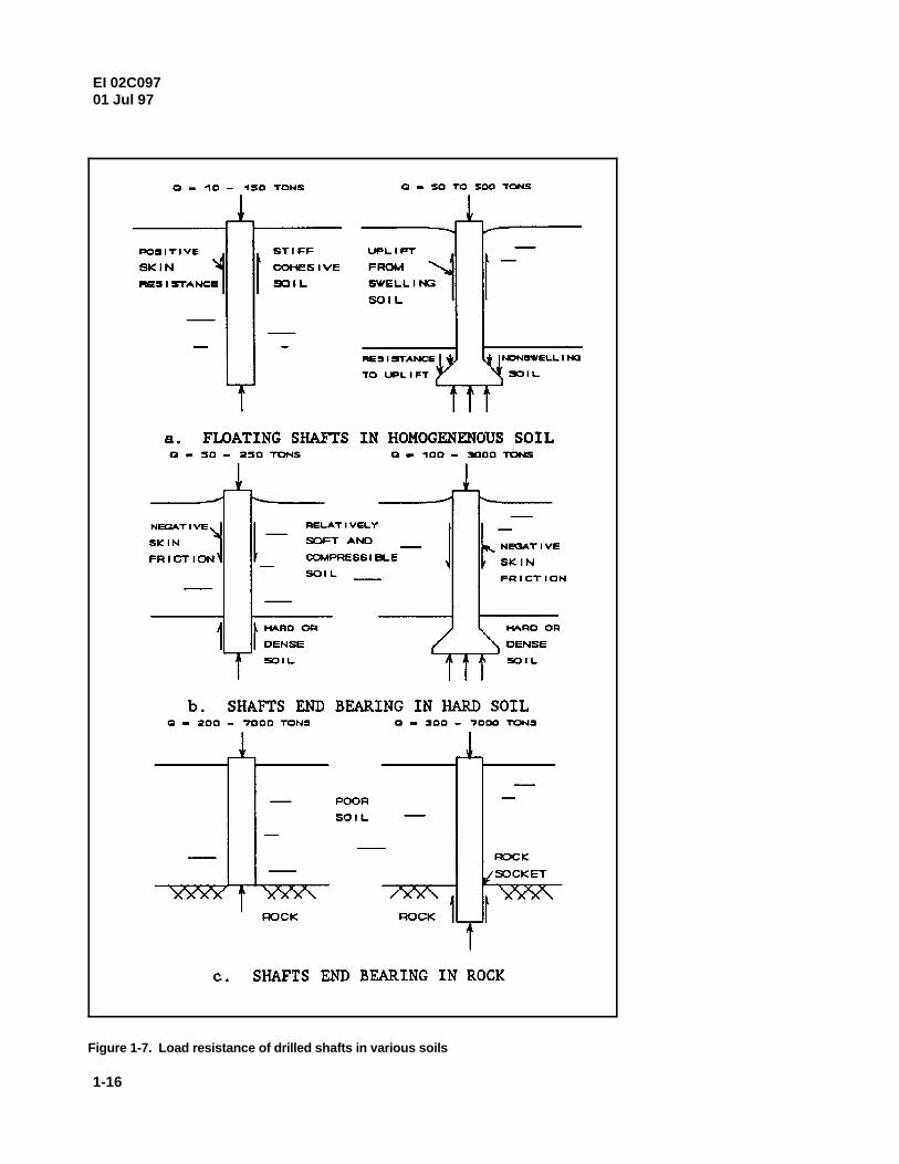
(2) Nondisplacement. Drilled shafts are especially suitable forsupporting large column loads of multistory structures and bridge abutmentsor piers. They are suitable for resisting large axial loads and lateral loadsapplied to the shaft butt (top or head) resulting from wind forces; these arealso used for resisting uplift thrust applied to the shaft perimeter through soil-shaft interface friction and from heave of expansive soil. Figure 1-7illustrates example load ranges for drilled shafts in different soils. The loadsshown are for guidance only and can vary widely from site to site.Cylindrical shafts are usually preferred to underreamed ones because of ease
EI 02C09701 Jul 97
1-11
in construction and ease in inspection. Table 1-5 provides further details of (a) Drilled shafts may secure much or all of their vertical load capacitythe applications, advantages, and disadvantages of drilled shafts. Other from frictional side resistance (Figure1-7a). An enlarged base using a bell oraspects of drilled shafts include: underream may also increase the vertical load capacity, provide uplift
resistance to pullout loads, an resist uplift thrust from

EI 02C097EI 02C09701 Jul 9701 Jul 97
1-12
Table 1-4Characteristics of Deep Foundations
Pile Type Length, ft Length, ft Width, in. Normal Stresses, psi Bending Stresses, psi Standards Advantages Disadvantages RemarksMaximum Optimum Diameter Maximum Allowable Maximum Allowable Specifications tons tons
Material Maximum Load Optimum Load
Driven Piles 150 40-100 Easy to inspect, easy to Difficult to splice, Best suited forCast-in-place 150 30-80 Butt: 12-18 Steel shell: 9,000 Compression : 0.40 f' ACI Manual of cut, resistant to displacement pile, medium-length frictionconcrete placed Concrete: 0.25 f' Tension: 0 Concrete Practice deterioration, high lateral vulnerable to damage from pilewithout mandrel capacity, capable of being hard driving
c
c
re-driven, cave-inprevented by shell
Cast-in-place concrete Tapered: 40 Tapered: 15-35 Tip: 8, Butt: # 23 Steel: 9,000, Compression: 0.40 f' ACI Manual of 75 30-60 Easy to inspect, easy to Not possible to re-drive, Best suited fordriven with mandrel Step tapered: 120 Step tapered: 40-60 Step tapered: # 17 $ 1 in. thick Tension: 0 Concrete Practice cut, easy to handle, difficult to splice, medium-length friction
Concrete: 0.25 f' resistant to decay, high displacement pile, pilec
c
skin friction in sand, vulnerable to collapse whileresistant to damage from adjacent piles are drivenhard driving
Rammed concrete 60 --- 17-26 0.25 f' --- ACI Manual of 300 60-100 Low initial cost, large Hard to inspect, Best suited wherec
Concrete Practice bearing area, resistant to displacement pile, not layer of dense sand isdeterioration, resistant to possible to form base in near ground surfacedamage from hard driving clay
Composite 180 60-120 Depends on materials Controlled by weakest --- See Note 200 30-80 Resistant to deterioration, Hard to inspect, difficult in Usual combinationsmaterials resistant to damage from forming joint are: cast-in-place
driving, high axial concrete over timber orcapacity, long lengths at H-steel or pipe pilelow initial cost
Auger Cast 60 24 --- 0.25 f' --- ACI Manual of 40 --- No displacement, low Construction difficult when Best suited whereConcrete Shafts Concrete Practice noise level, low vibration, soils unfavorable, low small loads are to be
c
low initial cost capacities, difficult to supportedinspect
Drilled Shafts 200 Shaft: # 120 --- 0.25 f' --- ACI 318 Soil: 3,000 200-400 Fast construction, high Field inspection of Best suited for largeUnderreams: # 240 Rock: 7,000 load capacity, no noise or construction critical, careful axial lateral loads and
c
vibration, no inspection necessary for small, isolated loadsdisplacement, possible to casing method where soil conditionsdrill through obstruction, are favorablecan eliminate caps
Note: Creosote and creosote treatment: “Standards for Creosoted-Wood Foundation Piles,” C1-C12, American Wood-Preservers Institute (1977-1979) Concrete: ACI Manual of Concrete Practice Timber: ASTM Annual Book of Standards, Vol 04.09, D 2899, D 3200 Steel: ASTM Annual Book of Standards, Vol 01.01, Vol 01.04, A 252

EI 02C09701 Jul 97
1-13
heave of expansive soil. Shafts subject to pullout loads or local labor rates, fuel, tools, supplies, cost and freight of pileuplift thrust must have sufficient reinforcement steel to materials, driving resistance, handling, cutoffs, caps, splicing,absorb the tension load in the shaft and sufficient skin and jetting. Jetting is the injection of water under pressure,friction and underream resistance to prevent shaft uplift usually from jets located on opposite sides of the pile, tomovements. preexcavate a hole and to assist pile penetration. Costs are also
(b) The shaft may pass through relatively soft, insurance, overhead, and profit margin. An economic studycompressible deposits and develop vertical load capacity should be made to determine the cost/capacity ratio of thefrom end bearing on hard or dense granular soil (Fig. 1-7b) various types of piles. Consideration should be given toor rock (Fig. 1-7c). End-bearing capacity should be including alternative designs in contract documents wheresufficient to support vertical loads supplied by the structure practical.as well as any downdrag forces on the shaft perimeter causedby negative skin friction from consolidating soil (Fig. 1-7b). (2) Drilled shafts. Drilled shafts are usually cost effective
(c) Single drilled shafts may be constructed with large dense sand, rock, or other bearing soil overlaid by cohesive soildiameters, typically 10 feet or more, and can extend to that will not cave when the hole is bored. Drilled shafts,depths of 200 feet or more. Drilled shafts can be made to particularly auger-placed, pressure-grouted shafts, are oftensupport large loads and are seldom constructed in closely most economical if the hole can be bored without slurry orspaced groups. casing.
(d) Drilled shafts tend to be preferred compared with f. Length.The length of the deep foundation is generallydriven piles as the soil becomes harder. Pile driving dependent on topography and soil conditions of the site.becomes difficult in these cases, and the driving vibrationcan adversely affect nearby structures. Also, many onshore (1) Driven piles. Pile length is controlled by soilareas have noise control ordinances which prohibit 24-hour conditions and location of a suitable bearing stratum,pile driving (a cost impact). availability and suitability of driving equipment, total pile
(e) Good information on rock is required when drilled offshore. Piles up to 150 feet are technically and economicallyshafts are supported by rock. Drilled shafts placed in acceptable for onshore installation.weathered rock or that show lesser capacity than expectedmay require shaft bases to be placed deeper than anticipated. (2) Drilled shafts. Shaft length depends on the depth to aThis may cause significant cost overruns. suitable bearing stratum. This length is limited by the
d. Location and topography. Location and topo-graphy hole open for placement of the reinforcement steel cage andstrongly influence selection of the foundation. Local practice concrete.is usually an excellent guide. Driven piles are oftenundesirable in congested urban locations because of noise, 8. Site and Soil Investigationsinadequate clearance for pile driving, and the potential fordamage caused by vibration, soil densification, and ground The foundation selected depends on functional requirements ofheave. Prefabricated piles may also be undesirable if storage the structure and results of the site investigation. Sitespace is not available. Other variables may restrict the investigation is required to complete foundation selection andutilization of deep foundation: design and to select the most efficient construction method.
(1) Access roads with limited bridge capacity and head conditions that can influence foundation performance androom may restrict certain piles and certain construction construction methodology. The seond phase is to evaluateequipment. characteristics of the soil profile to determine the design and
(2) The cost of transporting construction equip-ment to following:the site may be significant for small, isolated structures andmay justify piles that can be installed using light, locally a. Feasibility study. A reconnaissance study should beavailable equipment. performed to determine the requiriements of a deep
e. Economy.
(1) Driven piles. Costs will depend on driving rig rental,
influenced by downtime for maintenance and repairs,
in soil above the water table and installation in cohesive soil,
weight, and cost. Piles exceeding 300 feet have been installed
capability of the drilling equipment and the ability to keep the
The first phase of the investigation is examination of site
the construction method. These phases are accomplished bythe

EI 02C09701 Jul 97
1-14
Figure 1-6. Driven pile applications (Continued)

EI 02C09701 Jul 97
1-15
Figure 1-6. (Concluded)
EI 02C09701 Jul 97
1-16
Figure 1-7. Load resistance of drilled shafts in various soils

EI 02C09701 Jul 97
1-17
Table 1-5Drilled Shaft Applications, Advantages, and Disadvantages
Applications
Support of high column loads with shaft tips socketed in hard bedrock.
Support of moderate column loads with underreams seated on dense sand and gravel.
Support of light structures on friction shafts in firm, nonexpansive, cohesive soil.
Support of slopes with stability problems.
Resists uplift thrust from heave of expansive soil, downdrag forces from settling soil, and pullout forces.
Provides anchorage to lateral overturning forces.
Rigid limitations on allowable structural deformations.
Significant lateral variations in soils.
Advantages
Personnel, equipment, and materials for construction usually readily available; rapid construction due to mobile equipment; noise level ofequipment less than some other construction methods; low headroom needed; shafts not affected by handling or driving stresses.
Excavation possible for a wide variety of soil conditions; boring tools can break obstructions that prevent penetration of driven piles;excavated soil examined to check against design assumption; careful inspection of excavated hole usually possible.
In situ bearing tests may be made in large-diameter boreholes; small-diameter penetration tests may be made in small boreholes.
Supports high overturning moment and lateral loads when socketed into rock.
Avoids high driving difficulties associated with pile driving.
Provides lateral support for slopes with stability problems.
Heave and settlement are negligible for properly designed drilled shafts.
Soil disturbance, consolidation, and heave due to remolding are minimal compared with pile driving.
Single shafts can carry large loads; underreams may be made in favorable soil to increase end-bearing capacity and resistance to upliftthrust or pullout forces.
Changes in geometry (diameter, penetration, underream) can be made during construction if required by soil conditions.
Pile caps unnecessary.
Disadvantages
Inadequate knowledge of design methods and construction problems may lead to improper design; reasonable estimates of performancerequire adequate construction control.
Careful design and construction required to avoid defective shafts; careful inspection necessary during inspection of concrete afterplacement difficult.

EI 02C09701 Jul 97
1-18
Table 1-5 (Concluded)
Disadvantages (Concluded)
Construction techniques sometimes sensitive to subsurface conditions; susceptible to “necking” in squeezing ground; caving or loss ofground in fissured or cohesionless soil.
Construction may be more difficult below groundwater level; concrete placement below slurry requires careful placement using tremie orpumping artesian water pressure can require weighting additives to drilling fluids to maintain stability; extraction of casing is sensitive toconcrete workability, rebar cage placement must be done in a careful, controlled manner to avoid problems; underreams generally shouldbe avoided below groundwater unless “watertight” formation is utilized for construction of underreams.
End-bearing capacity on cohesionless soil often low from disturbance using conventional drilling techniques.
Enlarged bases cannot be formed in cohesionless soil.
Heave beneath base of shaft may aggravate soil movement beneath slab-on-grade.
Failures difficult and expensive to correct.
foundation designs, and the scope of in situ soil and foundation (3) Local experience. The use of local design andload tests. Required cost estimates and schedules to conduct the construction experience can avoid potential problems with certainsoil investigation, load tests, and construction should be prepared types of foundations and can provide data on successfullyand updated as the project progresses. constructed foundations. Prior experience with and applications
b. Site conditions. Examination of the site includes history, determined. Local building codes should be consulted, andgeology, visual inspection of the site and adjacent area, and local successful experience with recent innovations should bedesign and construction experience. Maps may provide data on investigated.wooded areas, ponds, streams, depressions, and evidence ofearlier construction that can influence soil moisture and (4) Potential problems with driven piles. The sitegroundwater level. Existence of former solid waste disposal sites investigation should consider sensitivity of existing structures andwithin the construction area should be checked. Some forms of utilities to ground movement caused by ground vibration andsolid waste, i.e., old car bodies and boulders, make installation of surface heave of driven piles. The condition of existing structuresdeep foundations difficult or result in unacceptable lateral prior to construction should be documented with sketches anddeviation of driven piles. Guidance on determining potential photographs.problems of deep foundations in expansive clay is given in TM 5-818-7, “Foundations in Expansive Soils.” Special attention should c. Soil investigation. A detailed study of the subsurface soilbe payed to the following aspects of site investigation: should be made as outlined in TM 5-818-1. The scope of this
(1) Visual study. A visual reconnaissance should check for size, functional intent, and cost of the structure. Results of the soildesiccation cracks and nature of the surface soil. Structural investigation are used to select the appropriate soil parameters fordamage in nearby structures which may have resulted from design as applied in Chapters 2 through 5. These parameters areexcessive settlement of compressible soil or heave of expansive frequently the consolidated-drained friction angle N forsoil should be recorded. The visual study should also determine cohesionless soil, undrained shear strength C for cohesive soil,ways to provide proper drainage of the site and allow the soil elastic modulus E for undrained loading, soil dry unit weight,performance of earthwork that may be required for construction. and the groundwater table elevation. Refer to TM 5-818-1 for
(2) Accessibility. Accessibility to the site and equipment potential heave characteristics may also be required for clay soilsmobility also influence selection of construction methods. Some of and the needed parameters may be evaluated following proceduresthese restrictions are on access, location of utility lines and paved presented in TM 5-818-7. Other tests associated with soilroads, location of obstructing structures and trees, and investigation are:topographic and trafficability features of the site.
of deep foundations in the same general area should be
investigation depends on the nature and complexity of the soil, and
u
s
guidance on evaluating these parameters.Consolidation and


EI 02C09701 Jul 97
1-21
Figure 1-8. Variation K for clay with respect to undrained shear strength and cu
overconsolidation ratio