Embed Size (px)
Citation preview
Unit 13 Calcite Business Centre 151 Industrial Road
Whitehorse, YT, Y1A 6S1, Canada Tel: 604-759-0860 Fax: 604-759-0861
Toll Free: 866-684-8894 www.capstonemining.com
April 4, 2016 Robert Holmes Director of Mineral Resources Department of Energy, Mines and Resources P.O. Box 2703 Whitehorse, YT Y1A 2C6 Dear Mr. Holmes, Please see the attached update to Minto Mine’s Underground Ground Control Plan. This update replaces the previous Underground Ground Control Plan submitted in September, 2015 (Minto Mine Ground Control Plan—Underground (rev. 1), Minto Explorations Ltd. June 2014.) If you have any questions or concerns regarding the attached document, please do not hesitate to contact me at [email protected] / 604-759-4634, or Ron Light at [email protected] / 604-759-4639. Regards, Ryan Herbert Environment Manager Minto Explorations Ltd.
Attachments:
- Ground Control Plan—Underground Operations (2015-1), Minto Explorations Ltd. December 2015.
Revision 2015-1
Ground Control Plan Underground Operations
Minto Mine, YT
Prepared by: Minto Explorations Ltd.
Minto Mine December 2015

Minto Explorations Ltd. Underground Ground Control Plan Minto Mine December 2015
Revision 2015-1 ii
Table of Contents
General Statement and Corporate Message ............................................................................ 1
Introduction ................................................................................................................................. 1
Document Layout .................................................................................................................................. 2
Accountability and Responsibilities ......................................................................................... 3
Mandatory Requirements ........................................................................................................... 5
1 Description of the Mine ....................................................................................................... 6
2 Rock Mass Characterization ............................................................................................... 7
2.1 Geological Overview ..................................................................................................................... 7
2.1.1 Geologic Structure .............................................................................................................. 7
2.2 Geotechnical Model ...................................................................................................................... 8
2.2.1 Rock Types ......................................................................................................................... 8
2.2.2 Discontinuities ..................................................................................................................... 8
2.2.3 Intact Rock Strength.......................................................................................................... 12
2.2.4 Rock Mass Properties ....................................................................................................... 13
2.2.5 In-Situ Stress ..................................................................................................................... 14
2.3 Hydrogeology .............................................................................................................................. 14
3 Design Criteria ................................................................................................................... 15
3.1 Design References ..................................................................................................................... 15
3.2 Underground Mining Methods .................................................................................................... 16
3.3 Ground Support Design .............................................................................................................. 19
3.3.1 Ground Support Elements ................................................................................................ 19
3.3.2 Ground Support Standards ............................................................................................... 20
4 Ground Support Installation ............................................................................................. 22
5 Scaling ................................................................................................................................ 23
5.1 Check Scaling Program .............................................................................................................. 23
6 Rehabilitation ..................................................................................................................... 23
7 Risk Assessment and Management ................................................................................. 24
7.1 Hazard Recognition Training Program ....................................................................................... 24
7.2 Hazard Recognition Responsibilities .......................................................................................... 24
7.3 Ground Control Communication ................................................................................................. 25
7.3.1 Review of Design Guidelines ............................................................................................ 25
7.3.2 Unusual Ground Conditions .............................................................................................. 25
7.4 Incident Response and Emergency Preparedness .................................................................... 26
7.4.1 Falls of Ground .................................................................................................................. 26

Minto Explorations Ltd. Underground Ground Control Plan Minto Mine December 2015
Revision 2015-1 iii
8 Workforce Training ............................................................................................................ 27
8.1.1 Safe Work Procedures (SWP) .......................................................................................... 27
8.1.2 Training of Workforce ........................................................................................................ 27
8.1.3 Training of Supervision ..................................................................................................... 27
9 General Practices and Procedures .................................................................................. 28
9.1 Ground Inspections ..................................................................................................................... 28
9.2 Ground Control Log Book ........................................................................................................... 28
9.3 Geotechnical Mapping ................................................................................................................ 28
9.4 Excavation Surveys .................................................................................................................... 28
9.5 Instrumentation ........................................................................................................................... 29
10 Quality Assurance/Quality Control .................................................................................. 29
10.1 Ground Support Testing ............................................................................................................. 29
10.1.1 Test Bolt Installation .......................................................................................................... 29
10.1.2 Pull Test Procedure........................................................................................................... 30
10.1.3 Documentation .................................................................................................................. 30
10.2 Ground Support Quality Assurance / Quality Control ................................................................. 30
10.2.1 Materials Management ..................................................................................................... 30
10.2.2 Task Observation .............................................................................................................. 32
11 Review of the Ground Control Plan ................................................................................. 33
11.1 Review and Updates ................................................................................................................... 33
11.2 Random Audits ........................................................................................................................... 33
11.3 External Audits ............................................................................................................................ 33
11.4 Conformance to Regulatory Requirements ................................................................................ 33
Minto Explorations Ltd. Underground Ground Control Plan Minto Mine December 2015
Revision 2015-1 iv
List of Figures
Figure 1-1: Plan view of Minto Mine (Oct.2014) — underground and open pit operations .......................... 6 Figure 2-1: Area 118 Underground Mapping .............................................................................................. 10 Figure 2-2: Area 2 Pit Mapping (SRK, 2013) .............................................................................................. 10 Figure 2-3: Minto North Pit Mapping ........................................................................................................... 11 Figure 3-1: Typical Stope Configuration ..................................................................................................... 17 Figure 3-2: Area 118 Underground As-Built (Dec. 2015) Plan View .......................................................... 18 Figure 3-3: Area 118 Underground As-Built (Dec. 2015) Looking West ..................................................... 18 Figure 10-1: DSI 30 ton Pull Test Unit ........................................................................................................ 30
List of Tables
Table 1: Major Joint Sets ............................................................................................................................. 9 Table 2: Major Structures ............................................................................................................................. 9 Table 3: Direct Shear Strength Testing on Discontinuities ......................................................................... 11 Table 4: Summary of Testing for Intact Strength Properties ....................................................................... 12 Table 5: Summary of Triaxial Testing ......................................................................................................... 13 Table 6: Rock mass parameter summary for underground mining areas .................................................. 13 Table 7: Rock mass permeability values (Hatch, 2006 after Golder, 1974) ............................................... 14 Table 8: Summary of Area 118 Geometry .................................................................................................. 16 Table 9: Summary of Area 118 Excavation Dimensions ............................................................................ 16 Table 10: Ground Support Elements .......................................................................................................... 19 Table 11: Minimum Ground Support for Development and Production Headings ...................................... 20 Table 12: Minimum Ground Support Standards for Open Stope Brow Pre-Support .................................. 21 Table 13: Ground Support Installation Specifications ................................................................................. 22 Table 14: Ground support testing frequency and specifications ................................................................. 29
List of Appendices
Appendix A Ground Support Drawings
Minto Explorations Ltd. Underground Ground Control Plan Minto Mine December 2015
Revision 2015-1 1
General Statement and Corporate Message
Capstone Mining Corp. Minto Mine maintains the Health and Safety of the people involved in
activities at the mine as the primary value entrenched into everything we do. We strive for “Safe
Production” by ensuring people clearly understand that no one is expected to work in
substandard conditions, with substandard tools or put them self at risk in any way performing their
duties at the Minto Mine. We maintain a Target: ZERO philosophy that believes all incidents are
preventable and that every effort must be made to eliminate significant accidents and reduce
minor incidents toward ZERO.
Introduction
The purpose of this Ground Control Plan—Underground Operations (GCP) is to provide a system
for the management of the ground control strategy at Capstone Minto Mine Underground
Operations. The Ground Control Plan shall:
outline systems for evaluating, designing, maintaining, and monitoring excavation stability to
prevent personal injury, damage to equipment or loss to process;
present a structure that defines core responsibilities and accountabilities;
develop and maintain a process for hazard identification and risk management with regard to
ground control and geotechnical mine design; and
introduce methods to effectively monitor and measure compliance to legislative regulations
and corporate policy through audit and review processes.
The intent of the GCP is therefore to outline the strategies aimed at eliminating or minimising the
risk of falls of ground or collapse in the underground operations which may result in fatalities,
injuries, equipment damage or loss of production.
The GCP is a live document that will change continuously with new standards, technology,
working procedures and annual reviews and applies to all personnel at the Minto Mine.
Minto Explorations Ltd. Underground Ground Control Plan Minto Mine December 2015
Revision 2015-1 2
Document Layout
The GCP has three parts:
Part One: Design
This section discusses the processes undertaken to determine the excavation design parameters,
support requirements, and proposed mining methods to be applied in the various underground
areas. This includes a summary of the site geology, rock mass characterization, minimum ground
support standards and practices to manage the predicted ground conditions.
Part Two: Implementation
This section discusses the procedures and systems for implementing the designed ground control
program. This includes Safe Work Procedures for ground support installation, a hazard
recognition program, ground control communication systems, workforce training and emergency
response.
Part Three: Monitoring and Verification
This section outlines practices and procedures for verifying the ground control design. This
includes inspections and data collection, quality assurance/quality control, and audits, updates
and reviews of the Ground Control Plan.
Minto Explorations Ltd. Underground Ground Control Plan Minto Mine December 2015
Revision 2015-1 3
Accountability and Responsibilities
Responsibilities for personnel involved with the underground operations include the following:
General Manager
The General Manager has the overall responsibility for the GCP. The General Manager shall
ensure that:
suitably trained and qualified persons are formally appointed to the following positions:
o Mine Manager;
o Chief Engineer;
o Underground Safety/Training Coordinator; and,
o Geotechnical Engineer.
Mine Manager
The Mine Manager shall ensure that:
the GCP is implemented and all regulatory requirements are met;
adequate resources are allocated and competent technical and operational personnel are
appointed.
Chief Engineer
The Chief Engineer shall ensure that:
the GCP is reviewed/updated at the required frequency;
adequate training is given to the geotechnical engineers, geologists and mine engineers;
SWPs are developed, reviewed, and modified when needed, in conjunction with the Health
and Safety Department.
Geotechnical Engineer
The Geotechnical Engineer shall ensure that:
major geotechnical aspects are adequately considered in relation to the mine design and
planning;
monitoring, auditing, and testing systems are developed and maintained;
on-going mapping, data collection and inspections are carried out to identify variations in
ground conditions; and
Minto Explorations Ltd. Underground Ground Control Plan Minto Mine December 2015
Revision 2015-1 4
ground control directives are issued for specific conditions/excavations not covered in this
plan.
Underground Superintendent and Shift Supervisors
The Mine Superintendent and Shift Supervisors shall ensure that:
the work sites and the travel ways are adequately supported through adherence to the
ground control requirements set out in the layouts;
suitable equipment is supplied and maintained to the specifications required for quality
ground control;
SWPs are implemented and monitored to ensure compliance;
any unusual ground conditions are noted and brought to the attention of the engineering
group;
all personnel receive appropriate training;
the designed support/ reinforcement is installed to the specified standards; and
reports on ground falls, and variations to ground support standards are addressed and
distributed as required.
All Operational Personnel
All operational personnel shall ensure that:
no work is undertaken without an approved plan;
only work in line with current competencies is undertaken;
SWPs are followed;
ground conditions are inspected in line with workplace inspections at every work site;
ground conditions are monitored during the shift for the presence of loose or unstable ground;
if any rock noise is heard or the ground being worked is unsafe, withdraw and barricade the
area, then immediately notify the Shift Supervisor; and
relevant information in relation to ground conditions/support is reported back to the Shift
Supervisor and Geotechnical Engineer.
Minto Explorations Ltd. Underground Ground Control Plan Minto Mine December 2015
Revision 2015-1 5
Mandatory Requirements
NO PERSON IS TO ENTER UNSUPPORTED GROUND. Supported (secured) ground is deemed
to be ground where a complete ground support system has been applied as per required
standards.
All man-entry excavations must conform to, or exceed the minimum ground control standards
specified in this document.
All ground control work must follow established SWPs.
All personnel must inspect ground conditions and check the adequacy of ground control when
entering an underground heading/access/work area.
All personnel must immediately report uncontrolled falls of ground and ground control hazards to
their immediate supervisor who will be responsible for follow up and documentation.
All reports of conditions requiring actions outside of standard work will be recorded in the Ground
Control Log Book and followed-up with a documented Workplace Inspection (WPI) to ensure the
efficacy of the remedial action.

Minto Explorations Ltd. Underground Ground Control Plan Minto Mine December 2015
Revision 2015-1 6
Part One: Design
The mine design is determined by the geological, geotechnical, and hydrogeological data
collected to characterize the Minto ore bodies. Data collected for use in mine design, and the
design processes are detailed in this section.
1 Description of the Mine
The Minto Mine is located in the Whitehorse Mining District in the central Yukon Territory. The
property is located approximately 240 km northwest of Whitehorse, the Yukon capital. Open pit
mining is currently taking place in the Minto North Pit, scheduled to be completed in Q3, 2016.
Underground mining is taking place in the Area 118 Underground, accessed by the Area 118
portal.
Figure 1-1: Plan view of Minto Mine (Oct.2014) — underground and open pit operations
Minto Explorations Ltd. Underground Ground Control Plan Minto Mine December 2015
Revision 2015-1 7
2 Rock Mass Characterization
2.1 Geological Overview
Copper sulphide mineralization at Minto is hosted wholly within the Minto pluton, predominantly of
granodiorite composition. Hood et al. (2008) distinguish three varieties of the intrusive rocks in the
pluton:
Megacrystic K-feldspar Granodiorite - gradually ranges in mineralogy to quartz diorite
and rarely to quartz monzonite or granite, typically maintaining a massive igneous
texture. An exception occurs locally where weakly to strongly foliated granodiorite is
seen in distinct sub-parallel zones several metres to tens of metres thick.
Quartzo-feldspathic Gneiss – composed of centimeter-thick compositional layering and
folded by centimetre to decimetre-scale disharmonic, gentle to isoclinal folds (Hood et
al., 2008).
Biotite-rich Gneiss.
Minto geologists consider all units to be similar in origin and are variably deformed equivalents of
the same intrusion; however, copper sulphide mineralization is found in the rocks that have a
structurally imposed fabric, ranging from a weak foliation to strongly developed gneissic banding.
For this reason all logging/mapping separates the foliated to gneissic textured granodiorite as a
distinctly unit.
Other rock types, albeit volumetrically insignificant, include dykes of simple quartz-feldspar
pegmatite, aplite; and an aphanitic textured intermediate composition rock. Bodies of all of these
units are relatively thin and rarely exceed one metre core intersections.
2.1.1 Geologic Structure
Both ductile and brittle phases of deformation are found around the Minto deposits. As noted
above, copper-sulphide mineralization is strongly associated with foliated granodiorite. This
foliation is defined by the alignment of biotite in areas of weak to moderate strain and by the
segregation of quartz and feldspar into bands in areas of higher strain, giving the rock a gneissic
texture in very strongly deformed areas. The deformation zone forms sub-horizontal horizons
within the more massive plutonic rocks of the region that can be traced laterally for more than
1,000 m. The horizons are often stacked in parallel to sub-parallel sequences.
Internally, the foliation exhibits highly variable orientations within individual horizons with the
presence of small-scale folds. The foliation is often observed to be at a high angle to contacts
with more massive textured rock units.
Late brittle fracturing and faulting is noted throughout the property. The boundary between Area
2 and Area 118 is an intermediate NE dipping fault with significant displacement of mineralization.
The easiest zone to identify (based on mineralization and texture) is the “N” zone which has up to

Minto Explorations Ltd. Underground Ground Control Plan Minto Mine December 2015
Revision 2015-1 8
66 m of vertical throw across the boundary fault. Other zones show changes in thickness and
orientation, suggesting the presence of pure strain and block rotation.
2.2 Geotechnical Model
2.2.1 Rock Types
For the majority of the underground excavations completed at Minto, Granodiorite was the major
intersected unit. As discussed in Section 1.1, mineralization typically occurs in foliated to gneissic
variations of the host Granodiorite. Experience to date indicates the waste rock typically has
slightly higher intact strength but more continuous fractures than ore, although both are variable
and often influenced by fault zones.
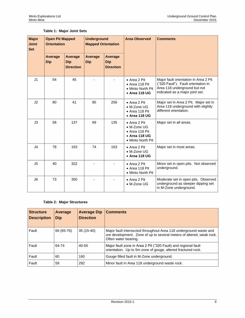
2.2.2 Discontinuities
Extensive structural mapping has been carried out in the Area 2 pit, Minto North pit, Area 118
underground, and M-Zone underground, summarized in Table 1.
In general the sets results in conditions underground varying in waste rock from moderately
blocky to very blocky and typically wedge-prone. Discontinuities in waste rock are typically very
continuous, extending larger than the excavation size. In ore, the sets are less persistent and
more widely spaced, resulting in only occasional blocky conditions. Few wedges have been
observed in ore exposures to date.
Several faults have been observed in the underground development at various orientations. Most
are relatively discrete structures with limited width and minor alteration of the wall rock; however,
several have been intersected in the Area 118 underground that have several meters of weak,
altered rock or are water-bearing indicating they are open and continuous. Fault orientations,
summarized in Table 2, typically align with joint set J1.
Minto Explorations Ltd. Underground Ground Control Plan Minto Mine December 2015
Revision 2015-1 9
Table 1: Major Joint Sets
Major
Joint
Set
Open Pit Mapped
Orientation
Underground
Mapped Orientation
Area Observed Comments
Average
Dip
Average
Dip
Direction
Average
Dip
Average
Dip
Direction
J1 54 45 - - Area 2 Pit
Area 118 Pit
Minto North Pit
Area 118 UG
Major fault orientation in Area 2 Pit (“320 Fault”). Fault orientation in Area 118 underground but not indicated as a major joint set.
J2 80 41 85 256 Area 2 Pit
M-Zone UG
Area 118 Pit
Area 118 UG
Major set in Area 2 Pit. Major set in Area 118 underground with slightly different orientation.
J3 58 137 69 135 Area 2 Pit
M-Zone UG
Area 118 Pit
Area 118 UG
Minto North Pit
Major set in all areas.
J4 78 163 74 163 Area 2 Pit
M-Zone UG
Area 118 UG
Major set in most areas.
J5 40 322 - - Area 2 Pit
Area 118 Pit
Minto North Pit
Minor set in open pits. Not observed underground.
J6 73 350 - - Area 2 Pit
M-Zone UG
Moderate set in open pits. Observed underground as steeper dipping set in M-Zone underground.
Table 2: Major Structures
Structure
Description
Average
Dip
Average Dip
Direction
Comments
Fault 66 (65-76) 35 (15-40) Major fault intersected throughout Area 118 underground waste and ore development. Zone of up to several meters of altered, weak rock. Often water bearing.
Fault 64-74 40-50 Major fault zone in Area 2 Pit (“320 Fault) and regional fault orientation. Up to 5m zone of gouge, altered fractured rock.
Fault 60 160 Gouge filled fault in M-Zone underground.
Fault 59 292 Minor fault in Area 118 underground waste rock.
Minto Explorations Ltd. Underground Ground Control Plan Minto Mine December 2015
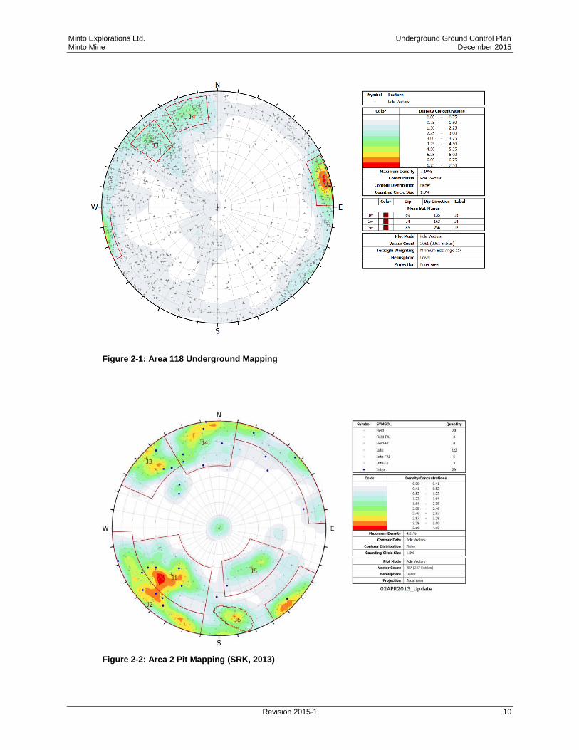
Revision 2015-1 10
Figure 2-1: Area 118 Underground Mapping
Figure 2-2: Area 2 Pit Mapping (SRK, 2013)
Minto Explorations Ltd. Underground Ground Control Plan Minto Mine December 2015
Revision 2015-1 11
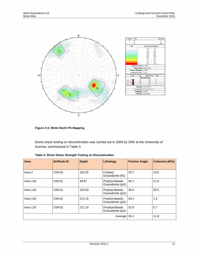
Figure 2-3: Minto North Pit Mapping
Direct shear testing on discontinuities was carried out in 2009 by SRK at the University of
Arizona, summarized in Table 3.
Table 3: Direct Shear Strength Testing on Discontinuities
Area Drillhole ID Depth Lithology Friction Angle Cohesion (kPa)
Area 2 C09-03 162.55 Foliated Granodiorite (fG)
33.7 10.0
Area 118 C09-01 49.87 Porphyroblastic Granodiorite (pG)
40.7 21.6
Area 118 C09-01 103.00 Porphyroblastic Granodiorite (pG)
35.0 20.5
Area 118 C09-01 212.15 Porphyroblastic Granodiorite (pG)
33.4 1.3
Area 118 C09-02 211.14 Porphyroblastic Granodiorite (pG)
32.9 5.7
Average 35.1 11.8

Minto Explorations Ltd. Underground Ground Control Plan Minto Mine December 2015
Revision 2015-1 12
2.2.3 Intact Rock Strength
Intact rock strength properties, summarized in the following tables, are based on the results on
drilling and testing carried out in 2009 (SRK) and 2015 (Golder).
Table 4: Summary of Testing for Intact Strength Properties
Area Lithology Condition UCS (MPa) (excluding
invalid tests)
Young’s
Modulus
(E) (GPa)
Poisson’s
Ration
Brazilian
Tensile
Strength
(MPa)
Density
(kN/m3)
tests min max mean
Area 2 Equigranular
Granodiorite (eG)
Fresh 1 103 103 103 - - - 26.3
Weathered 1 72 72 72 - - - 24.9
Foliated
Granodiorite (fG)
Fresh 1 104 104 104 47 0.23 7.6 26.5
Porphyroblastic
Granodiorite (pG)
Fresh 1 150 150 150 15 0.08 - 25.8
Weathered 1 49 49 49 - - - 26.6
Area
118
Equigranular
Granodiorite (eG)
Fresh 1 150 150 150 - - - 26.3
Foliated
Granodiorite (fG)
Fresh 8 86 165 125 67 0.30 - 26.6
Porphyroblastic
Granodiorite (pG)
Fresh 6 72 198 141 49 0.21 10.1 26.4
Weathered 1 88 88 88 51 0.22 - 26.1
Minto Explorations Ltd. Underground Ground Control Plan Minto Mine December 2015
Revision 2015-1 13
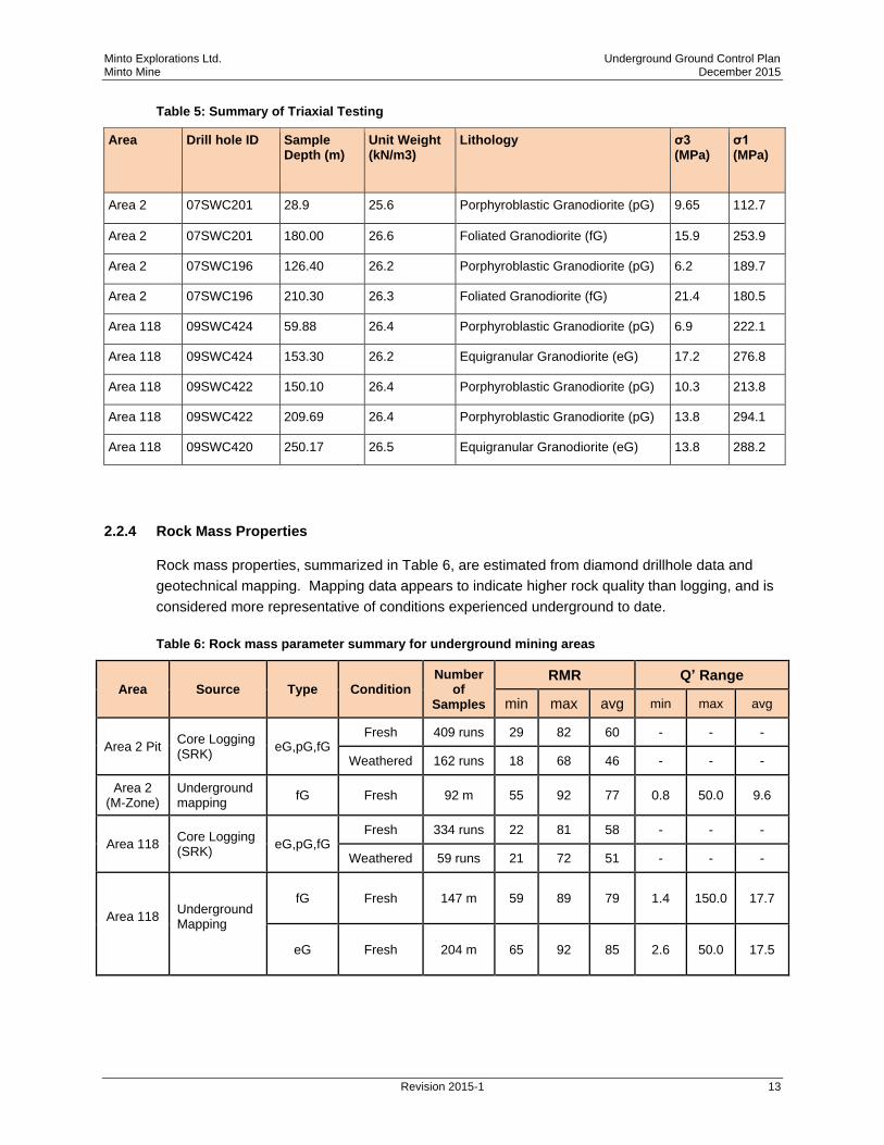
Table 5: Summary of Triaxial Testing
Area Drill hole ID
Sample Depth (m)
Unit Weight (kN/m3)
Lithology σ3 (MPa)
σ1 (MPa)
Area 2 07SWC201 28.9 25.6 Porphyroblastic Granodiorite (pG) 9.65 112.7
Area 2 07SWC201 180.00 26.6 Foliated Granodiorite (fG) 15.9 253.9
Area 2 07SWC196 126.40 26.2 Porphyroblastic Granodiorite (pG) 6.2 189.7
Area 2 07SWC196 210.30 26.3 Foliated Granodiorite (fG) 21.4 180.5
Area 118 09SWC424 59.88 26.4 Porphyroblastic Granodiorite (pG) 6.9 222.1
Area 118 09SWC424 153.30 26.2 Equigranular Granodiorite (eG) 17.2 276.8
Area 118 09SWC422 150.10 26.4 Porphyroblastic Granodiorite (pG) 10.3 213.8
Area 118 09SWC422 209.69 26.4 Porphyroblastic Granodiorite (pG) 13.8 294.1
Area 118 09SWC420 250.17 26.5 Equigranular Granodiorite (eG) 13.8 288.2
2.2.4 Rock Mass Properties
Rock mass properties, summarized in Table 6, are estimated from diamond drillhole data and
geotechnical mapping. Mapping data appears to indicate higher rock quality than logging, and is
considered more representative of conditions experienced underground to date.
Table 6: Rock mass parameter summary for underground mining areas
Area Source Type Condition Number
of Samples
RMR Q’ Range
min max avg min max avg
Area 2 Pit Core Logging (SRK)
eG,pG,fG Fresh 409 runs 29 82 60 - - -
Weathered 162 runs 18 68 46 - - -
Area 2 (M-Zone)
Underground mapping
fG Fresh 92 m 55 92 77 0.8 50.0 9.6
Area 118 Core Logging (SRK)
eG,pG,fG Fresh 334 runs 22 81 58 - - -
Weathered 59 runs 21 72 51 - - -
Area 118
Underground Mapping
fG Fresh 147 m 59 89 79 1.4 150.0 17.7
eG Fresh 204 m 65 92 85 2.6 50.0 17.5
Minto Explorations Ltd. Underground Ground Control Plan Minto Mine December 2015
Revision 2015-1 14
2.2.5 In-Situ Stress
No in-situ stress tests have been carried out on site. The magnitude and orientation of the
assumed horizontal stresses are based on expected conditions in western North America, with
the orientation of the maximum horizontal stress roughly perpendicular to the axis of the trend of
the Dawson Range. The following assumptions have been used in geotechnical analyses
(Golder, 2015):
Vertical stress = depth * gravity * rock density (assumed to be average 2650 kg/m3)
Maximum horizontal stress = 1.75 * vertical stress, oriented NE/SW
Minimum horizontal stress = 1.5 * vertical stress, oriented NW/SE
2.3 Hydrogeology
Based on underground development in Area 118 to date (down to elevation 690 m), groundwater
flow rates have been observed to be moderate with no grouting or major dewatering completed.
Seeps and inflows (up to approximately 20 GPM) have been encountered in the main ramp, 740
level access, and along the western plunge contact in Area 118. The main inflows have been
encountered in fault/fractured zones and near the footwall of the orebodies.
Several ungrouted diamond drill holes have been encountered in Area 118 which have produced
inflows, typically draining and then drying up quickly from the back but flowing continuously from
the floor at up to 20 GPM.
Based on experience in the underground and open pits to date, inflows into the remaining
planned underground are expected to be manageable with the designed sump and pumping
system.
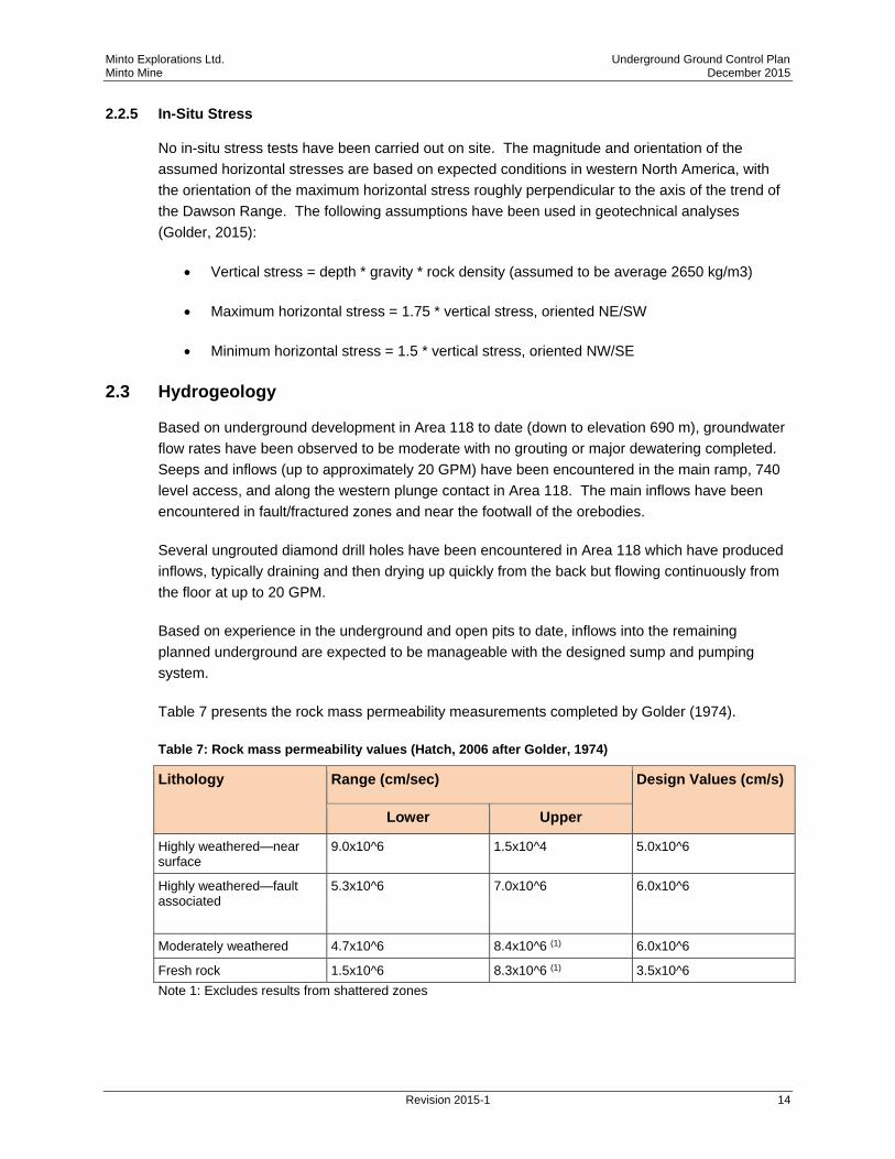
Table 7 presents the rock mass permeability measurements completed by Golder (1974).
Table 7: Rock mass permeability values (Hatch, 2006 after Golder, 1974)
Lithology Range (cm/sec) Design Values (cm/s)
Lower Upper
Highly weathered—near surface
9.0x10^6 1.5x10^4 5.0x10^6
Highly weathered—fault associated
5.3x10^6 7.0x10^6 6.0x10^6
Moderately weathered 4.7x10^6 8.4x10^6 (1) 6.0x10^6
Fresh rock 1.5x10^6 8.3x10^6 (1) 3.5x10^6
Note 1: Excludes results from shattered zones
Minto Explorations Ltd. Underground Ground Control Plan Minto Mine December 2015
Revision 2015-1 15
3 Design Criteria
3.1 Design References
Underground design parameters for Area 118 were developed based on analyses and
inspections outlined in the following documents:
Area 118 Plunge Mining Stability Assessment Summary (Golder, 2015)
Longhole Open Stope Stability Addendum – Revised Mining Heights (Golder, 2015)
Ground Control Management Plan Review (Golder, 2015)
Minto Mine Underground Reserve Update Geotechnical Input (Golder, 2015)
Geotechnical Characterization of Existing and Proposed Longhole Open Stope Mining
Areas (Golder, 2015)
Minto 118-Zone – 3DEC/DFN Analysis (Itasca, 2014)
Minto 118-Zone – FLAC3D Analysis of the Longhole Base Case Option (Itasca, 2014)
Structural Stability Analyses at Minto Mine (Itasca, 2014)
Itasca Site Visit of April 2014 at Minto Mine (Itasca, 2014)
Kinematic Analysis-Underground Excavations (Internal, 2014)
Itasca Site Visit of October 2013 at Minto Mine (Itasca, 2013)
Itasca June 2013 Site Visit at Minto Mine (Itasca, 2013)
Report on the Itasca Site Visit of 26-28 February 2013 at Minto Mine (Itasca, 2013)
Report on the Itasca Site Visit of 16-19 October 2012 at Minto Mine (Itasca, 2012)
Minto Phase VI Underground Geotech Evaluation –Draft (SRK, 2012)
Prefeasibility Geotechnical Evaluation, Phase IV (SRK, 2009)
Minto Explorations Ltd. Underground Ground Control Plan Minto Mine December 2015
Revision 2015-1 16
3.2 Underground Mining Methods
Underground mining methods, described in the following sections, were selected based on
orebody geometries, grades and geotechnical conditions. All underground mining is currently
being carried out by a mining contractor, Dumas.
The Area 118 ore body is mined using a longhole stope and pillar method (no backfill), identical to
what was previously used successfully at Minto in the M-Zone. Stoping is carried out on three
levels: 740 (now completed), 710, and 690 m (elevations). All stopes are mined on retreat and
non-entry, with mucking by remote from the undercut drifts.
Area 118 geometry is summarized in Table 8 and planned excavation sizes are summarized in
Table 9.
Table 8: Summary of Area 118 Geometry
Dimension Minimum Maximum Average
Dip (degrees) 18 45 25
Elevation (m) 680 755 -
Depth (m) 150 200 -
Length along strike (m) 25 235 145
Thickness (m) 5 35 22
Table 9: Summary of Area 118 Excavation Dimensions
Excavation Dimensions Comment
Waste development headings 5.0m W x 5.0m H Includes decline, level access, remucks
Ore development headings 6.0m W x 4.5 m H -
Pillars 5.0m W x 5-35m H
-
Stopes 10.0m W x 5-35m H -
Ventilation Raise/Escapeway 3.0m x 5.0m 70° dip
Minto Explorations Ltd. Underground Ground Control Plan Minto Mine December 2015
Revision 2015-1 17
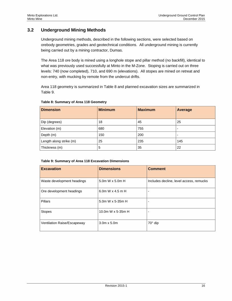
Typical stope configuration is shown in Figure 3-1, with the development drift and vertical holes
along one wall and fanned holes to the other wall.
Figure 3-1: Typical Stope Configuration
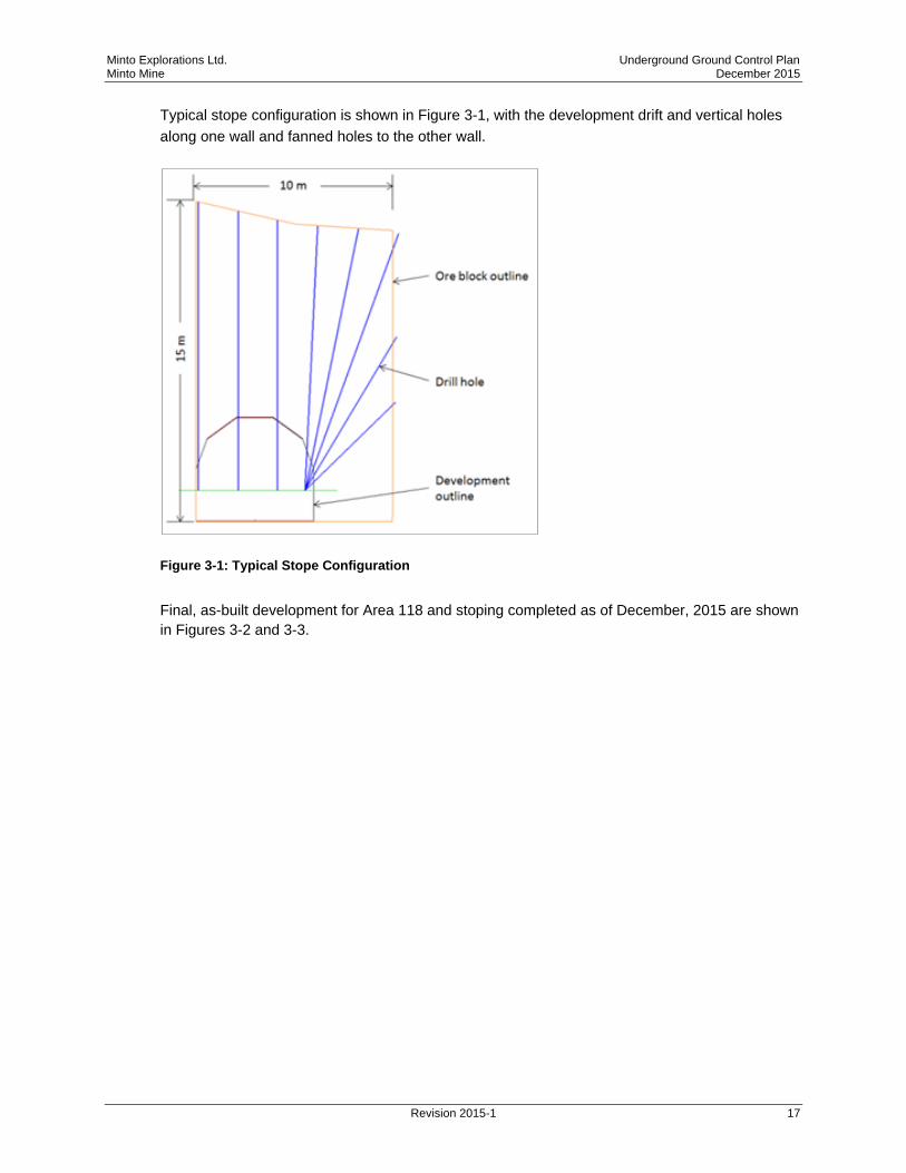
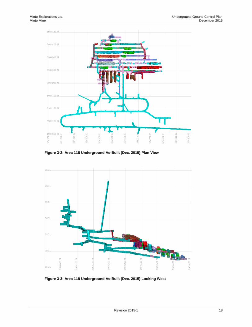
Final, as-built development for Area 118 and stoping completed as of December, 2015 are shown
in Figures 3-2 and 3-3.
Minto Explorations Ltd. Underground Ground Control Plan Minto Mine December 2015
Revision 2015-1 18
Figure 3-2: Area 118 Underground As-Built (Dec. 2015) Plan View
Figure 3-3: Area 118 Underground As-Built (Dec. 2015) Looking West

Minto Explorations Ltd. Underground Ground Control Plan Minto Mine December 2015
Revision 2015-1 19
3.3 Ground Support Design
Ground support design was carried out using a combination of empirical and kinematic analyses,
and experience to date at the Minto site.
3.3.1 Ground Support Elements
Details and specifications of ground support elements used in standard support patterns at Minto
are listed below in Table 10.
Table 10: Ground Support Elements
Support
Element
Description Minimum
Breaking
(tensile)
Strength
Comment
Bolts #6 (20mm) (3/4”) threaded rebar bolt w/ full column resin
13 tonnes -
#6 (20mm) (3/4”) forged head rebar bolt w/ full column resin
18 tonnes Used for raise development.
Super Swellex (36 mm) 24 tonnes -
Standard Swellex (27 mm) 12 tonnes Used for face bolting.
Plates Domed - 15 x 15 cm (6” x 6”), 6 mm (1/4”) - -
Resin 30mm x 610mm cartridge 30 second (fast) 180 second (slow)
- -
Mesh 6 gauge welded wire mesh ~ 2-3 tonnes bag strength
Galvanized for permanent excavations. Bright for short-term excavations.
Straps 0 gauge welded wire mesh straps - Used for stope brow support.

Minto Explorations Ltd. Underground Ground Control Plan Minto Mine December 2015
Revision 2015-1 20
3.3.2 Ground Support Standards
Support standards for development and production headings have been developed for two types
of ground, as summarized in Table 11 below. Detailed ground support drawings are provided in
Appendix A. Ground support for ventilation and escapeway raises is developed on a case by
case basis and issued by the Geotechnical Engineer.
The ground support types outlined below are minimum standards - supervisors and workers
installing the ground support should assess the conditions and place additional ground support
over and above the stated minimums if conditions warrant.
Table 11: Minimum Ground Support for Development and Production Headings
Type Span
(m)
Primary Support (minimum) Comment
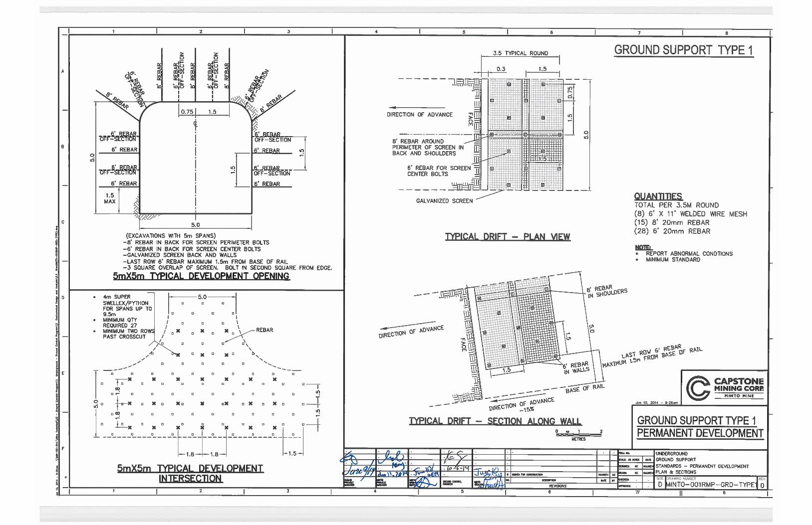
1 Development Drifts (typical ground conditions) Figure A.1
5.0 2.4 m (8 ft.) rebar in back around perimeter of mesh sheets 1.8 m (6 ft.) rebar in back and walls to pin mesh at center 1.8 m (6 ft.) rebar in walls to 1.5 m above floor 1.5 x 1.5 m bolt spacing diamond pattern Galvanized welded wire mesh to 1.5 m above floor
Life of mine infrastructure in typical ground conditions.
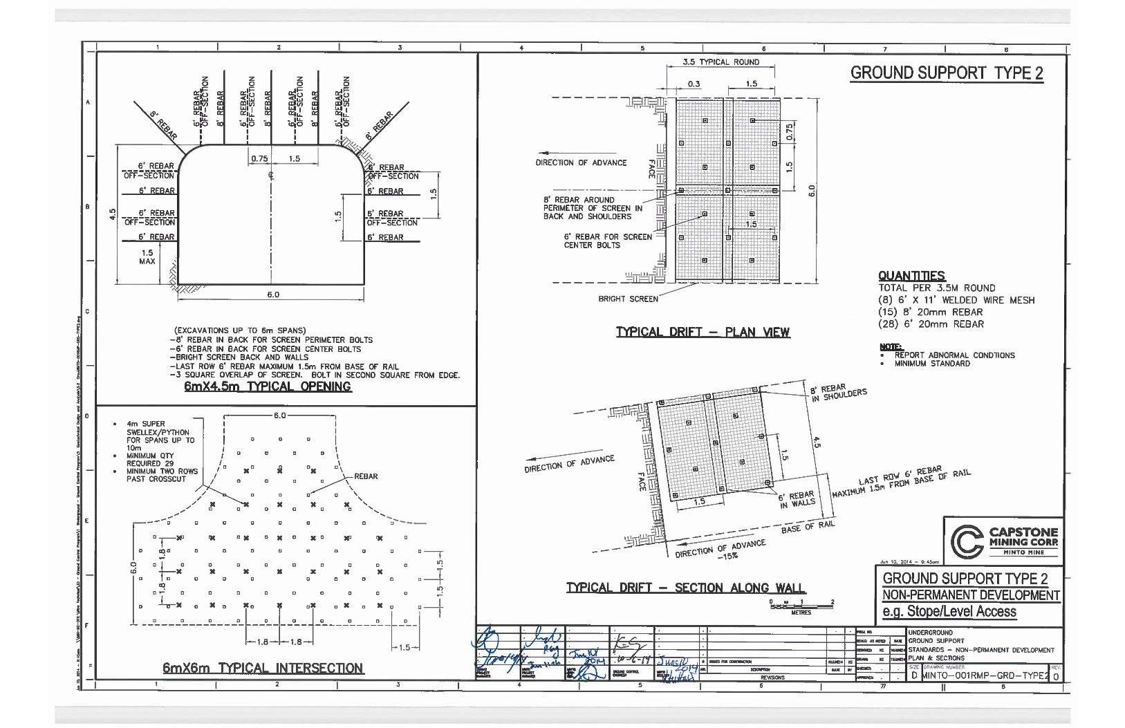
2 Production Drifts (typical ground conditions) Figure A.2
6.0 2.4 m (8 ft.) rebar in back around perimeter of mesh sheets 1.8 m (6 ft.) rebar in back and walls to pin mesh at center 1.8 m (6 ft.) rebar in walls to 1.5 m above floor 1.5 x 1.5 m bolt spacing diamond pattern Bright welded wire mesh to 1.5 m above floor
Non-permanent development (e.g. stope undercut drifts) in typical ground conditions.
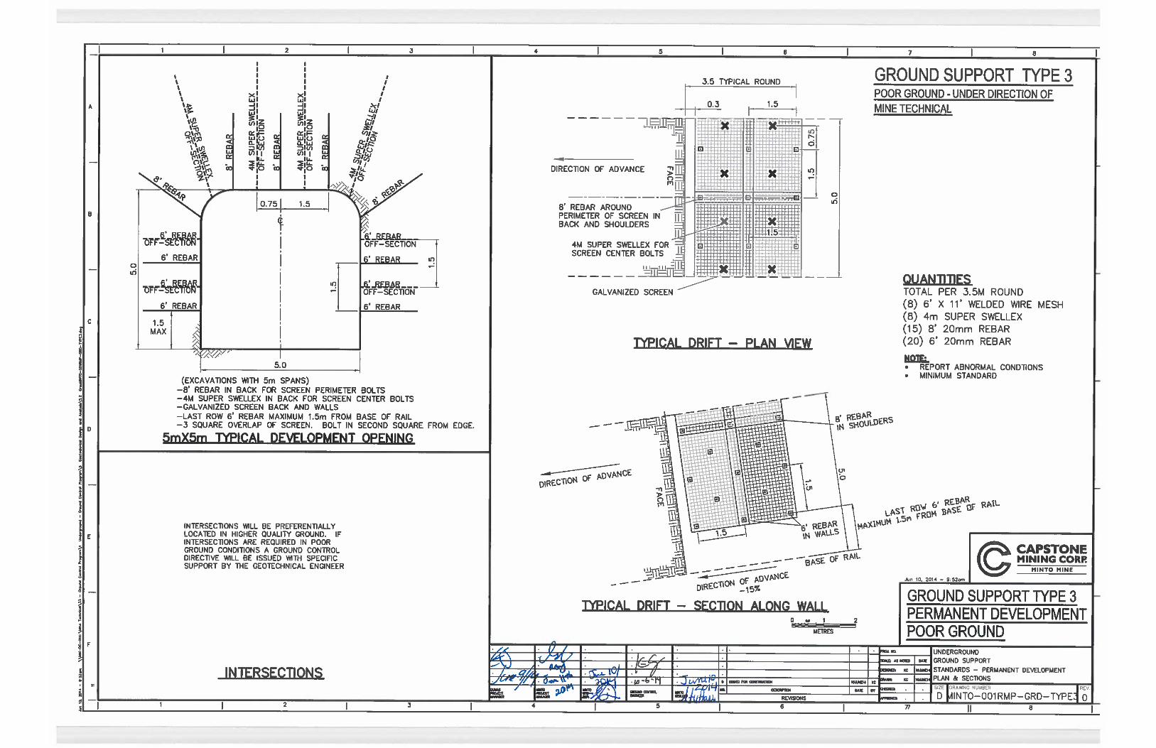
3 Poor ground – fault zones Figure A.3
≤6.0 2.4 m (8 ft.) rebar in back around perimeter of mesh sheets 3.6 m (12 ft.) Super Swellex to pin mesh at center 1.8 m (6 ft.) rebar in walls to 1.5 m above floor 1.5 x 1.5 m bolt spacing diamond pattern Bright/Galvanized welded wire mesh to 1.5 m above floor
Poor ground, typical in fault zones.
Intersection Secondary Support
1,2,3 Intersections Figures A.1-A.3
≤9.5 To be installed in addition to primary support pattern outlined above: 3.6 m (12 ft.) Super Swellex in back and shoulders 1.8 x 1.8 m bolt spacing - Installed at least two rows past the intersection in each direction.
Intersection support to be installed prior to taking wall slash, as per MIN-OP-SWP-005 Underground Intersection Development and Ground Support
Intersections are preferentially located in areas of good ground conditions. If an intersection must
be developed in an area of poor ground, a specific ground support design will be completed by
the Geotechnical Engineer and issued as a Ground Control Directive.
Minto Explorations Ltd. Underground Ground Control Plan Minto Mine December 2015
Revision 2015-1 21
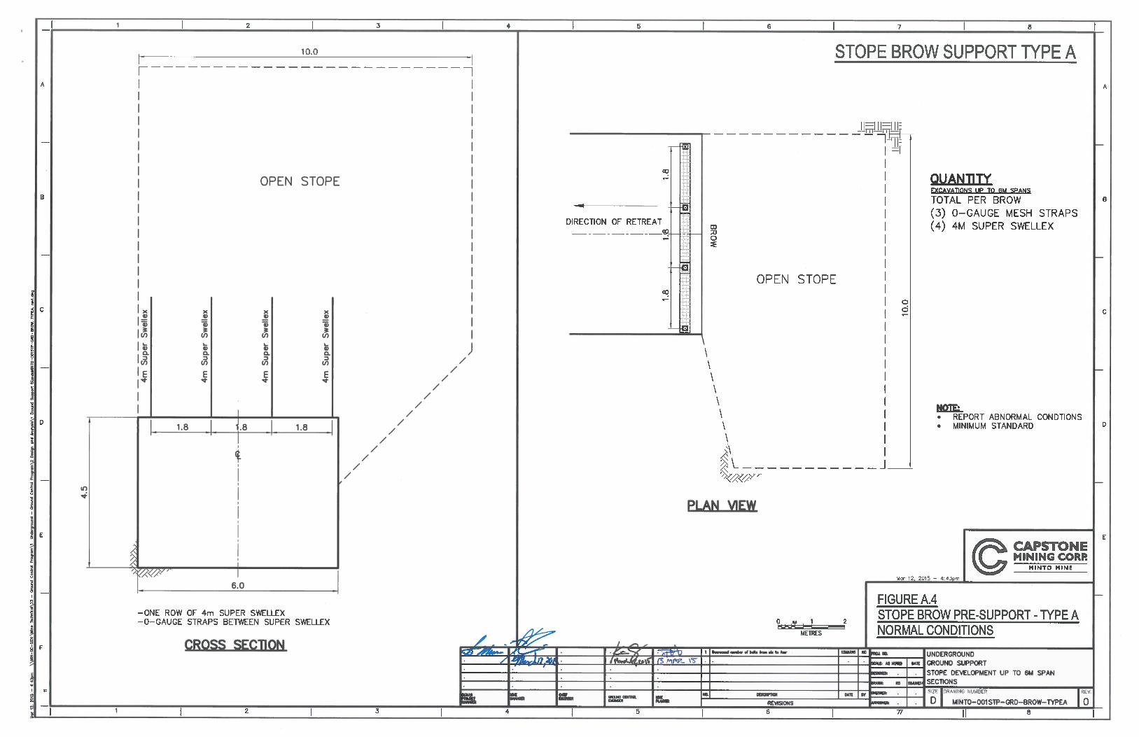
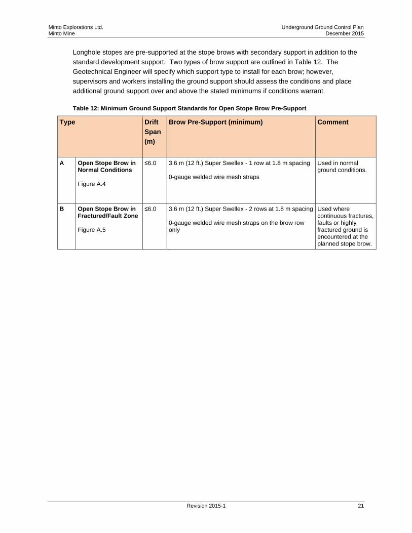
Longhole stopes are pre-supported at the stope brows with secondary support in addition to the
standard development support. Two types of brow support are outlined in Table 12. The
Geotechnical Engineer will specify which support type to install for each brow; however,
supervisors and workers installing the ground support should assess the conditions and place
additional ground support over and above the stated minimums if conditions warrant.
Table 12: Minimum Ground Support Standards for Open Stope Brow Pre-Support
Type Drift
Span
(m)
Brow Pre-Support (minimum) Comment
A Open Stope Brow in Normal Conditions Figure A.4
≤6.0 3.6 m (12 ft.) Super Swellex - 1 row at 1.8 m spacing 0-gauge welded wire mesh straps
Used in normal ground conditions.
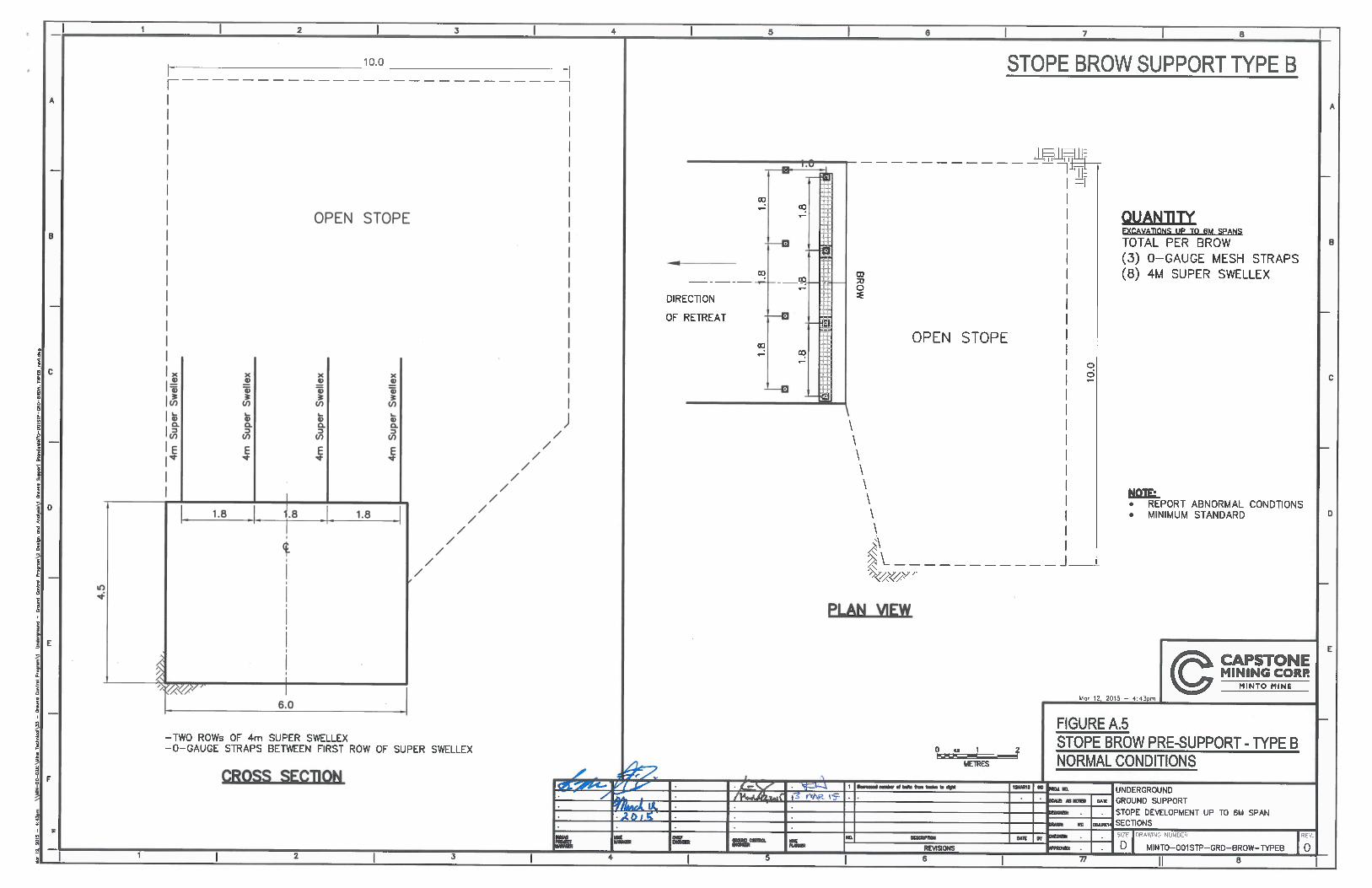
B Open Stope Brow in Fractured/Fault Zone Figure A.5
≤6.0 3.6 m (12 ft.) Super Swellex - 2 rows at 1.8 m spacing 0-gauge welded wire mesh straps on the brow row only
Used where continuous fractures, faults or highly fractured ground is encountered at the planned stope brow.

Minto Explorations Ltd. Underground Ground Control Plan Minto Mine December 2015
Revision 2015-1 22
Part Two: Implementation
4 Ground Support Installation
All operators must be trained, qualified and authorized to use the ground support installation
equipment. Ground support is installed according to the following procedures:
Installing Tensioned Rebar (Dumas, 2011)
SOP 0017 – Installation Swellex (Dumas, 2013)
SOP 0007 – Screening with Mechanized Rock Bolter (Dumas, 2013)
SWP - Underground Intersection Development and Ground Support Installation (Minto,
2013)
Ground support installation specifications are summarized in Table 13.
Table 13: Ground Support Installation Specifications
Support Element Hole Diameter Inflation
Pressure
Comment
#6 (20mm) (3/4”)
threaded rebar
26 – 33 mm - Hole length 10cm (4”) shorter than bolt length.
Rebar are installed with torque tension (TT)
shear pin nut to allow resin mixing and
torqueing in the same direction.
6 ft. long rebar - 2 fast resin and 2 slow resin.
8 ft. long rebar - 2 fast resin and 3 slow resin.
Standard Swellex 32 – 38 mm 4350 psi
(300 bar)
-
Super Swellex 43 – 52 mm 4350 psi
(300 bar)
-
Welded wire mesh - - Screen overlapped by 3 squares, with bolt
placed in second square from the edge.
Minto Explorations Ltd. Underground Ground Control Plan Minto Mine December 2015
Revision 2015-1 23
5 Scaling
Scaling will only be undertaken by individuals that have undertaken hazard recognition training
and who have been trained and certified in scaling procedures.
Scaling is to be carried out in accordance with the following procedure:
SOP 0004 - Scaling (Dumas, 2013)
Appropriate length scaling bars are available on specified machines and located where required.
5.1 Check Scaling Program
A formal check-scaling program is conducted to ensure all accessible areas underground are
check scaled at least annually for all major travel ways.
Where it is found that an area contains considerable amounts of loose, the Geotechnical
Engineer or designate is to inspect the area and ascertain if more frequent check scaling or
rehabilitation is required.
6 Rehabilitation
Areas requiring rehabilitation are identified during regular inspections by the Mine Technical
team, and by the workforce/supervisors who record the information in the Ground Control
Logbook. A rehabilitation list is maintained by the Geotechnical Engineer and stored in the
following location: X:\Mine Technical\33 - Ground Control Program\1 Underground - Ground
Control Program\4 Groundfalls and Rehabilitation\Rehabilitation. The list is provided to Dumas
supervision as part of weekly planning meetings.
Minto Explorations Ltd. Underground Ground Control Plan Minto Mine December 2015
Revision 2015-1 24
7 Risk Assessment and Management
7.1 Hazard Recognition Training Program
Hazard recognition training is to be conducted on an annual basis for every person working
underground at Minto. This training is mandatory and applies to new employees as a condition of
employment. Specific training modules for scaling and ground support are presented at these
sessions.
7.2 Hazard Recognition Responsibilities
The following sections are quoted directly from the Yukon Regulations Occupational Health and
Safety Act (in effect from November 1, 2006).
Notice of hazards 15.12
(1) Where there is a non-continuous shift operation at a mine or project, the on-coming
shift shall be warned of any abnormal condition affecting the safety of workers.
(2) The warning referenced in subsection (1) shall consist of a written record in a log
book under the signature of the person in charge of the off-going shift and be read and
countersigned by the person in charge of the on-coming shift before the workers are
permitted to assume operations in the area indicated in the record.
(3) The log book referred to in subsection (2) shall be available on request to a joint
health and safety committee representative, if any, and to a safety officer.
Underground Support 15.48
(1) Every adit, tunnel, stope, or other underground opening, where a worker may be
exposed to the danger of rock fall or rock burst while working or passing through, shall be
supported by wooden or steel support structures, casing, lining, rock-bolts or combination
of any of these to make the openings secure and safe.
Potential rock burst
(2) Where ground condition indicates that a rock burst or uncontrolled fall of ground may
occur, the condition and the corrective action taken shall be recorded in writing in the
daily log book and signed by the shift supervisor.
Work areas examined
(3) A competent person shall examine all working sections of an underground mine or
project at least once during each shift.

Minto Explorations Ltd. Underground Ground Control Plan Minto Mine December 2015
Revision 2015-1 25
Non-work areas examined
(4) Non-working sections of an underground mine or project that are not barricaded or to
which access is not prevented shall be examined at least once a month.
Scaling tools
(5) An adequate quantity of properly dressed scaling bars, gads, and other equipment
necessary for scaling shall be provided in working sections.
7.3 Ground Control Communication
Communication of ground control issues and concerns among technical, operational and
management staff, and between shifts takes place at several levels and includes:
Shift boss log book;
Ground control log book;
Face to face meeting of the shift supervisors between shifts;
Verbal communication by the crews at shift change;
Daily production meetings, and weekly planning meetings, attended by the Underground
Superintendent and Minto engineering and management staff; and,
Ground control directives issued by the Geotechnical Engineer.
7.3.1 Review of Design Guidelines
Mine plans, including week plans, are reviewed by the Geotechnical Engineer (or designate) to
assess expected geotechnical conditions and ground control aspects in the planned excavations,
considering the geotechnical data and inspections/mapping carried out. Driving layouts of
planned excavations with prescribed ground support are signed off on by the Geotechnical
Engineer (or designate) prior to mining of the heading. Where significant geotechnical conditions
are expected, e.g. fault zones, contacts, water-bearing zones, they are shown on the driving
layouts.
7.3.2 Unusual Ground Conditions
The intent of the current Ground Control Standards as outlined in this document are that all
potential ground conditions are addressed. In the event that conditions beyond those covered in
the current version of the Ground Control Standards are encountered by an operator or anyone
doing a routine inspection, the area shall be roped off immediately and brought to the attention of
the Shift Supervisor. The Shift Supervisor shall notify the Geotechnical Engineer who will inspect
the area and develop a path forward. The condition shall be noted in the Ground Control Log
Book.

Minto Explorations Ltd. Underground Ground Control Plan Minto Mine December 2015
Revision 2015-1 26
7.4 Incident Response and Emergency Preparedness
The Minto Mine Emergency Response Plan documents the incident response and emergency
preparedness procedure. This plan is updated annually by the Minto Health and Safety
Department and is stored at the following location: X:\Health & Safety\Safety Public\ERP.
7.4.1 Falls of Ground
All rock fall incidents are documented in the Ground Control Log Book. Reportable rock falls are
considered unexpected falls greater than 50 tonnes within a man-entry excavation and are fully
investigated, reported to Yukon Workers’ Compensation Health and Safety Board (YWCHSB)
and archived as per Minto incident response procedures.
Details of all reported falls of ground will be recorded electronically in a rock fall database, stored
at the following location: X:\Mine Technical\33 - Ground Control Program\1 Underground -
Ground Control Program\4 Groundfalls and Rehabilitation\Ground Falls. The following items are
recorded:
General information: location, date and time, injuries, damage
Location: depth below surface, excavation type, distance from active face
Excavation details: age of excavation, dimensions, excavation shape
Geotechnical conditions: rock quality, structure, water inflows
Ground support details: implemented support standard, rehabilitation, surface support
Failure details: dimensions, failure mechanism, types of ground support failure
Potential contributing factors: ground support, blasting, stress, ground condition, human
factor
Personnel exposure: time of occurrence, activity in area
Possible preventative actions.
To date, no unexpected falls of ground have occurred in Minto underground development.
Minto Explorations Ltd. Underground Ground Control Plan Minto Mine December 2015
Revision 2015-1 27
8 Workforce Training
Underground mining is currently being carried out by the mining contractor Dumas. As such,
workforce training consists of a combination of Minto and Dumas safety training and Safe Work
Procedures (SWPs).
8.1.1 Safe Work Procedures (SWP)
It is a requirement that employees and contractors be trained in the use of relevant safe work
procedures (SWPs) that apply to their work environment. All SWPs required for the work are
reviewed and signed off by the employees upon induction to the Minto mine site. SWPs are
linked to and used in competency-based training programs. Employees are assessed in the
workplace periodically on their understanding and compliance with SWPs through the use of
Planned Job Observations (PJO’s) performed by the supervisor. These are performed a
minimum of once per week by Dumas.
All SWPs relevant to the work must be reviewed annually at a minimum by all employees.
8.1.2 Training of Workforce
Training is presented to the general underground workforce by the Underground Safety/Training
Coordinator. This training is site specific and will include identification of ground types, structural
features such as wedges and blocks, recognition of loose, scaling, minimum support standards
and reporting unusual conditions.
8.1.3 Training of Supervision
Training is presented to underground supervisors by the Geotechnical Engineer or designate.
This training is site specific and covers all areas pertinent from a supervisory point of view such
as: selection of support types, dealing with unusual ground conditions and supervisory reporting
requirements in addition to the general training to be provided to the mining workforce.
Minto Explorations Ltd. Underground Ground Control Plan Minto Mine December 2015
Revision 2015-1 28
Part Three: Monitoring and Verification
9 General Practices and Procedures
9.1 Ground Inspections
All underground workers will inspect the ground conditions each time the workplace is entered as
per the Minto 5 point safety card system. Unusual conditions such as falls of ground, excessive
loose, adverse structures, signs of high stress, or ground support damage should be noted and
reported to the supervisor.
Routine ground inspections will be conducted by the Geotechnical Engineer and Chief Engineer
to assess the stability of mine openings, ground support performance and the quality of ground
support installation.
9.2 Ground Control Log Book
The Ground Control Log Book is maintained as a live record of ground control related issues such
as unusual conditions, falls of ground, incidents or accidents, remedial measures, etc. to ensure
the transfer of information between shifts and Engineering/Technical staff. The Ground Control
Log Book is to be updated and signed by both the finishing and oncoming shifter at each shift
change and reviewed regularly by the Geotechnical Engineer.
9.3 Geotechnical Mapping
Geotechnical mapping for rock quality and rock structure is carried out to verify rock mass
characterization assumptions (summarized in Section 2) used in the geotechnical design. This
data is reviewed regularly to identify significant geotechnical features and is summarized and
analyzed annually as part of the Ground Control Plan update.
9.4 Excavation Surveys
Regular surveys of all workings are carried out and transferred to as-built drawings. This
provides an estimate of overbreak which may indicate poor ground conditions or poor
drilling/blasting practices.
Cavity monitor surveys (CMS) are performed on all open stopes. Subsequent stopes are
adjusted to achieve the designed pillar sizes.
Minto Explorations Ltd. Underground Ground Control Plan Minto Mine December 2015
Revision 2015-1 29
9.5 Instrumentation
No instrumentation is currently installed in the Area 118 underground. Multi-point borehole
extensometers (MPBX) and blast vibration monitors were used in the M-Zone underground and
are available to be used where required.
10 Quality Assurance/Quality Control
10.1 Ground Support Testing
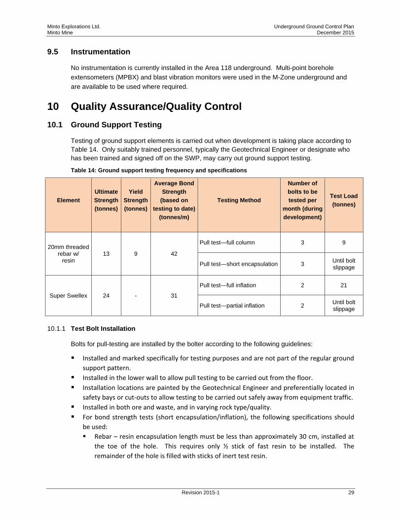
Testing of ground support elements is carried out when development is taking place according to
Table 14. Only suitably trained personnel, typically the Geotechnical Engineer or designate who
has been trained and signed off on the SWP, may carry out ground support testing.
Table 14: Ground support testing frequency and specifications
Element
Ultimate
Strength
(tonnes)
Yield
Strength
(tonnes)
Average Bond
Strength
(based on
testing to date)
(tonnes/m)
Testing Method
Number of
bolts to be
tested per
month (during
development)
Test Load
(tonnes)
20mm threaded rebar w/
resin 13 9 42
Pull test—full column 3 9
Pull test—short encapsulation 3 Until bolt slippage
Super Swellex 24 - 31
Pull test—full inflation 2 21
Pull test—partial inflation 2 Until bolt slippage
10.1.1 Test Bolt Installation
Bolts for pull-testing are installed by the bolter according to the following guidelines:
Installed and marked specifically for testing purposes and are not part of the regular ground
support pattern.
Installed in the lower wall to allow pull testing to be carried out from the floor.
Installation locations are painted by the Geotechnical Engineer and preferentially located in
safety bays or cut-outs to allow testing to be carried out safely away from equipment traffic.
Installed in both ore and waste, and in varying rock type/quality.
For bond strength tests (short encapsulation/inflation), the following specifications should
be used:
Rebar – resin encapsulation length must be less than approximately 30 cm, installed at
the toe of the hole. This requires only ½ stick of fast resin to be installed. The
remainder of the hole is filled with sticks of inert test resin.

Minto Explorations Ltd. Underground Ground Control Plan Minto Mine December 2015
Revision 2015-1 30
Super Swellex – inflation length must be less than approximately 1m, inflated at the toe
of the hole. The remaining length at the collar of the hole is sleeved to prevent
inflation.
10.1.2 Pull Test Procedure
Pull tests are conducted according to the SWP ENG-SWP-010 Rock Bolt Pull Testing. If tests fail
to meet the set criteria, further tests will be conducted to verify that the problem is not
widespread. If the problem is widespread, the area will be shut down and an investigation will be
carried out by Minto Mine Technical to ascertain the cause of the failures and develop
rehabilitation/corrective actions.
10.1.3 Documentation
Records of all tests are documented in a master Excel spreadsheet: X:\Mine Technical\33 -
Ground Control Program\1 Underground - Ground Control Program\7 Underground Monitoring,
Geologic Mapping, Reporting\11.2 Underground Monitoring\Pull Testing. Information recorded
includes bolt type, location, age, rock type, test result and description. A memorandum is issued
monthly communicating test results and pertinent information to Minto Mine Technical and
underground operations staff.
10.2 Ground Support Quality Assurance / Quality Control
10.2.1 Materials Management
Regular checks are required to ensure that all ground support materials are of a suitable standard
and quality, fit for intended purpose, and are stored in accordance with manufacturers’
recommendations.
Resin Storage and Handling
The most sensitive ground support element is resin, which should be stored and handled with the
following guidelines:
Resin should be stored in a cool and dry location, avoiding direct sunlight and rain.
Excessive heat reduces the shelf life of the resin.
Stock must be rotated. The resin that is first in should be first out. Out-dated resin
should not be used. Resin typically has a one year shelf life, but 1-2 month inventories
are the best way to manage resin.
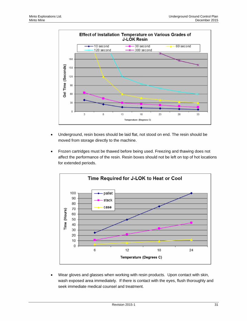
Resin performance is highly sensitive to installation temperature.
Minto Explorations Ltd. Underground Ground Control Plan Minto Mine December 2015
Revision 2015-1 31
Underground, resin boxes should be laid flat, not stood on end. The resin should be
moved from storage directly to the machine.
Frozen cartridges must be thawed before being used. Freezing and thawing does not
affect the performance of the resin. Resin boxes should not be left on top of hot locations
for extended periods.
Wear gloves and glasses when working with resin products. Upon contact with skin,
wash exposed area immediately. If there is contact with the eyes, flush thoroughly and
seek immediate medical counsel and treatment.
Minto Explorations Ltd. Underground Ground Control Plan Minto Mine December 2015
Revision 2015-1 32
10.2.2 Task Observation
Task observations will be carried out by the Mine Technical group on ground support installation
on a regular basis (minimum one per month). When warranted, findings will be communicated
through Ground Control Directives and/or the Ground Control Log Book. Typical verification
checks may include:
Confirm screen overlap is sufficient.
Visual check of adherence to bolting pattern as per ground support standard.
Check that adequate scaling is carried out prior to ground support installation.
Check that bit size is within recommended size range.
Check of Swellex pump pressures.
Check that correct resin cartridges are being used (fast vs slow).
Observe resin spin time and delay time prior to tensioning.
Check of rebar tensioning torque.
Minto Explorations Ltd. Underground Ground Control Plan Minto Mine December 2015
Revision 2015-1 33
11 Review of the Ground Control Plan
11.1 Review and Updates
The Chief Engineer will ensure a review of the Ground Control Plan at the following
milestones/occurrences:
Immediately following a ground control related injury to any employee/contractor/visitor;
Immediately following a ground control related near miss incident;
As soon as possible following any significant change in mine design, ground conditions or
excavation stability; and,
Annually.
The Chief Engineer will ensure that the review/update is carried out by a suitably qualified person.
Following a review of the Ground Control Plan, the Chief Engineer (or designate) will ensure the
review outcomes are communicated to the workforce and the Ground Control documentation is
updated in a timely manner.
11.2 Random Audits
Random audits of ground control are conducted by the Geotechnical Engineer, or nominee to
monitor compliance with the requirements of the Ground Support Standards and Safe Work
Procedures.
11.3 External Audits
An independent audit of the Ground Control Plan is required at least every two years. Initially this
independent review is to include an external consultant, but later could be an internal consultant
accompanied by an appropriate person that is familiar with the use of the GCP.
11.4 Conformance to Regulatory Requirements
The Geotechnical Engineer is to ensure that any new legislation or developments that affect best
practice in ground control are taken into account and where relevant, incorporated into the
revised GCP. Mining legislation requires emphasis on keeping track of new developments and
design tools. This will involve liaison with internal and external consultants.

Minto Explorations Ltd. Underground Ground Control Plan Minto Mine December 2015
Revision 2015-1
Appendix A
Ground Support Drawings