Embed Size (px)
Citation preview

UML Modeling of User and Database
Interaction
JESUS M. ALMENDROS-JIMENEZ1 AND LUIS IRIBARNE2,*
1Information System Group, University of Almerıa, 04120 Almerıa, Spain2Applied Computing Group, University of Almerıa, 04120 Almerıa, Spain
*Corresponding author: [email protected]
In this paper, we will present a design technique for user and database interaction based on UML.
User interaction will be modeled by means of UML state diagrams, and database interaction by
means of UML sequence diagrams. The proposed design technique establishes how to integrate
both diagrams in order to describe the user interface and database interaction of a business soft-
ware system. A case study of an Internet Book Shopping system will be shown to illustrate the
proposal.
Keywords: UML; software modeling; human–computer interaction; model driven development
Received 7 September 2007; revised 26 February 2008
INTRODUCTION
Domain-specific modeling (DSM) [1] is a way to design and
develop systems that use Domain-specific languages (DSLs)
to model the different elements of a software system. Such
systems focus on higher-level abstractions and models, and
architects work with domain concepts. A DSM environment
allows us to specify constructs and rules for modeling a
target domain. Examples of DSM environments are
MetaEditþ or Eclipse.
On the other hand, Model-driven development (MDD) is a
framework of techniques for software design based on visual
modeling. The advantages of software design based on MDD
have been recognized by several authors [2–5]. MDD has
arisen in the context of the Unified modeling language (UML)
[6]. UML provides a visual language for the description of
the artifacts of a software system. UML is a modeling language
suitable for high-level modeling in which constructions can be
mapped into code with the help of Model transformation tools
[3, 5], integrated in a DSM environment.
UML is a visual language equipped with a rich set of
diagrams. Each kind of UML diagram provides a different
perspective of the system to be developed. For instance, use
case diagrams are suitable for requirement capture, state
diagrams describe system states and transitions to be triggered
for state changes and sequence diagrams are intended to be
used for object-interaction design: message exchange and
execution threads.
A DSM environment should provide architects support for
developing business applications in which user interactions
and database interactions are the main tasks. In addition,
MDD techniques can be used for business software modeling.
User interactions are achieved by means of user interfaces,
in which interactions can be classified into input and output
interactions. In addition, user interactions are accomplished
by means of client or server-side processes. Client-side pro-
cesses usually handle user interface components and server-
side processes usually involve database interactions. Database
interactions consist in data requesting (and data updating)
from (to) a database server. Database interactions are
usually due to user interactions. Database interactions
involve client-side processes (user interface components
updating) and server-side processes (database updating and
requesting).
In a typical client-server application the user interacts with
the system through a user interface. Typically, this interface
can consist in static (i.e. HTML documents), active (i.e.
Applet, Javascript) or dynamic (i.e. JSP, PHP, CGI) tech-
nologies in which there is an interaction with a database.
Modern user interface technologies (Web 2.0) have the
capability of storing information about user interaction at
the client-side: some user interface components are containers
storing particular data for each user. For instance, a shopping
system stores the user shopping cart during the purchase
process.
In such a context, a suitable software architecture should
separate concerns such as the presentation logic, navigation/
interaction, business logic and workflows, and database
transactions. One of most relevant proposals for such an
THE COMPUTER JOURNAL, 2008
# The Author 2008. Published by Oxford University Press on behalf of The British Computer Society. All rights reserved. ForPermissions, please email: [email protected]
doi:10.1093/comjnl/bxn028
The Computer Journal Advance Access published May 21, 2008
architecture is the Model-view-controller (MVC) pattern [7].
The MVC pattern is a design pattern for the organization of
user interface programs. In MVC the model components
handle the state of objects used by the user interface. The
view components are responsible for the user interactions
that display the state of the model components. Finally, the
controllers handle the user interactions, modifying the state
of the models. MVC has been successfully applied for user
interface design (see for instance [8, 9]).
Following an MVC architecture, the model components are
the user interfaces (at the client-side) which interact with the
databases (at the server-side). The user interface requests
data (with the help of the controller components) from the
database and shows (with the help of the view components)
to the user the output data. The server executes the request
at the server-side and sends the data to the user interface
(with the help of the controller components), which can
update some user-interface containers with the output data,
or can update the database server with the input data. In
some cases of user interface technologies, the server sends
the user interface to the client properly by dynamically
generating the user interface.
The previous MVC architecture is complex enough
to be considered as a UML profile, and user and database
interactions should be modeled in UML in separate diagrams.
User interface design has been already proposed as a UML
profile in some works [10, 11].
In this context, user interactions, and also database
interactions, should be modeled by means of some kind of
UML diagrams. UML should be used for describing these
kinds of models in detail, and user and database interaction
UML views should be integrated. Such a design technique
can be integrated in a DSM environment providing UML
modeling and model transformation.
But now, would the models be consistent with each other?
The answer to this question leads us to the definition of a
design technique for user and database interactions based on
UML, which is the main aim of this paper. Model consistence
means, therefore, that each design technique should comp-
lement each other according to MDD principles.
1.1. Contributions of the paper
In this paper we will present a design technique for user and
database interactions based on UML. User interfaces and
user interactions will be modeled in UML by means of class
and state diagrams. Databases and database interactions
will be modeled by means of class and sequence diagrams.
In addition, the use case diagram is used for modeling
user requirements. The proposed design technique can be
summarized as follows.
– We build a use case diagram in which we identify actors
and use cases. From each use case we build the so-called
user interaction diagram which is a specialized version of
the UML state diagram. In the user interaction diagrams,
states represent output interactions (and data requesting)
and transitions represent input interactions (i.e. user
clicks). Therefore user interaction diagrams represent
the dialogue model of the software to be designed.
– From the set of user interaction diagrams a new diagram
called user interface diagram can be built, which is a
specialized version of the use case diagram, and describes
the set of windows of the system to be developed. In some
sense, the user interface diagram can be considered as a
user task model given that it represents the set of tasks
that the user accomplishes, each associated to a separate
window.
– From the user interaction diagrams, a class diagram can
be built representing the so-called user interface class
diagram containing the set of user interface components
for each window. Once the user interface class diagram
is built, we can proceed to build a new class diagram
with classes representing the database components, the
so-called database class diagram.
– Finally, we can build the so-called database interaction
diagram, which is a specialized version of the UML
sequence diagram. The database interaction diagram
represents the interactions of the objects. Objects that
interact in a database interaction diagram can be classi-
fied into user interface objects and database objects.
Database interaction diagrams describe how user inter-
face and database components collaborate to accomplish
the user tasks. Some use cases can be described by means
of user interface objects, and therefore these are
client-side use cases. User interface containers can be
considered as (small) databases at the client-side. Some
other use cases can be described by means of user
interface and database objects, and therefore these are
server-side use cases. In addition, some database
interaction diagrams can be used to describe business
logic; that is, some of the objects involved in the
database interaction diagrams can achieve business
logic tasks. Therefore, database interaction diagrams
can be used for describing the manipulation of persistent
and non-persistent data in the software to be developed.
– Database interaction diagrams complement user interac-
tion diagrams in the following sense. User interaction
diagrams describe user interface interactions (input and
output data) but each user interaction has usually an
effect in user interface and database components which
is described by means of database interaction diagrams.
– One of the main contributions of the proposed technique
is the correspondence between the use case diagram (use
cases and use case relationships) and the UML models
developed from the use case diagram. Use case relation-
ships (inclusion and generalization relationships) are
also identified in (and mapped into) state and sequence
Page 2 of 20 J. M. ALMENDROS-JIMENEZ AND L. IRIBARNE
THE COMPUTER JOURNAL, 2008
diagrams (i.e. user and database interaction diagrams). In
other words, we distinguish in our approach more
general and particular tasks (i.e. use cases) and inclusion
of tasks (i.e use cases). Now, state and sequence dia-
grams specify the set of states (i.e. sequence of steps)
to be achieved for each task (use case) and they can be
mapped into the use case relationships.
Therefore our proposed technique accommodates to the
MVC architecture in the following sense. Dialog modeling
is described by means of user interaction diagrams; therefore
controller components can be described by transitions in
user interaction diagrams. In addition, view components are
also described in the user interface diagrams and the user inter-
face class diagram. The collaboration between controllers and
view components is described by means of the user interaction
diagrams and database interaction diagrams. Finally, model
components are present in the user interface class diagram
and the database class diagram.
Our design technique can be considered as an extension of
our previous work of user interface design [12–14] in which
the database interaction view completes the design of a
client–server application. In addition, our design technique
is influenced by our previous work [15] about the description
of use case relationships by means of sequence diagrams.
1.2. Related work
In the literature there are several proposals for adopting UML
for user interface modeling. Some of them also cover database
interaction modeling. The kind of user interfaces modeled in
UML ranges from traditional WIMP (Windows, Icons, Menus
and Pointers) interfaces to Web interfaces including Web navi-
gation. Some of them integrate Web interface modeling with
database interaction modeling using UML state and sequence
diagrams. Finally, there are UML proposals about combination
of state and sequence diagrams in different contexts. Next, we
will review the most relevant contributions in these lines.
1.2.1. User interface modeling tools
With respect to user interface modeling, in most cases UML is
mixed with other non-UML notations. Most recent works have
been developed in the context of MDD-based techniques, and
there are many relevant proposals with tool support (see [16]
for a survey). Among the closest to our work, TERESA [17,
18] (Transformation Environment for InteRactivE System
RepresentAtions) is a tool designed for the generation of
user interfaces for multiple platforms from task models
designed using ConcurTaskTrees (CTT). Our user interface
diagram has some similarities with the CTT diagram. By
means of the proposed specialization of the use case
diagram we might decompose tasks into subtasks, but a
more fine and accurate decomposition is reached by means
of user interaction and database interaction diagrams.
Although the aim of TERESA project is similar to ours, the
approaches are different in both modeling language and
rules of design.
Partially based on UML, WISDOM (Whitewater Interactive
System Development with Object Models) [19–22] is a proposal
for user interface design based on UML. WISDOM mainly uses
UML but the authors have also adopted the ConcurTaskTrees
for task modeling. The domain model in WISDOM captures
the objects, and the business model describes each user task
and entities involved in such tasks. The business model in
WISDOM is represented by the UML use case model and the
domain model by means of a stereotyped class diagram. Use
case model is completed by state diagrams in order to describe
the service that the system offers its users. The design model
offers a separation between application level and user interface.
The dialog model is specified by means of ConcurTaskTrees.
Our model is similar to WISDOM in the use of the use case
diagram as a starting point of the user interface design. In
addition, a class diagram is also used in our approach for
describing objects interacting with the user in the user interface.
However, in our approach task/dialog modeling is achieved
by means of a specialized version of the use case diagram,
completed by means of state diagrams and sequence diagrams,
instead of the non-UML diagram CTT.
Fully based on UML, UMLi [11, 23, 24] proposes an
extension of UML for user interface design. It distinguishes
application objects and interaction objects. In our case we
also distinguish both. Application objects are described in our
approach by means of the database class diagram and the data-
base interaction diagrams. Interaction objects are described in
our approach by means of the user interaction diagrams and
the user interface class diagram. UMLi proposal is very
similar to ours in the adoption of UML diagrams for user inter-
face and task modeling design. However the extensions are
different. In our case, we focus more on the use case
diagram, use cases and use case relationships. Use case relation-
ship identification and mapping into state and sequence dia-
grams is one of the most relevant contributions of our proposal.
1.2.2. WIMP and Web modeling
With respect to the kind of user interfaces to be modeled, most
of UML proposals model traditional user interfaces, those
based on WIMP interfaces, but there are recent proposals
concerned with the design of modern user interfaces (Post-
WIMP interfaces) based on hypertext with dynamic content.
For instance, there are interesting proposals [10, 25–30]
in the context of UML about user interface design of Web
applications. Most cases focus on class diagrams for naviga-
tion modeling of Web applications. The most relevant contri-
bution in this framework is [10], in which a rich set of
technologies for Web design are used and modeled. Similarly,
the work of [29] introduces navigation modeling integrated
with sequence diagrams to describe the interaction of user
interface components.
UML MODELING OF USER AND DATABASE INTERACTION Page 3 of 20
THE COMPUTER JOURNAL, 2008
In our case, we focus on WIMP interfaces; in particular, we
have adapted our technique to Java technologies: the Java
swing package and the Java Database Connection (JDBC)
library. In other words, we have adopted a Java client-server
architecture for the system design. However, we believe that
it is not a strong restriction of our proposal, and we expect
to extend our proposal to post-WIMP user interfaces in the
future. In addition, we will partially describe user interface
components by means of sequence diagrams, and partially
by means of state diagrams.
1.2.3. State and sequence diagrams for UI modeling
The use of state diagrams for user-interface design is not new;
there are well-known proposals [31], and some more recent
ones too [32]. For database interaction modeling there are
proposals of using state machines like [33], and that which
integrates both (i.e. user-interface and database interaction
modeling) can be found in [34]. Although the proposal of
[34] relies on such integration, their framework focuses
more on Web applications. However, there are some interest-
ing points of the quoted work.
First, they distinguish between the entities, from which the
presentation unit retrieves the content, and the selectors,
which are predicates that describe the objects contributing to
the content of the presentation unit. Secondly, they distinguish
contextual links connecting two presentation units and non-
contextual links that represent links between pages. Finally,
they support the specification of services and content manage-
ment operations requiring write access over the information
hosted in a site, and the specification of update operations of
entities.
Our approach has some similarities with the cited [34] in the
way of structuring user interface and database interaction
modeling. Entities in our case will be non-persistent con-
tainers, and selectors will be specified by means of database
interaction diagrams applied to non-persistent containers.
In addition, our database interaction diagrams are able to
specify the service that the database servers provide to
clients (i.e. user interfaces).
1.2.4. State and sequence diagram integration
Finally, there are some works in the context of UML where the
transformation of state diagrams into sequence diagrams has
been studied [35–37]. Our work proposes a combination of
state and sequence diagrams to describe user and database
interaction, and both design techniques are complementary
to each other. In other words, rather than transforming one
diagram to another, we are more concerned in the description
of complementary views of the same artifacts. However, the
quoted works have some similarities with our work once
they show that the task modeling with state diagrams can be
transformed, and therefore complemented by task modeling
with sequence diagrams.
Finally, an interesting proposal in this line is [38], where
they provide descriptions of use cases by means of state
diagrams, integrated with sequence diagrams. The validation
and verification of use case specifications are the main goals
of the quoted work. In our case, we are also concerned with
the consistence of models represented by state and sequence
diagrams for user and database interactions. Basically, the
consistence is forced by following a design technique in
which a set of rules for a correct design is formulated. Vali-
dation and verification of such rules could be included as
part of the DSM tool supporting the design technique.
1.3. Previous work
The proposed design technique has as basis our previous work
on user interface modeling [12–14] and sequence diagram
modeling [15] from use cases. This work presents a significant
extension of our previous works by considering (and
completing) the user interface view with a database view, in
which user interface components interact with database/user
interface container components. In our previous papers [13]
we were more concerned with the identification of user
interface components and modeling of user interactions.
However we omitted how the user interface and database
components are consulted/updated and how the database
interactions are modeled. Here we fully describe these aspects
of the proposed design technique. In addition, the main contri-
butions of our proposals was the identification of use case
relationships, and how such relationships should be represented
in state [12] and sequence diagrams [15]. Following the same
ideas as [12, 15], here we will identify use case relationships
and we will map such relationships into both design techniques.
In addition, in our previous work [14] we were concerned with
code generation for user interfaces. Here, we will discuss how
the introduction of database interactions could complete the
code generation with database code.
1.4. Structure of the paper
The structure of the paper is as follows. Section 2 will introduce
an integrated design technique for user interface and database
interactions. Section 3 will present a case study of an Internet
Book Shopping (IBS) system, to describe the proposed design
technique in detail and will discuss some aspects about code
generation. Section 4 will conclude and present future work.
2. UML MODELING OF USER AND DATABASE
INTERACTION
In this section we will present the steps of the proposed design
technique for UML modeling of user and database interaction.
As case study, we will consider an Internet Book Shopping
(IBS) system. Such system describes how Customers and
Page 4 of 20 J. M. ALMENDROS-JIMENEZ AND L. IRIBARNE
THE COMPUTER JOURNAL, 2008

employers (i.e. a Manager and an Administrator) interact with
the system to accomplish the tasks of purchasing and catalog
administration. To illustrate the steps of the proposed tech-
nique we will focus on the Customer’s side, in particular, in
the Purchase task. A sketch of the steps to be followed is
shown in the Fig. 1. The case study will be described in
detail in the next section. The proposed design technique
can be summarized as follows.
2.1. Building a use case diagram
The first step of the proposed technique consists in building a
use case diagram, in which actors and use cases are identified.
For each actor a set of use cases is specified describing
each task that each user can accomplish in the software to
be developed. Actors and use cases (i.e. tasks) are connected
by means of associations. In addition, generalization rela-
tionships between actors, and generalization and inclusion
relationships between use cases can be identified, respectively.
Generalization between actors means that some actors are
more general than others: the particular actors add new tasks
to more general actors. Generalization between use cases
denotes more general and particular tasks. A task is more
particular than another whenever the states or steps to be
achieved by the task are more particular or the set of states
or steps is bigger. Finally, use cases can be compared by
means of the inclusion relationship, showing that some use
cases are pieces of another use case. In other words, one of
the states or steps of one use case is another use case.
One of the most relevant contributions of our work is the
mapping of use case relationships into state (and sequence)
diagrams relationships. In other words, inclusion and
generalization of use cases can be mapped into certain
elements of state and sequence diagrams.
Figure 1 shows a piece of the use case diagram of the case
study, describing an association between the actor Customer
and the task (i.e. use case) Purchase.
2.2. Building user interaction diagrams
The second step consists in building state diagrams for
each use case. We build a specialized version of UML state
diagrams for the description of the user interface. This
specialized version is called user interaction diagram.
Assuming that each use case (i.e. task) needs a user
interface (i.e. window); each window is described by means
of a user interaction diagram in which states represent
output interactions (and data requesting) and transitions
represent input interactions (i.e. user clicks).
Output and input interactions are labeled by means of a
UML stereotype representing which kind of user interface
component will be used for the interaction. In a Java swing-
based architecture, they will be buttons, boxes, lists and text
area components.
User interaction diagrams can be compared by means of
inclusion and generalization relationships. A user interaction
diagram is included into another whenever one of the states
of the second one is called as the first one. A user interaction
diagram is more general than another in two cases.
In the first case, the more particular diagram includes one
state which is called the more general state and in addition,
some input/output interactions are added to this state. In
other words, the more particular user interaction diagram
adds new interactions to the more general one. Therefore the
set of transitions is bigger.
In the second case, the more particular diagram includes one
state which is more particular than the state representing the
more general user interaction diagram. A state is more particu-
lar than another whenever the set of substates is bigger or some
substates or transitions are more particular. This relationship is
more complex than the first one: some user interaction diagrams
can specialize states which have been already described by
means of another user interaction diagram. The architect of
the system is responsible to detect more general and particular
states. When the set of states is bigger the detection can be done
automatically, but the detection of more particular/general
states and transitions depends on the architect knowledge. In
our case, we have some specific criteria for comparing states/
transitions. In the context of user interfaces, some user interface
components have richer behavior than others, and therefore we
can induce specialization/generalization relationships between
states/transitions (i.e. user interface components).
Figure 1 shows the user interaction diagram of the Purchase
use case in the case study, decomposed into three states (i.e.
Manage shopping cart, Input card and Input PIN) reached
by means of transitions linked to buttons.
2.3. Building user interface diagrams
The third step of the proposed technique consists in building
a specialized version of the use case diagram, called user
interface diagram.
In this diagram, each use case represents either a task,
described in the use case diagram built in the first step, or
states in which use cases have been decomposed into user
interaction diagrams built in the second step, to which a
separate window will be associated.
Figure 1 shows a piece of the user interface diagram of
the Customer’s side in the case study in which the use cases
Purchase, Query catalogue, Shopping cart and Confirm
remove article have been associated to system windows.
2.4. Building user interface class diagrams
The fourth step consists in building the so-called user interface
class diagram which contains the set of classes for the user
interface.
UML MODELING OF USER AND DATABASE INTERACTION Page 5 of 20
THE COMPUTER JOURNAL, 2008
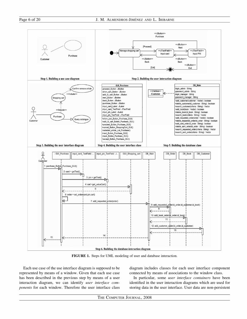
Each use case of the use interface diagram is supposed to be
represented by means of a window. Given that each use case
has been described in the previous step by means of a user
interaction diagram, we can identify user interface com-
ponents for each window. Therefore the user interface class
diagram includes classes for each user interface component
connected by means of associations to the window class.
In particular, some user interface containers have been
identified in the user interaction diagrams which are used for
storing data in the user interface. User data are non-persistent
FIGURE 1. Steps for UML modeling of user and database interaction.
Page 6 of 20 J. M. ALMENDROS-JIMENEZ AND L. IRIBARNE
THE COMPUTER JOURNAL, 2008
data or client-side data which are handled by means of the user
interface at client-side. Therefore the user interface diagram
can be seen as the client-side (class) description of the system.
Figure 1 shows a piece of the user interface class diagram
of the Customer’s side including a class for the Purchase
window.
2.5. Building database class diagrams
The fifth step consists in building a class diagram for the
database (or application) components, called database class
diagram.
From the use case diagram and user interaction diagrams,
we can identify which kind of persistent data should be
stored in our application. Persistent data are server-side data
and will be handled by user interface requesting/updating.
We will follow a specific architecture for database design—
we believe that some other proposals [39, 40] for database
design in UML can also be adopted in our framework—in
which there is a root class, usually called database main
class, which is a container of table classes, each one for a
piece of the whole database. It ensures the data distribution
and normalization, but forces that database operations are
more complex. In each table class JBDC code is supposed to
be embedded. The main class is responsible for the creation
and destruction of the table classes, and coordinates the
table accesses. Therefore, we assume that data can be
distributed; that is, table classes include each a piece of the
whole database, and they can be physically distributed.
One of the contributions of our work is the description
by means of sequence diagrams of not only the database
interactions with the user interface but also how databases
collaborate in order to supply/update the requested/sent data.
Figure 1 shows a piece of the database class diagram in
which a realization dependence between the main class (i.e.
DB_main) and an interface called ICustomer is described.
The window of the customer will be connected to this interface
to achieve the customer tasks.
2.6. Building database-interaction diagrams
The final step consists in building a set of specialized sequence
diagrams for the description of user interface and database
interactions, called database interaction diagrams.
From the user interaction diagrams, the user interface class
diagram and the database class diagram, we can build a set of
database interaction diagrams. We distinguish two kinds of
database interaction diagrams.
The first kind are those handling non-persistent data, that is,
client-side operations. In this case, database interaction dia-
grams describe how user interface components are modified
by user tasks. Typically, they describe use cases in which the
user adds or deletes elements from the containers of the user
interface. Such user tasks have been identified in the use case
diagram in the first step, later identified in the user interface
diagram and also described in the user interaction diagrams.
However, the user interaction diagram does not describe how
the corresponding containers are updated by user interactions,
and in database interaction diagrams they are described.
The second kind are those handling persistent data, that is,
server-side operations. In this case database interaction
diagrams describe how the user interface interacts with the
server, and how it requests or updates persistent data.
However, some of the steps can refer to user interface
components. Typically, the requested data from the server
become local to the client. In this case, the database class
diagram is used for collecting information about which kind
of objects (table class instances) interacts for each request.
In both cases, some of the objects can achieve tasks of
business logic which can be identified by the architect.
The proposed technique builds a database interaction
diagram for each transition consulting/updating the data con-
tainers of the system—the architect is still free to select which
data containers (user interface and database containers) are
updated or requested in each transition.
We have described our technique by means of six steps.
However, they have not to be followed necessarily in this
order, and in general the development model can be in
spiral: developing some parts of the system and some mistakes
can be found leading to a previous step. In addition, some parts
of the system can be developed in more detail before other
parts of the system have been developed.
Figure 1 shows a database interaction diagram corresponding
to the purchase process from the customer window, in which
there is an interaction with the persistent containers of the
database involving the catalog and the customer and customer
order database. In addition, the sequence diagram shows how
the task consults data from the non-persistent containers
included in the customer window (i.e. Input card, Input PIN
and GUI_Shopping_Cart).
2.7. Tool support
Our design technique involves many rules, naming conven-
tions and synchronizations between models that are
managed in the architect head. This would make the tech-
niques difficult to apply. As the techniques rely on cross
checking of names and certain conventions, they should be
supported by a tool.
Now, we would like to sketch the requirements of a tool for
supporting our design technique. These requirements can be
summarized as follows:
† Model support: Basically, the tool should allow to model
use case, state and sequence diagrams.
† UML profile: The tool should provide a library of UI
components and UML stereotypes for each UI com-
ponent, to be used in state and sequence diagrams.
UML MODELING OF USER AND DATABASE INTERACTION Page 7 of 20
THE COMPUTER JOURNAL, 2008

Such UI components should be classified according to
the following criteria:
† By behavior: input, output and input/output UI
components. In particular, UI containers should be
distinguished from non-container components.
† By similarity: some UI components are similar in beha-
vior. For instance, database items can be shown to the
architect by means of different user interface containers
of similar behavior. The tool should allow the architect
to define a hierarchical classification (i.e. more simple
and richer) of UI components. Such classification will
be useful for detecting generalization relationships
between use cases in the user interface diagram.
† UI component specification: A complete set of attributes/
operations on UI components should be available for the
architect.
† Naming conventions: A data dictionary should be
handled by the architect. It includes: use case names,
state diagram names, state names, transition names and
sequence diagram names.
† Model synchronization: The tool should help the
architect as follows:
† Each use case is named and can be annotated to be
associated to a user interface or not.
† Each use case associated to a user interface is required
to be described by means of a main user interaction
diagram. The name of the main user interaction
diagram is UI_usecase-name.
† From the specified states of a user interaction diagram,
the architect selects the states to be assigned a separate
window. The name of the separate user interaction
diagram is UI_state-name.
† From the specified states of a user interaction diagram,
the architect selects those to which a window will be
associated. The name of the window is GUI_state-
name. In particular, use cases associated to a window
have a window whose name is GUI_usecase-name.
† The tool should generate automatically a user interface
diagram in which inclusion and generalization
relationships are added according to the proposed
criteria. In particular,
† The inclusion relationship has been specified by the
architect by associating a separate window to
certain states of use cases.
† The generalization relationship is selected by the
architect according to the specified criteria.
† The tool should generate a user interface class diagram
from the user interface diagram. Naming of window
classes follows the above criteria.
† From the specified transitions of the user interaction
diagrams, the tool should request the names of the
persistent and non-persistent containers to which
such transition updates or consults. The architect
selects such non-persistent containers from the user
interaction diagrams. Persistent containers are added
as classes in a new database class diagram. The name
of the persistent container is DB_container-name.
† The tool should request a sequence diagram (i.e. a
database interaction diagram) for each transition of
the user interaction diagrams, adding as objects of
the sequence diagram the set of persistent and
non-persistent objects selected by the architect. The
architect could select which of the transitions are not
associated to a sequence diagram. The name of
the sequence diagram (i.e. a database interaction
diagram) associated to a transition is DBI_transition-
name_UID-name.
† The architect should model each sequence diagram,
and the tool should provide the available operations
for each UI component and, in addition, the tool
adds new operations from the messages to non-
persistent UI objects. In particular, for each transition
the tool should add a new operation to the window
class including such an event named UIcomponent-
name_class-name_GUI().
† The tool should update the database class diagram with
new operations for persistent containers.
† Finally, the tool could generate code from sequence
diagrams. The code is generated for each class
involved in each sequence diagram.
3. A CASE STUDY: AN INTERNET BOOK
SHOPPING (IBS) SYSTEM
In this section we will present the IBS case study in more
detail. For an extension of the example, and as a complement
to this article, the reader is referred to the following web site,
where all diagrams and the complete case study are given:
http://indalog.ual.es/mdd/udbi.
3.1. Building a use case diagram
As we have established in the proposed technique, the first step
consists in identifying those actors and main tasks (i.e. use
cases) of our future IBS application, by using a use case
diagram.
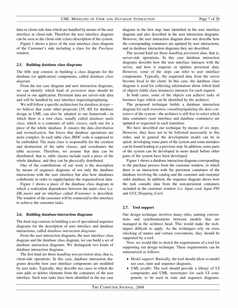
Let us suppose that the architect, who is designing the
system, identifies three actors: first, the customer who interacts
with some windows to consult and purchase by Internet,
second, the architect also identifies an Ordering Manager,
who deals (totally or partially) with pending orders sent by
the customer, and finally, an Administrator who can manage
the catalog (for instance, by adding, modifying, or removing
items), update orders (for example, by canceling orders) or
partially update orders.
Page 8 of 20 J. M. ALMENDROS-JIMENEZ AND L. IRIBARNE
THE COMPUTER JOURNAL, 2008
All these requirements are captured by the architect through
a use case diagram as shown in Fig. 2. The three actors pre-
viously mentioned (Customer, Manager and Administrator)
can be seen in the diagram, and the tasks each of them
carries out in the IBS are represented in the diagram with
use cases connected by means of associations to each actor.
We will focus on the customer tasks in the following, whose
complete analysis and design is enough to understand our
technique.
3.2. Building user interaction diagrams
Next we will describe the processes followed by the customer
to make the purchase, that is, how the user interacts with the
user interface components of the future windows of the
system.
In general, we have to model each task by means of the
UML specialized state diagrams called user interaction
diagrams.
In this kind of diagrams the states are user interface
containers of input/output interaction, for example, a text
field where the user can type a searching criterion, or an
item list where the query result from the database can be listed.
Transitions represent interactions with the user interface
components, that is, events associated to the windows or
user interface components. For example, buttons are pressed
in the windows by the user to carry out a specific task, or
items can be selected with the mouse from a list in order to
achieve a given action from them (for instance, removing or
selecting items to put them into the shopping cart).
In our proposed technique, states and transitions are
stereotyped by the name of the user interface component
they are associated with. User interface components are
taken from the Java swing package. Therefore transitions
can be labeled by means of kkJButtonll and states by
means of kkJTextFieldll, kkJListll or kkJLabelll.Some states may not be stereotyped. A non-stereotyped
state represents a user interaction diagram. In other words, a
given task can be decomposed into subtasks, and each subtask
can be described by means of a user interaction diagram.
Then the main task includes subtasks by specifying non-
stereotyped states in its user interaction diagram. The architect
can decide to make a unique user interaction diagram for each
task (i.e. use case) identified in the use case diagram or to
decompose the main processes into two or more user interaction
diagrams in order to improve/simplify the description and/or to
reuse subtasks for other tasks of the same actor or another actor.
Therefore, each use case (i.e. task) is modeled by means of one
or more user interaction diagrams.
In our case study, the purchase task is as follows. When the
customers are registered, they access a window from which
the purchase process is carried out. They can query the
catalog about the items they want to buy and then choose
from the query result those items they would like to add to
the shopping cart. Moreover, at anytime, customers can look
around for the items added to the shopping cart or eliminate
some of them. When the customers have finished to add
items into the shopping cart, they will achieve the purchase
by pressing a button and the window will require a credit
card number and the card control code (PIN) to carry out the
transaction by Internet.
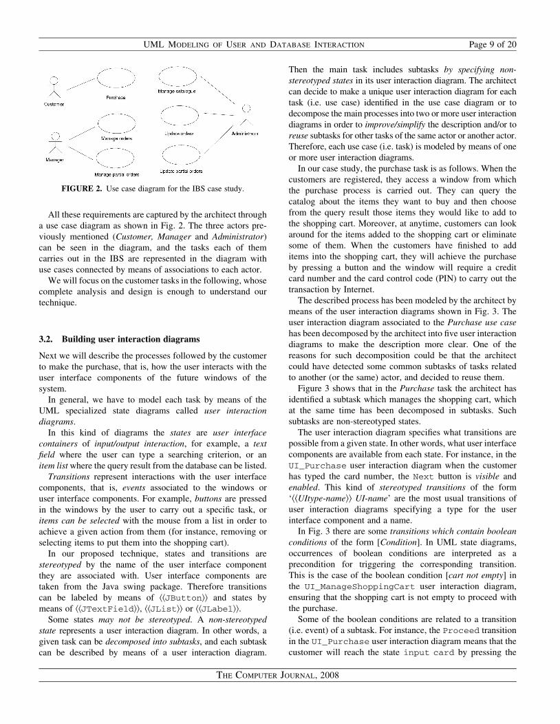
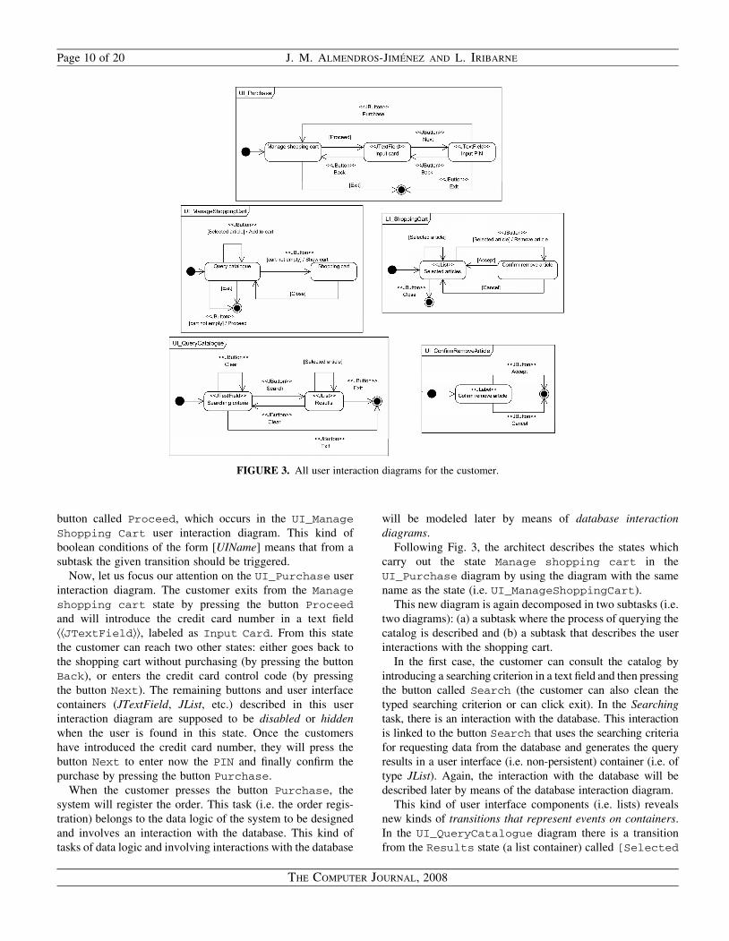
The described process has been modeled by the architect by
means of the user interaction diagrams shown in Fig. 3. The
user interaction diagram associated to the Purchase use case
has been decomposed by the architect into five user interaction
diagrams to make the description more clear. One of the
reasons for such decomposition could be that the architect
could have detected some common subtasks of tasks related
to another (or the same) actor, and decided to reuse them.
Figure 3 shows that in the Purchase task the architect has
identified a subtask which manages the shopping cart, which
at the same time has been decomposed in subtasks. Such
subtasks are non-stereotyped states.
The user interaction diagram specifies what transitions are
possible from a given state. In other words, what user interface
components are available from each state. For instance, in the
UI_Purchase user interaction diagram when the customer
has typed the card number, the Next button is visible and
enabled. This kind of stereotyped transitions of the form
‘kkUItype-namell UI-name’ are the most usual transitions of
user interaction diagrams specifying a type for the user
interface component and a name.
In Fig. 3 there are some transitions which contain boolean
conditions of the form [Condition]. In UML state diagrams,
occurrences of boolean conditions are interpreted as a
precondition for triggering the corresponding transition.
This is the case of the boolean condition [cart not empty] in
the UI_ManageShoppingCart user interaction diagram,
ensuring that the shopping cart is not empty to proceed with
the purchase.
Some of the boolean conditions are related to a transition
(i.e. event) of a subtask. For instance, the Proceed transition
in the UI_Purchase user interaction diagram means that the
customer will reach the state input card by pressing the
FIGURE 2. Use case diagram for the IBS case study.
UML MODELING OF USER AND DATABASE INTERACTION Page 9 of 20
THE COMPUTER JOURNAL, 2008
button called Proceed, which occurs in the UI_Manage
Shopping Cart user interaction diagram. This kind of
boolean conditions of the form [UIName] means that from a
subtask the given transition should be triggered.
Now, let us focus our attention on the UI_Purchase user
interaction diagram. The customer exits from the Manage
shopping cart state by pressing the button Proceed
and will introduce the credit card number in a text field
kkJTextFieldll, labeled as Input Card. From this state
the customer can reach two other states: either goes back to
the shopping cart without purchasing (by pressing the button
Back), or enters the credit card control code (by pressing
the button Next). The remaining buttons and user interface
containers (JTextField, JList, etc.) described in this user
interaction diagram are supposed to be disabled or hidden
when the user is found in this state. Once the customers
have introduced the credit card number, they will press the
button Next to enter now the PIN and finally confirm the
purchase by pressing the button Purchase.
When the customer presses the button Purchase, the
system will register the order. This task (i.e. the order regis-
tration) belongs to the data logic of the system to be designed
and involves an interaction with the database. This kind of
tasks of data logic and involving interactions with the database
will be modeled later by means of database interaction
diagrams.
Following Fig. 3, the architect describes the states which
carry out the state Manage shopping cart in the
UI_Purchase diagram by using the diagram with the same
name as the state (i.e. UI_ManageShoppingCart).
This new diagram is again decomposed in two subtasks (i.e.
two diagrams): (a) a subtask where the process of querying the
catalog is described and (b) a subtask that describes the user
interactions with the shopping cart.
In the first case, the customer can consult the catalog by
introducing a searching criterion in a text field and then pressing
the button called Search (the customer can also clean the
typed searching criterion or can click exit). In the Searching
task, there is an interaction with the database. This interaction
is linked to the button Search that uses the searching criteria
for requesting data from the database and generates the query
results in a user interface (i.e. non-persistent) container (i.e. of
type JList). Again, the interaction with the database will be
described later by means of the database interaction diagram.
This kind of user interface components (i.e. lists) reveals
new kinds of transitions that represent events on containers.
In the UI_QueryCatalogue diagram there is a transition
from the Results state (a list container) called [Selected
FIGURE 3. All user interaction diagrams for the customer.
Page 10 of 20 J. M. ALMENDROS-JIMENEZ AND L. IRIBARNE
THE COMPUTER JOURNAL, 2008
Article]. The architect specifies this kind of transitions by
modeling specific events of user interface components. In this
case, the architect has specified that the customer can select
articles from the result list. The specification of such event
is needed for specifying when the user can add items to the
shopping cart (i.e. when at least one item has been selected).
Such transitions are input user interactions but associated to
output user interface components.
Thus, the customer can (a) select items from the result list
with the mouse, or (b) press the button Clear to clean the
JList container, returning to the Searching criteria state,
or (c) cancel the process by pressing the button Exit.
Anyway, the transition [Selected article] on the
state Results of the UI_QueryCatalogue diagram
can be interrupted when the customer clicks on the button
called Add to cart, defined in the user interaction
diagram that contains the QueryCatalogue state (i.e. the
UI_ManageShoppingCart diagram). Let us remark that
in the state QueryCatalogue there is a transition of
the type [Selected article]/Add to cart whose
meaning is that whenever an element of the list has been
selected, the button Add to cart is enabled, and in such a
case, the customer can press the button (adding the selected
elements to the shopping cart, as its name suggests). There
is a subtask linked to Add to cart button which takes
the selected elements and incorporates them to the shopping
cart container. This subtask involves an interaction with
the data container for the shopping cart (i.e. a non-persistent
container). This subtask will be modeled later by means of
a database interaction diagram. This kind of subtasks
involving data containers in the user interface are modeled
in our approach by means of database interaction diagrams.
Finally, from the QueryCatalogue state the customer can
look around the shopping cart (i.e. transition Show cart) or
proceed with the purchase (i.e. transition Proceed) whenever
the cart is not empty (i.e. condition [cart not empty]).
Such a checking is linked to a data container (i.e. the shopping
cart container) and can be specified by means of a database
interaction diagram whenever the architect wants.
3.3. Building the user interface diagram
The third step of our technique consists in refining the original
use case diagram to generate the so-called user interface
diagram.
Let us remark that we have adopted the use case diagram as
starting point for our design technique; in fact, the use case
diagram of Fig. 2 retains the communicative role of use case
diagrams. However, we reinterpret and accommodate the
meaning of the use case diagram in the context of user inter-
face design; that is, each use case is associated to a window,
and inclusion and generalization relationships are interpreted
as embedding and inheritance of user interaction/user inter-
face components.
In our proposed technique the architect has now to decide
how many windows will conform the system, and to build
the user interface diagram including the set of windows for
the system. But there are some considerations to be taken
into account. First, the system windows have to be selected
from the set of user interaction diagrams, and secondly, the
user interface diagram has to express the relationships
between the windows.
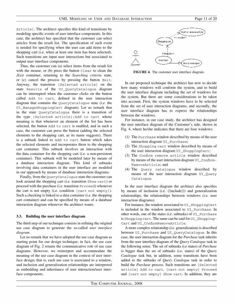
For instance, in our case study, the architect has designed
the user interface diagram of the Customer’s side, shown in
Fig. 4, where he/she indicates that there are four windows:
(1) The Purchase window described by means of the user
interaction diagram UI_Purchase;
(2) The Shopping cart window described by means of
the user interaction diagram UI_ShoppingCart;
(3) The Confirm remove article window described
by means of the user interaction diagram UI_Confirm-
RemoveArticle; and
(4) The Query catalogue window described by
means of the user interaction diagram UI_Query
Catalogue.
In the user interface diagram the architect also specifies
by means of inclusion (i.e. kkincludell) and generalization
relationships, the relationships between windows (i.e. user
interaction diagrams).
For instance, the window associated to UI_ShoppingCart
is included in the window associated to UI_Purchase. In
other words, one of the states (i.e. subtasks) of UI_Purchase
is Shopping cart. The same can be said for UI_Shopping-
Cart and UI_ConfirmRemoveArticle.
A more complex relationship (i.e. generalization) is described
between UI_Purchase and UI_QueryCatalogue. In this
case, the user interaction diagram for the Purchase task inherits
from the user interface diagram of the Query Catalogue task in
the following sense. The set of subtasks (i.e states) of Purchase
is bigger than the set of subtasks (i.e. states) of the Query
Catalogue task but, in addition, some transitions have been
added to the subtasks of Query Catalogue task in order to
build the Purchase process. Such transitions are [Selected
article] Add to cart, [cart not empty] Proceed
and [cart not empty] Show cart. In addition, they are
FIGURE 4. The customer user interface diagram.
UML MODELING OF USER AND DATABASE INTERACTION Page 11 of 20
THE COMPUTER JOURNAL, 2008

able to interrupt the Query Catalogue process. In other words,
the window for the Purchase process has been designed from
the window for the Query Catalogue process adding three
new buttons: Add to cart, Proceed and Show cart,
which trigger new processes belonging to the Purchase task.
We say in this case that Purchase is more particular than
Query Catalogue.
3.4. Building the user interface class diagram
The following step (the fourth) of our technique consists in
transforming the user interface diagram and the set of user
interaction diagrams into a specialized version of the UML
class diagram, called user interface class diagram. Basically,
the user interface class diagram (1) represents by means of
icons of classes the set of windows for our system described in
the user interface diagram, (2) adds as attributes to each
window class the set of user interface components obtained
from the set of user interaction diagrams, and (3) adds methods
to each window class for each transition/event associated to an
user interface component in the user interaction diagrams.
In Fig. 5 we show this model transformation technique for the
case study. For example, the class GUI_Purchase (class
associated with the Purchase use case) has six buttons (and
other three inherited from the class GUI_Query_catalogue).
Such buttons were specified in the user interaction diagram
UI_Purchase (and UI_QueryCatalogue). In addition,
the class GUI_Purchase contains four data containers (a
JList and three JTextfields) taken from the same user interaction
diagrams. Finally, each data container has corresponding
JLabels named as the corresponding state name in the cited
user interaction diagrams. The proposed model transformation
technique can be automatically used by a DSM tool supporting
our design technique.
However, there are some implementation details in which the
architect should help the DSM tool. For instance, some of the
classes: GUI_Query_catalogue and GUI_Shopping_
cart, include data containers like Vectors that do not
correspond to a user interface component (i.e. with the presen-
tation logic). These data containers are generally associated to
user interface containers (for instance, Vectors are associated
to JLists) in the implementation.
In addition, for each user interface component—defined as
attribute—having an associated transition/event in the user
interaction diagrams a method is added to the class. Generally
they are buttons and lists, although text fields might also have
FIGURE 5. The customer user interface class diagram.
Page 12 of 20 J. M. ALMENDROS-JIMENEZ AND L. IRIBARNE
THE COMPUTER JOURNAL, 2008
associated events. In addition, specific data containers can
have their own handler methods (for instance, the container
Vector has get and set methods).
3.5. Building the database class diagram
The following step of the proposed technique consists in
defining a class diagram for the database components, called
database class diagram. From the previous diagrams, the
architect can identify which kind of persistent data should
be considered to model the database. The interaction with
database components will be modeled later by means of the
so-called database interaction diagrams.
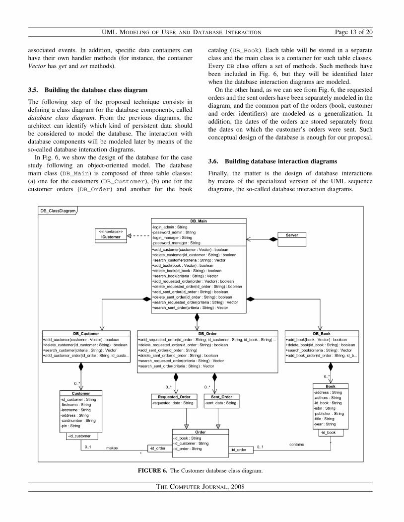
In Fig. 6, we show the design of the database for the case
study following an object-oriented model. The database
main class (DB_Main) is composed of three table classes:
(a) one for the customers (DB_Customer), (b) one for the
customer orders (DB_Order) and another for the book
catalog (DB_Book). Each table will be stored in a separate
class and the main class is a container for such table classes.
Every DB class offers a set of methods. Such methods have
been included in Fig. 6, but they will be identified later
when the database interaction diagrams are modeled.
On the other hand, as we can see from Fig. 6, the requested
orders and the sent orders have been separately modeled in the
diagram, and the common part of the orders (book, customer
and order identifiers) are modeled as a generalization. In
addition, the dates of the orders are stored separately from
the dates on which the customer’s orders were sent. Such
conceptual design of the database is enough for our proposal.
3.6. Building database interaction diagrams
Finally, the matter is the design of database interactions
by means of the specialized version of the UML sequence
diagrams, the so-called database interaction diagrams.
FIGURE 6. The Customer database class diagram.
UML MODELING OF USER AND DATABASE INTERACTION Page 13 of 20
THE COMPUTER JOURNAL, 2008
The database interaction diagrams are used as a
complement of the user interaction diagrams, although they
are also based on the other diagrams.
The criterion to be followed is to generate a database
interaction diagram for transitions/events which interact with
a data container. In our case study, transitions are associated
to JButton, JList, JTextField components and in most cases
they involve the consulting/updating of a data container (for
instance, in our case study, the transitions Selected
Articles and the Results lists, which interact with the
catalogue, order and customer databases).
As we have said, a data container can be non-persistent (for
instance, JList or JTextField in our case study) or persistent
(for instance, the catalogue, order and customer databases
in our case study). In a database interaction diagram, the
message exchange between the objects that take part in
a given task is modeled. Such tasks are triggered by
transitions/events that activate a sequence of messages to
consult/update data containers. The database interaction
diagrams can describe:
(a) only non-persistent data containers (at the user interface
side);
(b) only persistent data containers (at the database side);
(c) both kinds of containers (persistent and non-persistent
containers).
Cases of type (b) are less frequent, since generally a data-
base interaction carries out the visualization or updation of
data in some non-persistent container at the user interface side.
The architect has to take the decision on how many database
interaction diagrams have to be designed in order to comp-
lement the user interaction diagrams. In general, a given tran-
sition in the user interaction diagram can update as many data
containers as the given process requires. For instance, let us
suppose a transition associates to a button which refreshes
the data visualized by the user. In this case, the system
should update all the data containers of the user interface.
Next, we will show four cases of database interaction
diagrams, two for type (a) and two for type (c).
3.6.1. Database interaction diagrams for non-persistent
data containers
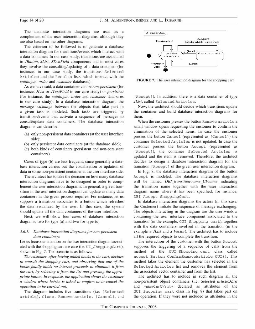
Let us focus our attention on the user interaction diagram associ-
ated with the shopping cart use case (i.e. UI_ShoppingCart),
shown in Fig. 7. The scenario is as follows:
The customer, after having added books to the cart, decides
to consult the shopping cart, and observing that one of the
books finally holds no interest proceeds to eliminate it from
the cart, by selecting it from the list and pressing the appro-
priate button. In response, the application shows the customer
a window where he/she is asked to confirm or to cancel the
operation to be carried out.
The diagram includes five transitions (i.e. [Selected
article], Close, Remove article, [Cancel], and
[Accept]). In addition, there is a data container of type
JList, called Selected Articles.
Now, the architect should decide which transitions update
the container and build database interaction diagrams for
them.
When the customer presses the button Remove article a
small window opens requesting the customer to confirm the
elimination of the selected items. In case the customer
presses the button Cancel (represented as [Cancel]) the
container Selected Articles is not updated. In case the
customer presses the button Accept (represented as
[Accept]), the container Selected Articles is
updated and the item is removed. Therefore, the architect
decides to design a database interaction diagram for the
transition [Accept] of the given user interaction diagram.
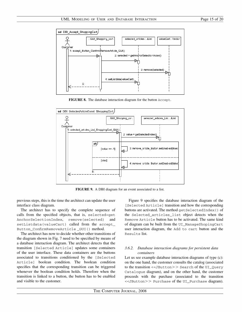
In Fig. 8, the database interaction diagram of the button
Accept is modeled. The database interaction diagrams
will be named DBI_transition-name_UI-name indicating
the transition name together with the user interaction
diagram name where it has been specified, for instance,
DBI_Accept_ShoppingCart.
In database interaction diagrams the actors (in this case,
the Customer) initiate the sequence of message exchanging.
The objects interacting in the diagram are the user window
containing the user interface component associated to the
transition (in the example, GUI_Shopping_cart), together
with the data containers involved in the transition (in the
example a JList and a Vector). The architect has to include
all the required objects to complete the transition.
The interaction of the customer with the button Accept
supposes the triggering of a sequence of calls from the
method of the GUI_Shopping_cart class called
accept_Button_ConfirmRemoveArticle_GUI(). This
method takes the element the customer has selected in the
Selected Articles list and removes the element from
the associated vector container and from the list.
The architect has to include in such diagram all the
non-persistent object containers (i.e. Selected_article:JList
and valueCart:Vector declared as attributes of the
GUI_Shopping_cart class in Fig. 8) that takes part on
the operation. If they were not included as attributes in the
FIGURE 7. The user interaction diagram for the shopping cart.
Page 14 of 20 J. M. ALMENDROS-JIMENEZ AND L. IRIBARNE
THE COMPUTER JOURNAL, 2008
previous steps, this is the time the architect can update the user
interface class diagram.
The architect has to specify the complete sequence of
calls from the specified objects, that is, selected=get
AnchorSelectionIndex, remove(selected) and
setListdata(valueCart) called from the accept_
Button_ConfirmRemoveArticle _GUI() method.
The architect has now to decide whether other transitions of
the diagram shown in Fig. 7 need to be specified by means of
a database interaction diagram. The architect detects that the
transition [Selected Article] updates some containers
of the user interface. These data containers are the buttons
associated to transitions conditioned by the [Selected
Article] boolean condition. The boolean condition
specifies that the corresponding transition can be triggered
whenever the boolean condition holds. Therefore when the
transition is linked to a button, the button has to be enabled
and visible to the customer.
Figure 9 specifies the database interaction diagram of the
[Selected Article] transition and how the corresponding
buttons are activated. The method getSelectedIndex() of
the Selected_articles_list object detects when the
Remove Article button has to be activated. The same kind
of diagram can be built from the UI_ManageShopingCart
user interaction diagram, the Add to cart button and the
Results list.
3.6.2. Database interaction diagrams for persistent data
containers
Let us see example database interaction diagrams of type (c):
on the one hand, the customer consults the catalog (associated
to the transition <<JButton.. Search of the UI_Query
Catalogue diagram), and on the other hand, the customer
proceeds with the purchase (associated to the transition
<<JButton.. Purchase of the UI_Purchase diagram).
FIGURE 8. The database interaction diagram for the button Accept.
FIGURE 9. A DBI diagram for an event associated to a list.
UML MODELING OF USER AND DATABASE INTERACTION Page 15 of 20
THE COMPUTER JOURNAL, 2008

These two scenarios are modeled by means of the diagrams of
Figs 10 and 11.
In Fig. 10 there are non-persistent containers (JTextField,
JList and Vector) and persistent containers (DB_Main and
DB_Book). The non-persistent containers have been declared
as attributes of the GUI_Query_catalogue component
(window). The methods required by the user interface
should be added to the Customer user interface class
diagram of Fig. 5 whenever they have not been added
before. The GUI_Customer class is the one that initiates
the sequence and is connected to the database through the
ICustomer interface associated to the Customer (see Fig. 6).
Here is the key point of our object-oriented modeling of
the user interface: the GUI_Customer window is connected
to the GUI_Purchase window but not to the GUI_Query_
catalogue window (see Fig. 5). However, the transition of
the Search button has been included in the user interaction
diagram associated to the GUI_Query_catalogue window
(i.e. the UI_QueryCatalogue user interaction diagram).
Therefore the method associated to the Search button has
FIGURE 11. The DBI diagram for the event associated with the Purchase button.
FIGURE 10. DBI diagram for the event associated with the Search button.
Page 16 of 20 J. M. ALMENDROS-JIMENEZ AND L. IRIBARNE
THE COMPUTER JOURNAL, 2008
been added to the GUI_Query_catalogue window class.
However, the GUI_Customer is the one connected to the data-
base and GUI_Purchase, and for this reason the object speci-
fied in Fig. 10 is GUI_Purchase instead of GUI_Query_
catalogue, but using the inherited methods. In addition, it is
consistent with the user interface diagram (see Fig. 3).
In summary, some transitions associated to user interaction
diagrams can be described by means of database interaction
diagrams in which the corresponding window objects are not
included. This is due to the inheritance relationships specified
in the user interface diagram. The architect has to take into
account the generalization relationships and the associations
specified in the user interface diagram, in order to know
which window objects participate, and which of them are
connected, in each database interaction diagram.
On the other hand, the methods offered from the database
should be added to the corresponding class in the database
class diagram whenever they have not been added before.
Now, in order to search from the catalog, the inherited
method associated to the button Search, called search_
Button_QueryCatalogue_GUI(), triggers the sequence
of calls. When the typed searching criteria is not empty the
GUI_Purchase object calls the GUI_Customer object
requesting the catalog query. The GUI_Customer object
calls by means of the ICustomer interface to the main
object of the database: DB_Main. This object is the container
of the catalog—the DB_Book object—and requests the catalog
object for the result of the query. Finally, the DB_Main object
returns to the GUI_Customer the result of the query, and
GUI_Customer updates the data container in the user interface
window.
In Fig. 11, the process followed after the customer has
pressed the Purchase button is shown. This diagram comp-
lements the UI_Purchase user interaction diagram (shown
in the Fig. 3). The architect has supposed that the customer
enters a card number and a control code in the corresponding
text fields. In addition, the method (get_valueCart)
associated to the shopping cart component requests the
content of the cart to prepare the purchase order by means
of the method call set_order(card, pin, cart),
which is split in three calls each one updating each table
class. Then, the order is added to the database by means of
the method add_requested_order(order). In this case
the window associated to the user interaction diagram is
specified in the database interaction diagram (i.e the Purchase
transition is included in the UI_Purchase user interaction
diagram, associated to the GUI_Purchase window).
The three database interaction diagrams which can also be
modeled for the case study are the following:
(a) DBI_AddToCart_Purchase: associated to the tran-
sition of the Add_to_cart button in the Purchase
window, it adds an element to the shopping cart
container;
(b) DBI_Clear_QueryCatalogue: associated to the
Clear button of the QueryCatalogue window, it
clears the searching criteria container;
(c) DBI_SelectedArticleEvent_ManageShopping
Cart: associated to the Result list in the Purchase
window, it enables and makes visible the Add to
cart button.
These diagrams do not introduce new elements w.r.t. the
proposed technique. However, the reader can find them and
the complete project in our web site: http://indalog.ual.es/
mdd/udbi.
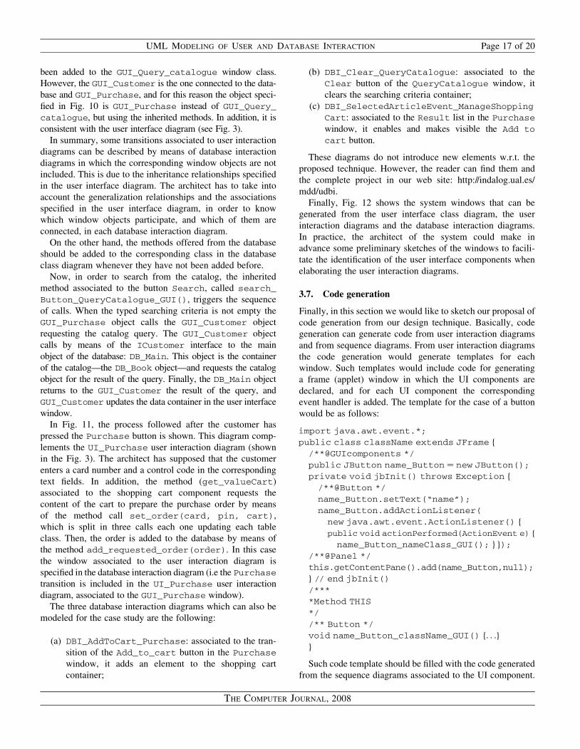
Finally, Fig. 12 shows the system windows that can be
generated from the user interface class diagram, the user
interaction diagrams and the database interaction diagrams.
In practice, the architect of the system could make in
advance some preliminary sketches of the windows to facili-
tate the identification of the user interface components when
elaborating the user interaction diagrams.
3.7. Code generation
Finally, in this section we would like to sketch our proposal of
code generation from our design technique. Basically, code
generation can generate code from user interaction diagrams
and from sequence diagrams. From user interaction diagrams
the code generation would generate templates for each
window. Such templates would include code for generating
a frame (applet) window in which the UI components are
declared, and for each UI component the corresponding
event handler is added. The template for the case of a button
would be as follows:
import java.awt.event.*;
public class className extends JFrame f
/**@GUIcomponents */
public JButton name_Button ¼ new JButton();
private void jbInit() throws Exception f
/**@Button */
name_Button.setText(“name”);
name_Button.addActionListener(
new java.awt.event.ActionListener() f
public void actionPerformed(ActionEvent e) f
name_Button_nameClass_GUI(); g g);
/**@Panel */
this.getContentPane().add(name_Button,null);
g // end jbInit()
/***
*Method THIS
*/
/** Button */
void name_Button_className_GUI() f. . .g
g
Such code template should be filled with the code generated
from the sequence diagrams associated to the UI component.
UML MODELING OF USER AND DATABASE INTERACTION Page 17 of 20
THE COMPUTER JOURNAL, 2008
For instance, in the case of DBI_Accept_ShoppingCart
sequence diagram, the generated code would be:
void accept_Button_ConfirmRemoveArticle_GUI()
f
selected ¼ selected_articles.getAnchor
Selection Index();
valueCart.remove(selected);
selected_articles.setListData(valueCart);
g
4. CONCLUSIONS AND FUTURE WORK
We have developed a technique for user and database
interaction design based on UML use case, state and sequence
diagrams. In addition, we have studied a model transformation
technique of UML models for obtaining class diagrams from
use case, state and sequence diagrams. Such modeling and
transformation techniques are focused on WIMP user interface
design (in particular, the Java swing package). Our technique
allows the description of user interactions through a user inter-
face, and describes how the user interface interacts with a
database server to accomplish user tasks. Finally, the proposed
technique is able to model the interaction with the non-
persistent containers which can be added in user interfaces.
We believe that more complex user interfaces: static user
interfaces (i.e. HTML), active user interfaces (i.e. Applet,
JavaScripts, . . .), or dynamic user interfaces (i.e. JSP, ASP,
PHP, CGIs, . . .) could be modeled following our technique,
adapting our user and database interaction diagrams, and
user interface and database class diagrams. The starting
point of such extension could be the works [10, 25–30, 34].
The second extension of our work could be the code genera-
tion. We have shown how we can design the structure and beha-
vior of the user interfaces in our proposal, obtaining class, state
and sequence diagrams describing the user interface. In addition,
we can incorporate operation signatures to each class. A deeper
study about code generation is considered as future work.
Finally, a DSM tool supporting our technique seems to be
needed for the practical application of our design technique.
We have validated our technique with the student projects
in the classroom. However, many of the tasks are handmade
for students. We believe that some of the steps could be
automatized by means of a model transformation tool like
ATL [41].
ACKNOWLEDGEMENTS
The authors would like to thank the anonymous referees for
their insightful comments and suggestions, that greatly
helped them improve the contents and readability of the paper.
FUNDING
This work has been partially supported by the EU (FEDER)
and the Spanish MEC under grants TIN2005-09207-C03-02
and TIN2007-61497.
FIGURE 12. Windows at the Customer side associated to the Purchase use case.
Page 18 of 20 J. M. ALMENDROS-JIMENEZ AND L. IRIBARNE
THE COMPUTER JOURNAL, 2008
REFERENCES
[1] DSM. (2008) http://www.dsmforum.org/. DSM Forum. Technical
Report, Domain Specific Modeling Forum.
[2] Balmelli, L., Brown, D., Cantor, M. and Mott, M. (2006)
Model-driven systems development. IBM Syst. J., 45, 569–585.
[3] Hailpern, B. and Tarr, P. (2006) Model-driven development:
The good, the bad, and the ugly. IBM Syst. J., 45, 451–461.
[4] Selic, B. (2006) UML 2: A model-driven development tool.
IBM Syst. J., 45, 607–620.
[5] Sendall, S. and Kozaczynski, W. (2003) Model transformation:
the heart and soul of model-driven software development. IEEE
Softw., 20, 42–45.
[6] OMG. (2005) Unified Modeling Language Specification,
version 2.0. Technical Report, Object Management Group.
[7] Goldberg, M. and Robson, D. (1983) Smalltalk-80: The
Language and its Implementation. Addison-Wesley.
[8] Barclay, P. J., Griffiths, T., McKirdy, J., Paton, N. W.,
Cooper, R. and Kennedy, J. (1999) The Teallach Tool: Using
Models for Flexible User Interface Design. Proc. 3rd Int.
Conf. Computer-aided Design of User Interfaces, Norwell,
MA, USA, pp. 139–157. Kluwer Academic Publishers.
[9] Pinheiro da Silva, P., Griffiths, T. and Paton, N. W. (2000)
Generating User Interface Code in a Model based user
Interface Development Environment. AVI ’00: Proc. Working
Conf. Advanced Visual Interfaces, NY, USA, pp. 155–160.
ACM Press.
[10] Conallen, J. (1999) Modelling web application architectures
with UML. Commun. ACM, 42, 63–70.
[11] Pinheiro da Silva, P. and Paton, N. W. (2003) User interface
modeling in UMLi. IEEE Softw., 20, 62–69.
[12] Almendros-Jimenez, J. M. and Iribarne, L. (2005) Describing
Use Cases with Activity Diagrams. Proc. Metainformatics
Symp. (MIS’04), Heidelberg, Germany, Lecture Notes in
Comuter Science, Vol. 3511, Springer, pp. 141–159.
[13] Almendros-Jimenez, J. M. and Iribarne, L. (2005) Designing
GUI Components for UML Use Cases. 12th IEEE Int. Conf.
Workshops on the Engineering of Computer-Based Systems
(ECBS’05), pp. 210–217. IEEE Computer Society Press.
[14] Almendros-Jimenez, J. M. and Iribarne, L. (2007) User
interaction and interface design with UML, Visual Languages
for Interactive Computing: Definitions and Formalizations,
Chapter XVI, Information Science Reference. IGI Global.
pp. 324–352.
[15] Almendros-Jimenez, J. M. and Iribarne, L. (2007) Describing
use case relationships by means of sequence diagrams. Comp.
J., 50, 116–128.
[16] Pinheiro da Silva, P. (2000) User interface declarative models
and development environments: a survey. In Palenque, P.
and Paterno, F. (eds), Interactive Systems: Design, Specification,
and Verification, Lecture Notes in Computer Science, Vol.
1946. Heidelberg, Germany, Springer, pp. 207–226.
[17] Mori, G., Paterno, F. and Santoro, C. (2002) CTTE: Support for
Developing and Analyzing Task Models for Interactive System
Design. IEEE Transactions on Software Engineering, August,
pp. 797–813.
[18] Paterno, F. (1999) Model-Based Design and Evaluation of
Interactive Applications. Springer, Heidelberg, Germany.
[19] Campos, P. F. and Nunes, N. J. (2005) A UML-based tool for
designing user interfaces. UML 2004 Satellite Activities,
Lecture Notes in Computer Science, Vol. 3297. Heidelberg,
Germany, Springer, pp. 273–276.
[20] Nunes, N. J. (2001) Object modeling for user-centered
development and user interface design: the wisdom approach.
PhD Thesis, University of Madeira.
[21] Nunes, N. J. (2003) Representing User-Interface Patterns
in UML. Proc. OOIS 2003, Heidelberg, Germany, Lecture
Notes in Computer Science, Vol. 2817, Springer, pp. 142–151.
[22] Nunes, N. J. and e Cunha, J. F. (2001) Wisdom–A UML Based
Architecture for Interactive Systems. Proc. DSV-IS 2000,
Lecture Notes in Computer Science, Vol. 1946, Springer, pp.
191–205.
[23] Pinheiro da Silva, P. (2002) Object modelling of interactive
systems: the UMLi approach. PhD Thesis, University of
Manchester.
[24] Pinheiro da Silva, P. and Paton, N. W. (2000) User interface
modelling with UML. Information Modelling and Knowledge
Bases XII, pp. 203–217. IOS Press.
[25] Bellettini, C., Marchetto, A. and Trentini, A. (2004) WebUml:
Reverse Engineering of Web Applications. Proc. 2004 ACM
Symp. Applied Computing, NY, USA, pp. 1662–1669. ACM Press.
[26] Gomez, J., Cachero, C. and Pastor, O. (2000) Extending a
Conceptual Modelling Approach to Web Application Design.
Advanced Information Systems Engineering: 12th Int. Conf.
(CAiSE 2000), Heidelberg, Germany, Lecture Notes in
Computer Science, Vol. 1789, Springer, pp. 79–93.
[27] Hennicker, R. and Koch, N. (2007) A UML-based Methodology
for Hypermedia Design. UML’2000 – The Unified Modeling
Language – Advancing the Standard, Heidelberg, Germany.
Lecture Notes in Computer Science, Vol. 1939. Springer.
[28] Koch, N., Kraus, A., Cachero, C. and Melıa, S. (2004)
Integration of business processes in Web applications models.
J. Web Eng., 3, 22–49.
[29] Larsen, G. and Conallen, J. (2002) Engineering web-based
systems with UML assets. Ann. Softw. Eng., 13, 203–230.
[30] Schwabe, D. and Rossi, G. (2000) An object oriented approach
to web-based applications design. Theor. Pract. Object Syst., 4,
207–225.
[31] Balzert, H., Hofmann, F., Kruschinski, V. and Niemann, C.
(1996) The JANUS Application Development Environment –
Generating More Than the User Interface. Proc. Computer-
Aided Design of User Interfaces, (CADUI’96), pp. 183–208.
Press Universiteries of Namur.
[32] Storrle, H. (2002) Group Exercises for the Design & Validation
of GUIs. Proc. Modellierung, Lecture Notes in Informatics,
Vol. p-12, pp. 135–146.
[33] Dolog, P. (2004) Model-Driven Navigation Design for
Semantic Web Applications with the UML-Guide. ICWE
Workshops, pp. 75–86.
UML MODELING OF USER AND DATABASE INTERACTION Page 19 of 20
THE COMPUTER JOURNAL, 2008
[34] Brambilla, M., Comai, S., Fraternali, P. and Matera, M. (2007)
Designing web applications with webML and WebRatio, Web
Engineering: Modelling and Implementing Web Applications,
pp. 221–260. Springer, Heidelberg, Germany.
[35] Makinen, E. and Systa, T. (2000) An Interactive Approach for
Synthesizing UML Statechart Diagrams from Sequence Diagrams.
Proc. 10th ACM Conf. on Object-Oriented Programming Systems,
Languages and Applications, NY, USA. ACM Press.
[36] Petriu, D. C. and Sun, Y. (2000) Consistent Behaviour
Representation in Activity and Sequence Diagrams. UML
2000 – The Unified Modeling Language. Advancing the
Standard: 3rd Int. Conf., Heidelberg, Germany, Lecture Notes
in Computer Science, Vol. 1939, Springer. pp. 369–382.
[37] Whittle, J. and Schumann, J. (2000) Generating Statechart
Designs from Scenarios. Proc. 22nd Int. Conf. Software
Engineering, pp. 314–323, NY, USA. ACM Press.
[38] Kosters, G., Six, H.-W. and Winter, M. (2001) Coupling use
cases and class models as a means for validation and
verification of requirements specifications. Require. Eng., 6,
3–17.
[39] Marcos, E., Vela, B. and Cavero, J.M. (2001) Extending UML
for Object-Relational Database Design. UML 2001 – The
Unified Modeling Language. Modeling Languages, Concepts,
and Tools: 4th Int. Conf., Heidelberg, Germany, Lecture
Notes in Computer Science, Vol. 2185, Springer, pp. 225–239.
[40] Mok, W.Y. and Paper, D.P. (2001) On Transformations from
UML Models to Object-Relational Databases. Proc. 34th
Annual Hawaii Int. Conf. System Sciences, p. 10. IEEE
Computer Society Press.
[41] Jouault, F. and Kurtev, I. (2006) On the Architectural Alignment
of ATL and QVT. SAC ’06: Proc. 2006 ACM Symp. Applied
Computing, NY, USA, pp. 1188–1195. ACM Press.
Page 20 of 20 J. M. ALMENDROS-JIMENEZ AND L. IRIBARNE
THE COMPUTER JOURNAL, 2008