Embed Size (px)
Citation preview
TSPIOX-S721SAV2-1-1EN_Leu, 2017-05-30
Technical specification
PIOX® S721SA
1
PIOX
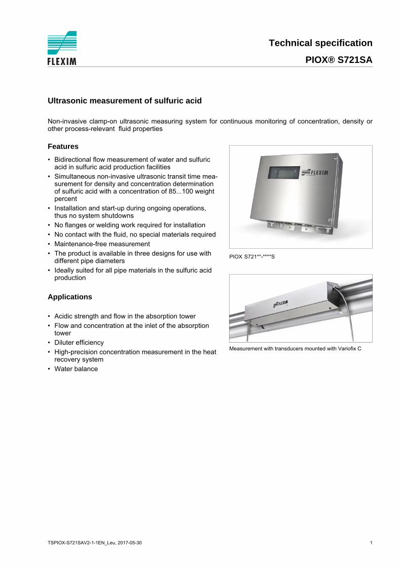
Measurement with transducers mounted with Variofix C
S721**-****S
Ultrasonic measurement of sulfuric acid
Non-invasive clamp-on ultrasonic measuring system for continuous monitoring of concentration, density orother process-relevant fluid properties
Features
• Bidirectional flow measurement of water and sulfuric acid in sulfuric acid production facilities
• Simultaneous non-invasive ultrasonic transit time mea-surement for density and concentration determination of sulfuric acid with a concentration of 85...100 weight percent
• Installation and start-up during ongoing operations, thus no system shutdowns
• No flanges or welding work required for installation
• No contact with the fluid, no special materials required
• Maintenance-free measurement
• The product is available in three designs for use with different pipe diameters
• Ideally suited for all pipe materials in the sulfuric acid production
Applications
• Acidic strength and flow in the absorption tower
• Flow and concentration at the inlet of the absorption tower
• Diluter efficiency
• High-precision concentration measurement in the heat recovery system
• Water balance

PIOX® S721SA Technical specification
Table of contents
TSPIOX-S721SAV2-1-1EN_Leu, 2017-05-302
Function ........................................................................................................................................................... 3Measurement principle...................................................................................................................................... 3Transit time measurement ................................................................................................................................ 3Transit time difference principle ........................................................................................................................ 4Number of sound paths..................................................................................................................................... 5
Transmitter ...................................................................................................................................................... 6Technical data................................................................................................................................................... 6Dimensions ....................................................................................................................................................... 72" pipe mounting kit (optional)........................................................................................................................... 8Terminal assignment......................................................................................................................................... 9
Transducers................................................................................................................................................... 10
Technical data ............................................................................................................................................... 10Transducer mounting fixture ........................................................................................................................... 11
Coupling materials for transducers ............................................................................................................ 12
Connection systems ..................................................................................................................................... 13Transducer cable ............................................................................................................................................ 13
Junction box .................................................................................................................................................. 14Technical data................................................................................................................................................. 14Dimensions ..................................................................................................................................................... 142" pipe mounting kit (optional)......................................................................................................................... 14Terminal assignment....................................................................................................................................... 15
Clamp-on temperature probe (optional) ..................................................................................................... 16
Technical specification PIOX® S721SA
TSPIOX-S721SAV2-1-1EN_Leu, 2017-05-30 3
Function
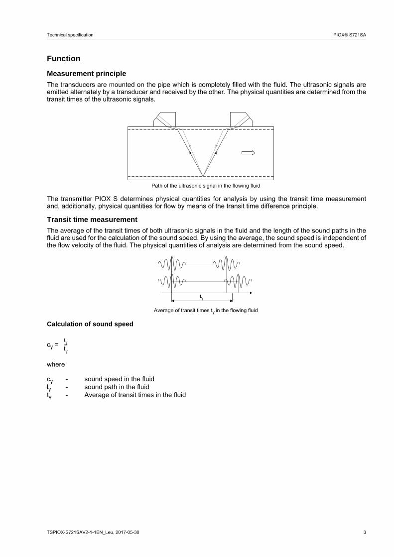
Measurement principle
The transducers are mounted on the pipe which is completely filled with the fluid. The ultrasonic signals areemitted alternately by a transducer and received by the other. The physical quantities are determined from thetransit times of the ultrasonic signals.
The transmitter PIOX S determines physical quantities for analysis by using the transit time measurementand, additionally, physical quantities for flow by means of the transit time difference principle.
Transit time measurement
The average of the transit times of both ultrasonic signals in the fluid and the length of the sound paths in thefluid are used for the calculation of the sound speed. By using the average, the sound speed is independent ofthe flow velocity of the fluid. The physical quantities of analysis are determined from the sound speed.
Calculation of sound speed
cγ =
where
Path of the ultrasonic signal in the flowing fluid
Average of transit times tγ in the flowing fluid
cγ - sound speed in the fluidlγ - sound path in the fluidtγ - Average of transit times in the fluid
tγ
lt---

4 TSPIOX-S721SAV2-1-1EN_Leu, 2017-05-30
PIOX® S721SA Technical specification
Transit time difference principle
Portable ultrasonic flow measurement of gas and liquids in hazardous areas
The transit time difference, ∆t, is measured and allows the flowmeter to determine the average flow velocityalong the propagation path of the ultrasonic signals. A flow profile correction is then performed in order to ob-tain the area averaged flow velocity, which is proportional to the volumetric flow rate.
Two integrated microprocessors control the entire measuring process. This allows the flowmeter to removedisturbance signals, and to check each received ultrasonic wave for its validity which reduces noise.
Calculation of volumetric flow rate
= kRe · A · ka ·
where
Transit time difference ∆t
- volumetric flow ratekRe - fluid mechanics calibration factorA - cross-sectional pipe areaka - acoustical calibration factor∆t - transit time differencetγ - Average of transit times in the fluid
∆tt0
V· t2 t-----------
V·

Technical specification PIOX® S721SA
TSPIOX-S721SAV2-1-1EN_Leu, 2017-05-30 5
Number of sound paths
The number of sound paths is the number of transits of the ultrasonic signal through the fluid in the pipe. De-pending on the number of sound paths, the following methods of installation exist:
• reflection arrangementThe number of sound paths is even. Both of the transducers are mounted on the same side of the pipe. Correct positioning of the transducers is easier.
• diagonal arrangementThe number of sound paths is odd. Both of the transducers are mounted on opposite sides of the pipe. In the case of a high signal attenuation by the fluid, pipe and coatings, diagonal arrangement with 1 sound path will be used.
The preferred method of installation depends on the application. While increasing the number of sound pathsincreases the accuracy of the measurement, signal attenuation increases as well. The optimum number ofsound paths for the parameters of the application will be determined automatically by the transmitter.
As the transducers can be mounted with the transducer mounting fixture in reflection arrangement or diagonalarrangement, the number of sound paths can be adjusted optimally for the application..
a - transducer distance
Reflection arrangement, number of sound paths: 2
Diagonal arrangement, number of sound paths: 3
Diagonal arrangement, number of sound paths: 1 Diagonal arrangement, number of sound paths: 1,negative transducer distance
a
a
a > 0 a < 0

6 TSPIOX-S721SAV2-1-1EN_Leu, 2017-05-30
PIOX® S721SA Technical specification
Transmitter
Technical data
PIOX S721SA /SL /SM /SSdesign field device with stainless steel housingapplication sulfuric acid measurementtransducers CDK1N52 CDM2N52
CDM2E52CDQ2N52CDQ2E52
outer pipe diameter DN200...DN2000 DN100...DN300 DN25...DN150
analysismeasurement uncertainty
- transit time (repeatable) 1/(50 . fα) ± 10-4 . t
- transit time (absolute) 1/(5 . fα) ± 10-4 . t
fα - transducer frequency, t - total transit time
e.g. for transducers with transducer frequency M (fα = 1 MHz):repeatable: 20 ns ± 10-4 . t, absolute: 200 ns ± 10-4 . t
repeatability1
- mass fraction 0.06 w%
- density 0.4 kg/m3
For the total measurement uncertainty of mass fraction and density see document TIPIOX-S_uncert_analysis_H2SO4.
fluid sulfuric acid 85...100 %
fluid temperature 0...250 °Cflowmeasurement principle transit time difference correlation principleflow velocity 0.01...25 m/srepeatability 0.15 % of reading ±0.01 m/s
accuracy2
- with standard calibration ±1.6 % of reading ±0.01 m/s- with advanced calibration
(optional)±1.2 % of reading ±0.01 m/s
- with field calibration3 ±0.5 % of reading ±0.01 m/sfluid water, sulfuric acid 0...100 %temperature compensation corresponding to the recommendations in ANSI/ASME MFC-5.1-2011transmitterpower supply 100...230 V/50...60 Hz or
20...32 V DC or11...16 V DC
power consumption < 15 Wnumber of measuring chan-nels
1
damping 0...100 s, adjustablemeasuring cycle 100...1000 Hzresponse time 1 s (1 channel)housing material stainless steel 316L (1.4404)degree of protection accord-ing to IEC/EN 60529
IP66
dimensions see dimensional drawingweight 5.1 kgfixation wall mounting, optional: 2" pipe mountingambient temperature -40...+60 °C (< -20 °C without operation of the display)display 128 x 64 dots, backlightmenu language English, German, French, Dutch, Spanish, Russian, Polish
1 for reference conditions and with field calibration2 for reference conditions and v > 0.15 m/s3 reference uncertainty < 0.2 %

Technical specification PIOX® S721SA
TSPIOX-S721SAV2-1-1EN_Leu, 2017-05-30 7
measuring functionsphysical quantities - physical quantities for analysis: concentration of analyte in matrix, concentration of matrix in analyte,
mass fraction, volume fraction, mole fraction, density, normalized density, normalized sound speed
- volumetric flow rate, flow velocity, sound speed, mass flow rate
totalizer volume, mass
diagnostic functions signal amplitude, SNR, SCNR, standard deviation of amplitudes and transit timescommunication interfaces (optional)service interfaces/diagnostic interfaces
measured value transmission, parametrization of the transmitter:- USB- Ethernet
process interfaces(max. 1 optional)
with inputs and including parametrization of the transmitter:- Modbus RTU- Modbus TCP- HART- Profibus PA- FF H1
serial data kit (optional)software FluxDiag: online diagnostics and report generation (min. Windows 7)
сable USB cabledata loggerloggable values all physical quantities, totalized values and diagnostic valuescapacity max. 800 000 measured valuesoutputs (optional)
The outputs are galvanically isolated from the transmitter.number switchable current output: 2 or switchable current output: 1, current output (HART): 1
andbinary output: 1switchable current outputAll switchable current outputs are switched to active or passive mode at the same time.
- range 4...20 mA (3.2...22 mA)- accuracy 0.04 % of reading ±3 μA- active output Rext < 350 Ω- passive output Uext = 8...30 V, depending on Rext, Rext < 1 kΩ
current output (HART)current output- range 0/4...20 mA- accuracy 0.1 % of reading ±15 μA- active output Rext < 500 Ωcurrent output I1 in HART mode- range 4...20 mA- active output Uint = 24 V
binary outputoptorelay 26 V/100 mAbinary output as alarm output- functions limit, change of flow direction or errorbinary output as pulse output mainly for totalizing- pulse value 0.01...1000 units- pulse width 1...1000 msinputs
The inputs are galvanically isolated from the transmitter.temperature input
number 1type Pt100/Pt1000connection 4-wirerange -150...+560 °Cresolution 0.01 Kaccuracy ±0.01 % of reading ±0.03 K
current inputnumber 1accuracy 0.1 % of reading ±10 μAactive input Uint = 24 V, Rint = 50 Ω, Pint < 0.5 W, not short-circuit proof- range 0...20 mApassive input Rint = 50 Ω, Pint < 0.3 W- range -20...+20 mA
PIOX S721SA /SL /SM /SS

8 TSPIOX-S721SAV2-1-1EN_Leu, 2017-05-30
PIOX® S721SA Technical specification
Dimensions
2" pipe mounting kit (optional)
PIOX S721**-****S
in mm
PIOX S721**-****S
255
240
cable gland: max. 6x M20 with flat gasket and counter nut
280
87
fixing holes for wall mounting
320

Technical specification PIOX® S721SA
TSPIOX-S721SAV2-1-1EN_Leu, 2017-05-30 9
Terminal assignment
PIOX S721
power supplyterminal strip KL4terminal connection (AC) connection (DC)PE earth earthN(-) neutral -L(+) phase +
transducersterminal strip KL11, KL12extension cable transducer cableterminal connection terminal connectionAV signal X_AV SMB connectorAVS shield X_AR SMB connectorARS shieldAR signal
outputs communication interfaceterminal strip KL9, KL10 terminal strip KL9, KL10terminal connection terminal connection communication inter-
faceP1+...P3+, P1-...P3- switchable current output A+ signal + - Modbus RTU
- Profibus PA- FF H1P1+, P1- current output (HART) B- signal -
P5a...P7a, P5b...P7b binary output S shield
USB - USBLAN - Ethernet
- Modbus TCP
analog inputsterminal strip KL7, KL8
temperature probe passive current source active current sourceterminal direct connection connection with
extension cableterminal connection of an active
inputconnection of a passive input
T1a red red T2a not connected not connectedT1A red/blue grey T2A - +T1b white/blue blue T2b + not connectedT1B white white T2B not connected -S1 shield shield S1 not connected not connected
A+B-P1+P2+P3+P4+P5aP6aP7a
S S P1-P2-P3-P4-P5bP6bP7bX2 X3
X_AV
KL11
KL12
KL7
KL8
KL9
KL10 KL4
X_AR X_BV X_BR
T1A
T1B
S1T2A
T2B
T3A
T3B
S3
T4B
T4A
T1a
T1b
S1T2a
T2b
T3a
T3b
S3
T4b
T4a
N(-)
PE L(+)
AV AVS
AGN
ARS
AR
BVBVS
BGN
BRS
BR
S721**-****Sequipotential bonding terminal
LAN USB
10 TSPIOX-S721SAV2-1-1EN_Leu, 2017-05-30
PIOX® S721SA Technical specification
Transducers
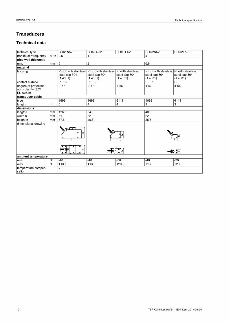
Technical data
technical type CDK1N52 CDM2N52 CDM2E52 CDQ2N52 CDQ2E52transducer frequency MHz 0.5 1 4pipe wall thicknessmin. mm 5 2 0.6materialhousing PEEK with stainless
steel cap 304 (1.4301)
PEEK with stainless steel cap 304 (1.4301)
PI with stainless steel cap 304 (1.4301)
PEEK with stainless steel cap 304 (1.4301)
PI with stainless steel cap 304 (1.4301)
contact surface PEEK PEEK PI PEEK PIdegree of protection according to IEC/EN 60529
IP67 IP67 IP56 IP67 IP56
transducer cabletype 1699 1699 6111 1699 6111length m 5 4 4 3 3dimensionslength l mm 126.5 64 40width b mm 51 32 22height h mm 67.5 40.5 25.5dimensional drawing
ambient temperaturemin. °C -40 -40 -30 -40 -30max. °C +130 +130 +200 +130 +200temperature compen-sation
x
l
hb
l
hb
hb
l

Technical specification PIOX® S721SA
TSPIOX-S721SAV2-1-1EN_Leu, 2017-05-30 11
Transducer mounting fixture
Variofix C (VC) material: stainless steel 304 (1.4301), 301 (1.4310)
inner length:VCK-*L: 500 mmVCK-*S: 350 mmVCM: 400 mmVCQ: 250 mm
dimensions:VCK-*L: 560 x 122 x 102 mmVCK-*S: 410 x 122 x 102 mm,VCM: 460 x 96 x 80 mmVCQ: 310 x 85 x 62 mm
transducer box WI for WaveInjector
see Technical specificationTSWaveInjectorVx-x
transducer box
12 TSPIOX-S721SAV2-1-1EN_Leu, 2017-05-30
PIOX® S721SA Technical specification
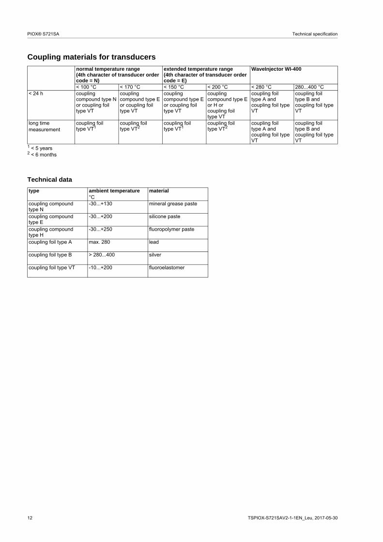
Coupling materials for transducers
Technical data
normal temperature range(4th character of transducer order code = N)
extended temperature range(4th character of transducer order code = E)
WaveInjector WI-400
< 100 °C < 170 °C < 150 °C < 200 °C < 280 °C 280...400 °C< 24 h coupling
compound type N or coupling foil type VT
coupling compound type E or coupling foil type VT
coupling compound type E or coupling foil type VT
coupling compound type E or H orcoupling foil type VT
coupling foil type A and coupling foil type VT
coupling foil type B and coupling foil type VT
long time measurement
coupling foil type VT1
coupling foil type VT2
coupling foil type VT1
coupling foil type VT2
coupling foil type A and coupling foil type VT
coupling foil type B and coupling foil type VT
1 < 5 years2 < 6 months
type ambient temperature material°C
coupling compound type N
-30...+130 mineral grease paste
coupling compound type E
-30...+200 silicone paste
coupling compound type H
-30...+250 fluoropolymer paste
coupling foil type A max. 280 lead
coupling foil type B > 280...400 silver
coupling foil type VT -10...+200 fluoroelastomer

Technical specification PIOX® S721SA
TSPIOX-S721SAV2-1-1EN_Leu, 2017-05-30 13
Connection systems
Transducer cable
Technical data
connection system TSconnection with extension cable direct connection transducers
technical type*****52
transducer frequency(3d character of transducer
order code)
F, G, H, K M, P Q S
TS
x l x l x l x lcable length m 5 ≤ 300 4 ≤ 300 3 ≤ 90 2 ≤ 40
x - transducer cable lengthl - max. length of extension cable
transducer cable extension cabletype 1699 6111 2615 5245standard length m see table above -max. length m - see table aboveambient temperature °C -55...+200 -100...+225 -30...+70 -30...+70properties halogen free
fire propagation test according to IEC 60332-1
combustion test accor-ding to IEC 60754-2
halogen free
fire propagation test according to IEC 60332-1
combustion test accor-ding to IEC 60754-2
cable jacketmaterial PTFE PFA PUR PURouter diameter mm 2.9 2.7 12 12thickness mm 0.3 0.5 2 2colour brown white black blackshield x x x xsheathmaterial stainless steel 304
(1.4301)stainless steel 304 (1.4301)
- steel wire braid with copolymer sheath
option OS: 316Ti (1.4571) option OS: 316Ti (1.4571)outer diameter mm 8 8 - 15.6
tra
nsm
itter
x
l
JB03
tran
smitt
er
x

14 TSPIOX-S721SAV2-1-1EN_Leu, 2017-05-30
PIOX® S721SA Technical specification
Junction box
Technical data
Dimensions
2" pipe mounting kit (optional)
technical type JB03dimensions see dimensional drawingweight kg 1.2 kgfixation wall mounting, optional: 2" pipe
mountingmaterialhousing stainless steel 316L (1.4404)gasket siliconedegree of protection according to IEC/EN 60529
IP67
ambient temperaturemin. °C -40max. °C +80
in mm
174
1192
wall mounting holder
70163.5
156
Ø 9
thread: 3x M20 x 1.5cable gland: max. 2x M20

Technical specification PIOX® S721SA
TSPIOX-S721SAV2-1-1EN_Leu, 2017-05-30 15
Terminal assignment
JB03
transducers
terminal connectionXV transducer , SMB connectorXR transducer , SMB connectorcable gland external shield
extension cable
terminal strip KL2terminal connectionTV signalTVS internal shieldTRS internal shieldTR signalshield terminal external shield
shield terminal
equipotential bonding terminal(at wall mounting holder)

16 TSPIOX-S721SAV2-1-1EN_Leu, 2017-05-30
PIOX® S721SA Technical specification
Clamp-on temperature probe (optional)
Technical data
technical type PT12Ndesigntype Pt100connection 4-wiremeasuring range °C -30...+250
accuracy T ±(0.15 °C + 2 . 10-3 . |T [°C]|)class A
accuracy ∆T(2x Pt matched accor-ding to EN 1434-1)
≤ 0.1 K (3 K < ∆T < 6 K), more corresponding to EN 1434-1
response time s 50housing aluminumdegree of protection according to IEC/EN 60529
IP66
weight (without con-nector)
kg 0.25
fixation clamp-onaccessoriesthermal conductivity foil 250 °C
x
dimensionslength l mm 15width b mm 15height h mm 20
connection with extension cable direct connection
extension cable
junction box
l
h

Technical specification PIOX® S721SA
TSPIOX-S721SAV2-1-1EN_Leu, 2017-05-30 17
Connection
Temperature probe
Cable
cable of temperature probe
extension cable
type 4 x 0.25 mm² black LIYCY 8 x 0.14 mm² greystandard length m 3 5/10/25max. length m - 200cable jacket PTFE PVC
Junction boxtechnical type JBT3dimensions see dimensional drawingfixation wall mounting
optional: 2" pipe mountingmaterialhousing stainless steel 316L (1.4404)gasket siliconedegree of protection according to IEC/EN 60529
IP67
cable gland max. 2x M12ambient temperaturemin. °C -40max. °C +80
Terminal assignment
JBT2, JBT3
red/blue red white/blue white
temperature probe
terminal strip KL1terminal connection
1 red2 red/blue3 white4 white/blue
extension cable
terminal strip KL2terminal connection
1 red2 grey3 white4 blue
shield terminal
equipotential bonding terminal(at wall mounting holder)

1 TSPIOX-S721SAV2-1-1EN_Leu, 2017-05-30
PIOX® S721SA Technical specification
FLEXIM GmbH
Wolfener Str. 36
12681 Berlin
Germany
Tel.: +49 (30) 93 66 76 60
Fax: +49 (30) 93 66 76 80
internet: www.flexim.com
e-mail: [email protected]
Subject to change without notification. Errors excepted.
PIOX® is a registered trademark of FLEXIM GmbH.


![Sulfuric Acid is[1]](https://img.dokumen.tips/doc/110x75/552847e14a7959c93d8b4684/sulfuric-acid-is1.jpg)

