Embed Size (px)
Citation preview
Imaging Bond Testing
A4A 2014
Dr Matt Crompton

Introduction
A4A 2014
• Use of composites and adhesively-bonded structures has increased in the
aerospace, automotive and marine industries for strength and weight saving
• The integrity of the bonds is critical for the performance of the structure and existing technologies are not suitable for most inspections
• Conventional inspection techniques can be of limited use because of the multiple glue lines and attenuative materials inherent in the lay-up.
• Bond Testing has different modes of operation to successfully inspect a wide
range of materials and combinations used in multi-layered bonded structures and modern composites

Typical Material Combinations
A4A 2014
• Bonded Structures
– Aluminum to Aluminum – Carbon to Carbon
• Monolithic Composite – Carbon – Graphite – Glass
• Sandwich Construction – Aluminum skins – Carbon skins – Glass fiber skins – Nomex, Rohacell core – Various honeycombs

Detectable Flaws
A4A 2014
• Bonded Structures
– Disbonds, unbonds, foreign objects
• Monolithic Composites – Delaminations, impact damage,
foreign objects, porosity
• Sandwich Construction – Disbonds, unbonds, impact damage,
crushed-core, foreign objects, porosity, delaminations, far-side defects
• Repair validation
DISBOND
DELAMINATION
LAMINATED STRUCTURESUBSURFACE POROSITY
LAMINATED STRUCTURE
Far-side defect

Pitch-Catch Mode
A4A 2014
• Probe consists of a transmitter
and receiver element on separate tips
• Transmitter ‘pitches’ a burst of acoustic energy that propagates into the test part. Receiver ‘catches’ the sound.
• Bonded condition- Sound waves propagate across the skin, with significant attenuation into the core
• Disbonded condition- Little attenuation into the core giving higher amplitude at receiver
Easy calibration and no couplant is required, fast, high penetration
Frequency Range = 10kHz-40kHz

Mechanical Impedance (MIA) Mode
A4A 2014
• Probe consists of driver and receiver
elements coupled in series with a single probe tip.
• The loading of receiver element, in the tip, is related to the stiffness of the test part
• When the system is ‘nulled’, the driver and receiver elements vibrate together with the same phase and amplitude
• As the receiving element moves to a disbonded area, which is weaker, the phase and amplitude of the signals change
No couplant, accurately locates defects, works on stiff, irregular & curved surfaces
Frequency Range 4kHz-30kHz

Resonance Mode
A4A 2014
Frequency Range 18kHz-370kHz
• Probe consists of an ultrasonic contact probe driven at its resonance frequency
• The instrument automatically selects the resonance frequency of the probe in air by sweeping over the frequency range and locating the phase null.
• On contact with the test part, the material damping reduces the amplitude of the signal and changes the resonant frequency. This reference condition can be nulled out. A disbond changes the acoustic impedance of the material, changing the phase and amplitude. The phase is related to depth of the defect in multi-layered structures.
• Higher frequency probes are used for better resolution and thinner parts. Thicker parts require lower frequency probes
Requires couplant, best for laminates, high penetration, can determine layer that defect resides in.

Traditional Bond Testing
• Single point measurement • Hard to understand • Not always possible to distinguish between
signal and noise • Inspector can miss defects easily • Can be slow • No digital archive Bondascope 3100
Phase Shift
Amplitude
RF mode Impedance plane Gating
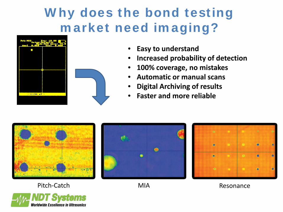
Why does the bond testing market need imaging?
• Easy to understand • Increased probability of detection • 100% coverage, no mistakes • Automatic or manual scans • Digital Archiving of results • Faster and more reliable
Pitch-Catch MIA Resonance

What is the BondHub?
• Integrated PC and scanner motor driver • Dedicated imaging and analysis software • Reads phase and amplitude output from
Bondascope (or equivalent device) • Defines scan area, speed, resolution • Plots C-scan image, with live gating/ filters • Full analysis software, 3D rendering, export
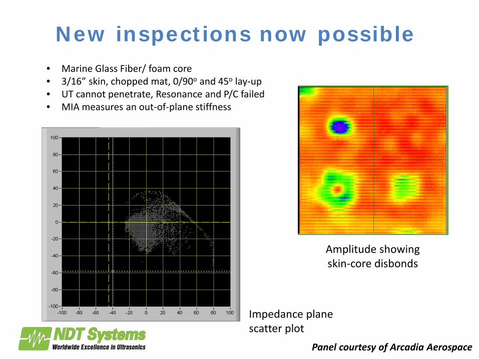
New inspections now possible • Marine Glass Fiber/ foam core • 3/16” skin, chopped mat, 0/90o and 45o lay-up • UT cannot penetrate, Resonance and P/C failed • MIA measures an out-of-plane stiffness
Amplitude showing skin-core disbonds
Impedance plane scatter plot
Panel courtesy of Arcadia Aerospace

Cracks and voids in adhesive bond line
• Bonded carbon laminates • Resonance inspection of adhesive glue line- showing
cracks and voids in the adhesive through the carbon skin.
• Vertical cracks represent a few pixel shift, not possible to detect manually
X-component- impedance plane
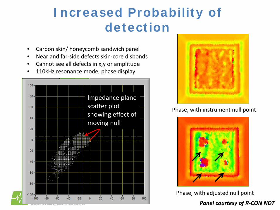
Increased Probability of detection
• Carbon skin/ honeycomb sandwich panel • Near and far-side defects skin-core disbonds • Cannot see all defects in x,y or amplitude • 110kHz resonance mode, phase display
Phase, with instrument null point
Phase, with adjusted null point
Impedance plane scatter plot showing effect of moving null
Panel courtesy of R-CON NDT

Composite Reference Standard
• Aerospace Composite laminate Reference Standard • 30 ply with brass foil, Armalon, release ply F, poly
backing material, pressure sensitive tape inserts at different depths. (BAC5578 Inserts)
• 2 plies from near surface to 2 plies from far surface • 110kHz resonance mode (compromise)
Phase display
Impedance plane scatter plot with adjusted null
Panel courtesy of Arcadia Aerospace

Composite Step block • Resonance inspection of carbon laminate step block
with inserts. • Thickness range- 0.014” – 0.070” • Both the change of thickness and defects affect
phase and amplitude
Phase display Panel courtesy of R-CON NDT

Carbon skin/ Aluminum honeycomb
• Satellite panel- a carbon skin, aluminum honeycomb • Dry coupled MIA mode • Crushed core, disbonds, far-side defects and more
Amplitude display

Mode Selection Guide
A4A 2014
Requirement Pitch-Catch Mechanical Impedance (MIA)
Resonance
Couplant required for testing No No Yes
Surface geometry Flat or curved to >1” radius
Flat or curved to <1” radius Flat or slightly curved
Typical minimum detectable flaw size >0.5” (12.7mm) >0.25” (6.4mm) >0.25” (6.4mm)
Flaw Depth determination in multi-layered bonding No No Yes
Far-side flaws or core damage on sandwich constructions Best Poor Fair
Applications
Metal to metal bonded skins (Disbonds) Fair Good Best
Multi-layer carbon laminate (Delaminations, voids, porosity) Fair Poor Best
Metal skin to metal honeycomb (Disbonds, crushed core) Good Good Good
Carbon skin to metal or Nomex honeycomb (Disbonds, delaminations crushed core)
Best Good Good
Carbon skin to foam core (Disbonds, delaminations) Best Good Fair
Multi-core sandwich structures (Inter-core disbonds, core damage) Best Poor Fair
Bonded Stiffeners (Disbonds) Good Poor Good
Glass fiber skin to foam or wood core (Disbonds, delaminations) Best Poor Good
Perforated metal skin to honeycomb core, used for acoustic liners (Disbonds) Good Good Poor
Carbon-Carbon, used for heat shields (Delaminations) Best Poor Poor
Carbon or Glass reinforced pipes or pressure vessels (Disbonds, delaminations Good Poor Poor
Carbon Overwrapped Pressure Vessels (COPV) (Disbonds, delaminations) Good Poor Poor
Composite Repair Validation (Disbonds, delaminations) Best Poor Good

Conclusions
A4A 2014
• Increased use of multi-layered bonded structures and composites leading to demand
for alternate testing method- Conventional ultrasonics has limited capability through multiple bondlines, composites with porosity and sandwich structures.
• Ultrasonic bond testing runs at a lower frequency with a range of operational modes, 2 of which are dry-coupled, that are customized for different material combinations, defect types and constructions.
• Imaging bond testing provides a powerful enhancement to conventional bond testing with C-scan imaging and analysis software providing: – a digital archive of results – an increased probability of detection – A new solution to previously ‘non-inspectable’ parts – 100% coverage with a faster and more reliable scan