Embed Size (px)
Citation preview

*Corr. Author’s Address: Jilin University, School of Mechanical and Aerospace Engineering, China, [email protected] 343
Strojniški vestnik - Journal of Mechanical Engineering 67(2021)7-8, 343-351 Received for review: 2021-03-20© 2021 Journal of Mechanical Engineering. All rights reserved. Received revised form: 2021-05-18DOI:10.5545/sv-jme.2021.7172 Original Scientific Paper Accepted for publication: 2021-06-17
Ultra-Precision Single-Point Diamond Turning of a Complex Sinusoidal Mesh Surface
Using Machining Accuracy Active Control Ning, P.X. – Zhao, J. – Ji, S.J. – Li, J.J. – Dai, H.D.
Peixing Ning1 – Ji Zhao1,2,* – Shijun Ji1 – Jingjin Li1 – Handa Dai11Jilin University, School of Mechanical and Aerospace Engineering, China
2Northeastern University, School of Mechanical Engineering and Automation, China
Single-point diamond turning (SPDT) assisted with slow tool servo (STS) is the most commonly utilized technique in the fabrication of optical modules. However, the tool path significantly affects the quality of the machined surface. In order to realize the determined machining accuracy effectively, a tool path generation (TPG) method based on machining accuracy active control (MAAC) is presented. The relationship between tool path and machining error is studied. Corner radius compensation (CRC) and the calculation of chord error and residual error are detailed. Finally, the effectiveness of the proposed approach is verified through a machining error simulation and a cutting experiment of a complex sinusoidal mesh surface fabrication.Keywords: machining accuracy active control (MAAC), machining error prediction, complex sinusoidal mesh surface, single-point diamond turning (SPDT)
Highlights• A tool path generation method based on active control machining error is proposed; the relationship between tool path
generation parameters and machining error, including chord error and residual error, is studied. • The analytical geometry method and tool contact point discretization method are used to realize tool path planning. • The presented method can predict machining error and achieve the surface accuracy control before actual processing.
0 INTRODUCTION
Single point diamond turning (SPDT) is an economical and efficient fabrication technology that can achieve an optical finish without subsequent machining [1] and [2]. At present, complex surfaces are widely used in various areas [3] and [4]. Therefore, scholars have conducted many studies on the ultra-precision machining technology of complex optical surfaces. Kong et al. [5] presented a hybrid tool servo (HTS) process and proposed a tool path generation (TPG) method. A microstructure array compound freeform surface machining experiment verified the validity of the proposed theory. Zhang et al. [6] put forward a termed toroid-surface-based slow tool servo (STS) turning method to generate discontinuously structured micro-lens arrays. Tian et al. [7] developed a novel fast tool servo system and experimented with rear-view mirrors fabrication using that system. Based on the principle of automatic dynamics analysis of mechanical systems, Khagani and Cheng [8] introduced an innovative approach for TPG. In their research, the Newton-Raphson method was used to generate the tool paths of very complex freeform surfaces; the study revealed that the time step size is very important in that method [8]. Li et al. [9] investigated a systematic approach for TPG and a theory for surface topography simulation in SPDT.
A sinusoidal grid and micro-lens array sample were machined and measured to validate the effectiveness of the proposed theoretical research. Chen et al. [10] put forward a triangle rotary method; the results of the simulations and experiments showed that the presented approach was very feasible for position-velocity-time (PVT) interpolation. The presented method can decrease the interpolation error. Wei et al. [11] set up a progressive addition lens design model and proposed an optimized TPG method for diamond turning of the optical freeform surface. Ji et al. [12] designed and machined a compound freeform surface using an optimized TPG approach. Fang et al. [13] studied a cylindrical coordinate machining method for freeform surfaces fabrication, in which a typical non-uniform rational B-spline (NURBS) was utilized to fit the feature points. They also carried out a machining experiment of a compound eye structure surface to prove the theory. The above research studies mainly focused on TPG, corner radius compensation (CRC) and machined surface topography analysis. However, few studies have been conducted on the basis of TPG to ensure machining accuracy. In this study, a TPG method based on machining accuracy active control (MAAC) is proposed, and the relationship between TPG parameters and machining error, including chord error and residual error, is studied.

Strojniški vestnik - Journal of Mechanical Engineering 67(2021)7-8, 343-351
344 Ning, P.X. – Zhao, J. – Ji, S.J. – Li, J.J. – Dai, H.D.
This paper proposed a TPG method by MAAC for complex surface SPDT assisted by STS. In Section 2, the presented method and CRC are described minutely. The relationship between tool path and machining errors is studied. An experiment for a complex sinusoidal mesh surface fabrication utilizing the proposed method is carried out in Section 3. Finally, Section 4 summarizes the paper.
1 TPG BASED ON MAAC
1.1 Machining Accuracy Active Control Method
In the process of complex mirror-like surface machining, TPG is the first and the most critical step, which has a visible impact on surface topography and surface finish of the machined workpiece. The SPDT technology is based on spindle rotary motion and linear reciprocating motion. The spindle rotation and the Z-axis reciprocating motion produce the chord error in the direction of cutting motion, and the X-axis linear motion produces the residual error in the direction of feed motion.
Considering the above two principle errors, the TPG method based on MAAC can be used as
the selection basis of cutting contact points (CCPs). Thus, the tool path for SPDT of the complex surface that meets the requirements of machining errors can be obtained. The method is generally divided into the following two steps:
Firstly, the feed f should be calculated according to the requirement of residual error. Because there is a certain interval between two adjacent circles of the tool path, and the shape of the cutting edge is a circular arc, the cutting residue will be produced in the direction of cutting motion during the machining process. To calculate the residual error, the section curve in radial direction z = f (r) should be obtained, and the curvature radius Ri at CCP Pi(ri, zi) should be calculated by Eq. (1):
RK
f rf ri
i
i
i
� ��1 1 2 3 2( ( ( )) )
( ),
/'''
(1)
where Ki is the curvature at each CCP, f '(ri) is the first derivative of the section curve, f ''(ri) is the second derivative of the section curve. According to the difference of curvature, the calculation of cutting residual height can be divided into three forms [14]; the principle is indicated in Fig. 1.
Fig. 1. Schematic diagram of residual error calculation

Strojniški vestnik - Journal of Mechanical Engineering 67(2021)7-8, 343-351
345Ultra-Precision Single-Point Diamond Turning of a Complex Sinusoidal Mesh Surface Using Machining Accuracy Active Control
When the requirement of residual error is Δres, the feed fi at CCP Pi(ri, zi) can be obtained through Eqs. (2) and (3):
f r R
fR r R
re res i
res res res res
1
2
2 2 0
2 2 2
� �� � � �
��� � � � � � �
s
i
( )
( )( )
�
� ii
res ii
res res i res res i
rR
R
fR r R
�� �� �
�
��� � � � � � � �
20
2 2 23
�
�
( )
( )( ) 220
rR
Rres i
i�� �
� ��
�
�
����
�
���� ( )
, (2)
f f f fi = min{ , , }.1 2 3 (3)
Secondly, the TPG could be completed on the basis of the requirement of chord error. In the cutting process, the tool path between two adjacent CCPs is a straight line rather than an ideal curve. The chord error is the linear error between a realistic tool path and an ideal curve, as presented in Fig. 2. The analytical mathematical optimization TPG method can be used to realize active control for chord error: The tool path can be expressed as z = f (φ). Because the distance between two adjacent CCPs is very small, the tool path between two points can be approximated as a circular arc. Therefore, the chord error Δcho ≈ δchord. According to the geometric relationship of incipient point Pj and required chord error Δcho, the next CCP Pj+1 could be derived from Eq. (4):
� � � � �cho chord j j
j jRP P
� =R 2 1 2
2( ) . (4)
Repeating the above process with Pj+1 as the initial point, the TPG can be finally achieved based on active control for chord error.
1.2 Corner Radius Compensation (CRC)
In the SPDT process, if the vertex of the cutting edge always moves along the CCPs, overcut will occur when curvature is not zero, and a large machining error will be leaded. To make the cutting edge always tangent to the section curve in the radial direction of the proposed surface in the machining process, the CRC is needed. Unlike the process of milling, the CCPs needs to be compensated in three directions of space. Since there is no Y direction motion in SPDT, the CRC only needs to consider the compensation in the XZ plane. The principle of CRC is detailed in Fig. 3.
Fig. 3. Schematic diagram of CRC
Fig. 2. Schematic diagram of chord error calculation

Strojniški vestnik - Journal of Mechanical Engineering 67(2021)7-8, 343-351
346 Ning, P.X. – Zhao, J. – Ji, S.J. – Li, J.J. – Dai, H.D.
The black line is the original position without CRC. At this point, the shaded area indicates that overcut occurred. To avoid overcut and keep the cutting point position constant, the trajectory of the CCPs Pi(ri, zi) offsets a length of corner radius along the normal vector direction nri and the CLPs Pi(ri, zi) is obtained, as written in Eq. (5):
r r rf r
f r
z z rf r
i ii
i
i ii
''
''
'''
� ��
� ��
�
�
��
�
��
�
�
( )
( )
( )
.1
1
1
2
2
(5)
Fig. 4. Form chart of complex sinusoidal mesh surface machining
2 MACHINING EXPERIMENT AND DISCUSSION
To prove the feasibility of the proposed method, a machining experiment of a complex sinusoidal mesh surface is conducted. Fig. 4 presents the flowchart of SPDT process for the surface machining.
2.1 Complex Sinusoidal Mesh Surface Model Establishing
The designed complex sinusoidal mesh surface is combined with umbrella surface and radial sinusoidal
surface with a gradual amplitude gradient. Therefore, the mathematical model can be established as Eq. (6):
Z � � ����
��� �
�
��
�
��
� � ���
���
hRr
Rl
hRr
hRr
w
w
w
w
1 1
2
2
2
2
sin
sin
��
�
��� ��
�
��
�
��
hRr
w
2 , (6)
where hRr
Rl
hRr
w
w
w
1 12
2� ��
��
��� �
�
��
�
��sin
��
� expresses

Strojniški vestnik - Journal of Mechanical Engineering 67(2021)7-8, 343-351
347Ultra-Precision Single-Point Diamond Turning of a Complex Sinusoidal Mesh Surface Using Machining Accuracy Active Control
umbrella surface and hRr h
Rr
w w
2 22� �
��
��� �
�
��
�
��sin
���
indicates complex radial sinusoidal surface; h1 and h2 are amplitudes of the two surfaces; l and ω are the number of sinusoids with complete periods in circumferential and radial directions, respectively; r is polar radius, Rw is radius of the workpiece, φ is polar angle.2.2 TPG and Machining Error Prediction
The designed complex sinusoidal mesh surface is modelled as Eq. (10) with the maximum amplitude hmax = 0.2 mmm, h1 = h2 = hmax/4, the number of sinusoids with complete periods in a circumferential direction is l = 8, the number of sinusoids with complete periods in radius direction is ω = 32/15, the radius of workpiece Rw = 8 mm, as shown in Fig. 5. The Δres is set as 0.5 μm and Δcho is also set as 0.5 μm. The TPG method based on MAAC is used for tool path planning of the designed surface. Fig. 6 presents the planning result.
Fig. 5. Complex sinusoidal mesh surface model
Fig. 6. Tool path planning of complex sinusoidal mesh surface machining
Reversing the calculation process of TPG applied above, the prediction of machining errors can be realized. The prediction consequence indicated that
the errors are all maintained within 0.5 μm as shown in Fig. 7.
a)
b) Fig. 7. Machining error prediction; a) chord error prediction,
and b) residual error prediction
The CLPs after CRC, which can be directly applied to computerized numerical control (CNC) machine for complex sinusoidal mesh surface fabrication, is depicted in Fig. 8:
Fig. 8. CLPs and CCPs trajectory of complex sinusoidal mesh surface machining
2.3 Machining and Measurement Experiments
The processing experiment is conducted by using a Nanoform 250SPDT machine. The workpiece is made of Al6061. The cutting parameters are summarized in Table 1. The machine tool system and successfully machined sample are exhibited in Fig. 9.

Strojniški vestnik - Journal of Mechanical Engineering 67(2021)7-8, 343-351
348 Ning, P.X. – Zhao, J. – Ji, S.J. – Li, J.J. – Dai, H.D.
Table 1. Cutting parameters
Parameters Value
Tool rake angle γ 0°
Tool clearance angle α 10°Tool included angle ε 120°
Corner radius rε 0.496 mm
Depth of cut ap 5 μm
Feed f 0.0402 mm
Average cutting speed vc 166.72 mm/min
a)
b) Fig. 9. The machining experiment; a) machine tool system,
and b) the machined complex sinusoidal mesh surface sample
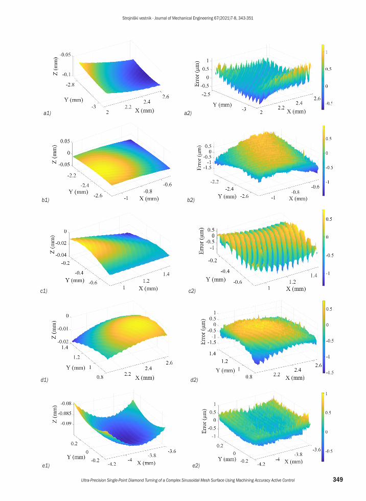
To verify the machining quality, the machined surface is measured using a newview 9000 white light interferometer profiler Zygo, as shown in Fig. 10. The measurement conditions are as follows: the enlargement factor of zoom lens was set as 1.0× (standard). The enlargement factor of the objective lens was set as 50×. The filter tray was set as Standard F1, which can be used for most surfaces measurement. The bandwidth of the filter tray Standard F1 is 125 nm, and the centre wavelength is 550 nm. The field of view in object-space was set as 0.87 mm × 0.87 mm. The measurement adopts the method of distributing points at equal distances. The number of distributing points in the X and Y directions are all 1000. Due to the limitation of the measurement vision field, eight areas on different radii of the machined surface were randomly selected for measurement,
including peak areas, valley areas and interim areas. The measurement results and the obtained machining errors are presented in Fig. 11. Figs. 11 (a1) to (h1) are reconstructed surfaces using the measurement data, and Figs. 11 (a2) to (h2) are machining errors after removing the form component of the machined surface from the original measurement data. Because the residual error and the chord error are coupled, which is inconvenient to measure and analyse separately, the machining quality can be evaluated through the peak valley (PV) value of the machined surface. PV represents the maximum peak-valley deviation of the form error of the machined surface. The residual error and the chord error could be negative. So the predicted PV can be calculated through Eq. (7):
PV m� � � � � �� �� �( ) ( ) .res cho res cho 2 � (7)
From Fig. 11, excluding the random error, the overall deviation (actual PV) of the machined complex sinusoidal mesh surface is about 2.459 μm, which is a little bit larger than the predetermined PV 2 μm, because there are some other uncontrollable factors such as measurement error, machine tool error, tool wear and cutting temperature. Therefore, it also can be demonstrated from the experiment result that the TPG by MAAC is usable.
3 CONCLUSIONS
In this paper, a TPG method based on MAAC is presented by studying the mapping relationship between tool path and processing errors. The simulation and experiment of a complex sinusoidal mesh surface machining attest to the validity of the method. The conclusions are drawn as follows:1. According to the requisition of residual error and
chord error, the tool path that meets the machining
Fig. 10. The measurement experiment
Strojniški vestnik - Journal of Mechanical Engineering 67(2021)7-8, 343-351
349Ultra-Precision Single-Point Diamond Turning of a Complex Sinusoidal Mesh Surface Using Machining Accuracy Active Control
a1) a2)
b1) b2)
c1) c2)
d1) d2)
e1) e2)

Strojniški vestnik - Journal of Mechanical Engineering 67(2021)7-8, 343-351
350 Ning, P.X. – Zhao, J. – Ji, S.J. – Li, J.J. – Dai, H.D.
4 ACKNOWLEDGEMENTS
This work is supported by Key R&D Projects of the Ministry of Science and Technology of China (Grant Nos. 2017YFA0701200 and 2018YFB1107600) National Natural Science Foundation of China (Grant No 51775237), Graduate Innovation Fund of Jilin University (Grant No. 101832020CX122).
5 REFERENCES
[1] Zhang, S.J., Zhou, Y.P., Zhang, H.J., Xiong, Z.W., To, S. (2019). Advances in ultra-precision machining of micro-structured functional surfaces and their typical applications. International Journal of Machine Tools and Manufacture, vol. 142, p. 16-41, DOI:10.1016/j.ijmachtools.2019.04.009.
[2] He, C.L., Zong, W.J., Xue, C.X., Sun, T. (2018). An accurate 3D surface topography model for single-point diamond turning.
accuracy demand can be derived by reverse application of the error calculation process.
2. Using the proposed method, the TPG and CRC for a complex sinusoidal mesh surface machining are carried out systematically. The machining error simulation manifests that the generated tool path can meet the machining accuracy requirement.
3. Machining and measurement experiment results show that the PV of the machined complex sinusoidal mesh surface is not significantly different from the predetermined PV, which attest to the effectiveness of the TPG method by MAAC.
f1) f2)
g1) g2)
h1) h2) Fig. 11. Measurement results and machining errors; (a1 to h1) reconstructed surfaces, and (a2 to h2) machining errors
Strojniški vestnik - Journal of Mechanical Engineering 67(2021)7-8, 343-351
351Ultra-Precision Single-Point Diamond Turning of a Complex Sinusoidal Mesh Surface Using Machining Accuracy Active Control
International Journal of Machine Tools and Manufacture, vol. 134, p. 42-68, DOI:10.1016/j.ijmachtools.2018.07.004.
[3] Cai, H.B., Shi, G.Q. (2019). Tool path generation for multi-degree-of-freedom fast tool servo diamond turning of optical freeform surfaces. Experimental Techniques, vol. 43, p. 561-569, DOI:10.1007/s40799-019-00307-1.
[4] Fountas, N.A., Vaxevanidis, N., V., Stergiou, C.I., Benhadj-Djilali, R. (2019). Globally optimal tool paths for sculptured surfaces with emphasis to machining error and cutting posture smoothness. International Journal of Production Research, vol. 57, p. 5478-5498, DOI:10.1080/00207543.2018.1530468.
[5] Kong, L.B., Ma, Y.G., Ren, M.J., Xu, M., Cheung, C.F. (2019). Generation and characterization of ultra-precision compound freeform surfaces. Science Progress, vol. 103, no. 1, DOI:10.1177/0036850419880112.
[6] Zhang, L., Naples, N.J., Zhou W.C., Yi, A.Y. (2019). Fabrication of infrared hexagonal microlens array by novel diamond turning method and precision glass molding. Journal of Micromechanics and Microengineering, vol. 29, no. 6, DOI:10.1088/1361-6439/ab10ff.
[7] Tian, F.J., Yin, Z.Q., Li, S.Y. (2015). Fast tool servo diamond turning of optical freeform surfaces for rear-view mirrors. International Journal of Advanced Manufacturing Technology, vol. 80, p. 1759-1765, DOI:10.1007/s00170-015-7152-9.
[8] Khaghani, A., Cheng, K. (2019). Investigation on multi-body dynamics based approach to the tool path generation for ultraprecision machining of freeform surfaces. Proceedings
of the Institution of Mechanical Engineers Part B-Journal of Engineering Manufacture, vol. 234, no. 3, p. 571-583, DOI:10.1177/0954405419863961.
[9] Li, D., Qiao Z., Walton, K., Liu, Y., Xue, J.D., Wang, B., Jinag, X. (2018). Theoretical and experimental investigation of surface topography generation in slow tool servo ultra- precision machining of freeform surfaces. Materials, vol. 11, no. 12, DOI:10.3390/ma11122566.
[10] Chen, X., Kang, M., Wang, X.S., Hassan, M., Yang, J. (2017). Tool path optimal design for slow tool servo turning of complex optical surface. Proceedings of the Institution of Mechanical Engineers Part B: Journal of Engineering Manufacture, vol. 231, no. 5, p. 825-837, DOI:10.1177/0954405416654192.
[11] Wei, Y., Zhai, P., Chen, X.Y., He, L. (2020). Study on design and diamond turning of optical freeformsurface for progressive addition lenses. Mathematical Problems in Engineering, vol. 2020, art. ID 2850606, DOI:10.1155/2020/2850606.
[12] Ji, S.J., Li, J.F., Zhao, J., Feng, M., Sun, C.R, Dai, H.D. (2018). Ultra-precision machining of a compound sinusoidal grid surface based on slow tool servo. Materials, vol. 11, no. 6, art. ID 1001, DOI:10.3390/ma11061001.
[13] Fang, F.Z., Zhang, X.D., Hu, X.T. (2008). Cylindrical coordinate machining of optical freeform surfaces. Optics Express, vol. 16, no. 10, p. 7323-7329, DOI:10.1364/OE.16.007323.
[14] Lin, R.S., Koren, Y. (1996). efficient tool-path planning for machining freeform surfaces. Journal of Engineering for Industry, vol. 118, no. 1, p. 20-28, DOI:10.1115/1.2803642.