Embed Size (px)
Citation preview

ORIGINAL ARTICLE
Study on tool wear characteristics in diamond turningof reaction-bonded silicon carbide
Zhiyu Zhang & Jiwang Yan & Tsunemoto Kuriyagawa
Received: 24 March 2010 /Accepted: 21 March 2011 /Published online: 13 April 2011# Springer-Verlag London Limited 2011
Abstract Tool wear is one of the most critical problemsin machining hard, brittle materials. In the present work,diamond turning experiments were performed onreaction-bonded silicon carbide, and the tool wearcharacteristics were investigated. A special kind of wearpattern, namely periodical groove wear, was identified onthe flank face of the tool, where the periodicity of themicrogrooves was the same as the tool feed. Geometricalanalysis showed that the periodical groove wear wascaused by the tool feed marks on the machined surface.Laser micro-Raman spectroscopy indicated that the high-pressure abrasive wear at the tool–workpiece interfacedominates the wear behavior, rather than the diamond–graphite transformation. By swinging the tool around itscurvature center during the cutting process, the periodicalgroove wear pattern was suppressed, and the tool wearwas reduced significantly.
Keywords Silicon carbide . SiC . Hard, brittle material .
Ductile machining . Diamond tool . Tool wear .
Microgroove . Tool swinging . Laser Raman spectroscopy
1 Introduction
Silicon carbide (SiC) is an important material that hasbeen extensively used in various harsh environmentalconditions, such as high temperature, high pressure, andsevere corrosion. Recently, in the optical manufacturing
industry, reaction-bonded SiC (RB-SiC) is being used asmold material for high-precision hot pressing of glasslenses, for its high-temperature hardness, thermal shockresistance, and chemical stability [1]. On the other hand,RB-SiC has very poor machinability in ultraprecisionmachining. Conventionally, it has been machined byabrasive machining processes, such as grinding, lapping,and polishing [2–5]. Abrasive machining methods arecapable of producing a fine surface finish, but it is verydifficult to precisely fabricate microstructures [6] orcomplicated shapes which are increasingly demanded inindustry. Other methods, such as laser ablation andfocused ion beam milling, could be used to generatemicrostructures, but the material removal rate and finishedsurface quality cannot meet the requirements in opticalapplications [7, 8].
As an alternative approach, the ultraprecision diamondturning technology might be usable in fabricating micro-structures and curved surface on RB-SiC. In a previouspaper, we reported the material removal mechanisms indiamond turning of RB-SiC [9] and found that althoughRB-SiC is a typical hard, brittle material, it could beprecisely machined in a ductile manner. Ductile machiningof single-crystal SiC has been reported too [10]. However,diamond tools wore severely in the diamond turningprocess, which greatly degraded the finish surface qualityas well as the form accuracy of the workpiece. Tool wearhas become a major impediment to the industrial applica-tion of diamond turning of RB-SiC.
In this study, diamond turning tests on RB-SiC wereperformed, and fundamental tool wear characteristics wereinvestigated. Tool wear patterns and their formationmechanisms were clarified, and possible techniques tosuppress the tool wear and improve the service life ofdiamond tools were proposed.
Z. Zhang : J. Yan (*) : T. KuriyagawaDepartment of Nanomechanics, Tohoku University,Aramaki Aoba 6-6-01, Aoba-ku,Sendai 980–8579, Japane-mail: [email protected]
Int J Adv Manuf Technol (2011) 57:117–125DOI 10.1007/s00170-011-3289-3

2 Experimental details
2.1 Machine tool
Diamond turning experiments were carried out on a three-axis numerically controlled ultraprecision lathe, Nachi-ASP15, the main section of which is shown in Fig. 1. Themachine tool has a hydrostatic bearing spindle and twoperpendicular hydrostatic tables along the X-axis and the Z-axis. The B-axis rotary table is built into the X-axis table.After a renovation service of the numerical control system,the resolution of the X- and Z-axes was upgraded from 10to 1 nm, and that of B-axis from 1/1,000° to 1/100,000°.
Before machining, the sample was bonded onto a copperblank using heat-softened wax, and then the blank wasvacuum-chucked onto an air-bearing spindle. Thus, thesample was rotated with the spindle and moved along the Z-axis direction. A tool holder with a three-dimensionallyadjustable mechanism was set on the rotary B-axis table.Diamond cutting tools were set onto the tool holder; thus, thetool can be moved along the X-axis direction and alsorotated/swung around the B-axis. A CCD camera wasequipped above the diamond tool to observe and adjust theposition of the cutting point.
2.2 RB-SiC samples
RB-SiC samples used in the experiments were provided byJapan Fine Ceramics Co., Ltd. The samples were produced byinfiltrating silicon melt into a green compact consisting ofcarbon powder and SiC particles with an average size of lessthan 1 μm. The liquid silicon reacts with carbon powders,forming new SiC particles. The infiltrated silicon does notreact with carbon completely, and excessive silicon fills theremaining pores in the body so that a dense RB-SiC compositeis produced [11]. The as-received samples were of cylindricalshape with polished end faces. The material properties of thesamples are tabulated in Table 1. Figure 2 shows a scanningelectron microscope (SEM) micrograph of the fast atom
beam (FAB)-etched sample surface. The smooth regionscorrespond to SiC grains, and the micropits correspond toresidual silicon. It can be seen that most of the SiC grains aredirectly bonded to each other without the presence of siliconat the grain boundaries.
2.3 Diamond cutting tools
Round-nosed cutting tools made of natural single-crystaldiamond were used in experiments. Figure 3a presentsthe schematic diagram of the diamond tool. The tool has anose radius of 10 mm, an edge length of 4 mm, a −20°rake angle (α=−20°) and a 10° relief angle (γ=10°). Asindicated in Fig. 3a, the crystallographic plane of the topsurface of the tool is {110}, and the plane indicated byline MN, which is perpendicular to the top surface andpassing the tool tip, is also {110}. Accordingly, the toolrake face is oriented close to the {210} plane. The toolflank face is curved; thus, its crystallographic planechanges with the position on the cutting edge. Two toolswith the same shape and crystal orientation of thediamond, labeled as tool #1 and tool #2, respectively,were used. Before machining, the cutting edge wasexamined by SEM. Figure 3b shows an SEM micrographof the fresh cutting edge, which is extremely sharp withoutvisible defects even at a magnification of ×10,000.
CCD cameraTool holder
Z
Y
B
Diamond tool
X
Workpiece
Fig. 1 Photograph of the experimental setup
Table 1 Material property of RB-SiC
Property items Value
Si/SiC volume ratio (%:%) 12:88
Density ρ (g/mm3) 3.12
Young modulus E (GPa) 407
Bending strength RT (MPa) 780
Thermal expansion coefficient (10−6/K) 3.23
Thermal conductivity (W/m K) 143
Porosity <0.1%
Micropits
SiC grains
Fig. 2 SEM micrograph of an FAB surface-etched RB-SiC sample
118 Int J Adv Manuf Technol (2011) 57:117–125

It should be pointed out that natural diamond has the N, O,Co, Fe, and Ni elements inside its crystal, which leads to adifferent tool wear performance from that of a single-crystaldiamond prepared by chemical vapor deposition. The diamondwear rate is also significantly different by crystallographicplanes. The tools used in the present study have curved flankfaces; thus, the crystallographic planes vary along the cuttingedges, leading to different wear rates. The effects of chemicalcomposition and crystallographic orientation of diamond ontool wear characteristics will be investigated in the future.
2.4 Cutting conditions
Face turning was carried out on the end faces of the samples.Two kinds of cutting tests were performed. One is theconventional cutting method without tool swinging, as shownin Fig. 4a. The other is the tool-swinging cutting method asshown in Fig. 4b. In the latter, the curvature center of thediamond tool is adjusted to agree with the center of the B-axis table, and the tool is swung around the B-axis center
during cutting. In this way, the cutting point is alwayschanging along the cutting edge; thus, the temperature rise ofthe cutting edge can be reduced. The experimental conditionsare listed in Table 2. The tools were examined aftermachining for a certain cutting distance (the total length ofthe cutting trace on the workpiece surface). Two levels ofcutting distance (20 m and 136 m) were used to investigatethe tool wear characteristics at the early stage and the latestage of a cut, respectively. In face turning, the cutting speedchanges in a range of 94–19 m/min.
2.5 Surface characterization
In order to confirm if there are microstructural changes in thediamond tools after machining, the flank wear land of the toolwas firstly examined using a laser micro-Raman spectroscope,NRS-3100, produced by JASCO Corporation (Tokyo, Japan).The wavelength of the laser was 532 nm, and the output laserpower was set to 13 mW. The exposure time was set to 20 s,and the spot size of the laser beam was about 1 μm. After that,
(a)
(b)
Flank face
Cutting edgeR=10 mm Rake face
A
A
=–20°
=10°
A-ARake face
Flank face
Top face (110)
(110)
M
N
α
γ
Rake face
Flank face
Cutting edge
Fig. 3 A round-nosed diamondcutting tool. a schematicdiagram of the tool and b SEMmicrograph of the cutting edge
(a)
Feeding direction
Machined surface
Unmachined surface
Workpiece
(b)
Swinging motion
Feeding direction
Machined surface
Workpiece
Unmachined surface
Swinging motion
Feeding direction
Machined surface
Workpiece
Unmachined surface
Fig. 4 Schematic models for aconventional cutting methodwithout tool swinging and btool-swinging cutting method
Int J Adv Manuf Technol (2011) 57:117–125 119

the diamond tools were Au–Pd coated for 30 s, and the flankwear land was examined using the SEM.
3 Experimental results
3.1 Tool wear pattern
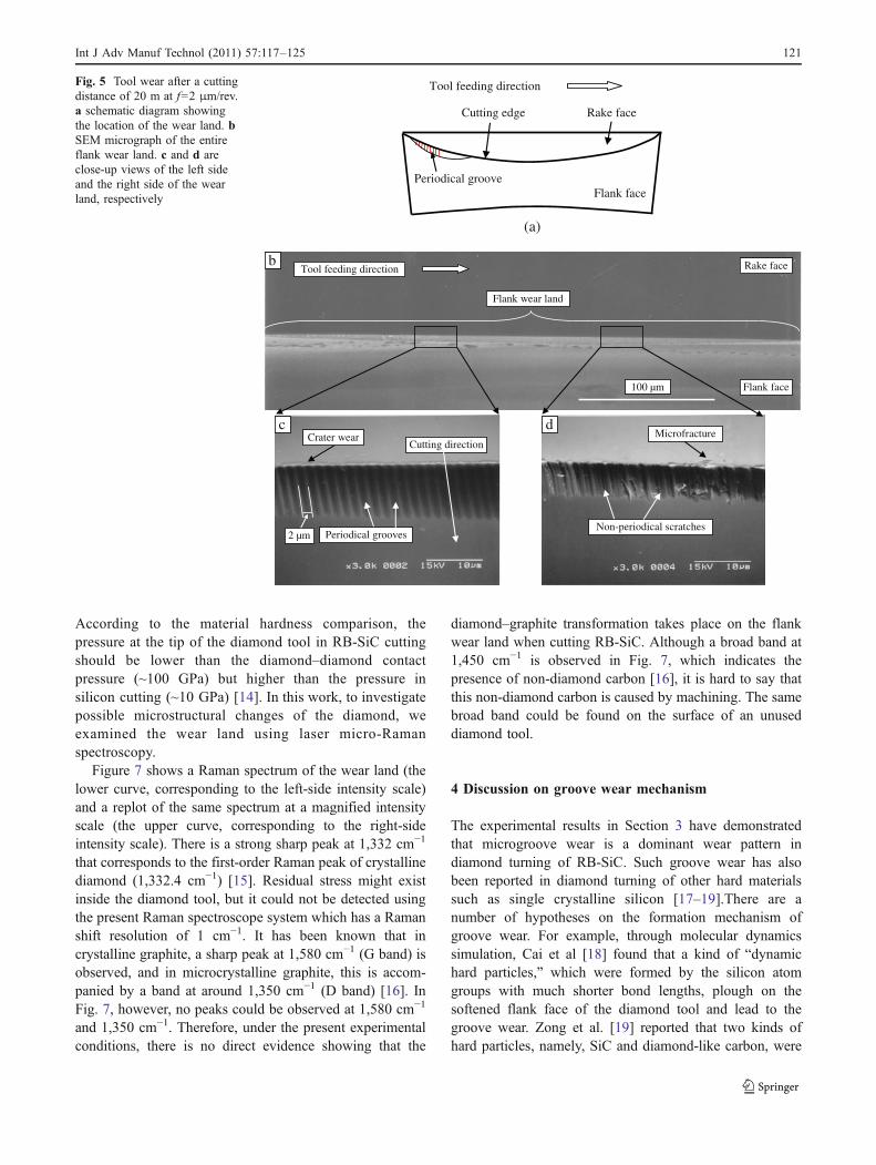
Firstly, diamond tool #1 was used for machining with theleft side of the tool contacting against the workpiece. Aftermachining for a cutting distance of 20 m at f=2 μm/rev, awear land as schematically shown in Fig. 5a was formed onthe tool. Figure 5b shows an SEM micrograph of the wearland. The tool feed direction is from left to right in thefigure. In Fig. 5b, we can see that the flank wear land islong and narrow, the maximum width of which isapproximately 10 μm. At this magnification, the wear landsurface looks uniform and nearly symmetrical about thetool tip. However, after a higher-magnification observation,it was found that the wear patterns on the left weredistinctly different from those on the right. Figure 5c is amagnified view of the left side of the wear land. Extremelyfine microgrooves, which are uniform in pitch and depth,can be observed on the wear land. This kind of wear patternis defined as “periodical groove wear” in this paper. Theorientation of the microgrooves is consistent with thecutting direction. It should be noted that due to the use ofa negative rake angle, the rake face has been slanted; thus,the cutting direction is not perpendicular to the cuttingedge, as shown in Fig. 5a. In Fig. 5c, it is also noticeablethat the pitch of the microgrooves is 2 μm, the same as thetool feed per revolution of the workpiece. Besides theperiodical groove wear, an extremely small crater wear(width ~1 μm) is also observed on the rake face. Fig. 5dshows a magnified SEM image of the right side of the flankwear land. Many scratched marks can be observed on thewear land, the orientation of which generally agrees withthat of the microgrooves in Fig. 5c. However, the scratchedmarks in Fig. 5d do not show periodicity in pitch and
uniformity in depth, and the surfaces of the scratched marksare very rough. In contrast to the small crater wear inFig. 5c, microchippings (size, ~2 μm) are observed on therake face in Fig. 5d.
Next, diamond tool #2 was used for cutting. To comparewith the results of tool #1, for tool #2, the tool feedingdirection was from right to left. After cutting for a distanceof 136 m at f=5 μm/rev, the tool was taken off forobservation. Figure 6a shows schematically the location ofthe wear land. Figure 6b is an SEM micrograph of the flankwear land. The wear land is distinctly wider than that inFig. 5b, and the shape of the wear land looks like acrescent. Figures 6c, d, and e are magnified views of threedifferent locations as indicated in Fig. 6b. As shown inFig. 6c, the left side of the wear land is very flat andsmooth. This result is distinctly different from that inFig. 5d, although both of the two sections contact with theshoulder region of the workpiece, namely the regionbetween the machined surface and the unmachined surface.The reason of this difference will be discussed later inSection 4.
At the right side of the flank wear land, as shown inFig. 6e, periodical microgrooves are observed. The groovesare uniform in pitch and depth, and the groove surfaces arevery smooth. The orientation of the grooves is the same asthe cutting direction, similar to that in Fig. 5c. However,different from Fig. 5c, the pitch between the grooves inFig. 6e is 5 μm, equal to the tool feed per revolution ofworkpiece in this case. Figure 6d shows a boundary regionbetween the smooth region and the grooved region.
3.2 Raman spectroscopy
The wear mechanism of a diamond tool is very complicatedwhich might involve chemical, physical, electrical, andmechanical interactions between diamond and workpiecematerials [12]. Also, diamond is known to undergographitization when it is subjected to high contact pressure(~100 GPa) in diamond–diamond indentation tests [13].
No tool swinging Tool swinging
Tool #1 Tool #2 Tool #2
Feed rate f (μm/rev) 2 5 5
Maximum undeformed chip thickness t (nm) 40 100 100
Cutting distance l (m) 20 136 136
Tool-swinging speed ω (°/min) 0 0 25
Depth of cut d (μm) 2
Spindle rotation rate (rpm) 1,000
Cutting speed v (m/min) 94–19
Cutting environment Kerosene mist
Table 2 Experimentalconditions
120 Int J Adv Manuf Technol (2011) 57:117–125
According to the material hardness comparison, thepressure at the tip of the diamond tool in RB-SiC cuttingshould be lower than the diamond–diamond contactpressure (~100 GPa) but higher than the pressure insilicon cutting (~10 GPa) [14]. In this work, to investigatepossible microstructural changes of the diamond, weexamined the wear land using laser micro-Ramanspectroscopy.
Figure 7 shows a Raman spectrum of the wear land (thelower curve, corresponding to the left-side intensity scale)and a replot of the same spectrum at a magnified intensityscale (the upper curve, corresponding to the right-sideintensity scale). There is a strong sharp peak at 1,332 cm−1
that corresponds to the first-order Raman peak of crystallinediamond (1,332.4 cm−1) [15]. Residual stress might existinside the diamond tool, but it could not be detected usingthe present Raman spectroscope system which has a Ramanshift resolution of 1 cm−1. It has been known that incrystalline graphite, a sharp peak at 1,580 cm−1 (G band) isobserved, and in microcrystalline graphite, this is accom-panied by a band at around 1,350 cm−1 (D band) [16]. InFig. 7, however, no peaks could be observed at 1,580 cm−1
and 1,350 cm−1. Therefore, under the present experimentalconditions, there is no direct evidence showing that the
diamond–graphite transformation takes place on the flankwear land when cutting RB-SiC. Although a broad band at1,450 cm−1 is observed in Fig. 7, which indicates thepresence of non-diamond carbon [16], it is hard to say thatthis non-diamond carbon is caused by machining. The samebroad band could be found on the surface of an unuseddiamond tool.
4 Discussion on groove wear mechanism
The experimental results in Section 3 have demonstratedthat microgroove wear is a dominant wear pattern indiamond turning of RB-SiC. Such groove wear has alsobeen reported in diamond turning of other hard materialssuch as single crystalline silicon [17–19].There are anumber of hypotheses on the formation mechanism ofgroove wear. For example, through molecular dynamicssimulation, Cai et al [18] found that a kind of “dynamichard particles,” which were formed by the silicon atomgroups with much shorter bond lengths, plough on thesoftened flank face of the diamond tool and lead to thegroove wear. Zong et al. [19] reported that two kinds ofhard particles, namely, SiC and diamond-like carbon, were
Periodical groove
Cutting edge
Flank face
Rake face
Tool feeding direction
(a)
100 µm
Rake face
Flank face
Flank wear land
Tool feeding direction
Crater wear
Periodical grooves2 µm
Microfracture
Non-periodical scratches
b
c dCutting direction
Fig. 5 Tool wear after a cuttingdistance of 20 m at f=2 μm/rev.a schematic diagram showingthe location of the wear land. bSEM micrograph of the entireflank wear land. c and d areclose-up views of the left sideand the right side of the wearland, respectively
Int J Adv Manuf Technol (2011) 57:117–125 121

generated during diamond turning of silicon. Thoseparticles scratch and plough on the tool flank face so as toform the groove marks. These hypotheses could give asatisfactory explanation of the randomly distributed groovewear in silicon machining, but could not explain thegeneration of periodical groove wear.
In this study, from the fact that the pitch of themicrogrooves is the same as the tool feed, we presume thatthe groove wear is a result of replication from the tool feedmarks on the machined surface. Figure 8 shows a schematicmodel for diamond turning using a new round-nosed tool,and Fig. 9 shows schematically the material removal anddeformation model. When a new tool is used, only theright-hand part of the cutting edge contacts with theworkpiece. As undeformed chip thickness varies along thecutting edge from zero to a maximum value from the left tothe right, there will be four regions under different material
Fig. 7 Raman spectrum of a wear land on the diamond tool. Theupper curve is a replot of the lower curve with a magnified intensityscale
Smooth wear land
Tool feeding direction Rake face
Flank face
150 µm
Groove wear land
b
c d e Cutting directionCutting directionCutting direction
Smooth region Periodical groove region
5 µm
Boundary region
(a)
Periodical grooveFlank face
Cutting edge Rake face
Tool feeding direction
Fig. 6 Tool wear after a cutting distance of 136 m at f=5 μm/rev. a schematic diagram showing the location of the wear land. b SEM micrographof the entire flank wear land. c, d, and e are close-up views of different locations of the wear land
122 Int J Adv Manuf Technol (2011) 57:117–125
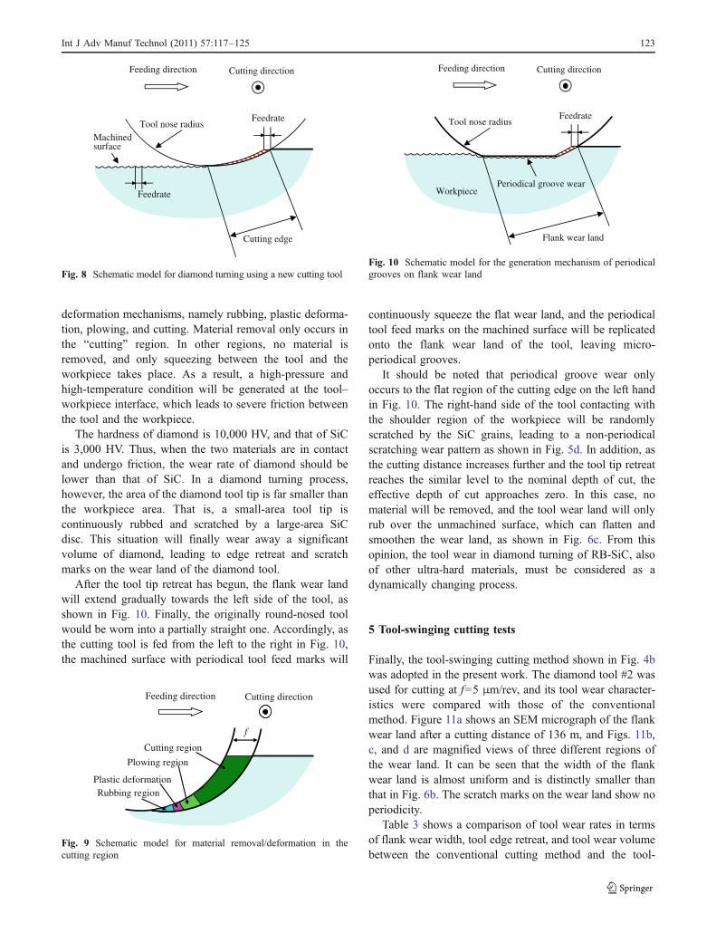
deformation mechanisms, namely rubbing, plastic deforma-tion, plowing, and cutting. Material removal only occurs inthe “cutting” region. In other regions, no material isremoved, and only squeezing between the tool and theworkpiece takes place. As a result, a high-pressure andhigh-temperature condition will be generated at the tool–workpiece interface, which leads to severe friction betweenthe tool and the workpiece.
The hardness of diamond is 10,000 HV, and that of SiCis 3,000 HV. Thus, when the two materials are in contactand undergo friction, the wear rate of diamond should belower than that of SiC. In a diamond turning process,however, the area of the diamond tool tip is far smaller thanthe workpiece area. That is, a small-area tool tip iscontinuously rubbed and scratched by a large-area SiCdisc. This situation will finally wear away a significantvolume of diamond, leading to edge retreat and scratchmarks on the wear land of the diamond tool.
After the tool tip retreat has begun, the flank wear landwill extend gradually towards the left side of the tool, asshown in Fig. 10. Finally, the originally round-nosed toolwould be worn into a partially straight one. Accordingly, asthe cutting tool is fed from the left to the right in Fig. 10,the machined surface with periodical tool feed marks will
continuously squeeze the flat wear land, and the periodicaltool feed marks on the machined surface will be replicatedonto the flank wear land of the tool, leaving micro-periodical grooves.
It should be noted that periodical groove wear onlyoccurs to the flat region of the cutting edge on the left handin Fig. 10. The right-hand side of the tool contacting withthe shoulder region of the workpiece will be randomlyscratched by the SiC grains, leading to a non-periodicalscratching wear pattern as shown in Fig. 5d. In addition, asthe cutting distance increases further and the tool tip retreatreaches the similar level to the nominal depth of cut, theeffective depth of cut approaches zero. In this case, nomaterial will be removed, and the tool wear land will onlyrub over the unmachined surface, which can flatten andsmoothen the wear land, as shown in Fig. 6c. From thisopinion, the tool wear in diamond turning of RB-SiC, alsoof other ultra-hard materials, must be considered as adynamically changing process.
5 Tool-swinging cutting tests
Finally, the tool-swinging cutting method shown in Fig. 4bwas adopted in the present work. The diamond tool #2 wasused for cutting at f=5 μm/rev, and its tool wear character-istics were compared with those of the conventionalmethod. Figure 11a shows an SEM micrograph of the flankwear land after a cutting distance of 136 m, and Figs. 11b,c, and d are magnified views of three different regions ofthe wear land. It can be seen that the width of the flankwear land is almost uniform and is distinctly smaller thanthat in Fig. 6b. The scratch marks on the wear land show noperiodicity.
Table 3 shows a comparison of tool wear rates in termsof flank wear width, tool edge retreat, and tool wear volumebetween the conventional cutting method and the tool-
Flank wear land
Workpiece
Feeding direction
Tool nose radiusFeedrate
Cutting direction
Periodical groove wear
Fig. 10 Schematic model for the generation mechanism of periodicalgrooves on flank wear land
Rubbing region
Plowing region
Cutting region
f
Plastic deformation
Feeding direction Cutting direction
Fig. 9 Schematic model for material removal/deformation in thecutting region
Cutting edge
Feedrate
Machinedsurface
Feeding direction
Tool nose radiusFeedrate
Cutting direction
Fig. 8 Schematic model for diamond turning using a new cutting tool
Int J Adv Manuf Technol (2011) 57:117–125 123

swinging cutting method. Flank wear width was directlymeasured from the SEM micrographs. Tool edge retreatwas calculated from the relief angle and the measured flankwear width. Tool wear volume was calculated using the 3-DCAD software CATIA V5 (Dassault Systèmes, S.A.,France) based on the tool wear geometry measured fromthe SEM micrographs of the tool. Due to tool swinging, theflank wear width and the tool edge retreat have beenreduced from 15.8 to 2.8 μm and from 2.8 to 0.5 μm,respectively. The tool wear volume in the tool-swingingmethod is 2,417 μm3, about 40% of that in the conventionalcutting method. Therefore, the tool wear has been not onlydistributed, but also totally reduced. As a result of toolswinging, the machined surface roughness has beenimproved from 46 nm Ra to 9 nm Ra. The significantdecrease in the retreat of tool edge in the tool-swingingcutting method will facilitate the improvement of work-piece form accuracy that was deteriorated by severe toolwear in the conventional cutting method.
The tool-swinging motion provides a continuous changeof cutting point along the cutting edge; thus, the cuttingtime for a certain cutting point becomes very short. Inaddition, the cutting edge can be effectively cooled duringthe air-cut period so that the temperature rise of the cuttingedge will be significantly reduced. In addition, the tool canbe well lubricated as it swings, because lubricants caneasily penetrate into the tool–workpiece interface. There-fore, the tool-swinging cutting method might be aneffective method to reduce tool wear in diamond turningof ultra-hard materials, although the tool-swinging motionmakes the operation sophisticated. The workpiece formerror induced by the tool-swinging error can be eliminatedby numerical control program compensation. Furtherinvestigation of the tool-swinging cutting method will bereported in another paper elsewhere.
6 Conclusions
Tool wear characteristics in diamond turning of RB-SiChave been studied by SEM observation and micro-laserRaman analysis. The following conclusions have beendrawn:
1. Flank wear is significant. The flank wear land consists oftwo regions having different wear patterns: periodicalmicrogrooves and non-periodical scratch marks. The non-periodical scratch marks may disappear as the cuttingdistance increases.
Tool feeding direction Rake face
Flank face
150 µm
Flank wear land
a
b c d
Cutting direction
Flank wear land10 µm 10 µm 10 µm
Fig. 11 SEM micrographs of the cutting edge after a cutting distance of 136 m by the tool-swinging cutting method. a general view of the flankwear land. b, c, and d are close-up views of three different regions of the flank wear land
Table 3 Comparison of tool wear rates between conventional cuttingand tool-swinging cutting
No tool swinging Tool swinging
Flank wear width (μm) 15.8 2.8
Tool edge retreat (μm) 2.8 0.5
Tool wear volume (μm3) 5,994 2,417
Surface roughness Ra (nm) 46 9
124 Int J Adv Manuf Technol (2011) 57:117–125

2. The microgrooves on the wear land are oriented alongthe cutting direction, and the pitch of the grooves is thesame as the tool feed per revolution of the workpiece.The grooves are replicated from the tool feed marks onthe machined surface.
3. Raman spectroscopy of the wear land shows that thediamond–graphite transformation does not occur duringmachining. The dominant wear mechanism is theabrasive scratching effect of the SiC grains at thetool–workpiece interface.
4. The tool-swinging cutting method can significantlyreduce tool wear and remarkably improve the cuttingperformance of the tools.
Acknowledgments The authors would like to express their sincerethanks to Japan Fine Ceramics Co., Ltd., for providing RB-SiCsamples and related technical information.
References
1. Hall C, Tricard M, Murakoshi H, Yamamoto Y, Kuriyama K,Yoko H (2005) New mold manufacturing techniques. Proc SPIE5868:58680V
2. Toshiya H, Ichiro I, Junichi S (1985) Grinding of silicon carbidewith diamond wheel, T. Jpn Soc Mech Eng C 51:1864–1870
3. Dai Y, Ohmori H, Lin W, Eto H, Ebizuka N, Tsuno K (2005)ELID grinding properties of high-strength reaction-sintered SiC.Key Eng Mater 291–292:121–126
4. Tam HY, Cheng HB, Wang YW (2007) Removal rate and surfaceroughness in the lapping and polishing of RB-SiC opticalcomponents. J Mater Process Tech 192–193:276–280
5. Cheng H, Feng Z, Lei S, Wang Y (2005) Magnetorheologicalfinishing of SiC aspheric mirrors. Mater Manuf Process20:917–931
6. Yan J, Oowada T, Zhou T, Kuriyagawa T (2009) Precisionmachining of microstructures on electroless-plated NiP surface formolding glass components. J Mater Process Tech 209:4802–4808
7. Samant A, Dahotre N (2009) Laser machining of structuralceramics. J Eur Ceram Soc 29:969–993
8. Wesch W, Heft A, Menzel R, Bachmann T, Peiter G, Hobert H,Höche T, Dannberg P, Bräuer A (1999) Ion beam processing ofSiC for optical application. Nucl Instrum Meth B 148:545–550
9. Yan J, Zhang Z, Kuriyagawa T (2009) Mechanism for materialremoval in diamond turning of reaction-bonded silicon carbide.Int J Mach Tools Manuf 49:366–374
10. Patten JA, Gao W, Yasuto K (2005) Ductile regime nano-machining of single-crystal silicon carbide. J Manuf Sci E-TASME 127:522–532
11. Suyama S, Kameda T, Itoh Y (2003) Development of high-strength reaction-sintered silicon carbide. Diam Relat Mater12:1201–1204
12. Ohta T, Yan J, Kodera S, Yajima S, Horikawa N, Takahashi Y,Kuriyagawa T (2008) Coolant effects on tool wear in machiningsingle-crystal silicon with diamond tools. Key Eng Mater 389–390:144–150
13. Gogotsi G, Kailer A, Nickel G (1999) Transformation of diamondto graphite. Nature 401:663–664
14. Yan J, Asami T, Harada H, Kuriyagawa T (2009) Fundamentalinvestigation of subsurface damage in single crystalline siliconcaused by diamond machining. Prec Eng 33(4):378–386
15. Vogelgesang R, Alvarenga AD, Kim H, Ramdas AK, Rodriguez S,Grimsditch M, Anthony TR (1998) Multiphonon Raman and infraredspectra of isotopically controlled diamond. Phys Rev B 58:5408–5416
16. Nazare MH, Neves AJ (2001) Properties, Growth and Applica-tions of Diamond. INSPEC, IEE, London
17. Yan J, Syoji K, Tamaki J (2003) Some observations on the wear ofdiamond tools in ultraprecision cutting of single-crystal silicon.Wear 255(7–12):1380–1387
18. Cai MB, Li XP, Rahman M (2007) Characteristics of “dynamichard particles” in nanoscale ductile mode cutting of monocrystal-line silicon with diamond tools in relation to tool groove wear.Wear 263:1459–1466
19. Zong WJ, Sun T, Li D, Cheng K, Liang YC (2008) XPS analysis ofthe groove wearingmarks on flank face of diamond tool in nanometriccutting of silicon wafer. Int J Mach Tools Manuf 48:1678–1687
Int J Adv Manuf Technol (2011) 57:117–125 125