Embed Size (px)
Citation preview

Ultra-directional source of longitudinal acoustic waves based on a two-dimensionalsolid/solid phononic crystalB. Morvan, A. Tinel, J. O. Vasseur, R. Sainidou, P. Rembert, A.-C. Hladky-Hennion, N. Swinteck, and P. A.Deymier Citation: Journal of Applied Physics 116, 214901 (2014); doi: 10.1063/1.4903076 View online: http://dx.doi.org/10.1063/1.4903076 View Table of Contents: http://scitation.aip.org/content/aip/journal/jap/116/21?ver=pdfcov Published by the AIP Publishing Articles you may be interested in Acoustic confinement and waveguiding in two-dimensional phononic crystals with material defect states J. Appl. Phys. 116, 024904 (2014); 10.1063/1.4889846 Multifunctional solid/solid phononic crystal J. Appl. Phys. 112, 024514 (2012); 10.1063/1.4739264 Directional enhanced acoustic radiation caused by a point cavity in a finite-size two-dimensional phononic crystal Appl. Phys. Lett. 93, 201904 (2008); 10.1063/1.3033220 Design of a highly magnified directional acoustic source based on the resonant cavity of two-dimensionalphononic crystals Appl. Phys. Lett. 89, 171912 (2006); 10.1063/1.2370382 Highly directional acoustic wave radiation based on asymmetrical two-dimensional phononic crystal resonantcavity Appl. Phys. Lett. 88, 263505 (2006); 10.1063/1.2217923
[This article is copyrighted as indicated in the article. Reuse of AIP content is subject to the terms at: http://scitation.aip.org/termsconditions. Downloaded to ] IP:
150.135.172.76 On: Thu, 03 Sep 2015 16:59:43

Ultra-directional source of longitudinal acoustic waves basedon a two-dimensional solid/solid phononic crystal
B. Morvan,1 A. Tinel,1 J. O. Vasseur,2 R. Sainidou,1 P. Rembert,1 A.-C. Hladky-Hennion,2
N. Swinteck,3 and P. A. Deymier3
1Laboratoire Ondes et Milieux Complexes, UMR CNRS 6294, Universit�e du Havre, 75 rue Bellot, 76058 LeHavre, France2Institut d’Electronique, de Micro-�electronique et de Nanotechnologie, UMR CNRS 8520, Cit�e Scientifique,59652 Villeneuve d’Ascq Cedex, France3Department of Materials Science and Engineering, University of Arizona, Tucson, Arizona 85721, USA
(Received 25 July 2014; accepted 14 October 2014; published online 2 December 2014)
Phononic crystals (PC) can be used to control the dispersion properties of acoustic waves, which
are essential to direct their propagation. We use a PC-based two-dimensional solid/solid composite
to demonstrate experimentally and theoretically the spatial filtering of a monochromatic non-
directional wave source and its emission in a surrounding water medium as an ultra-directional
beam with narrow angular distribution. The phenomenon relies on square-shaped equifrequency
contours (EFC) enabling self-collimation of acoustic waves within the phononic crystal.
Additionally, the angular width of collimated beams is controlled via the EFC size-shrinking when
increasing frequency. VC 2014 AIP Publishing LLC. [http://dx.doi.org/10.1063/1.4903076]
I. INTRODUCTION
For numerous applications of acoustic waves, it is highly
desirable to produce directional sources of sound. This is
particularly true in the area of underwater acoustics, where
directivity of longitudinal waves is required for point-to-
point communications or precise echolocation. The literature
reports a variety of ways to realize directional acoustic sour-
ces.1–4 In general, these sources exploit the anisotropy and/or
symmetry of some heterogeneous media such as phononic
crystals (PCs). These are composite structures constituted of
different materials arranged in a periodic manner. For exam-
ple, two dimensional PCs are typically composed of periodic
arrays of cylindrical inclusions embedded in a matrix made
of some other material with different elastic parameters
(mass density q and longitudinal and transverse wave propa-
gation velocities, cl and ct, respectively). The geometry and
the contrast in physical and acoustical properties of the con-
stituent materials determine the dispersive properties of
PCs.5 By controlling the dispersion characteristics, one can
achieve peculiar properties that are not available in natural
materials.6 Directional acoustic sources developed so far
have exploited the four-folds symmetry of square lattices of
inclusions,7,8 inspired by similar behavior encountered in the
area of photonics (see, for instance, Ref. 9). This symmetry
leads to propagation of acoustic waves constrained to spe-
cific directions. Self-collimation of acoustic beams inside the
PC volume may result from the square symmetry of specific
passing bands in some frequency domain.10,11 In addition,
the acoustic band structure of PCs can show angular band
gaps that can be used as spatial filters of monochromatic
sources.12,13 These angular band gaps forbid the transmission
of waves in some range of directions subsequently narrowing
the angular distribution of acoustic beams. In this paper, we
exploit both phenomena to achieve an ultra-directional sound
source.
Up to date, the use of these refractive and transmission
properties to produce directional acoustic sources of longitu-
dinal waves have been demonstrated only for solid/fluid
PCs.2,3,7,8,14–16 These structures, constituted of solid inclu-
sions in a fluid matrix (e.g., air or water), present several
drawbacks regarding ease of handling and use in another
fluid medium. Collimation in a potentially more advanta-
geous 2D solid/solid PC has been shown but for elastic trans-
verse waves17 that cannot be supported by an external fluid
medium. Here, we focus on a solid/solid PC that can be eas-
ily handled for practical applications in underwater acous-
tics. We demonstrate experimentally and theoretically, the
possibility of constructing an efficient ultra-directional
source of longitudinal waves using a PC structure made of
steel rods embedded in epoxy resin matrix with a lattice con-
stant of the order of a few mm. Some of us have previously
shown19 that this PC exhibits equi-frequency contours
(EFCs) of quasi-square shape in some ultrasonic frequency
range and consequently behaves as a self-collimator for lon-
gitudinal acoustic waves. We further analyze theoretically
the related behavior and provide insights on the band struc-
ture, symmetry, and extent of EFCs, as well as the angular
dependency of transmission of longitudinal waves in that
PC. The EFCs show angular band gaps, which widen by
increasing frequency, thus, allowing efficient angular filter-
ing of the collimated beam. Next, underwater ultrasonic
experiments are performed by introducing a primary multi-
directional pinducer source at the PC center. The whole
structure operates like an ultra-directional source with an
emitted beam in surrounding water exhibiting a divergence
of the order of just a few degrees.
The paper is organized as follows. In Sec. II, we present
the fundamental, theoretically predicted, properties of the
system under consideration and describe the fabricated sam-
ple and the experimental setup. Experimental results are
reported and discussed in Sec. III. Excellent agreement
0021-8979/2014/116(21)/214901/6/$30.00 VC 2014 AIP Publishing LLC116, 214901-1
JOURNAL OF APPLIED PHYSICS 116, 214901 (2014)
[This article is copyrighted as indicated in the article. Reuse of AIP content is subject to the terms at: http://scitation.aip.org/termsconditions. Downloaded to ] IP:
150.135.172.76 On: Thu, 03 Sep 2015 16:59:43
between predictions and measurements is established and the
physical mechanisms at play in the processes of collimation
and spatial filtering are analyzed. Finally, conclusions are
drawn in Sec. IV with some attention paid to perspectives
relative to the application of this ultra-directional PC.
II. PHONONIC CRYSTAL STRUCTURE ANDEXPERIMENTAL SETUP
A. Structure and properties
The PC consists of parallel steel cylinders of radius
R¼ 1 mm, arranged in a square lattice of lattice constant
a¼ 3.23 mm and embedded in an epoxy resin matrix. The
elastic parameters for the materials considered are given in
Table I. The corresponding volume filling fraction of metal
rods, defined as / ¼ pðR=aÞ2, equals 0.30. The band struc-
ture of a PC assumed of infinite extent in the three dimen-
sions is calculated using the layer-multiple-scattering
technique adapted to treat 2D PC.18 In the case under study,
the calculation is restricted to modes, whose displacement
field and wave vector lie on the xy-plane perpendicular to the
inclusions (XY modes). The band structure is shown in Fig.
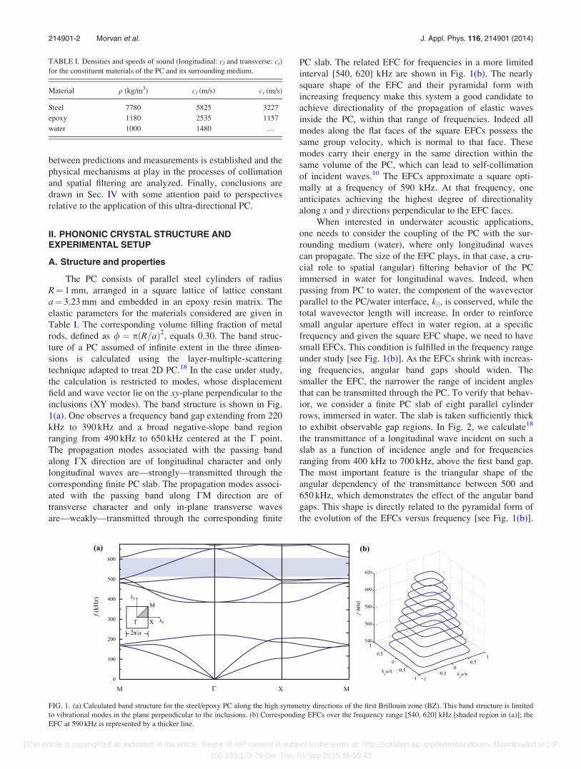
1(a). One observes a frequency band gap extending from 220
kHz to 390 kHz and a broad negative-slope band region
ranging from 490 kHz to 650 kHz centered at the C point.
The propagation modes associated with the passing band
along CX direction are of longitudinal character and only
longitudinal waves are—strongly—transmitted through the
corresponding finite PC slab. The propagation modes associ-
ated with the passing band along CM direction are of
transverse character and only in-plane transverse waves
are—weakly—transmitted through the corresponding finite
PC slab. The related EFC for frequencies in a more limited
interval [540, 620] kHz are shown in Fig. 1(b). The nearly
square shape of the EFC and their pyramidal form with
increasing frequency make this system a good candidate to
achieve directionality of the propagation of elastic waves
inside the PC, within that range of frequencies. Indeed all
modes along the flat faces of the square EFCs possess the
same group velocity, which is normal to that face. These
modes carry their energy in the same direction within the
same volume of the PC, which can lead to self-collimation
of incident waves.10 The EFCs approximate a square opti-
mally at a frequency of 590 kHz. At that frequency, one
anticipates achieving the highest degree of directionality
along x and y directions perpendicular to the EFC faces.
When interested in underwater acoustic applications,
one needs to consider the coupling of the PC with the sur-
rounding medium (water), where only longitudinal waves
can propagate. The size of the EFC plays, in that case, a cru-
cial role to spatial (angular) filtering behavior of the PC
immersed in water for longitudinal waves. Indeed, when
passing from PC to water, the component of the wavevector
parallel to the PC/water interface, kjj, is conserved, while the
total wavevector length will increase. In order to reinforce
small angular aperture effect in water region, at a specific
frequency and given the square EFC shape, we need to have
small EFCs. This condition is fulfilled in the frequency range
under study [see Fig. 1(b)]. As the EFCs shrink with increas-
ing frequencies, angular band gaps should widen. The
smaller the EFC, the narrower the range of incident angles
that can be transmitted through the PC. To verify that behav-
ior, we consider a finite PC slab of eight parallel cylinder
rows, immersed in water. The slab is taken sufficiently thick
to exhibit observable gap regions. In Fig. 2, we calculate18
the transmittance of a longitudinal wave incident on such a
slab as a function of incidence angle and for frequencies
ranging from 400 kHz to 700 kHz, above the first band gap.
The most important feature is the triangular shape of the
angular dependency of the transmittance between 500 and
650 kHz, which demonstrates the effect of the angular band
gaps. This shape is directly related to the pyramidal form of
the evolution of the EFCs versus frequency [see Fig. 1(b)].
TABLE I. Densities and speeds of sound (longitudinal: cl and transverse: ct)
for the constituent materials of the PC and its surrounding medium.
Material q (kg/m3) cl (m/s) ct (m/s)
Steel 7780 5825 3227
epoxy 1180 2535 1157
water 1000 1480 …
FIG. 1. (a) Calculated band structure for the steel/epoxy PC along the high symmetry directions of the first Brillouin zone (BZ). This band structure is limited
to vibrational modes in the plane perpendicular to the inclusions. (b) Corresponding EFCs over the frequency range [540, 620] kHz [shaded region in (a)]; the
EFC at 590 kHz is represented by a thicker line.
214901-2 Morvan et al. J. Appl. Phys. 116, 214901 (2014)
[This article is copyrighted as indicated in the article. Reuse of AIP content is subject to the terms at: http://scitation.aip.org/termsconditions. Downloaded to ] IP:
150.135.172.76 On: Thu, 03 Sep 2015 16:59:43
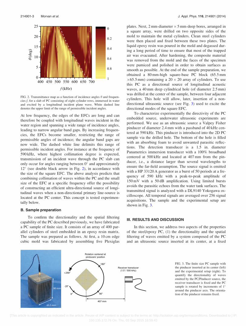
At low frequency, the edges of the EFCs are long and can
therefore be coupled with longitudinal waves incident in the
water region and spanning a wide range of incidence angles,
leading to narrow angular band gaps. By increasing frequen-
cies, the EFCs become smaller, restricting the range of
permissible angles of incidence; the angular band gaps are
now wide. The dashed white line delimits this range of
permissible incident angles. For instance at the frequency of
590 kHz, where highest collimation degree is expected,
transmission of an incident wave through the PC slab can
only occur for angles ranging between 0� and approximately
12� (see double black arrow in Fig. 2), in accordance with
the size of the square EFC. The above analysis predicts that
combining collimation of waves within the PC and the small
size of the EFC at a specific frequency offer the possibility
of constructing an efficient ultra-directional source of longi-
tudinal waves when a non-directional primary line-source is
located at the PC center. This concept is tested experimen-
tally below.
B. Sample preparation
To confirm the directionality and the spatial filtering
capability of the PC described previously, we have fabricated
a PC sample of finite size. It consists of an array of 400 par-
allel cylinders of steel embedded in an epoxy resin matrix.
The sample was prepared as follows. At first, a 10 cm edge
cubic mold was fabricated by assembling five Plexiglas
plates. Next, 2 mm-diameter� 5 mm-deep bores, arranged in
a square array, were drilled on two opposite sides of the
mold to maintain the metal cylinders. Clean steel cylinders
were then placed and fixed between these two plates. The
liquid epoxy resin was poured in the mold and degassed dur-
ing a long period of time to ensure that most of the trapped
air was evacuated. After hardening, the composite material
was removed from the mold and the faces of the specimen
were pumiced and polished in order to obtain surfaces as
smooth as possible. At the end of the sample preparation, we
obtained a 80 mm-high square-base PC block (65:5 mm
�65:5 mm) containing a 20� 20 array of cylinders. To use
this PC as a directional source of longitudinal acoustic
waves, a 40 mm deep cylindrical hole (of diameter 2.5 mm)
was drilled at the center of the sample, between four adjacent
cylinders. This hole will allow, later, insertion of a non-
directional ultrasonic source (see Fig. 3) used to excite the
directional modes of the square EFC.
To characterize experimentally the directivity of the PC
embedded source, underwater ultrasonic experiments are
performed. We use as an ultrasonic source a Valpey Fisher
pinducer of diameter 2.4 mm with a passband of 40 kHz cen-
tered at 590 kHz. This pinducer is introduced into the 2D PC
sample via the drilled hole. The bottom of the hole is filled
with an absorbing foam to avoid unwanted parasitic reflec-
tions. The detection transducer is a 1.5 in. diameter
Panametrics immersion transducer with a 100% broadband
centered at 500 kHz and located at 407 mm from the pin-
ducer, i.e., a distance larger than several wavelengths to
ensure the far-field assumption. The source signal is emitted
with a HP 33120 A generator as a burst of 50 periods at a fre-
quency of 590 kHz with a peak-to-peak amplitude of
150 mV with a 50 dB amplification. Using limited bursts
avoids the parasitic echoes from the water tank surfaces. The
transmitted signal is analyzed with a DL9140 Yokogawa os-
cilloscope. All temporal signals are averaged over 256 signal
acquisitions. The sample and the experimental setup are
shown in Fig. 3.
III. RESULTS AND DISCUSSION
In this section, we address two aspects of the properties
of the steel/epoxy PC, (1) the directionality and the spatial
filtering of waves emitted by a system composed of the PC
and an ultrasonic source inserted at its center, at a fixed
FIG. 2. Transmittance map as a function of incidence angles h and frequen-
cies f, for a slab of PC consisting of eight cylinder rows, immersed in water
and excited by a longitudinal incident plane wave. White dashed line
denotes the upper limit of the range of permissible incident angles.
FIG. 3. The finite size PC sample with
the pinducer inserted at its center (left)
and the experimental setup (right). To
quantify the directionality of waves
emitted by the PC/Pinducer source, the
receiver transducer is fixed and the PC
sample is rotated by increments of 1�
around the pinducer axis. The orienta-
tion of the pinducer remains fixed.
214901-3 Morvan et al. J. Appl. Phys. 116, 214901 (2014)
[This article is copyrighted as indicated in the article. Reuse of AIP content is subject to the terms at: http://scitation.aip.org/termsconditions. Downloaded to ] IP:
150.135.172.76 On: Thu, 03 Sep 2015 16:59:43

frequency of 590 kHz and (2) the effect of the frequency of
the source on the directionality.
A. Directionality and spatial filtering of waves
We first characterize the directionality of the pinducer ul-
trasonic source without the PC. The receiver transducer is fixed
and the diagram of directivity is obtained by performing a rota-
tion of the pinducer along its axis. The resulting diagram at a
frequency of 590 kHz is given in Fig. 4(a). The non-circular
shape of this diagram reveals that the pinducer source is not iso-
tropic. Indeed the amplitude along the 0� direction is 2.5 times
higher than the amplitude along the 90� direction. Then, the pin-
ducer is inserted into the PC. The end of the pinducer is located
at 35 mm from the top surface of the PC sample. The orientation
of the pinducer is maintained at the value of 0� relative to the
detector. The directivity properties of waves propagating
through the PC and into the surrounding water are analyzed by
rotating the PC with respect to its vertical axis by increments of
1�. The collected signals are measured at each angular position.
The fact that the pinducer remains fixed allows us to overcome
its anisotropy and only characterize the directionality of waves
emitted through the PC. Excluding the transient part of the
burst, we measure the amplitude of the transmitted signal in the
steady-state regime. The resulting diagram of directivity show-
ing the amplitude versus angular position is plotted in Fig. 4(b).
We observe, as expected, the maxima of transmission in the
four directions 0�, 90�, 180�, and 270�. This representation
allows us to estimate an angular divergence of the four colli-
mated and spatially filtered beams equal to 64�.We have verified theoretically the directionality and spa-
tial filtering ability of the finite PC immersed in water by
performing finite difference time domain (FDTD) calcula-
tions.19 The model system is identical to that considered
experimentally. An isotropic point source is used to emit lon-
gitudinal waves at the center of the PC. This point source
mimics the experimental pinducer. The calculated pressure
field clearly shows self-collimation of waves inside the PC
volume along the four principal directions that the group ve-
locity can take. The experimental angular distribution of Fig.
4(b) compares well with the pressure field calculated with
the FDTD method of Fig. 4(c). Both show that outside the
PC, the four beams that propagate in the surrounding water
exhibit a rather small spreading. The PC/pinducer system
behaves as a spatial filter and can serve as a highly direc-
tional source for underwater longitudinal waves.
We note here that the transmitted signal is significantly
weakened when the pinducer is inserted into the PC-block
[Fig. 4(b)], compared to the corresponding radiated signal
level of the pinducer immersed directly in water [Fig. 4(a)].
Of course, this level loss can be improved with an appropri-
ate choice of the host material in order to adapt the imped-
ance at the interface between water and host matrix (here
epoxy), responsible for high level reflection when elastic
waves pass across it.20
B. Effect of frequency
In order to obtain the evolution of the directivity of wave
emission versus the frequency, a fast Fourier transform is
applied on the received signal for each angular position.
Despite a single frequency burst excitation, frequency compo-
nents contained in the transient part of the temporal incident
signal allow us to extract information on a wide frequency
band (see Fig. 5). One clearly sees the transmission-gap region
FIG. 4. Experimental maximum-amplitude (in arbitrary units) angular plot
of signal received from the pinducer (a) immersed in water, (b) embedded in
the PC block and immersed in water, and (c) pressure field (in arbitrary
units) calculated using the FDTD method for case (b).
214901-4 Morvan et al. J. Appl. Phys. 116, 214901 (2014)
[This article is copyrighted as indicated in the article. Reuse of AIP content is subject to the terms at: http://scitation.aip.org/termsconditions. Downloaded to ] IP:
150.135.172.76 On: Thu, 03 Sep 2015 16:59:43

extending from 200 to 400 kHz. As seen before, within the
frequency region above the gap, the measured intensity of the
signal is maximum at the angles 0�, 90�, 180�, and 270�,which corresponds to the four principal directions of transmis-
sion of the PC associated with the square symmetry of the
EFCs [see Fig. 1(b)]. Maximum of transmission is obtained at
a frequency of 587 kHz. Beyond this frequency, only weak
non-directional transmission is observed due to the possible
excitation of additional modes [see Fig. 1(a)]. The angular
spread of the directed transmitted waves increases as the fre-
quency decreases, in accordance with what we described in
Subsection II A. In Fig. 5, we have drawn white lines that
delimit the permissible angles that propagating waves can
take (see Fig. 2). The white triangles form borders between
the passing bands and the angular band gaps of the PC’s
EFCs. As frequency increases, the angular band gaps widen
narrowing the angular distribution of the beam. In addition,
secondary maxima occur at angles around 45�, 135�, and
225�. These maxima are particularly noticeable for frequen-
cies near 590 kHz. They originate from the intersection of two
secondary beams, each one of them emerging from adjacent
faces of the PC-block at angles of 652� with respect to the
main beam axis. The existence of these beams was reported in
Ref. 19. While the primary directional beams result from the
excitation of modes in the first Brillouin zone (BZ) of the PC,
these secondary beams correspond to the excitation of dif-
fracted beams of higher order, visible in Fig. 4(c). These sec-
ondary beams will intersect at a distance of ’211 mm
(almost the half of that between the center of the PC and the
detector) and will form an extended region of detectable inten-
sity at the position of the detector (see Fig. 6). The symmetry
of the system leads to four of these extended detectable
regions centered approximately at the angles of 45�, 135�,225�, and 315�. Only three of these extended regions are
observable in Fig. 5 due to geometrical constraints imposed
by our experimental setup.
IV. CONCLUSIONS
We have studied theoretically and experimentally the di-
rectivity properties of acoustic waves for a 2D PC made of a
square array of steel cylinders embedded in epoxy matrix in
which we inserted a non-directional ultrasonic pinducer source.
The whole PC/pinducer structure is immersed in water. In par-
ticular, we demonstrated that this system serves as an ultra-
directional source of longitudinal waves in the surrounding me-
dium, near the frequency of 590 kHz. The phenomenon relies
on square-shaped EFCs of the corresponding PC in the fre-
quency range [500, 600] kHz, which shrink by increasing fre-
quency. Consequently, collimation of acoustic waves takes
place together with angular filtering of the acoustic beam in the
water region. By symmetry, four such narrow beams are emit-
ted by the system. These intense primary beams are accompa-
nied by significantly weaker secondary ones (resulting from
higher order diffraction) that affect only marginally the per-
formance of the PC/pinducer system as ultra-directional source
of acoustic waves. This study opens interesting perspectives in
the design of source of acoustic waves for underwater applica-
tions by taking advantage of the unique characteristics of PCs.
In particular, the ability to engineer the band structures of PCs
gives a tremendous advantage in the design of spatial filters
and directional sources of acoustics waves.
1Liang-Shan Chen, Chao-Hsien Kuo, and Z. Ye, “Acoustic imaging and
collimating by slabs of sonic crystals made from arrays of rigid cylinders
in air,” Appl. Phys. Lett. 85, 1072 (2004).2C. Qiu and Z. Liu, “Acoustic directional radiation and enhancement
caused by band-edge states of two-dimensional phononic crystals,” Appl.
Phys. Lett. 89, 063106 (2006).3C. Qiu, Z. Liu, J. Shi, and C. T. Chan, “Directional acoustic source based
on the resonant cavity of two-dimensional phononic crystals,” Appl. Phys.
Lett. 86, 224105 (2005).4A. Hakansson, D. Torrent, F. Cervera, and J. S�anchez-Dehesa,
“Directional acoustic source by scattering acoustical elements,” Appl.
Phys. Lett. 90, 224107 (2007).5Y. Pennec, J. O. Vasseur, B. Djafari-Rouhani, L. Dobrzynski, and P. A.
Deymier, “Two-dimensional phononic crystals: Examples and
applications,” Surf. Sci. Rep. 65, 229 (2010).
FIG. 6. Schematic of the secondary beams emerging from the PC block at
angles 652� with respect to the normal to each face of the PC (represented
as a square). The largest circle represents the position of the detector.
Secondary beams from adjacent faces intersect at approximately 211 mm
(dashed line circle). They form on the detection circle, extended regions
with finite intensity (still lower than that of the primary directional beams)
centered at the angles 45�, 135�, 225�, and 315�.
FIG. 5. Variation of experimental received pressure in the angle-frequency
domain. Color scale is in arbitrary units.
214901-5 Morvan et al. J. Appl. Phys. 116, 214901 (2014)
[This article is copyrighted as indicated in the article. Reuse of AIP content is subject to the terms at: http://scitation.aip.org/termsconditions. Downloaded to ] IP:
150.135.172.76 On: Thu, 03 Sep 2015 16:59:43

6In Acoustic Metamaterials and Phononic Crystals, Springer Series in
Solid-State Sciences Vol. 173, edited by P. A. Deymier (Springer, Berlin,
2013).7J. Mei, C. Qiu, J. Shi, and Z. Liu, “Enhanced and directional water wave
emission by embedded sources,” Wave Motion 47, 131 (2010).8Tsung-Tsong Wu, Chung-Hao Hsu, and Jia-Hong Sun, “Design of a highly
magnified directional acoustic source based on the resonant cavity of two-
dimensional phononic crystals,” Appl. Phys. Lett. 89, 171912 (2006).9S. Enoch, B. Gralak, and G. Tayeb, “Enhanced emission with angular con-
finement from photonic crystals,” Appl. Phys. Lett. 81, 1588 (2002).10J. Bucay, E. Roussel, J. O. Vasseur, P. A. Deymier, A.-C. Hladky-
Hennion, Y. Pennec, K. Muralidharan, B. Djafari-Rouhani, and B. Dubus,
“Positive, negative, zero refraction, and beam splitting in a solid/air pho-
nonic crystal: Theoretical and experimental study,” Phys. Rev. B 79,
214305 (2009).11V. Espinosa, V. J. S�anchez-Morcillo, K. Staliunas, I. P�erez-Arjona, and J.
Redondo, “Subdiffractive propagation of ultrasound in sonic crystals,”
Phys. Rev. B 76, 140302(R) (2007).12R. Pic�o, I. P�erez-Arjona, V. J. S�anchez-Morcillo, and K. Staliunas,
“Evidences of spatial (angular) filtering of sound beams by sonic crystals,”
Appl. Acoust. 74, 945 (2013).13V. Romero-Garc�ıa, R. Pic�o, A. Cebrecos, K. Staliunas, and V. J. Sanchez-
Morcillo, “Angular band gaps in sonic crystals: Evanescent waves and
spatial complex dispersion relation,” J. Vib. Acoust. 135, 041012 (2013).14Z. Wang, P. Zhang, Y. Zhang, and X. Nie, “Experimental verification of
directional liquid surface wave emission at band edge frequencies,”
Physica B 431, 75 (2013).
15Feng-Chia Hsu, Tsung-Tsong Wu, Jin-Chen Hsu, and Jia-Hong Sun,
“Directional enhanced acoustic radiation caused by a point cavity in a fi-
nite size two-dimensional phononic crystal,” Appl. Phys. Lett. 93, 201904
(2008).16J. Mei, C. Qiu, J. Shi, and Z. Liu, “Highly directional liquid surface wave
source based on resonant cavity,” Phys. Lett. A 373, 2948 (2009).17W. Liu and X. Su, “Collimation and enhancement of elastic transverse
waves in two-dimensional solid phononic crystals,” Phys. Lett. A 374,
2968 (2010).18R. Sainidou, P. Rembert, J. O. Vasseur, and A.-C. Hladky-Hennion, “The
layer-multiple-scattering method as applied to two-dimensional phononic
crystals,” in Proceedings of Phononics 2013: 2nd InternationalConference on Phononic Crystals/Metamaterials, Phonon Transport andOptomechanics, Sharm El-Sheikh, Egypt, 2–7 June 2013.
19N. Swinteck, J. O. Vasseur, A. C. Hladky-Hennion, C. Cro€enne, S.
Bringuier, and P. A. Deymier, “Multifunctional solid/solid phononic
crystal,” J. Appl. Phys. 112, 024514 (2012).20The elastic parameters mismatch between water and epoxy is due to the
difference in the longitudinal velocity (the mass densities are close to each
other). One should use a polymer matrix, whose longitudinal velocity
approaches that of water (of the order of 1500 m/s) and with the same
Poisson ratio as that of the epoxy (�¼ 0.36). Such a material still ensures a
band structure of the same form as the one shown in Fig. 1, although
shifted at lower frequencies (the frequency axis of the dispersion plot is
multiplied by a factor 1500=2535 � 0:6; the operating frequency 590 kHz
is now shifted to 350 kHz). As an example, one can consider NyrimVR
1525
(see http://www.matweb.com).
214901-6 Morvan et al. J. Appl. Phys. 116, 214901 (2014)
[This article is copyrighted as indicated in the article. Reuse of AIP content is subject to the terms at: http://scitation.aip.org/termsconditions. Downloaded to ] IP:
150.135.172.76 On: Thu, 03 Sep 2015 16:59:43