Embed Size (px)
Citation preview
N A S A T E C H N I C A L NOTE
m Ih 0 T n z+ 4 w3 4 z
STATIC STABILITY CHARACTERISTICS OF SEVERAL RAKED-OFF CIRCULAR AND ELLIPTICAL CONES AT MACH 6.7
by Pete?9
I Langley1 J
LangleyI b
NATIONAL AERONAUTICS AND SPAc, A D M I N I S T R A T I O N WASHINGTON, D. C. e OCTOBER 1 9 6 5
https://ntrs.nasa.gov/search.jsp?R=19650025304 2018-07-10T15:24:57+00:00Z

TECH LIBRARY KAFB, NM
Illllll11lllllllllIIIIIlllllllllIll1Ill1 0130121
NASA TN D-3053
STATIC STABILITY CHARACTERISTICS OF SEVERAL RAKED-OFF
CIRCULAR AND ELLIPTICAL CONES AT MACH 6.7
By Peter T. Bernot
Langley Research Center Langley Station, Hampton, Va.
NATIONAL AERONAUTICS AND SPACE ADMINISTRATION
For sale by the Clearinghouse for Federal Scientif ic and Technical Information Springfield, Virginia 22151 - Price $1.00

STATIC STABILITY CHARACTEFiISTICS OF SEVERAL RAKED-OFF'
CIRCULAR AND ELLIPTICAL CONES AT MACH 6.7
By Peter T. Bernot Langley Research Center
SUMMARY
Longitudinal and lateral-directional aerodynamic characteristics of four circular cones and one elliptical cone were determined at a Mach number of 6.7 and were compared with Newtonian estimates. These models employed a range of rake-off angles from 6 8 O to 51° that yielded estimated lift-drag ratios from
I 0.40to 0.80 at Oo angle of attack. The measured values of normal- and axial1 force coefficients exceeded predicted values by up to 13 percent over the test
angle-of-attack range from Oo to loo; the pitching-moment coefficients showed better agreement with theory. The circular-cone models yielded fair and good agreement with theory for the longitudinal and lateral-directional stability derivatives, respectively, whereas the elliptical-cone model showed excellent agreement. Also, good agreement between theory and experiment was obtained for the liPt-drag ratios on the elliptical-cone model, but the data for the
I
I circular-cone models were 5 to 7.5 percent lower than the predicted values. The experimental data for the complete reentry vehicle confirm that the direc-
I tional stability limit dictates center-of-gravity location for circular cones I whereas the longitudinal stability limit is the deciding criterion for ellipti
cal cones.
INTRODUCTION
The advantages of lift capability during atmospheric entry have led to consideration of a heat-shield concept for reentry from superorbital flights.Incorporation of an asymmetric heat shield with an afterbody module is discussed in reference 1. The heat-shield configuration is envisioned as either a right circular cone or an elliptical cone that is raked off at a prescribed angle to yield a desired lift-drag ratio at the trim angle of attack. A detailed theoretical study of the aerodynamic characteristics of raked-off circular-cone and elliptical-cone configurations is presented in reference 2.
The purpose of this paper is to provide hypersonic stability data on sev-II eral heat shields for comparison with theoretical estimates. Four circular-cone I mod?ls and one elliptical-cone model were tested at a Mach number of 6.7. The
cone models incorporated rake-off angles that yielded estimated values of lift-drag ratios ranging from 0.40 to 0.80at an angle of attack of Oo. Static stability CharacterisLics are presented herein as determined from balance-measured

forces and moments over an angle-of-attack range from Oo to 10' and over a sideslip range from Oo to 8 O at an angle of attack of Oo. Also, stability limits are presented for the heat-shield configuration combined with an after-body module to form a complete reentry vehicle.
SYMBOLS
Measurements for this investigation were taken in the U.S. Customary System of Units. Equivalent values are indicated herein parenthetically in the International System (SI) in the interest of promoting use of this system in future NASA reports. Details concerning the use of SI, together with physical constants and conversion factors, are given in reference 3.
axial-force coefficient, Axial force qs
rolling-moment coefficient, Rolling m0me.n-t qSd
pitching-moment coefficient, Pitching mom-ent qSd
yawing-moment coefficient, Yawing moment qSd
normal-force coefficient, Normal force qs
pressure coefficient
Side forceside-force coefficient, qs
rolling-moment-curve slope, aB '"at p = Oo, per deg
pitching-moment-curve slope, - at u = Oo, per degaa
normal-force-curve slope, - at a = Oo, per degha
acnyawing-moment-curve slope, - at p = Oo, per degaP

I a%side-force-curve slope, - at p = Oo, per degaP
d model reference diameter, in. (cm)
2 model length, in. (cm)
lift-drag ratio
stagnation pressure, atm (N/m2)
free-stream dynamic pressure, lb/ft2 (N/m2)
R free-stream Reynolds number, per inch (per 2.54 cm)
S reference area, rrd2/4
Tt stagnation temperature, OF (%)
Cartesian body axes
distance along X- and Z-ax i s , respectively
U angle of attack, deg
P angle of sideslip, deg
6 rake-off angle, deg (see fig. 1)
8 cone half-angle, deg
cone half-angle measured in horizontal plane, deg
cone half-angle measured in vertical plane, deg
APPARATUS, MODELS, AND TFSTS
The tests were conducted in the Langley 11-inch hypersonic tunnel, which is a blowdown-to-vacuum type of tunnel. A two-dimensional, contoured nozzle fabricated from invar was used to produce a Mach number slightly under 7. TO avoid liquefaction, dried air was passed through an electrically heated bundle of high-temperature nickel-chromium tubes. A more detailed description of this facility as well as nozzle calibrations may be found in references 4 and 5.
Stagnation temperature was measured by a chromel-alumel thermocouple whose output was recorded on a strip-chart potentiometer. Stagnation pressure was
3

read from a Bourdon gage. Angle of attack was measured optically by reflecting a light beam off a small prism mounted in the model-base region on to a calibrated scale. A six-component strain-gage balance was used in conjunction with strip-chart potentiometers to measure model forces and moments. A circular windshield of 0.7O-inch (1.78-centimeter) diameter protected the balance from the airstream. Measurements of windshield chamber pressures were made by use of bellows-type gages. Schlieren photographs were obtained with a system that has a vertical Z-shape light path in conjunction with a horizontal knife edge.
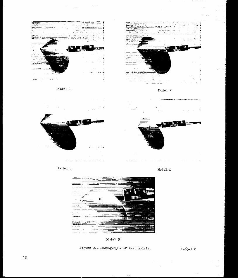
The five test models were constructed from aluminum. Model details and the body-axis system are presented in figure 1. Photographs of the models are shown in figure 2. Rake-off angles of 680, 59O, and 51° were selected for the circular-cone models 1, 2, and 3, respectively. Theoretical estimates of reference 2 indicated lift-drag ratios of 0.40, 0.60, and 0.81,respectively, at Oo angle of attack. Model 4 had a rake-off angle of 59O with a cone half-angle of 40° as compared with 35O for the other three circular-cone models. The elliptical-conemodel 5 had a cone half-angle of 30° as viewed in a vertical plane and incorporated a rake-off angle of 57O which yielded a calculated lift-drag ratio of 0.60. In order to provide a circular base, the half-angle in the horizontal plane was 36.6O.
The longitudinal stability tests covered an angle-of-attack range from 0' to loo; directional stability tests were made over a sideslip range from Oo to 8O at Oo angle of attack. Model 4 was not included in the sideslip tests. The average free-stream Mach number was 6.74 and 6.78 for the longitudinal and lateral-directionaltests, respectively. Pertinent test conditions are as follows:
Longitudinal tests: Models 1, 2, 3, and 4 Model 5
Pt' atm (m/m2) . . . . . . . . . . . 7.7 (0.8) 7.7 (0.8) T t , O F (OK) . . . . . . . . . . . . . 665 (625) 700 (644) R, per inch ( p e r 2.54 cm) . . . . . . 0.085 x io6 0.082 x lo6
Directional tests: Models 1, 2, and 3 Model 5
atm (m/m2) . . . . . . . . . . . 11.6 (1.2) 10.0(1.0) Pt, O F (OK). . . . . . . . . . . . . 660 (622) 675 (630)Tt!R, per inch (per 2.54 cm) . . . . . . 0.12 x 10⁶ 0.10x 10⁶
Schlieren photographs were obtained during each blowdown run and are presented in figure 3 for Oo angle of attack. Each blowdown run had a duration of about 40 seconds.
DATA ACC'URACY
An estimate of balance maximum error is based on 0.5 percent of the maximum design load of each component. The force and moment errors, expressed in coefficient form, are as follows:
4

Longitudinal tests: Models 1 and 2 Models 3 and 4 Model 5
C N . . . . . e . . 0.023 0.041 0.003 C A . . . . . . . . . . . . . . . .014 .026 .005 G . . . . . . . . . . . . . . . .030 .66 .002
Directional tests: Models 1 and 2 Model 3 .Model5
cz . . . . . . . . . . . . . . . 0.003 0.008 0.0005 c,............... .023 .041 .002 cy . . . . . . . . . . . . . . . .010 ,017 .003
Maximum error in angle-of-attack and sideslip settings is estimated to be kO.l5O and kO.25O, respectively. Accuracy of Mach number is taken to be k0.04.
RESULTS AND DISCUSSION
Comparison of Basic Data with Theory
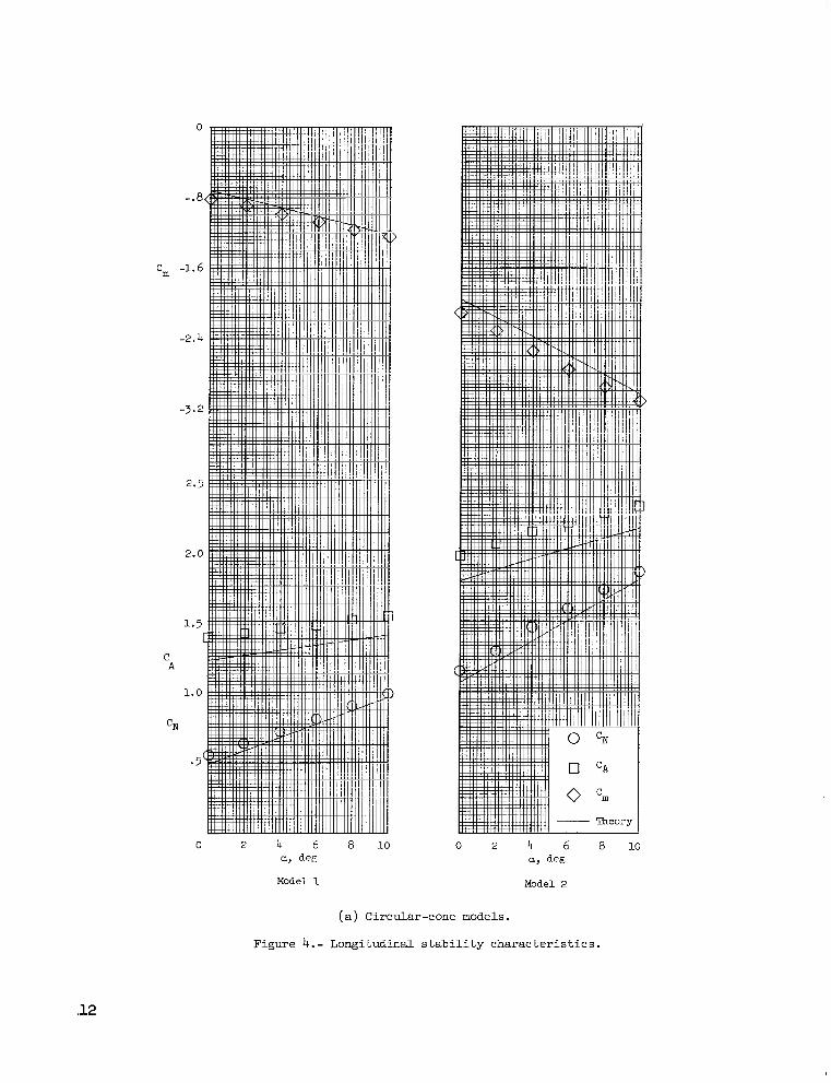
The longitudinal aerodynamic characteristics of the models are compared with Newtonian-theory predictions (ref. 2 ) in figure 4; a value of 2.0 was used for maximum Cp in the Newtonian estimates. In general, the trends of the measured data are essentially linear and in good agreement with theoretical predictions for the three parameters presented. However, the measured values of normal- and axial-force coefficients are greater than those predicted by theory; a maximum difference of 1 3 percent is noted at Oo angle of attack.
Base pressures measured on the elliptical-conemodel at Oo angle of attack showed an average value for Cp of -0.061. Corresponding incremental values of 0.003 and 0.005 were calculated for normal- and axial-force coefficients, respectively. These incremental values represent only about 10 percent of the difference between the measured and theoretical values.
For the circular-cone models at Oo angle of attack, the measured pitching-moment coefficients are 4 to 9 percent greater than predicted; these deviations decreased to 3 percent or less at 10' angle of attack. For the elliptical-conemodel 5 the predicted and measured values of pitching-moment coefficient are in good agreement.
The lateral-directional aerodynamic characteristics for circular-cone models 1, 2, and 3 and the elliptical-cone model 5 are presented in figure 5. As predicted by theory, the experimental data are nearly linear over the test sideslip range. However, it is noted that the measured data for the elliptical-cone model are displaced a sizable amount from theory. The value of the sideslip angle at which the side-force and yawing-moment coefficients are equal to zero indicates that most of this discrepancy results from misalinement of the model-balance setup.
5

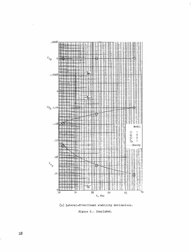
The longitudinal and lateral-directional stability derivatives are presented in figure 6. The circular-cone models yielded fair and good agreement with theory for the longitudinal and lateral-directional stability derivatives, respectively, whereas the elliptical-cone model showed excellent agreement in both the longitudinal and lateral-directional tests.
Figure 7 shows the variation of lift-drag ratio with angle of attack. For the circular-cone models, experimental values are generally somewhat lower than theoretical values over the test angle-of-attack range. At the higher angles of attack, the measured values were 7.5 percent lower than the theoretical values for model 1. The deviations for models 2, 3, and 4 never exceeded 5 percent over the angle-of-attack range. The elliptical-cone model 5 showed good agreement with theory despite the fact that the normal- and axial-force coefficients disagreed with theory as shown previously. In general, the trends of experimental lift-drag ratios are similar to those predicted by Newtonian theory.
Stability Limits for Complete Reentry Vehicle
For the complete reentry vehicle, which consists of a heat shield combined with an afterbody module, the longitudinal and lateral-directional stability limits can dictate center-of-gravity locations where (&, CnP, and C2P are equal to zero at a trim angle of attack of 0'. The afterbody module is assumed to be completely shielded from the flow and therefore contributes nothing to the aerodynamic characteristics of the reentry vehicle.
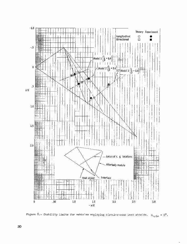
The theoretical and experimental stability limits are presented in composite form for models 1, 2, and 3 in figure 8. Unstable conditions exist when the center-of-gravityposition is rearward of the indicated stability limits. In general, the longitudinal limits based on experiment are in fair agreement with theory, whereas the directional limits were less accurately predicted. It is noted that, for each model, the experimental stability limits fall on or very near the theoretical locus of center-of-gravity locations which is a straight line normal to the skewed interface. The experimental data show that, as stated in reference 2, the directional limit is the deciding factor for the circular-cone configurations.
In figure 9, stability limits are presented for the elliptical-cone model 5 which has a lift-drag ratio of 0.6. Sizable differences occurred between the theoretical and experimental limits. It is noted that the theoretical and experimental longitudinal limits are in a position forward of the directional limits. Hence, the longitudinal limit dictates the center-ofgravity location for the elliptical-cone configuration, as concluded in reference 2. It is also seen that the experimental limits do not fall on the theoretical locus which for this model is not exactly normal to the interface.
For both the circular- and elliptical-cone configurations of this investigation, it appears that the extreme forward position of these stability limits can be realized only when the weight of the heat shield approximates or exceeds that of the afterbody module.
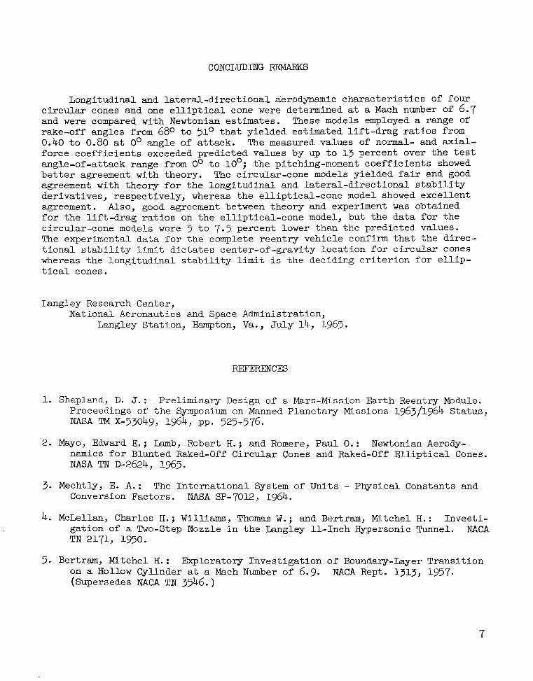
CONCLUDING REMARKS
Longitudinal and lateral-directionalaerodynamic characteristics of four circular cones and one elliptical cone were determined at a Mach number of 6.7 and were compared with Newtonian estimates. These models employed a range of rake-off angles from 680 to ?lo that yielded estimated lift-drag ratios from 0.40 to 0.80 at 0' angle of attack. The measured values of normal- and axial-force coefficients exceeded predicted values by up to 1.3 percent over the test angle-of-attack range from Oo to 10'; the pitching-moment coefficients showed better agreement with theory. The circular-cone models yielded fair and good agreement with theory for the longitudinal and lateral-directional stabilityderivatives, respectively, whereas the elliptical-cone model showed excellent agreement. Also, good agreement between theory and experiment was obtained for the lift-drag ratios on the elliptical-conemodel, but the data for the circular-cone models were 5 to 7.5 percent lower than the predicted values. The experimental data for the complete reentry vehicle confirm that the directional stability limit dictates center-of-gravity location for circular cones whereas the longitudinal stability limit is the deciding criterion for elliptical cones.
Langley Research Center, National Aeronautics and Space Administration,
Langley Station, Hampton, Va., July 14, 1965.
1. Shapland, D. J.: Preliminary Design of a Mars-Mission Earth Reentry Module. Proceedings of the Symposium on Manned Planetary Missions 1963/1964 Status, NASA TM X-53049, 1964,pp. 525-576.
2. Mayo, Edward E.; Lamb, Robert H.; and Romere, Paul 0 . : Newtonian Aerodynamics for Blunted Raked-Off Circular Cones and Raked-Off Elliptical Cones. NASA TN D-2624,1965.
3. Mechtly, E. A.: The International System of Units - Physical Constants and Conversion Factors. ' NASA SP-7Ol2, 1964.
4. McLellan, Charles H.; Williams, Thomas W.; and Bertram, Mitchel H.: Investigation of a Two-step Nozzle in the Langley ll-Inch IQ-personicTunnel. NACA TN 2171, 1950.
5. Bertram, Mitchel H.: Exploratory Investigation of Boundary-Layer Transition on a H o l l o w Cylinder at a Mach Number of 6.9. NACA Rept. 1313, 1957. (Supersedes NACA TN 3546.)
7
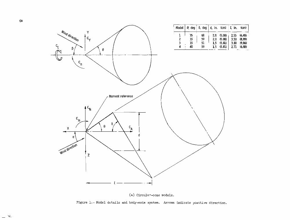
Model 0, deg 6, deg d, in. (cm)
1 35 68 2.0 (5.08)2 35 59 2.0 (5.08)3 35 51 1.5 (3.81)4 40 , 59 1 1.5 (3.81)
(a) Circular-cone models.
Figure 1.-Model de t a i l s and body-axis system. Arrows indicate posit ive direction.
2.55 (6.48)3.50 (8.89)3.88 (9.86)2.71 (6.88)

." .
M o d e l 1
.
M o d e l 2
. ~
M o d e l 3 M o d e l 4
Model 5
Figure 2.- Photographs of t e s t m o d e l s . L-65-160
10

M c d e l 1 M c d e l 2
M o d e l 3 M o d e l 4
M o d e l 5
Figure 3.- Schlieren photographs of models at a = 00. L-63-1-61
11
0
-.a
cm -1.6
-2.4
-3.2
2.5
2.0
1.5 I
C A
1.0
CN
.5'
0 2 4 6 8 1 0 0 2 4 6 8 1 0 a, 6% a, deg
Model 1 Model 2
(a) Circular-cone models.
Figure 4.- Longitudinal stability characteristics.
.12

0
-2
-4
-6
-a
-10
4
3 A
CN
2
1
0 2 4 6 8 1 0 a, deg
Model 3
(b) Circular-cone models..
Figure 4.-Continued.
C

-.2
-.6
. t
- 3
.2
(c) Elliptical-cone model.
Figure 4.-Concluded.
14

I
.2
0
-.2
-.4
-.6
-.8
0 2 4 6 a 10 8 , de@;
(a) Circular-cone models.
Figure 5.- Lateral-directional stability characteristics at a = Oo.

0
.04
.oa
.12
I 16
(b) Elliptical-cone model.
Figure 5.- Concluded.
16

0
-.Q8
-.16
-.24
-.32
.16
.12
.Q8
.Q4
0 50 54 58 62 66 0
deg
(a) Longitudinal stability derivatives.
Figure 6.- Summary of stability derivatives at a = Oo.
(b) Lateral-directional stability derivatives.
Figure 6.- Concluded.

0 Model 1 I 0 Model 20 Model 3 A Model 4 G Model 5
0 2 6
Figure 7.- Variation of lift-drag ratio with angle of attack for circular- and elliptical-cone models.
Longitudinal Directional
Theory Experiment
0 0 0 w
idel ...
z/d
/ of c. g. locations
1Afterbody module
0 .50 1.0 2.5 3.0
Figure 8.- S t a b i l i t y limits f o r vehicles employing circular-cone heat shields . a.trim = Oo.
x)

Theory Experiment
Longitudinal 0 e Direc t iona l 0 Latera i 0
-.25
0
Z/d
.75 0 * 75 1.001 1.25 1.50
-x/d
Figure 9.- StabLlity limits for a vehicle employing an elliptical-cone heat shield. atrFm = 00.
.21

“The aeronazitical and space activities of the United States shall be conducted so as to contribute . . . to the expansion of human knowledge of phenomena iz the atmosphere and space. The Administration shall provide for the widest practicable and appropriate dissemination of information concerning its actisities and the restilts thereof .”
-NATIONAL AND SPACEACTOF 1958AERONAUTICS
NASA SCIENTIFIC AND TECHNICAL PUBLICATIONS
TECHNICAL REPORTS: Scientific and technical information considered important, complete, and a lasting contribution to existing knowledge.
TECHNICAL NOTES: Information less broad in scope but nevertheless of importance as a contribution to existing knowledge.
TECHNICAL MEMORANDUMS: Information receiving limited distribution because of preliminary data, security classification, or other reasons.
CONTRACTOR REPORTS: Technical information generated in connection with a NASA contract or grant and released under NASA auspices.
TECHNICAL TRANSLATIONS: Information published in a foreign language considered to merit NASA distribution in English.
TECHNICAL REPRINTS: Information derived from NASA activities and initially published in the form of journal articles.
SPECIAL PUBLICATIONS: Information derived from or of value to NASA activities but not necessarily reporting the results .of individual NASA-programmed scientific efforts. Publications include conference proceedings, monographs, data compilations, handbooks, sourcebooks, and special bibliographies.
Details on the availability o f these publications may be obtained from:
SCIENTIFIC AND TECHNICAL INFORMATION DIVISION
NAT10NA L A E RONA UTICS A ND SPACE A DM I N I ST RATI 0N
Washington, D.C. PO546