Embed Size (px)
Citation preview
USB-SDP-CABLEZ User Guide UG-404
One Technology Way • P.O. Box 9106 • Norwood, MA 02062-9106, U.S.A. • Tel: 781.329.4700 • Fax: 781.461.3113 • www.analog.com
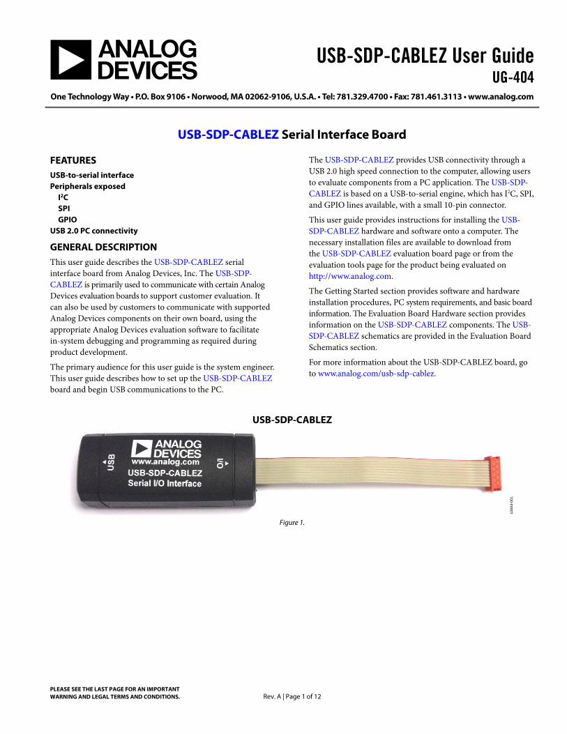
USB-SDP-CABLEZ Serial Interface Board
PLEASE SEE THE LAST PAGE FOR AN IMPORTANT WARNING AND LEGAL TERMS AND CONDITIONS. Rev. A | Page 1 of 12
FEATURES USB-to-serial interface Peripherals exposed
I2C SPI GPIO
USB 2.0 PC connectivity
GENERAL DESCRIPTION This user guide describes the USB-SDP-CABLEZ serial interface board from Analog Devices, Inc. The USB-SDP-CABLEZ is primarily used to communicate with certain Analog Devices evaluation boards to support customer evaluation. It can also be used by customers to communicate with supported Analog Devices components on their own board, using the appropriate Analog Devices evaluation software to facilitate in-system debugging and programming as required during product development.
The primary audience for this user guide is the system engineer. This user guide describes how to set up the USB-SDP-CABLEZ board and begin USB communications to the PC.
The USB-SDP-CABLEZ provides USB connectivity through a USB 2.0 high speed connection to the computer, allowing users to evaluate components from a PC application. The USB-SDP-CABLEZ is based on a USB-to-serial engine, which has I2C, SPI, and GPIO lines available, with a small 10-pin connector.
This user guide provides instructions for installing the USB-SDP-CABLEZ hardware and software onto a computer. The necessary installation files are available to download from the USB-SDP-CABLEZ evaluation board page or from the evaluation tools page for the product being evaluated on http://www.analog.com.
The Getting Started section provides software and hardware installation procedures, PC system requirements, and basic board information. The Evaluation Board Hardware section provides information on the USB-SDP-CABLEZ components. The USB-SDP-CABLEZ schematics are provided in the Evaluation Board Schematics section.
For more information about the USB-SDP-CABLEZ board, go to www.analog.com/usb-sdp-cablez.
USB-SDP-CABLEZ
1066
4-00
1
Figure 1.
UG-404 USB-SDP-CABLEZ User Guide
Rev. A | Page 2 of 12
TABLE OF CONTENTS Features .............................................................................................. 1 General Description ......................................................................... 1 USB-SDP-CABLEZ .......................................................................... 1 Revision History ............................................................................... 2 Product Overview ............................................................................. 3
Package Contents .......................................................................... 3 Technical or Customer Support.................................................. 3 Analog Devices Website .............................................................. 3
Getting Started .................................................................................. 4 PC Configuration ......................................................................... 4
USB Driver Installation ................................................................4 Adapter Boards ..............................................................................4 Powering Up/Powering Down the USB-SDP-CABLEZ...........5
Evaluation Board Hardware .............................................................6 LEDs ................................................................................................6 Connector Details .........................................................................6 Power...............................................................................................6
Evaluation Board Schematics...........................................................8 Bill of Materials ........................................................................... 11
REVISION HISTORY 7/12—Rev. 0 to Rev. A
Changes to Table 1 ............................................................................ 7 Changes to Power LED (LED3) Section and Figure 5 ................. 6
6/12—Revision 0: Initial Version
USB-SDP-CABLEZ User Guide UG-404
Rev. A | Page 3 of 12
PRODUCT OVERVIEW The USB-SDP-CABLEZ board includes the following:
• USB-to-serial engine • 1 × 10-pin connector
• AMP 10-way Micro-MaTch male connector • Peripherals exposed
• I2C • SPI • GPIO
PACKAGE CONTENTS The USB-SDP-CABLEZ board package contains the following:
• USB-SDP-CABLEZ serial interface • 1 m USB Standard-A-to-Mini-B cable • USB-I2C-ADPTZ adapter board (used to convert the
10-pin connector to a 3-pin I2C header)
Contact the vendor where the USB-SDP-CABLEZ board was purchased, or contact Analog Devices if anything is missing.
TECHNICAL OR CUSTOMER SUPPORT Analog Devices customer support can be reached in the following ways:
• Visit the EngineerZone® for community technical support at ez.analog.com.
• Phone questions to 1-800-ANALOGD • Contact your Analog Devices local sales office or
authorized distributor. • Send questions by mail to
Analog Devices, Inc. Three Technology Way P.O. Box 9106 Norwood, MA 02062-9106 USA
ANALOG DEVICES WEBSITE The Analog Devices website, www.analog.com, provides information about a broad range of products: analog integrated circuits, amplifiers, converters, and digital signal processors.
Also, note that MyAnalog.com is a free feature of the Analog Devices website that allows customization of a Web page to display only the latest information about products of interest to you. You can choose to receive weekly email notifications containing updates to the Web pages that meet your interests, including documentation errata for all documents. MyAnalog.com provides access to books, application notes, data sheets, code examples, and more.
Visit MyAnalog.com to sign up. If you are a registered user, simply log on. Your user name is your email address.

UG-404 USB-SDP-CABLEZ User Guide
Rev. A | Page 4 of 12
GETTING STARTED This section provides specific information to assist with using the USB-SDP-CABLEZ board as part of the user’s evaluation system.
The following topics are covered:
• PC configuration • USB installation • Powering up/powering down the USB-SDP-CABLEZ
PC CONFIGURATION For correct operation of the SDP board, the user’s computer must have the following minimum configuration:
• Windows XP Service Pack 2 or Windows Vista® • USB 2.0 port
When removing the USB-SDP-CABLEZ board from the package, handle the board carefully to avoid the discharge of static electricity, which can damage some components.
USB DRIVER INSTALLATION Perform the following tasks to correctly install the USB-SDP-CABLEZ driver software onto the computer. The software can be obtained from www.analog.com/usb-sdp-cablez and is called Common Run-Time Installer. Version 2.0.0 or greater is required to operate with the USB-SDP-CABLEZ.
Installing the Software
1. Run the setup.exe application found in the installer zip file. If running Windows XP, it may be necessary for the machine to restart shortly after the installation process begins.
2. The first part of the installer places the required Run-Time engine and software drivers for the USB-SMBUS-CABLE I2C dongle onto the PC.
3. After this, the installer for the USB-SDP-CABLEZ runs. As part of this, the .NET Framework 3.5 is installed, if not already on the PC. If the .NET Framework 3.5 is installed on the computer, this stage is skipped and only the driver package installation is installed.
Connecting the USB-SDP-CABLEZ Board to the PC
Attach the USB-SDP-CABLEZ board to a USB 2.0 port on the computer via the Standard-A-to-Mini-B cable provided.
Verifying Driver Installation
Before using the USB-SDP-CABLEZ board, verify that the driver software has installed properly.
Open the Windows Device Manager and verify that the USB-SDP-CABLEZ board appears under ADI Development Tools, as shown in Figure 2.
1066
4-00
2
Figure 2. Device Manager
ADAPTER BOARDS The USB-SDP-CABLEZ uses a 10-pin Micro-MaTch male connector as its interface connector. However, some older evaluation kits use a different connector for I2C connections and require the use of an adapter board to convert the 10-pin connector to an appropriate connection.
The USB-SDP-CABLEZ is supplied with the USB-I2C-ADPTZ adapter board to convert the 10-pin Micro-MaTch connector to a 3-pin 0.1" header connector.
1066
4-00
3
Figure 3. USB-I2C-ADPTZ Adapter Board
USB-SDP-CABLEZ User Guide UG-404
Rev. A | Page 5 of 12
The 10-way Micro-MaTch connector is fitted to the USB-I2C-ADPTZ board as shown in Figure 3, paying attention to the polarization of the Micro-MaTch connector (indicated by the red markings on the ribbon cable) and the key on the Micro-MaTch connector.
A USB-I2C5W-ADPTZ adapter board is also available, but is not supplied with the USB-SDP-CABLEZ. This board is only included in the specific evaluation kits that require it. It is connected to the Micro-MaTch connector in exactly the same way as the USB-I2C-ADPTZ.
1066
4-00
4
Figure 4. USB-I2C5W-ADPTZ Adapter Board
POWERING UP/POWERING DOWN THE USB-SDP-CABLEZ This section describes how to safely power up and power down the USB-SDP-CABLEZ.
Powering Up the USB-SDP-CABLEZ Board
1. Connect the USB-SDP-CABLEZ board to the evaluation board through the 10-pin mating connector, using an optional adapter if required.
2. Power up the evaluation board. 3. Connect the USB port on the computer to the USB-SDP-
CABLEZ board.
Powering Down the USB-SDP-CABLEZ Board
1. Disconnect the USB port on the computer from the USB-SDP-CABLEZ board.
2. Power down the daughter evaluation board. 3. Disconnect the USB-SDP-CABLEZ board from the
evaluation board.

UG-404 USB-SDP-CABLEZ User Guide
Rev. A | Page 6 of 12
EVALUATION BOARD HARDWARE This section describes the hardware design of the USB-SDP-CABLEZ board.
The following topics are covered:
• The LEDs section describes the USB-SDP-CABLEZ on-board LEDs.
• The Connector Details section details the pin assignments on the 10-pin connector.
• The Power section lists the power requirements of the USB-SDP-CABLEZ and identifies the connector power inputs and output pins.
LEDs There are three LEDs located on the USB-SDP-CABLEZ board (see Figure 5).
Power LED (LED3)
The green power LED indicates that the USB-SDP-CABLEZ board is powered up. This is not an indication of USB connectivity between the USB-SDP-CABLEZ and the PC.
1066
4-00
5
Figure 5. USB-SDP-CABLEZ Board LEDs
LED1
This yellow LED is currently not used in normal operation, but it may turn on when the board is initially connected to USB power.
LED2
The red LED is used as a diagnostic tool for evaluation application developers, usually to identify a particular board when more than one USB-SDP-CABLEZ is connected to a given PC.
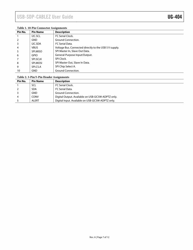
CONNECTOR DETAILS The USB-SDP-CABLEZ board provides one Micro-MaTch 10-way male connector. Through this connector, the peripheral communication interfaces of the USB-to-serial engine are exposed. The exposed peripherals are
• SPI • I2C • GPIO
Connector Pin Assignments
Table 1 lists the connector pins and identifies the functionality assigned to each connector pin on the USB-SDP-CABLEZ board.
POWER The USB-SDP-CABLEZ board is powered by the USB connector. Pin 4 (VBUS) of the 10-way connector is connected to the 5 V line of the USB connector, providing 5 V ± 10% as an output from the USB-SDP-CABLEZ board.
A small current can be drawn from this pin, but it should not be more than 20 mA to avoid potential problems with USB port current limiting.
USB-SDP-CABLEZ User Guide UG-404
Rev. A | Page 7 of 12
Table 1. 10-Pin Connector Assignments Pin No. Pin Name Description 1 I2C.SCL I2C Serial Clock. 2 GND Ground Connection. 3 I2C.SDA I2C Serial Data. 4 VBUS Voltage Bus. Connected directly to the USB 5 V supply. 5 SPI.MISO SPI Master In, Slave Out Data.
6 GPIO General-Purpose Input/Output.
7 SPI.SCLK SPI Clock. 8 SPI.MOSI SPI Master Out, Slave In Data. 9 SPI.CS.A SPI Chip Select A.
10 GND Ground Connection.
Table 2. 3-Pin/5-Pin Header Assignments Pin No. Pin Name Description 1 SCL I2C Serial Clock. 2 SDA I2C Serial Data. 3 GND Ground Connection. 4 CONV Digital Output. Available on USB-I2C5W-ADPTZ only. 5 ALERT Digital Input. Available on USB-I2C5W-ADPTZ only.
UG-404 USB-SDP-CABLEZ User Guide
Rev. A | Page 8 of 12
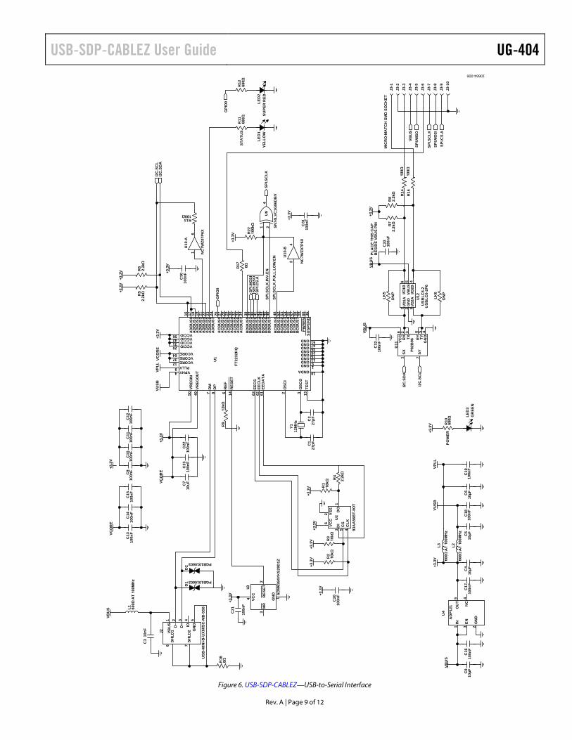
EVALUATION BOARD SCHEMATICS This section provides the schematic drawings for the following boards:
• USB-SDP-CABLEZ—USB-to-serial interface (see Figure 6). • USB-I2C-ADPTZ and USB-I2C5W-ADPTZ—adapter boards (see Figure 7).
USB-SDP-CABLEZ User Guide UG-404
Rev. A | Page 9 of 12
POW
ER
STA
TUS
SPI.S
CLK
.INV.
EN
SPI.S
CLK
.PU
LL.L
OW
.EN
PLA
CE
THIS
CA
PB
ESID
E VB
US
PIN
MIC
RO
-MA
TCH
SM
D S
OC
KET
50VR
EGIN
49VR
EGO
UT
7D
M8
DP
6R
EF14
RES
ET
63EE
CS
62EE
CLK
61EE
DA
TA
2O
SCI
3O
SCO
13TE
ST
16A
DB
US0
17A
DB
US1
18A
DB
US2
19A
DB
US3
21A
DB
US4
22A
DB
US5
23A
DB
US6
24A
DB
US7
26A
CB
US0
27A
CB
US1
28A
CB
US2
29A
CB
US3
30A
CB
US4
32A
CB
US5
33A
CB
US6
34A
CB
US7
38B
DB
US0
39B
DB
US1
40B
DB
US2
41B
DB
US3
43B
DB
US4
44B
DB
US5
45B
DB
US6
46B
DB
US7
48B
CB
US0
52B
CB
US1
53B
CB
US2
54B
CB
US3
55B
CB
US4
57B
CB
US5
58B
CB
US6
59B
CB
US7
60PW
REN
36SU
SPEN
D
56423120 VCCIO
VCCIOVCCIOVCCIO
643712 VCORE
VCOREVCORE
9 PLLV4 VPHY
51GND47GND35GND25GND15GND11GND5GND1GND
10GNDA
U1
FT22
32H
Q
D1 PGB1010603
D2
PGB1010603
R4
2.2k
Ω
R2
10kΩ
R3
10kΩ
R1
10kΩ
C1
27pF
C2
27pF
Y112
MH
z
R9
12kΩ
R16
0Ω
C3
10n
F
C21
100n
F
C22
100n
FC
2310
0nF
C20
100n
F
C9
100n
FC
1010
0nF
C11
100n
FC
1210
0nF
C13
100n
FC
1410
0nF
C15
100n
F
1IN
2G
ND
3EN
5O
UT
4N
C
U4
AD
P121
C16
100n
FC
1710
0nF
C18
100n
FC
1910
0nF
C4
10µF
R10
680Ω
R6
2.2k
ΩR
52.
2kΩ
1VB
US
2D
–3
D+
4IO
5G
ND
6SH
LD1
7SH
LD2J2
USB
-MIN
I-B-U
X60S
C-M
B-5
S8L1 600Ω
AT
100M
Hz
L3
600Ω
AT
100M
Hz
600Ω
AT
100M
Hz
L2
1GN
D
2R
ESET
3M
R
4 VCC
U3
AD
M63
84YK
S29D
1Z
LED
3G
REE
N
LED
1YE
LLO
W
R22
100k
Ω 1 24
U9
SN74
LVC
1G86
DB
V
R12
680Ω
R11
680Ω
C30
100n
F
C31
100n
F
16
U10
-A
NC
7WZ0
7P6X
34
U10
-B
NC
7WZ0
7P6X
R13100Ω
1SX
7SY
5TY
6R
Y
3TX
2R
X8
VCC
4G
ND
U11
P82B
96
C32
100n
F
1I/O
1A2
GN
D3
I/O2A
4I/O
2B5
VBU
S6
I/O1B
U12
USB
LC6-
2U
SBLC
6-2P
6
C33
100n
FR
82.
2kΩ
R7
2.2k
Ω
R14
100Ω
R15
100Ω
LED
2SU
PER
RED
C5
10µF
C6
10µF
C8
10µF
C7
10uF
1D
O
2 VSS
3D
I6 VCC
5C
S4
CLK
U2
93A
A56
BT-
I/OT
J3-1
J3-2
J3-3
J3-4
J3-5
J3-6
J3-7
J3-8
J3-9
J3-1
0
LK5
DN
P
DN
P
LK6
R17 0Ω
I2C
.SC
LI2
C.S
DA
SPI.M
OSI
SPI.M
ISO
SPI.C
S.A
VCO
RE
+3.3
V
+3.3
V+3
.3V
+3.3
V+3
.3V
+3.3
V
VBU
S
+3.3
V
VUSB
VPLL
VCO
RE
+3.3
V
+3.3
V
VCO
RE
VBU
S
+3.3
VVU
SBVP
LL+3
.3V
+3.3
V+3
.3V
SPI.S
CLK
GPI
O0
+3.3
V
I2C
.SD
A
I2C
.SC
L
VBU
SVB
US
+3.3
V
+3.3
V
+3.3
V
VBU
SSP
I.MIS
O
SPI.S
CLK
SPI.M
OSI
SPI.C
S.A
GPI
O0
10664-006
Figure 6. USB-SDP-CABLEZ—USB-to-Serial Interface

UG-404 USB-SDP-CABLEZ User Guide
Rev. A | Page 10 of 12
10-WAY MICRO-MATCHCONNECTOR
10-WAY 2 × 5 WAYDIL 0.1" HEADER
3- OR 5-WAY 0.1" HEADER
J1-1
J1-2
J1-3
J1-4
J1-5
J1-7
J1-8
J1-9
J1-10
J2-1
J2-2
J2-3
J2-4
J2-5
J2-6
J2-7
J2-8
J2-9
J2-10
J1-6
J3-1
J3-2
J3-3
J3-4
J3-5
I2C.SCL
GND
I2C.SDA
VBUS
SPI.MISO
SPI.SCLK
SPI.MOSI
SPI.CS.A
GND
GND
GND
GND
I2C.SCL
I2C.SDA
GND
GPIO1
SPI.MISO
GPIO1
1066
4-00
7
Figure 7. USB-I2C-ADPTZ and USB-I2C5W-ADPTZ—Adapter Boards
USB-SDP-CABLEZ User Guide UG-404
Rev. A | Page 11 of 12
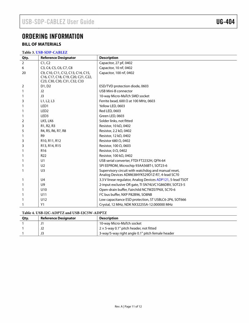
ORDERING INFORMATION BILL OF MATERIALS
Table 3. USB-SDP-CABLEZ Qty. Reference Designator Description 2 C1, C2 Capacitor, 27 pF, 0402 6 C3, C4, C5, C6, C7, C8 Capacitor, 10 nF, 0402 20 C9, C10, C11, C12, C13, C14, C15,
C16, C17, C18, C19, C20, C21, C22, C23, C30, C30, C31, C32, C33
Capacitor, 100 nF, 0402
2 D1, D2 ESD/TVD protection diode, 0603 1 J2 USB Mini-B connector 1 J3 10-way Micro-MaTch SMD socket 3 L1, L2, L3 Ferrite bead, 600 Ω at 100 MHz, 0603 1 LED1 Yellow LED, 0603 1 LED2 Red LED, 0603 1 LED3 Green LED, 0603 2 LK5, LK6 Solder links, not fitted 3 R1, R2, R3 Resistor, 10 kΩ, 0402 5 R4, R5, R6, R7, R8 Resistor, 2.2 kΩ, 0402 1 R9 Resistor, 12 kΩ, 0402 3 R10, R11, R12 Resistor 680 Ω, 0402 3 R13, R14, R15 Resistor, 100 Ω, 0603 1 R16 Resistor, 0 Ω, 0402 1 R22 Resistor, 100 kΩ, 0402 1 U1 USB serial converter, FTDI FT2232H, QFN-64 1 U2 SPI EEPROM, Microchip 93AA56BT-I, SOT23-6 1 U3 Supervisory circuit with watchdog and manual reset,
Analog Devices ADM6384YKS29D1Z-R7, 4-lead SC70 1 U4 3.3 V linear regulator, Analog Devices ADP121, 5-lead TSOT 1 U9 2-input exclusive OR gate, TI SN74LVC1G86DBV, SOT23-5 1 U10 Open-drain buffer, Fairchild NC7WZ07P6X, SC70-6 1 U11 I2C bus buffer, NXP P82B96, SO8NB 1 U12 Low capacitance ESD protection, ST USBLC6-2P6, SOT666 1 Y1 Crystal, 12 MHz, NDK NX3225SA-12.000000 MHz
Table 4. USB-I2C-ADPTZ and USB-I2C5W-ADPTZ Qty. Reference Designator Description 1 J1 10-way Micro-MaTch socket 1 J2 2 × 5-way 0.1" pitch header, not fitted 1 J3 3-way/5-way right angle 0.1" pitch female header

UG-404 USB-SDP-CABLEZ User Guide
Rev. A | Page 12 of 12
I2C refers to a communications protocol originally developed by Philips Semiconductors (now NXP Semiconductors).
ESD Caution ESD (electrostatic discharge) sensitive device. Charged devices and circuit boards can discharge without detection. Although this product features patented or proprietary protection circuitry, damage may occur on devices subjected to high energy ESD. Therefore, proper ESD precautions should be taken to avoid performance degradation or loss of functionality.
Legal Terms and Conditions By using the evaluation board discussed herein (together with any tools, components documentation or support materials, the “Evaluation Board”), you are agreeing to be bound by the terms and conditions set forth below (“Agreement”) unless you have purchased the Evaluation Board, in which case the Analog Devices Standard Terms and Conditions of Sale shall govern. Do not use the Evaluation Board until you have read and agreed to the Agreement. Your use of the Evaluation Board shall signify your acceptance of the Agreement. This Agreement is made by and between you (“Customer”) and Analog Devices, Inc. (“ADI”), with its principal place of business at One Technology Way, Norwood, MA 02062, USA. Subject to the terms and conditions of the Agreement, ADI hereby grants to Customer a free, limited, personal, temporary, non-exclusive, non-sublicensable, non-transferable license to use the Evaluation Board FOR EVALUATION PURPOSES ONLY. Customer understands and agrees that the Evaluation Board is provided for the sole and exclusive purpose referenced above, and agrees not to use the Evaluation Board for any other purpose. Furthermore, the license granted is expressly made subject to the following additional limitations: Customer shall not (i) rent, lease, display, sell, transfer, assign, sublicense, or distribute the Evaluation Board; and (ii) permit any Third Party to access the Evaluation Board. As used herein, the term “Third Party” includes any entity other than ADI, Customer, their employees, affiliates and in-house consultants. The Evaluation Board is NOT sold to Customer; all rights not expressly granted herein, including ownership of the Evaluation Board, are reserved by ADI. CONFIDENTIALITY. This Agreement and the Evaluation Board shall all be considered the confidential and proprietary information of ADI. Customer may not disclose or transfer any portion of the Evaluation Board to any other party for any reason. Upon discontinuation of use of the Evaluation Board or termination of this Agreement, Customer agrees to promptly return the Evaluation Board to ADI. ADDITIONAL RESTRICTIONS. Customer may not disassemble, decompile or reverse engineer chips on the Evaluation Board. Customer shall inform ADI of any occurred damages or any modifications or alterations it makes to the Evaluation Board, including but not limited to soldering or any other activity that affects the material content of the Evaluation Board. Modifications to the Evaluation Board must comply with applicable law, including but not limited to the RoHS Directive. TERMINATION. ADI may terminate this Agreement at any time upon giving written notice to Customer. Customer agrees to return to ADI the Evaluation Board at that time. LIMITATION OF LIABILITY. THE EVALUATION BOARD PROVIDED HEREUNDER IS PROVIDED “AS IS” AND ADI MAKES NO WARRANTIES OR REPRESENTATIONS OF ANY KIND WITH RESPECT TO IT. ADI SPECIFICALLY DISCLAIMS ANY REPRESENTATIONS, ENDORSEMENTS, GUARANTEES, OR WARRANTIES, EXPRESS OR IMPLIED, RELATED TO THE EVALUATION BOARD INCLUDING, BUT NOT LIMITED TO, THE IMPLIED WARRANTY OF MERCHANTABILITY, TITLE, FITNESS FOR A PARTICULAR PURPOSE OR NONINFRINGEMENT OF INTELLECTUAL PROPERTY RIGHTS. IN NO EVENT WILL ADI AND ITS LICENSORS BE LIABLE FOR ANY INCIDENTAL, SPECIAL, INDIRECT, OR CONSEQUENTIAL DAMAGES RESULTING FROM CUSTOMER’S POSSESSION OR USE OF THE EVALUATION BOARD, INCLUDING BUT NOT LIMITED TO LOST PROFITS, DELAY COSTS, LABOR COSTS OR LOSS OF GOODWILL. ADI’S TOTAL LIABILITY FROM ANY AND ALL CAUSES SHALL BE LIMITED TO THE AMOUNT OF ONE HUNDRED US DOLLARS ($100.00). EXPORT. Customer agrees that it will not directly or indirectly export the Evaluation Board to another country, and that it will comply with all applicable United States federal laws and regulations relating to exports. GOVERNING LAW. This Agreement shall be governed by and construed in accordance with the substantive laws of the Commonwealth of Massachusetts (excluding conflict of law rules). Any legal action regarding this Agreement will be heard in the state or federal courts having jurisdiction in Suffolk County, Massachusetts, and Customer hereby submits to the personal jurisdiction and venue of such courts. The United Nations Convention on Contracts for the International Sale of Goods shall not apply to this Agreement and is expressly disclaimed.
©2012 Analog Devices, Inc. All rights reserved. Trademarks and registered trademarks are the property of their respective owners. UG10664-0-7/12(A)