Embed Size (px)
Citation preview

IqL1-(RLt.
g^COMMONWEALTH OF AUSTRALIA
DEPARTMENT OF NATIONAL DEVELOPMENT
BUREAU OF MINERAL RESOURCES, GEOLOGY AND GEOPHYSICS
RECORD No. 1964/84
1 BUTtgA13' or 11m4'EltAL EMITZEICESi GEOFUYSICAL LIT:DifiY
°I857° 1 ka..............B^1
TALLEBUNG GEOPHYSICALSURVEY FOR ALLUVIAL TIN,
NSW 1961-1962
BY
Md. O'CONNOR and R.J. SMITH
The information contained in this report has been obtained bythe Department of National Development as part of the policyof the Commonwealth Government to assist in the explorationand development of mineral resources. It may not be publishedin any form or used in a company prospectus or statement withoutthe permission in writing of the Director, Bureau of MineralResources, Geology and Geophysics.

RECORD No. 1964/84
1 BUREAU OF hill4r1:A1.14.11:14117,1',CFB
i GEOt i l\r8 lICAL LITRONi - lig1^.........._. • ...... ..
TALLEBUNG GEOPHYSICALSURVEY FOR ALLUVIAL TIN,
NSW 1961-1962
10.1. OTONNOR and Rd. SMITE
The information contained in this report has been obtained bythe Department of National Development as part of the policyof the Commonwealth Government to assist in the explorationand development of mineral resources. It may not be publishedin any form or used in a company prospectus or statement withoutthe permission in writing of the Director, Bureau of MineralResources, Geology and Geophysics.
"4.1.

CONTENTS
Page
- . SUMMARY
1 • INTRODUCTION
2. GEOLOGY 1
3. METHODS & EQUIPl\ffiNT 2
• 4: • FIELD WORK AND RESULTS 3
5. INTERPRE'}ATION OF RESULTS 6
6. CONCLUSIONS AND RECO~~~ATIONS 10
7. REFERENCES 11
ILLUSTRATIONS :>
Plate 1 • Traverse and locality plans (Drawing No.I55/B7-11)
• J Plate 2. Seismic cross-sections, Traverses 00 to 3000N (I55/B7-15)
Plate 3, S,,:l:i .. smic cross-sections, Traverses A to F (I55/B7-12)
Plate 4. Seismic cross-sections, Traverses G, E, and Z (I55/B7-13)
Plate 5. Bedrock contours (from seismic data) (I55/B7-1O)
Plate 6. Bedrock gravity contours (I55/B7-14)
Plate 7 • Residual gravity contours (I55/B7-8)
.. ..

SIIIMARY
Geophysical surveys were made at Tallebung, NSW in 1961and 1962.^Several deep leads of alluvial tin had been extensivelymined and drilled there and had been shown to lie beneath thealluvium in depressions in the slate bedrock. The aim of thesurveys was to trace the main depression beyond the known area byusing several geophysical mezhods.
The 1961 survey consisted mainly of the seismic refractionmethod with some magnetic and resistivity work. A smaller partymade a short gravity survey in 1962. The seismic and gravity methodsproved useful and it was possible to predict the probable course ofthe lead for several miles. Resistivity and magnetic results werenot useful for detecting bedrock depressions and are not included inthis report.
Some preliminary drilling was done during the survey anathe results were used in the interpretation of the geophysical work.Sev,2al additional drill sites are recommended. .
-

r'.
1. INTRODUCTION
The Tallebung tinfield is situated 46 miles by road north-westerly from Condobolin (339 miles from Sydney on the Broken Hillrailway) in the Parish of Urambie East, Country of Blaxland, NSW.
Tin was first reported from this locality in 1880 andsince then both reef and alluvial tin have been worked. However,owing to many causes, such as lack of water and the low price oftin, mining was only carried on intermittently.
In 1961 the Tuflabong Tin Syndicate Ltd was engaged indrilling and sampling two tin leads at Tallebung. This testing andthe old alluvial mining had been concentrated mainly near the sourceof the tin. The NSW Mines Department requested a geophysicalsurvey by the Bureau of Mineral Resources, Geology and Geophysicsto assist in tracing the leads from where they were known to thebroad flats north of the worked area.
The geophysical field work in 1961 occupied 16 weeksfrom 17th July to 6th November.^Seismic, refraction, magnetic,and resistivity methods were used. The geophysical party consistedof geophysicists, M.J. O'Connor (party leader), R.J. Smith, andF. Maranzana, five field assistants, and a cook. The topographicalsurvey of the travers lines was carried out by surveyor J.P. Dynesof the Department of the Interior, Sydney, assisted by two chainmen.Owing to illness, Mr-Dynes was relieved near the end of the surveyby surveyor A.N. Rochfort.
Early in 1962 it was decided to use the gravity methodin the area to gain additional information, which it was hopedwould help in the interpretation of the geophysical work done inthe previous year.^Geophysicists R.J. Smith and J.P. Williamsand field assistant N. Ashmore macb.agravity survey between 4th and17th April 1962.
2. GEOLOGY
The geology of the Tallebung tinfield has been describedby Carne (1911) and Raggatt (1939).^The following notes are basedon Raggatt's report.
The country rock in the tinfield consists of Ordoviciansediments, mainly dark grey to black slates, with occasional thinwhite sandy bands. The regional strike is N30°W, and the dipgenerally west at 50 to 70 degrees.^The sediments have beenintruded on a large scale by the Erimeran granite, which coverslarge areas to the north, north-west, and south of Tallebung.The nearest outcrop of granite is about 1irmiles south of thetinfield.
Outcrop is confined to scattered ranges of low hills,surrounded by extensive soil flats. The sediments contain quartzreefs, carrying cassiterite and wolfram.^It is noticeable thatthe granite in the immediate neighbourhood of Tallebung contains notin, although the Erimeran granite is known to carry tin mineral-isation in several other areas.

Geophysicalmethod
Instrument
Seismic^Portable refractionseismograph
Geophones.
2.
Although a considerable amount of tin has been producedfrom small workings on the quartz reefs, the main reserves arecontained in alluvial deposits. Old drainage channels under thealluvial flats contain cassiterite derived from the weathering ofthe reefs, and in several areas, these form deposits of high grade.Three such leads are known, and are referred to as the Southern,Central, and Northern leads (Plate 1).^The first alluvial miningwas at a depth of about 28 ft; however, this lead was on a falsebottom and in 1937 deeper leads were found at depths of about 60 ft.The field is in an area of low and unreliable rainfall, and mininghas been frequently hampered by shortage of water. For this andother reasons, previous mining has been selective, confined to high-grade ore. Construction of a pipe line from the Lachlan River hasnow provided an assured water supply which will enable large-scalesystematic mining to be carried out.
3. METHODS AND EQUIPMENT
The geophysical methods used in the Tallebung survey wereseismic refraction, magnetic, resistivity, and gravity.^Theapplicability of these methods to the problem of detecting alluvialdeposits has been discussed by Sedmik (1964).
The geophysical equipment used on the surveys consistedof:
Manufacturer^Type
SIE^PRO-11-6°
Electro-Tech 20 c/s
Magnetic^Torsion magnetometer^
ABM^
Model 4,(vertical force)^
Ser.No.4503
Resistivity
Gravity
Geophysical megger
Resistivity meter
Tellohm meter
Gravity meter
Evershed &Vignoles
Bureau ofMineralResources
Nash &ThompsonLtd
World WideInstrumentInc.
0-30 ohm
Type ASer. No.2
Model G.P.Ser. No.144
Ser. No35

3.
4.. FIELD WORK AND RESULTS
The complete geophysical grid is shown in Plate 1.Its origin is on the north-west corner of EL12.^Traverses 0 to3000N, which are parallel and spaced 500 ft apart, run roughly east. ,
west.
The seismic results along these traverses proveddifficult to interpret.^It was thought that these difficultiesmight be caused by the fact that in this area the traverses crossedthe general strike of the slates and quartzites which have undergonevarying degrees of weathering. It was decided to change thedirection of the traverses and to work back from a gap in the hillsnorth-east of Tallebung towards Traverse 3000N (see Plate 1).
Traverse A was laid down across the gap and TraverseB was set parallel to Traverse A and 500 feet away. Traverses C I
D I E, and F were then placed parallel to Traverse B and separated by100Dft.^These traverses are roughly parallel to the regional strikeof the rocks.^Two traverses, viz. Traverses G and H, were placedbetween Traverses F and 3000N as shown in Plate 1. Traverse Z wasrun perpendicular to Traverse B from B5000N.
The total length of traverses covered by the seismicmethod was 14 miles.^The seismic work consisted of:
(a) Weathering spreads to obtain the seismic wavevelocities in the soil and near-surface layers.Geophones were spaced at 5 and 10-ft intervalsand shot-points were placed in line with the spreadat distances of 5 ft, 50 ft, and in places up to150 ft, from each end of the spread,
(b) Normal spreads to determine the time taken for thewaves to travel from the surface to the bedrock andback to the surface and also to measure the velocitiesin the formations beneath the soil.^Geophones inthese spreads were spaced at 50-ft intervals and theshot-points were placed in line with the spread atdistances ranging from 25 ft to 1000 ft from either endof the spread.
It was found after some experimental shooting atTallebung that calculation of a continuous profileof the bedrock from the seismic results requiredconsiderable over-lap of geophone spreads. Themost suitable over-lap was found to be 250 or 300ft.
(c) Borehole and shaft velocity logging to measuredirectly the average seismic velocity (verticaldirection) in the overburden between the shot-point and the surface.^Shots were fired inboreholes and shafts and times were measured togeophones on the surface near the collar of theholes or shafts.^Shots were generally placedat the bottom of, and at regular intervals up,each borehole or shaft.
fo

.1•
4.
Vertical travel times (VTT) were computed at eachgeophone station for normal spreads by using the method of differences,The VTT were converted to depths using the mean time/depth curvederived from the results of the shots at various depths in the bore-holes and shafts. A correction was applied to compensate forvariations in the thickness of the low-velocity surface layer. Anaverage velocity of 1000 ft/sec was assumed for this layer, based onthe measurements with weathering spreads.
These results are shown as solid lines on the seismiccross-section of Plates 2, 3, and 4 and the bedrock contours derivedfrom them are shown in Plate 5. Depth estimates were also madeusing the intercept times and the standard method of computingdepths to various refractors (Hawkins, 1961).^This was done where7erpossible and the results, together with the velocities used in thecomputations, are also shown in Plates 2, 3, and 4 for comparison withthe results from the time/depth curves.
Gravity
Gravity measurements were made on setsmic Traverses1000N, 3000N, H, G, F, D, B, A, and Z, and on one new traverse(Traverse X) which was pegged and levelled by the geophysical party.Altogether 44,000 ft of traverse were surveyed with the gravitymeter.
The area is flat and easily accessible by Land-Roverso that one main base (D4200N) and one sub-base (3000N/1200W)provided sufficient control over the whole area. Most traverseswere surveyed at 100-ft intervals between observation points butsome measurements were made at 50-ft intervals in interesting areas.Readings were taken at either'the main base or the sub-base approx-imately every hour and several checkpoints were also read at shortintervals along the traverse in order to have sufficient controlover the drift of the instrument. On several occasions where asteep or irregular drift was observed, readings were repeated onanother day.
Samples were taken of the overburden, and the weathered.and unweathered bedrock for density measurements. The mean densityof unweathered bedrock was determined at 2.6+9.1 g/cm^Samples ofoverburden were taken about 1 ft below the surface to avoid topsoileffects (loose pebbles, grass roots, etc.) but the density determin-ations of these samples showed a considerable range of values andcould not be regarded as reliable.^It was decided to adopt adensity of 2.0 g/cm3 for the overburden.
The gravity results were corrected for instrumentaldrift, elevation, and latitude; a Bouguer anomaly profile wasdrawn for each traverse. The profiles were then used to drawa Bouguer anomaly contour map. The contour map showed littleevidence of a depression going through the area and did not appearto be consistent with drilling results.
It was reasonable to expect that the deeper geologicalstructure would have some effect on the gravity results and thiswas particularly evident on Traverses 1000N and 3000N where agravity 'high' coincided with the position of the lead as shown bydrilling. The most important part of the gravity interpretationwas the separation of the effect of the old river valley from the.effect of variations in density of the bedrock and regional gravityvariations.

5.
In order to separate the two effects it was firstnecessary to construct a gravity map (referred to as a 'bedrock'gravity map) which was not affected by the presence of the old rivervalley. Points near outcrop or known shallow bedrock wereselected from the Bouguer contour map and used as a basis for thebedrock gravity contour map. Additional information was obtainedfrom boreholes and shafts throughout the area. Where the depthto bedrock was known, the effect of that thickness of overburdencould be calculated (assuming a density contrast of 0.5 gicm 3between overburden and bedrock) and removed from the elevation-corrected gravity at that point. This gave several additionalpoints on the gravity map and a contour map was drawn using allsuch available information (Plate 6). The difference between theBouguer contour map and the bedrock gravity map should then be dueto the presence of the old river valley; a residual gravity mapshould indicate the course of the valley.^It must be emphasisedthat the borehole data, which it has been necessary to use toobtain most of the bedrock gravity values, may not be reliablewith regard to depth to bedrock. If these borehole data are notreliable an error is introduced. The complex nature of thebedrock gravity data also limits the accuracy of the gravityinterpretation. Between Traverses A and F the bedrock. gravitycontours are simple and regular but they become increasinglycomplex towards the southern part of the area.^It is not possibleto map accurately such a complex field with the few scatteredpoints available and for this reason Traverse 1000N has beenomi-,ted from the bedrock and residual gravity maps.
The bedrock gravity values (Plate 6) were subtractedfrom the Bouguer gravity values to give the residual gravity valueswhich were contoured (Plate 7). This residual gravity map shouldshow the position of the old river valley and the value of residualgravity should be roughly proportional to the depth to bedrock.This estimate of depth should be more accurate over the lead thanover shallow bedrock as the elevation corrections (based on adensity of 2.0 g/cm3 ) should be more appropriate over the lead.
The residual gravity map shows a main depressionthat can be traced through the whole surveyed area with severalpossible tributaries.^Generally the residual gravity contoursshow a close resemblance to the bedrock contours derived fromseismic work, but with some minor differences that will be discussedlater.
Magnetic
Magnetic readings were made along Traverses 00, 500N,and 1000N at 50-ft intervals except between 1600W and 300W alongTraverse 500N where readings were taken at 25-ft intervals.
Resistivity_
Using the Wenner configuration of electrodes, thefollowing resistivity work was done:
Depth probes
Depth probes were made at five boreholes in the southernpart of the area.

•
6.
,Constant electrode spacing
Traverse^Electrode^spacing(ft)
^
740S^ 50
00^ 50
^
500N^ 100
^
1000N^ 50
^
2500N^ 50,100
A^ 100
A larger electrode spacing than actually used wouldhave been desirable but the low resistivity values encountered didnot permit use of 150 and 200-ft spacings which would have beenmore appropriate for the thickness of overburden in this area.
5. INTERPRETATION OF RESULTS
Seismic
The seismic velocities measured during the survey atTallebung may be classified into four groups as follows:
.4.^ Group Lonitudinal velocity Rock typift5-e-0----
1 500 - 1500 Top soil
2 2500 - 6000 Alluvium
3 5500 - 12,000 Weathered slate
4 12,000 7 17,000 Slightly weatheredto unweatheredslate.
The leads have been shown by mining and drilling tolie under the alluvium in old river channels or depressions in thesoft slate bottom.^The measured seismic velocities in theweathered and fresh slate vary markedly along each traverse (seePlates 2, 3, and 4), probably owing to variations in the degree ofweathering and also in the thickness and frequency of bands ofquartzite that occur in the slate. The velocities measured in theweathered and unweathered bedrock were generally greatest in thestriking direction of the beds, i.e. the velocities measured alongTraverses A, B, C, D, E, and F (which were laid out parallel tothe general striking direction of the country rocks) were in generalgreater than the velocities measured along the Traverses 00 to 3000,G, H9 and Z.
7
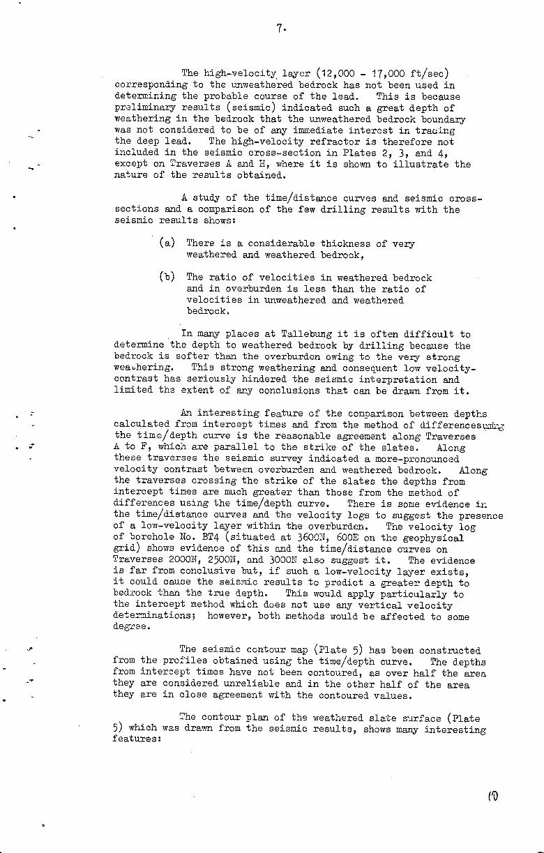
The high-velocity . layer (12,000 - 17,000 ft/sec)corresponding to the unweathered bedrock has not been used indetermining the probable course of the lead. This is becausepreliminary results (seismic) indicated such a great depth ofweathering in the bedrock that the unweathered bedrock boundarywas not considered to be of any immediate interest in tractingthe deep lead. The high-velocity refractor is therefore notincluded in the seismic cross-section in Plates 2, 3, and 4,
"a.
^
^ except on Traverses A and H, where it is shown to illustrate thenature of the results obtained.
A study of the time/distance curves and seismic cross-sections and a comparison of the few drilling results with theseismic results shows:
(a) There is a considerable thickness of veryweathered and weathered bedrock,
(b) The ratio of velocities in weathered bedrockand in overburden is less than the ratio ofvelocities in unweathered and weatheredbedrock.
In many places at Tallebung it is often difficult todetermine the depth to weathered bedrock by drilling because thebedrock is softer than the overburden owing to the very strongweaalering. This strong weathering and consequent low velocity-contrast has seriously hindered the seismic interpretation andlimited the extent of any conclusions that can be drawn from it.
An interesting feature of the comparison between depthscalculated from intercept times and from the method of differeneese
• the time-:/depth curve is the reasonable agreement along Traverses• A to F, which are parallel to the strike of the slates.^Along
these traverses the seismic survey indicated a more-pronouncedvelocity contrast between overburden and weathered bedrock. Alongthe traverses crossing the strike of the slates the depths fromintercept times are much greater than those from the method ofdifferences using the time/depth curve. There is some evidence inthe time/distance curves and the velocity logs to suggest the presenceof a low-velocity layer within the overburden. The velocity logof borehole No. BT4 (situated at 3600N, 600E on the geophysicalgrid) shows evidence of this and the time/distance curves onTraverses 2000N, 2500N, and 3000N also suggest it. The evidenceis far from conclusive but, if such a low-velocity layer exists,it could cause the seismic results to predict a greater depth tobedrock than the true depth. This would apply particularly tothe intercept method which does not use any vertical velocitydeterminations; however, both methods would be affected to somedegree.
The seismic contour map (Plate 5) has been constructedfrom the profiles obtained using the time/depth curve.^The depthsfrom intercept times have not been contoured, as over half the areathey are considered unreliable and in the other half of the areathey are in close agreement with the contoured values.
The contour plan of the weathered slate surface (Plate5) which was drawn from the seismic results, shows many interestingfeatures:

0. 1
.*
8.
(a) In the weathered slate surface a depression isindicated that can be traced from Traverse 00through to the other end of the surveyed areaat Traverse A.^It appears likely that themain deep lead at Tallebung is associated with thisdepression which runs roughly north-westerly fromTraverse 00 to Traverse 2000N where its directionswings around to northerly; the direction fromTraverse 3000N to Traverse F is north-easterly.East of Traverse F the direction of the indicateddepression swings more to the north and followsa slightly sinuous course through to Traverse A,
(b) This main depression has a gentle fall fromTraverse 00 to Traverse 2500N, is relatively flatbetween Traverses 2500N and H, and then there isa steeper downward gradient between Traverses Hand G. Between Traverses G and A the indicateddepression remains relatively flat,
(c) Two minor depressions coming from the north-westbetween Traverses E and A cross Traverse Z.^Thesedepressions, which probably combine with the maindepression between Traverse B and D, come from arelatively short valley between two lines of hillsand are not considered to be of any importance astin prospects,
(d) A large depression coming from the south-east runsalong Traverse D.^It probably joins the maindepression between Traverses D and E. There isno reason to expect this depression is tin-bearingas no primary tin deposits are known in the bedrockoutcrops in the neighbourhood,
(e) A small, shallow depression cuts across the easternends of Traverses 500N, 1000N, and 2000N.^Thisdepression runs slightly west of north and is knownfrom mining and drilling to carry low tin values.It probably joins the main depression betweenTraverses G and H,
(f) A ridge in the weathered slate along Traverse Eis probably associated with the slate hills betweenTraverses G and F.
Gravit/
The bedrock gravity map (Plate 6), based largely onborehole data, shows some surprising features. North of TraverseG the bedrock gravity contours Aare regular and evenly spaced but,in the southern part of the area, between Traverses G and 1000N,the bedrock, gravity contours show relatively steep gradients andirregular shapes. The most significant feature of this map is thesteep bedrock gravity gradient between the eastern ends of TraversesG and 3000N. Although this is based on a few widely scatteredpoints, the values have been carefully checked and there is littledoubt that the steep gradient really exists.^This feature couldbe caused by the presence of a fault zone which, if it continues tothe west, could also explain a steep gradient between the westernends of Traverses 3000N and H.

9.
Between Traverses 3000N and 1000N very little data onthe bedrock gravity gradient. is available. The available informat-ion indicates a steep, regular gradient but Traverse 1000N wasdisregarded because of insufficient data. North of Traverse Gthere were no peculiarities and the bedrock gravity values shouldbe reliable.
The residual gravity map (Plate 7), obtained by subtract-ing the bedrock gravity values from the observed values, shows ageneral similarity with the seismic contour map (Plate 5). The maimgravity depression could be traced through the area from Traverse3000N to Traverse A following a similar course with some deviations,to the bedrock depression indicated by the seismic survey. Bothgeophysical methods indicate a generally broad and poorly defineddepression. As few traverses were used to cover a large area,especially with the gravity method, contouring involved considerableinterpolation.
The main residual-gravity depression intersects Traverses3000N, H, F, and A at the same points as the bedrock depression shownon the seismic contour map. There are discrepancies on TraversesG, D, and B but only on Traverse D is the discrepancy large.
On Traverse G the gravity depression is about 500 ft eastof the seismic depression.^The depression there is not well defined.by either method (seismic or gravity) so further drilling would beneeded to position the lead there.
The main difference between the two maps (seismic andresidual gravity) is the position of the depression on Traverse D.The seismic work indicates a broad, poorly-defined bedrockdepression at about 2000N where there is a slight residual gravity'high'.^The seismic and gravity profiles are both relatively flatand it seems unlikely that the difference between the two methodscan be resolved.
The gravity depression on Traverse B is narrow and well-defined at 3900N which is 400 ft away from the seismic depressionindicated at 4300N.^The seismic depression is less well-definedand the difference in location can easily be attributed to experimentalerror.
The residual gravity contours show a basin-likedepression on the main lead between Traverses H and G, correspondingto a sharp change in gradient of the bedrock indicated on the •seismic map.^The part of the lead immediately below the steepgradient would have been a favourable area for the accumulation oftin and the fact that traces of tin have been found in a boreholeson Traverse G indicates the advisability of further drilling.
. The residual gravity contours also show depressions onthe eastern end of Traverse D and near 2000W on Traverse Z, wherethe seismic contour map indicated possible tributary bedrockdepressions. Howeve4 these tributaries are not expected to be tinbearing since there are no known tin deposits in the slates in thisarea.
It,

10.
MaRnetic -.~-.. --
The magnetic profiles showed only some small irregular magnetic variations due to very near-surface magnetic materials and were of no assistance in detecting the presence of a deep lea.d. This was not unexpected in this particular area. The results are not illustrated in this report.
The main feature of the resistivity results was the abnormally low specific resistivities encountered. Owing to low resistivities, reliable measurements could not be made with potential-electrode spacings greater than 100 ft. This was the major reason fo~ the failure of the resistivity methods to assist in locating the deep leads. Over most of the area covered by the geophysical sur\Tey, the depth to the lead would be greater than 100 ft.
The results of some of the resistivity depth-probes in shallow alluvial ground (centred on bor.eholes where the depth to weathered slate was k'10wn) suggested that the depth to the weathered slate could be determined by this method. However, owing to lack of rain, the surface conditions were extremely dry and very few reliable measurements could be made.
The resistivity results are not illustrated in this report.
6. CONCLUSIONS AND RECOMMENDATIONS
The seismic refraction method was able to detect depressioilS in the weathered slate surface. Tin-bearing deep leads could be associated with these depressions. The geophysical methods cannot give aIJY indications of a possible tin content in the leads.
The seismic results indicate that the most probable arec,s for accUIDlllation of alluvial tin would be:
(a) near 2000N/500W and 2500N/100W,
(b) around G1500W and towards F900N where there is a sharp turn in the depression indicated in the weathered slate, and
(c) near B4400N where there should be a junction of several depressions in the weathered slate.
It is recommended that boreholes be put down in these areas and ~he recovery from the holes tested for tin content. It would be advisable to bore several holes in each area ~. h'oles could be put down at 100-ft intervals across the reco~~ended sites.

. -
11 •
The first two areas should be tested first. The thi:rd area is a large distanoe from the primary tin deposits at Tallebung and it is probable that little or no ti~ would have been carried along the lead as far as Traverse A. In the slates of the northwestern part of the area there are nc known tin occurrences that cO'lld have fed Un into the depressions coming from the north-west between Traverses F and A, and consequently the tin content of the lead between Traverses F and A would be very diluted.
No additional drilling sites could be inferred from t:!:10 gravity results. However, some conclusions drawn from the seismic work were strengthened. Three holes have now been drilled on Traverse G at 1250W, 1400W, and 1550W (see Plate 5) with traces of tin in at least two of them. Some further drillir.g in this vicinity would be warranted.
The shaded area in Plate 1 shows the zone where it is considered most probable that the deep lead occurs. This shaded zone is derived from a com1ination of seisoic and gravity results and contains the main depressions shown in Plates 5 and 7.
The resibtivity method could not be tested fully because of the unfavonrably dry c::ma.i tions. These dry conditions would probably always hinder resistivity field work at Tallebung.
CARNE, J.E. 1911
HAV,lKINS, L. V. 1961
RAGGATT, H. G. 1939
SEDMIK, E.C.E.
The tin mining industry and the distribution of tin ores in NSW. Mir..er. ~e~~~ 14.
The reciprocal method of routine shallow seismic refraction investigations. G30pl~ysj9l:' 26 (6), 806-819.
Tallebung tinfield Ann. R~. Dep. Min. NSW
Winnaleah area geophysical survey, Tasmania 1961-62. Bur. Min, Resour. Aust. Rec. 1964/54 (unpubl.)

UABALONG
~WEST
w
o
'" o on ...
32 ·00' S-
-0
'" 0 <D
!
w
o o o "...
33°00' S~~~~~~~~-'
,
REFERENCE
MAP
-~- 32°43' _I '<t" rt)
° <1l <j-
J I
TO AUSTRALIA STANDARD
SERIES. NYMAGEE
II """"II
o 1\ -:::-~ --/
'. I
() \\
011 0-
II S!, II
\\
~ .,
/
I
5
-Ill ... 0
'" !
/
e--;;-
I'
I'.
\I
I'
II
II
II
I'
I + 32°45'
-to rt) 0
LOCALITY MAP «)
'<t
MILES 0
New South Wale.
Q
.~~ I ~-~ I
Victoria ~
I. 4£
+
------_~_875
j. Bench marl<,
1~I0043' I I , ! I i /
I!
I ,I /, I !
~(z ~I If-'
r--rt) 0 <1l '<t
\\,
I +
PLATE I
Zero peg is N.w. corner of M 1_ :2:
TALLEBUNG TIN FIELD
GEOPHYSICAL GRID AND SURFACE CONTOURS
1ij0000lHW
I I r"::>·;;~;1
1000 0 Jooso; _ tiiiIt":W""--.t.
LEGEND Bedrock(Ordoviclan sediments) ~825 Surface contour
Geophysical traverses
Fence line Zone of mineralised quartz reefs
Alluvium Road or track
-- - - Parish boundary Probable course of deep lead ~ /. b d'
./ '( Minerai I ease oun ones
Geology ofter Raggatt (1939) and from oirphoto interpretation
FEET 1000
;
Contour Interval 5ft.
2000 3000 ; :J

200W
~ 900
700
200W
2000 I
-900
fW W :...
;2 - 800 o f-:; Le .-'1 w
700
1800
fW W Le
I 1-900
1600 I
l4C'C 12CO
TRAVERSE 3000 N
(4800,
1000 I
800 ,
600 400 200 00 I
~ Prop?c;ed ICO'
200 400 600 I
800 I
1000 1200 1
1400
----~- - -+"5' ~ --- ON Projected IOC .~;. -:1; :: ~~ PrOjected 100'
II ,480(J ,'50CC; 1r -1'5" .".~. -~'-6--~ --TI"~4'
1600 180e I
is' (5000)
I ,
z Q -800 f-
___" ,,~ (5000) I X'CC) i '0' __ (4_8_0f--
0} _________ ---'-''r-S' ~O) ---------------------------------- --------------. ~-----------_________________ -:_0_' __ -~ 136' ----§!
W --' W
-700
I
.L't.~
(85CO)
TRAVERSE 2500 N
v--- ---
(56P0)
L (9200)
fW w ...
'-900
z co f= -- BOC.! §
f-- 700
900
Z BOO o f-:; W .J W
-700
j ;,!
- 900 (5cbO) I
f--'
.' (5300)
TRAVERSE 2000 N
(530C)
TRAVERSE 1500N :.. 5'
(5.500)
(8500)
TRAVERSE 1000 N ,. o "' '"
/55D0)
""
(5500) (5500) :
/5300)
(63CO)
" . 1 ,
! (550('j
~hOJ'- -----~"
(5000)
(8300) .
:';" (3700)
~2'
(5300)
,pn
(9000)
(55~0) I (5350) ..... _-____ --+ __ ___... (5500) I
- . I
-ie' .
".1 '19000F
(8500) (9500)
(9500)
(4500) (4500) (4500)
(9500)" ~.cz (900'0;---
- l~- ---
(4500)
p-I
(53470)
-+ <3'
(5200)
ITS~~ --
(8500)
(55JJO)
_" 12~_~ (8ICO)
(9000) ,;;::OC)
(5300)
~c--- -l· I
(45~Q) (4800)
(7000)
'" ~
1(,'
(5100)
(770C)
_I~~' -
--/6~C(' )
(47bo)
{ 78(0)
(7800)
-,.
(39'(10) (3900)
(7000)
1'65~CCJ J 145'
~t'
(42\?0)
(6500;
(45 0)
(6500)
(155('0) --
(44DO)
._lo~.
ib200)
T~ (5~6;)_---(_4_l1~~._~)_---_(4-5-~-~-~--(-:-~-:-U __ ~4f~)--~t,,.,· _
(4500)
~---
" F !
15 0) (5350)
L - --(8000; ........... ---J91' ___ ---
(BOGO) (8000)
,~~~ /'
___ --- (7500)
ji
,
I '~)-:.
(690C) '"
(6900) (6900) (6900)
'T~--r --I
N oJ f-
!T U I'"
900·
7 00 -
J"
fW W LL
z J
_I~'-'
('5500)
,
------ ~- ---_ 11<1\,:"-'-(6000) (6100)
." oJ ,-6'-r I~"
, (4500)
(6900)
N N o
(6900)
2000 2200 I
900-
z 800- 0
f-
700
'" > W .J W
2400 I
:2500)
(7100)
. f'-I
__ 1 '.'.';;
" f-
J~' -(400)
16900)
---------=.---- --~~ l1J LR!> W (5000) (5000) (,c<'OO) (4B(J0)
(4800) (5000) /4i' ,)0) (4200, "1il"
'..;~. ) (4000) (4000)
2600 I
LEGEND
surface profile
2800 I
Profile obtained uSing method of
differences and time-depth curve
Seismic tlc:.Jndary between retrac10rs
with seismiC veloc'tles of 2500ft/s€c
3000E I
PLATE 2
and 71 [I (; ft/sec obtained by the mfercept method
Depth estlmctes us;ng Intercept method
Borehole or shaft
""0101 dec·th
(6500l -
900~
(330u) _______ I
_ J.. .~,< \ (65CO)
900 ~
z 800~ 0
I-
700--
'" > w --' w
fW W ... z o f-
'" > w --' w
900
700 -;
~I (TOOO) ".
(1'500) . z -
(7000) I, ~,'
(5000)
" 19.1' -t--------___________ -----,r---------
fW W Le
800 -- ~ ':2 c- 800 =i !
>' w --' OJ
'-700
(8700) (/0,000)
'- --. _ l\\'~
(9400/ -- -- _ 1"':: _ (8000)
l'-'~ ~l".;' _ - __ 111(".'
(BOOO/BOOO) (8000) (8000)
- (7000)
I
,\<O.J l7900)
(7000)
",' i / //(800) _ L
(7000)
_.1,,' (6/t JC:; " _ 19 ",
(6000) (6000)
70 0 ..J
f
'" > W --' W
TRAVERSE 500 N
~.;:-~
(5aOO}
I L .. I L -- -'-
(7100)
HORIZONTAL
VERTICAL
2000
-~'
(7100)
200 100 0 ~_-_-_u
100 o
1800 1600
(4800)
FEET 200
100
.40:J
" i
1·,'-(7800)
400
200
1200
600
S 300
100C
l- ~'
(4900)
- __ ....!25~ __ _ (7700) (7600)
800 600
(9000)
400
(4800)
- ,-900 f- '
200
w. W Le'
z o I-§ 800 w .J W
00
(49PO)
"' f--
m - T
I
-,
I (5000i I
SUHE -J-r .. ".
(9000) (9000)
'" " o '" 2 W
i(50PO) i
'" -_1.. _
(8000)
TRAVERSE 00
.. +i,'-~ --~-,
(4$00)
i lW3<
(7300) (7300)
200 400 I
600
t: t·-(45!JO) I
, I
L"I i'.Ii\' __
/~7850a
___ 1.15:- -(67OQ
(7000)
800 1000
7 f-- r.::- .p.-c-----
(4~)
_ 1 IS
(7500)
-----y (41c)0)
-.L 7'J'_
- -- (6500)
1200 1400
00
f-
-HI I ~'l
/4tJOO)
~15 _
I 7500}
1600
( 41rYO)
..L"i~
o OJ fIT il,c
<-900- ~ ...
z J f-
'" > (7300) BOO w
w
18CO
'To o(compcny Record \Jc 1~64/84
(7500)
2000 2200
"OJ f- SOOJ
800-
700-'
fW W ... z o f<! > w --' w
SEISMIC CROSS-SECTIONS TRAVERSES 3000N -00
I
2400 2600
1
2800 3000E
G6op,"yGlcal Branclt,Bureo<1of Nil1rJra/ Resources.Gsology and G90ph/slcs 155/87-15
'-

!w w "-
z o !-g W .J W
!W W LL
z o !-
~ W .J W
!W W "-
z o !-g W .J W
>W W u_
z Q !<1 > w .J W
IW W LL
z o !<I > W
1 W
!W W "-
z o !-
~ W J
W
5400N
800
700
600
-800
700
60C
1
I
,- 800
700
600
800
700
I
~600
800
700
600
~ 800
700
~600 5400N
5200
I
5200
5000
1_
1'35 O}
(7500)
j
I
5000
4800
TRAVERSE A
I
4600
(301;0) ------- ---"-1:9' --
(4Ee9J
(! 1,000)
TRAVERSE B
JC.,.r,---
(28f)0)
l n'
00,000
TRAVERSE C
--~-----J ,-,
137 0)
TRAVERSE E
(9000)
4800 4600
440G 4200
(2500)
I
4000
.rt3POO)
----Ta-' ~.
---
19700}
---I"~
138 0)
- '---%. -- - -
19100)
-_._.--
II' J.... ___ _
19700}
,
(37bO) r (3600)
'" (9100)
: 99' - ~
(9000)
TRAVERSE D
I
3800 I
3600
,S' -- ----~
",I
(2500)
(4500)
(8500)
114,000)
i !
(4000)
/it)
19400}
- ---- ---F<'
i
134PO)
1--'14'
19500}
10,;'
!/2
(9400)
2
( 3700)
(11,000)
3400
-8:;
"
3200
-------:::; ·r
(2800)
(5200)
1:1.5"
(9000)
(15,000) --- To'----(4c00)
, -/>,-8 '
(10,800)
- ------u----
t
CD
'" al .. ~
!
300C
I (:to' _
- -----f6' (30PO)
t 27' I
144bo) i
(8800)
2800
(8400)
137oo}
(8500)
(41 0)
26UO 24l!l
.:-;---
(4500)
(6400)
(/5,000)
2200
------T,f' , 135(0)
(6500)
2000
(2400)
".-i - - r
(15,000)
- ----- --- -- - --- --i=:~-I
135'p0)
-- @ (7500)"
------ ---, -, -~--~- .. -. - _os ----~
(3750)
18400}
(3800)
Ore (8600)
------ i--:-;rr- -------rJ-=------
!
(42(;0) (4300)
.- ,.,
(4200)
I (8ob(~;-~~---------.1.,w'C----------------+-~;J-'------_--_-_----~~~"=~~' -(9800)
lBOOO}
(9500r (9500) (9000) 00,600)
____________ ,-~----------~"c_--------------~1,-----------~·~s-----------------~"·~·---- --~f~'~' .----- ----~, ,'--------
(7700)
4400 I
4200
17300}
4()00
(37 ~) __ --(-35-~~,~6~,----~----~~-13--2i~~~~~--_---------1-4-~T-0-) ____________ ~14 )
(6000) (6000)
3800 3600 3400 3200
~ sz' ---_ ...L_
.It"
(f, )
(9000)
(5800)
I
3000
,,' -15000}
TRAVERSE F
187'00)
2800
(45 )
__ J~3cl (7500F
18
,
(4650) (4BrXJ)
I /1-iL
m
1I0,5OO} (7600) 1,29 1 /2.
IIOOOO} (8800)
2600 2400 2200 2000
1800 1600 1400 1200 1000
r--- .'
(13,000)
-----Tc-~
(4900)
"
----;...1 ----c::-' ""'--t.,~- - - ~- -.l _ " . 1/0.000)
92-
(7500)
..... 0'7' ..
!
(BOOO)
L (I2jJoo)
-iT ---. ----147bo)
-- -_.- ---
ca' (9800)
I
800 600
----------:::""
(4 I __ 29
(9200)
400 200 00
800
fOJ OJ "-
z o
700 ;::: <I
i >
Id i I
60°1
800
700
i 6001
!w W LL
z o !<I > W .J W
I
200 4C!0 I
600 800S
PLATE 3
LEGEND
Surface profile
Profile obtained uSing method of
---------- differences and time- depth curve
lio,OOOi 111,000) (14,500)
(I2jJOO)
800
700
;:: w w ~
z o !<t > W -'
60J W
- -------=--7,-. ------ -----+7; --------- - -,::--.'------ ._----- f- r += of'
(4000)
(8800)
" (43:00)
(4200)
!4J'
(9300)
(4100)
!
(9000)
!
(4300)
(9500)
(4400)
(890C)
(48,00) ,
183'
(IO{XJO)
(4700)
(5000)
iI8,'
- IO"'OO,oOO} (9500)
I flO r' ilo' +< i· j.: 7 [ b
( h ; (49,00) (A.!,..,O) 147PO) (45ptJ) (45Po) (4000) (4500) (44hr.) (4'*"nl ' 45vO) (4Spo)! iii IIfA' <1-"-'1 (4f)
I · I , I
___ -----;1------------- -------------..:'------. ----~' ____ ------_~,,:;;,,;-:::::---tcl;;;I.C' ----:---~: 12;-;'-;-' ---" '~N~' --------:--ii"lu;;._~,_:_-- L I,,,' '",-' jlt> _, .i';3' 0-" "" _ (B5OO) (9000) (8600) (9500) (9000)
16/0'
17500)
_6' -<;-'
147 0)140 }
, I,,;' -'(
(8000) (9500)
1800
(7400) (8300)' -' - (8300) (8500) (8500) (8300)
1- - __ _ , '" (9UUC)- --"
(1:),000)
I
1600 I
1400
I
(4.iJO)
!,,;&
(9100)
1200 1000
I (4 -10) (47\50)
(4700) ,
(9100)
(9500)110,000)
800
-" r (4200)
14600}
, /4-{._'
,/t,S' (89(£))
!J0,o00)
600
14Jr:)0)
(8000)
400
(4000)
--~
(6900)
200 00
(9000)
-~
1 '
(6700)
I
200
(6500)
01,000)
N (')
al
SeismiC boundary between refractors
\Ofith seismiC velOCities of 6500 ft/sec
and IIpOOft/sec obtained by the
Intercept method
Depth estimates using intercept method
Borehole or shaft
Depth to bedrock from Drillers log
Totel depth
Intersection pOint
-~-+~,'--~
400
(10,400)
r I
140po)
1
1
l!-=e' (9400)
1 e
(420])
( "2W)
600
800
700
600
fW W "-
z o 0-ct > W -' W
z o
700 t, <t I >
W .J W
600 --1 800S
HORIZONTAL 200 100 0
~----------.-
FEET 200 400 600
=I 300
SEISMIC CROSS-SECTIONS
TRAVERSES A,B,C,D,E,AND F VERTICAL 100 50 0 100 200
TO ACCOMPANY RECORD No. 1964/84 GeophySical 8roncll,8ur8ou of Minsrof flflSO,)(C9s,GflOlo9Y on" Gtloplty61Cs 155/97-12

4400W
Iw W "-
z o I<l > W
J W
:- 900
800
-700
4400W
4200
;
,~ l __
(9000)
4200
4000 3800
TRAVERSE G
I '
(4600 '
l' (9000)
200 100 o r----_-_-~
100 50 o
4000 :l800
.36C(; 32...;·(
I ,
(8600)
FEET
200 400 600
IOU 20C' 300
3600 34(")0 3200
(8600)
3000
28UO
~ ;,'
(44DO)
z o
§ LL ., OJ
(l050C)
IOJ W "-
z o >= <{
> W --' W
,-900 i
800
-700
r- 600
28CC
2600
,800
700
600
(4900)
(4200)
(35PO) - Tit
I
(4200)
(' /OUO)
TRAVERSE Z
i,'
(640C)
,4600)
(IC4CC""
TRAVERSE H
i,
(420.0.)
--------------------
(RbOO) (7500)
26CC 240C 22CA)
._------
1800
(6400)
(MDu)
• J
(4300.) (4300.) (40.0.0.)
140C)
t :.'
:/28 f'C)
"
( 44(XJ)
(6900)
-" ()
o ·t r.c
I -' f.'
Ii
s o
"' N
(9
(4:$00) (3~DO) (4)00)j
'1
" 1/'-"
t I~",
,200 1000
V (31(}0)
+ ;,'
,
I (39/70,)
12-'-
(6900)
(4000) (40.0.0.)
i/O: ... , 00) _____ ~,:"":_--"~"''---~!5_'_. ~ __ -_-.C:;~-':QI;C. ___ --;;'d;;'-· ----(9000) .c" (10.500) (10000/) (ODD)
(f2PDO) ({ fpoD) (f(OOO)
·s
'45W) (4,-,00)
14500.)
16850.) (6650)
(7000.)
(f3,500) (/4.000)
(f3,500)
2000 1800 1600 1400 1200
s u :3 I
(4 00)
I,k'
/~'
(7200)
({2.000)
1000
I
800
I
t
600
, , . 'i
(3800) (3go0)
400
800
700
600 .
, ,
IW W "-
. ,
(4I1X)) 3SkJGI
I
200 I
00
(6500)
({ /,000)
'" o '0 N
(?
-IT -JL iCO
IP
. -'
I; I"
(32PO) : 34
200 400 ROO
LEGEND
Suduce f)ruflle
Profile obtained uSing method of
differences and tlme-depfh curve
SeismiC boundary between refractors
w:th seismiC velocities of 6500 ft/see
I
800 ;000 1200E
PLATE 4
and 11,000 ft/sec obtolr,ec by the Intercept method
Depth estimates Jsmg Irtercept method
tsoreh01e 0, shaft
Oer::t~ to bedrod from driller's ,og
T"ltcl deplh
Intersection point
! , I <
SEISMIC CROSS-SECTIONS
TRAVERSES Z ,G,AND H
900
l-"
800
fW W L..
(3500) (3900.) (3600) (3800.) z i 9
(4100)
Ii 4.' . 'Wi _____ - _______ _ (8000)
f<I > w w
, ----------' ~----,0·"cc--~(9-C--:)0-::-:0--:)--------------------- (9000) (8000)
---- (870.0) (9000) 19(00) (8500.) 700
I
800
! '
(45CO)
( 77(0)
(JiDOO)
I
600
J ~.
/.I:, '
(7300)
i3:l8'
(11,000)
400 200
-L" r'f< 'COI"'·d 100' 1 s-"
(500°R,'2' (4800) (4700) (4700)
idS/. '
( 77'00) (7~00)
(7200) ( 7200)
(/I,OOO) " _~2i7'
",'~/ ' (/1.000)
(/I,OOO)
GeophySical Branch, BUnlOlJ of MIfl~rol ResourC98,GeoI09J' ond GeophySICS
00 200 400 600 800 1000
To accompany .Record 1964/84
900
800 ~ I;j w c.
700
600
z o I-
" > uJ --' W
155/87-13
1200E

H3800W @(859 ')
40'
I
I
H3100W (869') ~
@ ~ 20'
820
~ I
\
____ - - ---~ 16'0
T AVERSE \ 001 ' Co ;) ~ ~~.
"'~
!
W3 ~16' ~(e66'1
W2 •
)
/
/
--710 --
\ ~
(-----I I I I I
/ o
----'::" - - -':>'--B-G-5 700
"'
(B22')
F--
'\ \~
'~~. 8G 7 129 ------6hO (6;:;8')
--_\ \
\ \'
LEGEND
BG i'· v • (( 72B>;~
7'2' \
\
O~ \ '?; \
BG 3, • 73"1
(727')
\\' ~,~ . ' --~--
". \
\
\ \ -' ,,-.
'"
;'00 680 Bedrock contours (from seismic data)
bOO A3SI~rnE.d bedrock contGl.Jr (insufflc~ent data)
r
Shoft
BEDROCK CONTOURS COMPUTED FROM SEISM IC REFRACTION DATA
NOTE: VERTICAL VELOCITIES
SHOOTING IN SHAFTS
;----cL __
Ccntcu- rtervol 20 ft,
OBTA'NED FROM
AND BOREHOLES
1000 t
ccrrlected to RAWSTHORNE frig. station R. L 1502
Tr· IJccompuny R~CNd NC'.19f::4/84 Uf '.
PLATE 5
BG4 • 62'
"-'~'--720
,0" -740
~- - 7GO
1500 ~ ~~~
155/87-10

!~~--~--.----- .~
/·3
LEGEND
____ 1-6 ----1-7 Bedrock gravity contours
0_----<l0
® 1-38
Traverses surveyed with qrovily meter
BedrOCk gravity values computed from
known depths in nearby borehnles
Bedrock gravity values obtain ed from
X /-0 o!,served values near autcrop or on
known shallow ground
,
/·4 ---------"----------.--!
/·5
,·6
~.o 2" 2.2
2.3 --2.4 2.5
2·5 2·4 2·3 2·2 2-/ 2-0 1-9 /·8 l7 /·6
3
/·5 /·4 J.3
X /-0
,-2
\ .,
__ ---------------'----:.,~-"-:--~~ ,- 4 '\ -:I')
\ , \
\ .... "',
\\
/'/~
\ - \ \ \
,c,
/// ... ' /
TO ACCOMPAN1" RECORD No 1964/84
o
- Y'; ,;.(.. ,~
\?:> ,,~
FEET
CONTOUR ,NTERVAL = 0·, MGAL
BEDROCK GRAVITY CONTOURS Constructed from observations over outcrops
and boreholes with known depth to bedrock
GeoPhysical Brancll, Bureou 0 f Mineral Resources I Geology and Geophysics
PLATE 6
/·9
155/87-14

-0,6
-0,3
-04
LEGEND ___ -().s
Residuol grovlt1 contours
- -0-6
.. 0 ____ 0 Troverses IlUr..,8l/i8d with '!'\lvii, ... 8te,
I
'0 '6'
~ ~ ~
-0·/
00
-0,'
-02
"" *-
I / / I
/ / / / I I / / I I / / / I I / ! / I I
~/ I I ) \
'°9
'a·s
~'-----------~
~------------ --..... ) /
-0'/
0·0
TO ACCOMPANY RECORD No. 1964/84
500 250
~ ---
. ...:.
, o
-"
, o
'oS-
FEET
'0
o 500 1000
..... I
CONTOUR I~TfRVAL; 0-1 MGAL
RESIDUAL GRAVITY CONTOURS
Geoph)'s/CU/ Bronch, BlJrfiOU of lWinBro/ RfJSOUrC6s. Geo/iJg/ 'J17:1 GtU)phYSI<.'3
PLATE 7
1500
-=I
155/87-8