Embed Size (px)
Citation preview
TWO-PHASE MOBILE
INTERCONNECTION SCHEMES FOR
ULTRA-GRAIN PIPELINE
APPLICATIONS
Juan Núñez , María J. Avedillo and José M. Quintana
Instituto de Microelectrónica de Sevilla (IMSE-CNM-CSIC) & Universidad de Sevilla
Av. Américo Vespucio s/n, 41092, Sevilla (Spain)
{jnunez, avedillo, josem} @ imse-cnm.csic.es
Abstract. Monostable to Bistable (MOBILE) gates are very suitable for the
implementation of gate-level pipelines which can be achieved without
resorting to memory elements. MOBILE operating principle is
implemented using two series connected Negative Differential Resistance
(NDR) devices with a clocked bias. This paper describes and
experimentally validates a two-phase clock scheme for such MOBILE based
ultra-grain pipelines. Up to our knowledge it is the first MOBILE working
circuit reported with this interconnection architecture. The proposed
interconnection architecture is applied to the design of a 4-bit Carry Look-
ahead Adder.
Keywords: Negative Differential Resistance (NDR), Nanopipeline,
Monostable to Bistable Logic Elements (MOBILE).
1 INTRODUCTION
Different emerging devices like Resonant Tunneling Diodes (RTDs),
tunnel transistors or molecular RTD devices exhibit Negative Differential
Resistance (NDR) in their I-V characteristic. Many circuits taking
advantage of it have been reported covering different applications and
with different goals including high speed, low power or reduced device
count [1], [2], [3] so that design techniques exploiting this feature at dif-
different levels (circuit, architecture, ..) are currently an area of active
research.
From the design point of view, the NDR characteristics are very
attractive. On one hand, it can be exploited in non-linear circuits like
oscillators or frequency dividers. On the other, it is useful in the
implementation of memories due to the existence of stable states
associated to the inclusion of NDR elements. In particular, the Goto pair
[4] is well known. The circuit consists of two NDR devices connected in
series leading to three operating points, two stable and one unstable. The
two stable points can be used to represent and store data.
On the basis of the Goto pair, logic circuits which operation is based on
a Monostable to a Bistable transition (MOBILE) have been developed.
MOBILE gates are implemented operating two series connected NDR
devices with a switching bias. There are two interesting characteristics of
MOBILE gates in comparison to conventional logic gates
implementations.
First, they increase the functionality implemented by a single gate in
comparison to MOS and bipolar technologies thus reducing circuit
complexity. In particular, the operating principle of MOBILE is extremely
well suited to implement the arithmetic operation on which Threshold
Gates (TGs) are based [5]. Different topologies for RTD TGs and Multi-
Threshold Threshold gates have been reported and experimentally
validated.
Second, the latching property of MOBILEs arising from their NDR
characteristic allows the implementation of gate-level pipelines which can
be achieved without resorting to memory elements [1], [6] , and which do
not exhibit the functional limitation of conventional CMOS solutions
based on dynamic logic, allowing only non-inverting blocks to be chained.
Originally, it was proposed to operate MOBILE gates in a gate level
pipelined fashion using a four-phase clock scheme. However, operating
frequency (or throughput) depends not only on the number of gate levels,
but also on the number of clock-phases, since clock period needs to
accommodate all the phases. Thus, from the point of view of speed a two-
phase scheme is very attractive.
This paper explores in depth and experimentally validates a two-
phase clock scheme for MOBILE based fine-grain pipelines.
The paper is organized as follows: in Section II, MOBILE logic style is
described. In Section III, two-phase gate-level MOBILE pipelines are
introduced, showing experimental results that validate their operation. In
Section IV a Carry Lookahead Adder which has been designed using the
proposed pipeline is described. Finally, some key conclusions are given
in Section V.
2 BACKGROUND
2.1 MOBILE LOGIC GATES
The MOBILE [5] in Fig. 1a is an edge-triggered current controlled gate
which consists of two devices exhibiting NDR in their I-V characteristic
(Fig. 1b), connected in series and driven by a switching bias voltage, VCK.
When VCK is low, both NDRs are in the on-state and the circuit is
monostable. Increasing VCK to an appropriate maximum value ensures
that only the device with the lowest peak current switches from the on-
state to the off-state. Output is high if the driver NDR switches and it is
low if the load does. Logic functionality can be achieved if the peak
current of one of the NDR devices is controlled by an input. In the
configuration of the rising edge-triggered inverter MOBILE shown in Fig.
1c, the peak current of the driver NDR can be modulated using the
external input signal Vin. Transistor behaves like a switch, so that for a
low input, current flows only through NDRD, but for a high input, the
effective peak current of the driver is the sum of the peak currents of
NDRD and NDRX. Replacing the single transistor in Fig. 1c by an NMOS
transistor network, other logic functions are implemented. NDR peak
currents are selected such that the value of the output depends on
whether the network transistor evaluates to “1” or to “0”. Figure 1d
depicts a falling edge triggered inverter. Note that branch implementing
functionality is now in parallel to the load NDR and uses a p-type
transistor.

A sufficiently slow VCK rising (or falling) is required for MOBILE operation
[7]. That is, there is a critical rise time for the switching bias below which
the gate does not operate correctly. Under that critical rise time, there is
at least one input combination for which the gate does not produce the
expected logic output. Since AC currents associated to internal parasitics
and output capacitive loads (fan-out) are more important for faster clock
changes, the ideal MOBILE operating principle, based on peak currents
comparison, can be substantially modified. This critical value depends on
both circuit (NDR peak currents, fan-out …) and technological
parameters. That is, design requires taking into account these AC
currents in order to guarantee the desired relationship between load and
(a) (b)
(c) (d)
Fig 1. MOBILE circuits. (a) NDR I-V characteristic. (b) Basic MOBILE. (c) Rising edge-triggered
MOBILE inverter. (d) Falling edge-triggered MOBILE inverter.

driver currents for each input combination when VCK approaches 2Vp, be-
being Vp the peak voltage of the NDRs (see Fig. 1a).
Rising (falling) edge-triggered MOBILE logic gates evaluate the inputs
with the rising (falling) edge of the bias voltage and hold the logic level of
the output while the bias voltage is high (low), even though the inputs
change (self-latching operation [8]). The output returns to zero (to one)
with the falling (rising) edge of the clock until the next evaluation. The
self-latching operation allows the implementation of gate-level pipelined
architectures without extra memory elements [1] and without the
functional limitations of dynamic based solutions like the widely used
domino logic style.
2.2 INTERCONNECTING MOBILE GATES
As it was stated in previous section, and assuming rising-edge MOBILEs,
there are four steps in the operation of each gate: evaluation (clock rises),
(a)
(b)
(c)
Fig 2. (a) Four-phase clock scheme. (b)-(c) Block diagram and clock waveforms of the two-phase
chain of inverters.

hold (clock high), reset (clock falls) and wait (clock low). Gate-level pipe-
pipelining is possible if each MOBILE gate evaluates while those driving it
are in the hold state. In this way, it is guaranteed that inputs to each gate
are stable during evaluation, and that the reset of the MOBILE gates does
not affect those they drive, since they have already evaluated when it
happens. Thus, memory elements are not required. Note that this is true
both for inverting and non inverting MOBILE stages, and even when
adding an output stage (static inverter or buffer) to the output of the
MOBILE blocks to ease management of fan-out and interconnections.
That is, fulfilling above stated constraint allows ultra fine-grain pipeline
operation where both inverting and non inverting stages are allowed. In
domino solutions only non inverting stages are possible which
complicates logic design (inverters need to be pushed towards the inputs
or some parts of the circuits are duplicated), unless a double rail
implementation is used which almost duplicates device count.
Conventionally, and because of the four steps in MOBILE operation,
cascaded rising edge-triggered MOBILE gates are operated in a pipelined
fashion using a four-phase overlapping clocking scheme shown in Fig. 2a
[1]. VCK, i is delayed with respect to VCK, i-1 by T/4, being T the clock period.
In this way the ith stage evaluates (rising edge of VCK, i) while the (i-1)th
stage is in the hold phase (VCK, i-1 high). Four clock signals are enough,
since the first phase can be used for the fifth level and so on. In previous
section, it was stated that there is a critical rise time below which the gate
does not operate correctly. This explains the clock shape with equal rise,
high, fall and low times. Thus, for this scheme four gates/stages serially
evaluate in one clock period.
However other schemes are compatible with the constraint that one
stage evaluates while preceding stages are in hold state. Moreover, the
constraint can be somewhat relaxed making possible other simpler
schemes.
Single phase scheme has been proposed [9]. However there are two
drawbacks associated to the single-phase solutions. First, negative edge-
triggered MOBILE are used which requires p-type transistors. This
translates in larger transistors and so in larger parasitic capacitances
which degrade gate speed. Second, they exhibit limited clock-skew toler-
tolerance. Recently, we have proposed a two-phase scheme [10] which
overcomes both issues while being similar in terms of throughput and
latency.
Next section describes the two-phase interconnection scheme and shows
experimental results of fabricated circuits validating the approach.
3 TWO-PHASE MOBILE NETWORKS
An alternative solution consists of the design of networks of only positive
edge triggered MOBILE gates operated with an overlapping two phase
clock scheme as shown in Figures. 2b and 2c. It can be easily seen that
each gate evaluates while preceding one is in the hold state, and that only
two stages serially evaluates in one clock period. Note that inter-gate
elements (inverting or not inverting) can also be added if required by
logical (to increase design flexibility), or electrical (for example, efficient
handling of large loads) considerations.
It is interesting to make some comments concerning the amount by
which the clock-phases overlap. Due to the edge-triggered nature of
MOBILE evaluations, required minimum overlap is generally small,
especially when inverters/buffers are used between MOBILE blocks,
since, as it was anticipated, the interconnection constraint can be relaxed.
What is required for proper operation is that current stage takes a
decision before it sees the reset of the previous stage. That is, before the
output of the preceding MOBILE blocks reaches a low level output voltage
and it propagates through the inter-MOBILEs elements. The maximum
overlap is only limited by the maximum allowable duty cycle of the clock,
which is determined by the minimum time required for the reset of the
MOBILE gates. MOBILE output must discharge to zero before an
evaluation. Thus, overlap is fixed such that clock skew is tolerated.
Two-phase clocked chains of MOBILE inverters have been designed and
fabricated. These structures have been implemented with MOS-NDR
devices (circuits made up of transistors that emulate the NDR I-V
characteristic) and the MOBILE gate topology from [11] in a 1.2V/90nm
CMOS technology. Figures 4a and 4b depict the schematics of the MOS-
NDR device which has been used and the schematic of a MOBILE inverter
implemented with them. The design of MOBILE blocks operating at high
frequencies is not straightforward. As it was previously mentioned, it is
necessary to take into account AC currents associated to parasitics which
can be large at high frequencies. Thus, design validation requires both an
accurate modeling of layout parasitics and experimental validation.
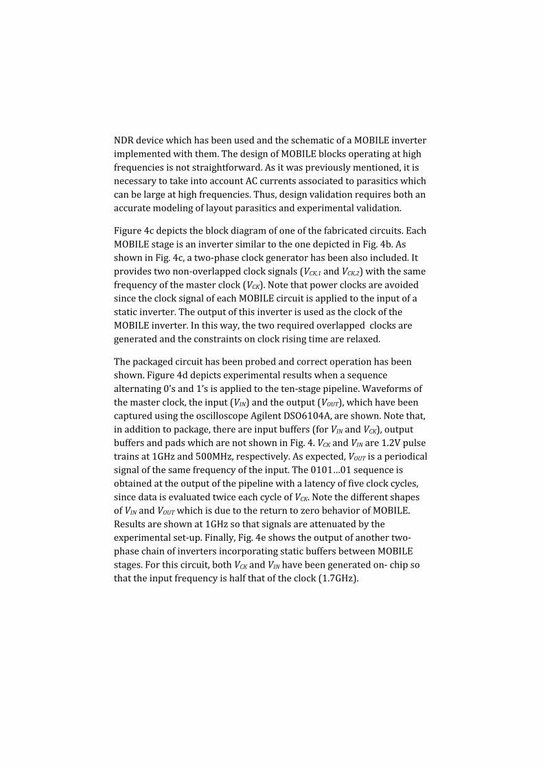
Figure 4c depicts the block diagram of one of the fabricated circuits. Each
MOBILE stage is an inverter similar to the one depicted in Fig. 4b. As
shown in Fig. 4c, a two-phase clock generator has been also included. It
provides two non-overlapped clock signals (VCK,1 and VCK,2) with the same
frequency of the master clock (VCK). Note that power clocks are avoided
since the clock signal of each MOBILE circuit is applied to the input of a
static inverter. The output of this inverter is used as the clock of the
MOBILE inverter. In this way, the two required overlapped clocks are
generated and the constraints on clock rising time are relaxed.
The packaged circuit has been probed and correct operation has been
shown. Figure 4d depicts experimental results when a sequence
alternating 0’s and 1’s is applied to the ten-stage pipeline. Waveforms of
the master clock, the input (VIN) and the output (VOUT), which have been
captured using the oscilloscope Agilent DSO6104A, are shown. Note that,
in addition to package, there are input buffers (for VIN and VCK), output
buffers and pads which are not shown in Fig. 4. VCK and VIN are 1.2V pulse
trains at 1GHz and 500MHz, respectively. As expected, VOUT is a periodical
signal of the same frequency of the input. The 0101…01 sequence is
obtained at the output of the pipeline with a latency of five clock cycles,
since data is evaluated twice each cycle of VCK. Note the different shapes
of VIN and VOUT which is due to the return to zero behavior of MOBILE.
Results are shown at 1GHz so that signals are attenuated by the
experimental set-up. Finally, Fig. 4e shows the output of another two-
phase chain of inverters incorporating static buffers between MOBILE
stages. For this circuit, both VCK and VIN have been generated on- chip so
that the input frequency is half that of the clock (1.7GHz).

(a) (b)
(c)
(d)
(e)
Fig 4. (a) MOS-NDR device. (b) MOBILE inverter implemented with MOS-NDR devices. (c) Block
diagram of a fabricated two-phase chain of inverters. (d) Measured waveforms. (e) Output of a
fabricated two-phase chain of inverter with static buffers as interconnection stages.

4 4-BIT CLA
The two-phase clock scheme has been applied in the design of a 4-bit
RTD-CMOS MOBILE Carry Lookahead Adder (CLA) as a case study. Figure
5a shows the block diagram of a 4-bit CLA. The PGs blocks propagate (Pi =
(a)
(b)
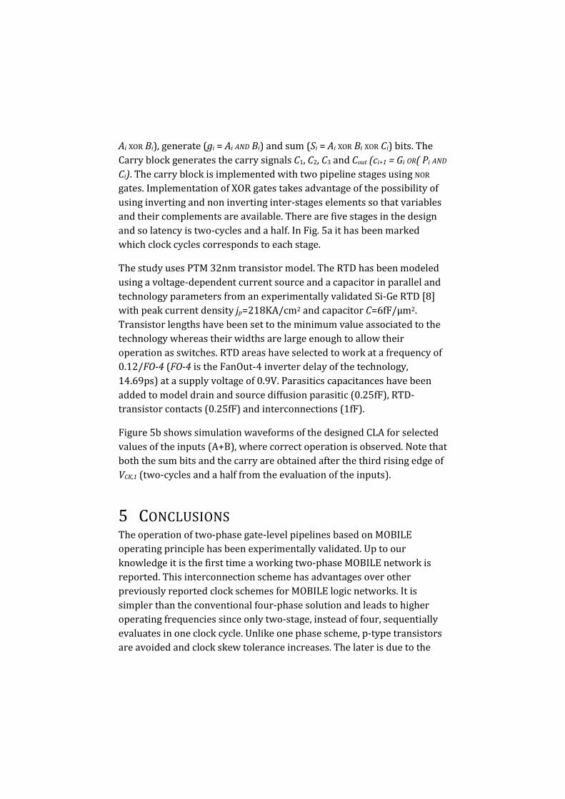
Ai XOR Bi), generate (gi = Ai AND Bi) and sum (Si = Ai XOR Bi XOR Ci) bits. The
Carry block generates the carry signals C1, C2, C3 and Cout (ci+1 = Gi OR( Pi AND
Ci). The carry block is implemented with two pipeline stages using NOR
gates. Implementation of XOR gates takes advantage of the possibility of
using inverting and non inverting inter-stages elements so that variables
and their complements are available. There are five stages in the design
and so latency is two-cycles and a half. In Fig. 5a it has been marked
which clock cycles corresponds to each stage.
The study uses PTM 32nm transistor model. The RTD has been modeled
using a voltage-dependent current source and a capacitor in parallel and
technology parameters from an experimentally validated Si-Ge RTD [8]
with peak current density jp=218KA/cm2 and capacitor C=6fF/μm2.
Transistor lengths have been set to the minimum value associated to the
technology whereas their widths are large enough to allow their
operation as switches. RTD areas have selected to work at a frequency of
0.12/FO-4 (FO-4 is the FanOut-4 inverter delay of the technology,
14.69ps) at a supply voltage of 0.9V. Parasitics capacitances have been
added to model drain and source diffusion parasitic (0.25fF), RTD-
transistor contacts (0.25fF) and interconnections (1fF).
Figure 5b shows simulation waveforms of the designed CLA for selected
values of the inputs (A+B), where correct operation is observed. Note that
both the sum bits and the carry are obtained after the third rising edge of
VCK,1 (two-cycles and a half from the evaluation of the inputs).
5 CONCLUSIONS
The operation of two-phase gate-level pipelines based on MOBILE
operating principle has been experimentally validated. Up to our
knowledge it is the first time a working two-phase MOBILE network is
reported. This interconnection scheme has advantages over other
previously reported clock schemes for MOBILE logic networks. It is
simpler than the conventional four-phase solution and leads to higher
operating frequencies since only two-stage, instead of four, sequentially
evaluates in one clock cycle. Unlike one phase scheme, p-type transistors
are avoided and clock skew tolerance increases. The later is due to the

self-latching property of MOBILE gates which makes possible an opera-
operation taking advantage of the overlapping of the two clock phases to
tolerate clock skew and, in addition, avoids limitations of conventional
CMOS counterparts. The design of a two-phase 4-bit RTD-CMOS CLA has
been carried out as an application example.
Acknowledgement. This work has been funded by Ministerio de
Economía y Competitividad del Gobierno de España with support from
ERDF under Project TEC2010-18937.
REFERENCES
[1] P. Mazumder, S. Kulkarni, M. Bhattacharya, J.P. Sun, and G.I. Haddad, “Digital circuit applications
of resonant tunneling devices”, Proc. IEEE, 86, pp. 664-686, Apr. 1998.
[2] S. Choi , Y. Jeong, J. Lee, and K. Yang, “A Novel High-Speed Multiplexing IC Based on Resonant
Tunneling Diodes”, IEEE Trans. On Nanotechnology, vol. 8, no. 4, pp. 482-486, Jul. 2009.
[3] K. Karda, J. Brockman, S. Sutar, A. Seabaugh, and J. Nahas, “Bistable-Body Tunnel SRAM”, IEEE
Trans. Nanotechnology, vol. PP, no. 9, pp. 1, 2010.
[4] E. Goto, K. Murata, K. Nakazawa, K. Nakagawa, T. Moto-Oka, Y.Ishibashi, T. Soma, and E. Wada,
“Esaki diode high-speed logical circuits,” IRE Trans. Elect. Comp., vol. EC-9, pp. 25–29, 1960.
[5] T. AKeyoshi, T., et al., “Weighted sum threshold logic operation of MOBILE’s (Monostable Bistable
Logic Element) using resonant-tunnelling transistors”, IEEE Electron Device Lett., 14, pp. 475-477,
Oct. 1993.
[6] S. Mohan, et al., "Ultrafast pipelined arithmetic using quantum electronic devices", Computers and
Digital Techniques, IEE Proceedings, 141, (2), pp.104-110, Mar 1994.
[7] H. Matsuzaki, H. Fukuyama and T. Enoki: “Analysis of Transient Response and Operating Speed of
MOBILE”, IEEE Trans. on Electron Devices, Vol. 51, no. 4, pp. 616-622, April 2004.
[8] M.J. Avedillo, J.M. Quintana and H. Pettenghi, “Self-Latching Operation of MOBILE Circuits using
Series-Connection of RTDs and Transistors”, IEEE Trans. on Circuits and Systems-II, Vol. 53, no. 5, pp.
334-338, May 2006.
[9] J. Núñez, M.J. Avedillo and J.M. Quintana, “Simplified single-phase clock scheme for MOBILE
networks”, Electronics Letters, Vol. 47, no. 11, pp. 648-650, May 2011.
[10] J. Núñez, M.J. Avedillo and J.M. Quintana, “Domino Inspired MOBILE Networks”, Electronics
Letters, Vol. 48, no. 5, Feb, 2012.
[11] J. Núñez, M.J. Avedillo and J.M. Quintana, “Efficient Realisation of MOS-NDR Threshold Logic
Gates”, IET Electronics Letters, Vol. 45, no 23, pp. 1158-1160, 2009.

[12] S.Y. Chung, et al, ”Si/SiGe resonant interband tunnel diode with fr0 20.2GHz and peak
current density 218 kA/cm2 for K-band mixed-signal applications”. IEEE Electro Device Lett., vol 27,
pp. 364-367, 2006.