Embed Size (px)
Citation preview

www.DataSheet4U.com
Twido and Altivar Magelis XBT-GT1100 and Preventa
with Osiswitch System User Guide
[source code]
3300
3846
.00
Mar 2006

Twido and Altivar Magelis XBT-GT1100 and Preventa with Osiswitch_EN.doc
Schneider Electric
1
Contents Application Source Code .......................................................................................................3 Typical applications................................................................................................................4 System .....................................................................................................................................5
Architecture.............................................................................................................................5 Installation...............................................................................................................................7
Hardware.............................................................................................................................................................9 Software ............................................................................................................................................................12 Communication .................................................................................................................................................13
Implementation .....................................................................................................................14 HMI ....................................................................................................................................................................15 PLC....................................................................................................................................................................32 Data exchange ..................................................................................................................................................34 Devices..............................................................................................................................................................35
Appendix ...............................................................................................................................38 Detailed components list.......................................................................................................38 Component protection classes..............................................................................................39
Characteristics of the system..............................................................................................40 Component Features ............................................................................................................41
Contact ..................................................................................................................................43
Introduction This document is intended to provide a quick introduction to the described System.
It is not intended to replace any specific product documentation. On the contrary, it offers additional information to the product documentation, for installing, configuring and starting up the system. A detailed functional description or the specification for a specific user application is not part of this document. Nevertheless, the document outlines some typical applications where the system might be implemented.

Twido and Altivar Magelis XBT-GT1100 and Preventa with Osiswitch_EN.doc
Schneider Electric
2
Abbreviations
Word / Expression Signification AC Alternating Current Advantys SE product name for a family of I/O modules Altivar (ATV) SE product name for a family of VSDs CANopen Name for a communications maschine bus system CB Circuit Breaker CoDeSys Hardware-independant IEC 61131-3 programming software ConneXium SE product name for a Family of Transparent Factory devices DC Direct Current EDS Electronic Data Sheet E-STOP Emergency Off switch Harmony SE product name for a family of switches and indicators HMI Human Machine Interface I/O Input/Output IclA (ICLA) SE product name for a compact drive Lexium/Lexium05/LXM SE product name for a family of servo-drives Magelis SE product name for a family of HMI-Devices MB - SL SE name for a serial Modbus communications protocol Micro SE product name for a middle range family of PLCs NIM SE product name for a Network Interface Module PC Personal Computer Phaseo SE product name for a family of power supplies PLC Programmable Logic Computer Powersuite An SE software product for configuring ALTIVAR drives Premium SE product name for a middle range family of PLCs Preventa SE product name for a family of safety devices PS1131 (CoDeSys) SE Product name for PLC programming software with CoDeSys PS Power Supply SE Schneider Electric Sycon SE product name of a Field bus programming software Telefast SE product name for a series of distributed I/O devices Tesys U SE product name for a de-centralised I/O System Twido SE product name of a middle range family of PLCs TwidoSoft SE product name for a PLC programming software Unity (Pro) SE product name for a PLC programming software Vijeo Designer An SE software product for programming Magelis HMI devices VSD Variable Speed Drive WxHxD Dimensions : Width, Height and Depth XBT-L1000 An SE software product for programming Magelis HMI devices

Twido and Altivar Magelis XBT-GT1100 and Preventa with Osiswitch_EN.doc
Schneider Electric
3
Application Source Code
Introduction Examples of the source code used to attain the system function as described in this document
can be downloaded from our „Village“ website under this link. The example source code is in the form of configuration, application and import files. Use the appropriate software tool to either open or import the files.
Extension File Type Software Tool Required AIW Configuration File Advantys CNF Configuration File Sycon CO CANopen definitions file Sycon CSV Comma Seperated Values, Spreadsheet Twidosoft CTX Unity DCF Device Configuration File Advantys DIB Device Independent Bitmap Sycon DOC Document file Microsoft Word DOP Project File Magelis XBTL EDS Electronic Data Sheet – Device Definition Industrial standard FEF Export file PL7 GSD EDS file (Geraete Stamm Datei) Profibus ISL Island file, project file Advantys PB Profibus definitions file Sycon PDF Portable Document Format - document Adobe Acrobat PS2 Export file Powersuite export file RTF Rich Text File - document Microsoft Word STU Project file Unity studio STX Project file PL7 TLX Project file Twinline control tool TWD Project file TwidoSoft VDZ Project file Vijeo Designer XEF Export file Unity Pro ZM2 Project File Zeliosoft

Twido and Altivar Magelis XBT-GT1100 and Preventa with Osiswitch_EN.doc
Schneider Electric
4
Typical applications
Introduction Here you will find a list of the typical applications, and their market segments, where
this system or subsystem can be applied: Industry
• Small automated machine or plant components. • Remote automation systems used to supplement large and medium-sized
machines. Buildings/Services
• Goods elevators, e.g., for use in cafeterias or hospitals. • Climate management in greenhouses.
Application Description Image Freight or goods elevators
This application is used in the implementation of goods elevators, which are for example, used in canteens and hospitals.
Greenhouses This application is used to open/close greenhouse windows and shutters to regulate the climate in the greenhouse.

Twido and Altivar Magelis XBT-GT1100 and Preventa with Osiswitch_EN.doc
Schneider Electric
5
System
Introduction The system chapter describes the architecture, the dimensions, the quantities and different
types of components used within this system.
Architecture
General The control section of this application consists of a PLC, which can be controlled via push
buttons or a Magelis panel. The load section is implemented using an Altivar VSD, which also controls changes of direction, and an additional lockable maintenance switch, which is located between the drive and the motor. In this case, an emergency stop switch is used to initiate shut down and ensure the (optional) safety. The emergency stop switch activates a Preventa analyzing unit and, in the event of an emergency, shuts down the redundant conductors before the drive (safety category 3). The system also has two limit switches, which limit the motor’s path of travel. An additional sensor, which can be used to implement approximate position control via the pulse rate, can be included as an option.
Layout

Twido and Altivar Magelis XBT-GT1100 and Preventa with Osiswitch_EN.doc
Schneider Electric
6
Components Hardware:
• Vario VCD master switch (with red and yellow knob) • Vario VBF master switch (as maintenance switch with black knob) • GV2ME motor circuit breaker • Altivar ATV11 variable speed drive • XALK locking-type emergency stop switch with rotary unlocking (tamper-proof) • Phaseo ABL7 power supply unit • TWIDO modular PLC • Magelis XBT GT1100 operator terminal • XB5 selector switches, push buttons and indicator lamps, from the Harmony Style 5 range • XCK OsySwitch roller limit switches • Standard AC motor Software: • Twidosoft 3.2 • PowerSuite 1.5 (option) • Vijeo-Designer 4.3.0
Quantities of components
Only one unit is needed per system component to fulfill the requirements of the specified task (with the exception of roller limit switches, contactors and buttons/indicator lamps). A detailed list of the required components, including quantities and part numbers, can be found in the Appendix to this document.
Degree of Protection
Not all of the components used within this configuration have been designed to withstand the full range of environmental conditions in the field. These components will, therefore, require additional protection and are only suitable for installation in a control cabinet. For information about which components are suitable for direct installation on site, please refer to the list provided in the Appendix (column headed “In the field, on site”, which also indicates the relevant IP protection class).
Supply voltage 230 V AC Total supply output ~ 3.5 kW Motor output ≤ 0.75 kW Motor brake No Connector cross-section 3x 2.5mm² (L, N, PE)
Technical data
Safety category Cat. 3 (optional)
Safety notice In this application example, Category 3 (according to EN 954-1) has been selected
for the purpose of ensuring safety. The issue of whether a safety category (1-4) is to be adopted and, if so, which one, will be determined by the system’s design and the overall extent to which this system represents a hazard to people and machinery. Safety category 3, based on EN 954-1, is the second highest category there is.
Size/ Dimensions
The compact dimensions of the devices used, e.g., the PLC and PS, mean that the components can be installed in a small control cabinet with the following external dimensions: 350 x 350 x 210 mm (WxHxD). Furthermore, the display elements used to indicate a “group error” and “no protection” can be built into the door of the control cabinet along with the system master switch and emergency stop master switch.

Twido and Altivar Magelis XBT-GT1100 and Preventa with Osiswitch_EN.doc
Schneider Electric
7
Installation
Introduction This chapter describes the steps necessary to set up the hardware and configure the
software required to fulfil the described function of the application.
Assembly
Notes This application was configured to control the amount of light and climate control in a
greenhouse. The components and I/O points listed below represent a cross-section of the components and signals that are the essential minimum for control and display purposes and a select number of optional inputs and outputs which can be used in conjunction with most typical applications (safety/maintenance switches). This document does not claim to be comprehensive and does not absolve users of their duty to check the safety requirements of their equipment and to ensure compliance with the relevant national or international rules and regulations in this respect. Safety category 3, which is suggested here as one possible option, is not necessarily required or adequate for every application. A risk analysis normally defines the safety category to be used. A risk analysis, in accordance with the national and/or international standards and regulations in force, must be drawn up and verified for each individual system.

Twido and Altivar Magelis XBT-GT1100 and Preventa with Osiswitch_EN.doc
Schneider Electric
8
Twido PLC inputs Description PLC wiring DC In 0 DC In 1 DC In 2 DC In 3 DC In 4 DC In 5 DC In 6 DC In 7 DC In 8 DC In 9 DC In 10 DC In 11
Not used, reserved for high-speed counters Not used, reserved for high-speed counters Open selector switch Close selector switch Stop button Limit switch open Limit switch closed Motor circuit breaker OK Variable speed drive OK (RC terminal) Maintenance switch OK (option) Safety present (option) Spare
Twido PLC outputs Description Trans. Out Q0
Trans. Out Q1 Relay Out Q2 Relay Out Q3 Relay Out Q4 Relay Out Q5 Relay Out Q6 Relay Out Q7
PLC ON (24 V) Group fault (24 V) Input LI1 ATV11 (clockwise rotation, close) Input LI2 ATV11 (counterclockwise rotation, open) Input LI3 ATV11 (select bit 0, JOG frequency) Spare (24 V) Spare (24 V) Input LI3 ATV11 (select bit 1, JOG frequency)
Twido 24 V supply Description Com (inputs)
-V Com (+) Com 1 Com 2 Com 3
0 V DC reference voltage 0 V DC reference voltage +24 V DC +15 V DC (ATV11 potential) +24 V DC +15 V DC (ATV11 potential)
ATV11 Description VSD control
circuit wiring LI1 LI2 LI3 LI4 RA RC +15 V
Twido relay Out Q2 Twido relay Out Q3 Twido relay Out Q4 Twido relay Out Q7 +24 V DC Twido In 8 Twido Com 1 and Com 3

Twido and Altivar Magelis XBT-GT1100 and Preventa with Osiswitch_EN.doc
Schneider Electric
9
Hardware
General • The components designed for installation in a control cabinet, i.e., Twido PLC, Phaseo
power supply unit, emergency stop switching device, line circuit breaker, contactors and motor circuit breaker, can be snapped onto a 35 mm top-hat rail.
• The Altivar variable speed drive can also be installed in a control cabinet, but requires an adapter bracket.
• Emergency stop, master and maintenance switches are designed for backplane assembly in the field; all switches can also be installed directly in a control cabinet (e.g., on control cabinet door) without their enclosing housings.
• There are two options available for mounting XB5 push buttons and indicator lamps: 1. option: Using a 22 mm hole drilled into the front door of the control cabinet in the
appropriate position. 2. option: Using an XALD housing, which can house up to 5 push buttons or indicator
lamps. This XALD is designed for backplane assembly or direct wall mounting. • 230 V AC wiring between mains switch, emergency stop switch and relay, 24 V supply
(primary), as well as motor circuit breaker, load relay and VSD. • 24 V DC wiring between power supply unit, PLC, push buttons, indicator lamps and
VSD control circuit. • Drive wiring via relay contacts with potential voltage from the drive (neither 24 V DC
nor 230/400 V AC).
Components
Mains switch
VCF-02GE
(red/yellow switch)
Maintenance
switch
VBF-02GE
(black switch)
EMERGENCY STOP switch
XALK178G
Continued on next page

Twido and Altivar Magelis XBT-GT1100 and Preventa with Osiswitch_EN.doc
Schneider Electric
10
Components Contd.
Harmony Style 5
selector and push button
switch with indicator
lamp
XB5
EMERGENCY STOP fault relay
XPS AC3721
Motor circuit
breaker
Circuit breaker GV2-ME16
Phaseo power
supply unit
ABL7CEM24012
Continued on next page

Twido and Altivar Magelis XBT-GT1100 and Preventa with Osiswitch_EN.doc
Schneider Electric
11
Components Contd.
Twido PLC
TWDLMDA
20DRT
Magelis operator
terminal 3,8”
XBT-GT1100
(rear view)
Osiris roller limit switch
XCD2118P16
Altivar ATV11 variable speed
drive
ATV11PU18M2E

Twido and Altivar Magelis XBT-GT1100 and Preventa with Osiswitch_EN.doc
Schneider Electric
12
Software
General Software is primarily used for programming the Twido, including creating the
configuration for communication and assigning inputs and outputs. The Twidosoft programming tool is used for programming. The HMI application on the Magelis operator terminal is configured using Vijeo-Designer software. The Altivar 11 variable speed drive can be parameterized using the front operator panel. However, the PowerSuite software is a more user-friendly option and can be used for configuring the drive, saving data and quickly restoring existing data/configurations for maintenance purposes. Powersuite can be used to optimize the parameters online. To use the software packages, your PC must have the appropriate Microsoft Windows operating system installed:
• Windows 2000 or • Windows XP
The software tools have the following default install paths:
• Twidosoft C:\Program Files\Schneider Electric\TwidoSoft • Vijeo-Designer C:\Program Files\Schneider Electric\Vijeo-Designer • PowerSuite C:\Program Files\Schneider Electric\PowerSuite
Twidosoft 3.2 Vijeo-Designer 4.3.0 Powersuite V1.5

Twido and Altivar Magelis XBT-GT1100 and Preventa with Osiswitch_EN.doc
Schneider Electric
13
Communication
General A Modbus connection is used to exchange data between the Magelis XBT GT1100
terminal and the Twido PLC. The XBTZ9780 communication cable shown below is needed to connect these two devices. The software driver required for Modbus communication is already contained in the software packages for the Magelis panel and the Twido.
Magelis Communication cable
XBTZ9780

Twido and Altivar Magelis XBT-GT1100 and Preventa with Osiswitch_EN.doc
Schneider Electric
14
Implementation
Introduction The implementation chapter describes all the steps necessary to initialise, to configure, to
program and start-up the system to achieve the application functions as listed below.
Function Functional description
1. All the conditions required to clear the group error lamp must be met, i.e., motor circuit breaker and maintenance switch switched on and safety circuit on. The group error message disappears and the Magelis panel is visible on the main screen.
2. The motor can only be controlled in the “open”/”close” direction if the associated limit switch has not been pressed and no errors are pending.
3. Push buttons: The selection for opening and closing can be activated via the selector switch. Invoking the motion function starts motion in the selected direction. Motion can be stopped by pressing the stop button, selecting the opposite direction or reaching the limit switch. It will also stop if an error occurs. Although operation is always possible via the push button housing, when this function is used, motion is always made at the lowest speed (1).
4. Motion can also be activated by entering a “1” in the “open” or “close” parameter, as appropriate. Motion control via the Magelis panel is ignored if the push button housing selector switch is not in the centre position (priority circuit). Entering “0” in the parameter stops the drive, just as if the hardware stop button had been pressed.
5. Speed pre-selection: The speed for the variable speed drive can be pre-defined via the Magelis terminal. A number from 0 to 3 can be entered (0 = lowest speed). The default setting is 0 and will also return to default when an error occurs.
6. Faults: Faults are displayed as group errors via a fault indicator lamp or as individual fault messages on the Magelis panel.
Layout

Twido and Altivar Magelis XBT-GT1100 and Preventa with Osiswitch_EN.doc
Schneider Electric
15
HMI
Introduction This application features a Magelis XBT GT1100 HMI, which is interfaced with the PLC
via the Modbus protocol. To configure the Magelis, Vijeo-Designer software is used. The procedure is explained in the following pages.
Updating Runtime
1 Depending on the firmware that is delivered within the XBT GT, the runtime of the device might be updated to the version 4.3. To do this, start the Runtime Installer which can be invoked by: - Start - Programs - Schneider Electric - Vijeo-Designer - Runtime Installer
2 The destination device must be inserted In the top box. Please select the XBTGT1000 Series entry.
3 The XBT GT1100 does not
provide an Ethernet port, so you must select Serial.
4 Now you need to connect the
PC and the operator panel by using the cable XBTZG925.

Twido and Altivar Magelis XBT-GT1100 and Preventa with Osiswitch_EN.doc
Schneider Electric
16
Updating Runtime Contd.
5 Windows assigns the USB cable to a specific port - in this case it is mapped to COM3. To check what port it has been mapped to, view the settings by clicking - Start - Control panel - System - Hardware [Tab] - Device Manager - Ports (COM & LPT) [Folder]
6 Back to the configuration screen
for the runtime installer you select the COM port assigned to the USB cable. In this example it is COM3. The setting for the baud rate remains at 115200.
7 Check the Recovery option for
downloading the runtime. Now follow the steps below: 1. Turn off the power supply
for the device. 2. Click Send at the bottom of
the dialog 3. Turn on the power supply
for the device. 4. Do not break the connection
between Magelis panel and PC and do not turn off the power supply while the transfer is active
8 When the transfer has been
successfully finished you will have to acknowledge the message with OK. Please note that no application has been transferred to the HMI device yet. A runtime download normally only needs to be done once.

Twido and Altivar Magelis XBT-GT1100 and Preventa with Osiswitch_EN.doc
Schneider Electric
17
Programming/ Configuration
1 Vijeo Designer has the following components:
1 - Navigator 2 - Info-Display 3 - Inspector 4 - Data list 5 - Feedback Zone 6 - Toolbox
2 After starting Vijeo Designer,
select Create New Project and press Next.
3 Input a Project Name e.g. “Example” and select: Project with Single Target Press Next.
Twido and Altivar Magelis XBT-GT1100 and Preventa with Osiswitch_EN.doc
Schneider Electric
18
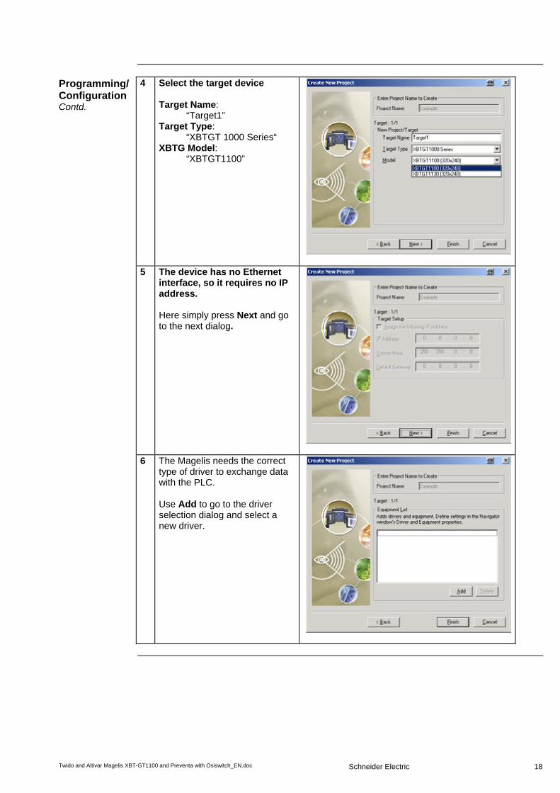
Programming/ Configuration Contd.
4 Select the target device Target Name:
“Target1” Target Type:
“XBTGT 1000 Series“ XBTG Model:
“XBTGT1100”
5 The device has no Ethernet interface, so it requires no IP address. Here simply press Next and go to the next dialog.
6 The Magelis needs the correct type of driver to exchange data with the PLC. Use Add to go to the driver selection dialog and select a new driver.

Twido and Altivar Magelis XBT-GT1100 and Preventa with Osiswitch_EN.doc
Schneider Electric
19
Programming/ Configuration Contd.
7 In the New Driver dialog Select: Manufacturer: “Schneider Electric Industries SAS” Driver: “Modbus(RTU)” Equipment: „Modbus Device” confirm with OK.
8 After setting up the driver you can exit the dialog with Finish.
9 Vijeo-Designer now returns you to its work top, with an empty display and the project navigator A mouseclick on Target1 in the navigator brings up the properties inspector (or if the properties inspector is closed right mouseclick on Target1 and selecting Properties opens up the properties inspector)

Twido and Altivar Magelis XBT-GT1100 and Preventa with Osiswitch_EN.doc
Schneider Electric
20
Programming/ Configuration Contd.
10 Check the properties of the project and in particular the properties of the COM-port. It must be set to serial for the connection to work properly. Ensure that the COM port settings are correct. In this example the USB cable has been assigned to port COM 3. In doubt please check the hardware settings of your systems according step 5 of the runtime installer description.
11 Although downloading to the Magelis will not actually be performed now, you must connect the COM port of the PC with the Tool port on the Magelis to perform the download. Use the USB cable XBTZG925 to make the connection.
Communication Setup
12 In the Navigator, with a right mouseclick on the name, you can Rename the configuration to „TWIDO“.

Twido and Altivar Magelis XBT-GT1100 and Preventa with Osiswitch_EN.doc
Schneider Electric
21
Programming/ Configuration Contd.
13 To edit the configuration, right mouseclick on TWIDO in the navigator and select: configuration.
14 In the Driver Configuration dialog, input: - RS-485 - 19200 Baud - 8 Data bits - 1 Stop bit - No Parity - 2 Retry Counts Exit the dialog with OK. The configuration must match the port definition on the Twido.
15 For the communications to work you must set up the parameters in the Modbus RTU-Driver For this, right mouseclick on ModbusRTU01 in the Navigatorand select Configuration...
16 In this screen retain all the default settings. Click and set the checkbox for IEC61131 Syntax. Following the IEC 61131 syntax addressing with Twido is easier.

Twido and Altivar Magelis XBT-GT1100 and Preventa with Osiswitch_EN.doc
Schneider Electric
22
Programming/ Configuration Contd.
17 After setting the checkbox you have to confirm the action with Yes.
18 To create variables, first click on the Tab variable in the navigator. A right mouse click on Target1 in the navigator opens up the pop-up menu to go to New Variable -> New… and the variable definition dialog.
Configure new variables
19 To create a variable you must input a: • Variable name • Data type • Data Source (External) • Device (Scan Group) • Address in the PLC Here you can address • bits (%M.. & %MW...:X..) • memory words (%MW..) in the PLC. PLC internal formats such as counters muss first be transferred to memory words before the Magelis can display them.
20 Integers and Reals :
%MW** (e.g. MW 2) Discretes:
%M** (e.g. %M2) %MW**:X** (e.g. %MW2:X5)
where „X**“ represents the bit number or word number i.e. address them with the appropriate offset.

Twido and Altivar Magelis XBT-GT1100 and Preventa with Osiswitch_EN.doc
Schneider Electric
23
Programming/ Configuration Contd.
21 In the example code - with the exception of Remote_speed - only Discretes are used for the communication.
Configuration Function keys (R1..R6)
1 For configuring/programming the R1..R6 function keys on the right hand side of the panel there are three possibilities: - general function keys
(action does not depend on the actual screen)
- screen orientated function keys (action depends on the actual screen)
- mixed function keys (general and screen oriented keys within one action)
In this example only general function keys are used. To define general function keys the select FunctionKeys in the property inspector and click on [...].

Twido and Altivar Magelis XBT-GT1100 and Preventa with Osiswitch_EN.doc
Schneider Electric
24
Configuration Function keys (R1..R6) Contd.
2 At the top of the screen you can select the function key you would like to configure, for instance R1. Click on the Add button to create a new action that will be invoked when you press this function key.
3 In the following screen you can
decide in which way the variable should be influenced. In this example the action is a toggle. To select the affected variable, click on the lightbulb icon on the right hand side of the edit box.
4 A list of the available variables is
now opened. Select one with a double click or by marking it and clicking OK. On clicking OK, you return immediately to the previous screen. To confirm the action you have to click again on OK.

Twido and Altivar Magelis XBT-GT1100 and Preventa with Osiswitch_EN.doc
Schneider Electric
25
Configuration Function keys (R1..R6) Contd.
5 Already configured function keys are indicated with an asterisk, for example R3*
Example Insert text
1 Example: Insert Text Select the text icon in the tool bar. The toolbar displays the toolbox with tools for editing the display.
2 Example: Create Text With the text tool you can position the text box on the display. You can adjust its size by „pulling“ on the box or by inserting the width and height in the text editor dialog. To got to the text editor dialog, double click on the text box. In the text editor dialog, you can input the actual text to be displayed and define its size, font, etc.

Twido and Altivar Magelis XBT-GT1100 and Preventa with Osiswitch_EN.doc
Schneider Electric
26
Example Insert text Contd.
3 After inputting the text you can define/change the text characteristics in the Property Inspector
Example Insert lamp
4 Example: Insert Lamp Select the lamp tool in the tool bar. With this tool, position the lamp on the display. You can adjust its size by „pulling“ the sides.

Twido and Altivar Magelis XBT-GT1100 and Preventa with Osiswitch_EN.doc
Schneider Electric
27
Example Insert lamp continued
5 A right mouse click on the lamp object in the display invokes the Lamp Settings dialog. To assign a variable to the lamp click on the light bulb.
6 A list of existing variables will be displayed. Select the variable you need to animate your lamp by double clicking on the specific variable or by marking it and finally confirming the action with OK.
Example Numerical Display
7 Example: Insert numerical display Select the numerical display tool in the tool bar. With this tool, position the field on the display. You can adjust the size of the field by „pulling“ on the sides/corners.

Twido and Altivar Magelis XBT-GT1100 and Preventa with Osiswitch_EN.doc
Schneider Electric
28
Example Numerical display Contd.
8 Ifor the numerical displays you can define: • style of the display • data type (integer/float9 • zero suppress • number of display digits • display/not display zero • Format e.g. hex., dec. • font style • font size • text alignment For the variable used to animate the object shown, you can either manually input the variable name or click on the lightbulb icon to browse the variable list and select one. If you input an unknown variable it is shown in red – the variable has yet to be defined. Once activated variables can be selected and their display format defined. If the value requires further processing before use, such as trigonomic functions, you can select these via the calculator icon.

Twido and Altivar Magelis XBT-GT1100 and Preventa with Osiswitch_EN.doc
Schneider Electric
29
Import and transfer an existing program
1 In order to transfer the program from the PC to the terminal, the two must be connected to each other using the XBTZG925 communication cable.
2 To be able to import a project you have to close the active project first. In the File menu, select Import/Export ->Import Project... The Import Project dialog opens.
3 Vijeo-Designer import/export files are normally stored in the folder backup. Select the file named “Example.vdz” and import it into Vijeo-Designer by double-clicking on it or clicking Open.
4 After finishing the import successfully, you will receive a message that you must acknowledge with OK.

Twido and Altivar Magelis XBT-GT1100 and Preventa with Osiswitch_EN.doc
Schneider Electric
30
Import and transfer an existing program Contd.
5 To communicate with the Twido please connect the XBT GT’s RJ45 jack with the Mini-Din connector on port 1 of the Twido using the cable XBTZ9780.
6 Before you download the application to the HMI device please check for the correct COM port settings in the Property Inspector. If in doubt, please check the hardware settings of your systems according to step 5 of the runtime installer description.

Twido and Altivar Magelis XBT-GT1100 and Preventa with Osiswitch_EN.doc
Schneider Electric
31
Import and transfer an existing program Contd.
7 To check or validate the application, select: Build->Download All Once validated, you can transfer it to the target device.
8 During the download a progress bar will be displayed.
9 Once the download is finished, the Magelis XBT GT1100 automatically establishes a connection with the Twido. By using the R1, R2 and R3 keys on the front of the display you can control the application. By touching the field Speed you can change the speed of the motor(s)

Twido and Altivar Magelis XBT-GT1100 and Preventa with Osiswitch_EN.doc
Schneider Electric
32
PLC
Introduction The PLC chapter describes how to initialize, parameterize and load the program to the
PLC in order to implement the functional description described above. The PLC program is created with Twidosoft.
Pre-conditions
The following conditions must be met in order to carry out the steps described below: • The Twidosoft programming tool is installed on your PC • The “Example.twd“ Twidosoft project is available in the default directory that has
been set up (C:\Program Files\Schneider Electric\TwidoSoft\Applications) • The Twido PLC is switched on and supplied with power • The PLC and the PC are linked to one another via the PC <> Twido programming
cable (TSXPCX3031).
Setting up communi- cation
1 Once the Twido programming software has been launched, start by calling up the "Example.twd" PLC program. To do this, select: File->Open The application default directory in which the file should be located is displayed.
2 Once the program has been loaded, communication with the PLC must be set up. Select: PLC->Select a connection to invoke the dialog for the port definition; in this case, USB.

Twido and Altivar Magelis XBT-GT1100 and Preventa with Osiswitch_EN.doc
Schneider Electric
33
Transferring and running a program
1 To transfer the program, the PLC and the PC must remain connected to each other via the communication cable. Connect the devices and select PLC->Connect to create an online link to the PLC so that you can download the program.
2 Before a program is downloaded to the PLC for the first time, Twidosoft informs you that the program and the PLC content are different. In this case, click on PC-> Controller to transfer the program to the PLC.
3 If an application is already running on the controller, Twidosoft asks if it may stop the PLC and overwrite the existing application. Press OK to stop the controller and download the application.
4 Now click on OK to overwrite the existing application in the controller.
5 When the transfer is completely
finished the controller needs to be started. Select PLC->Run or click on the run icon in the toolbar.
6 To confirm the run action on the controller click the OK button.

Twido and Altivar Magelis XBT-GT1100 and Preventa with Osiswitch_EN.doc
Schneider Electric
34
Data exchange
Introduction In this chapter, the individual points between which data is transferred via a bus
system, (e.g., Modbus, Modbus Plus or TCP/IP) and that are not linked to digital or analog hardware interfaces, are listed. This list defines:
• The devices concerned in each case • The direction of transfer • The symbolic name and • The direct bus address on the device concerned.
Read and write data direction Device 1 Device 2 XBT GT1100 (Modbus master) Twido (Modbus slave) Address Designation Address Designation %MW0:X0 Open %MW0:X0 RMT_CMD_OPEN %MW0:X1 Close %MW0:X1 RMT_CMD_CLOSE %MW0:X2 Stop %MW0:X2 RMT_CMD_STOP %MW1 Speed %MW1 RMT_SPEED
Data direction (device 1 reads from device 2) Device 1 Device 2 XBT GT1100 (Modbus master) Twido (Modbus slave) Address Designation Address Designation %M80 Safety not OK %M80 ERR_STAT_MESS01 %M81 Motor protection off %M81 ERR_STAT_MESS02 %M82 Variable speed drive
error %M82 ERR_STAT_MESS03
%M83 Maintenance switch off %M83 ERR_STAT_MESS04 %M84 Limit switch error %M84 ERR_STAT_MESS05 %M85 Spare error %M85 ERR_STAT_MESS06

Twido and Altivar Magelis XBT-GT1100 and Preventa with Osiswitch_EN.doc
Schneider Electric
35
Devices
Introduction This chapter describes the steps required to initialise and configure the devices to attain
the described system function. PowerSuite software is used to initialize and parameterize the devices.
General The ATV11 parameters can be entered via the front panel on the device itself. However,
using PowerSuite allows you to: • save the data on your PC • print out the documentation and • optimize the parameters online.
Configuration 1 The window opposite appears once the
program has started up. Once you have read the warning message, advance to the next screen using the shortcut Alt+F.
2 The next dialog allows you to define
general user rights. You do not have to make any changes in this dialog. Proceed to the selection of the type of VSD by clicking OK.
3 Select the device type in this window. In this example, we select ATV 11.
Continued on next page

Twido and Altivar Magelis XBT-GT1100 and Preventa with Osiswitch_EN.doc
Schneider Electric
36
Configuration Contd.
4 The models available in the ATV11 series are displayed in the drop-down list on the left of the dialog (circled in red). Select the appropriate variable speed drive by clicking on its part number. The values assigned to the device are displayed on the right-hand side; only the frequency should be set here in accordance with the actual conditions. Next, select Apply and OK in order to transfer the configuration.
5 Here you could make further settings; however, in this example we use the default values.
6 Once this procedure has been completed, you can store the parameters on the PC. Use the diskette icon in the toolbar (or the corresponding menu item).

Twido and Altivar Magelis XBT-GT1100 and Preventa with Osiswitch_EN.doc
Schneider Electric
37
Transferring parameters
1 Check the connection between the PC and the Altivar.
2 You can now transfer the parameters
to the ATV by selecting: Link->Transfer File and then PC to device.

Twido and Altivar Magelis XBT-GT1100 and Preventa with Osiswitch_EN.doc
Schneider Electric
38
Appendix
Detailed components list
Item No. Description Part no. Rev./ Vers.
Hardware components
1.1 1 Master switch VCF02GE 1.2 1 Emergency stop switch housing XALK178G 1.3 1 Preventa emergency stop relay, cat. 3 XPSAC3721 1.4 2 Contactor, 9 A, 24 V DC operated, 3-pole,
AC3, 1x NO + 1x NC LC1D09BD
1.5 1 2-button push button housing, empty XALD02 1.6 1 Selector switch, 3 positions, locking-type XB5AD33 1.7 1 Label holder 30x40 “forward-0-back” ZBY2384 1.8 1 Illuminated button red, flat ZB5AW343 1.9 1 Auxiliary switch module with red LED + 1
auxiliary switch (1x NO) ZB5AW0B42
1.10 1 Label holder 30x40 “stop” ZBY2304 1.11 1 3-button push button housing empty XALD03 1.12 1 Illuminated button blue, flat ZB5AW363 1.13 1 Auxiliary switch module with blue LED + 1
auxiliary switch (1x NO) ZB5AW0B61
1.14 1 Label holder 30x40 “emergency stop” ZBY2330 1.15 1 Indicator lamp white, flat XB5AVB1 1.16 1 Label holder 30x40 “on“ ZBY2311 1.17 2 Position switch Universal (final positions) XCKP2118P16 1.18 2 Miniature circuit breaker C60N 1P 2A C 23726 1.19 1 Miniature circuit breaker C60N 1P+N 1A C 24183 1.20 1 Phaseo power supply
24 V DC/1.2 A ABL7CEM24012
1.21 1 Twido PLC modular device with 20 I/Os TWDLMDA20DRT V3.2 1.22 1 XBT GT 3,8” Magelis operator terminal XBTGT1100 1.23 1 Magelis/PLC connection cable XBTZ9780 1.24 1 Motor circuit breaker, 9 to 14 A, adjustable GV2ME16 1.25 1 Maintenance switch VBF02GE 1.26 1 Auxiliary contact block for maintenance
switch VZ7
1.27 1 Altivar ATV11 variable speed drive ATV11PU18M2E 1.28 1 Altivar adapter for 35mm mounting rail VW3A11851 option

Twido and Altivar Magelis XBT-GT1100 and Preventa with Osiswitch_EN.doc
Schneider Electric
39
Software components Item No. Description Part no. Rev./
Vers. 2.1 1 Twidosoft programming software incl. USB
cable TWDSPU1003V10M 3.2
2.1a 1 Twidosoft programming software TWDSPU1002V10M 3.2 2.1b 1 Twido programming USB cable TSXPCX3031 2.2 1 Vijeo-Designer configuration software for
Magelis XBT G/XBT GT incl. USB cable VJDSUDTGSV43M 4.3.0
2.2a 1 Vijeo-Designer configuration software for Magelis XBT G/XBT GT
VJDSUDTGSV43M 4.3.0
2.2b 1 XBT GT programming USB cable XBTZG925 2.3 1 PowerSuite parameterization software VW3A8104 1.5 2.4 1 Altivar set of connection accessories VW3A8106
Component protection classes
Components In the field,
on site IP 55/IP 65
Front IP 65 Control Cabinet
IP 20
Recommended installation locations/ Protection class Master and maintenance switch X Emergency stop switch housing X Contactor, 9 A, 24 V DC operated,
3-pole AC 3, 1x NO + 1x NC X
2-button/3-button push button housing, empty X
Selector switch, 3 positions X Illuminated buttons, all colors, flat X Auxiliary switch module with LED + 1
auxiliary switch (1x NO), all colors X
Label holder 30x40, all texts X Position switch Universal X Miniature circuit breaker, all types
and ratings X
Motor protection switch, all types and ratings X
Phaseo power supply 24 V DC/1.2 A X
Preventa emergency stop relay Twido PLC X Magelis XBT GT1100 X

Twido and Altivar Magelis XBT-GT1100 and Preventa with Osiswitch_EN.doc
Schneider Electric
40
Characteristics of the system
General The data listed below relates to the system and its features as described and specified in this document. The values represented are determined by:
• The number of I/O points • The number of bus nodes (if present) • The number of instructions/operations • Memory usage
Scan time and cycle time
A cycle time of 2 ms was not exceeded with the present configuration including the required application code. The memory usage of the Twido PLC specified and used in this document was 18% for system/configuration data and 2% for the logic component. Trials with additionally integrated extension modules (a digital I/O module with 16 inputs and 8 relay outputs as well as an analog module with 1 output and 2 inputs, which was used as the I/O level for 2 PID controllers) showed that the cycle time could increase to a maximum of 6 ms. When using the aforementioned two additional extension modules, memory usage for system data rose to 22% but, as expected, memory usage of the logic components did not change.

Twido and Altivar Magelis XBT-GT1100 and Preventa with Osiswitch_EN.doc
Schneider Electric
41
Component Features
Twido PLC
The PLC used in this example comprises the power base of a Twido modular PLC and a programming set comprising software and a programming cable (TWDLMDA20DRT + TWDSPU1001V10M):
• 24 V DC • 12 digital inputs • 8 digital relay outputs • Can be extended up to a maximum of 7 modules (analog and
communication modules are also possible) 3 programming languages:
• Ladder Language (LD) • Instruction List (IL) • Sequential Function Chart/Grafcet (SFC)
Predefined functions:
• Drum controller • High-speed counter up to 5 kHz • Very high-speed counter up to 20 kHz • Frequency meter 1 to 20 kHz • Register areas for LIFO/FIFO execution • PWM/PCS output • External PLC start • PID controller
Phaseo power supply unit
ABL7CEM24012 • 100 to 240 V AC/24 V DC
• 1.2 A secondary • Short-circuit-proof

Twido and Altivar Magelis XBT-GT1100 and Preventa with Osiswitch_EN.doc
Schneider Electric
42
Altivar VSD ATV11 HU18M2E
• 0.75 kW, 230 V AC, single-phase • Integrated class B EMC filter • Temperature range: -10 to + 50°C
• Speed range from 1 to 20 (0 to 200 Hz) • Speed control with flow vector check • Protection of drive and motor • Compact design, side-by-side installation also possible on a top-hat rail
Circuit breaker
GV2ME16 • 9 to 14 A
• Thermal and magnetic (170 A) activation • Lockable

Schneider Electric GmbH Steinheimer Strasse 117 D - 63500 Seligenstadt Germany Twido and Altivar Magelis XBT-GT1100 and Preventa with Osiswitch_EN.doc
As standards, specifications and designs change from time to time, please ask for confirmation of the information given in this publication.
43
Contact
Author Phone E-mail
Schneider Electric GmbH Customer & Market System & Architecture Architecture Definition Support
+49 6182 81 2555 [email protected]


![infoPLC net Tutorial Magelis [Modo de compatibilidad] · Software Installation Software Set-up Hardware Set-up Magelis Controls Starting the XBT-L1000 Software Modbus Plus Networks](https://img.dokumen.tips/doc/110x75/5b0759917f8b9abf568e5f66/infoplc-net-tutorial-magelis-modo-de-compatibilidad-installation-software-set-up.jpg)


![infoPLC net Tutorial Magelis [Modo de compatibilidad]€¦ · 8 Hardware Set-up Power Connection and PC to Magelis XBT-Z915 (V2.2) XBT-Z962 4 3 2 4 V + - 1 ˛ 9 66"˙ ˙ 0: ’& ˇ](https://img.dokumen.tips/doc/110x75/5ead2fbd24fbbe3f95796ae0/infoplc-net-tutorial-magelis-modo-de-compatibilidad-8-hardware-set-up-power-connection.jpg)