Embed Size (px)
Citation preview

3501
0372
02
Magelis XBT GT User Manual35010372 02 eng

2 35010372 02 03/2006
Table of Contents
Safety Information . . . . . . . . . . . . . . . . . . . . . . . . . . . . . . . . . . . .7
About the Book . . . . . . . . . . . . . . . . . . . . . . . . . . . . . . . . . . . . . . . 9
Part I XBT GT Panels . . . . . . . . . . . . . . . . . . . . . . . . . . . . . . . . . 11At a Glance . . . . . . . . . . . . . . . . . . . . . . . . . . . . . . . . . . . . . . . . . . . . . . . . . . . . . 11
Chapter 1 Overview . . . . . . . . . . . . . . . . . . . . . . . . . . . . . . . . . . . . . . . . . . . 13At a Glance . . . . . . . . . . . . . . . . . . . . . . . . . . . . . . . . . . . . . . . . . . . . . . . . . . . . . 13XBT GT Series of Panels . . . . . . . . . . . . . . . . . . . . . . . . . . . . . . . . . . . . . . . . . . 14Package Contents . . . . . . . . . . . . . . . . . . . . . . . . . . . . . . . . . . . . . . . . . . . . . . . . 17Series XBT GT Panels and Standards . . . . . . . . . . . . . . . . . . . . . . . . . . . . . . . . 20CE Marking Notes . . . . . . . . . . . . . . . . . . . . . . . . . . . . . . . . . . . . . . . . . . . . . . . . 23
Chapter 2 XBT GT Device Connectivity . . . . . . . . . . . . . . . . . . . . . . . . . . . 25At a Glance . . . . . . . . . . . . . . . . . . . . . . . . . . . . . . . . . . . . . . . . . . . . . . . . . . . . . 25System Design . . . . . . . . . . . . . . . . . . . . . . . . . . . . . . . . . . . . . . . . . . . . . . . . . . 26Accessories . . . . . . . . . . . . . . . . . . . . . . . . . . . . . . . . . . . . . . . . . . . . . . . . . . . . . 29
Chapter 3 Specifications . . . . . . . . . . . . . . . . . . . . . . . . . . . . . . . . . . . . . . .33At a Glance . . . . . . . . . . . . . . . . . . . . . . . . . . . . . . . . . . . . . . . . . . . . . . . . . . . . . 33
3.1 General Specifications . . . . . . . . . . . . . . . . . . . . . . . . . . . . . . . . . . . . . . . . . . . . 35At a Glance . . . . . . . . . . . . . . . . . . . . . . . . . . . . . . . . . . . . . . . . . . . . . . . . . . . . . 35Electrical Specifications. . . . . . . . . . . . . . . . . . . . . . . . . . . . . . . . . . . . . . . . . . . . 36Environmental Specifications . . . . . . . . . . . . . . . . . . . . . . . . . . . . . . . . . . . . . . . 37Structural Specifications . . . . . . . . . . . . . . . . . . . . . . . . . . . . . . . . . . . . . . . . . . . 39
3.2 Functional Specifications. . . . . . . . . . . . . . . . . . . . . . . . . . . . . . . . . . . . . . . . . . . 41At a Glance . . . . . . . . . . . . . . . . . . . . . . . . . . . . . . . . . . . . . . . . . . . . . . . . . . . . . 41Display. . . . . . . . . . . . . . . . . . . . . . . . . . . . . . . . . . . . . . . . . . . . . . . . . . . . . . . . . 42Memory, Clock, and Touch Panel . . . . . . . . . . . . . . . . . . . . . . . . . . . . . . . . . . . . 45Interface . . . . . . . . . . . . . . . . . . . . . . . . . . . . . . . . . . . . . . . . . . . . . . . . . . . . . . . 47
3.3 Interface Specifications . . . . . . . . . . . . . . . . . . . . . . . . . . . . . . . . . . . . . . . . . . . . 49At a Glance . . . . . . . . . . . . . . . . . . . . . . . . . . . . . . . . . . . . . . . . . . . . . . . . . . . . . 49Specifications of Serial Interface COM1 . . . . . . . . . . . . . . . . . . . . . . . . . . . . . . . 50Specifications of Serial Interface COM2 . . . . . . . . . . . . . . . . . . . . . . . . . . . . . . . 54
35010372 02 03/2006 3
Other Interfaces . . . . . . . . . . . . . . . . . . . . . . . . . . . . . . . . . . . . . . . . . . . . . . . . . . 553.4 Part Numbers and Functions . . . . . . . . . . . . . . . . . . . . . . . . . . . . . . . . . . . . . . . . 57
At a Glance . . . . . . . . . . . . . . . . . . . . . . . . . . . . . . . . . . . . . . . . . . . . . . . . . . . . . 57Parts Identification and Functions . . . . . . . . . . . . . . . . . . . . . . . . . . . . . . . . . . . . 58Terminal Configuration Switches . . . . . . . . . . . . . . . . . . . . . . . . . . . . . . . . . . . . . 80
3.5 Dimensions . . . . . . . . . . . . . . . . . . . . . . . . . . . . . . . . . . . . . . . . . . . . . . . . . . . . . 84At a Glance . . . . . . . . . . . . . . . . . . . . . . . . . . . . . . . . . . . . . . . . . . . . . . . . . . . . . 84XBT GT1000 Series Dimensions . . . . . . . . . . . . . . . . . . . . . . . . . . . . . . . . . . . . 85XBT GT2000 Series Dimensions . . . . . . . . . . . . . . . . . . . . . . . . . . . . . . . . . . . . . 88XBT GT4000 Series Dimensions . . . . . . . . . . . . . . . . . . . . . . . . . . . . . . . . . . . . . 92XBT GT5000 Series Dimensions . . . . . . . . . . . . . . . . . . . . . . . . . . . . . . . . . . . . . 96XBT GT6000 Series Dimensions . . . . . . . . . . . . . . . . . . . . . . . . . . . . . . . . . . . . 104XBT GT7000 Series Dimensions . . . . . . . . . . . . . . . . . . . . . . . . . . . . . . . . . . . . 108Panel Cut Dimension . . . . . . . . . . . . . . . . . . . . . . . . . . . . . . . . . . . . . . . . . . . . . 112Installation Fasteners. . . . . . . . . . . . . . . . . . . . . . . . . . . . . . . . . . . . . . . . . . . . . 114
Chapter 4 Installation and Wiring . . . . . . . . . . . . . . . . . . . . . . . . . . . . . . 117At a glance . . . . . . . . . . . . . . . . . . . . . . . . . . . . . . . . . . . . . . . . . . . . . . . . . . . . . 117
4.1 Installation . . . . . . . . . . . . . . . . . . . . . . . . . . . . . . . . . . . . . . . . . . . . . . . . . . . . . 119Installation Procedures . . . . . . . . . . . . . . . . . . . . . . . . . . . . . . . . . . . . . . . . . . . 119
4.2 Wiring Precautions. . . . . . . . . . . . . . . . . . . . . . . . . . . . . . . . . . . . . . . . . . . . . . . 126At a glance . . . . . . . . . . . . . . . . . . . . . . . . . . . . . . . . . . . . . . . . . . . . . . . . . . . . . 126Connecting the Power Cord. . . . . . . . . . . . . . . . . . . . . . . . . . . . . . . . . . . . . . . . 127Connecting the Power Supply . . . . . . . . . . . . . . . . . . . . . . . . . . . . . . . . . . . . . . 130Grounding . . . . . . . . . . . . . . . . . . . . . . . . . . . . . . . . . . . . . . . . . . . . . . . . . . . . . 132Input/Output Line placement . . . . . . . . . . . . . . . . . . . . . . . . . . . . . . . . . . . . . . . 134
4.3 Tool Port Connector. . . . . . . . . . . . . . . . . . . . . . . . . . . . . . . . . . . . . . . . . . . . . . 135At a Glance . . . . . . . . . . . . . . . . . . . . . . . . . . . . . . . . . . . . . . . . . . . . . . . . . . . . 135Presentation. . . . . . . . . . . . . . . . . . . . . . . . . . . . . . . . . . . . . . . . . . . . . . . . . . . . 136USB Data Transfer Cable (XBT ZG925) - USB Driver Installation . . . . . . . . . . 137
4.4 Ethernet Cable Connector . . . . . . . . . . . . . . . . . . . . . . . . . . . . . . . . . . . . . . . . . 140Presentation. . . . . . . . . . . . . . . . . . . . . . . . . . . . . . . . . . . . . . . . . . . . . . . . . . . . 140
4.5 CF Card . . . . . . . . . . . . . . . . . . . . . . . . . . . . . . . . . . . . . . . . . . . . . . . . . . . . . . . 143CF Card Installation and Removal . . . . . . . . . . . . . . . . . . . . . . . . . . . . . . . . . . . 143
4.6 USB Port . . . . . . . . . . . . . . . . . . . . . . . . . . . . . . . . . . . . . . . . . . . . . . . . . . . . . . 147At a Glance . . . . . . . . . . . . . . . . . . . . . . . . . . . . . . . . . . . . . . . . . . . . . . . . . . . . 147Presentation. . . . . . . . . . . . . . . . . . . . . . . . . . . . . . . . . . . . . . . . . . . . . . . . . . . . 148USB Data Transfer Cable (XBT ZG935) - USB Driver Installation . . . . . . . . . . 149USB Cable Clamp . . . . . . . . . . . . . . . . . . . . . . . . . . . . . . . . . . . . . . . . . . . . . . . 153USB Holder . . . . . . . . . . . . . . . . . . . . . . . . . . . . . . . . . . . . . . . . . . . . . . . . . . . . 155
4.7 AUX Connector . . . . . . . . . . . . . . . . . . . . . . . . . . . . . . . . . . . . . . . . . . . . . . . . . 158AUX Connector . . . . . . . . . . . . . . . . . . . . . . . . . . . . . . . . . . . . . . . . . . . . . . . . . 158
Part II Setting and Debugging . . . . . . . . . . . . . . . . . . . . . . . . . .161At a Glance . . . . . . . . . . . . . . . . . . . . . . . . . . . . . . . . . . . . . . . . . . . . . . . . . . . . 161
4 35010372 02 03/2006
Chapter 5 Settings . . . . . . . . . . . . . . . . . . . . . . . . . . . . . . . . . . . . . . . . . . .163At a Glance . . . . . . . . . . . . . . . . . . . . . . . . . . . . . . . . . . . . . . . . . . . . . . . . . . . . 163
5.1 XBT GT Settings . . . . . . . . . . . . . . . . . . . . . . . . . . . . . . . . . . . . . . . . . . . . . . . . 165At a Glance . . . . . . . . . . . . . . . . . . . . . . . . . . . . . . . . . . . . . . . . . . . . . . . . . . . . 165Types of Settings. . . . . . . . . . . . . . . . . . . . . . . . . . . . . . . . . . . . . . . . . . . . . . . . 166Offline Settings . . . . . . . . . . . . . . . . . . . . . . . . . . . . . . . . . . . . . . . . . . . . . . . . . 167System Settings . . . . . . . . . . . . . . . . . . . . . . . . . . . . . . . . . . . . . . . . . . . . . . . . 170
Chapter 6 Troubleshooting . . . . . . . . . . . . . . . . . . . . . . . . . . . . . . . . . . . .173At a Glance . . . . . . . . . . . . . . . . . . . . . . . . . . . . . . . . . . . . . . . . . . . . . . . . . . . . 173Troubleshooting Checklists . . . . . . . . . . . . . . . . . . . . . . . . . . . . . . . . . . . . . . . . 174Self Test List . . . . . . . . . . . . . . . . . . . . . . . . . . . . . . . . . . . . . . . . . . . . . . . . . . . 178
Chapter 7 Maintenance . . . . . . . . . . . . . . . . . . . . . . . . . . . . . . . . . . . . . . .181At a Glance . . . . . . . . . . . . . . . . . . . . . . . . . . . . . . . . . . . . . . . . . . . . . . . . . . . . 181Regular Cleaning. . . . . . . . . . . . . . . . . . . . . . . . . . . . . . . . . . . . . . . . . . . . . . . . 182Periodic Check Points . . . . . . . . . . . . . . . . . . . . . . . . . . . . . . . . . . . . . . . . . . . . 184Replacing the Backlight. . . . . . . . . . . . . . . . . . . . . . . . . . . . . . . . . . . . . . . . . . . 185
Index . . . . . . . . . . . . . . . . . . . . . . . . . . . . . . . . . . . . . . . . . . . . . 187
35010372 02 03/2006 5

6 35010372 02 03/2006
§
Safety InformationImportant Information
NOTICE Read these instructions carefully, and look at the equipment to become familiar with the device before trying to install, operate, or maintain it. The following special messages may appear throughout this documentation or on the equipment to warn of potential hazards or to call attention to information that clarifies or simplifies a procedure.
The addition of this symbol to a Danger or Warning safety label indicatesthat an electrical hazard exists, which will result in personal injury if theinstructions are not followed.
This is the safety alert symbol. It is used to alert you to potential personalinjury hazards. Obey all safety messages that follow this symbol to avoidpossible injury or death.
DANGER indicates an imminently hazardous situation, which, if not avoided, will result in death, serious injury, or equipment damage.
DANGER
WARNING indicates a potentially hazardous situation, which, if not avoided, can result in death, serious injury, or equipment damage.
WARNING
CAUTION indicates a potentially hazardous situation, which, if not avoided, can result in injury or equipment damage.
CAUTION
35010372 02 03/2006 7
Safety Information
PLEASE NOTE Electrical equipment should be serviced only by qualified personnel. No responsibility is assumed by Schneider Electric for any consequences arising out of the use of this material. This document is not intended as an instruction manual for untrained persons.
© 2005 Schneider Electric. All Rights Reserved.
8 35010372 02 03/2006
About the Book
At a Glance
Document Scope This manual describes how to use the Magelis XBT GT device.
Validity Note Using the Magelis XBT GT device.
User Comments We welcome your comments about this document. You can reach us by e-mail at [email protected]
35010372 02 03/2006 9

About the Book
10 35010372 02 03/2006
35010372 02 03/2006
I
XBT GT PanelsAt a Glance
Overview This part presents XBT GT Panels.
What's in this Part?
This part contains the following chapters:
Chapter Chapter Name Page
1 Overview 13
2 XBT GT Device Connectivity 25
3 Specifications 33
4 Installation and Wiring 117
11

XBT GT Panels
12 35010372 02 03/2006
35010372 02 03/2006
1
OverviewAt a Glance
Overview This chapter presents series of XBT GT Panels and devices connectable to the XBT GT.
What's in this Chapter?
This chapter contains the following topics:
Topic Page
XBT GT Series of Panels 14
Package Contents 17
Series XBT GT Panels and Standards 20
CE Marking Notes 23
13
Overview
XBT GT Series of Panels
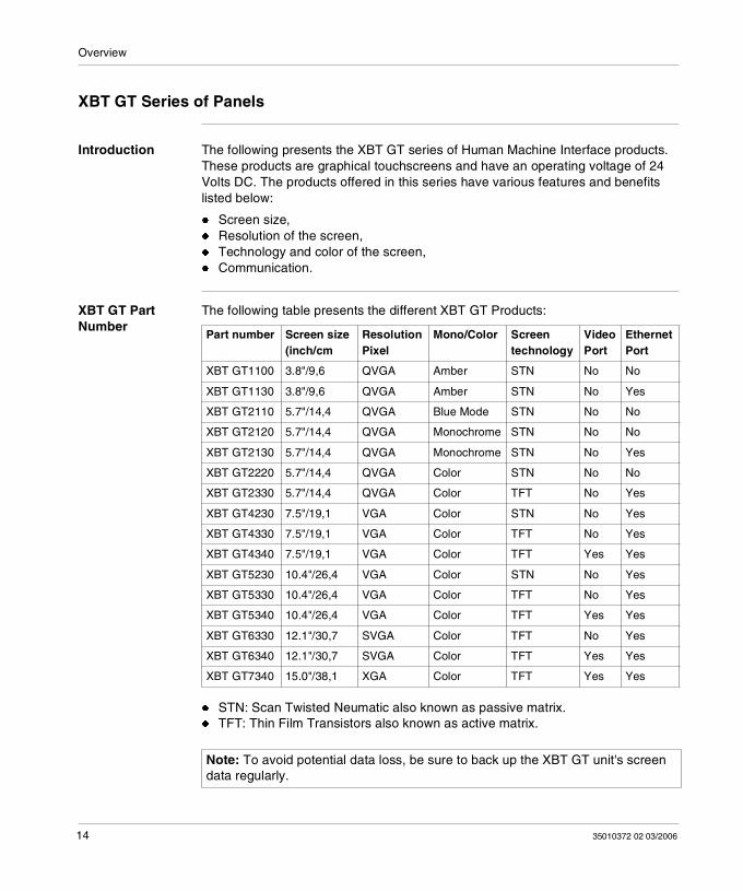
Introduction The following presents the XBT GT series of Human Machine Interface products. These products are graphical touchscreens and have an operating voltage of 24 Volts DC. The products offered in this series have various features and benefits listed below:
Screen size, Resolution of the screen, Technology and color of the screen, Communication.
XBT GT Part Number
The following table presents the different XBT GT Products:
STN: Scan Twisted Neumatic also known as passive matrix. TFT: Thin Film Transistors also known as active matrix.
Part number Screen size (inch/cm
Resolution Pixel
Mono/Color Screen technology
Video Port
Ethernet Port
XBT GT1100 3.8"/9,6 QVGA Amber STN No No
XBT GT1130 3.8"/9,6 QVGA Amber STN No Yes
XBT GT2110 5.7"/14,4 QVGA Blue Mode STN No No
XBT GT2120 5.7"/14,4 QVGA Monochrome STN No No
XBT GT2130 5.7"/14,4 QVGA Monochrome STN No Yes
XBT GT2220 5.7"/14,4 QVGA Color STN No No
XBT GT2330 5.7"/14,4 QVGA Color TFT No Yes
XBT GT4230 7.5"/19,1 VGA Color STN No Yes
XBT GT4330 7.5"/19,1 VGA Color TFT No Yes
XBT GT4340 7.5"/19,1 VGA Color TFT Yes Yes
XBT GT5230 10.4"/26,4 VGA Color STN No Yes
XBT GT5330 10.4"/26,4 VGA Color TFT No Yes
XBT GT5340 10.4"/26,4 VGA Color TFT Yes Yes
XBT GT6330 12.1"/30,7 SVGA Color TFT No Yes
XBT GT6340 12.1"/30,7 SVGA Color TFT Yes Yes
XBT GT7340 15.0"/38,1 XGA Color TFT Yes Yes
Note: To avoid potential data loss, be sure to back up the XBT GT unit's screen data regularly.
14 35010372 02 03/2006
Overview
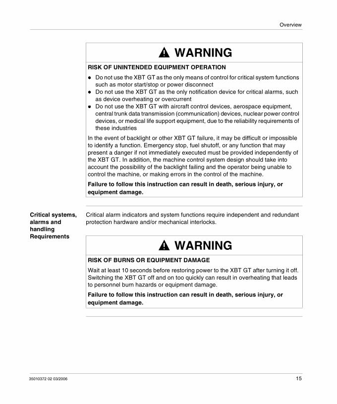
Critical systems, alarms and handling Requirements
Critical alarm indicators and system functions require independent and redundant protection hardware and/or mechanical interlocks.
WARNINGRISK OF UNINTENDED EQUIPMENT OPERATION
Do not use the XBT GT as the only means of control for critical system functions such as motor start/stop or power disconnect
Do not use the XBT GT as the only notification device for critical alarms, such as device overheating or overcurrent
Do not use the XBT GT with aircraft control devices, aerospace equipment, central trunk data transmission (communication) devices, nuclear power control devices, or medical life support equipment, due to the reliability requirements of these industries
In the event of backlight or other XBT GT failure, it may be difficult or impossible to identify a function. Emergency stop, fuel shutoff, or any function that may present a danger if not immediately executed must be provided independently of the XBT GT. In addition, the machine control system design should take into account the possibility of the backlight failing and the operator being unable to control the machine, or making errors in the control of the machine.
Failure to follow this instruction can result in death, serious injury, or equipment damage.
WARNINGRISK OF BURNS OR EQUIPMENT DAMAGE
Wait at least 10 seconds before restoring power to the XBT GT after turning it off. Switching the XBT GT off and on too quickly can result in overheating that leads to personnel burn hazards or equipment damage.
Failure to follow this instruction can result in death, serious injury, or equipment damage.
35010372 02 03/2006 15
Overview
Handling the LCD panel
The following characteristics are specific to XBT GT’s LCD unit and shall not be considered as defects:
LCD screen may show unevenness in the brightness of certain images or may appear different when seen from outside the specified viewing angle. Extended shadows, or "Crosstalk" may also appear on the sides of screen images.
LCD screen pixels may contain black and white colored spots and color display may seem to have changed.
When the same image is displayed on the XBT GT unit’s screen for a long period, an afterimage may appear when the image is changed. If this happens, turn OFF the XBT GT, wait 10 seconds and then restart the unit.
Note: Change the screen image periodically and try not to display the same image for a long period of time.
WARNINGRISK OF SERIOUS EYE AND SKIN INJURY FROM DAMAGED OR LEAKING LCD PANEL
Do not touch nor handle an XBT GT whose LCD panel appears damaged or seems to be leaking.
Do not use sharp objects or tools in the vicinity of the LCD touch panel or to operate its buttons.
Handle the LCD panel carefully to prevent puncture, bursting, or cracking of the panel material.
The LCD panel's liquid contains an irritant. If the panel is damaged and any of this liquid is in contact with your skin, immediately rinse the area with running water for at least 15 minutes. If the liquid gets in your eyes, immediately rinse your eyes with running water for at least 15 minutes and consult a doctor.
Failure to follow this instruction can result in death, serious injury, or equipment damage.
16 35010372 02 03/2006
Overview
Package Contents
Introduction The following items are included in the XBT GT's package. Before using the XBT GT, please make sure that all items listed here are present:
XBT GT Unit, Power Plug, Quick Reference Guide, Screw Installation Fasteners (x4, except for XBT GT 7000 series: x8), Installation Gasket, USB Holder (for XBT GT2000 series only), USB Holder 1 Set (for XBT GT4000, 5000, 6000, and 7000 series), USB Cable Clamp (for XBT GT2000 series only), AUX Connector (for XBT GT4000, 5000, 6000, and 7000 series), RCA-BNC Convertor (for XBT GT5000, 6000, and 7000 series).
This unit has been carefully packed with special attention to quality. However, should you find anything damaged or missing, please contact your local XBT GT distributor immediately.
35010372 02 03/2006 17
Overview
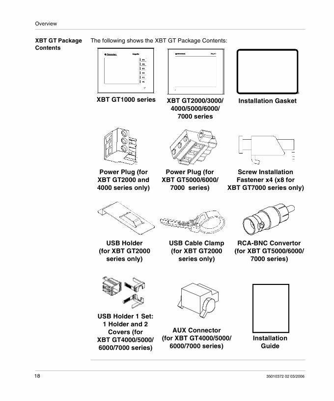
XBT GT Package Contents
The following shows the XBT GT Package Contents:
Installation Gasket
Power Plug (for XBT GT2000 and 4000 series only)
Screw InstallationFastener x4 (x8 for
XBT GT7000 series only)
Installation Guide
XBT GT2000/3000/4000/5000/6000/
7000 series
XBT GT1000 series
AUX Connector (for XBT GT4000/5000/
6000/7000 series)
USB Holder(for XBT GT2000
series only)
USB Cable Clamp(for XBT GT2000
series only)
USB Holder 1 Set: 1 Holder and 2
Covers (for XBT GT4000/5000/6000/7000 series)
RCA-BNC Convertor (for XBT GT5000/6000/
7000 series)
Power Plug (for XBT GT5000/6000/
7000 series)
18 35010372 02 03/2006
Overview
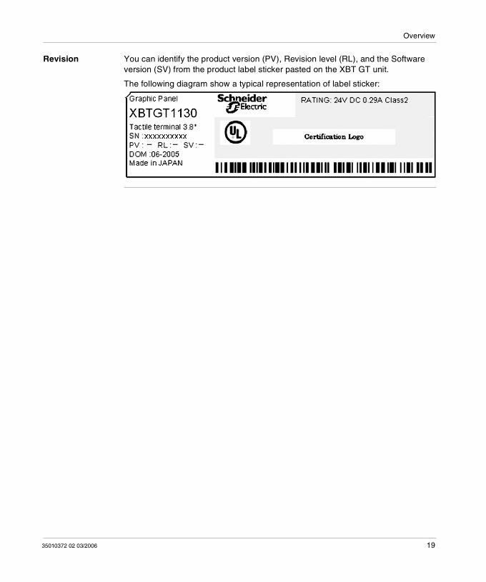
Revision You can identify the product version (PV), Revision level (RL), and the Software version (SV) from the product label sticker pasted on the XBT GT unit.
The following diagram show a typical representation of label sticker:
35010372 02 03/2006 19
Overview
Series XBT GT Panels and Standards
Introduction The XBT GT series of panels are cULus listed and CSA Certified.
These units have been developed to conform with the following standards:
UL 508 for Industrial Control Equipment, UL 1604 Electrical Equipment for Use in Class I and Class II Division 2 and Class
III Hazardous Locations, UL 60950 Standard for Safety of Information Technology Equipment, CAN/CSA-C22.2, No.14, No.213, and No. 60950 Industrial Control Equipment
Miscellaneous Apparatus - For Hazardous Locations.
UL1604 Conditions of Acceptability and Handling Cautions:
20 35010372 02 03/2006
Overview
DANGER
RISK OF EXPLOSION
Compatibility: Power, input and output (I/O) wiring must be in
accordance with Class I, Division 2 wiring methods - Article 501- 4(b) of the National Electrical Code, Groups A, B, C and D Hazardous Locations or Non-Hazardous Locations, NFPA 70 or as specified in section 18-152 of the Canadian Electrical Code for installations within Canada and in accordance with the authority having jurisdiction.
Do not perform substitution of components that may impair compliance to Class I, Division 2.
Confirm that the location is not subject to any risk of explosion before connecting or disconnecting equipment, replacing or wiring modules.
Confirm that the externally connected unit and each interface (COM1, COM2, EXT1, EXT2, CF Card, AUX) and the CF Card Cover and the AUX Connector have been securely locked.
Confirm that the power supply has been turned OFF before disconnecting, replacing or wiring modules.
Before turning ON, sweep front panel with a damp cloth.
Failure to follow this instruction will result in death or serious injury.
DANGERRISK OF EXPLOSION
35010372 02 03/2006 21
Overview
Compatibility: Power, input and output (I/O) wiring must be in accordance with Class I, Division 2 wiring methods - Article 501- 4(b) of the National Electrical Code, Groups A, B, C and D Hazardous Locations or Non-Hazardous Locations, NFPA 70 or as specified in section 18-152 of the Canadian Electrical Code for installations within Canada and in accordance with the authority having jurisdiction.
Do not perform substitution of components that may impair compliance to Class I, Division 2.
Confirm that the location is not subject to any risk of explosion before connecting or disconnecting equipment, replacing or wiring modules.
Confirm that the externally connected unit and each interface (COM1, COM2, EXT1, EXT2, CF Card, AUX) and the CF Card Cover and the AUX Connector have been securely locked.
Confirm that the power supply has been turned OFF before disconnecting, replacing or wiring modules.
Before turning ON, sweep front panel with a damp cloth.
Failure to follow this instruction will result in death, serious injury, or equipment damage.
DANGER
22 35010372 02 03/2006
Overview
CE Marking Notes
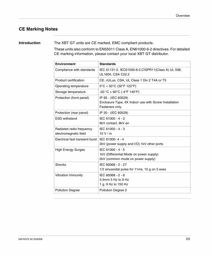
Introduction The XBT GT units are CE marked, EMC compliant products.
These units also conform to EN55011 Class A, EN61000-6-2 directives. For detailed CE marking information, please contact your local XBT GT distributor.
Environment Standards
Compliance with standards IEC 61131-2, IEC61000-6-2,CISPR11(Class A) UL 508, UL1604, CSA C22.2
Product certification CE, cULus, CSA, UL Class 1 Div 2 T4A or T5
Operating temperature 0°C + 50°C (32°F 122°F)
Storage temperature -20 °C + 60°C (-4°F 140°F)
Protection (front panel) IP 65 - (IEC 60529)Enclosure Type, 4X Indoor use with Screw Installation Fasteners only.
Protection (rear panel) IP 20 - (IEC 60529)
ESD withstand IEC 61000 - 4 - 26kV contact, 8kV air
Radiated radio frequency electromagnetic field
IEC 61000 - 4 - 310 V / m
Electrical fast transient burst IEC 61000- 4 - 42kV (power supply and I/O) 1kV other ports
High Energy Surges IEC 61000 - 4 - 51kV (Differential Mode on power supply)2kV (common mode on power supply)
Shocks IEC 60068 - 2 - 271/2 sinusoidal pulse for 11ms, 15 g on 3 axes
Vibration Immunity IEC 60068 - 2 - 63.5mm 5 Hz to 9 Hz1 g. 9 Hz to 150 Hz
Pollution Degree Pollution Degree 2
35010372 02 03/2006 23

Overview
24 35010372 02 03/2006
35010372 02 03/2006
2
XBT GT Device ConnectivityAt a Glance
Introduction This chapter presents for each XBT GT unit the equipment connectable to it.
What's in this Chapter?
This chapter contains the following topics:
Topic Page
System Design 26
Accessories 29
25
XBT GT Device Connectivity
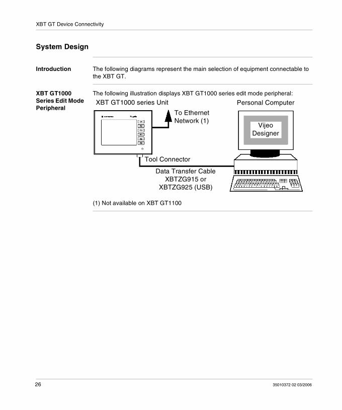
System Design
Introduction The following diagrams represent the main selection of equipment connectable to the XBT GT.
XBT GT1000 Series Edit Mode Peripheral
The following illustration displays XBT GT1000 series edit mode peripheral:
(1) Not available on XBT GT1100
XBT GT1000 series Unit Personal Computer
VijeoDesigner
To EthernetNetwork (1)
Data Transfer CableXBTZG915 or
XBTZG925 (USB)
Tool Connector
26 35010372 02 03/2006
XBT GT Device Connectivity
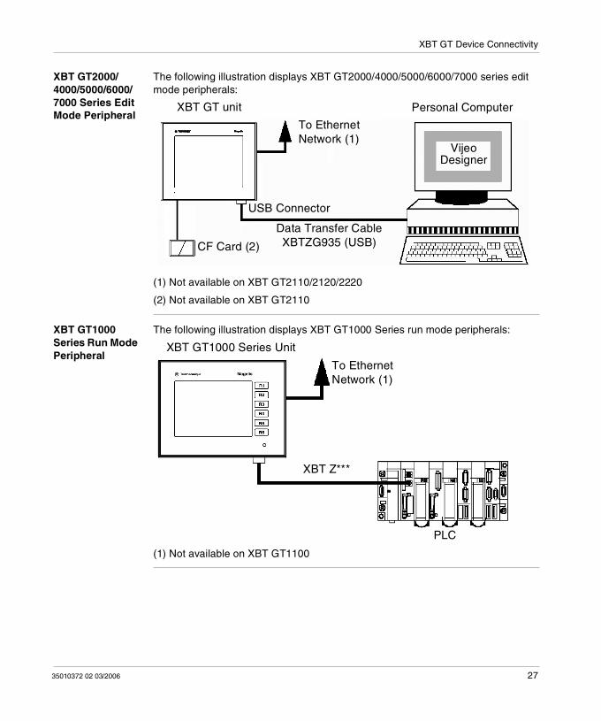
XBT GT2000/4000/5000/6000/7000 Series Edit Mode Peripheral
The following illustration displays XBT GT2000/4000/5000/6000/7000 series edit mode peripherals:
(1) Not available on XBT GT2110/2120/2220
(2) Not available on XBT GT2110
XBT GT1000 Series Run Mode Peripheral
The following illustration displays XBT GT1000 Series run mode peripherals:
(1) Not available on XBT GT1100
To EthernetNetwork (1)
XBT GT unit
VijeoDesigner
USB Connector
Personal Computer
CF Card (2)
Data Transfer CableXBTZG935 (USB)
To EthernetNetwork (1)
XBT GT1000 Series Unit
PLC
XBT Z***
35010372 02 03/2006 27
XBT GT Device Connectivity
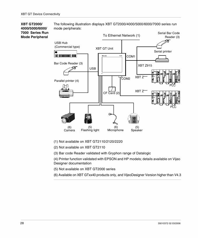
XBT GT2000/4000/5000/6000/7000 Series Run Mode Peripheral
The following illustration displays XBT GT2000/4000/5000/6000/7000 series run mode peripherals:
(1) Not available on XBT GT2110/2120/2220
(2) Not available on XBT GT2110
(3) Bar code Reader validated with Gryphon range of Datalogic
(4) Printer function validated with EPSON and HP models; details available on Vijeo Designer documentation
(5) Not available on XBT GT2000 series
(6) Available on XBT GTxx40 products only, and VijeoDesigner Version higher than V4.3
XBT GT Unit
XBT Z***
PLC
CF Card (2)
Parallel printer (4)
To Ethernet Network (1)
Bar Code Reader (3)
USB Hub(Commercial type)
USB
COM1
COM2
Serial printer
Serial Bar CodeReader (3)
PLC
XBT Z***
XBT Z915
(6)Camera
(5)Flashing light
(6)Microphone
(5)Speaker
28 35010372 02 03/2006
XBT GT Device Connectivity
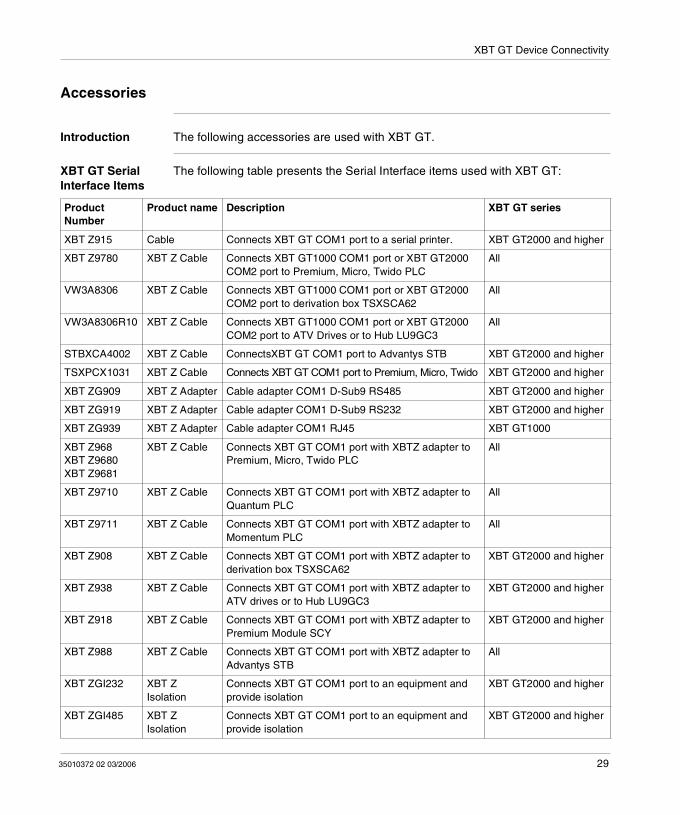
Accessories
Introduction The following accessories are used with XBT GT.
XBT GT Serial Interface Items
The following table presents the Serial Interface items used with XBT GT:
Product Number
Product name Description XBT GT series
XBT Z915 Cable Connects XBT GT COM1 port to a serial printer. XBT GT2000 and higher
XBT Z9780 XBT Z Cable Connects XBT GT1000 COM1 port or XBT GT2000 COM2 port to Premium, Micro, Twido PLC
All
VW3A8306 XBT Z Cable Connects XBT GT1000 COM1 port or XBT GT2000 COM2 port to derivation box TSXSCA62
All
VW3A8306R10 XBT Z Cable Connects XBT GT1000 COM1 port or XBT GT2000 COM2 port to ATV Drives or to Hub LU9GC3
All
STBXCA4002 XBT Z Cable ConnectsXBT GT COM1 port to Advantys STB XBT GT2000 and higher
TSXPCX1031 XBT Z Cable Connects XBT GT COM1 port to Premium, Micro, Twido XBT GT2000 and higher
XBT ZG909 XBT Z Adapter Cable adapter COM1 D-Sub9 RS485 XBT GT2000 and higher
XBT ZG919 XBT Z Adapter Cable adapter COM1 D-Sub9 RS232 XBT GT2000 and higher
XBT ZG939 XBT Z Adapter Cable adapter COM1 RJ45 XBT GT1000
XBT Z968 XBT Z9680 XBT Z9681
XBT Z Cable Connects XBT GT COM1 port with XBTZ adapter to Premium, Micro, Twido PLC
All
XBT Z9710 XBT Z Cable Connects XBT GT COM1 port with XBTZ adapter to Quantum PLC
All
XBT Z9711 XBT Z Cable Connects XBT GT COM1 port with XBTZ adapter to Momentum PLC
All
XBT Z908 XBT Z Cable Connects XBT GT COM1 port with XBTZ adapter to derivation box TSXSCA62
XBT GT2000 and higher
XBT Z938 XBT Z Cable Connects XBT GT COM1 port with XBTZ adapter to ATV drives or to Hub LU9GC3
XBT GT2000 and higher
XBT Z918 XBT Z Cable Connects XBT GT COM1 port with XBTZ adapter to Premium Module SCY
XBT GT2000 and higher
XBT Z988 XBT Z Cable Connects XBT GT COM1 port with XBTZ adapter to Advantys STB
All
XBT ZGI232 XBT Z Isolation
Connects XBT GT COM1 port to an equipment and provide isolation
XBT GT2000 and higher
XBT ZGI485 XBT Z Isolation
Connects XBT GT COM1 port to an equipment and provide isolation
XBT GT2000 and higher
35010372 02 03/2006 29
XBT GT Device Connectivity
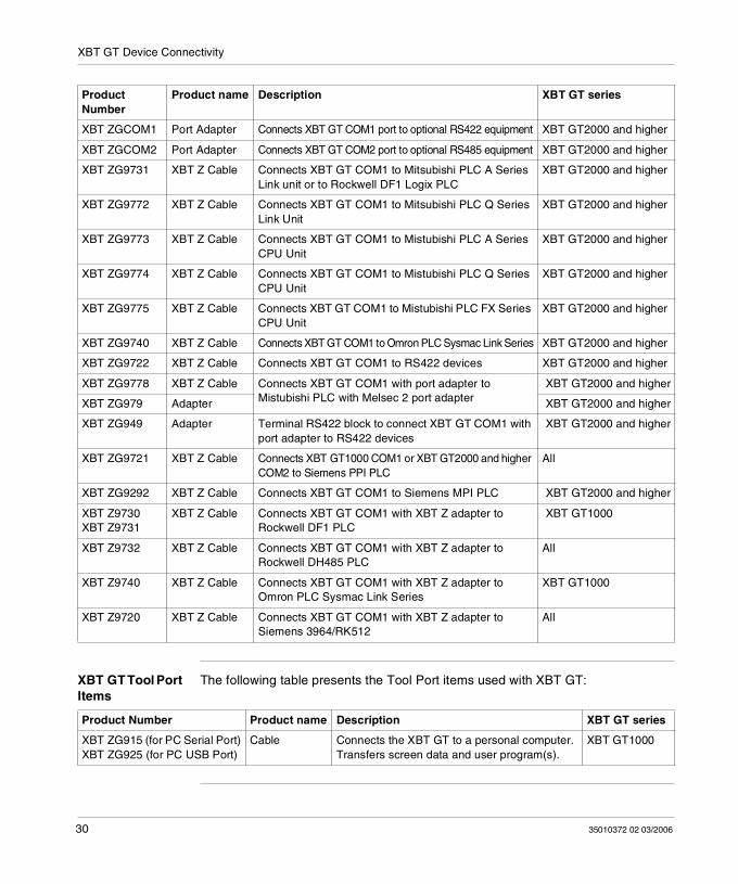
XBT GT Tool Port Items
The following table presents the Tool Port items used with XBT GT:
XBT ZGCOM1 Port Adapter Connects XBT GT COM1 port to optional RS422 equipment XBT GT2000 and higher
XBT ZGCOM2 Port Adapter Connects XBT GT COM2 port to optional RS485 equipment XBT GT2000 and higher
XBT ZG9731 XBT Z Cable Connects XBT GT COM1 to Mitsubishi PLC A Series Link unit or to Rockwell DF1 Logix PLC
XBT GT2000 and higher
XBT ZG9772 XBT Z Cable Connects XBT GT COM1 to Mitsubishi PLC Q Series Link Unit
XBT GT2000 and higher
XBT ZG9773 XBT Z Cable Connects XBT GT COM1 to Mistubishi PLC A Series CPU Unit
XBT GT2000 and higher
XBT ZG9774 XBT Z Cable Connects XBT GT COM1 to Mistubishi PLC Q Series CPU Unit
XBT GT2000 and higher
XBT ZG9775 XBT Z Cable Connects XBT GT COM1 to Mistubishi PLC FX Series CPU Unit
XBT GT2000 and higher
XBT ZG9740 XBT Z Cable Connects XBT GT COM1 to Omron PLC Sysmac Link Series XBT GT2000 and higher
XBT ZG9722 XBT Z Cable Connects XBT GT COM1 to RS422 devices XBT GT2000 and higher
XBT ZG9778 XBT Z Cable Connects XBT GT COM1 with port adapter to Mistubishi PLC with Melsec 2 port adapter
XBT GT2000 and higher
XBT ZG979 Adapter XBT GT2000 and higher
XBT ZG949 Adapter Terminal RS422 block to connect XBT GT COM1 with port adapter to RS422 devices
XBT GT2000 and higher
XBT ZG9721 XBT Z Cable Connects XBT GT1000 COM1 or XBT GT2000 and higher COM2 to Siemens PPI PLC
All
XBT ZG9292 XBT Z Cable Connects XBT GT COM1 to Siemens MPI PLC XBT GT2000 and higher
XBT Z9730XBT Z9731
XBT Z Cable Connects XBT GT COM1 with XBT Z adapter to Rockwell DF1 PLC
XBT GT1000
XBT Z9732 XBT Z Cable Connects XBT GT COM1 with XBT Z adapter to Rockwell DH485 PLC
All
XBT Z9740 XBT Z Cable Connects XBT GT COM1 with XBT Z adapter to Omron PLC Sysmac Link Series
XBT GT1000
XBT Z9720 XBT Z Cable Connects XBT GT COM1 with XBT Z adapter to Siemens 3964/RK512
All
Product Number
Product name Description XBT GT series
Product Number Product name Description XBT GT series
XBT ZG915 (for PC Serial Port)XBT ZG925 (for PC USB Port)
Cable Connects the XBT GT to a personal computer. Transfers screen data and user program(s).
XBT GT1000
30 35010372 02 03/2006
XBT GT Device Connectivity
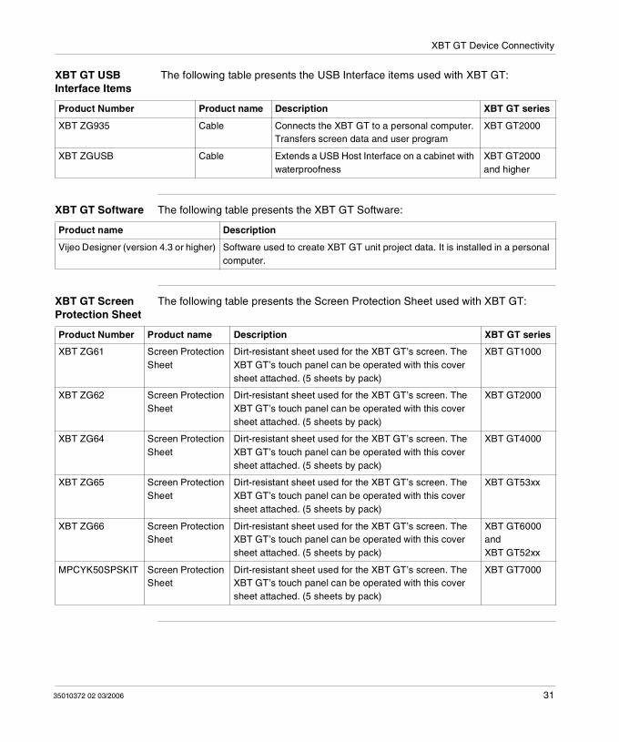
XBT GT USB Interface Items
The following table presents the USB Interface items used with XBT GT:
XBT GT Software The following table presents the XBT GT Software:
XBT GT Screen Protection Sheet
The following table presents the Screen Protection Sheet used with XBT GT:
Product Number Product name Description XBT GT series
XBT ZG935 Cable Connects the XBT GT to a personal computer. Transfers screen data and user program
XBT GT2000
XBT ZGUSB Cable Extends a USB Host Interface on a cabinet with waterproofness
XBT GT2000 and higher
Product name Description
Vijeo Designer (version 4.3 or higher) Software used to create XBT GT unit project data. It is installed in a personal computer.
Product Number Product name Description XBT GT series
XBT ZG61 Screen Protection Sheet
Dirt-resistant sheet used for the XBT GT’s screen. The XBT GT’s touch panel can be operated with this cover sheet attached. (5 sheets by pack)
XBT GT1000
XBT ZG62 Screen Protection Sheet
Dirt-resistant sheet used for the XBT GT’s screen. The XBT GT’s touch panel can be operated with this cover sheet attached. (5 sheets by pack)
XBT GT2000
XBT ZG64 Screen Protection Sheet
Dirt-resistant sheet used for the XBT GT’s screen. The XBT GT’s touch panel can be operated with this cover sheet attached. (5 sheets by pack)
XBT GT4000
XBT ZG65 Screen Protection Sheet
Dirt-resistant sheet used for the XBT GT’s screen. The XBT GT’s touch panel can be operated with this cover sheet attached. (5 sheets by pack)
XBT GT53xx
XBT ZG66 Screen Protection Sheet
Dirt-resistant sheet used for the XBT GT’s screen. The XBT GT’s touch panel can be operated with this cover sheet attached. (5 sheets by pack)
XBT GT6000 and XBT GT52xx
MPCYK50SPSKIT Screen Protection Sheet
Dirt-resistant sheet used for the XBT GT’s screen. The XBT GT’s touch panel can be operated with this cover sheet attached. (5 sheets by pack)
XBT GT7000
35010372 02 03/2006 31
XBT GT Device Connectivity
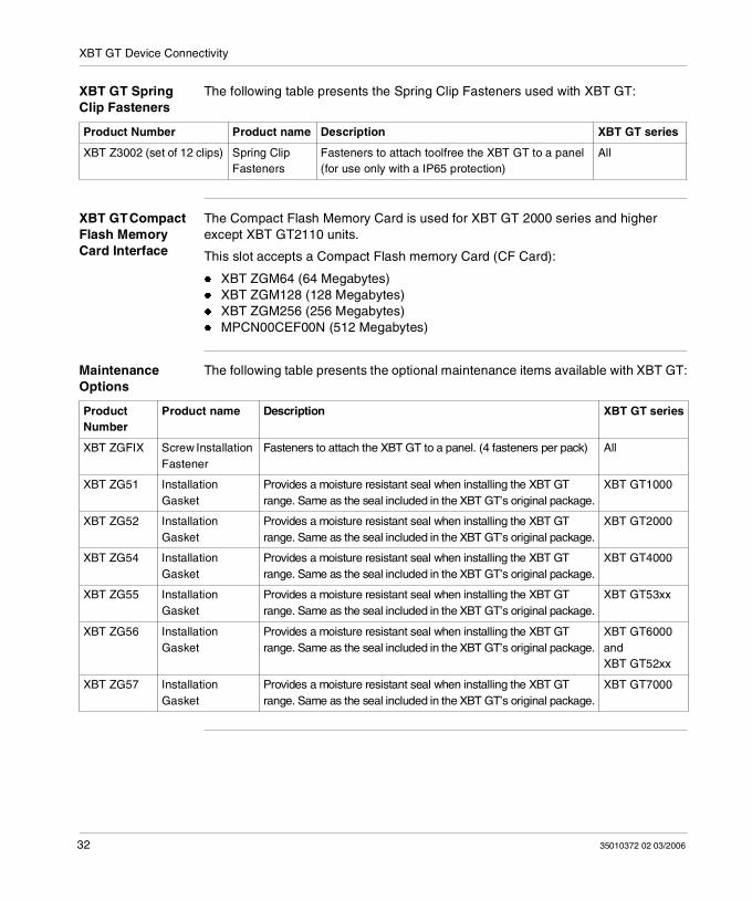
XBT GT Spring Clip Fasteners
The following table presents the Spring Clip Fasteners used with XBT GT:
XBT GT Compact Flash Memory Card Interface
The Compact Flash Memory Card is used for XBT GT 2000 series and higher except XBT GT2110 units.
This slot accepts a Compact Flash memory Card (CF Card):
XBT ZGM64 (64 Megabytes) XBT ZGM128 (128 Megabytes) XBT ZGM256 (256 Megabytes) MPCN00CEF00N (512 Megabytes)
Maintenance Options
The following table presents the optional maintenance items available with XBT GT:
Product Number Product name Description XBT GT series
XBT Z3002 (set of 12 clips) Spring Clip Fasteners
Fasteners to attach toolfree the XBT GT to a panel (for use only with a IP65 protection)
All
Product Number
Product name Description XBT GT series
XBT ZGFIX Screw Installation Fastener
Fasteners to attach the XBT GT to a panel. (4 fasteners per pack) All
XBT ZG51 Installation Gasket
Provides a moisture resistant seal when installing the XBT GT range. Same as the seal included in the XBT GT’s original package.
XBT GT1000
XBT ZG52 Installation Gasket
Provides a moisture resistant seal when installing the XBT GT range. Same as the seal included in the XBT GT’s original package.
XBT GT2000
XBT ZG54 Installation Gasket
Provides a moisture resistant seal when installing the XBT GT range. Same as the seal included in the XBT GT’s original package.
XBT GT4000
XBT ZG55 Installation Gasket
Provides a moisture resistant seal when installing the XBT GT range. Same as the seal included in the XBT GT’s original package.
XBT GT53xx
XBT ZG56 Installation Gasket
Provides a moisture resistant seal when installing the XBT GT range. Same as the seal included in the XBT GT’s original package.
XBT GT6000 and XBT GT52xx
XBT ZG57 Installation Gasket
Provides a moisture resistant seal when installing the XBT GT range. Same as the seal included in the XBT GT’s original package.
XBT GT7000
32 35010372 02 03/2006
35010372 02 03/2006
3
SpecificationsAt a Glance
Overview This chapter presents the different XBT GT specifications:
General Specifications Functional Specifications Interface Specifications Part Numbers and Functions Dimensions
What's in this Chapter?
This chapter contains the following sections:
Section Topic Page
3.1 General Specifications 35
3.2 Functional Specifications 41
3.3 Interface Specifications 49
3.4 Part Numbers and Functions 57
3.5 Dimensions 84
33
Specifications
34 35010372 02 03/2006
Specifications
3.1 General Specifications
At a Glance
Overview This section presents XBT GT general specifications:
Electrical Specifications Environmental Specifications Structural Specifications
What's in this Section?
This section contains the following topics:
Topic Page
Electrical Specifications 36
Environmental Specifications 37
Structural Specifications 39
35010372 02 03/2006 35
Specifications
Electrical Specifications
XBT GT Electrical Specifications
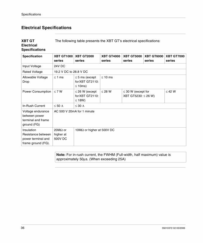
The following table presents the XBT GT’s electrical specifications:
Specification XBT GT1000 series
XBT GT2000 series
XBT GT4000 series
XBT GT5000 series
XBT GT6000 series
XBT GT7000 series
Input Voltage 24V DC
Rated Voltage 19.2 V DC to 28.8 V DC
Allowable Voltage Drop
≤ 1 ms ≤ 5 ms (except for XBT GT2110: ≤ 10ms)
≤ 10 ms
Power Consumption ≤ 7 W ≤ 26 W (except for XBT GT2110: ≤ 18W)
≤ 28 W ≤ 30 W (except for XBT GT5230: ≤ 26 W)
≤ 42 W
In-Rush Current ≤ 50 Α ≤ 30 Α
Voltage endurance between power terminal and frame ground (FG)
AC 500 V 20mA for 1 minute
Insulation Resistance between power terminal and frame ground (FG).
20MΩ or higher at 500V DC
10MΩ or higher at 500V DC
Note: For in-rush current, the FWHM (Full-width, half maximum) value is approximately 50µs. (When exceeding 25A)
36 35010372 02 03/2006
Specifications
Environmental Specifications
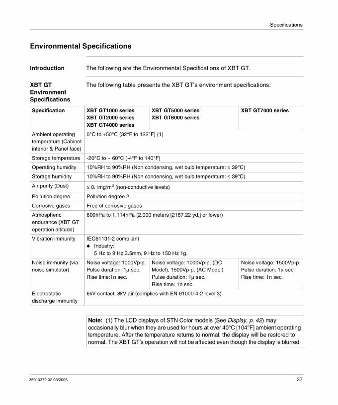
Introduction The following are the Environmental Specifications of XBT GT.
XBT GT Environment Specifications
The following table presents the XBT GT’s environment specifications:
Specification XBT GT1000 seriesXBT GT2000 seriesXBT GT4000 series
XBT GT5000 seriesXBT GT6000 series
XBT GT7000 series
Ambient operating temperature (Cabinet interior & Panel face)
0°C to +50°C (32°F to 122°F) (1)
Storage temperature -20°C to + 60°C (-4°F to 140°F)
Operating humidity 10%RH to 90%RH (Non condensing, wet bulb temperature: ≤ 39°C)
Storage humidity 10%RH to 90%RH (Non condensing, wet bulb temperature: ≤ 39°C)
Air purity (Dust) ≤ 0.1mg/m3 (non-conductive levels)
Pollution degree Pollution degree 2
Corrosive gases Free of corrosive gases
Atmospheric endurance (XBT GT operation altitude)
800hPa to 1,114hPa (2,000 meters [2187.22 yd.] or lower)
Vibration immunity IEC61131-2 compliant Industry:
5 Hz to 9 Hz 3.5mm, 9 Hz to 150 Hz 1g.
Noise immunity (via noise simulator)
Noise voltage: 1000Vp-p.Pulse duration: 1µ sec.Rise time:1n sec.
Noise voltage: 1000Vp-p. (DC Model), 1500Vp-p. (AC Model)Pulse duration: 1µ sec.Rise time: 1n sec.
Noise voltage: 1500Vp-p.Pulse duration: 1µ sec.Rise time: 1n sec.
Electrostatic discharge immunity
6kV contact, 8kV air (complies with EN 61000-4-2 level 3)
Note: (1) The LCD displays of STN Color models (See Display, p. 42) may occasionally blur when they are used for hours at over 40°C [104°F] ambient operating temperature. After the temperature returns to normal, the display will be restored to normal. The XBT GT’s operation will not be affected even though the display is blurred.
35010372 02 03/2006 37
Specifications
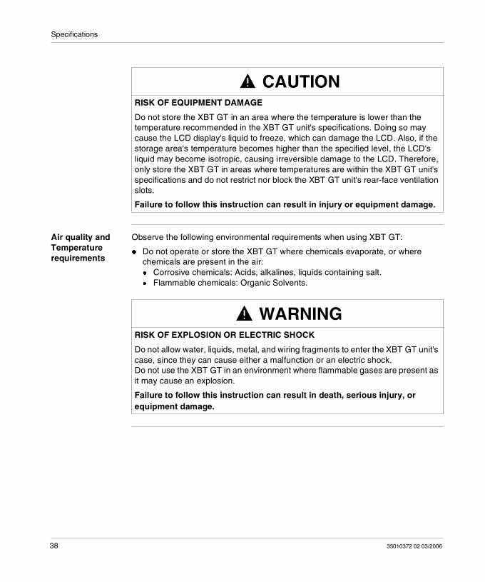
Air quality and Temperature requirements
Observe the following environmental requirements when using XBT GT:
Do not operate or store the XBT GT where chemicals evaporate, or where chemicals are present in the air: Corrosive chemicals: Acids, alkalines, liquids containing salt. Flammable chemicals: Organic Solvents.
CAUTIONRISK OF EQUIPMENT DAMAGE
Do not store the XBT GT in an area where the temperature is lower than the temperature recommended in the XBT GT unit's specifications. Doing so may cause the LCD display's liquid to freeze, which can damage the LCD. Also, if the storage area's temperature becomes higher than the specified level, the LCD's liquid may become isotropic, causing irreversible damage to the LCD. Therefore, only store the XBT GT in areas where temperatures are within the XBT GT unit's specifications and do not restrict nor block the XBT GT unit's rear-face ventilation slots.
Failure to follow this instruction can result in injury or equipment damage.
WARNINGRISK OF EXPLOSION OR ELECTRIC SHOCK
Do not allow water, liquids, metal, and wiring fragments to enter the XBT GT unit's case, since they can cause either a malfunction or an electric shock. Do not use the XBT GT in an environment where flammable gases are present as it may cause an explosion.
Failure to follow this instruction can result in death, serious injury, or equipment damage.
38 35010372 02 03/2006
Specifications
Structural Specifications
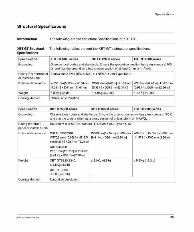
Introduction The following are the Structural Specifications of XBT GT.
XBT GT Structural Specifications
The following tables present the XBT GT’s structural specifications:
Specification XBT GT1000 series XBT GT2000 series XBT GT4000 series
Grounding Observe local codes and standards. Ensure the ground connection has a resistance ≤ 100 Ω and that the ground wire has a cross section of at least 2mm or 14AWG.
Rating (For front panel or installed unit)
Equivalent to IP65 (IEC 60529) (1) NEMA # 250 Type 4X/13
External dimensions W130 mm [5.12 in] x H104 mm [4.09 in] x D41 mm [1.61 in]
W167.4 mm [6.60 in] x H135 mm [5.32 in] x D59.5 mm [2.34 in]
W215 mm [8.46 in] x H170 mm [6.69 in] x D60 mm [2.36 in]
Weight ≤ 0.4Kg (0.9lb) ≤ 1.0Kg (2.20lb) ≤ 1.8Kg (4.0lb)
Cooling Method Natural air circulation
Specification XBT GT5000 series XBT GT6000 series XBT GT7000 series
Grounding Observe local codes and standards. Ensure the ground connection has a resistance ≤ 100 Ω and that the ground wire has a cross section of at least 2mm or 14AWG.
Rating (For front panel or installed unit)
Equivalent to IP65 (IEC 60529) (1) NEMA # 250 Type 4X/13
External dimensions XBT GT5330/5340: W270.5 mm [10.65in] x H212.5 mm [8.37 in] x D57 mm [2.24 in]
W313mm [12.32 in] x H239 mm [9.41 in] x D56 mm [2.20 in]
W395 mm [15.55 in] x H294 mm [11.57 in] x D60 mm [2.36 in]
XBT GT5230:W313 mm [12.32in] x H239 mm [9.41 in] x D56 mm [2.20 in]
Weight XBT GT5330/5340:≤ 2.5Kg (5.5lb)
≤ 3.0Kg (6.6lb) ≤ 5.6Kg (12.3lb)
XBT GT5230:≤ 3.0Kg (6.6lb)
Cooling Method Natural air circulation
35010372 02 03/2006 39
Specifications
Note: (1) The front face of the XBT GT unit, installed in a solid panel, has been tested using conditions equivalent to the standards shown in the specification. Therefore, prior to installing the XBT GT be sure to confirm the type of conditions that will be present in the XBT GT’s operating environment. If the installation gasket is used for a long period of time, or if the unit and its gasket are removed from the panel, the original level of the protection cannot be guaranteed. To maintain the original protection level, replace the installation gasket every year.
40 35010372 02 03/2006
Specifications
3.2 Functional Specifications
At a Glance
Overview This section presents XBT GT Functional Specifications:
Display Memory Interfaces
What's in this Section?
This section contains the following topics:
Topic Page
Display 42
Memory, Clock, and Touch Panel 45
Interface 47
35010372 02 03/2006 41
Specifications
Display
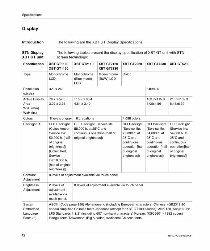
Introduction The following are the XBT GT Display Specifications.
STN Display XBT GT unit
The following tables present the display specification of XBT GT unit with STN screen technology:
Specification XBT GT1100XBT GT1130
XBT GT2110 XBT GT2120XBT GT2130
XBT GT2220 XBT GT4230 XBT GT5230
Type Monochrome LCD
Monochrome (Blue mode) LCD
Monochrome (B&W) LCD
Color
Resolution (pixels)
320 x 240 640x480
Active Display AreaWxH (mm)WxH (in.)
76.7 x 57.53.02 x 2.26
115.2 x 86.44.54 x 3.40
153.7x115.86.05x4.56
215.2x162.38.43x6.39
Colors 8 levels of gray 16 gradations 4.096 colors
Backlight (1) LED Backlight (Color: Amber; Service life: 50,000 h. [half of original brightness]) (Color: Red; Service life:10,000 h. [half of original brightness])
CFL Backlight (Service life: 58,000 h. at 25°C and continuous operation [half of original brightness])
CFL Backlight (Service life: 75,000 h. at 25°C and continuous operation [half of original brightness])
CFL Backlight (Service life: 54,000 h. at 25°C and continuous operation [half of original brightness])
CFL Backlight (Service life: 54,000 h. at 25°C and continuous operation [half of original brightness])
Contrast Adjustment
8 levels of adjustment available via touch panel.
Brightness Adjustment
2 levels of adjustment available via touch panel.
8 levels of adjustment available via touch panel.
System Embedded Language Fonts (2)
ASCII: (Code page 850) Alphanumeric (including European characters) Chinese: (GB2312-80 codes) simplified Chinese fonts Japanese (except for XBT GT1000 series): ANK 158, Kanji: 6,962 (JIS Standards 1 & 2) (including 607 non-kanji characters) Korean: (KSC5601 - 1992 codes) Hangul fonts Taiwanese: (Big 5 codes) traditional Chinese fonts
42 35010372 02 03/2006
Specifications
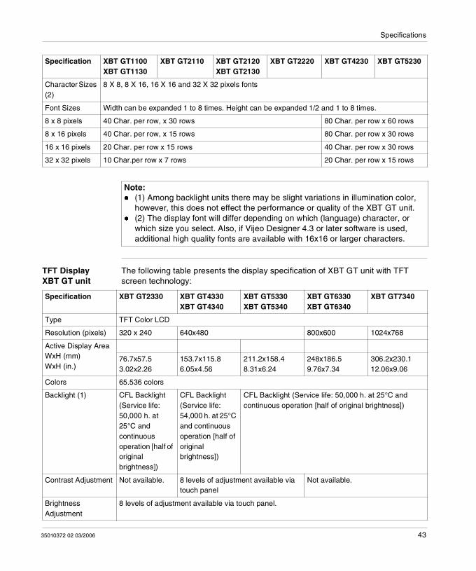
TFT Display XBT GT unit
The following table presents the display specification of XBT GT unit with TFT screen technology:
Character Sizes (2)
8 X 8, 8 X 16, 16 X 16 and 32 X 32 pixels fonts
Font Sizes Width can be expanded 1 to 8 times. Height can be expanded 1/2 and 1 to 8 times.
8 x 8 pixels 40 Char. per row, x 30 rows 80 Char. per row x 60 rows
8 x 16 pixels 40 Char. per row, x 15 rows 80 Char. per row x 30 rows
16 x 16 pixels 20 Char. per row x 15 rows 40 Char. per row x 30 rows
32 x 32 pixels 10 Char.per row x 7 rows 20 Char. per row x 15 rows
Specification XBT GT1100XBT GT1130
XBT GT2110 XBT GT2120XBT GT2130
XBT GT2220 XBT GT4230 XBT GT5230
Note: (1) Among backlight units there may be slight variations in illumination color,
however, this does not effect the performance or quality of the XBT GT unit. (2) The display font will differ depending on which (language) character, or
which size you select. Also, if Vijeo Designer 4.3 or later software is used, additional high quality fonts are available with 16x16 or larger characters.
Specification XBT GT2330 XBT GT4330XBT GT4340
XBT GT5330XBT GT5340
XBT GT6330XBT GT6340
XBT GT7340
Type TFT Color LCD
Resolution (pixels) 320 x 240 640x480 800x600 1024x768
Active Display AreaWxH (mm)WxH (in.)
76.7x57.53.02x2.26
153.7x115.86.05x4.56
211.2x158.48.31x6.24
248x186.59.76x7.34
306.2x230.112.06x9.06
Colors 65.536 colors
Backlight (1) CFL Backlight (Service life: 50,000 h. at 25°C and continuous operation [half of original brightness])
CFL Backlight (Service life: 54,000 h. at 25°C and continuous operation [half of original brightness])
CFL Backlight (Service life: 50,000 h. at 25°C and continuous operation [half of original brightness])
Contrast Adjustment Not available. 8 levels of adjustment available via touch panel
Not available.
Brightness Adjustment
8 levels of adjustment available via touch panel.
35010372 02 03/2006 43
Specifications
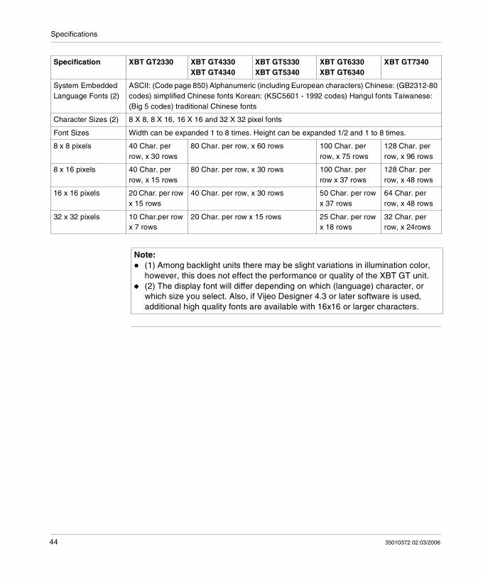
System Embedded Language Fonts (2)
ASCII: (Code page 850) Alphanumeric (including European characters) Chinese: (GB2312-80 codes) simplified Chinese fonts Korean: (KSC5601 - 1992 codes) Hangul fonts Taiwanese: (Big 5 codes) traditional Chinese fonts
Character Sizes (2) 8 X 8, 8 X 16, 16 X 16 and 32 X 32 pixel fonts
Font Sizes Width can be expanded 1 to 8 times. Height can be expanded 1/2 and 1 to 8 times.
8 x 8 pixels 40 Char. per row, x 30 rows
80 Char. per row, x 60 rows 100 Char. per row, x 75 rows
128 Char. per row, x 96 rows
8 x 16 pixels 40 Char. per row, x 15 rows
80 Char. per row, x 30 rows 100 Char. per row x 37 rows
128 Char. per row, x 48 rows
16 x 16 pixels 20 Char. per row x 15 rows
40 Char. per row, x 30 rows 50 Char. per row x 37 rows
64 Char. per row, x 48 rows
32 x 32 pixels 10 Char.per row x 7 rows
20 Char. per row x 15 rows 25 Char. per row x 18 rows
32 Char. per row, x 24rows
Specification XBT GT2330 XBT GT4330XBT GT4340
XBT GT5330XBT GT5340
XBT GT6330XBT GT6340
XBT GT7340
Note: (1) Among backlight units there may be slight variations in illumination color,
however, this does not effect the performance or quality of the XBT GT unit. (2) The display font will differ depending on which (language) character, or
which size you select. Also, if Vijeo Designer 4.3 or later software is used, additional high quality fonts are available with 16x16 or larger characters.
44 35010372 02 03/2006
Specifications
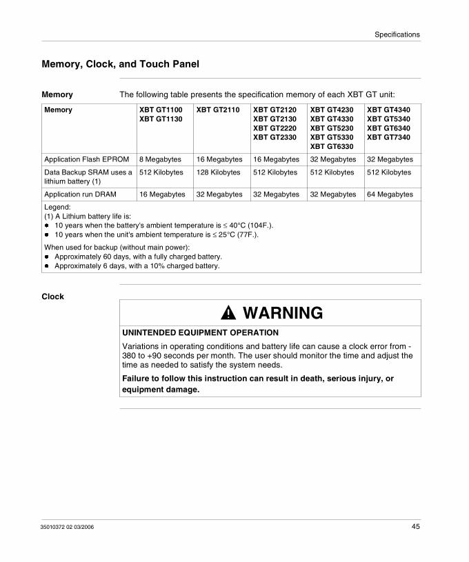
Memory, Clock, and Touch Panel
Memory The following table presents the specification memory of each XBT GT unit:
Clock
Memory XBT GT1100XBT GT1130
XBT GT2110 XBT GT2120XBT GT2130XBT GT2220XBT GT2330
XBT GT4230XBT GT4330XBT GT5230XBT GT5330XBT GT6330
XBT GT4340XBT GT5340XBT GT6340XBT GT7340
Application Flash EPROM 8 Megabytes 16 Megabytes 16 Megabytes 32 Megabytes 32 Megabytes
Data Backup SRAM uses a lithium battery (1)
512 Kilobytes 128 Kilobytes 512 Kilobytes 512 Kilobytes 512 Kilobytes
Application run DRAM 16 Megabytes 32 Megabytes 32 Megabytes 32 Megabytes 64 Megabytes
Legend:(1) A Lithium battery life is: 10 years when the battery's ambient temperature is ≤ 40°C (104F.). 10 years when the unit's ambient temperature is ≤ 25°C (77F.).
When used for backup (without main power): Approximately 60 days, with a fully charged battery. Approximately 6 days, with a 10% charged battery.
WARNINGUNINTENDED EQUIPMENT OPERATION
Variations in operating conditions and battery life can cause a clock error from -380 to +90 seconds per month. The user should monitor the time and adjust the time as needed to satisfy the system needs.
Failure to follow this instruction can result in death, serious injury, or equipment damage.
35010372 02 03/2006 45
Specifications
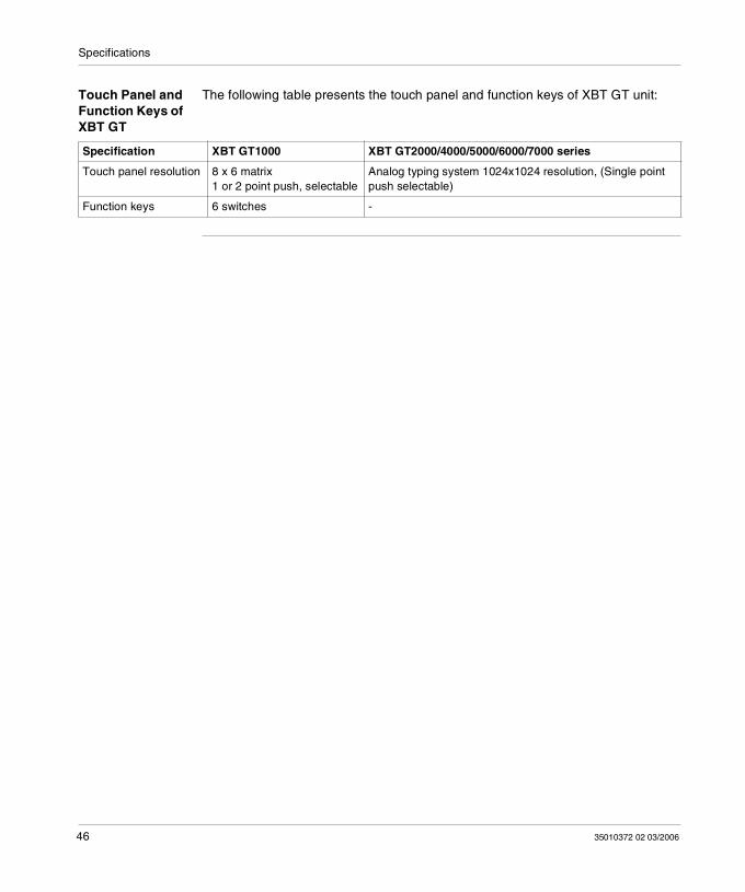
Touch Panel and Function Keys of XBT GT
The following table presents the touch panel and function keys of XBT GT unit:
Specification XBT GT1000 XBT GT2000/4000/5000/6000/7000 series
Touch panel resolution 8 x 6 matrix1 or 2 point push, selectable
Analog typing system 1024x1024 resolution, (Single point push selectable)
Function keys 6 switches -
46 35010372 02 03/2006
Specifications
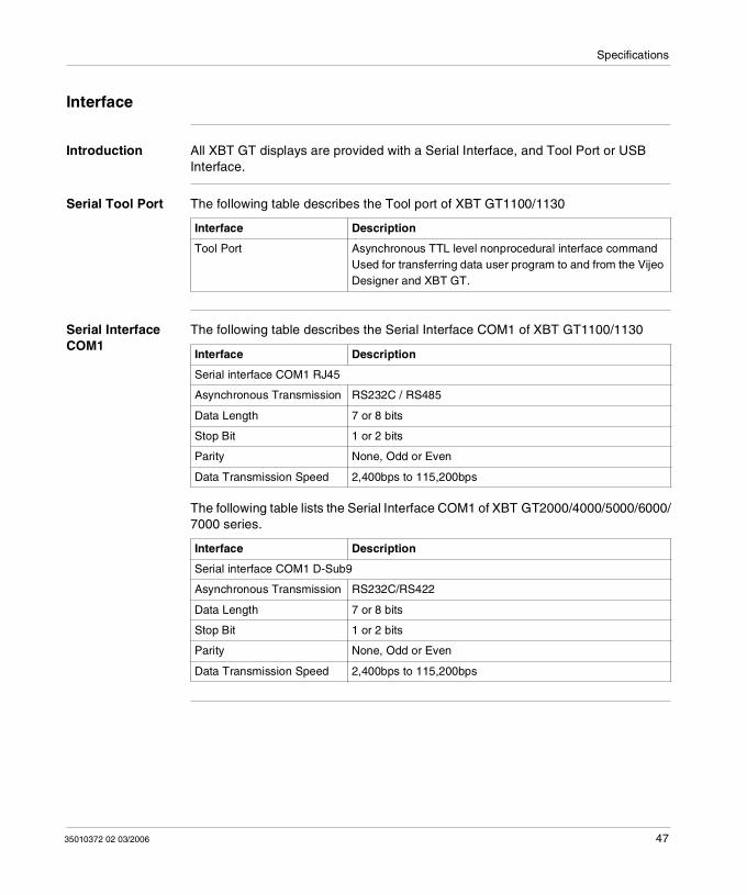
Interface
Introduction All XBT GT displays are provided with a Serial Interface, and Tool Port or USB Interface.
Serial Tool Port The following table describes the Tool port of XBT GT1100/1130
Serial Interface COM1
The following table describes the Serial Interface COM1 of XBT GT1100/1130
The following table lists the Serial Interface COM1 of XBT GT2000/4000/5000/6000/7000 series.
Interface Description
Tool Port Asynchronous TTL level nonprocedural interface commandUsed for transferring data user program to and from the Vijeo Designer and XBT GT.
Interface Description
Serial interface COM1 RJ45
Asynchronous Transmission RS232C / RS485
Data Length 7 or 8 bits
Stop Bit 1 or 2 bits
Parity None, Odd or Even
Data Transmission Speed 2,400bps to 115,200bps
Interface Description
Serial interface COM1 D-Sub9
Asynchronous Transmission RS232C/RS422
Data Length 7 or 8 bits
Stop Bit 1 or 2 bits
Parity None, Odd or Even
Data Transmission Speed 2,400bps to 115,200bps
35010372 02 03/2006 47
Specifications
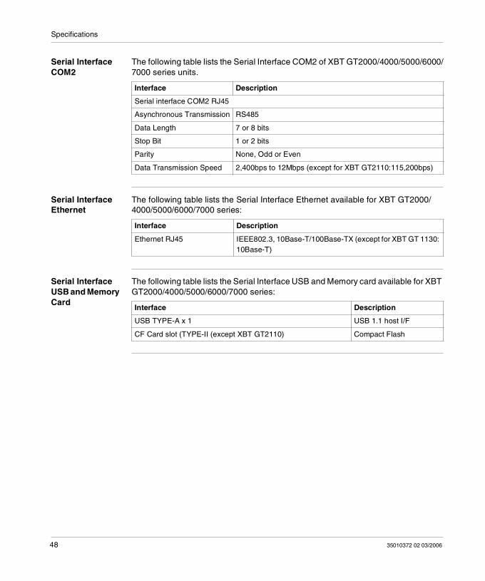
Serial Interface COM2
The following table lists the Serial Interface COM2 of XBT GT2000/4000/5000/6000/7000 series units.
Serial Interface Ethernet
The following table lists the Serial Interface Ethernet available for XBT GT2000/4000/5000/6000/7000 series:
Serial Interface USB and Memory Card
The following table lists the Serial Interface USB and Memory card available for XBT GT2000/4000/5000/6000/7000 series:
Interface Description
Serial interface COM2 RJ45
Asynchronous Transmission RS485
Data Length 7 or 8 bits
Stop Bit 1 or 2 bits
Parity None, Odd or Even
Data Transmission Speed 2,400bps to 12Mbps (except for XBT GT2110:115,200bps)
Interface Description
Ethernet RJ45 IEEE802.3, 10Base-T/100Base-TX (except for XBT GT 1130: 10Base-T)
Interface Description
USB TYPE-A x 1 USB 1.1 host I/F
CF Card slot (TYPE-II (except XBT GT2110) Compact Flash
48 35010372 02 03/2006
Specifications
3.3 Interface Specifications
At a Glance
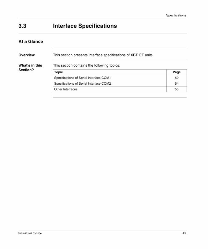
Overview This section presents interface specifications of XBT GT units.
What's in this Section?
This section contains the following topics:
Topic Page
Specifications of Serial Interface COM1 50
Specifications of Serial Interface COM2 54
Other Interfaces 55
35010372 02 03/2006 49
Specifications
Specifications of Serial Interface COM1
Introduction This interface is used to connect:
XBT GT1000 to remote equipment, via an RS232C or RS485 cable. The connector used is a RJ45-type connector.
XBT GT2000/4000/5000/6000/7000 series to remote equipment, via an RS232C or RS422 cable. The connector used is a D-Sub9 connector.
CAUTIONRISK OF ELECTRIC SHOCK
When connecting an external device to the XBT GT with the SG terminal, be sure to check that no short-circuit loop is created when you setup the system. The XBT GT unit’s Serial Port is not isolated. The #8 SG (XBT GT1100/1130
Signal Ground) terminal must be connected to remote equipment when the host (PLC) unit is not isolated. To reduce the risk of damaging the RS232C/RS485 circuit, make sure to connect the #8 SG (Signal Ground) terminal to the appropriate equipment.
The SG (Signal Ground) and the FG (Frame Ground) terminals are connected inside the XBT GT unit.
Failure to follow this instruction can result in injury or equipment damage.
50 35010372 02 03/2006
Specifications
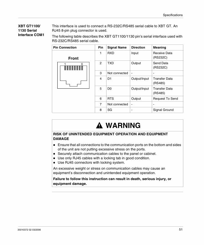
XBT GT1100/1130 Serial Interface COM1
This interface is used to connect a RS-232C/RS485 serial cable to XBT GT. An RJ45 8-pin plug connector is used.
The following table describes the XBT GT1100/1130 pin’s serial interface used with RS-232C/RS485 serial cable.
Pin Connection Pin Signal Name Direction Meaning
1 RXD Input Receive Data (RS232C)
2 TXD Output Send Data (RS232C)
3 Not connected - -
4 D1 Output/Input Transfer Data (RS485)
5 D0 Output/Input Transfer Data (RS485)
6 RTS Output Request To Send
7 Not connected - -
8 SG - Signal Ground
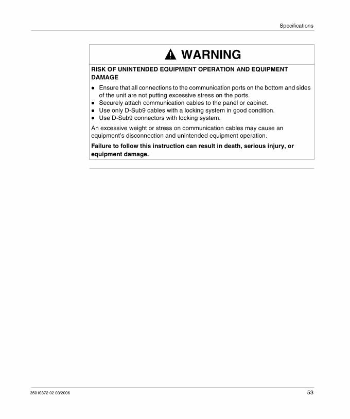
WARNINGRISK OF UNINTENDED EQUIPMENT OPERATION AND EQUIPMENT DAMAGE
Ensure that all connections to the communication ports on the bottom and sides of the unit are not putting excessive stress on the ports.
Securely attach communication cables to the panel or cabinet. Use only RJ45 cables with a locking tab in good condition. Use RJ45 connectors with locking system.
An excessive weight or stress on communication cables may cause an equipment’s disconnection and unintended equipment operation.
Failure to follow this instruction can result in death, serious injury, or equipment damage.
Front
35010372 02 03/2006 51
Specifications
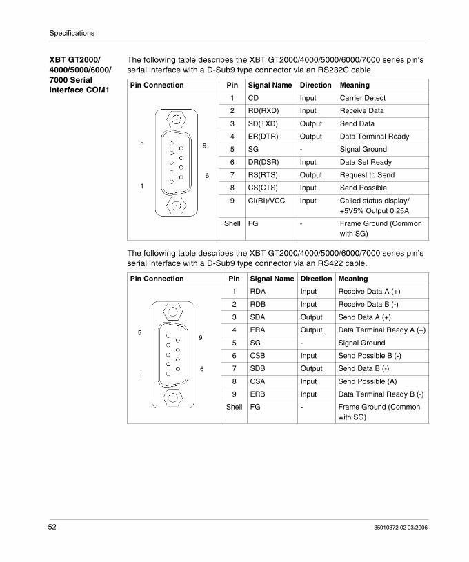
XBT GT2000/4000/5000/6000/7000 Serial Interface COM1
The following table describes the XBT GT2000/4000/5000/6000/7000 series pin’s serial interface with a D-Sub9 type connector via an RS232C cable.
The following table describes the XBT GT2000/4000/5000/6000/7000 series pin’s serial interface with a D-Sub9 type connector via an RS422 cable.
Pin Connection Pin Signal Name Direction Meaning
1 CD Input Carrier Detect
2 RD(RXD) Input Receive Data
3 SD(TXD) Output Send Data
4 ER(DTR) Output Data Terminal Ready
5 SG - Signal Ground
6 DR(DSR) Input Data Set Ready
7 RS(RTS) Output Request to Send
8 CS(CTS) Input Send Possible
9 CI(RI)/VCC Input Called status display/+5V5% Output 0.25A
Shell FG - Frame Ground (Common with SG)
Pin Connection Pin Signal Name Direction Meaning
1 RDA Input Receive Data A (+)
2 RDB Input Receive Data B (-)
3 SDA Output Send Data A (+)
4 ERA Output Data Terminal Ready A (+)
5 SG - Signal Ground
6 CSB Input Send Possible B (-)
7 SDB Output Send Data B (-)
8 CSA Input Send Possible (A)
9 ERB Input Data Terminal Ready B (-)
Shell FG - Frame Ground (Common with SG)
6
5
1
9
5
1
9
6
52 35010372 02 03/2006
Specifications
WARNINGRISK OF UNINTENDED EQUIPMENT OPERATION AND EQUIPMENT DAMAGE
Ensure that all connections to the communication ports on the bottom and sides of the unit are not putting excessive stress on the ports.
Securely attach communication cables to the panel or cabinet. Use only D-Sub9 cables with a locking system in good condition. Use D-Sub9 connectors with locking system.
An excessive weight or stress on communication cables may cause an equipment’s disconnection and unintended equipment operation.
Failure to follow this instruction can result in death, serious injury, or equipment damage.
35010372 02 03/2006 53
Specifications
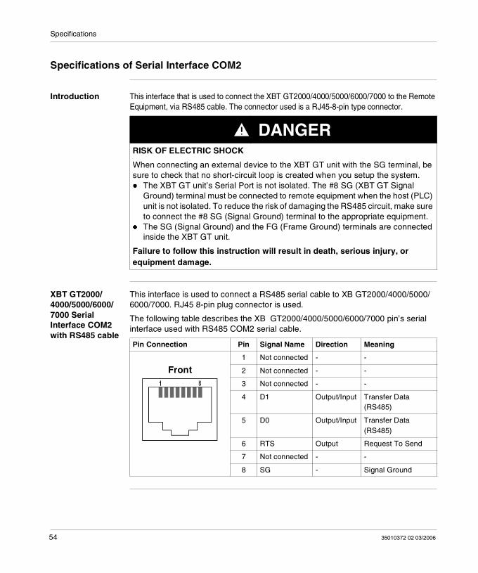
Specifications of Serial Interface COM2
Introduction This interface that is used to connect the XBT GT2000/4000/5000/6000/7000 to the Remote Equipment, via RS485 cable. The connector used is a RJ45-8-pin type connector.
XBT GT2000/4000/5000/6000/7000 Serial Interface COM2 with RS485 cable
This interface is used to connect a RS485 serial cable to XB GT2000/4000/5000/6000/7000. RJ45 8-pin plug connector is used.
The following table describes the XB GT2000/4000/5000/6000/7000 pin’s serial interface used with RS485 COM2 serial cable.
DANGERRISK OF ELECTRIC SHOCK
When connecting an external device to the XBT GT unit with the SG terminal, be sure to check that no short-circuit loop is created when you setup the system. The XBT GT unit’s Serial Port is not isolated. The #8 SG (XBT GT Signal
Ground) terminal must be connected to remote equipment when the host (PLC) unit is not isolated. To reduce the risk of damaging the RS485 circuit, make sure to connect the #8 SG (Signal Ground) terminal to the appropriate equipment.
The SG (Signal Ground) and the FG (Frame Ground) terminals are connected inside the XBT GT unit.
Failure to follow this instruction will result in death, serious injury, or equipment damage.
Pin Connection Pin Signal Name Direction Meaning
1 Not connected - -
2 Not connected - -
3 Not connected - -
4 D1 Output/Input Transfer Data (RS485)
5 D0 Output/Input Transfer Data (RS485)
6 RTS Output Request To Send
7 Not connected - -
8 SG - Signal Ground
Front
54 35010372 02 03/2006
Specifications
Other Interfaces
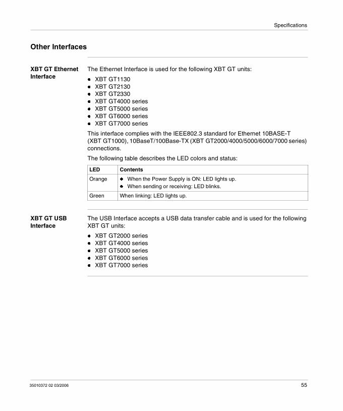
XBT GT Ethernet Interface
The Ethernet Interface is used for the following XBT GT units:
XBT GT1130 XBT GT2130 XBT GT2330 XBT GT4000 series XBT GT5000 series XBT GT6000 series XBT GT7000 series
This interface complies with the IEEE802.3 standard for Ethernet 10BASE-T (XBT GT1000), 10BaseT/100Base-TX (XBT GT2000/4000/5000/6000/7000 series) connections.
The following table describes the LED colors and status:
XBT GT USB Interface
The USB Interface accepts a USB data transfer cable and is used for the following XBT GT units:
XBT GT2000 series XBT GT4000 series XBT GT5000 series XBT GT6000 series XBT GT7000 series
LED Contents
Orange When the Power Supply is ON: LED lights up. When sending or receiving: LED blinks.
Green When linking: LED lights up.
35010372 02 03/2006 55
Specifications
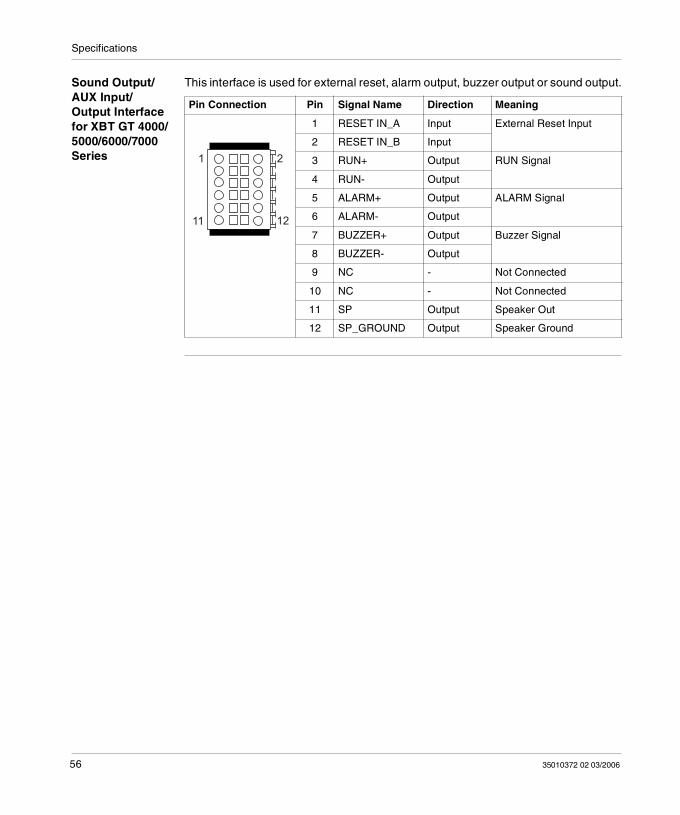
Sound Output/AUX Input/Output Interface for XBT GT 4000/5000/6000/7000 Series
This interface is used for external reset, alarm output, buzzer output or sound output.
Pin Connection Pin Signal Name Direction Meaning
1 RESET IN_A Input External Reset Input
2 RESET IN_B Input
3 RUN+ Output RUN Signal
4 RUN- Output
5 ALARM+ Output ALARM Signal
6 ALARM- Output
7 BUZZER+ Output Buzzer Signal
8 BUZZER- Output
9 NC - Not Connected
10 NC - Not Connected
11 SP Output Speaker Out
12 SP_GROUND Output Speaker Ground
1
11
2
12
56 35010372 02 03/2006
Specifications
3.4 Part Numbers and Functions
At a Glance
Overview This section presents the Part Number and Functions of XBT GT unit.
What's in this Section?
This section contains the following topics:
Topic Page
Parts Identification and Functions 58
Terminal Configuration Switches 80
35010372 02 03/2006 57
Specifications
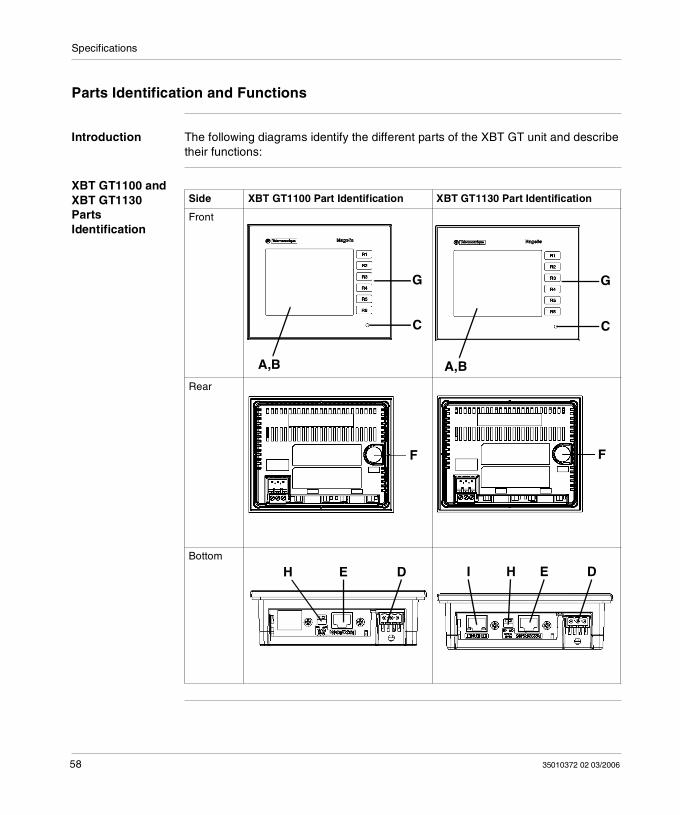
Parts Identification and Functions
Introduction The following diagrams identify the different parts of the XBT GT unit and describe their functions:
XBT GT1100 and XBT GT1130 Parts Identification
Side XBT GT1100 Part Identification XBT GT1130 Part Identification
Front
Rear
Bottom
A,B
G
C
A,B
G
C
F F
H E D DEHI
58 35010372 02 03/2006
Specifications
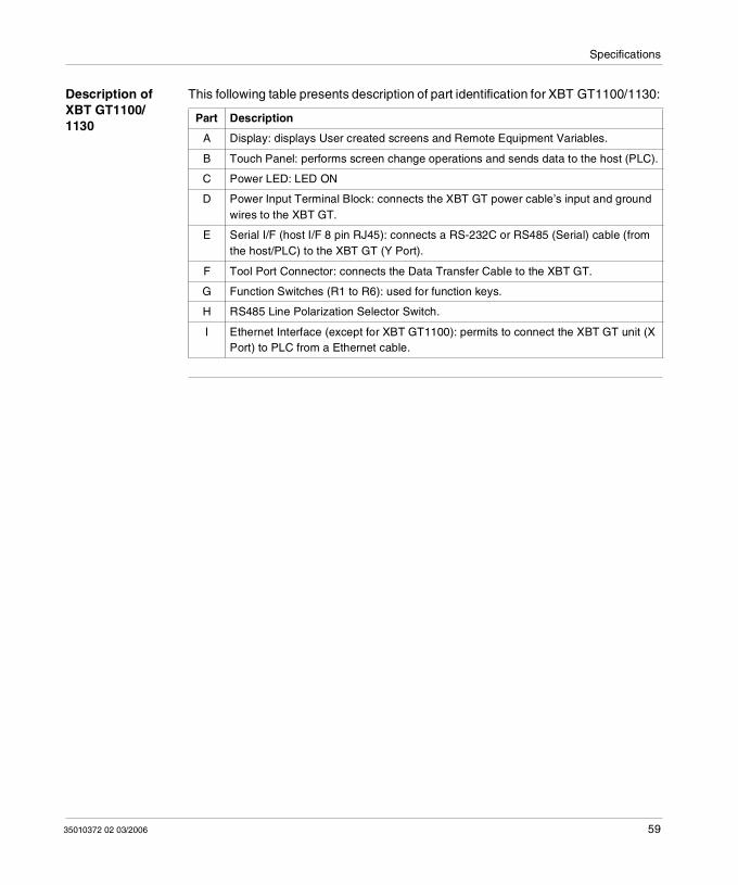
Description of XBT GT1100/1130
This following table presents description of part identification for XBT GT1100/1130:
Part Description
A Display: displays User created screens and Remote Equipment Variables.
B Touch Panel: performs screen change operations and sends data to the host (PLC).
C Power LED: LED ON
D Power Input Terminal Block: connects the XBT GT power cable’s input and ground wires to the XBT GT.
E Serial I/F (host I/F 8 pin RJ45): connects a RS-232C or RS485 (Serial) cable (from the host/PLC) to the XBT GT (Y Port).
F Tool Port Connector: connects the Data Transfer Cable to the XBT GT.
G Function Switches (R1 to R6): used for function keys.
H RS485 Line Polarization Selector Switch.
I Ethernet Interface (except for XBT GT1100): permits to connect the XBT GT unit (X Port) to PLC from a Ethernet cable.
35010372 02 03/2006 59
Specifications
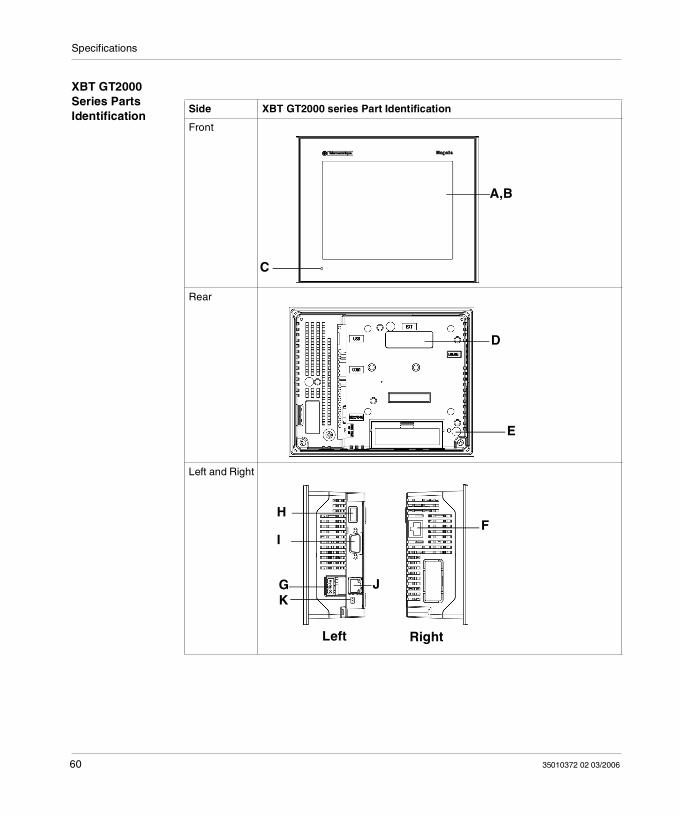
XBT GT2000 Series Parts Identification
Side XBT GT2000 series Part Identification
Front
Rear
Left and Right
A,B
C
D
E
H
I
G J
F
K
Left Right
60 35010372 02 03/2006
Specifications
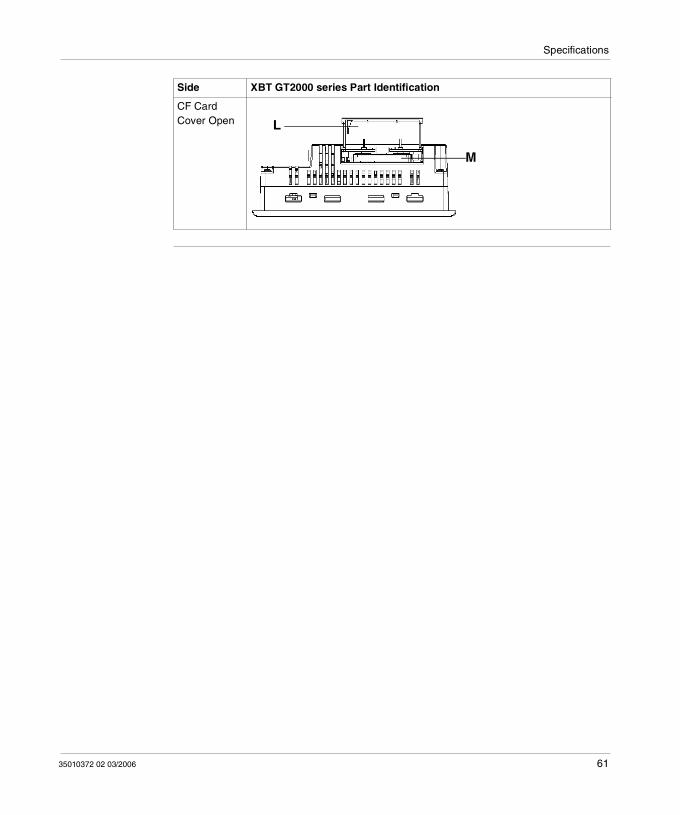
CF Card Cover Open
Side XBT GT2000 series Part Identification
M
L
35010372 02 03/2006 61

Specifications
Description of XBT GT2000 series
This following table describes the parts identification of XBT GT2000 series:
Part Description
A Display: displays User created screens and Remote Equipment Variables.
B Touch Panel: performs screen change operations and sends data to the host (PLC).
C Status LED: Green (lit): Normal operation (Power is ON) or OFFLINE operation. Orange (lit) (Green + red): Backlight burnout is detected. Orange (blinking) (Green + Red): During Software startup. Red (lit): When Power is turned ON Not lit: Power is OFF
D Expansion unit Interface: Connects expansion units with communication features.
E CF Card Access Lamp (except XBT GT2110): Green ON: The CF Card is inserted and the Cover is closed, or the CF Card is
being accessed. Green OFF: The CF Card is not inserted or is not being accessed.
F Ethernet Interface (10BASE-T/100BASE-TX) (except XBT GT2110/2220): RJ-45 connector is used, and the LED turns ON or OFF to indicate the current status. Green ON: Data transmission available. Green OFF: No connection or subsequent transmission failure. Yellow ON: Data transmission is occurring. Yellow OFF: No data transmission.
G Power Input Terminal Block: connects the XBT GT power cable’s input and ground wires to the XBT GT.
H USB Interface (USB1.1): Connects a data transfer cable to XBT GT.
I Serial Interface COM1: Connects a RS232C or RS422 (Serial) cable (from the host PLC) to the XBT GT (COM1 port).
J Serial Interface COM2: Connects a RS485 (Serial) cable (from the host PLC) to the XBT GT (COM2 port).
K RS485 Line Polarization Switch Selector.
L CF Card Cover: Covers the CF Card Slot. This cover must be closed when accessing to the CF Card (See XBT GT Location of CF Card Dip Switches, p. 80.)
M CF Card Socket: Permits to insert the CF Card in this slot.
62 35010372 02 03/2006
Specifications
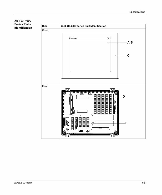
XBT GT4000 Series Parts Identification
Side XBT GT4000 series Part Identification
Front
Rear
A,B
C
D
E
35010372 02 03/2006 63
Specifications
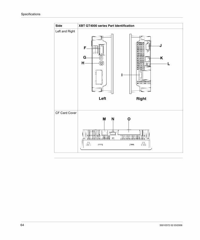
Left and Right
CF Card Cover
Side XBT GT4000 series Part Identification
H
I
G
JF
K
Left Right
L
M N O
64 35010372 02 03/2006
Specifications
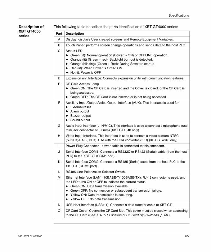
Description of XBT GT4000 series
This following table describes the parts identification of XBT GT4000 series:
Part Description
A Display: displays User created screens and Remote Equipment Variables.
B Touch Panel: performs screen change operations and sends data to the host PLC.
C Status LED: Green (lit): Normal operation (Power is ON) or OFFLINE operation. Orange (lit) (Green + red): Backlight burnout is detected. Orange (blinking) (Green + Red): During Software startup. Red (lit): When Power is turned ON Not lit: Power is OFF
D Expansion unit Interface: Connects expansion units with communication features.
E CF Card Access Lamp Green ON: The CF Card is inserted and the Cover is closed, or the CF Card is
being accessed. Green OFF: The CF Card is not inserted or is not being accessed.
F Auxiliary Input/Output/Voice Output Interface (AUX). This interface is used for: External reset Alarm output Buzzer output Sound output
G Audio Input Interface (L-IN/MIC). This interface is used to connect a microphone (use mini jack connector of 3.5mm) (XBT GT4340 only).
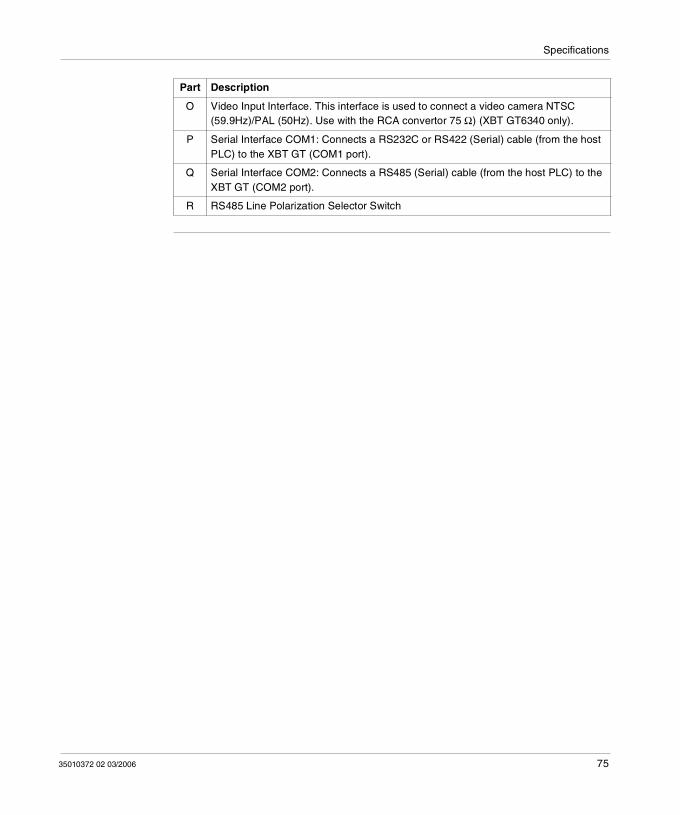
H Video Input Interface. This interface is used to connect a video camera NTSC (59.9Hz)/PAL (50Hz). Use with the RCA convertor 75 Ω) (XBT GT4340 only).
I Power Plug Connector - power cable is connected to this connector.
J Serial Interface COM1: Connects a RS232C or RS422 (Serial) cable (from the host PLC) to the XBT GT (COM1 port).
K Serial Interface COM2: Connects a RS485 (Serial) cable from the host PLC to the XBT GT (COM2 port).
L RS485 Line Polarization Selector Switch.
M Ethernet Interface (LAN) (10BASE-T/100BASE-TX): RJ-45 connector is used, and the LED turns ON or OFF to indicate the current status. Green ON: Data transmission available. Green OFF: No connection or subsequent transmission failure. Yellow ON: Data transmission is occurring. Yellow OFF: No data transmission.
N USB Host Interface (USB1.1): Connects a data transfer cable to XBT GT.
O CF Card Cover: Covers the CF Card Slot. This cover must be closed when accessing to the CF Card (See XBT GT Location of CF Card Dip Switches, p. 80.)
35010372 02 03/2006 65
Specifications
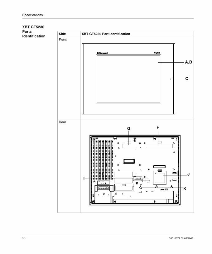
XBT GT5230 Parts Identification
Side XBT GT5230 Part Identification
Front
Rear
A,B
C
G H
IJ
K
66 35010372 02 03/2006
Specifications
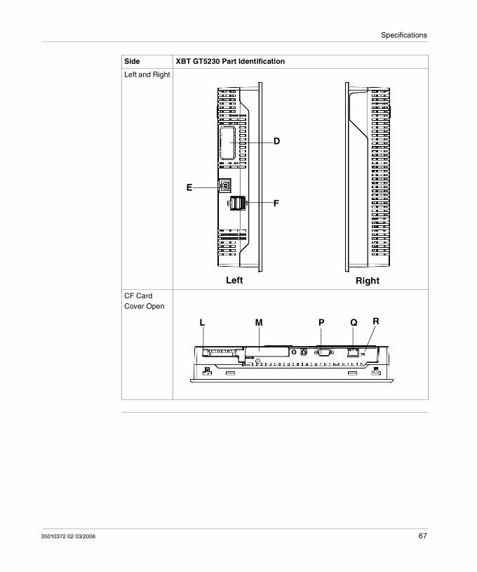
Left and Right
CF Card Cover Open
Side XBT GT5230 Part Identification
D
Left Right
E
F
ML P Q R
35010372 02 03/2006 67
Specifications
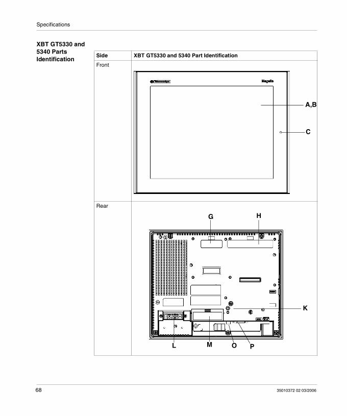
XBT GT5330 and 5340 Parts Identification
Side XBT GT5330 and 5340 Part Identification
Front
Rear
A,B
C
G H
K
ML O P
68 35010372 02 03/2006
Specifications
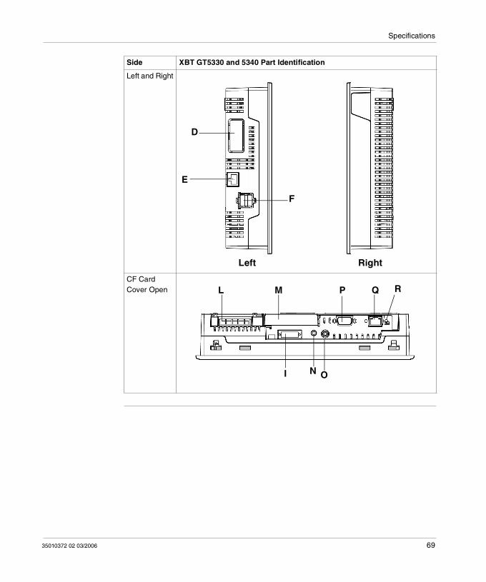
Left and Right
CF Card Cover Open
Side XBT GT5330 and 5340 Part Identification
D
F
E
RightLeft
ML P Q R
I N O
35010372 02 03/2006 69
Specifications
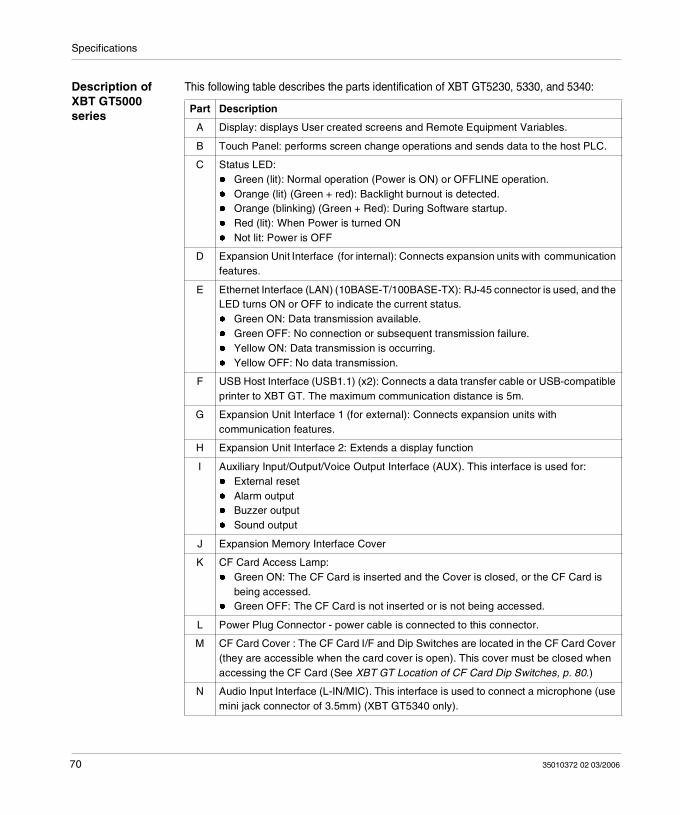
Description of XBT GT5000 series
This following table describes the parts identification of XBT GT5230, 5330, and 5340:
Part Description
A Display: displays User created screens and Remote Equipment Variables.
B Touch Panel: performs screen change operations and sends data to the host PLC.
C Status LED: Green (lit): Normal operation (Power is ON) or OFFLINE operation. Orange (lit) (Green + red): Backlight burnout is detected. Orange (blinking) (Green + Red): During Software startup. Red (lit): When Power is turned ON Not lit: Power is OFF
D Expansion Unit Interface (for internal): Connects expansion units with communication features.
E Ethernet Interface (LAN) (10BASE-T/100BASE-TX): RJ-45 connector is used, and the LED turns ON or OFF to indicate the current status. Green ON: Data transmission available. Green OFF: No connection or subsequent transmission failure. Yellow ON: Data transmission is occurring. Yellow OFF: No data transmission.
F USB Host Interface (USB1.1) (x2): Connects a data transfer cable or USB-compatible printer to XBT GT. The maximum communication distance is 5m.
G Expansion Unit Interface 1 (for external): Connects expansion units with communication features.
H Expansion Unit Interface 2: Extends a display function
I Auxiliary Input/Output/Voice Output Interface (AUX). This interface is used for: External reset Alarm output Buzzer output Sound output
J Expansion Memory Interface Cover
K CF Card Access Lamp: Green ON: The CF Card is inserted and the Cover is closed, or the CF Card is
being accessed. Green OFF: The CF Card is not inserted or is not being accessed.
L Power Plug Connector - power cable is connected to this connector.
M CF Card Cover : The CF Card I/F and Dip Switches are located in the CF Card Cover (they are accessible when the card cover is open). This cover must be closed when accessing the CF Card (See XBT GT Location of CF Card Dip Switches, p. 80.)
N Audio Input Interface (L-IN/MIC). This interface is used to connect a microphone (use mini jack connector of 3.5mm) (XBT GT5340 only).
70 35010372 02 03/2006
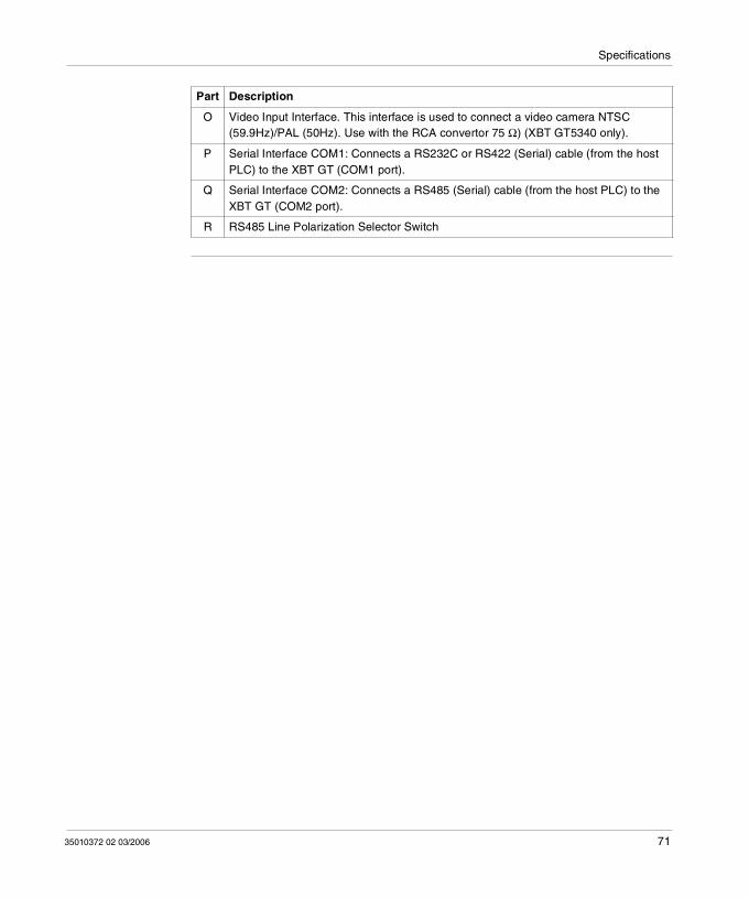
Specifications
O Video Input Interface. This interface is used to connect a video camera NTSC (59.9Hz)/PAL (50Hz). Use with the RCA convertor 75 Ω) (XBT GT5340 only).
P Serial Interface COM1: Connects a RS232C or RS422 (Serial) cable (from the host PLC) to the XBT GT (COM1 port).
Q Serial Interface COM2: Connects a RS485 (Serial) cable (from the host PLC) to the XBT GT (COM2 port).
R RS485 Line Polarization Selector Switch
Part Description
35010372 02 03/2006 71
Specifications
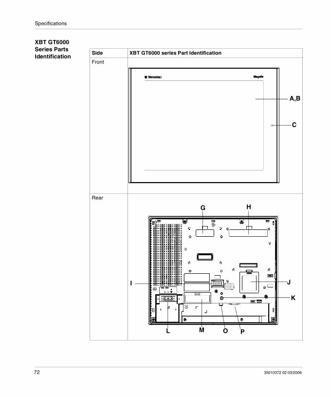
XBT GT6000 Series Parts Identification
Side XBT GT6000 series Part Identification
Front
Rear
A,B
C
G H
K
ML O P
JI
72 35010372 02 03/2006
Specifications
Left and Right
CF Card Cover Open
Side XBT GT6000 series Part Identification
D
F
E
RightLeft
ML P Q R
N O
35010372 02 03/2006 73

Specifications
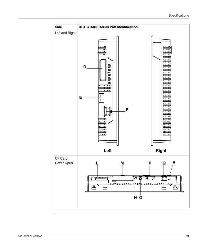
Description of XBT GT6000 series
This following table describes the parts identification of XBT GT6000 series:
Part Description
A Display: displays User created screens and Remote Equipment Variables.
B Touch Panel: performs screen change operations and sends data to the host PLC.
C Status LED: Green (lit): Normal operation (Power is ON) or OFFLINE operation. Orange (lit) (Green + red): Backlight burnout is detected. Orange (blinking) (Green + Red): During Software startup. Red (lit): When Power is turned ON Not lit: Power is OFF
D Expansion Unit Interface (for internal): Connects expansion units with communication features.
E Ethernet Interface (LAN) (10BASE-T/100BASE-TX): RJ-45 connector is used, and the LED turns ON or OFF to indicate the current status. Green ON: Data transmission available. Green OFF: No connection or subsequent transmission failure. Yellow ON: Data transmission is occurring. Yellow OFF: No data transmission.
F USB Host Interface (USB1.1) (x2): Connects a data transfer cable or USB-compatible printer to XBT GT. The maximum communication distance is 5m.
G Expansion Unit Interface 1 (for external): Connects expansion units with communication features.
H Expansion Unit Interface 2: Extends a display function
I Auxiliary Input/Output/Voice Output Interface (AUX). This interface is used for: External reset Alarm output Buzzer output Sound output
J Expansion Memory Interface Cover
K CF Card Access Lamp: Green ON: The CF Card is inserted and the Cover is closed, or the CF Card is
being accessed. Green OFF: The CF Card is not inserted or is not being accessed.
L Power Plug Connector - power cable is connected to this connector.
M CF Card Cover : The CF Card I/F and Dip Switches are located in the CF Card Cover (they are accessible when the card cover is open). This cover must be closed when accessing the CF Card (See XBT GT Location of CF Card Dip Switches, p. 80.)
N Audio Input Interface (L-IN/MIC). This interface is used to connect a microphone (use mini jack connector of 3.5mm) (XBT GT6340 only).
74 35010372 02 03/2006
Specifications
O Video Input Interface. This interface is used to connect a video camera NTSC (59.9Hz)/PAL (50Hz). Use with the RCA convertor 75 Ω) (XBT GT6340 only).
P Serial Interface COM1: Connects a RS232C or RS422 (Serial) cable (from the host PLC) to the XBT GT (COM1 port).
Q Serial Interface COM2: Connects a RS485 (Serial) cable (from the host PLC) to the XBT GT (COM2 port).
R RS485 Line Polarization Selector Switch
Part Description
35010372 02 03/2006 75
Specifications
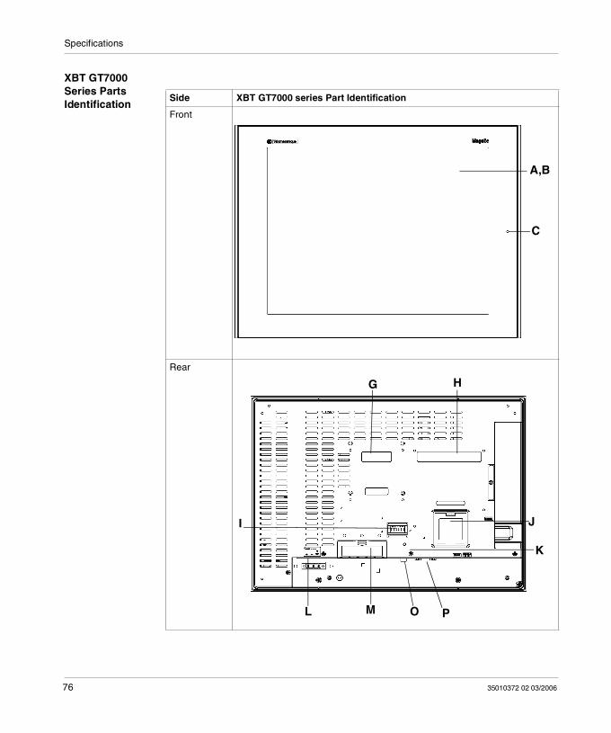
XBT GT7000 Series Parts Identification
Side XBT GT7000 series Part Identification
Front
Rear
A,B
C
G H
K
ML O P
JI
76 35010372 02 03/2006
Specifications
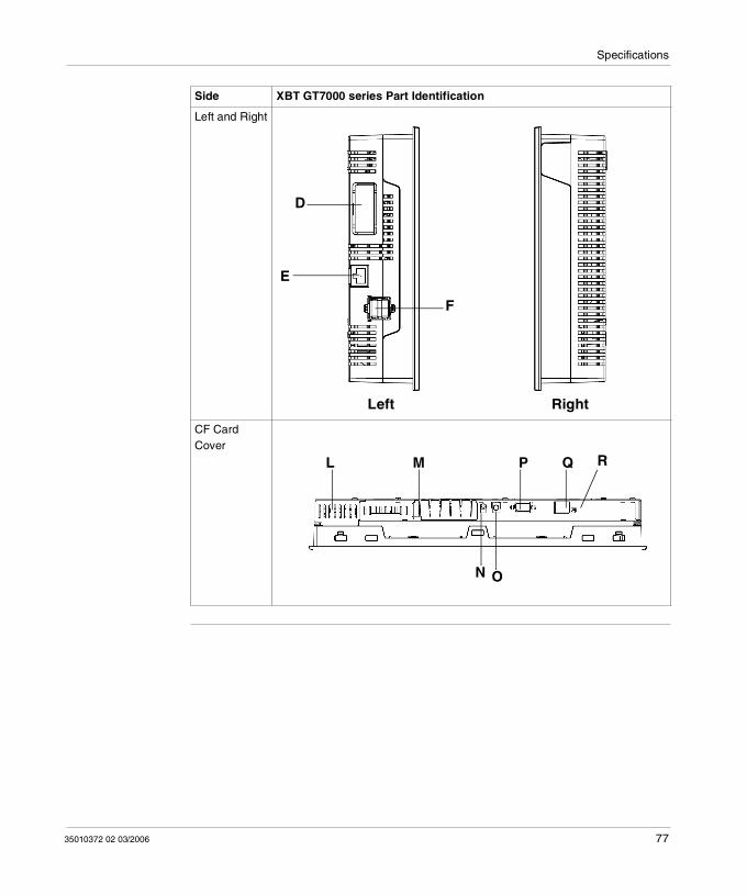
Left and Right
CF Card Cover
Side XBT GT7000 series Part Identification
D
F
E
RightLeft
ML P Q R
N O
35010372 02 03/2006 77
Specifications
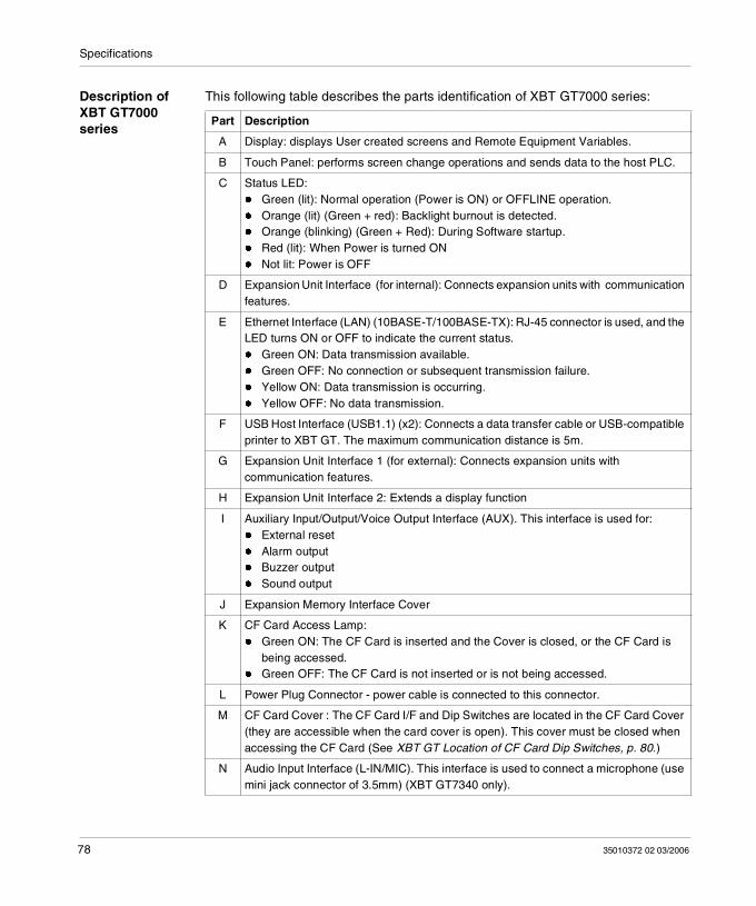
Description of XBT GT7000 series
This following table describes the parts identification of XBT GT7000 series:
Part Description
A Display: displays User created screens and Remote Equipment Variables.
B Touch Panel: performs screen change operations and sends data to the host PLC.
C Status LED: Green (lit): Normal operation (Power is ON) or OFFLINE operation. Orange (lit) (Green + red): Backlight burnout is detected. Orange (blinking) (Green + Red): During Software startup. Red (lit): When Power is turned ON Not lit: Power is OFF
D Expansion Unit Interface (for internal): Connects expansion units with communication features.
E Ethernet Interface (LAN) (10BASE-T/100BASE-TX): RJ-45 connector is used, and the LED turns ON or OFF to indicate the current status. Green ON: Data transmission available. Green OFF: No connection or subsequent transmission failure. Yellow ON: Data transmission is occurring. Yellow OFF: No data transmission.
F USB Host Interface (USB1.1) (x2): Connects a data transfer cable or USB-compatible printer to XBT GT. The maximum communication distance is 5m.
G Expansion Unit Interface 1 (for external): Connects expansion units with communication features.
H Expansion Unit Interface 2: Extends a display function
I Auxiliary Input/Output/Voice Output Interface (AUX). This interface is used for: External reset Alarm output Buzzer output Sound output
J Expansion Memory Interface Cover
K CF Card Access Lamp: Green ON: The CF Card is inserted and the Cover is closed, or the CF Card is
being accessed. Green OFF: The CF Card is not inserted or is not being accessed.
L Power Plug Connector - power cable is connected to this connector.
M CF Card Cover : The CF Card I/F and Dip Switches are located in the CF Card Cover (they are accessible when the card cover is open). This cover must be closed when accessing the CF Card (See XBT GT Location of CF Card Dip Switches, p. 80.)
N Audio Input Interface (L-IN/MIC). This interface is used to connect a microphone (use mini jack connector of 3.5mm) (XBT GT7340 only).
78 35010372 02 03/2006

Specifications
O Video Input Interface. This interface is used to connect a video camera NTSC (59.9Hz)/PAL (50Hz). Use with the RCA convertor 75 Ω) (XBT GT7340 only).
P Serial Interface COM1: Connects a RS232C or RS422 (Serial) cable (from the host PLC) to the XBT GT (COM1 port).
Q Serial Interface COM2: Connects a RS485 (Serial) cable (from the host PLC) to the XBT GT (COM2 port).
R RS485 Line Polarization Selector Switch.
Part Description
35010372 02 03/2006 79
Specifications
Terminal Configuration Switches
Introduction The RS485 Line Polarization Selector Switch is available on all XBT GT series.
The CF Card Dip Switches are available on:
XBT GT2000 series XBT GT4000 series XBT GT5000 series XBT GT6000 series XBT GT7000 series
XBT GT Parameters of RS485 Line Polarization Selector Switch
The following table explains the RS485 Line Polarization Selector Switch parameters:
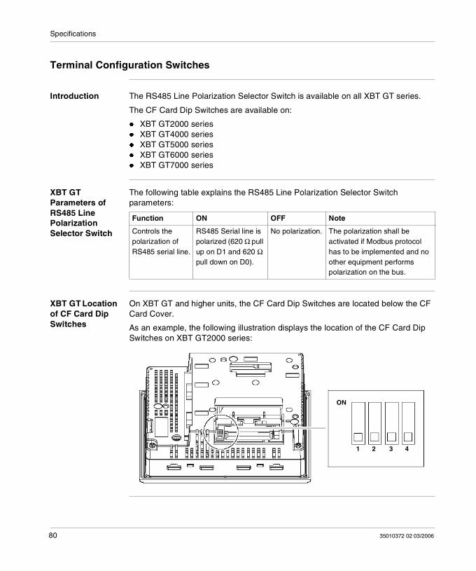
XBT GT Location of CF Card Dip Switches
On XBT GT and higher units, the CF Card Dip Switches are located below the CF Card Cover.
As an example, the following illustration displays the location of the CF Card Dip Switches on XBT GT2000 series:
Function ON OFF Note
Controls the polarization of RS485 serial line.
RS485 Serial line is polarized (620 Ω pull up on D1 and 620 Ω pull down on D0).
No polarization. The polarization shall be activated if Modbus protocol has to be implemented and no other equipment performs polarization on the bus.
ON
1 2 3 4
80 35010372 02 03/2006
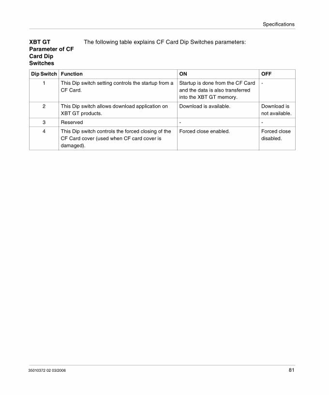
Specifications
XBT GT Parameter of CF Card Dip Switches
The following table explains CF Card Dip Switches parameters:
Dip Switch Function ON OFF
1 This Dip switch setting controls the startup from a CF Card.
Startup is done from the CF Card and the data is also transferred into the XBT GT memory.
-
2 This Dip switch allows download application on XBT GT products.
Download is available. Download is not available.
3 Reserved - -
4 This Dip switch controls the forced closing of the CF Card cover (used when CF card cover is damaged).
Forced close enabled. Forced close disabled.
35010372 02 03/2006 81
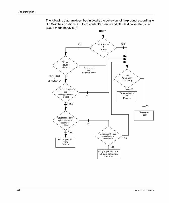
Specifications
The following diagram describes in details the behaviour of the product according to Dip Switches positions, CF Card content/absence and CF Card cover status, in BOOT mode behaviour:
BOOT
CF cardcoverStatus
CF card availableand
valid application onCF card
DIP Switch1
Status
Application on CF cardalready loaded to
memory once
ValidApplication on Memory
“Start from CF card”option selected at
applicationbuilding
Run applicationfrom
CF card
ON OFF
Run applicationfrom
Memory
Message touser
Copy application from CF card to Memory
and Boot
Cover openedand
Dip Switch 4 OFF
Cover closedor
DIP Switch 4 ON
NO
NO
YES
YES
NO
YES
NO
YES
82 35010372 02 03/2006
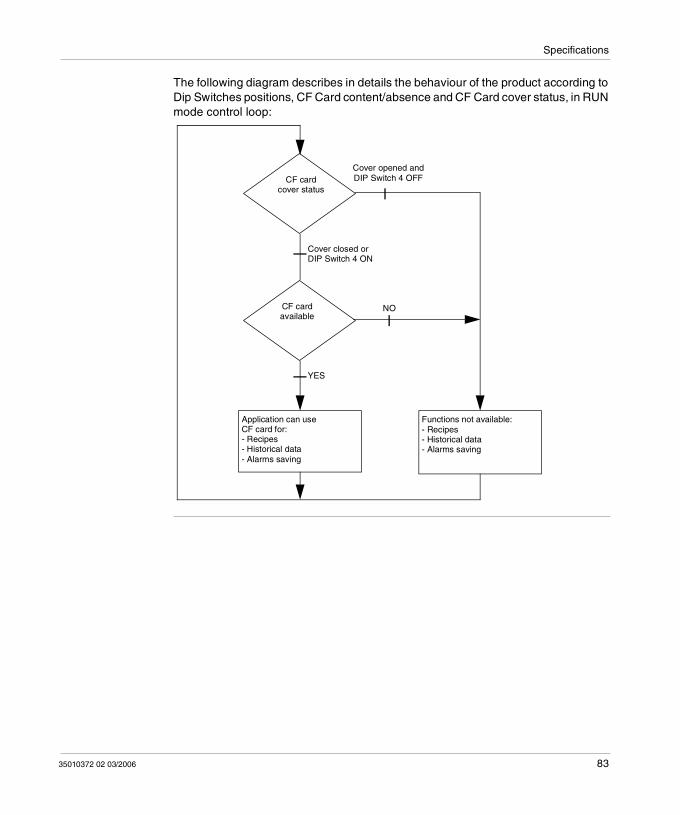
Specifications
The following diagram describes in details the behaviour of the product according to Dip Switches positions, CF Card content/absence and CF Card cover status, in RUN mode control loop:
CF cardavailable
CF cardcover status
Application can use CF card for:- Recipes- Historical data- Alarms saving
Functions not available:- Recipes- Historical data- Alarms saving
Cover closed orDIP Switch 4 ON
Cover opened and DIP Switch 4 OFF
NO
YES
35010372 02 03/2006 83
Specifications
3.5 Dimensions
At a Glance
Overview This section presents all the dimensions of XBT GT units.
What's in this Section?
This section contains the following topics:
Topic Page
XBT GT1000 Series Dimensions 85
XBT GT2000 Series Dimensions 88
XBT GT4000 Series Dimensions 92
XBT GT5000 Series Dimensions 96
XBT GT6000 Series Dimensions 104
XBT GT7000 Series Dimensions 108
Panel Cut Dimension 112
Installation Fasteners 114
84 35010372 02 03/2006
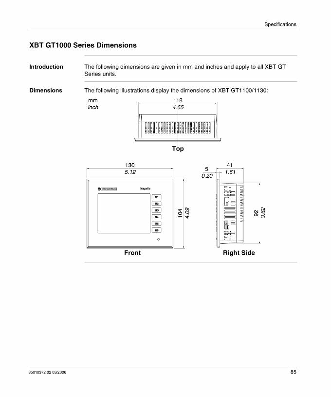
Specifications
XBT GT1000 Series Dimensions
Introduction The following dimensions are given in mm and inches and apply to all XBT GT Series units.
Dimensions The following illustrations display the dimensions of XBT GT1100/1130:
Front Right Side
Top
35010372 02 03/2006 85
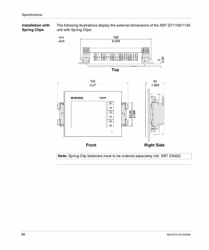
Specifications
Installation with Spring Clips
The following illustrations display the external dimensions of the XBT GT1100/1130 unit with Spring Clips:
Note: Spring Clip fasteners have to be ordered separately (ref. XBT Z3002)
Front Right Side
Top
86 35010372 02 03/2006
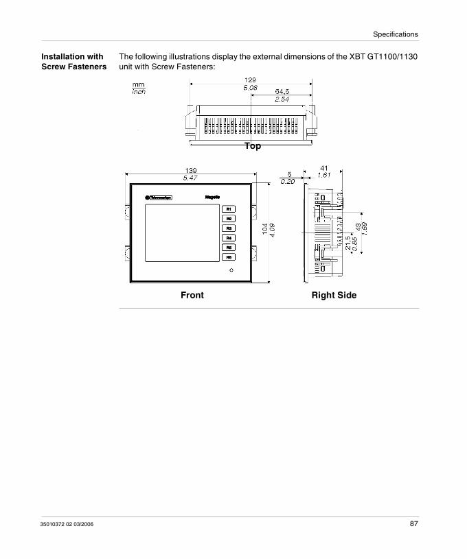
Specifications
Installation with Screw Fasteners
The following illustrations display the external dimensions of the XBT GT1100/1130 unit with Screw Fasteners:
Front Right Side
Top
35010372 02 03/2006 87
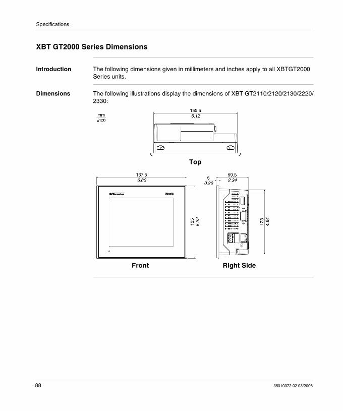
Specifications
XBT GT2000 Series Dimensions
Introduction The following dimensions given in millimeters and inches apply to all XBTGT2000 Series units.
Dimensions The following illustrations display the dimensions of XBT GT2110/2120/2130/2220/2330:
Top
Front Right Side
88 35010372 02 03/2006
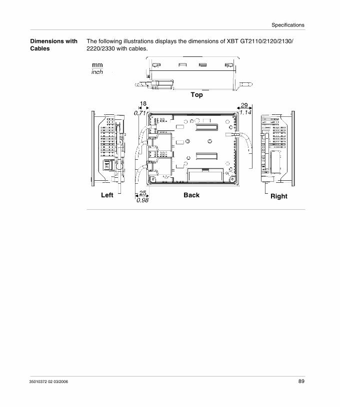
Specifications
Dimensions with Cables
The following illustrations displays the dimensions of XBT GT2110/2120/2130/2220/2330 with cables.
Top
BackLeft Right
35010372 02 03/2006 89
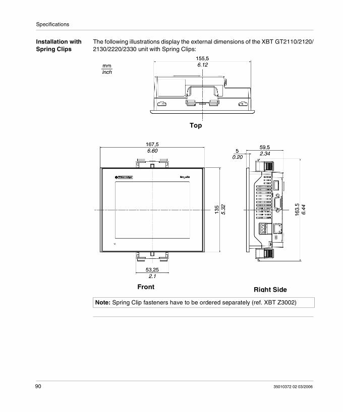
Specifications
Installation with Spring Clips
The following illustrations display the external dimensions of the XBT GT2110/2120/2130/2220/2330 unit with Spring Clips:
Note: Spring Clip fasteners have to be ordered separately (ref. XBT Z3002)
Top
Front Right Side
90 35010372 02 03/2006
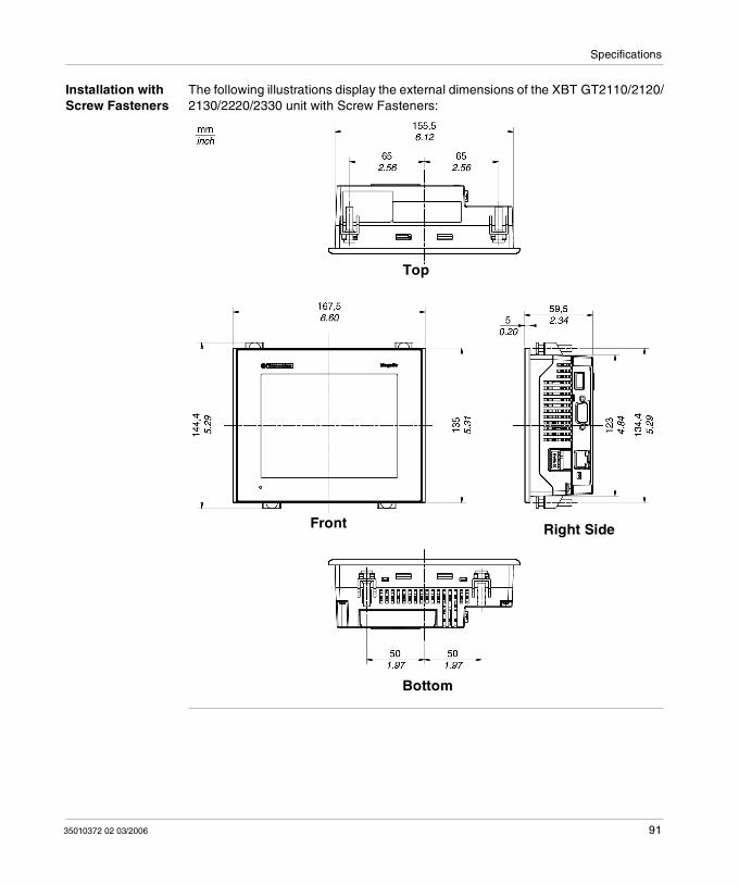
Specifications
Installation with Screw Fasteners
The following illustrations display the external dimensions of the XBT GT2110/2120/2130/2220/2330 unit with Screw Fasteners:
Top
Right Side
Bottom
Front
35010372 02 03/2006 91
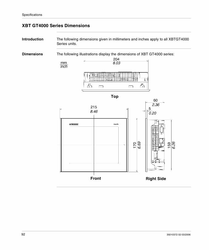
Specifications
XBT GT4000 Series Dimensions
Introduction The following dimensions given in millimeters and inches apply to all XBTGT4000 Series units.
Dimensions The following illustrations display the dimensions of XBT GT4000 series:
Top
Front Right Side
92 35010372 02 03/2006
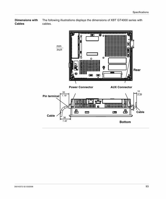
Specifications
Dimensions with Cables
The following illustrations displays the dimensions of XBT GT4000 series with cables.
30
AUX ConnectorPower Connector
Pin terminal
CableCable
Bottom
Rear
10
36
1.18
1.42
0.39
mminch
35010372 02 03/2006 93
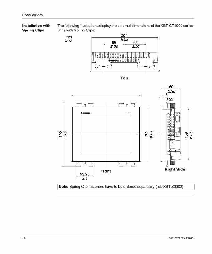
Specifications
Installation with Spring Clips
The following illustrations display the external dimensions of the XBT GT4000 series units with Spring Clips:
Note: Spring Clip fasteners have to be ordered separately (ref. XBT Z3002)
Top
Front Right Side
94 35010372 02 03/2006
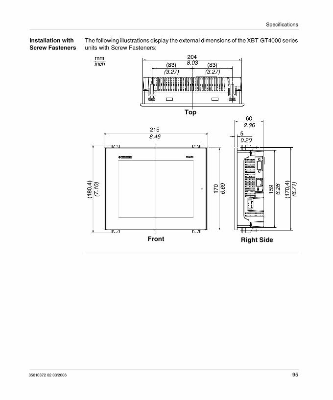
Specifications
Installation with Screw Fasteners
The following illustrations display the external dimensions of the XBT GT4000 series units with Screw Fasteners:
Top
Front Right Side
35010372 02 03/2006 95
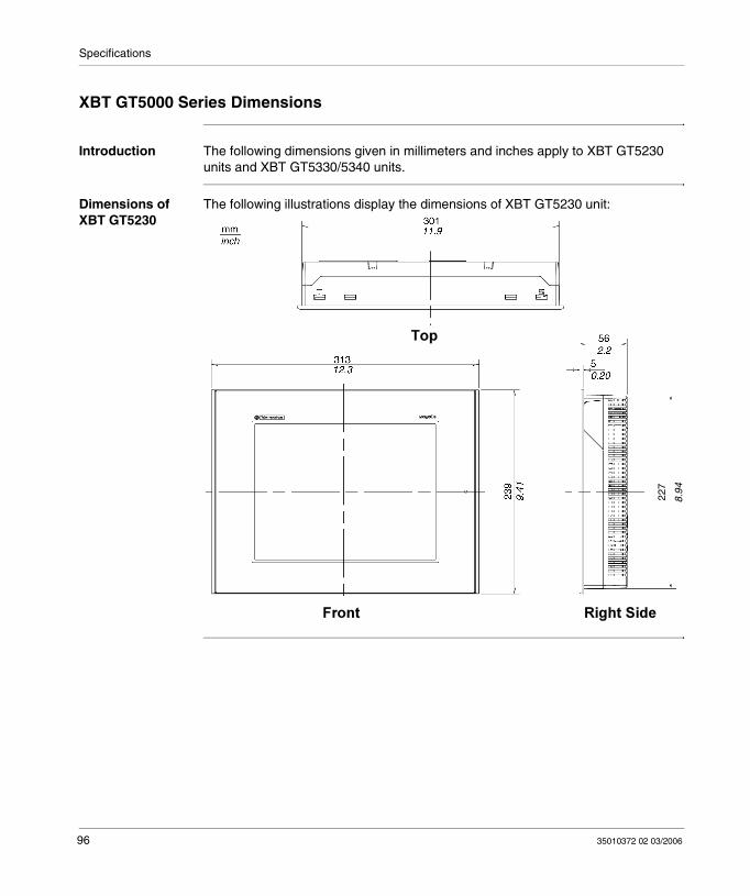
Specifications
XBT GT5000 Series Dimensions
Introduction The following dimensions given in millimeters and inches apply to XBT GT5230 units and XBT GT5330/5340 units.
Dimensions of XBT GT5230
The following illustrations display the dimensions of XBT GT5230 unit:
227
8.94
96 35010372 02 03/2006
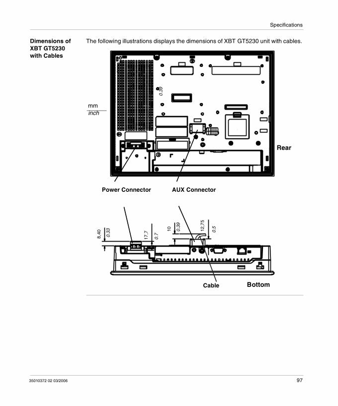
Specifications
Dimensions of XBT GT5230 with Cables
The following illustrations displays the dimensions of XBT GT5230 unit with cables.
10
Power Connector
Cable Bottom
Rear
AUX Connector
0.5
10
17,7
8,4
0
0.33 0.
39
12,7
5
mminch
0.7
0.39
35010372 02 03/2006 97
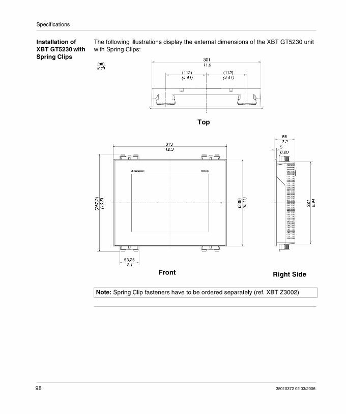
Specifications
Installation of XBT GT5230 with Spring Clips
The following illustrations display the external dimensions of the XBT GT5230 unit with Spring Clips:
Note: Spring Clip fasteners have to be ordered separately (ref. XBT Z3002)
Top
Front Right Side
98 35010372 02 03/2006
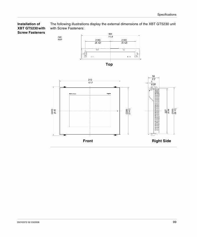
Specifications
Installation of XBT GT5230 with Screw Fasteners
The following illustrations display the external dimensions of the XBT GT5230 unit with Screw Fasteners:
Top
Front Right Side
35010372 02 03/2006 99
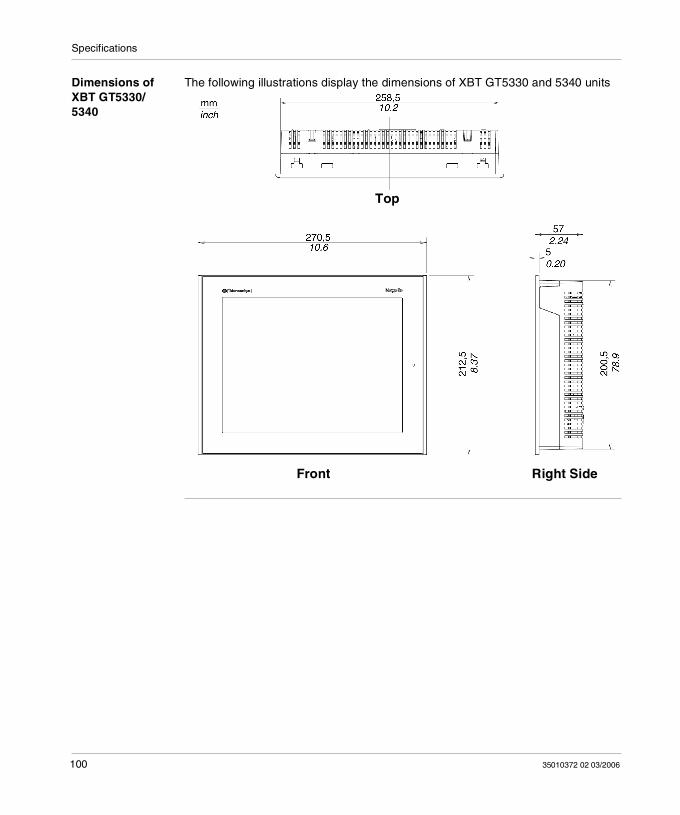
Specifications
Dimensions of XBT GT5330/5340
The following illustrations display the dimensions of XBT GT5330 and 5340 units
Top
Front Right Side
100 35010372 02 03/2006
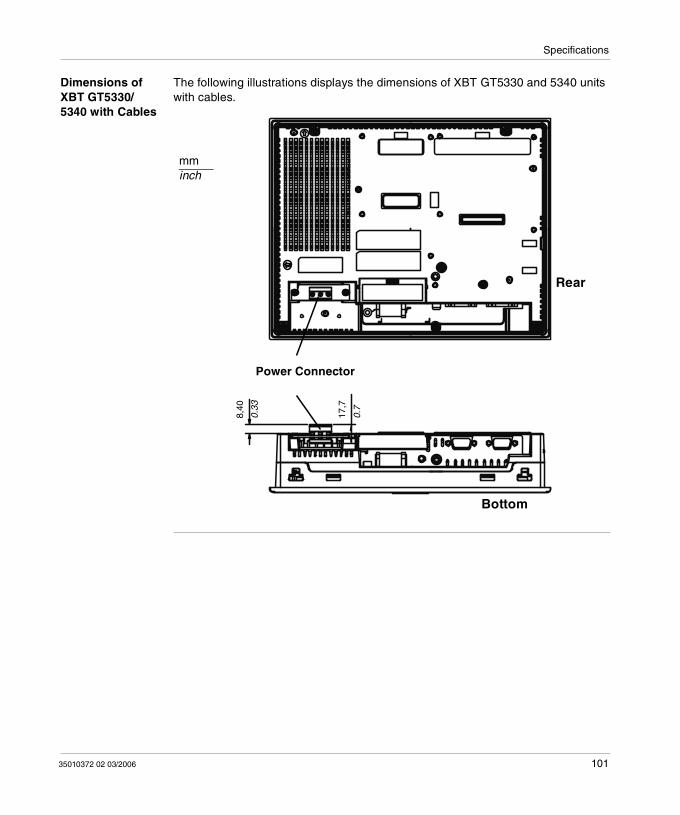
Specifications
Dimensions of XBT GT5330/5340 with Cables
The following illustrations displays the dimensions of XBT GT5330 and 5340 units with cables.
Power Connector
Bottom
Rear
8,40
0.33
17,7
0.7
mminch
35010372 02 03/2006 101
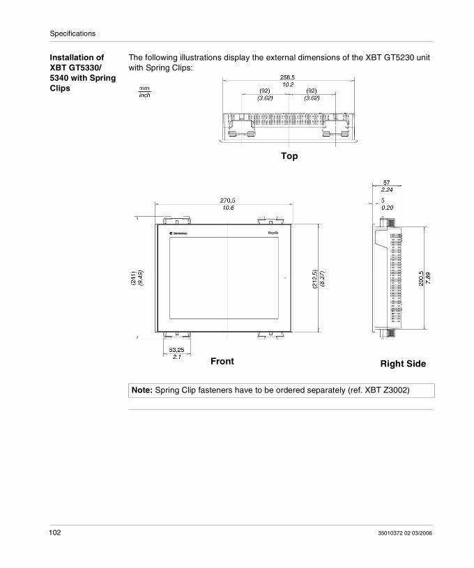
Specifications
Installation of XBT GT5330/5340 with Spring Clips
The following illustrations display the external dimensions of the XBT GT5230 unit with Spring Clips:
Note: Spring Clip fasteners have to be ordered separately (ref. XBT Z3002)
Top
Front Right Side
102 35010372 02 03/2006
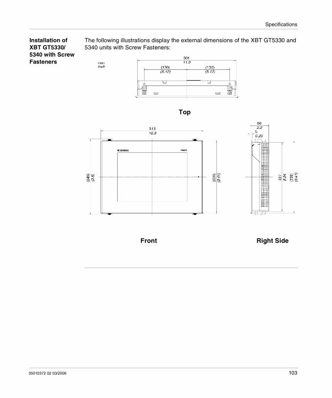
Specifications
Installation of XBT GT5330/5340 with Screw Fasteners
The following illustrations display the external dimensions of the XBT GT5330 and 5340 units with Screw Fasteners:
Top
Front Right Side
35010372 02 03/2006 103
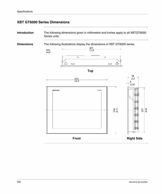
Specifications
XBT GT6000 Series Dimensions
Introduction The following dimensions given in millimeters and inches apply to all XBTGT6000 Series units.
Dimensions The following illustrations display the dimensions of XBT GT6000 series:
22
7
8.94
104 35010372 02 03/2006
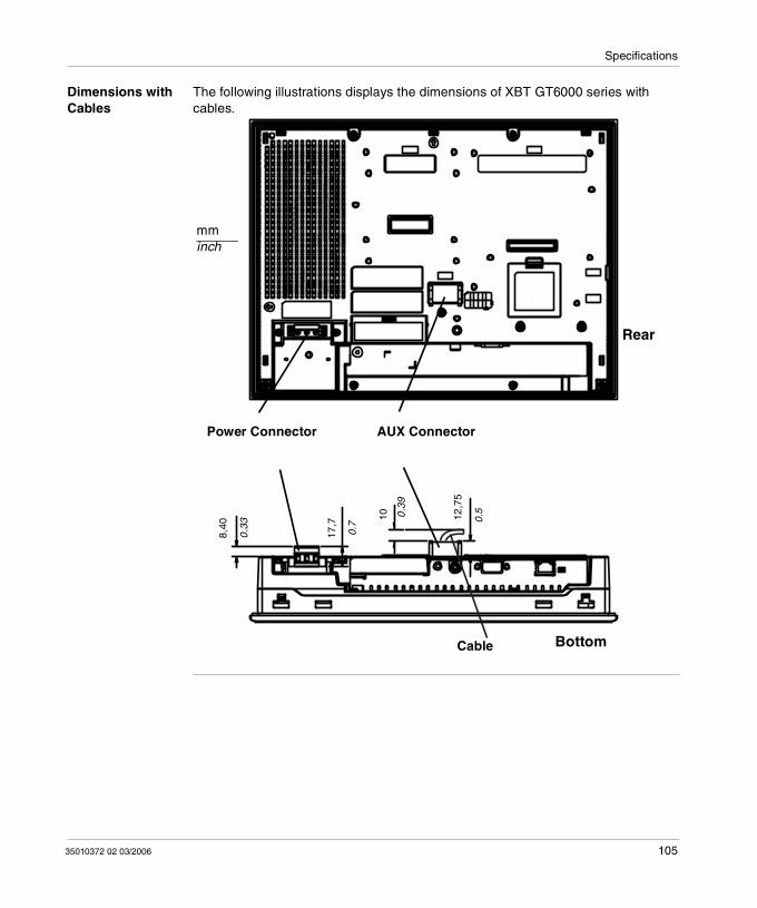
Specifications
Dimensions with Cables
The following illustrations displays the dimensions of XBT GT6000 series with cables.
Power Connector
Cable Bottom
Rear
0.5
10
17,7
8,40
AUX Connector
0.33 0.7
0.39
12,7
5
mminch
35010372 02 03/2006 105
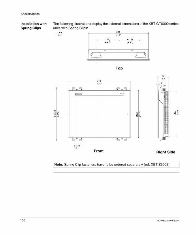
Specifications
Installation with Spring Clips
The following illustrations display the external dimensions of the XBT GT6000 series units with Spring Clips:
Note: Spring Clip fasteners have to be ordered separately (ref. XBT Z3002)
Top
Front Right Side
106 35010372 02 03/2006
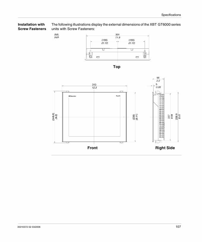
Specifications
Installation with Screw Fasteners
The following illustrations display the external dimensions of the XBT GT6000 series units with Screw Fasteners:
Top
Front Right Side
35010372 02 03/2006 107
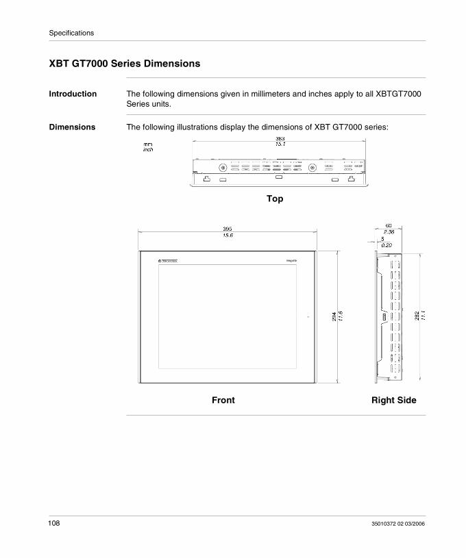
Specifications
XBT GT7000 Series Dimensions
Introduction The following dimensions given in millimeters and inches apply to all XBTGT7000 Series units.
Dimensions The following illustrations display the dimensions of XBT GT7000 series:
Top
Front Right Side
108 35010372 02 03/2006
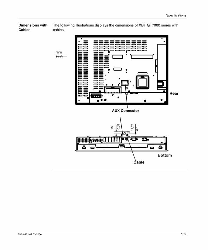
Specifications
Dimensions with Cables
The following illustrations displays the dimensions of XBT GT7000 series with cables.
AUX Connector
Bottom
Rear
Cable
mminch
0.510 0.39
12,7
5
35010372 02 03/2006 109
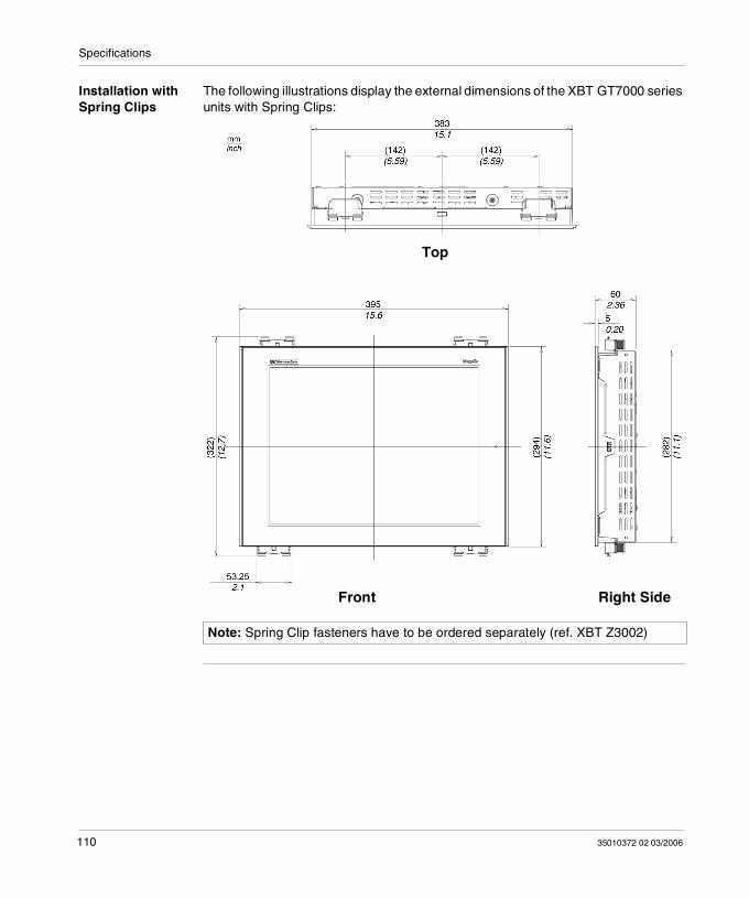
Specifications
Installation with Spring Clips
The following illustrations display the external dimensions of the XBT GT7000 series units with Spring Clips:
Note: Spring Clip fasteners have to be ordered separately (ref. XBT Z3002)
Top
Front Right Side
110 35010372 02 03/2006
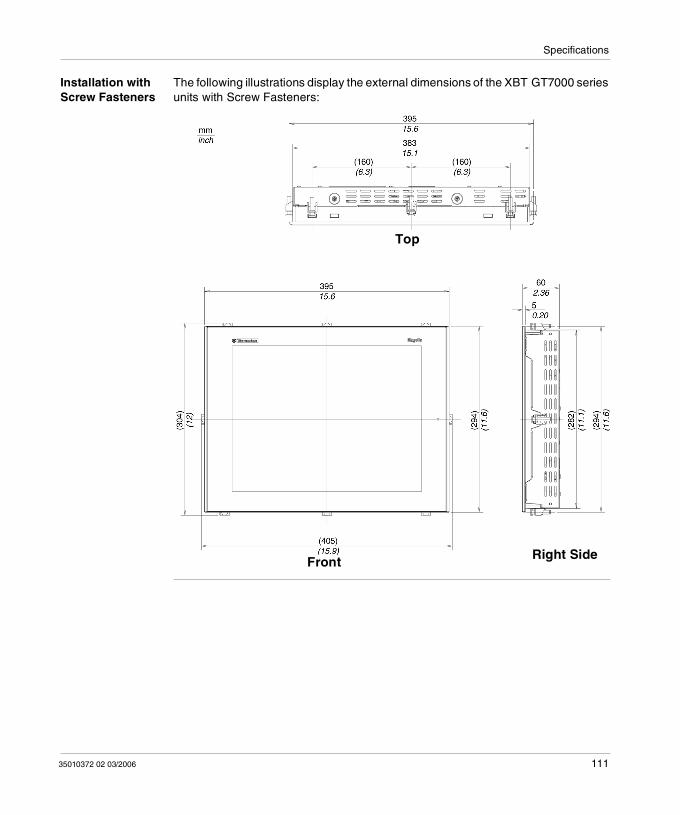
Specifications
Installation with Screw Fasteners
The following illustrations display the external dimensions of the XBT GT7000 series units with Screw Fasteners:
Top
Front Right Side
35010372 02 03/2006 111
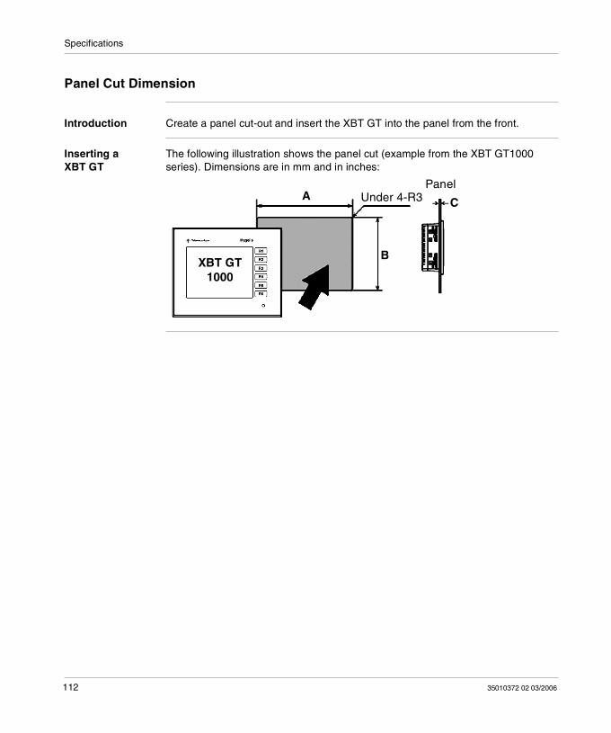
Specifications
Panel Cut Dimension
Introduction Create a panel cut-out and insert the XBT GT into the panel from the front.
Inserting a XBT GT
The following illustration shows the panel cut (example from the XBT GT1000 series). Dimensions are in mm and in inches:
Under 4-R3Panel
B
CA
XBT GT 1000
112 35010372 02 03/2006
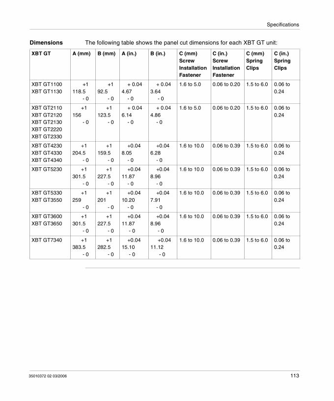
Specifications
Dimensions The following table shows the panel cut dimensions for each XBT GT unit:
XBT GT A (mm) B (mm) A (in.) B (in.) C (mm)Screw Installation Fastener
C (in.)Screw Installation Fastener
C (mm)Spring Clips
C (in.)Spring Clips
XBT GT1100XBT GT1130
+1118.5 - 0
+192.5 - 0
+ 0.044.67 - 0
+ 0.043.64 - 0
1.6 to 5.0 0.06 to 0.20 1.5 to 6.0 0.06 to 0.24
XBT GT2110XBT GT2120XBT GT2130XBT GT2220XBT GT2330
+1156 - 0
+1123.5 - 0
+ 0.046.14 - 0
+ 0.044.86 - 0
1.6 to 5.0 0.06 to 0.20 1.5 to 6.0 0.06 to 0.24
XBT GT4230XBT GT4330XBT GT4340
+1204.5 - 0
+1159.5 - 0
+0.048.05 - 0
+0.046.28 - 0
1.6 to 10.0 0.06 to 0.39 1.5 to 6.0 0.06 to 0.24
XBT GT5230 +1301.5 - 0
+1227.5 - 0
+0.0411.87 - 0
+0.048.96 - 0
1.6 to 10.0 0.06 to 0.39 1.5 to 6.0 0.06 to 0.24
XBT GT5330XBT GT3550
+1259 - 0
+1201 - 0
+0.0410.20 - 0
+0.047.91 - 0
1.6 to 10.0 0.06 to 0.39 1.5 to 6.0 0.06 to 0.24
XBT GT3600XBT GT3650
+1301.5 - 0
+1227.5 - 0
+0.0411.87 - 0
+0.048.96 - 0
1.6 to 10.0 0.06 to 0.39 1.5 to 6.0 0.06 to 0.24
XBT GT7340 +1383.5 - 0
+1282.5 - 0
+0.0415.10 - 0
+0.0411.12 - 0
1.6 to 10.0 0.06 to 0.39 1.5 to 6.0 0.06 to 0.24
35010372 02 03/2006 113
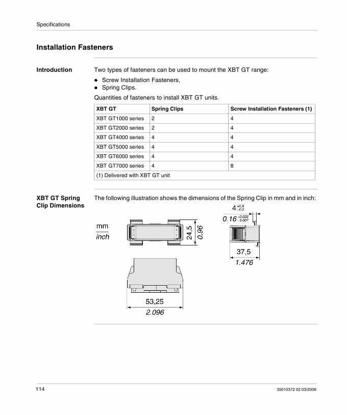
Specifications
Installation Fasteners
Introduction Two types of fasteners can be used to mount the XBT GT range:
Screw Installation Fasteners, Spring Clips.
Quantities of fasteners to install XBT GT units.
XBT GT Spring Clip Dimensions
The following illustration shows the dimensions of the Spring Clip in mm and in inch:
XBT GT Spring Clips Screw Installation Fasteners (1)
XBT GT1000 series 2 4
XBT GT2000 series 2 4
XBT GT4000 series 4 4
XBT GT5000 series 4 4
XBT GT6000 series 4 4
XBT GT7000 series 4 8
(1) Delivered with XBT GT unit
114 35010372 02 03/2006
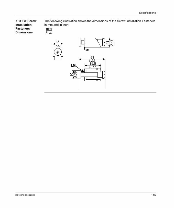
Specifications
XBT GT Screw Installation Fasteners Dimensions
The following illustration shows the dimensions of the Screw Installation Fasteners in mm and in inch:
35010372 02 03/2006 115
Specifications
116 35010372 02 03/2006
35010372 02 03/2006
4
Installation and WiringAt a glance
Overview This chapter describes the installation procedures and the wiring principles of XBT GT.
What's in this Chapter?
This chapter contains the following sections:
Section Topic Page
4.1 Installation 119
4.2 Wiring Precautions 126
4.3 Tool Port Connector 135
4.4 Ethernet Cable Connector 140
4.5 CF Card 143
4.6 USB Port 147
4.7 AUX Connector 158
117
Installation and Wiring
118 35010372 02 03/2006
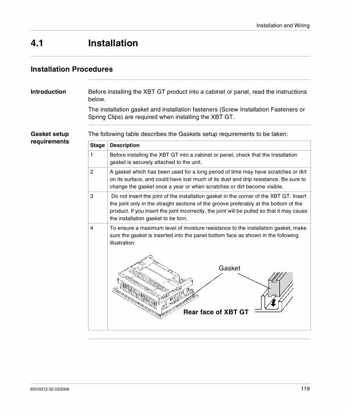
Installation and Wiring
4.1 Installation
Installation Procedures
Introduction Before installing the XBT GT product into a cabinet or panel, read the instructions below.
The installation gasket and installation fasteners (Screw Installation Fasteners or Spring Clips) are required when installing the XBT GT.
Gasket setup requirements
The following table describes the Gaskets setup requirements to be taken:
Stage Description
1 Before installing the XBT GT into a cabinet or panel, check that the Installation gasket is securely attached to the unit.
2 A gasket which has been used for a long period of time may have scratches or dirt on its surface, and could have lost much of its dust and drip resistance. Be sure to change the gasket once a year or when scratches or dirt become visible.
3 Do not insert the joint of the installation gasket in the corner of the XBT GT. Insert the joint only in the straight sections of the groove preferably at the bottom of the product. If you insert the joint incorrectly, the joint will be pulled so that it may cause the installation gasket to be torn.
4 To ensure a maximum level of moisture resistance to the installation gasket, make sure the gasket is inserted into the panel bottom face as shown in the following illustration:
Rear face of XBT GT
Gasket
35010372 02 03/2006 119
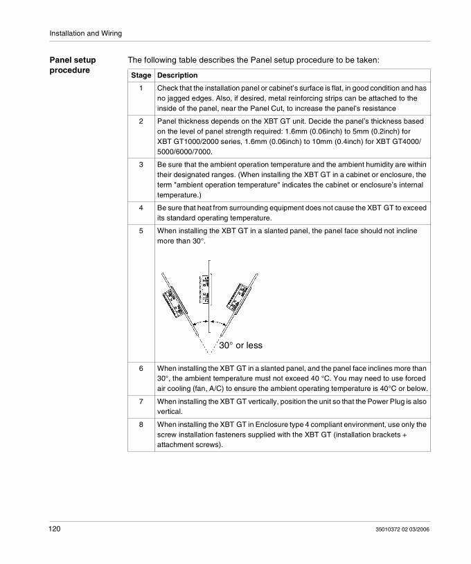
Installation and Wiring
Panel setup procedure
The following table describes the Panel setup procedure to be taken:
Stage Description
1 Check that the installation panel or cabinet’s surface is flat, in good condition and has no jagged edges. Also, if desired, metal reinforcing strips can be attached to the inside of the panel, near the Panel Cut, to increase the panel’s resistance
2 Panel thickness depends on the XBT GT unit. Decide the panel’s thickness based on the level of panel strength required: 1.6mm (0.06inch) to 5mm (0.2inch) for XBT GT1000/2000 series, 1.6mm (0.06inch) to 10mm (0.4inch) for XBT GT4000/5000/6000/7000.
3 Be sure that the ambient operation temperature and the ambient humidity are within their designated ranges. (When installing the XBT GT in a cabinet or enclosure, the term "ambient operation temperature" indicates the cabinet or enclosure’s internal temperature.)
4 Be sure that heat from surrounding equipment does not cause the XBT GT to exceed its standard operating temperature.
5 When installing the XBT GT in a slanted panel, the panel face should not incline more than 30°.
6 When installing the XBT GT in a slanted panel, and the panel face inclines more than 30°, the ambient temperature must not exceed 40 °C. You may need to use forced air cooling (fan, A/C) to ensure the ambient operating temperature is 40°C or below.
7 When installing the XBT GT vertically, position the unit so that the Power Plug is also vertical.
8 When installing the XBT GT in Enclosure type 4 compliant environment, use only the screw installation fasteners supplied with the XBT GT (installation brackets + attachment screws).
30° or less
120 35010372 02 03/2006
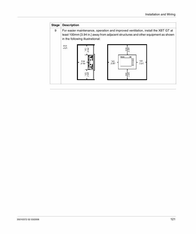
Installation and Wiring
9 For easier maintenance, operation and improved ventilation, install the XBT GT at least 100mm [3.94 in.] away from adjacent structures and other equipment as shown in the following illustrational:
Stage Description
35010372 02 03/2006 121
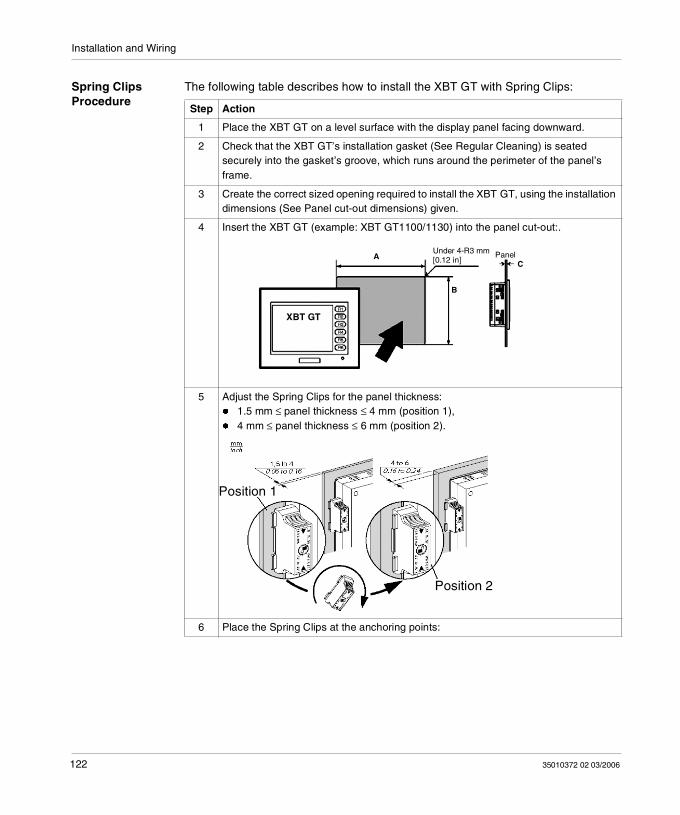
Installation and Wiring
Spring Clips Procedure
The following table describes how to install the XBT GT with Spring Clips:
Step Action
1 Place the XBT GT on a level surface with the display panel facing downward.
2 Check that the XBT GT’s installation gasket (See Regular Cleaning) is seated securely into the gasket’s groove, which runs around the perimeter of the panel’s frame.
3 Create the correct sized opening required to install the XBT GT, using the installation dimensions (See Panel cut-out dimensions) given.
4 Insert the XBT GT (example: XBT GT1100/1130) into the panel cut-out:.
5 Adjust the Spring Clips for the panel thickness: 1.5 mm ≤ panel thickness ≤ 4 mm (position 1), 4 mm ≤ panel thickness ≤ 6 mm (position 2).
6 Place the Spring Clips at the anchoring points:
B
A PanelC
XBT GT
Under 4-R3 mm[0.12 in]
Position 1
Position 2
122 35010372 02 03/2006
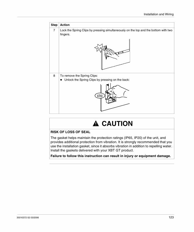
Installation and Wiring
7 Lock the Spring Clips by pressing simultaneously on the top and the bottom with two fingers.
8 To remove the Spring Clips: Unlock the Spring Clips by pressing on the back:
CAUTIONRISK OF LOSS OF SEAL
The gasket helps maintain the protection ratings (IP65, IP20) of the unit, and provides additional protection from vibration. It is strongly recommended that you use the installation gasket, since it absorbs vibration in addition to repelling water. Install the gaskets delivered with your XBT GT product.
Failure to follow this instruction can result in injury or equipment damage.
Step Action
35010372 02 03/2006 123
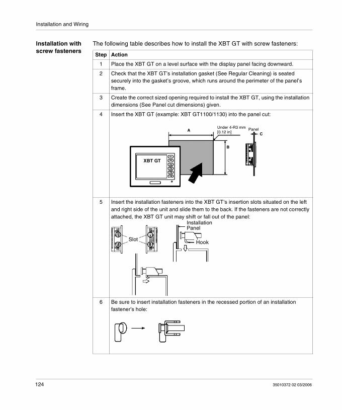
Installation and Wiring
Installation with screw fasteners
The following table describes how to install the XBT GT with screw fasteners:
Step Action
1 Place the XBT GT on a level surface with the display panel facing downward.
2 Check that the XBT GT’s installation gasket (See Regular Cleaning) is seated securely into the gasket’s groove, which runs around the perimeter of the panel’s frame.
3 Create the correct sized opening required to install the XBT GT, using the installation dimensions (See Panel cut dimensions) given.
4 Insert the XBT GT (example: XBT GT1100/1130) into the panel cut:
5 Insert the installation fasteners into the XBT GT‘s insertion slots situated on the left and right side of the unit and slide them to the back. If the fasteners are not correctly attached, the XBT GT unit may shift or fall out of the panel:
6 Be sure to insert installation fasteners in the recessed portion of an installation fastener’s hole:
B
A PanelC
XBT GT
Under 4-R3 mm[0.12 in]
InstallationPanel
HookSlot
124 35010372 02 03/2006
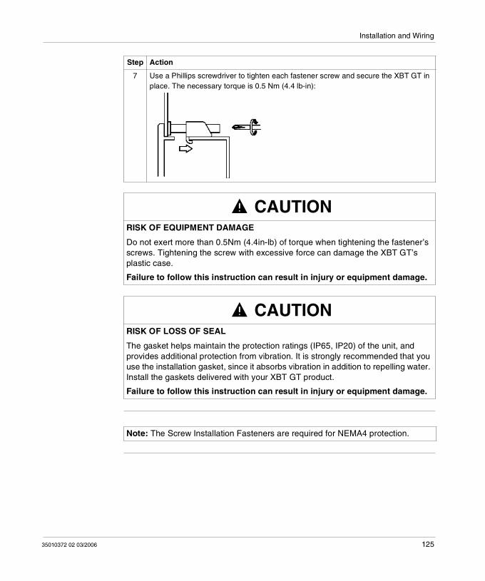
Installation and Wiring
7 Use a Phillips screwdriver to tighten each fastener screw and secure the XBT GT in place. The necessary torque is 0.5 Nm (4.4 lb-in):
CAUTIONRISK OF EQUIPMENT DAMAGE
Do not exert more than 0.5Nm (4.4in-lb) of torque when tightening the fastener’s screws. Tightening the screw with excessive force can damage the XBT GT’s plastic case.
Failure to follow this instruction can result in injury or equipment damage.
CAUTIONRISK OF LOSS OF SEAL
The gasket helps maintain the protection ratings (IP65, IP20) of the unit, and provides additional protection from vibration. It is strongly recommended that you use the installation gasket, since it absorbs vibration in addition to repelling water. Install the gaskets delivered with your XBT GT product.
Failure to follow this instruction can result in injury or equipment damage.
Step Action
Note: The Screw Installation Fasteners are required for NEMA4 protection.
35010372 02 03/2006 125
Installation and Wiring
4.2 Wiring Precautions
At a glance
Overview This section presents principle of XBT GT wiring.
What's in this Section?
This section contains the following topics:
Topic Page
Connecting the Power Cord 127
Connecting the Power Supply 130
Grounding 132
Input/Output Line placement 134
126 35010372 02 03/2006
Installation and Wiring
Connecting the Power Cord
Introduction Follow these instructions when supplying power to the XBT GT unit.
Note: When the Frame Ground terminal is connected, be sure the wire is grounded.
Not grounding the XBT GT unit will result in excessive noise and vibration. Grounding is required to assure EMC level immunity.
The Shield Ground (SG) and Frame Ground (FG) terminals are connected internally in the XBT GT unit.
If your system is installed with the 24 VDC power connected to the Frame Ground (typical in systems such as fire protection), when connecting other devices, be sure the design of the overall system does not produce a short loop.
WARNINGRISK OF ELECTRIC SHOCK
Be sure the 24V DC power OFF when wiring to the power terminals of the XBT GT unit.
The XBT GT unit uses only 24V DC power. Using any other level of power can damage both the power supply and the XBT GT unit.
Since the XBT GT is not equipped with a power switch, be sure to connect a power switch to the XBT GT’s power supply.
Be sure to ground the XBT GT's FG terminal. Failure to do so can lead to an electrical shock or XBT GT malfunction.
Failure to follow this instruction can result in death, serious injury, or equipment damage.
35010372 02 03/2006 127
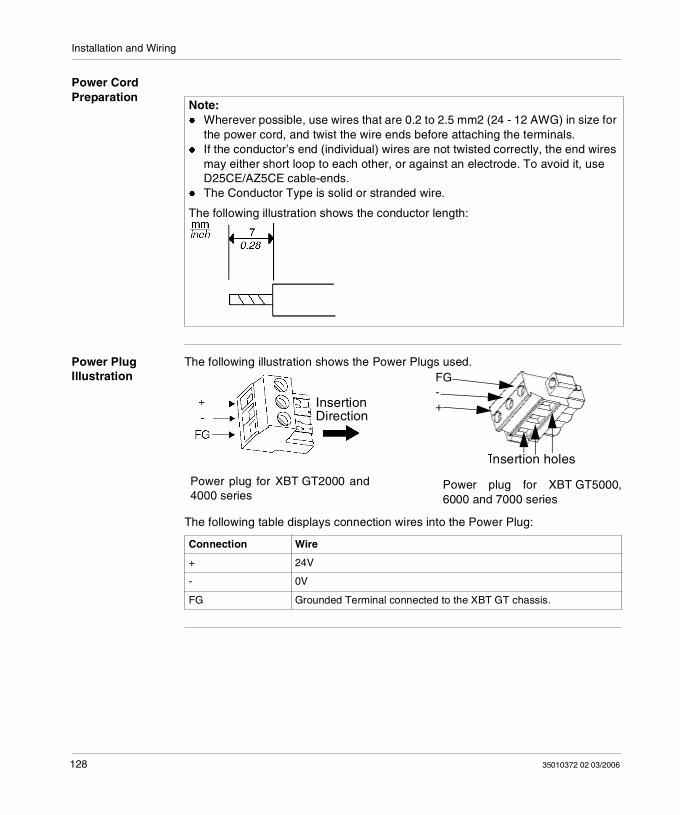
Installation and Wiring
Power Cord Preparation
Power Plug Illustration
The following illustration shows the Power Plugs used.
The following table displays connection wires into the Power Plug:
Note: Wherever possible, use wires that are 0.2 to 2.5 mm2 (24 - 12 AWG) in size for
the power cord, and twist the wire ends before attaching the terminals. If the conductor’s end (individual) wires are not twisted correctly, the end wires
may either short loop to each other, or against an electrode. To avoid it, use D25CE/AZ5CE cable-ends.
The Conductor Type is solid or stranded wire.
The following illustration shows the conductor length:
Connection Wire
+ 24V
- 0V
FG Grounded Terminal connected to the XBT GT chassis.
InsertionDirection
FG-+
Insertion holes
Power plug for XBT GT2000 and4000 series
Power plug for XBT GT5000,6000 and 7000 series
128 35010372 02 03/2006
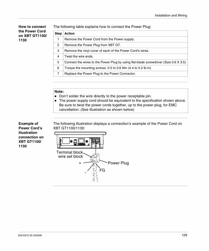
Installation and Wiring
How to connect the Power Cord on XBT GT1100/1130
The following table explains how to connect the Power Plug:
Example of Power Cord’s illustration connection on XBT GT1100/1130
The following illustration displays a connection’s example of the Power Cord on XBT GT1100/1130:
Step Action
1 Remove the Power Cord from the Power supply.
2 Remove the Power Plug from XBT GT.
3 Remove the vinyl cover of each of the Power Cord’s wires.
4 Twist the wire ends.
5 Connect the wires to the Power Plug by using flat-blade screwdriver (Size 0.6 X 3.5)
6 Torque the mounting screws: 0.5 to 0.6 Nm (4.4 to 5.2 lb-in)
7 Replace the Power Plug to the Power Connector.
Note: Don’t solder the wire directly to the power receptable pin. The power supply cord should be equivalent to the specification shown above.
Be sure to twist the power cords together, up to the power plug, for EMC cancellation. (See illustration as shown below)
Power Plug
FG
Terminal blockwire set block
35010372 02 03/2006 129
Installation and Wiring
Connecting the Power Supply
Introduction Follow these instructions when supplying power to the XBT GT unit.
Precautions Connect the power cord to the Power Connector on the side of the XBT GT unit using the Power Plug.
Between the line and the ground, be sure to use a regulated power supply with a Class 2 Power Supply
To increase the noise resistance, be sure to twist the ends of the power cord wires before connecting them to the Power Plug.
The XBT GT unit’s power supply cord should not be bundled with or kept close to main circuit lines (high voltage, high current), or input/output signal lines.
Connect a lightning surge absorber to handle power surges. To reduce noise, make the power cord as short as possible.
WARNINGRISK OF EQUIPMENT DAMAGE AND POWER LOSS
Avoid excessive stress on the power cable to prevent accidental disconnection. Securely attach power cables to the panel or cabinet. Use the designated torque to tighten the unit’s terminal block screws. Install and fasten unit on installation panel or cabinet prior to connecting Power
Supply and Communication lines.
Excessive stress on the power connection or attempting to install a unit with the power cables connected may disconnect or cause damage to the power connections, which can cause short circuits, fire or unintended equipment operation.
Failure to follow this instruction can result in death, serious injury, or equipment damage.
130 35010372 02 03/2006
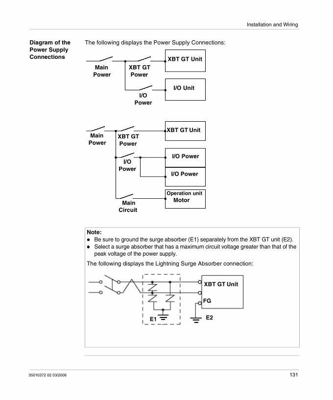
Installation and Wiring
Diagram of the Power Supply Connections
The following displays the Power Supply Connections:
Note: Be sure to ground the surge absorber (E1) separately from the XBT GT unit (E2). Select a surge absorber that has a maximum circuit voltage greater than that of the
peak voltage of the power supply.
The following displays the Lightning Surge Absorber connection:
XBT GT Unit
I/O Unit
XBT GT Unit
I/O Power
I/O Power
Operation unit Motor
Main Power
XBT GT Power
I/O Power
Main Power
XBT GT Power
I/OPower
Main Circuit
XBT GT Unit
FG
E2 E1
35010372 02 03/2006 131
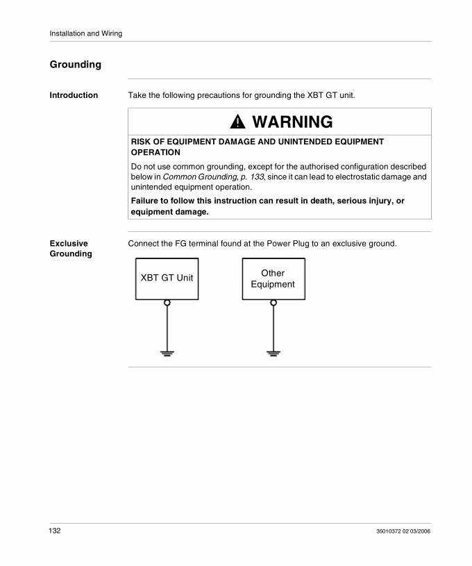
Installation and Wiring
Grounding
Introduction Take the following precautions for grounding the XBT GT unit.
Exclusive Grounding
Connect the FG terminal found at the Power Plug to an exclusive ground.
WARNINGRISK OF EQUIPMENT DAMAGE AND UNINTENDED EQUIPMENT OPERATION
Do not use common grounding, except for the authorised configuration described below in Common Grounding, p. 133, since it can lead to electrostatic damage and unintended equipment operation.
Failure to follow this instruction can result in death, serious injury, or equipment damage.
XBT GT Unit OtherEquipment
132 35010372 02 03/2006
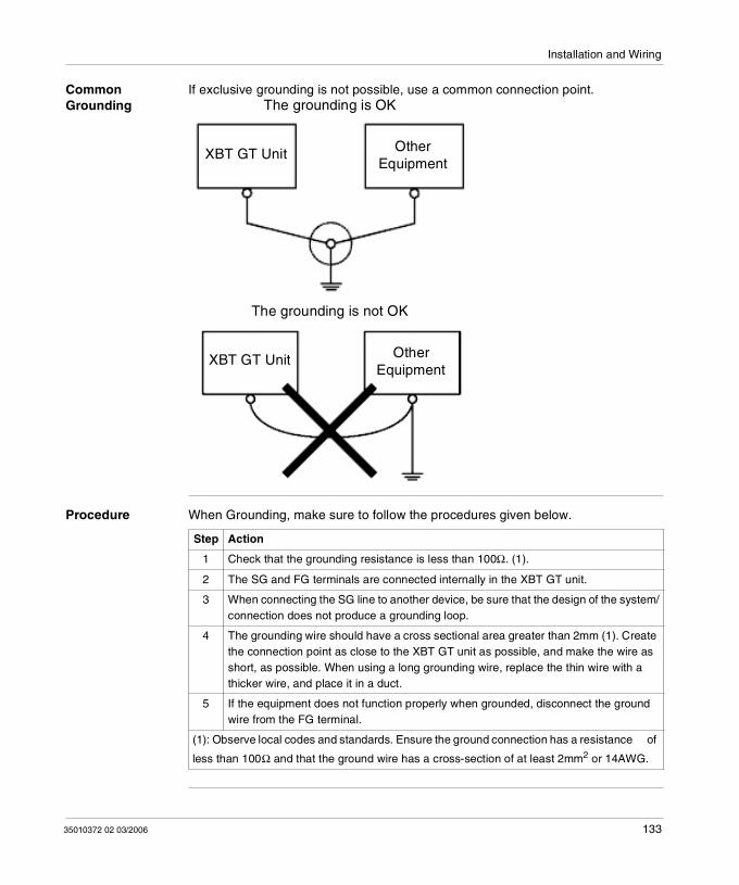
Installation and Wiring
Common Grounding
If exclusive grounding is not possible, use a common connection point.
Procedure When Grounding, make sure to follow the procedures given below.
XBT GT Unit OtherEquipment
The grounding is OK
XBT GT Unit OtherEquipment
The grounding is not OK
Step Action
1 Check that the grounding resistance is less than 100Ω. (1).
2 The SG and FG terminals are connected internally in the XBT GT unit.
3 When connecting the SG line to another device, be sure that the design of the system/connection does not produce a grounding loop.
4 The grounding wire should have a cross sectional area greater than 2mm (1). Create the connection point as close to the XBT GT unit as possible, and make the wire as short, as possible. When using a long grounding wire, replace the thin wire with a thicker wire, and place it in a duct.
5 If the equipment does not function properly when grounded, disconnect the ground wire from the FG terminal.
(1): Observe local codes and standards. Ensure the ground connection has a resistance of
less than 100Ω and that the ground wire has a cross-section of at least 2mm2 or 14AWG.
35010372 02 03/2006 133
Installation and Wiring
Input/Output Line placement
Introduction Input and output signal lines must be separated from the power supply cables for operating circuits.
If this is not possible, use a shielded cable and connect the shield to the XBT GT’s FG terminal.
134 35010372 02 03/2006
Installation and Wiring
4.3 Tool Port Connector
At a Glance
Overview This section describes the Tool Port Connector Installation.
What's in this Section?
This section contains the following topics:
Topic Page
Presentation 136
USB Data Transfer Cable (XBT ZG925) - USB Driver Installation 137
35010372 02 03/2006 135
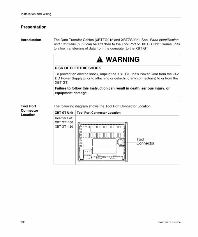
Installation and Wiring
Presentation
Introduction The Data Transfer Cables (XBTZG915 and XBTZG925). See. Parts Identification and Functions, p. 58 can be attached to the Tool Port on XBT GT11** Series units to allow transferring of data from the computer to the XBT GT
Tool Port Connector Location
The following diagram shows the Tool Port Connector Location.
WARNINGRISK OF ELECTRIC SHOCK
To prevent an electric shock, unplug the XBT GT unit’s Power Cord from the 24V DC Power Supply prior to attaching or detaching any connector(s) to or from the XBT GT.
Failure to follow this instruction can result in death, serious injury, or equipment damage.
XBT GT Unit Tool Port Connector Location
Rear face of: XBT GT1100 XBT GT1130
ToolConnector
136 35010372 02 03/2006
Installation and Wiring
USB Data Transfer Cable (XBT ZG925) - USB Driver Installation
Introduction The USB Data Transfer Cable is used to download data from a PC running Vijeo-Designer to the XBT GT unit. It connects to the Tool Port of the XBT GT.
Installation Requirements
The PC must run on Microsoft Windows 2000 or Windows XP.
You will need the installation CD for Vijeo-Designer.
CAUTIONRISK OF EQUIPMENT DAMAGE
Follow the procedure described below to prevent damage to the cable connector or the XBT GT. When connecting the USB Data Transfer Cable to the PC or to the XBT GT unit,
insert the cable’s connector at the correct 90° angle.
When disconnecting the cable, make sure to hold the connector, not the cable itself.
If the cable is unplugged from the port designated during installation and connected to a different port, the Operating System (OS) will not recognize the new port. Therefore, make sure to always use the port designated during installation.
If the installation does not complete successfully, restart the PC and quit all resident applications before re-installing the software.
Failure to follow this instruction can result in injury or equipment damage.
35010372 02 03/2006 137
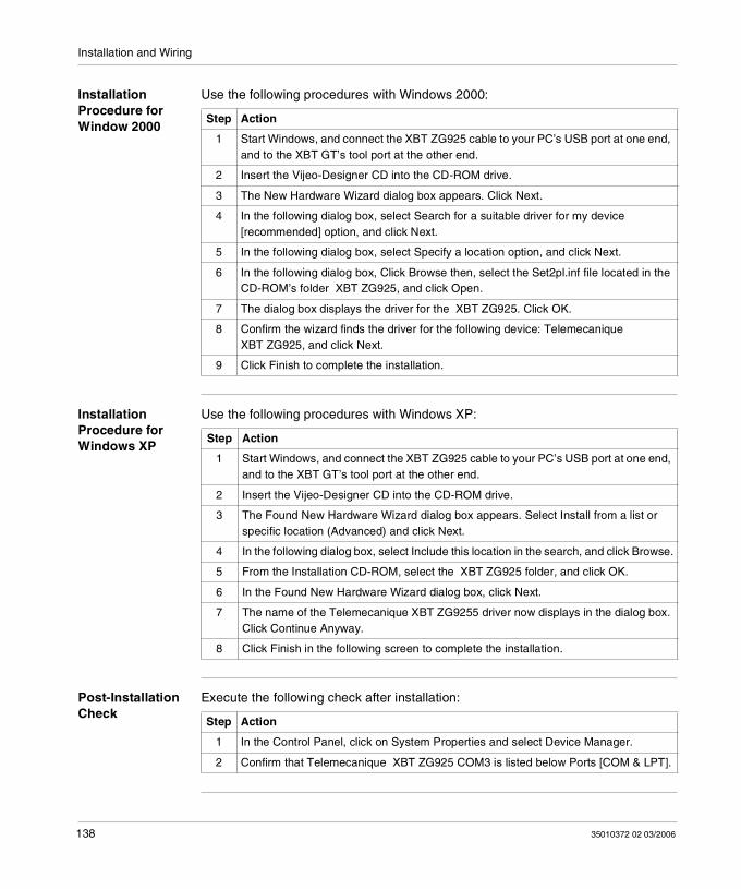
Installation and Wiring
Installation Procedure for Window 2000
Use the following procedures with Windows 2000:
Installation Procedure for Windows XP
Use the following procedures with Windows XP:
Post-Installation Check
Execute the following check after installation:
Step Action
1 Start Windows, and connect the XBT ZG925 cable to your PC’s USB port at one end, and to the XBT GT’s tool port at the other end.
2 Insert the Vijeo-Designer CD into the CD-ROM drive.
3 The New Hardware Wizard dialog box appears. Click Next.
4 In the following dialog box, select Search for a suitable driver for my device [recommended] option, and click Next.
5 In the following dialog box, select Specify a location option, and click Next.
6 In the following dialog box, Click Browse then, select the Set2pl.inf file located in the CD-ROM’s folder XBT ZG925, and click Open.
7 The dialog box displays the driver for the XBT ZG925. Click OK.
8 Confirm the wizard finds the driver for the following device: Telemecanique XBT ZG925, and click Next.
9 Click Finish to complete the installation.
Step Action
1 Start Windows, and connect the XBT ZG925 cable to your PC’s USB port at one end, and to the XBT GT’s tool port at the other end.
2 Insert the Vijeo-Designer CD into the CD-ROM drive.
3 The Found New Hardware Wizard dialog box appears. Select Install from a list or specific location (Advanced) and click Next.
4 In the following dialog box, select Include this location in the search, and click Browse.
5 From the Installation CD-ROM, select the XBT ZG925 folder, and click OK.
6 In the Found New Hardware Wizard dialog box, click Next.
7 The name of the Telemecanique XBT ZG9255 driver now displays in the dialog box. Click Continue Anyway.
8 Click Finish in the following screen to complete the installation.
Step Action
1 In the Control Panel, click on System Properties and select Device Manager.
2 Confirm that Telemecanique XBT ZG925 COM3 is listed below Ports [COM & LPT].
138 35010372 02 03/2006
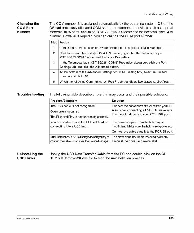
Installation and Wiring
Changing the COM Port Number
The COM number 3 is assigned automatically by the operating system (OS). If the OS had previously allocated COM 3 or other numbers for devices such as Internal modems, IrDA ports, and so on, XBT ZG9255 is allocated to the next available COM number. However if required, you can change the COM port number.
Troubleshooting The following table describe errors that may occur and their possible solutions:
Uninstalling the USB Driver
Unplug the USB Data Transfer Cable from the PC and double-click on the CD-ROM’s DRemover2K.exe file to start the uninstallation process.
Step Action
1 In the Control Panel, click on System Properties and select Device Manager.
2 Click to expand the Ports [COM & LPT] folder, right-click the Telemecanique XBT ZG925 COM 3 node, and then click Properties.
3 In the Telemecanique XBT ZG925 [COM3] Properties dialog box, click the Port Settings tab, and click the Advanced button.
4 At the bottom of the Advanced Settings for COM 3 dialog box, select an unused number and click OK.
5 When the following Communication Port Properties dialog box appears, click Yes.
Problem/Symptom Solution
The USB cable is not recognized. Connect the cable correctly, or restart you PC. Also, when connecting a USB hub, make sure to connect it directly to your PC’s USB port.
Overcurrent occurred
The Plug and Play is not functioning correctly.
You are unable to use the USB cable after connecting it to a USB hub.
The power supplied from the hub may be insufficient. Make sure the hub is self-powered.
Connect the cable directly to the PC USB port.
After installation, a "?" is displayed when you try to confirm the cable’s status via the Device Manager.
The driver has not been installed correctly. Unionist the driver and re-install it.
35010372 02 03/2006 139

Installation and Wiring
4.4 Ethernet Cable Connector
Presentation
Introduction The XBT GT unit (except for the XBT GT2110/2120/2220 models) comes equipped with an IEEE802.3 compliant Ethernet Interface, that transmits data at 10Mbps or 100 Mbps.
140 35010372 02 03/2006
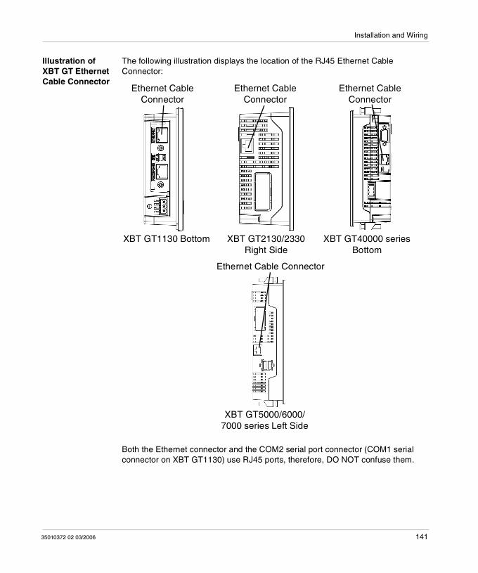
Installation and Wiring
Illustration of XBT GT Ethernet Cable Connector
The following illustration displays the location of the RJ45 Ethernet Cable Connector:
Both the Ethernet connector and the COM2 serial port connector (COM1 serial connector on XBT GT1130) use RJ45 ports, therefore, DO NOT confuse them.
XBT GT1130 Bottom
Ethernet CableConnector
Ethernet CableConnector
XBT GT2130/2330 Right Side
Ethernet Cable Connector
Ethernet Cable Connector
XBT GT5000/6000/7000 series Left Side
XBT GT40000 series Bottom
35010372 02 03/2006 141
Installation and Wiring
WARNINGRISK OF MATERIAL DAMAGE AND UNINTENDED EQUIPMENT OPERATION
Do not connect the serial cable to the Ethernet port. Do not connect the Ethernet cable to the serial port. Carefully observe the product markings distinguishing between the Ethernet
and serial ports.
Since Ethernet Port and the serial port (RJ45) share the same type of plug, there is a risk of swapping the Ethernet line with the serial line. Improper connections may result in damage to the XBT GT or to remotely connected equipment, and may cause unintended equipment operation.
Failure to follow this instruction can result in death, serious injury, or equipment damage.
Note: It is recommended that your Ethernet network is installed by a trained and qualified person.You may be able to use the 1:1 connection with a cross cable depending on the connected PCs and network cards. Make sure to use 1:1 connections with a hub or a switch.
142 35010372 02 03/2006
Installation and Wiring
4.5 CF Card
CF Card Installation and Removal
Introduction The following XBT GT target machines support the use of CF cards.
XBT GT2000 series (except for XBT GT2110) XBT GT4000 series XBT GT5000 series XBT GT6000 series XBT GT7000 series
35010372 02 03/2006 143
Installation and Wiring
Precautions When using the XBT GT Unit and a CF Card, follow the precautions below:
Prior to inserting or removing a CF Card, be sure to turn the XBT GT unit’s CF Card ACCESS switch OFF and to confirm that the ACCESS lamp is not lit. If you do not, CF Card internal data may be damaged or lost.
Check that the CF Card DIP Switches setting are appropriate. While a CF Card is being accessed, NEVER turn OFF or reset the XBT GT, or
insert or remove the CF Card. Prior to performing these operations, create and use a special XBT GT application screen that will prevent access to the CF Card.
Prior to inserting a CF Card, familiarize yourself with the CF Card’s front and rear face orientation, as well as the CF Card connector’s position. If the CF Card is not correctly positioned when it is inserted into the Mulit Unit, the CF Card’s internal data and the XBT GT unit may be damaged or broken.
Be sure to use only CF Cards manufactured by Schneider Electric. XBT GT unit performance cannot be guaranteed when using another manufacturer’s CF Card.
Once XBT GT data is lost, it cannot be recovered. Since accidental data loss can occur at any time, be sure to back up all XBT GT screen and CF Card data regularly.
CAUTIONRISK OF EQUIPMENT DAMAGE
Be sure to follow the instructions given below to prevent the CF Card’s internal data from being destroyed or a CF Card malfunction from occurring: DO NOT bend the CF Card. DO NOT drop or strike the CF Card against another object. Keep the CF Card dry. DO NOT touch the CF Card connectors. DO NOT disassemble or modify the CF Card.
Failure to follow this instruction can result in injury or equipment damage.
144 35010372 02 03/2006
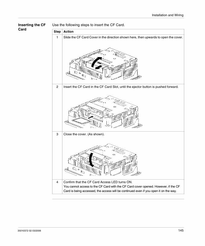
Installation and Wiring
Inserting the CF Card
Use the following steps to insert the CF Card.
Step Action
1 Slide the CF Card Cover in the direction shown here, then upwards to open the cover.
2 Insert the CF Card in the CF Card Slot, until the ejector button is pushed forward.
3 Close the cover. (As shown).
4 Confirm that the CF Card Access LED turns ON.You cannot access to the CF Card with the CF Card cover opened. However, if the CF Card is being accessed, the access will be continued even if you open it on the way.
35010372 02 03/2006 145

Installation and Wiring
Removing the CF Card
Simply reverse the steps shown in the previous "inserting CF Card" explanation.
Prior to removing the CF Card, confirm that the CF Card Access LED is turned OFF.
The following figure displays how to remove the CF Card:
CF Card Handling
The CF card has a life expectancy of 100,000 write cycles. Therefore, be sure to back up all CF Card data regularly to another storage media. (100,000 times assumes the overwriting of 500 kilobytes of data in DOS format).
The following table presents two methods to back up data.
Eject Button
If Then And
Your PC is equipped with a PC Card Slot
To view CF Card data on a personal computer, first, insert the CF Card into a CF Card Adaptor XBT ZGADT.
Save data CF Card on the PC.
Your PC is not equipped with a PC Card Slot
Use a standard XBT ZGADT type PC Card or CF Card reader.
Save data CF Card on the PC.
Note: Depending on the setup of your PC, it’s possible that the Card reader may not operate correctly.The connection between a personal computer and CF Card reader has been tested using an Windows® compatible machine. Check that CF Card reader is correctly installed and configured. Please contact your PC or CF Card reader manufacturer directly for details.
146 35010372 02 03/2006
Installation and Wiring
4.6 USB Port
At a Glance
Overview This section presents the USB Port.
What's in this Section?
This section contains the following topics:
Topic Page
Presentation 148
USB Data Transfer Cable (XBT ZG935) - USB Driver Installation 149
USB Cable Clamp 153
USB Holder 155
35010372 02 03/2006 147
Installation and Wiring
Presentation
Introduction The following XBT GT units have a USB port:
XBT GT2000 series XBT GT4000 series XBT GT5000 series XBT GT6000 series XBT GT7000 series
Data transfer cable (XBT ZG935) can be attached to the USB port to allow transferring of data from the computer to the XBT GT.
WARNINGRISK OF ELECTRIC SHOCK
To prevent an electric shock, unplug the XBT GT unit’s Power Cord from the 24V DC Power Supply prior to attaching or detaching any connector(s) to or from the XBT GT.
Failure to follow this instruction can result in death, serious injury, or equipment damage.
DANGERRISK OF EXPLOSION
Confirm that USB cable has been attached with the USB Cable Clamp (for XBT GT2000 series) or the USB Holder (for XBT GT4000, 5000, 6000 and 7000 series) before using the USB Host Interface in Hazardous Locations provided in UL1604.
Failure to follow this instruction will result in death, serious injury, or equipment damage.
148 35010372 02 03/2006
Installation and Wiring
USB Data Transfer Cable (XBT ZG935) - USB Driver Installation
Important information CAUTION
RISK OF EQUIPMENT DAMAGE
Follow the procedure described below to prevent damage to the cable connector or the XBT GT unit. When connecting the USB Data Transfer Cable to the PC or to the XBT GT unit,
insert the cable’s connector at the correct 90° angle.
When disconnecting the cable, make sure to hold the connector, not the cable itself.
If the cable is unplugged from the port designated during installation and connected to a different port, the Operating System (OS) will not recognize the new port. Therefore, make sure to always use the port designated during installation.
If the installation does not complete successfully, restart the PC and quit all resident applications before re-installing the software.
Failure to follow this instruction can result in injury or equipment damage.
35010372 02 03/2006 149
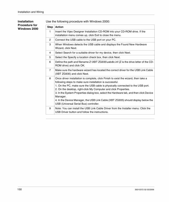
Installation and Wiring
Installation Procedure for Windows 2000
Use the following procedure with Windows 2000:
Step Action
1 Insert the Vijeo Designer Installation CD-ROM into your CD-ROM drive. If the installation menu comes up, click Exit to close the menu.
2 Connect the USB cable to the USB port on your PC.
3 When Windows detects the USB cable and displays the Found New Hardware Wizard, click Next.
4 Select Search for a suitable driver for my device, then click Next.
5 Select the Specify a location check box, then click Next.
6 Define the path and filename Z:\XBT ZG935\usbdlc.inf (Z is the drive letter of the CD-ROM drive) and click OK.
7 Make sure the hardware wizard has located the correct driver for the USB Link Cable (XBT ZG935) and click Next.
8 Once driver installation is complete, click Finish to exist the wizard, then take a following steps to make sure installation is successful.1. On the PC, make sure the USB cable is physically connected to the USB port.2. On the desktop, right-click My Computer and click Properties.3. In the System Properties dialog box, select the Hardware tab, and then click Device Manager. 4. In the Device Manager, the USB Link Cable (XBT ZG935) should display below the USB (Universal Serial Bus) controller.
9 Note: You can install the USB Link Cable Driver from the Installer menu: Click the USB Driver button and follow the instructions.
150 35010372 02 03/2006
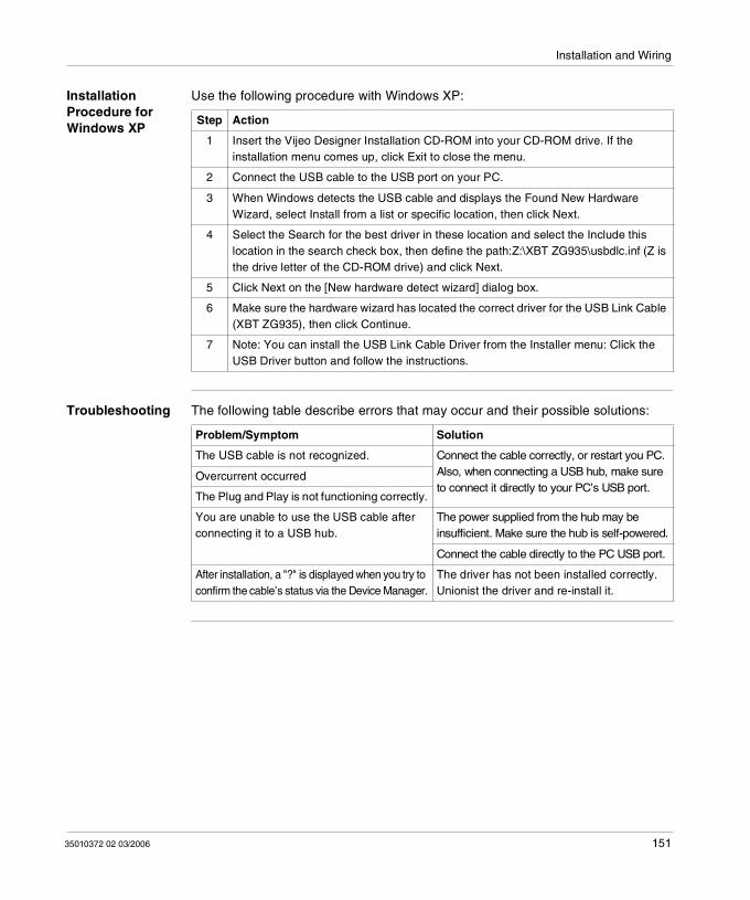
Installation and Wiring
Installation Procedure for Windows XP
Use the following procedure with Windows XP:
Troubleshooting The following table describe errors that may occur and their possible solutions:
Step Action
1 Insert the Vijeo Designer Installation CD-ROM into your CD-ROM drive. If the installation menu comes up, click Exit to close the menu.
2 Connect the USB cable to the USB port on your PC.
3 When Windows detects the USB cable and displays the Found New Hardware Wizard, select Install from a list or specific location, then click Next.
4 Select the Search for the best driver in these location and select the Include this location in the search check box, then define the path:Z:\XBT ZG935\usbdlc.inf (Z is the drive letter of the CD-ROM drive) and click Next.
5 Click Next on the [New hardware detect wizard] dialog box.
6 Make sure the hardware wizard has located the correct driver for the USB Link Cable (XBT ZG935), then click Continue.
7 Note: You can install the USB Link Cable Driver from the Installer menu: Click the USB Driver button and follow the instructions.
Problem/Symptom Solution
The USB cable is not recognized. Connect the cable correctly, or restart you PC. Also, when connecting a USB hub, make sure to connect it directly to your PC’s USB port.
Overcurrent occurred
The Plug and Play is not functioning correctly.
You are unable to use the USB cable after connecting it to a USB hub.
The power supplied from the hub may be insufficient. Make sure the hub is self-powered.
Connect the cable directly to the PC USB port.
After installation, a "?" is displayed when you try to confirm the cable’s status via the Device Manager.
The driver has not been installed correctly. Unionist the driver and re-install it.
35010372 02 03/2006 151
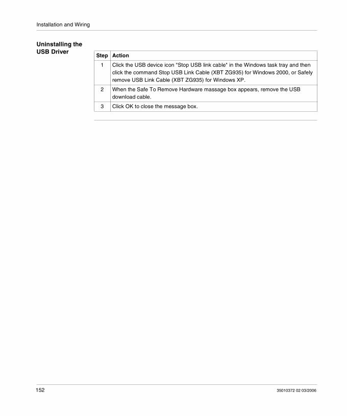
Installation and Wiring
Uninstalling the USB Driver
Step Action
1 Click the USB device icon "Stop USB link cable" in the Windows task tray and then click the command Stop USB Link Cable (XBT ZG935) for Windows 2000, or Safely remove USB Link Cable (XBT ZG935) for Windows XP.
2 When the Safe To Remove Hardware massage box appears, remove the USB download cable.
3 Click OK to close the message box.
152 35010372 02 03/2006
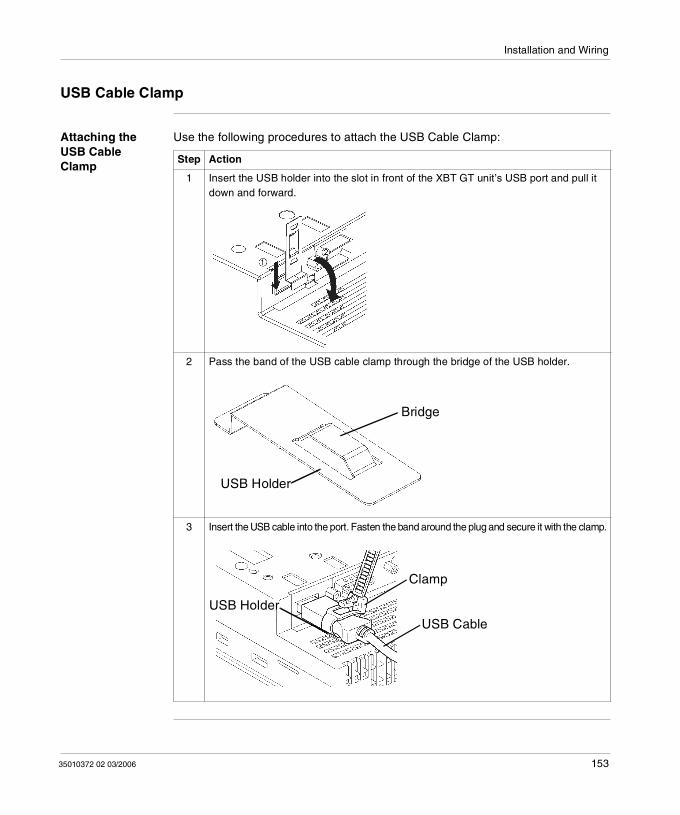
Installation and Wiring
USB Cable Clamp
Attaching the USB Cable Clamp
Use the following procedures to attach the USB Cable Clamp:
Step Action
1 Insert the USB holder into the slot in front of the XBT GT unit’s USB port and pull it down and forward.
2 Pass the band of the USB cable clamp through the bridge of the USB holder.
3 Insert the USB cable into the port. Fasten the band around the plug and secure it with the clamp.
Bridge
USB Holder
Clamp
USB CableUSB Holder
35010372 02 03/2006 153
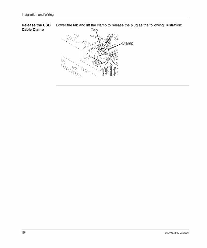
Installation and Wiring
Release the USB Cable Clamp
Lower the tab and lift the clamp to release the plug as the following illustration:
Clamp
Tab
154 35010372 02 03/2006
Installation and Wiring
USB Holder
Introduction When using a USB device, you can attach a USB holder to the USB interface on the side of the XBT GT unit to prevent the USB cable from being disconnected. The USB holder can be used with the following XBT GT:
XBT GT4000 series XBT GT5000 series XBT GT6000 series XBT GT7000 series
WARNINGRISK OF ELECTRIC SHOCK
To prevent an electric shock, unplug the XBT GT unit’s Power Cord from the 24V DC Power Supply prior to attaching or detaching any connector(s) to or from the XBT GT.
Failure to follow this instruction can result in death, serious injury, or equipment damage.
35010372 02 03/2006 155
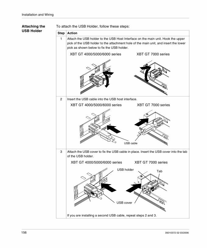
Installation and Wiring
Attaching the USB Holder
To attach the USB Holder, follow these steps:
Step Action
1 Attach the USB holder to the USB Host Interface on the main unit. Hook the upper pick of the USB holder to the attachment hole of the main unit, and insert the lower pick as shown below to fix the USB holder.
2 Insert the USB cable into the USB host interface.
3 Attach the USB cover to fix the USB cable in place. Insert the USB cover into the tab of the USB holder.
If you are installing a second USB cable, repeat steps 2 and 3.
XBT GT 4000/5000/6000 series XBT GT 7000 series
XBT GT 4000/5000/6000 series XBT GT 7000 series
USB cable
XBT GT 4000/5000/6000 series XBT GT 7000 series
USB cover
USB holder Tab
156 35010372 02 03/2006
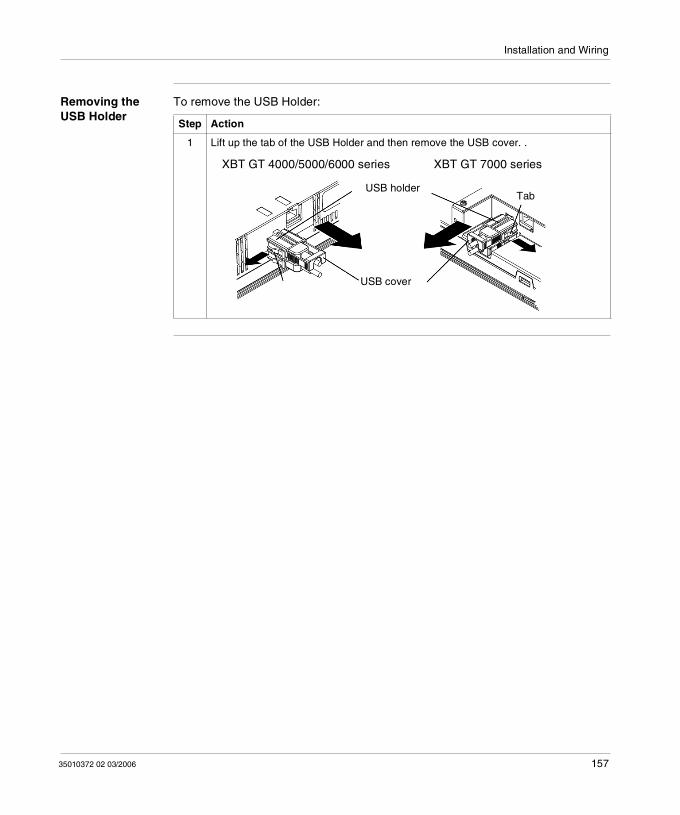
Installation and Wiring
Removing the USB Holder
To remove the USB Holder:
Step Action
1 Lift up the tab of the USB Holder and then remove the USB cover. .
XBT GT 4000/5000/6000 series XBT GT 7000 series
USB cover
USB holderTab
35010372 02 03/2006 157
Installation and Wiring
4.7 AUX Connector
AUX Connector
Introduction You can connect the cable to the AUX Connector to perform an external reset input or a speaker output. The AUX Connector can be used with the following XBT GT units:
XBT GT4000 series XBT GT5000 series XBT GT6000 series XBT GT7000 series
WARNINGRISK OF ELECTRIC SHOCK
To prevent an electric shock, unplug the XBT GT unit’s Power Cord from the 24V DC Power Supply prior to attaching or detaching any connector(s) to or from the XBT GT.
Failure to follow this instruction can result in death, serious injury, or equipment damage.
158 35010372 02 03/2006
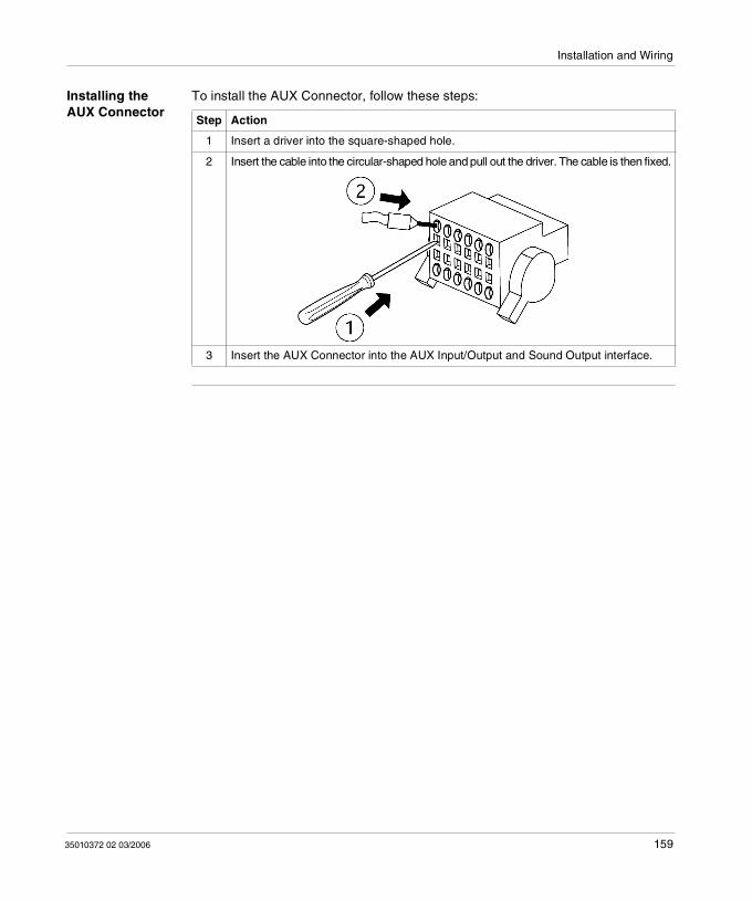
Installation and Wiring
Installing the AUX Connector
To install the AUX Connector, follow these steps:
Step Action
1 Insert a driver into the square-shaped hole.
2 Insert the cable into the circular-shaped hole and pull out the driver. The cable is then fixed.
3 Insert the AUX Connector into the AUX Input/Output and Sound Output interface.
35010372 02 03/2006 159
Installation and Wiring
160 35010372 02 03/2006
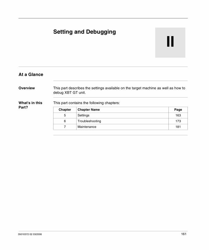
35010372 02 03/2006
II
Setting and DebuggingAt a Glance
Overview This part describes the settings available on the target machine as well as how to debug XBT GT unit.
What's in this Part?
This part contains the following chapters:
Chapter Chapter Name Page
5 Settings 163
6 Troubleshooting 173
7 Maintenance 181
161
Setting and Debugging
162 35010372 02 03/2006
35010372 02 03/2006
5
SettingsAt a Glance
Overview This chapter presents the Settings to be configured on XBT GT unit.
What's in this Chapter?
This chapter contains the following sections:
Section Topic Page
5.1 XBT GT Settings 165
163

Settings
164 35010372 02 03/2006
Settings
5.1 XBT GT Settings
At a Glance
Overview This section describes the settings on all XBT GT units.
What's in this Section?
This section contains the following topics:
Topic Page
Types of Settings 166
Offline Settings 167
System Settings 170
35010372 02 03/2006 165
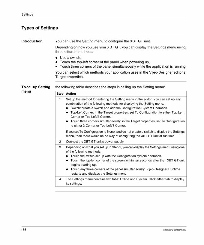
Settings
Types of Settings
Introduction You can use the Setting menu to configure the XBT GT unit.
Depending on how you use your XBT GT, you can display the Settings menu using three different methods:
Use a switch, Touch the top-left corner of the panel when powering up, Touch three corners of the panel simultaneously while the application is running.
You can select which methods your application uses in the Vijeo-Designer editor’s Target properties.
To call up Setting menu
the following table describes the steps in calling up the Setting menu:
Step Action
1 Set up the method for entering the Setting menu in the editor. You can set up any combination of the following methods for displaying the Setting menu. Switch: create a switch and add the Configuration System Operation. Top-Left Corner: in the Target properties, set To Configuration to either Top Left
Corner or Top Left/3 Corner. Touch three corners simultaneously: in the Target properties, set To Configuration
to either 3 Corner or Top Left/3 Corner.
If you set To Configuration to None, and do not create a switch to display the Settings menu, then there would be no way of configuring the XBT GT unit at run time.
2 Connect the XBT GT unit’s power supply.
3 Depending on what you set up in Step 1, you can display the Settings menu using one of the following methods: Touch the switch set up with the Configuration system operation. Touch the top-left corner of the screen within ten seconds after the XBT GT unit
begins starting up. Touch any three corners of the panel simultaneously. Vijeo-Designer Runtime
restarts and displays the Settings menu.
4 The Settings menu contains two tabs: Offline and System. Click either tab to display its settings.
166 35010372 02 03/2006
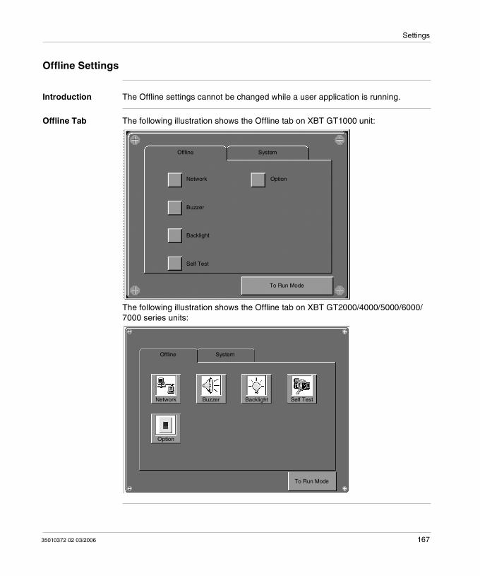
Settings
Offline Settings
Introduction The Offline settings cannot be changed while a user application is running.
Offline Tab The following illustration shows the Offline tab on XBT GT1000 unit:
The following illustration shows the Offline tab on XBT GT2000/4000/5000/6000/7000 series units:
Offline System
To Run Mode
Network
Buzzer
Backlight
Self Test
Option
Offline System
Network Buzzer Backlight Self Test
Option
To Run Mode
35010372 02 03/2006 167
Settings
Network Settings The following table describes how to change the network settings (IP address) on all XBT GT units (except on XBT GT1100).
Touch Buzzer The following table describes how to change the buzzer settings on the XBT GT unit.
Step Action
1 In the Settings menu, touch the Offline tab.
2 Touch the Network icon.
3 Touch any of the three fields (IP Address, Subnet Mask, or Default Gateway) and a keypad will appear.
4 Enter the desired network addresses.
Note: In order for changes to the network settings to take effect, the XBT GT will restart when you touch "To Run Mode" and return to the application.
Step Action
1 In the Settings menu, touch the Offline tab.
2 Touch the Buzzer icon.
3 Touch the desired buzzer mode. The factory setting is When Press Touch object. None: Selecting this will turn the buzzer OFF. When Press Touch Object: The buzzer will only sound when a Touch Object is
touched.
168 35010372 02 03/2006
Settings
Backlight Control
The following table describes how to change the backlight settings on the XBT GT unit.
Self Test Runs test on the XBT GT unit to ensure its various hardware components are operating correctly.
Option Configure the COM1 port as a power supply.
Step Action
1 In the Settings menu, touch the Offline tab.
2 Touch the Backlight icon.
3 In the Backlight Control, define the backlight operations. Wait: To extend the life of the backlight, you can set up the XBT GT so that it turns off
the backlight when the panel is inactive (idle) for the defined period of time, (Idle means the XBT GT panel has not been touched). The factory setting for this item is OFF.
Enable Touch if Backlight is Burned Out: this setting defines whether the touch panel is enabled or disabled when a backlight burnout is detected. When this feature is cleared and the backlight burns out, touch inputs are ignored to prevent operation errors. the factory setting for this item is OFF.
4 To turn the backlight off automatically after a specified period of time, touch the Wait checkbox and then set the idle time.
35010372 02 03/2006 169
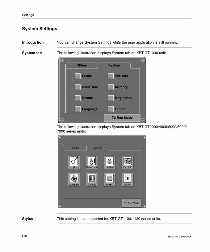
Settings
System Settings
Introduction You can change System Settings while the user application is still running.
System tab The following illustration displays System tab on XBT GT1000 unit:
The following illustration displays System tab on XBT GT2000/4000/5000/6000/7000 series units:
Stylus This setting is not supported for XBT GT1100/1130 series units.
To Run Mode
Offline System
Stylus
Date/Time
Restart
Language
Ver. Info
Memory
Brightness
Option
Offline System
Stylus
To Run Mode
Date/Time Restart Ver. Info
Langage Memory Bright- Option
170 35010372 02 03/2006
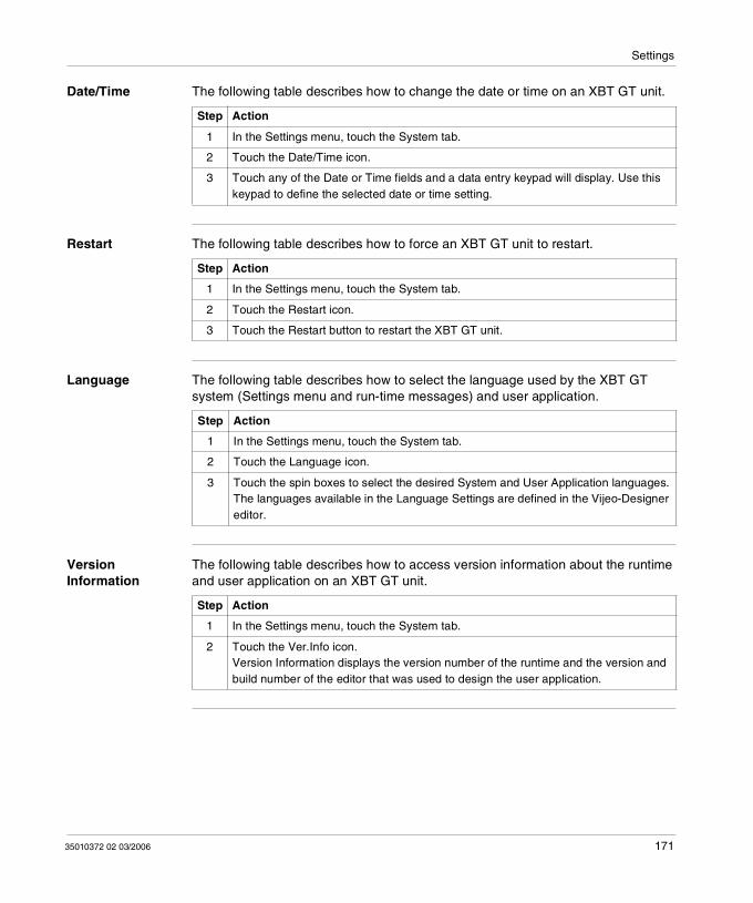
Settings
Date/Time The following table describes how to change the date or time on an XBT GT unit.
Restart The following table describes how to force an XBT GT unit to restart.
Language The following table describes how to select the language used by the XBT GT system (Settings menu and run-time messages) and user application.
Version Information
The following table describes how to access version information about the runtime and user application on an XBT GT unit.
Step Action
1 In the Settings menu, touch the System tab.
2 Touch the Date/Time icon.
3 Touch any of the Date or Time fields and a data entry keypad will display. Use this keypad to define the selected date or time setting.
Step Action
1 In the Settings menu, touch the System tab.
2 Touch the Restart icon.
3 Touch the Restart button to restart the XBT GT unit.
Step Action
1 In the Settings menu, touch the System tab.
2 Touch the Language icon.
3 Touch the spin boxes to select the desired System and User Application languages.The languages available in the Language Settings are defined in the Vijeo-Designer editor.
Step Action
1 In the Settings menu, touch the System tab.
2 Touch the Ver.Info icon.Version Information displays the version number of the runtime and the version and build number of the editor that was used to design the user application.
35010372 02 03/2006 171
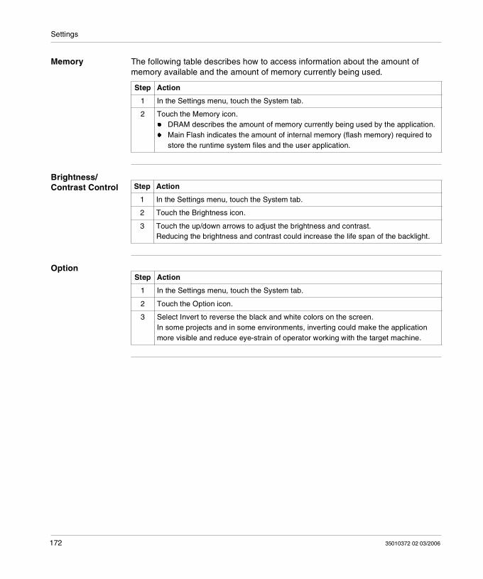
Settings
Memory The following table describes how to access information about the amount of memory available and the amount of memory currently being used.
Brightness/Contrast Control
Option
Step Action
1 In the Settings menu, touch the System tab.
2 Touch the Memory icon. DRAM describes the amount of memory currently being used by the application. Main Flash indicates the amount of internal memory (flash memory) required to
store the runtime system files and the user application.
Step Action
1 In the Settings menu, touch the System tab.
2 Touch the Brightness icon.
3 Touch the up/down arrows to adjust the brightness and contrast.Reducing the brightness and contrast could increase the life span of the backlight.
Step Action
1 In the Settings menu, touch the System tab.
2 Touch the Option icon.
3 Select Invert to reverse the black and white colors on the screen.In some projects and in some environments, inverting could make the application more visible and reduce eye-strain of operator working with the target machine.
172 35010372 02 03/2006
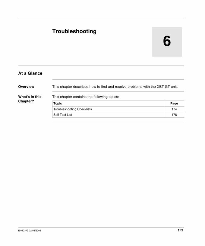
35010372 02 03/2006
6
TroubleshootingAt a Glance
Overview This chapter describes how to find and resolve problems with the XBT GT unit.
What's in this Chapter?
This chapter contains the following topics:
Topic Page
Troubleshooting Checklists 174
Self Test List 178
173
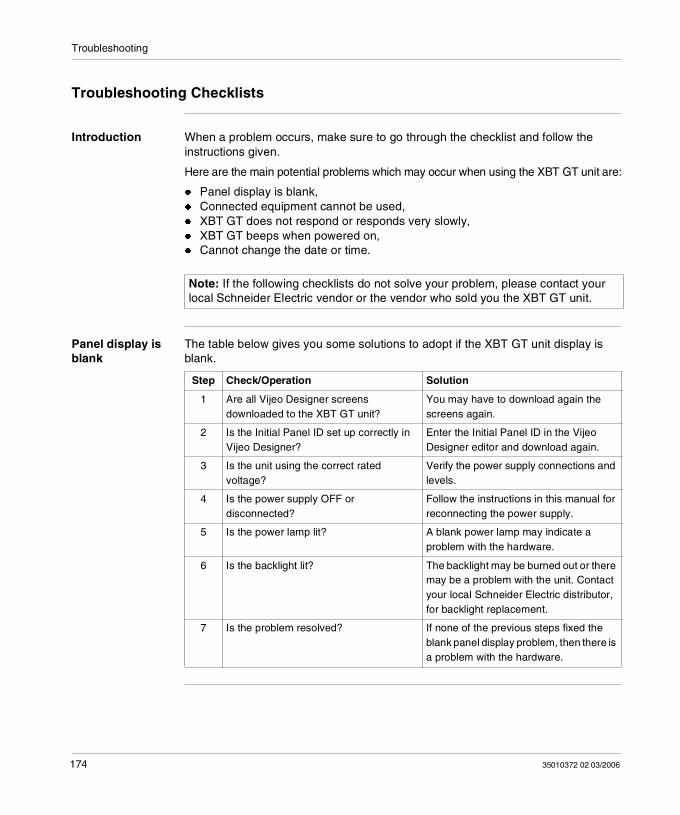
Troubleshooting
Troubleshooting Checklists
Introduction When a problem occurs, make sure to go through the checklist and follow the instructions given.
Here are the main potential problems which may occur when using the XBT GT unit are:
Panel display is blank, Connected equipment cannot be used, XBT GT does not respond or responds very slowly, XBT GT beeps when powered on, Cannot change the date or time.
Panel display is blank
The table below gives you some solutions to adopt if the XBT GT unit display is blank.
Note: If the following checklists do not solve your problem, please contact your local Schneider Electric vendor or the vendor who sold you the XBT GT unit.
Step Check/Operation Solution
1 Are all Vijeo Designer screens downloaded to the XBT GT unit?
You may have to download again the screens again.
2 Is the Initial Panel ID set up correctly in Vijeo Designer?
Enter the Initial Panel ID in the Vijeo Designer editor and download again.
3 Is the unit using the correct rated voltage?
Verify the power supply connections and levels.
4 Is the power supply OFF or disconnected?
Follow the instructions in this manual for reconnecting the power supply.
5 Is the power lamp lit? A blank power lamp may indicate a problem with the hardware.
6 Is the backlight lit? The backlight may be burned out or there may be a problem with the unit. Contact your local Schneider Electric distributor, for backlight replacement.
7 Is the problem resolved? If none of the previous steps fixed the blank panel display problem, then there is a problem with the hardware.
174 35010372 02 03/2006
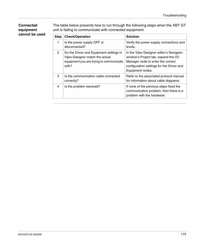
Troubleshooting
Connected equipment cannot be used
The table below presents how to run through the following steps when the XBT GT unit is failing to communicate with connected equipment.
Step Check/Operation Solution
1 Is the power supply OFF or disconnected?
Verify the power supply connections and levels.
2 Do the Driver and Equipment settings in Vijeo-Designer match the actual equipment you are trying to communicate with?
In the Vijeo Designer editor’s Navigator window’s Project tab, expand the I/O Manager node to enter the correct configuration settings for the Driver and Equipment nodes.
3 Is the communication cable connected correctly?
Refer to the associated protocol manual for information about cable diagrams.
4 Is the problem resolved? If none of the previous steps fixed the communication problem, then there is a problem with the hardware.
35010372 02 03/2006 175
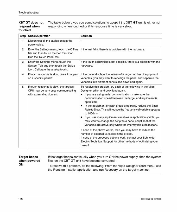
Troubleshooting
XBT GT does not respond when touched
The table below gives you some solutions to adopt if the XBT GT unit is either not responding when touched or if its response time is very slow.
Target beeps when powered ON
If the target beeps continually when you turn ON the power supply, then the system files on the XBT GT unit have become corrupted.
To resolve this problem, do the following: From the Vijeo Designer Start menu, use the Runtime Installer application and run Recovery on the target machine.
Step Check/Operation Solution
1 Disconnect all the cables except the power cable.
-
2 Enter the Settings menu, touch the Offline tab and then touch the Self Test icon. Run the Touch Panel test.
If the test fails, there is a problem with the hardware.
3 Enter the Settings menu, touch the System Tab and then touch the Stylus icon. Calibrate the analog touch.
If the touch calibration is not possible, there is a problem with the hardware.
4 If touch response is slow, does it happen on a specific panel?
If the panel displays the values of a large number of equipment variables, you may want to redesign the panel and separate the variables into different panels and download again.
5 If touch response is slow, the target’s CPU may be very busy communicating with external equipment.
To resolve this problem, try each of the following in the Vijeo Designer editor and download again. If you are using serial communication, make sure the
communication speed between the target and equipment is optimized.
In the equipment or scan group properties, reduce the Scan Rate to Slow. This will reduce the frequency of variable updates to 1000ms.
If you use many equipment variables in application scripts, you may want to change the script to a panel script so that the variables are active only when the information is necessary.
If none of the above works, then you may have to reduce the number of external variables in the project.If none of the proposed options work, contact your Schneider Electric Technical Support for other methods of optimizing your project.
176 35010372 02 03/2006
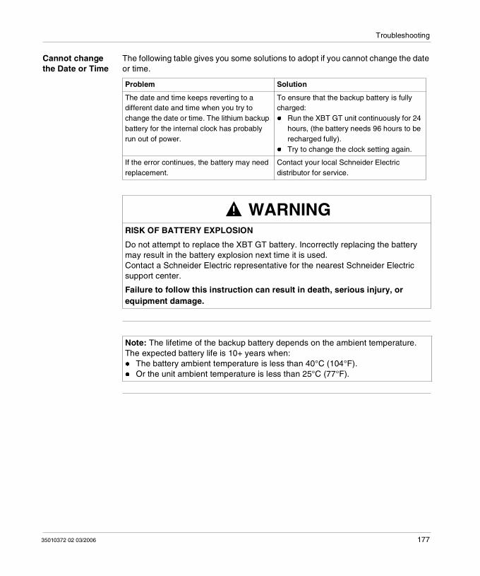
Troubleshooting
Cannot change the Date or Time
The following table gives you some solutions to adopt if you cannot change the date or time.
Problem Solution
The date and time keeps reverting to a different date and time when you try to change the date or time. The lithium backup battery for the internal clock has probably run out of power.
To ensure that the backup battery is fully charged: Run the XBT GT unit continuously for 24
hours, (the battery needs 96 hours to be recharged fully).
Try to change the clock setting again.
If the error continues, the battery may need replacement.
Contact your local Schneider Electric distributor for service.
WARNINGRISK OF BATTERY EXPLOSION
Do not attempt to replace the XBT GT battery. Incorrectly replacing the battery may result in the battery explosion next time it is used. Contact a Schneider Electric representative for the nearest Schneider Electric support center.
Failure to follow this instruction can result in death, serious injury, or equipment damage.
Note: The lifetime of the backup battery depends on the ambient temperature.The expected battery life is 10+ years when: The battery ambient temperature is less than 40°C (104°F). Or the unit ambient temperature is less than 25°C (77°F).
35010372 02 03/2006 177
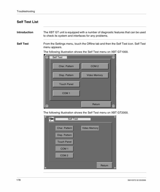
Troubleshooting
Self Test List
Introduction The XBT GT unit is equipped with a number of diagnostic features that can be used to check its system and interfaces for any problems.
Self Test From the Settings menu, touch the Offline tab and then the Self Test icon. Self Test menu appears.
The following illustration shows the Self Test menu on XBT GT1000.
The following illustration shows the Self Test menu on XBT GT2000.
Self Test
Char. Pattern
Return
COM 2
Disp. Pattern Video Memory
Touch Panel
COM 1
Self Test
Char. Pattern
Return
Video Memory
Disp. Pattern
Touch Panel
COM 1
COM 2
178 35010372 02 03/2006
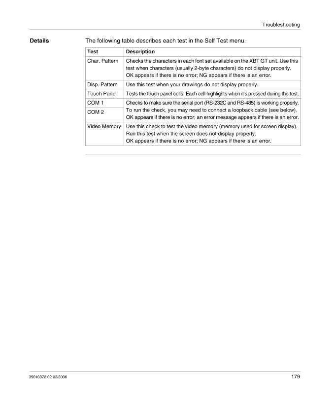
Troubleshooting
Details The following table describes each test in the Self Test menu.
Test Description
Char. Pattern Checks the characters in each font set available on the XBT GT unit. Use this test when characters (usually 2-byte characters) do not display properly.OK appears if there is no error; NG appears if there is an error.
Disp. Pattern Use this test when your drawings do not display properly.
Touch Panel Tests the touch panel cells. Each cell highlights when it’s pressed during the test.
COM 1 Checks to make sure the serial port (RS-232C and RS-485) is working properly.To run the check, you may need to connect a loopback cable (see below).OK appears if there is no error; an error message appears if there is an error.
COM 2
Video Memory Use this check to test the video memory (memory used for screen display). Run this test when the screen does not display properly.OK appears if there is no error; NG appears if there is an error.
35010372 02 03/2006 179
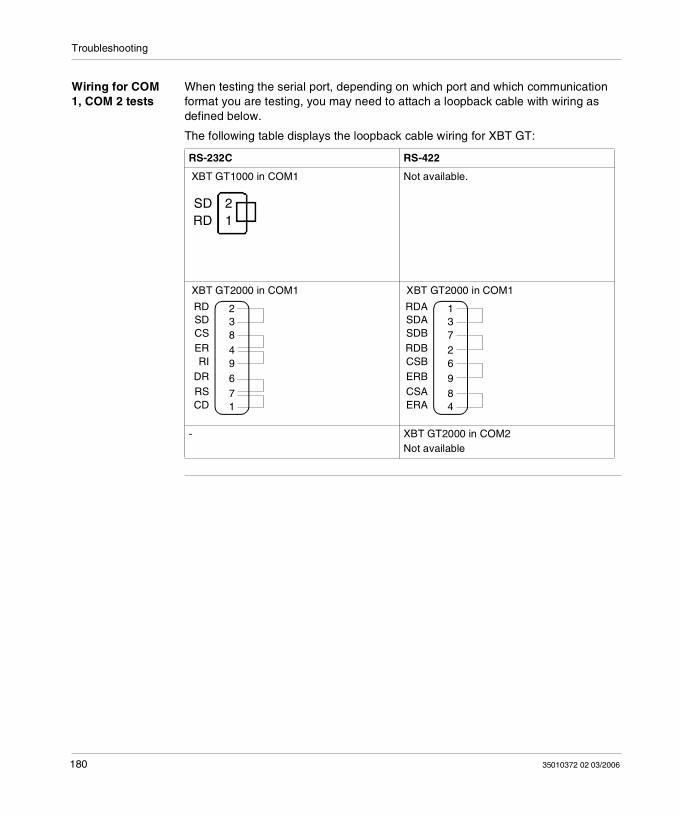
Troubleshooting
Wiring for COM 1, COM 2 tests
When testing the serial port, depending on which port and which communication format you are testing, you may need to attach a loopback cable with wiring as defined below.
The following table displays the loopback cable wiring for XBT GT:
RS-232C RS-422
XBT GT1000 in COM1 Not available.
XBT GT2000 in COM1 XBT GT2000 in COM1
- XBT GT2000 in COM2Not available
21
SDRD
RDSDCSERRI
DRRSCD
23849671
RDASDASDBRDBCSBERBCSAERA
13726984
180 35010372 02 03/2006
35010372 02 03/2006
7
MaintenanceAt a Glance
Overview This chapter explains how to maintain your XBT GT.
What's in this Chapter?
This chapter contains the following topics:
Topic Page
Regular Cleaning 182
Periodic Check Points 184
Replacing the Backlight 185
181
Maintenance
Regular Cleaning
Introduction The regular cleaning is composed of:
Cleaning the front panel, Cleaning the Gasket and procedures.
Cleaning the display
When the surface or the frame of the display gets dirty, soak a soft cloth in water with a neutral detergent, wring the cloth tightly, and wipe the display.
Cleaning the Gasket
The gasket protects the XBT GT and improves its water resistance.
A gasket which has been used for a long period of time may have scratches or dirt on it, and could have lost much of its water resistance. Be sure to change the gasket at least once a year, or when scratches or dirt become visible.
CAUTIONRISK OF EQUIPMENT DAMAGE
Do not use hard or pointed objects to operate the touch-screen panel, since it can damage the panel surface.Do not use paint thinner, organic solvents, or a strong acid compound to clean the unit.
Failure to follow this instruction can result in injury or equipment damage.
182 35010372 02 03/2006
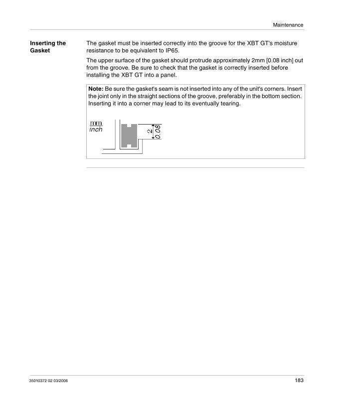
Maintenance
Inserting the Gasket
The gasket must be inserted correctly into the groove for the XBT GT's moisture resistance to be equivalent to IP65.
The upper surface of the gasket should protrude approximately 2mm [0.08 inch] out from the groove. Be sure to check that the gasket is correctly inserted before installing the XBT GT into a panel.
Note: Be sure the gasket's seam is not inserted into any of the unit's corners. Insert the joint only in the straight sections of the groove, preferably in the bottom section. Inserting it into a corner may lead to its eventually tearing.
35010372 02 03/2006 183
Maintenance
Periodic Check Points
Introduction To keep your XB GT unit in its best condition, please, check the following points periodically.
XBT GT Operation Environment, Electrical Specifications, Related Items.
XBT GT Operation Environment
The operating temperature is within the allowable range (0°C to 50°C) (32°F to 122°F)?
The operating humidity is within the specified range (10%RH to 90%RH), dry bulb temperature of 39°C (102°F) or less?
The operating atmosphere is free of corrosive gases?
XBT GT Electrical Specifications
The input voltage is appropriate? DC19.2V to DC28.8V.
Related Items Are all power cords and cables connected properly? Have any become loose? Are all mounting brackets holding the unit securely? Are there many scratches or traces of dirt on the installation gasket?
184 35010372 02 03/2006
Maintenance
Replacing the Backlight
Introduction The XBT GT1000/2000/4000 series units’ backlight cannot be replaced by the customer. When the backlights need to be replaced, please contact your local XBT GT distributor.
The XBT GT5000/6000/7000 series units’ backlight can be replaced by the customer. Please see the Instruction Sheet that comes with replacement backlights for details on how to replace the backlight. Contact your local XBT GT distributor for more information.
How to Determine if the Backlight is Burned Out
If your XBT GT unit's backlight suddenly turns OFF, use the following steps to determine if the backlight is actually burned out:
If the XBT GT unit's "Backlight Control" is not set and the screen has gone blank, your backlight is burned out.
If the XBT GT unit's "Backlight Control" is set to Standby Mode and the screen has gone blank, and touching the screen or performing another input operation does not cause the display to reappear, your backlight is burned out.
WARNINGRISK OF UNINTENDED EQUIPMENT OPERATION
Do not create XBT GT touch panel switches for system functions that may cause injury and/or equipment damage.If the XBT GT unit's backlight burns out and the unit is not set to Standby Mode, the touch panel remains active. If the operator fails to notice that the backlight is burned out and touches the panel, unintended equipment operation can occur.
Failure to follow this instruction can result in death, serious injury, or equipment damage.
35010372 02 03/2006 185
Maintenance
186 35010372 02 03/2006
CBAIndex
AAccessories, 29AUX Connector, 158
CCE Marking, 23CF Card
Installation, 143Removal, 146
Clock, 45Connecting the Power Cord, 127Connecting the Power Supply, 130
DDip Switches, 80
EEdit Mode Peripherals, 26Ethernet
Cable connector, 141Interface, 48
FFasteners, 114
35010372 02 03/2006
GGrounding, 132
IInstallation
CF Card, 143Fasteners, 114Procedures, 119USB Driver, 137
MMaintenance
Check points, 184Cleaning, 182Replacing the backlight, 185
Memory, 45
OOffline Settings, 167
PPanel Cut Dimensions, 113
187
Index
Part numberXBT GT1100, 14XBT GT1130, 14XBT GT2110, 14XBT GT2120, 14XBT GT2130, 14XBT GT2220, 14XBT GT2330, 14XBT GT4230, 14XBT GT4330, 14XBT GT4340, 14XBT GT5230, 14XBT GT5330, 14XBT GT5340, 14XBT GT6330, 14XBT GT6340, 14XBT GT7340, 14
Parts Identification and Functions, 58Peripherals
Edit Mode, 26Run Mode, 28
Power plug, 128
RRun Mode Peripherals, 28
SSelector Switches, 80Self Test, 178Settings
menu, 166Specifications
COM1, 47, 50COM2, 48, 54Display, 42Electrical, 36Enviromental, 37Ethernet, 48Interfaces, 47Memory, 48Structural, 39USB, 48
Standards, 20STN, 42
188
System Settings, 170
TTFT, 43Tool Port Connector, 136Touch panel, 46Troubleshooting, 174
UUSB
Cable Clamp, 153Data Transfer Cable, 149Driver Installation, 137Holder, 155Port, 148
XXBT GT1100
Dimensions, 85Offline Settings, 167Panel Cut Dimensions, 113Parts Identification, 58System Settings, 170
XBT GT1130Dimensions, 85Offline Settings, 167Panel Cut Dimensions, 113Parts Identification, 58System Settings, 170
XBT GT2100Offline Settings, 167Panel Cut Dimensions, 113System Settings, 170
XBT GT2110Dimensions, 88Parts Identification, 60
XBT GT2120Dimensions, 88Offline Settings, 167Panel Cut Dimensions, 113Parts Identification, 60System Settings, 170
35010372 02 03/2006
Index
XBT GT2130Dimensions, 88Offline Settings, 167Panel Cut Dimensions, 113Parts Identification, 60System Settings, 170
XBT GT2220Dimensions, 88Offline Settings, 167Panel Cut Dimensions, 113Parts Identification, 60System Settings, 170
XBT GT2320Parts Identification, 60
XBT GT2330Dimensions, 88Offline Settings, 167Panel Cut Dimensions, 113System Settings, 170
XBT GT4230Dimensions, 92Offline Settings, 167Panel Cut Dimensions, 113System Settings, 170
XBT GT4320Dimensions, 92Offline Settings, 167Panel Cut Dimensions, 113Parts Identification, 63System Settings, 170
XBT GT4330Dimensions, 92Offline Settings, 167Panel Cut Dimensions, 113Parts Identification, 63System Settings, 170
XBT GT5230Dimensions, 96Offline Settings, 167Panel Cut Dimensions, 113Parts Identification, 66System Settings, 170
35010372 02 03/2006
XBT GT5330Dimensions, 100Offline Settings, 167Panel Cut Dimensions, 113Parts Identification, 68System Settings, 170
XBT GT5340Dimensions, 100Offline Settings, 167Panel Cut Dimensions, 113Parts Identification, 68System Settings, 170
XBT GT6330Dimensions, 104Offline Settings, 167Panel Cut Dimensions, 113Parts Identification, 72System Settings, 170
XBT GT6340Dimensions, 104Offline Settings, 167Panel Cut Dimensions, 113Parts Identification, 72System Settings, 170
XBT GT7340Dimensions, 108Offline Settings, 167Panel Cut Dimensions, 113Parts Identification, 76System Settings, 170
189

Index
190
35010372 02 03/2006![infoPLC net Tutorial Magelis [Modo de compatibilidad] · Software Installation Software Set-up Hardware Set-up Magelis Controls Starting the XBT-L1000 Software Modbus Plus Networks](https://img.dokumen.tips/doc/110x75/5b0759917f8b9abf568e5f66/infoplc-net-tutorial-magelis-modo-de-compatibilidad-installation-software-set-up.jpg)


![infoPLC net Tutorial Magelis [Modo de compatibilidad]€¦ · 8 Hardware Set-up Power Connection and PC to Magelis XBT-Z915 (V2.2) XBT-Z962 4 3 2 4 V + - 1 ˛ 9 66"˙ ˙ 0: ’& ˇ](https://img.dokumen.tips/doc/110x75/5ead2fbd24fbbe3f95796ae0/infoplc-net-tutorial-magelis-modo-de-compatibilidad-8-hardware-set-up-power-connection.jpg)