Embed Size (px)
Citation preview

APRILIA WOULD LIKE TO THANK YOU
for choosing one of its products. We have compiled this booklet to provide a comprehensive overview of your vehicle's quality features. Please read itcarefully before riding the vehicle for the first time. It contains information, tips and precautions for using your vehicle. It also describes features, detailsand devices to assure you that you have made the right choice. We believe that if you follow our suggestions, you will soon get to know your new vehiclewell and that it will continue to give you satisfactory service for many years to come. This booklet is an integral part of the vehicle and must be handedover to the new owner in the event of sale.
Tuono V4
Ed. 02_05/2012

The instructions given in this booklet are intended to provide a clear, simple guide to using your scooter; it also describes routine maintenance proceduresand regular checks that should be carried out on the vehicle at an authorised aprilia Dealer or Workshop. This booklet also contains instructions forsimple repairs. Any operations not specifically described in this booklet require the use of special tools and/or particular technical knowledge: for theseoperations, please take your vehicle to an Aprilia Dealer or Authorised Workshop.
2

Personal safety
Failure to completely observe these instructions will result in serious risk of personalinjury.
Safeguarding the environment
Sections marked with this symbol indicate the correct use of the vehicle to prevent dam-aging the environment.
Vehicle intactness
The incomplete or non-observance of these regulations leads to the risk of seriousdamage to the vehicle and sometimes even the invalidity of the guarantee
The symbols illustrated above are very important. They are used to highlight parts of thebooklet that should be read with particular care. The different symbols are used to makeeach topic in the manual simple and quick to locate. Before starting the engine, read thisbooklet carefully, particularly the "SAFE RIDING" section. Your safety as well as other'sdoes not only depend on the quickness of your reflexes and agility, but also on how wellyou know your vehicle, the state of maintenance of the vehicle itself and your knowledgeof the rules for SAFE RIDING. For your safety, get to know your vehicle well so as tosafely ride and master it given any riding condition. IMPORTANT This booklet is anintegral part of the vehicle, and should the vehicle be sold, it must be transferred to thenew owner.
3

4

INDEX
GENERAL RULES....................................................................... 7Foreword............................................................................... 8Carbon monoxide.................................................................. 8Fuel....................................................................................... 8Hot components.................................................................... 9Coolant.................................................................................. 9Used engine oil and gearbox oil............................................ 10Brake and clutch fluid............................................................ 11Battery hydrogen gas and electrolyte.................................... 11Stand..................................................................................... 12Reporting of defects that affect safety................................... 12
System a-PRC (Aprilia Performance Ride Control).................. 13VEHICLE...................................................................................... 15
Arrangement of the main components...................................... 17Dashboard................................................................................ 19Analog instrument panel........................................................... 20Light unit................................................................................... 21Digital lcd display...................................................................... 22
Alarms................................................................................... 26Mapping selection................................................................. 28Control buttons...................................................................... 31Advanced functions............................................................... 32Ignition switch........................................................................ 42Locking the steering wheel.................................................... 43
a-PRC setting buttons............................................................... 43Horn button............................................................................... 44Switch direction indicators........................................................ 45High/low beam selector............................................................. 46Passing button.......................................................................... 46Start-up button.......................................................................... 47Engine stop switch.................................................................... 47System a-PRC (Aprilia Performance Ride Control).................. 47
Immobilizer system operation................................................ 56
Opening the saddle............................................................... 57Glove/tool kit compartment.................................................... 59
Identification.............................................................................. 59USE.............................................................................................. 61
Checks...................................................................................... 62Refuelling.................................................................................. 65Rear shock absorbers adjustment............................................ 66
Rear shock absorbers setting................................................ 68Front fork adjustment................................................................ 70
Front fork setting................................................................... 71Steering shock absorber adjustment........................................ 73Justering af greb til forbremse.................................................. 74Clutch lever adjustment............................................................ 75Running in................................................................................. 75Starting up the engine............................................................... 76Moving off / riding...................................................................... 79Stopping the engine.................................................................. 84Parking...................................................................................... 84Catalytic silencer....................................................................... 85Stand......................................................................................... 86Suggestion to prevent theft....................................................... 87Basic safety rules...................................................................... 88
MAINTENANCE........................................................................... 93Foreword................................................................................... 94
Engine oil level check............................................................ 94Engine oil top-up................................................................... 95
Tyres......................................................................................... 96Spark plug dismantlement........................................................ 97Cooling fluid level...................................................................... 98
Coolant check........................................................................ 99Coolant top-up....................................................................... 99
Checking the brake oil level...................................................... 100Braking system fluid top up................................................... 100
5

Battery removal..................................................................... 103Use of a new battery............................................................. 104Checking the electrolyte level................................................ 105Charging the battery.............................................................. 105
Long periods of inactivity.......................................................... 106Fuses........................................................................................ 107Lamps....................................................................................... 110
Headlight adjustment............................................................. 112Front direction indicators........................................................... 114Rear optical unit........................................................................ 114Rear turn indicators................................................................... 115Number plate light..................................................................... 115Brake light................................................................................. 115Rear-view mirrors...................................................................... 116Front and rear disc brake.......................................................... 117Periods of inactivity................................................................... 118Cleaning the vehicle.................................................................. 119Transport................................................................................... 122
Chain backlash check........................................................... 123Chain backlash adjustment................................................... 124Checking wear of chain, front and rear sprockets................. 124Chain lubrication and cleaning.............................................. 125
TECHNICAL DATA...................................................................... 127Kit equipment............................................................................ 137
PROGRAMMED MAINTENANCE............................................... 139Scheduled maintenance table................................................... 140
6

Tuono V4
Chap. 01General rules
7

Foreword
NOTE
CARRY OUT THE MAINTENANCE OPERATIONS AT HALF THE INTERVALSSPECIFIED IF THE VEHICLE IS USED IN WET OR DUSTY AREAS, OFF ROADOR FOR SPORTING APPLICATIONS.
Carbon monoxide
If you need to keep the engine running in order to perform a procedure, please ensurethat you do so in an open or very well ventilated area. Never let the engine run in anenclosed area. If you do work in an enclosed area, make sure to use a smoke-ex-traction system.
CAUTION
EXHAUST EMISSIONS CONTAIN CARBON MONOXIDE, A POISONOUS GASWHICH CAN CAUSE LOSS OF CONSCIOUSNESS AND EVEN DEATH.
Fuel
CAUTION
THE FUEL USED TO POWER INTERNAL COMBUSTION ENGINES IS HIGHLYFLAMMABLE AND MAY BE EXPLOSIVE UNDER CERTAIN CONDITIONS. IT ISTHEREFORE RECOMMENDED TO CARRY OUT REFUELLING AND MAINTE-NANCE PROCEDURES IN A VENTILATED AREA WITH THE ENGINE SWITCHED
8
1 G
ener
al ru
les

OFF. DO NOT SMOKE DURING REFUELLING OR NEAR FUEL VAPOUR. AVOIDANY CONTACT WITH NAKED FLAME, SPARKS OR OTHER HEAT SOURCESWHICH MAY CAUSE IGNITION OR EXPLOSION.
DO NOT ALLOW FUEL TO DISPERSE INTO THE ENVIRONMENT.
KEEP OUT OF THE REACH OF CHILDREN.
IF THE VEHICLE FALLS OR IS ON A STEEP INCLINE FUEL CAN LEAK.
Hot components
The engine and the exhaust system components get very hot and remain in this con-dition for a certain time interval after the engine has been switched off. Before handlingthese components, make sure that you are wearing insulating gloves or wait until theengine and the exhaust system have cooled down.
Coolant
The coolant contains ethylene glycol which, under certain conditions, can becomeflammable. When ethylene glycol burns, it produces an invisible flame which can nev-ertheless cause burns.
CAUTION
TAKE CARE NOT TO SPILL COOLANT ONTO HOT ENGINE OR EXHAUST SYS-TEM COMPONENTS; THE FLUID MAY IGNITE AND BURN WITH AN INVISIBLE
9
1 General rules

FLAME. WHEN CARRYING OUT MAINTENANCE, IT IS ADVISABLE TO WEARLATEX GLOVES. EVEN THOUGH IT IS TOXIC, COOLANT HAS A SWEET FLA-VOUR WHICH MAKES IT VERY ATTRACTIVE TO ANIMALS. NEVER LEAVE THECOOLANT IN OPEN CONTAINERS IN AREAS ACCESSIBLE TO ANIMALS ASTHEY MAY DRINK IT.
KEEP OUT OF THE REACH OF CHILDREN.
DO NOT REMOVE THE RADIATOR CAP WHEN THE ENGINE IS STILL HOT. THECOOLANT IS PRESSURISED AND MAY CAUSE SCALDING.
Used engine oil and gearbox oil
CAUTION
IT IS ADVISABLE TO WEAR LATEX GLOVES WHEN SERVICING THE VEHICLE.
THE ENGINE OR GEARBOX OIL MAY CAUSE SERIOUS INJURIES TO THE SKINIF HANDLED FOR PROLONGED PERIODS OF TIME AND ON A REGULAR BA-SIS.
WASH YOUR HANDS CAREFULLY AFTER HANDLING OIL.
HAND THE OIL OVER TO OR HAVE IT COLLECTED BY THE NEAREST USEDOIL RECYCLING COMPANY OR THE SUPPLIER.
DO NOT DISPOSE OF OIL IN THE ENVIRONMENT
KEEP OUT OF THE REACH OF CHILDREN.
10
1 G
ener
al ru
les

Brake and clutch fluid
BRAKE FLUID MAY BE HARMFUL TO PAINTWORK, PLASTIC AND RUBBER.WHEN SERVICING THE BRAKING SYSTEM PROTECT THESE COMPONENTSWITH A CLEAN CLOTH. ALWAYS WEAR PROTECTIVE GOGGLES WHEN SERV-ICING THESE SYSTEMS. BRAKE FLUID IS EXTREMELY HARMFUL TO THEEYES. IN THE EVENT OF ACCIDENTAL CONTACT WITH THE EYES, RINSETHEM IMMEDIATELY WITH ABUNDANT COLD, CLEAN WATER AND SEEKMEDICAL ADVICE.
KEEP OUT OF THE REACH OF CHILDREN
Battery hydrogen gas and electrolyte
CAUTION
THE BATTERY ELECTROLYTE IS TOXIC, CORROSIVE AND, AS IT CONTAINSSULPHURIC ACID, MAY CAUSE BURNING IF IT COMES INTO CONTACT WITHTHE SKIN. WHEN HANDLING BATTERY ELECTROLYTE, WEAR TIGHT-FITTINGGLOVES AND PROTECTIVE APPAREL. IN THE EVENT OF SKIN CONTACT WITHTHE ELECTROLYTIC FLUID, RINSE WELL WITH PLENTY OF CLEAN WATER. ITIS PARTICULARLY IMPORTANT TO PROTECT YOUR EYES BECAUSE EVENTINY AMOUNTS OF BATTERY ACID MAY CAUSE BLINDNESS. IN THE EVENTOF CONTACT WITH THE EYES, RINSE WITH PLENTY OF WATER FOR FIFTEENMINUTES AND CONSULT AN EYE SPECIALIST IMMEDIATELY. IF THE FLUID ISACCIDENTALLY SWALLOWED, DRINK LARGE QUANTITIES OF WATER ORMILK, FOLLOWED BY MILK OF MAGNESIA OR VEGETABLE OIL AND SEEKMEDICAL ADVICE IMMEDIATELY. THE BATTERY RELEASES EXPLOSIVEGASES; KEEP IT AWAY FROM FLAMES, SPARKS, CIGARETTES OR ANY OTH-
11
1 General rules

ER HEAT SOURCES. ENSURE ADEQUATE VENTILATION WHEN SERVICINGOR RECHARGING THE BATTERY.
KEEP OUT OF THE REACH OF CHILDREN.
BATTERY LIQUID IS CORROSIVE. DO NOT POUR IT OR SPILL IT, PARTICU-LARLY ON PLASTIC COMPONENTS. ENSURE THAT THE ELECTROLYTIC ACIDIS COMPATIBLE WITH THE BATTERY BEING ACTIVATED.
Stand
BEFORE SETTING OFF, MAKE SURE THE STAND HAS BEEN COMPLETELYRETRACTED TO ITS POSITION.
DO NOT REST THE RIDER OR PASSENGER WEIGHT ON THE SIDE STAND.
Reporting of defects that affect safety
Unless otherwise specified in this Use and Maintenance Booklet, do not remove anymechanical or electrical component.
CAUTION
SOME OF THE VEHICLE'S CONNECTORS ARE INTERCHANGEABLE AND IFMOUNTED INCORRECTLY CAN JEOPARDISE REGULAR FUNCTIONING OFTHE VEHICLE AND/OR DAMAGE PARTS OF IT IRREPARABLY.
12
1 G
ener
al ru
les

System a-PRC (Aprilia Performance Ride Control)
(if applicable)
a-PRC system (Aprilia Performance Ride Control)
The a-PRC system consists of the following control systems:
ALC (Aprilia Launch Control)
A system designed to help the rider optimise acceleration during standing starts.
ATC (Aprilia Traction Control)
A system designed to help the rider control wheelspin.
AWC (Aprilia Wheelie Control)
A system designed to help the rider control wheeling by reducing torque to gently lowerthe front wheel to the ground.
AQS (Aprilia Quick Shift)
This system enables upshifts without using the clutch and without changing the throttleposition.
key:
a-PRC: motorcycle with a-PRC system (Aprilia Performance Ride Control)
std: motorcycle without a-PRC system (Aprilia Performance Ride Control)
13
1 General rules

14
1 G
ener
al ru
les

Tuono V4
Chap. 02Vehicle
15

02_01
16
2 Ve
hicl
e

02_02
Arrangement of the main components (02_02)
key:
1. Left side fairing2. Left turn indicator3. Horn4. Left headlamp5. CLF ECU (Tone wheel reading control unit) (if fitted)6. Windshield7. Steering damper (if fitted)8. Clutch lever9. Left rear-view mirror10. Left hand switch11. Fuel tank cap
17
2 Vehicle

12. Fuel tank13. Left side fairing14. Battery15. Auxiliary fuses16. Main fuses17. Taillight18. License plate light19. Rear left turn indicator20. Saddle / glovebox / toolkit compartment lock21. Left hand passenger footrest22. Left hand rider footrest23. Side stand24. Gear lever25. AQS (Aprilia Quick Shift) (if fitted)26. Left hand fairing lug27. Engine oil radiator28. Coolant radiator29. Rear right turn indicator30. Passenger seat31. Right side fairing32. Rider saddle33. Sensor box (inertia sensor platform) (if fitted)34. Air filter35. ECU36. Right hand switch37. Right rear-view mirror38. Front brake fluid reservoir39. Front brake lever40. Instrument/indicator light panel41. Front right headlamp42. Front right turn indicator43. Expansion tank cap44. Coolant expansion tank45. Right side fairing46. Front tone wheel (if applicable)47. Gear lever48. Right hand rider footrest49. Rear brake pump and fluid reservoir
18
2 Ve
hicl
e
50. Rear tone wheel (if applicable)51. Right hand passenger footrest
02_03
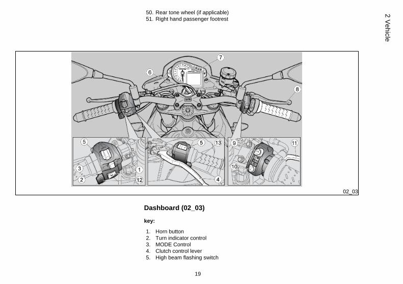
Dashboard (02_03)
key:
1. Horn button2. Turn indicator control3. MODE Control4. Clutch control lever5. High beam flashing switch
19
2 Vehicle

6. Ignition switch /steering lock7. Instruments and gauges8. Throttle grip9. Engine stop button10. Starter button11. Front brake lever12. "+" button (if applicable)13. "-" button (if applicable)
02_04
02_05
Analog instrument panel (02_04, 02_05)
key:
1. Rpm indicator2. Multifunctional digital display3. Warning lights
20
2 Ve
hicl
e

The instrument panel has an immobilizer system which prevents start-up in case thesystem does not identify a key which has been stored before.
The vehicle is supplied with two keys already programmed. The instrument panel ac-cepts a maximum of four keys at the same time: contact an Official Aprilia Dealer toenable these keys or to disable a key that has been lost. When the vehicle is deliveredand approximately ten seconds after the key is set to ON, the instrument panel re-quests a personal five-digit code to be entered. This request is no longer displayedonce the personal code is entered. For code entering procedure, see the CODEMODIFICATION section
It is important to remember the personal code because:
• the vehicle can be started if the immobilizer system is faulty• the instrument panel need not be replaced should the ignition switch
be changed• new keys can be programmed
02_06
Light unit (02_06)
key:
1. General warning light, red2. Gear in neutral warning light, green3. a-PRC (Aprilia Performance Ride Control) indicator light, orange (if enabled)4. Low fuel warning light, orange5. Right turn indicator warning light, green6. ABS warning light (not enabled)7. Gear shift warning light, red8. Left turn indicator warning light, green9. High beam indicator light, blue.
21
2 Vehicle

02_07
02_08
Digital lcd display (02_07, 02_08, 02_09, 02_10, 02_11, 02_12,02_13, 02_14, 02_15)
• By turning the ignition key to 'KEY ON', the following indicators on the instru-ment panel are lit for two seconds:
- The 'Tuono V4' logo
- All warning lights
• The rpm indicator pointer moves and then goes back to its original position.
NOTE
EVERY TIME THE SELECTOR IS HELD DOWN TO THE RIGHT OR LEFT, YOUCAN GO FROM ONE CONFIGURATION TO ANOTHER.
22
2 Ve
hicl
e

02_09
ROAD - TRIP 1/TRIP 2 MODES (a-PRC)
1) Water temperature (displayed either in °C or °F);
2) Gear selected;
3) Clock (in 24H format or in 12H format with no AM/PM indication) or chronometer(selectable from menu).
4) Map selected;
5) ALC (Aprilia Launch Control);
6) ATC (Aprilia Traction Control); The level is displayed in negative against a blackbackground when AWC (Aprilia Wheelie Control) is active.
7) Speed (speedometer);
8) Information, if available, relative to maps stored in ECU;
9) Service interval spanner symbol, if applicable.
10) Trip computer log or alarms stored.
02_10
RACE MODE (a-PRC)
1) Chronometer or Launch control;
2) Gear selected;
3) Information, if available, relative to maps stored in ECU;
4) Map selected;
5) ATC (Aprilia Traction Control); The level is displayed in negative against a blackbackground when AWC (Aprilia Wheelie Control) is active.
6) Speed (speedometer);
7) Water temperature (displayed either in °C or °F);
23
2 Vehicle

02_11
TRIP 1/TRIP 2 MODE (std)
1) Water temperature (displayed either in °C or °F);
2) Gear selected;
3) Clock (in 24H format or in 12H format with no AM/PM indication) or chronometer(selectable from menu).
4) Map selected;
5) Speed (speedometer);
6) Information, if available, relative to maps stored in ECU;
7) Service interval spanner symbol, if applicable.
8) Trip computer log or alarms stored.
02_12
RACE MODE (std)
1) Chronometer or Launch control;
2) Gear selected;
3) Information, if available, relative to maps stored in ECU;
4) Map selected;
5) Speed (speedometer);
6) Water temperature (displayed either in °C or °F);
24
2 Ve
hicl
e

02_13
Two kilometres after the low fuel warning light turns on, the kilometres travelled withlow fuel are shown on the digital display.
Pressing the centre button of the MODE control while the low fuel warning light isactive temporarily deactivates the warning light for 60 seconds.
At "KEY-ON" the indication of reserve can have a delay of 60 seconds.
02_14
The instrument panel can display instantaneous fuel consumption
The instrument panel can display average fuel consumption since the last journey logreset
Upon entering reserve, the distance in Km (or mi) travelled since entering reservestate is displayed instead of the trip counter
25
2 Vehicle

02_15
When a maintenance interval threshold is exceeded, an icon with a spanner is shown.This indicator may be reset once the scheduled service has been completed by anauthorised Aprilia Dealer or service centre.
The "spanner" icon flashes for five seconds when the key is turned to "KEY ON" whenthere is less than 300 Km (186 mi) remaining before the next scheduled maintenanceinterval.
With the key set to "KEY OFF" the general alarm warning light flashes to indicateactivation of the locking system. To minimise battery consumption the light stopsflashing after 48 hours.
02_16
Alarms (02_16, 02_17, 02_18, 02_19, 02_20)
In case of failure, a different icon is displayed according to the cause at the bottom ofthe display.
Take your vehicle as soon as possible to an Official Aprilia Dealer.
SERVICE ALARM
In case of failure found in the instrument panel or in the electronic control unit, theinstrument panel signals the failure by displaying the SERVICE icon and the red gen-eral warning light comes on.
02_17
If there is an immobilizer failure at ignition, the instrument panel requests you to entera user code. If the code is entered correctly, the instrument panel signals the failureby displaying the SERVICE icon and the red general warning light comes on.
URGENT SERVICE ALARM
A serious failure is signalled by a fast flashing (two flashes per second) of the generalwarning light and by the URGENT and SERVICE words alternately being shown onthe digital display. Take your vehicle as soon as possible to an Official Aprilia Dealer.In these cases, the control unit activates a safety procedure that limits the vehicleperformance so that the rider is able to reach an Official Aprilia Dealer at low speed.According to the type of failure, performance can be limited in two ways: a) by reducing
26
2 Ve
hicl
e

the maximum torque produced; b) by keeping the engine at idle speed but slightlyaccelerated (during this operation, the throttle control is disabled).
02_18
Oil failure
In case of failing oil pressure or oil pressure sensor failure, the bulb and the red generalwarning light turn on the instrument panel.
Engine overheating alarm
The engine overheating alarm is activated when the temperature reaches 115 °C (239°F). It is signalled when the general red warning light turns on.
02_19
Electronic control unit disconnected alarm
In case no connection is detected, the disconnection icon is displayed on the instru-ment panel and the red general warning light turns on to signal this condition.
27
2 Vehicle
02_20
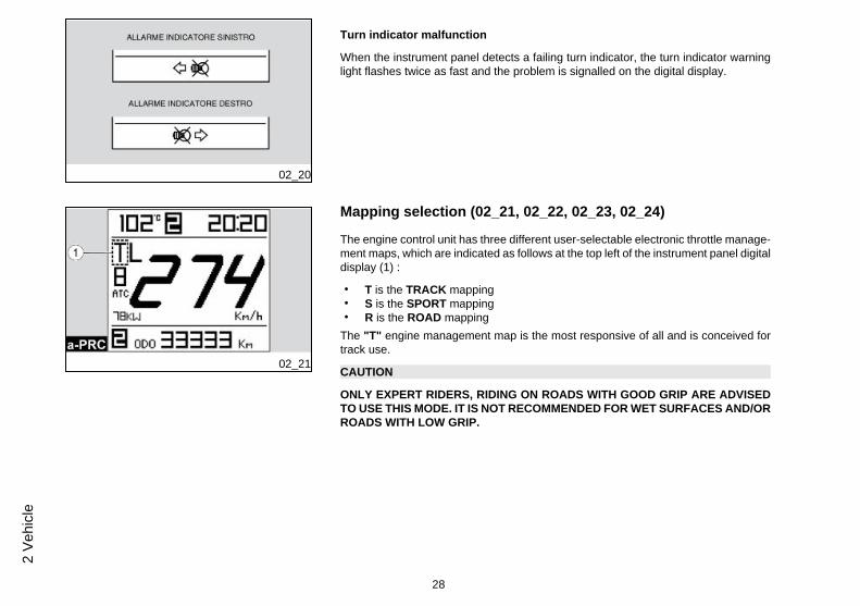
Turn indicator malfunction
When the instrument panel detects a failing turn indicator, the turn indicator warninglight flashes twice as fast and the problem is signalled on the digital display.
02_21
Mapping selection (02_21, 02_22, 02_23, 02_24)
The engine control unit has three different user-selectable electronic throttle manage-ment maps, which are indicated as follows at the top left of the instrument panel digitaldisplay (1) :
• T is the TRACK mapping• S is the SPORT mapping• R is the ROAD mapping
The "T" engine management map is the most responsive of all and is conceived fortrack use.
CAUTION
ONLY EXPERT RIDERS, RIDING ON ROADS WITH GOOD GRIP ARE ADVISEDTO USE THIS MODE. IT IS NOT RECOMMENDED FOR WET SURFACES AND/ORROADS WITH LOW GRIP.
28
2 Ve
hicl
e

02_22
The "S" engine management map is tailored for performance-oriented use. In thismode the vehicle's performance in first and second gear is reduced.
02_23
02_24
The "R" engine management map is designed for normal road use. The system re-duces the maximum torque supplied by the engine and smoothly delivers it so as toprevent loss of grip. In this mode, the vehicle performance is limited, and therefore,the maximum speed cannot be reached.
CAUTION
THIS IS NOT AN ANTI-SKID DEVICE. BE EXTREMELY CAUTIOUS WHEN RIDINGON ROADS WITH LOW GRIP.
29
2 Vehicle

The rider may cycle through the different engine maps by pressing the starter button,which may be used to select maps once 5 seconds have elapsed after engine start.
CAUTION
THE RIDER MAY USE THE STARTER BUTTON TO SELECT MAPS EVEN WITHTHE VEHICLE IN MOTION, PROVIDED THAT THE ENGINE IS RUNNING AND THETHROTTLE IS RELEASED.
To change engine maps, proceed as follows.
• Press the starter button once. The symbol of engine map currently in use isdisplayed in negative against a black background.
• Press the button twice within 1.5 seconds; the next engine map is displayedin negative against a black background. To select this engine map, press thestarter button within 1.5 seconds. Otherwise, the next engine map in the se-quence will be displayed in negative against a black background. When thedesired map is shown, press the starter button and the desired map will bedisplayed normally. In any case, do not "open" the throttle during this oper-ation. If the throttle is opened, the activation process for the new engine mapby the ECU is interrupted (the map symbol is displayed normally and flashing)until the throttle is closed again, allowing the ECU to complete the procedure.
CAUTION
IF THE THROTTLE IS OPENED WHILE A NEW MAP IS DISPLAYED IN NEGATIVEAGAINST A BLACK BACKGROUND (INDICATING THAT IT IS STILL BEING AC-TIVATED BY THE ECU), THE NEW MAP SELECTED WILL START TO FLASH(DISPLAYED NORMALLY) BUT WILL NOT BE EFFECTIVELY APPLIED UNTILTHE THROTTLE IS RELEASED AGAIN.
30
2 Ve
hicl
e

02_25
Control buttons (02_25)
Trip journal 1 and 2
There are two trip journals available.
Press and hold down the MODE control to the left to select the TRIP JOURNAL 1;icon "1" on the DIGITAL DISPLAY turns on.
Press and hold down the MODE control to the right to select the TRIP JOURNAL 2;icon "2" on the DIGITAL DISPLAY turns on.
In each journal, each time the MODE control is briefly pressed to the right or left, thefollowing information is displayed in sequence:
1) ODOMETER;
2) TRIP ODOMETER;
3) JOURNEY TIME;
4) MAXIMUM SPEED;
5) AVERAGE SPEED;
6) AVERAGE FUEL CONSUMPTION;
7) INSTANTANEOUS FUEL CONSUMPTION;
8) MENU (only with vehicle at a standstill)
With the following options: TRIP ODOMETER, TRAVELLING TIME, MAXIMUMSPEED, MEAN SPEED, AVERAGE FUEL CONSUMPTION, press and hold down thecentral key to reset all the indications stored in the active TRIP JOURNAL.
CHRONOMETER
To use the chronometer, select the CHRONOMETER function from the MENU of theinstrument panel advanced functions.
The chronometer appears at the top of the digital display, replacing the clock.
31
2 Vehicle

With the vehicle in motion the chronometer functioning is controlled by means of theMODE control central button.
Press the central button briefly to start the chronometer. Timekeeping starts when thebutton is pressed. If the button is pressed again within 15 seconds after starting time-keeping, the chronometer is reset. After that time, and if the button is pressed again,the data is stored and the next timekeeping begins.
Timekeeping is cancelled by pressing and holding down the central button, or whenspeed goes back to zero; the display shows the last timekeeping. Timekeeping startsagain following the steps described above.
Once 40 timekeeping sessions have been acquired, acquisition stops and the mes-sage "FULL" is shown on the digital display. A new series of timekeeping can bestarted again only after deleting previous times stored by means of the MENU of theinstrument panel advanced functions.
02_26
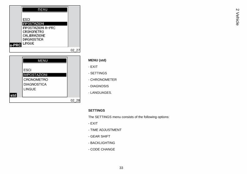
Advanced functions (02_26, 02_27, 02_28, 02_29, 02_30, 02_31,02_32, 02_33, 02_34, 02_35, 02_36)
MENU (a-PRC)
The configuration menu is accessible with the vehicle at a standstill by pressing andholding the MODE button, directly via the menu screen page, and contains the fol-lowing functions:
- EXIT
- SETTINGS
- A-PRC SETTINGS
- CHRONOMETER
- CALIBRATION
- DIAGNOSIS
- LANGUAGES
32
2 Ve
hicl
e
02_27
02_28
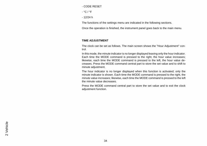
MENU (std)
- EXIT
- SETTINGS
- CHRONOMETER
- DIAGNOSIS
- LANGUAGES.
SETTINGS
The SETTINGS menu consists of the following options:
- EXIT
- TIME ADJUSTMENT
- GEAR SHIFT
- BACKLIGHTING
- CODE CHANGE
33
2 Vehicle
- CODE RESET
- °C / °F
- 12/24 h
The functions of the settings menu are indicated in the following sections.
Once the operation is finished, the instrument panel goes back to the main menu.
TIME ADJUSTMENT
The clock can be set as follows. The main screen shows the "Hour Adjustment" con-trol.In this mode, the minute indicator is no longer displayed leaving only the hour indicator.Each time the MODE command is pressed to the right, the hour value increases;likewise, each time the MODE command is pressed to the left, the hour value de-creases. Press the MODE command central part to store the set value and to shift tominute adjustment.The hour indicator is no longer displayed when this function is activated; only theminute indicator is shown. Each time the MODE command is pressed to the right, theminute value increases; likewise, each time the MODE command is pressed to the leftthe minute value decreases.Press the MODE command central part to store the set value and to exit the clockadjustment function.
34
2 Ve
hicl
e

02_29
GEAR SHIFT THRESHOLD
The gear shift threshold can be set in this mode. The main screen page shows themessage "GEAR SHIFT THRESHOLD".Each time the MODE command is pressed to the right, the threshold value increasesby 100 RPM; vice versa, each time the MODE command is pressed to the left, thethreshold value decreases by 100 RPM.After reaching either the highest or lowest limit, the next time the command is pressedwill produce no effect.The procedure ends when the MODE command is pressed at the central position,which stores the set value, the pointer goes back to zero and the instrument panelgoes back to the configuration menu.When the battery is first activated, the instrument panel is set to the run-in rev value.Afterwards, the last set value is displayed:
• RUN-IN REVOLUTIONS: 8500 rpm• MAXIMUM REVOLUTIONS: 15000 rpm
If the set threshold value is exceeded, the gear change warning light on the instrumentpanel starts to flash. It turns off when the value goes back below the threshold limit.
02_30
BACKLIGHTING BRIGHTNESS
This function adjusts the backlighting brightness to three levels. Each time the MODEcommand is pressed to the right or left, the following icons are shown:
• LOW• MEAN• HIGH
Once the operation is finished, when the MODE command is pressed at central po-sition, the instrument panel shows the SETTINGS menu.
When the battery is detached, the display is configured with the maximum level ofbrightness.
35
2 Vehicle

02_31
02_32
CODE CHANGE
This function is used to modify an old code. Once you have entered this function, thefollowing message is displayed:
"ENTER OLD CODE"
After recognising the old code, the new code is requested and the display shows thefollowing message:
"ENTER NEW CODE"
Once the operation is finished, the display shows the DIAGNOSIS menu. If the codehas been used, this operation is not allowed.
36
2 Ve
hicl
e

Once the operation is finished, the instrument panel shows the SETTINGS menu.
If it is the first time a code is stored, only the new code is requested.
CODE RESET
This function is used to set a new code when the old one is not available; in this case,at least two keys will have to be inserted in the ignition lock. After the first key hasbeen inserted, the second one is requested with the following message:
"INSERT KEY II"
In between keys, the instrument panel remains lit; if the key is not inserted within 20seconds, the operation finishes. After recognising the second key, the insertion of thenew code is required with the message:
"ENTER NEW CODE"
Once the operation is finished, the display shows the DIAGNOSIS menu. If the codehas been used, this operation is not allowed.
Once the operation is finished, the instrument panel shows the SETTINGS menu.
°C/°F
Select the °C / °F option from the SETTINGS menu for this function.
This function selects the unit of measurement for the coolant temperature: °C or °F.
12H / 24H
Select the 12H / 24H option from the SETTINGS menu for this function.
This menu selects the clock display mode as 12h or 24h.
a-PRC SETTINGS (on vehicles with a-PRC)
37
2 Vehicle

NOTE
THIS MODE CAN ONLY BE ACCESSED IF THE ATC (Aprilia Traction Control)SYSTEM IS ACTIVE.
02_33
This mode allows the rider to set/activate AWC (Aprilia Wheelie Control) level and setALC (Aprilia Launch Control) levels, with the vehicle at a standstill.
After selecting the function A-PRC SETTINGS, press the MODE selector briefly toaccess the AWC and ALC level settings screen.
The AWC level is selected automatically and displayed in negative against a blackbackground. Press the "+" and "-" buttons briefly to increase or decrease the levelsetting from "1" (minimum system intervention) to "3" (maximum system intervention).
To deactivate the system, set the minimum level "1" then press and hold "-".
Press and hold "+" to activate again.
02_34
To set the ALC level from the adjustment screen (accessible from A-PRC SETTINGS),push the MODE selector briefly to the left so that the ALC level is displayed in negativeagainst a black background.
Press the "+" and "-" buttons briefly to increase or decrease the ALC level setting from"1" (minimum system intervention) to "3" (maximum system intervention).
CAUTION
TO GAIN FAMILIARITY WITH THE AWC AND ALC SYSTEMS, PREFERABLY USELEVEL "3" TO START WITH. AND THEN, ONCE YOU FEEL COMFORTABLEWITH THE SYSTEMS, TRY THE OTHER LEVELS TO IDENTIFY WHICH ARE THEBEST SUITED TO YOUR RIDING STYLE AND FOR DIFFERENT ROAD ANDWEATHER CONDITIONS.
LEVEL "1" IS RECOMMENDED FOR USE BY EXPERT RIDERS IN IDEAL ROADSURFACE CONDITIONS.
38
2 Ve
hicl
e

LEVEL "2" IS AN INTERMEDIATE SETTING BETWEEN LEVEL "1" AND LEVEL"3".
THE a-PRC SETTING FUNCTION MAY ALSO BE ACCESSED FROM THE RACEDISPLAY MODE BY PRESSING THE MODE SELECTOR BRIEFLY.
CHRONOMETER
Select the CHRONOMETER option from the configuration menu to access the chro-nometer function. When the CHRONOMETER function is selected the screen pageshows the following options:
- EXIT
- CLOCK/CHRONOMETER
- DELETE TIMES
CLOCK/CHRONOMETERThis function allows you to select which function to have at the top of the display: clockor chronometer.
02_35
View times
This option shows the stored chronometer times. Press the MODE selector for a cou-ple of seconds to the right or left to scroll the time screens; hold it down to display theCHRONOMETER menu. If the battery is removed, the stored times are lost.
39
2 Vehicle

Delete times
This option deletes the stored chronometer times. A deletion confirmation is reques-ted. Once the operation is finished, the display goes back to the chronometer menu.
02_36
CALIBRATION (on vehicles with a-PRC)
Select the CALIBRATION function from the configuration menu to access the CALI-BRATION function.
When the CALIBRATION function is selected (with vehicle at a standstill), a screen isshown with the following message at the bottom of the display:
CALIBRATING
To calibrate the a-PRC (Aprilia Performance Ride Control) system, ride for approxi-mately 10 seconds in a straight line on a flat section of road in second gear and at aspeed of 40 +/- 2 km/h (24.85 +/- 1.24 mph), until the message CALIBRATING is nolonger shown on the display.
NOTE
ONCE THE MESSAGE 'CALIBRATING' CEASES TO BE DISPLAYED, STOP THEVEHICLE, TURN THE IGNITION SWITCH OFF AND LEAVE OFF FOR AT LEAST30 SECONDS TO COMPLETE THE CALIBRATION PROCEDURE.
THIS ALLOWS THE CALIBRATION TO BE STORED IN THE MEMORY.
NOTE
THE CALIBRATION PROCEDURE IS USED TO OPTIMISE a-PRC FUNCTIONAL-ITY IN THE EVENT OF CHANGING TYRE TYPE OR FINAL DRIVE RATIO (PINION-SPROCKET COMBINATION).
IF THE VEHICLE IS FITTED WITH TYRES OTHER THAN THOSE INDICATED INTHIS USE AND MAINTENANCE MANUAL, THE LEVEL SETTINGS OF THE SYS-TEM MAY NEED TO BE MODIFIED IN ORDER TO OBTAIN THE SAME BEHAV-IOUR AS BEFORE.
40
2 Ve
hicl
e

NOTE
TURN THE IGNITION SWITCH OFF TO ABORT THE CALIBRATION PROCE-DURE.
DURING CALIBRATION, ATC IS AUTOMATICALLY DEACTIVATED (IF PREVI-OUSLY ACTIVATED).
CAUTION
WHEN THE MOTORCYCLE IS IN RESERVE, IT IS NOT POSSIBLE TO CARRYOUT THE CALIBRATION PROCEDURE BECAUSE, DURING THIS PHASE, ONTHE INSTRUMENT PANEL, THE MESSAGE CALIBRATING IS REPLACED BYTHE INDICATION OF THE KILOMETRES TRAVELLED SINCE ENTERING RE-SERVE STATE
DIAGNOSIS
Open the configuration menu to display the DIAGNOSIS option.
This menu interfaces with the systems present on the vehicle and diagnoses them.To enable this menu, enter an access code available only from official Aprilia dealers.
LANGUAGES
Open the configuration menu to access the LANGUAGES function. Select the LAN-GUAGES option to choose the interface language.
The options are:
- ITALIANO
- ENGLISH
- FRANÇAIS
- DEUTSCH
- ESPAÑOL
41
2 Vehicle
Once the operation is finished, the display goes back to the LANGUAGES menu.
02_37
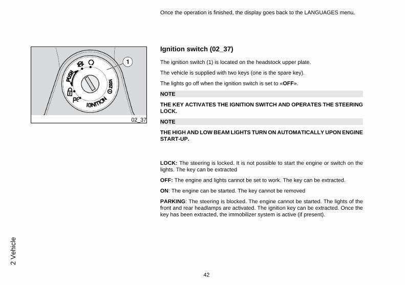
Ignition switch (02_37)
The ignition switch (1) is located on the headstock upper plate.
The vehicle is supplied with two keys (one is the spare key).
The lights go off when the ignition switch is set to «OFF».
NOTE
THE KEY ACTIVATES THE IGNITION SWITCH AND OPERATES THE STEERINGLOCK.
NOTE
THE HIGH AND LOW BEAM LIGHTS TURN ON AUTOMATICALLY UPON ENGINESTART-UP.
LOCK: The steering is locked. It is not possible to start the engine or switch on thelights. The key can be extracted
OFF: The engine and lights cannot be set to work. The key can be extracted.
ON: The engine can be started. The key cannot be removed
PARKING: The steering is blocked. The engine cannot be started. The lights of thefront and rear headlamps are activated. The ignition key can be extracted. Once thekey has been extracted, the immobilizer system is active (if present).
42
2 Ve
hicl
e

02_38
Locking the steering wheel (02_38)
To lock the steering:
• Turn the handlebar completely to the left.
• Turn the key to «OFF».
• Push in the key and turn it anticlockwise (to the left), steer the handlebar slowly untilthe key is set to «LOCK».
• Remove the key.
CAUTION
TO AVOID LOSING CONTROL OF THE VEHICLE, NEVER TURN THE KEY TO"LOCK" WHILE RIDING.
a-PRC setting buttons (02_39, 02_40)
(if applicable)
02_39
These allow the rider to adjust the settings of the different functions of the a-PRCsystem.
43
2 Vehicle

02_40
02_41
Horn button (02_41)
Press it to activate the horn.
44
2 Ve
hicl
e

02_42
Switch direction indicators (02_42)
Move the switch to the left, to indicate a left turn; move the switch to the right to indicatea right turn. Pressing the switch deactivates the turn indicator.
CAUTION
IF THE WARNING LIGHT WITH ARROWS FLASHES QUICKLY, IT MEANS THATONE OR BOTH TURN SIGNALS LIGHT BULBS ARE BURNT OUT.
The turn indicators have a self-cancelling function that implements the following logic.
With the vehicle at a standstill (speed = zero), the turn indicators continue flashingindefinitely.
With the vehicle in motion, the turn indicators self-cancel when one the two followingconditions is met:
• After a time (t) = 40 sec.• After riding 500 m (0.31 mi).
If the vehicle speed reaches zero during this period, the time and distance counts arereset and start again from zero when the vehicle starts moving once again.
Switching on the opposite side turn indicators without pressing the switch in the in-termediate reset position causes both the time and distance counters to reset andrecommence from zero.
45
2 Vehicle

02_43
High/low beam selector (02_43)
Press the light switch to turn on the low beam light; press it again to turn on the highbeam light.
02_44
Passing button (02_44)
Uses the high beam flash in case of danger or emergency.
Releasing the switch deactivates the high beam flash.
46
2 Ve
hicl
e

02_45
Start-up button (02_45)
With the key inserted in the ignition and turned to ON, when the button is pushed thestarter motor will start the engine
AFTER A FEW SECONDS FROM THE ENGINE START-UP, THE START-UP BUT-TON ASSUMES THE MAPPING CHANGE FUNCTION.
02_46
Engine stop switch (02_46)
It acts as an engine cut-off or emergency stop switch.
Press this switch to stop the engine.
System a-PRC (Aprilia Performance Ride Control)
(if applicable)
a-PRC system (Aprilia Performance Ride Control)
Aprilia Performance Ride Control is an engine torque control system that helps im-prove performance and enhance safety for the rider.
47
2 Vehicle

a-PRC consists of four systems:
ATC: Aprilia Traction Control;
AWC: Aprilia Wheelie Control;
ALC: Aprilia Launch Control;
AQS: Aprilia Quick Shift.
WARNING AND INDICATOR LIGHTS, KEY
- Indicator light off: with system activated with vehicle in motion or system activatedafter exceeding 5 Km/h (3.1 mph) after key-on;
- Indicator light continuously lit: with system intentionally deactivated by rider or inthe event of a malfunction causing deactivation;
- Indicator light flashing slowly: with system active after key-on before exceeding5 Km/h (3.1 mph) or in the case of certain malfunctions causing ATC level to be locked("+" and "-" buttons disabled);
- Indicator light flashing quickly: when one of the a-PRC functions (ATC, AWC andALC) is actively invoking traction control.
Aprilia Traction Control
Traction control: a system designed to help the rider control wheelspin.
ATC is a system that monitors and, if necessary, limits rear wheelspin under acceler-ation to increase vehicle stability.
While ATC improves vehicle control, it does not allow the physical handling limits ofthe vehicle to be exceeded. The rider is fully responsible for riding at a suitable speedbased on weather and road conditions, always leaving an appropriate safety margin.
48
2 Ve
hicl
e

Under no circumstances can ATC compensate for any rider error or improper use ofthe throttle.
THE TRACTION CONTROL SYSTEM CANNOT PREVENT FALLS WHILE COR-NERING.
ACCELERATING SUDDENLY WHILE THE VEHICLE IS INCLINED OR WITH THEHANDLEBARS TURNED WILL PUT THE VEHICLE IN AN UNSTABLE STATETHAT IS EXTREMELY DIFFICULT TO RECTIFY.
DO NOT SPEED RECKLESSLY. LIMITS OF GRIP ARE DETERMINED BY LAWSOF PHYSICS WHICH EVEN THE ATC SYSTEM CANNOT OVERCOME.
The ATC system also responds optimally and limits wheelspin during cornering.
This is made possible by the inertia sensor platform, which provides the ECU withprecise information concerning the inclination of the motorcycle.
ATC SYSTEM DEACTIVATED MANUALLY
At key-on and after the initial instrument panel check cycle, if the system is deactiva-ted, the a-PRC indicator light remains lit constantly until the rider activates the systemagain.
ATC SYSTEM ACTIVE
At key-on and after the initial instrument panel check cycle, if the system was activeat the last key-off, the a-PRC indicator light flashes until the vehicle exceeds 5 Km/h(3.1 mph), after which it extinguishes.
If the a-PRC indicator light remains constantly lit, this means that a fault has beendetected and the ATC system has been automatically deactivated.
In this case carry out the following operations:
49
2 Vehicle

- stop the vehicle;
- key OFF-ON;
- reactivate the system manually
- ride over 5 km/h (3.1 mph): the a-PRC indicator light should extinguish;
- ATC system working correctly.
If the 'ATC system deactivated' indication persists:
NOTE
SHOULD THIS OCCUR, CONTACT AN aprilia Official Dealer.
THE ATC SYSTEM ACTS ON THE REAR WHEEL ON THE BASIS OF INFORMA-TION RECEIVED FROM TONE WHEELS INSTALLED ON BOTH WHEELS. AL-WAYS CHECK THAT THE TONE WHEELS ARE CLEAN, AND REGULARLYCHECK THAT THE GAP BETWEEN THE TONE WHEEL AND THE SENSOR ISCONSTANT AROUND THE ENTIRE CIRCUMFERENCE OF THE TONE WHEELITSELF. SHOULD THE WHEELS BE REMOVED AND REFITTED, IT IS VERY IM-PORTANT TO CHECK THAT THE DISTANCE BETWEEN TONE WHEEL ANDSENSOR IS THE ONE SPECIFIED. FOR CHECKING AND ADJUSTMENT, CON-TACT AN Authorised APRILIA Workshop.
NOTE
PROLONGED ROTATION OF THE REAR WHEEL WHILE THE FRONT WHEEL ISSTATIONARY (BURNOUT, MOTORCYCLE ON CENTRE STAND ETC.) MAYCAUSE THE SYSTEM TO AUTOMATICALLY DEACTIVATE AND THE a-PRC IN-DICATOR LIGHT TO LIGHT CONSTANTLY.
TO REACTIVATE, TURN THE IGNITION SWITCH OFF AND THEN ON AGAIN ANDSELECT THE REQUIRED SETTING.
50
2 Ve
hicl
e

NOTE
a-PRC SYSTEM SENSORS, WITH HIGH PRECISION OF READING THE TONEWHEELS, CAN GENERATE, WITH MOTORCYCLE AT STANDSTILL AND RUN-NING ENGINE, A km/h (mi) SPEED INDICATION IN THE DIGITAL DISPLAY.
SUCH PERFORMANCE IS NORMAL AND DOES NOT CAUSE MALFUNCTIONINGOF THE a-PRC SYSTEM.
CharacteristicDistance between tone wheel and front sensor
0.3 - 2.00 mm (0.012 - 0.079 in)
Distance between tone wheel and rear sensor
0.3 - 2.00 mm (0.012 - 0.079 in)
To activate the system, press and hold the "+" setting button, the value "1" is shownon the display.
When the ATC system is activated with the vehicle at a standstill, the a-PRC indicatorlight flashes until the vehicle reaches a speed of 5 Km/h (3.1 mph).
Press the "+" and "-" buttons briefly to increase or decrease the ATC level setting from"1" (minimum system intervention) to "8" (maximum system intervention).
NOTE
THIS IS ALSO POSSIBLE WITH THE MOTORCYCLE IN MOTION.
NOTE
EACH TIME THE SET VALUE IS MODIFIED, THE NUMERICAL SYMBOL FLASH-ES FOR APPROXIMATELY 2 SECONDS BEFORE THE NEW SETTING IS CON-FIRMED.
CAUTION
TO GAIN FAMILIARITY WITH THE ATC SYSTEM, PREFERABLY USE LEVEL "8"TO START WITH, THEN TRY THE OTHER LEVELS TO IDENTIFY WHICH ARE
51
2 Vehicle

THE BEST SUITED TO YOUR RIDING STYLE AND FOR DIFFERENT ROAD ANDWEATHER CONDITIONS.
LEVEL "1" IS RECOMMENDED FOR USE BY EXPERT RIDERS IN IDEAL ROADSURFACE CONDITIONS.
ALL OTHER LEVELS ARE INTERMEDIATE SETTINGS BETWEEN LEVEL "1"AND LEVEL "8".
To deactivate the system, select the minimum level "1" then press and hold the "-"setting button.
The a-PRC indicator light is constantly lit.
NOTE
THIS IS ALSO POSSIBLE WITH THE MOTORCYCLE IN MOTION.
NOTE
WHEN THE BATTERY IS CONNECTED FOR THE FIRST TIME, THE a-PRC INDI-CATOR LIGHT IS CONSTANTLY LIT (SYSTEM NOT ACTIVE)
NOTE
IF THE IGNITION SWITCH IS TURNED OFF AND LEFT OFF FOR OVER 30 SEC-ONDS, AT THE NEXT KEY-ON, THE ATC SYSTEM MAINTAINS THE PREVIOUS-LY SELECTED SETTINGS.
Aprilia Wheelie Control
Wheelie control: a system designed to help the rider control wheeling by reducingtorque to gently lower the front wheel to the ground.
CAUTION
WITH AWC DEACTIVATED AND ATC ACTIVATED:
52
2 Ve
hicl
e

- WHEELING IS LIMITED TO A MAXIMUM DURATION OF 30 SECONDS. AFTERTHIS PERIOD, THE SYSTEM BRINGS THE FRONT WHEEL BACK TO THEGROUND.
- WHEELING IS NOT PERMITTED IF THE MOTORCYCLE IS BANKED BY +/- 25°RELATIVE TO THE VERTICAL. IF THIS ANGLE IS EXCEEDED, THE SYSTEMRETURNS THE FRONT WHEEL TO THE GROUND.
TABLE OF RECOMMENDED SETTINGS
Engine map ATC AWC Road surface
Road 7 / 8 3 Wet road or poor grip conditions
Sport 4 / 6 2 Dry road, medium grip conditions
Track 1 / 3 - / 1 Dry road or track, excellent grip conditions
NOTE
THE TABLE IS ONLY INTENDED AS A GUIDELINE FOR SETTING THE LEVELSOF EACH CONTROL SYSTEM. EACH RIDER MAY PERSONALISE THE LEVELSTO THEIR OWN PREFERENCE IN ACCORDANCE WITH ABILITY, RIDING STYLEAND ROAD CONDITIONS. FOR MORE INFORMATION ON LEVEL SETTINGS,SEE THE RELATIVE PARAGRAPHS FOR EACH INDIVIDUAL FUNCTION.
Aprilia Launch Control
Launch control: a system designed to help the rider optimise acceleration duringstanding starts.
53
2 Vehicle
CAUTION
ALC MUST BE USED WITH EXTREME PRUDENCE AS THERE IS NO FUNCTIONTO PREVENT THE MOTORCYCLE FROM FLIPPING IN ANY OF THE THREEPOSSIBLE LEVELS.
THE SYSTEM IS FOR EXPERT RIDERS AND EXCLUSIVELY FOR TRACK USE.
RELEASE THE CLUTCH PROGRESSIVELY TO PREVENT EXCESS SLIPPAGE,WHICH COULD DAMAGE THE MECHANICALS OF THE VEHICLE.
ALC launch control is a specific functioning scenario for the traction control systemwhich takes into consideration the fact that initial speed is zero. Once the LAUNCHcontrol function is activated and the throttle is opened completely, the engine speedincreases to and is maintained at approximately 9,500 rpm, irrespective of the levelset. The LAUNCH function is automatically deactivated in the event of any of the threefollowing situations:
• A gear higher than second is selected;• Vehicle speed exceeds 145 Km/h (90.10 mph).
To activate ALC in the level selected previously from the menu, with the vehicle sta-tionary, simultaneously press and hold "+" and "-" for at least 3 seconds, until themessage "LAUNCH" (in ROAD display mode) or "L" (in RACE display mode) is shownon the digital display.
When ALC is activated, the ATC and AWC systems are automatically deactivated andremain so until the ALC function is exited ALC (message cleared from digital display).Once the ALC function is exited, the ATC and AWC systems resume operation withthe settings selected previously.
CAUTION
DURING THE INITIAL STAGE OF ALC FUNCTION (DURING CLUTCH RELEASE),THE SYSTEM HELPS THE RIDER KEEP THE FRONT WHEEL AS CLOSE TO THEGROUND AS POSSIBLE.
DURING THE SECOND STAGE OF ALC FUNCTION (WITH THE CLUTCH LEVERCOMPLETELY RELEASED), THE OBJECTIVE OF THE SYSTEM IS TO HELP THERIDER MAXIMISE VEHICLE ACCELERATION IN RELATION TO THE ALC LEVELSELECTED. DURING THE SECOND STAGE OF OPERATION, THE SYSTEM AL-
54
2 Ve
hicl
e

LOWS THE FRONT WHEEL TO LIFT FROM THE GROUND TO MAXIMISE AC-CELERATION.
AWC and/or ALC can only be activated if the ATC system is on. This means thatneither the wheelie control function nor launch control can be selected unless thetraction control is on. The three systems can therefore be set independently of oneanother and can function simultaneously.
Aprilia Quick Shift
A system that enables upshifts without using the clutch and without changing thethrottle position.
This system uses the gear shift signal from the gear lever to perform quicker gearchanges with a smaller drop in engine speed than with a conventional gear shift.
The system is only active above an engine speed of approximately 4000 rpm.
CAUTION
THE CLUTCH MUST BE USED FOR UPSHIFTS AT ENGINE SPEEDS BELOW4000 RPM.
CAUTION
THE SYSTEM IS ACTIVE ONLY DURING UPSHIFTS, WITH THE THROTTLEOPEN.
THE SYSTEM IS NOT ACTIVE DURING DOWNSHIFTS.
55
2 Vehicle

02_47
Immobilizer system operation (02_47)
For enhanced theft protection, the vehicle is equipped with an electronic immobilizersystem that is activated automatically when the ignition key is removed.
Keep the second key in a safe place since it is not possible to make a copy if it getslost.
This would imply replacing numerous parts of the vehicle (besides the locks).
Each key in the grip has an electronic device - transponder - which modulates theradio frequency signal emitted by a special aerial inside the switch when the vehicleis started.
The modulated signal is the "password" by which the appropriate central unit recog-nises the key and only after this occurs, it allows the engine start-up.
CAUTION
THE IMMOBILIZER SYSTEM CAN MEMORISE UP TO FOUR KEYS.
DATA STORAGE OPERATION CAN ONLY BE PERFORMED AT AN Aprilia offi-cial DEALER.
DATA STORAGE PROCEDURE CANCELS THE EXISTING CODES. THEREFORE,IF A CUSTOMER WANTS TO PROGRAM SOME NEW KEYS, S/HE SHOULD GOTO THE DEALER TAKING ALL THE KEYS S/HE WANTS TO ENABLE.
56
2 Ve
hicl
e

02_48
Opening the saddle (02_48, 02_49, 02_50, 02_51, 02_52, 02_53)
PASSENGER SEAT REMOVAL
• Turn the key clockwise.
02_49
• Remove the passenger seat by raising first the end.
02_50
• Complete removal by raising and sliding the passenger seat.
57
2 Vehicle

02_51
02_52
RIDER SADDLE REMOVAL
• Using the Allen key located under the tail fairing / passenger saddle, unscrewand remove the two screws fastening the saddle and remove the saddle fromthe vehicle.
02_53
Refitting
• Carry out the procedure described above in reverse order.• After refitting and fastening the saddle, place the Allen key in the relative seat
under the passenger seat.
NOTE
AFTER REFITTING THE PASSENGER SEAT, PAY SPECIAL ATTENTION TOCORRECT AND COMPLETE POSITIONING OF THE END.
58
2 Ve
hicl
e

CAUTION
BEFORE LOWERING AND LOCKING THE SADDLE, CHECK THAT THE IGNITIONKEY HAS NOT BEEN LEFT THE IGNITION KEY IN THE GLOVEBOX /TOOL KIT.
02_54
Glove/tool kit compartment (02_54)
• The saddle must be removed in order to access the glovebox / toolkit.• The tool kit is hooked to the bottom of the saddle.
02_55
Identification (02_55)
Write down the chassis and engine number in the specific space in this booklet. Thechassis number is handy when purchasing spare parts.
CAUTION
THE MODIFICATION OF THE IDENTIFICATION CODES IS A SERIOUS PUNISH-ABLE CRIME. HOWEVER, THE LIMITED WARRANTY FOR NEW VEHICLES WILLBE VOID IF THE VEHICLE IDENTIFICATION NUMBER (VIN) HAS BEEN MODI-FIED OR NOT PROMPTLY DETERMINED.
CHASSIS NUMBER
59
2 Vehicle

The chassis number is stamped on the right side of the headstock.
Chassis No. ....................
ENGINE NUMBER
The engine number is printed on the base of the engine crankcase, left hand side.
Engine No. ....................
60
2 Ve
hicl
e

Tuono V4
Chap. 03Use
61

Checks (03_01)
CAUTION
BEFORE RIDING, ALWAYS PERFORM A PRELIMINARY CHECK OF THE VEHI-CLE TO ENSURE CORRECT AND SAFE OPERATION. FAILURE TO DO SO MAYLEAD TO SERIOUS PERSONAL INJURY OR DAMAGE TO THE VEHICLE. DONOT HESITATE TO CONTACT AN OFFICIAL Aprilia DEALER IF YOU DO NOTUNDERSTAND HOW SOME CONTROLS WORK OR IF A MALFUNCTION IS DE-TECTED OR SUSPECTED. CHECKING TAKES VERY LITTLE TIME BUT CON-SIDERABLY INCREASES SAFETY.
03_01
This vehicle has been programmed to indicate in real time any operation failure storedin the electronic control unit memory.
Every time the ignition switch is turned to "KEY ON", the alarm LED warning light turnson for about three seconds on the instrument panel.
PRE-RIDE CHECKS
Front and rear disc brake Check for proper operation. Checkbrake lever empty travel and brakefluid level. Check for leaks. Check
62
3 U
se

brake pads for wear. If necessarytop-up with brake fluid.
Throttle grip Check that the throttle functionssmoothly and can be fully openedand closed in all steering positions.Adjust and/or lubricate ifnecessary.
Engine oil Check and/or top-up as required.
Wheels/ tyres Check that tyres are in goodconditions. Check inflationpressure, tyre wear and potentialdamage.
Remove any possible strangebody that might be stuck in thetread design.
Brake levers Check they function smoothly.
Lubricate the joints and adjust thetravel if necessary.
Clutch lever Check correct operation and emptytravel. Check the condition of thecable on the handlebar and on theengine. The cable must bereplaced if it shows any signs offraying. Lubricate the joints ifnecessary.
Steering Check that rotation is free andsmooth to the end of the stroke onboth sides, with no clearance orslack.
63
3 Use

Side stand Check that it slides smoothly andthat it snaps back to its rest positionupon spring tension. Lubricatecouplings and joints if necessary.
Check that the side stand safetyswitch operates correctly.
Clamping elements Check that the clamping elementsare not loose.
Adjust or tighten them as required.
Fuel tank Check the coolant level and refill ifnecessary.
Check the circuit for leaks orobstructions.
Check that the tank cap closescorrectly.
Engine stop switch (ON - OFF) Check function.
Lights, warning lights, horn, rearstop light switch and electricaldevices
Check function of horn and lights.Replace bulbs or repair any faultsnoted.
Tone wheels Check that the tone wheels areperfectly clean and in goodconditions.
64
3 U
se

03_02
Refuelling (03_02)
To refuel:
• Lift the cover (1).• Introduce the key (2) in the fuel tank cap lock (3).• Turn the key clockwise, pull and open the fuel tank lid.
CharacteristicFuel capacity (reserve included)
17 l (3.74 UK gal)
Fuel tank reserve
3.6 l (0.79 UK gal)
• Refuel.
CAUTION
DO NOT ADD ADDITIVES OR ANY OTHER SUBSTANCES TO THE FUEL.
WHEN USING A FUNNEL OR ANY OTHER ELEMENT, MAKE SURE IT IS PER-FECTLY CLEAN.
DO NOT FILL THE TANK UP TO THE RIM; FUEL MAXIMUM LEVEL MUST AL-WAYS BE BELOW THE LOWER EDGE OF THE FILLER NECK (SEE FIGURE).
after refuelling:
• The fuel cap may only be refitted with the key (2) inserted.
65
3 Use

• Once the key (2) is inserted, press the cap to close it again.• Remove the key (2).• Close the cover (1).
MAKE SURE THE CAP IS TIGHTLY CLOSED.
03_03
Rear shock absorbers adjustment (03_03)
The rear suspension consists of a spring-shock absorber unit linked to the frame viauniball joints and to the swingarm via a linkage system.
To adjust the rear shock absorbers, the following adjustments can be performed: Re-bound damping, adjusting with the knurled hand grip (1); compression damping byadjusting the thumbscrew with the knob (2); Spring preload by adjusting the ring nut(3) blocked in its seat by the lock ring nut (4).
NOTE
THE VEHICLE HAS A HEIGHT ADJUSTABLE SUSPENSION. FOR USE ON THETRACK PLEASE OBSERVE THE VALUES RECOMMENDED FOR USE ON THEROAD.
CAUTION
CARRY OUT MAINTENANCE OPERATIONS AT HALF THE INTERVALS SPECI-FIED IF THE VEHICLE IS USED IN PARTICULAR RAINY OR DUSTY CONDI-TIONS, OFF ROAD OR FOR TRACK USE.
REAR SHOCK ABSORBER STANDARD SETTING IS ADJUSTED TO MEETSPORTING RIDING.
HOWEVER, THIS SET CAN BE ADJUSTED TO SPECIFIC NEEDS ACCORDINGTO VEHICLE USE.
66
3 U
se

RACING TRACK SETTINGS MUST BE DONE ONLY FOR OFFICIAL COMPETI-TIONS OR SPORTS EVENTS WHICH ARE, IN ALL CASES, AWAY FROM NOR-MAL ROAD TRAFFIC AND WITH THE AUTHORISATION OF THE RELEVANTAUTHORITIES.
IT IS STRICTLY FORBIDDEN TO RIDE A VEHICLE SET FOR RACING ON ROADSAND MOTORWAYS.
TO COUNT THE NUMBER OF RELEASES AND/OR REVOLUTIONS OF ADJUST-MENT SETTINGS (1 - 2) ALWAYS START FROM THE MOST RIGID SETTING(WHOLE CLOCKWISE ROTATION OF THE SETTING).
DO NOT FORCE THE SET SCREWS (1 - 2) TO TURN BEYOND THE END OF THESTROKE ON BOTH SIDES SO AS NOT DAMAGE THEM.
• Using the specific spanner, unscrew the locking ring nut (4).• Operate on the adjusting ring nut (3) to adjust the spring preloading (A).• Once the adjustment is done, screw the ring nut (4).• Turn the (1) screw to adjust the shock absorber hydraulic rebound damping.• Turn the knob (2) to adjust the shock absorber hydraulic compression damp-
ing.
SET SPRING PRELOADING AND SHOCK ABSORBER REBOUND DAMPING AC-CORDING TO THE VEHICLE USE CONDITIONS.
IF THE SPRING PRELOADING IS INCREASED, IT IS NECESSARY TO INCREASETHE REBOUND DAMPING ACCORDINGLY TO AVOID SUDDEN JERKS WHENRIDING.
67
3 Use

CAUTION
ALWAYS OBSERVE THE RECOMMENDED ADJUSTMENT RANGE.
CAUTION
FOR THE CORRECT SETTING PARAMETERS, READ THE PARAGRAPH "SET-TING THE REAR SHOCK ABSORBER" CAREFULLY.
Take your vehicle to an official Aprilia dealer, if necessary.
TRY RIDING THE VEHICLE ON THE STREET UNTIL THE OPTIMUM ADJUST-MENT IS OBTAINED.
03_04
Rear shock absorbers setting (03_04)
SPORT SETTINGS MAY BE USED ONLY FOR OFFICIAL COMPETITIONS TO BECARRIED OUT ON TRACKS, AWAY FROM NORMAL ROAD TRAFFIC AND WITHTHE AUTHORISATION OF THE RELEVANT AUTHORITIES.
68
3 U
se

REAR SHOCK ABSORBER - STANDARD ADJUSTMENT(FOR USE ON ROAD)
Length of (preloaded) spring (A) 145 mm (5.71 in)
Rebound adjustment, ring nut (1) open (**) 20 clicks from fully closed(*)
Compression adjustment, knob (2) open (**) 2 clicks from fully closed(*)
REAR SHOCK ABSORBER - RACING ADJUSTMENT RANGE(ONLY ON THE RACING TRACK)
Length of (preloaded) spring (A) 143.5 mm (5.65 in)
Rebound adjustment, ring nut (1) open (**) 9 -12 clicks from fullyclosed (*)
Compression adjustment, knob (2) open (**) 0.5-1 turn from fullyclosed (*)
(*) = clockwise
(**) = anticlockwise
69
3 Use

03_05
Front fork adjustment (03_05)
• Operating the front brake lever, press the handlebar repeatedly to send thefork fully down. The stroke should be soft and there should be no oil markson the stems.
• Check the tightening of all the elements and the correct operation of the frontand rear suspension joints.
CAUTION
PLEASE CONTACT AN Official Aprilia Dealer TO HAVE THE FRONT FORK OILCHANGED AND ITS OIL SEALS REPLACED.
The front suspension consists of a hydraulic fork connected to the headstock bymeans of two plates.
To adjust the settings for this vehicle, each fork is equipped with an upper adjustmentscrew (1) to set the rebound damping; an upper nut (3) to adjust the spring preloadingand a lower adjustment screw (2) to modify the compression damping.
TO PREVENT DAMAGE, DO NOT FORCE THE ADJUSTER (1-2) ROTATION BE-YOND THE RESPECTIVE END OF TRAVEL IN EITHER DIRECTION. SET BOTHSTEMS WITH THE SAME SPRING PRELOAD AND DAMPING TOLERANCES:RIDING THE VEHICLE WITH A DIFFERENT ADJUSTMENT FOR THE TWOSTEMS REDUCES ITS STABILITY. IF YOU INCREASE SPRING PRELOAD, YOUALSO NEED TO INCREASE REBOUND DAMPING TO PREVENT SUDDEN JERKSWHILE RIDING.
Standard front fork setting is adjusted to suit most high and low speed riding condi-tions, whether the vehicle is partially or fully loaded.
However, the setting can be modified for specific needs according to vehicle use.
70
3 U
se

RACING TRACK SETTINGS MUST BE DONE ONLY FOR OFFICIAL COMPETI-TIONS OR SPORTS EVENTS WHICH ARE, IN ALL CASES, AWAY FROM NOR-MAL ROAD TRAFFIC AND WITH THE AUTHORISATION OF THE RELEVANTAUTHORITIES.
IT IS STRICTLY FORBIDDEN TO RIDE A VEHICLE SET FOR RACING ON ROADSAND MOTORWAYS.
CAUTION
FOR THE CORRECT SETTING PARAMETERS, READ THE PARAGRAPH "SET-TING THE FRONT FORK" CAREFULLY.
Take your vehicle to an official Aprilia dealer, if necessary.
03_06
Front fork setting (03_06, 03_07, 03_08)
TO COUNT THE CLICKS AND/OR TURNS OF SET SCREWS (1 - 2 - 3) ALWAYSSTART FROM THE MOST RIGID SETTING (SET SCREW FULLY CLOCKWISE).
71
3 Use

03_07
03_08
FRONT FORK - STANDARD ADJUSTMENT (FOR USE ONROAD)
Rebound damping adjustment,screw (1)
Unscrew (**) 10 clicks from fullyclosed (*)
Compression dampingadjustment, screw (2)
Unscrew (**) 6 clicks from fullyclosed (*)
Spring preloading, nut (3) screw (*) 5 turns from fully open (**)
72
3 U
se

Stems (A) (***) protrusion from topplate (excluding cover)
2 notches/ 8 mm (2 notches/0.32in)
FRONT FORK - RACING ADJUSTMENT RANGE (ONLY TRACKUSE)
Rebound damping adjustment,screw (1)
Unscrew (**) 7-10 clicks (*) fromfully closed
Compression dampingadjustment, screw (2)
Unscrew (**) 4-6 clicks (*) from fullyclosed
Spring preloading, nut (3) Screw (*) 4-6 turns (**) from fullyopen
Stems (A) (***) protrusion from topplate (excluding cover)
2-3 notches/ 8-12 mm (2-3notches/0.32-0.47 in)
(*) - Clockwise
(**) - Anticlockwise
(***) - this type of adjustment may only be made by an aprilia Official Dealer.
Steering shock absorber adjustment (03_09)
(if applicable)
73
3 Use

03_09
The motorcycle has a non adjustable steering damper. No adjustment can be made.
03_10
Justering af greb til forbremse (03_10)
The distance between the end of the lever (1) and the hand grip (2) may be adjustedwith the set screw (3).
• Push the control lever (1) forward and turn the set screw (3) until the lever(1) is at the desired distance.
• Turn the adjuster screw anticlockwise to bring the lever (1) closer to the handgrip (2).
74
3 U
se

03_11
03_12
Clutch lever adjustment (03_11, 03_12)
The clutch lever clearance (1) may be adjusted with the adjuster screw (3).
• Turn the adjuster screw (3) forward to increase clutch lever clearance (1) andcheck lever function while using the hand grip (2) as you would when ridingthe vehicle.
• Check that clearance is between 1 and 3 mm (0.039 e 0.12 in).
CAUTION
WHENEVER MODIFYING THE CLUTCH LEVER ANGLE, ALWAYS ENSURETHAT THERE IS NO INTERFERENCE AT ALL BETWEEN THE LEVER AND THE"-" BUTTON WHEN THE LEVER IS PULLED COMPLETELY. FAILURE TO DO SOMAY RESULT IN a-PRC MALFUNCTIONS.
Running in
Running the engine in correctly is essential for ensuring engine longevity and func-tionality. Twisty roads and gradients are ideal for running in the engine, brakes andsuspension effectively. Vary your riding speed during the running in period. This en-sures that components operate in "loaded" conditions and then "unloaded" conditions,allowing the engine components to cool.
75
3 Use

CAUTION
THE FULL PERFORMANCE OF THE VEHICLE IS ONLY AVAILABLE AFTER THESERVICE AT THE END OF THE RUNNING IN PERIOD.
Follow the guidelines detailed below:
• Do not twist the throttle grip abruptly and completely when the engine isworking at a low revs, either during or after run-in.
• During the first 100 Km (62 miles) use the brakes gently, avoiding sudden orprolonged braking. That is to permit the adequate adjustment of the pad fric-tion material to the brake discs.
• It is recommended, during the first 1000 km (621 mi), not to exceed 7500 rpmand 9500 rpm up 2000 km (1243 mi).
AFTER THE SPECIFIED MILEAGE, TAKE YOUR VEHICLE TO AN Official ApriliaDealer FOR THE CHECKS INDICATED IN THE "PERIODICAL MAINTENANCE"TABLE IN THE SCHEDULED MAINTENANCE SECTION TO AVOID INJURINGYOURSELF, OTHERS AND /OR DAMAGING THE VEHICLE.
Starting up the engine (03_13, 03_14, 03_15, 03_16, 03_17)
This vehicle is extremely powerful and must be used carefully and driven withcaution and respect for its power and potential.
Do not carry objects in the top fairing (between the handlebar and the instrumentpanel) so that the handlebar can turn freely and the instrument panel is visibleat all times.
76
3 U
se

EXHAUST FUMES CONTAIN CARBON MONOXIDE, AN EXTREMELY HARMFULSUBSTANCE IF INHALED.
NEVER START THE ENGINE IN A CLOSED OR INSUFFICIENTLY VENTILATEDSPACE.
FAILURE TO OBSERVE THIS WARNING COULD LEAD TO UNCONSCIOUSNESSAND EVEN DEATH DUE TO SUFFOCATION.
CAUTION
WITH THE SIDE STAND LOWERED, THE ENGINE MAY ONLY BE STARTED WITHTHE GEARBOX IN NEUTRAL. IF YOU ATTEMPT TO ENGAGE A GEAR IN THISCONDITION THE ENGINE WILL STOP.
WITH THE SIDE STAND RETRACTED, THE ENGINE MAY BE STARTED WITHTHE GEARBOX IN NEUTRAL OR WITH GEAR ENGAGED AND THE CLUTCHLEVER PRESSED.
03_13
• Get on the motorcycle, assuming the correct driving posture.• Make sure that the side stand has been fully retracted.• Operate the front or rear brake (or both).• Operate the clutch lever (7) and make sure that the transmission (8) is in
neutral. If the transmission is in neutral, the green coloured light "N" (9) willturn on.
• Press the engine stop switch (1) to "RUN", turn the ignition key (3) to "ON".• Press the starter button (2) once only.
At this stage:
• The starting screen page will be shown on the multifunction display for 2seconds.
• All warning lights (4) and the backlighting will turn on for 2 seconds on theinstrument panel.
77
3 Use

03_14
03_15
03_16
• The rpm indicator (5) will go to the end of the scale for 3 seconds, then it willreturn to the minimum value.
• With the engine operating normally, the number of rpms at which the engineis operating will be displayed instantaneously.
IF THE LOW FUEL WARNING LIGHT ON THE INSTRUMENT PANEL TURNS ON,REFUEL THE VEHICLE AT ONCE.
INTENSE USE/ON THE TRACK IN RESERVE CAN DAMAGE THE ENGINE.
THE OVERREVVING THRESHOLD IN NEW VEHICLES IS SET TO 6000 RPM.RAISE THE THRESHOLD GRADUALLY AS YOU BECOME FAMILIAR WITH THEVEHICLE AND RUNNING IN HAS BEEN COMPLETED.
78
3 U
se

03_17
AFTER A FEW SECONDS FROM THE ENGINE START-UP, THE START-UP BUT-TON ASSUMES THE MAPPING CHANGE FUNCTION.
IF THE ENGINE OIL PRESSURE ICON IS DISPLAYED AND THE GENERALWARNING LIGHT IS ON, THE OIL PRESSURE IN THE CIRCUIT IS TOO LOW.
DO NOT SET OFF SUDDENLY WHEN THE ENGINE IS COLD. RIDE AT LOWSPEED FOR SEVERAL KILOMETRES. THIS WILL ALLOW THE ENGINE TOWARM UP AND REDUCE POLLUTING EMISSIONS AND FUEL CONSUMPTION.
IF THE WORD "SERVICE" OR "URGENT SERVICE" IS SHOWN ON THE (MUL-TIFUNCTION) DISPLAY DURING REGULAR ENGINE OPERATION, IT MEANSTHERE IS A MALFUNCTION.
Moving off / riding (03_18, 03_19, 03_20, 03_21)
CAUTION
WHEN TRAVELLING WITHOUT PASSENGERS, MAKE SURE THE PASSENGERFOOTRESTS ARE FOLDED UP.
79
3 Use

CAUTION
PASSENGERS MUST BE SUITABLY INSTRUCTED ON HOW TO BEHAVE TOPREVENT DANGEROUS SITUATIONS WHEN RIDING.
BEFORE SETTING OFF, MAKE SURE THE STAND HAS BEEN COMPLETELYRETRACTED TO ITS POSITION.
03_18
To start:
• Turn on the engine.• Adjust the inclination of the rear-view mirrors to ensure proper visibility.
CAUTION
WITH THE VEHICLE AT A STANDSTILL, PRACTICE USING THE REAR-VIEWMIRRORS. THE MIRRORS ARE CONVEX, SO OBJECTS MAY SEEM FARTHERAWAY THAN THEY REALLY ARE. THESE MIRRORS OFFER A WIDE-ANGLEVIEW AND ONLY EXPERIENCE HELPS YOU JUDGE THE DISTANCE SEPARAT-ING YOU AND THE VEHICLE BEHIND.
03_19
• With throttle grip (2) closed (Pos. A) and engine at idle, operate the clutchlever (3).
• Push the gearbox lever (4) downward to select the first gear.• Release the clutch lever (activated during start-up).
CAUTION
WHEN TURNING OFF THE VEHICLE, DO NOT RELEASE THE CLUTCH TOOQUICKLY OR SUDDENLY, AS THIS COULD CAUSE THE ENGINE TO STOP ORTHE VEHICLE TO REAR UP ON THE BACK WHEEL. DO NOT ACCELERATESUDDENLY WHEN RELEASING THE CLUTCH FOR THE SAME REASON.
80
3 U
se

03_20
• Slowly release the clutch lever (3) and at the same time accelerate by slightlytwisting the throttle grip (2) (Pos. B).
The vehicle starts moving forward.
• For the first kilometres travelled, limit the speed in order to warm up the en-gine.
NOTE
THE VEHICLE IS EQUIPPED WITH AN RPM LIMITER THAT IS PART OF THE"RIDE-BY-WIRE" INJECTION SYSTEM.
• Accelerate gradually by twisting the throttle grip (2) (Pos. B) without exceed-ing the recommended rpm.
RIDE IN THE CORRECT GEAR AND SPEED FOR THE CONDITIONS.DO NOT OPERATE THE ENGINE AT A TOO LOW RPM LEVEL.
• Release the throttle grip (2) (Pos. A), operate the clutch lever (3), lift thegearshift lever (4), release the clutch lever (3) and accelerate.
• Repeat the last two operations and engage a higher gear.
IF THE ENGINE OIL PRESSURE ICON IS DISPLAYED DURING REGULAR EN-GINE OPERATION, IT MEANS THAT THE ENGINE OIL PRESSURE IN THE CIR-CUIT IS TOO LOW.
IF THIS OCCURS, STOP THE ENGINE AND CONTACT AN Aprilia Official Dealer.
IT IS SUGGESTED TO DOWNSHIFT FROM A HIGHER GEAR TO A LOWER GEAR:
81
3 Use

• When riding downhill and when braking, in order to increase the brakingpower by using engine compression.
• When going uphill, when the engaged gear does not suit the speed (highgear, moderate speed) and the number of engine revs falls.
CAUTION
DOWNSHIFT ONE GEAR AT A TIME; WHEN SHIFTING TO A LOWER GEAR,DOWNSHIFTING MORE THAN ONE GEAR AT A TIME COULD OVERREV THEENGINE; THAT IS, THE MAXIMUM RPM VALUE PERMITTED FOR THE ENGINECOULD BE EXCEEDED.
NOTE
THE VEHICLE HAS AN ANTI-SLIPPER CLUTCH THAT IS ABLE TO PREVENTTHE WHEEL LOCKING WHEN DOWNSHIFTING, ANY POSSIBLE PULSINGS ONTHE LEVER ARE A SIGN THAT THE SYSTEM IS WORKING PROPERLY.
03_21
• Release the hand grip (2) (Pos.A).• If necessary, pull the brake levers gently and reduce speed.• Operate the clutch lever (3) and lower the gearshift lever (4) to engage a
lower gear.• Release the brake levers when it is operated.• Release the clutch lever (3) and accelerate moderately.
CAUTION
STOP THE VEHICLE MAINLY USING THE FRONT BRAKE. USE THE REARBRAKE TO BALANCE THE BRAKING ONLY AND IN ANY CASE TOGETHERWITH THE FRONT BRAKE.
IF THE COOLANT TEMPERATURE SHOWN ON THE MULTIFUNCTIONAL DIGI-TAL DISPLAY IS HIGHER THAN 115°C (239°F), STOP THE VEHICLE AND LETTHE ENGINE RUN AT 3000 rpm FOR ABOUT TWO MINUTES SO THAT THE
82
3 U
se

COOLANT FLOWS REGULARLY IN THE SYSTEM; THEN SET THE ENGINESTOP SWITCH TO "OFF" AND CHECK THE COOLANT LEVEL.
IF THE TEMPERATURE INDICATION CONTINUES FLASHING AFTER CHECK-ING THE COOLANT LEVEL, CONTACT AN Official Aprilia Dealer.
DO TURN THE IGNITION KEY TO "KEY OFF", BECAUSE THE COOLING FANSWOULD STOP REGARDLESS OF THE COOLANT TEMPERATURE, WHICHWOULD CAUSE A FURTHER TEMPERATURE RISE.
IN MANY CASES THE ENGINE WILL CONTINUE TO OPERATE WITH LIMITEDPERFORMANCE; IMMEDIATELY CONTACT AN Official Aprilia Dealer.
IN ORDER TO AVOID CLUTCH OVERHEATING, SHUT THE ENGINE OFF ASSOON AS POSSIBLE ONCE THE VEHICLE HAS STOPPED AND AT THE SAMETIME THE GEAR IS ENGAGED AND THE CLUTCH LEVER OPERATED.
ACTIVATING ONLY THE FRONT BRAKE OR THE REAR BRAKE SIGNIFICANTLYREDUCES THE BRAKING FORCE OF THE VEHICLE AND A WHEEL COULD BE-COME LOCKED WITH A RESULTING LOSS OF GRIP.
WHEN STOPPING UPHILL, DECELERATE COMPLETELY AND ONLY USE THEBRAKES TO MAINTAIN THE VEHICLE IN THE STOPPED POSITION.
USING THE ENGINE TO KEEP THE MOTORCYCLE STOPPED COULD CAUSETHE CLUTCH TO OVERHEAT. BRAKING CONTINUOUSLY WHEN DRIVINGDOWNHILL COULD CAUSE THE BRAKE PADS TO OVERHEAT, WHICH RE-DUCES BRAKING AND LIMITS BRAKING POWER.
IT IS RECOMMENDED TO USE THE ENGINE COMPRESSION, DOWNSHIFTINGAND USING BOTH BRAKES INTERMITTENTLY.
WHEN DRIVING DOWNHILL, NEVER RIDE WITH THE ENGINE TURNED OFF.
WHEN RIDING ON WET SURFACES OR SURFACES WITH POOR GRIP (SNOW,ICE, MUD, ETC.) USE MODERATE SPEED, AVOID SUDDEN BRAKING OR MA-NOEUVRES THAT MAY CAUSE TO A LOSS OF TRACTION AND POSSIBLY TOA FALL OR CRASH.
83
3 Use

03_22
Stopping the engine (03_22)
• Release the throttle grip (1) (Pos. A), brake gradually and at the same time"downshift" gears to slow down.
Once the speed is reduced, before stopping the vehicle:
• Operate the clutch lever (2) so that engine does not shut off.When the vehicle is at a standstill:
• Set the gearshift lever in neutral (green "N" indicator light lit).• Release the clutch lever.• While at a temporary halt, keep at least one of the vehicle brakes held.
CAUTION
WHENEVER POSSIBLE, AVOID ROUGH BRAKING, SUDDEN DECELERATIONAND BRAKING IN EXCESS.
Parking
It is very important to select an adequate parking spot, in compliance with road signalsand the guidelines described below.
CAUTION
PARK ON SAFE AND LEVEL GROUND TO PREVENT THE VEHICLE FROM FALL-ING.
DO NOT LEAN THE VEHICLE AGAINST A WALL OR LAY IT ON THE GROUND.
MAKE SURE THE VEHICLE AND SPECIALLY ITS HOT PARTS DO NOT POSEANY RISK TO PEOPLE OR CHILDREN. DO NOT LEAVE YOUR VEHICLE UNAT-TENDED WITH THE ENGINE ON OR THE KEY IN THE IGNITION SWITCH.
84
3 U
se

CAUTION
IF THE VEHICLE FALLS OR IS ON A STEEP INCLINE FUEL CAN LEAK.
FUEL USED TO DRIVE INTERNAL COMBUSTION ENGINES IS HIGHLY FLAM-MABLE AND CAN BECOME EXPLOSIVE UNDER CERTAIN CONDITIONS.
DO NOT REST THE RIDER OR PASSENGER WEIGHT ON THE SIDE STAND.
Catalytic silencer
The vehicle has a silencer with a "platinum - palladium - rhodium three-way" metalcatalytic converter.
This device oxidises the CO (carbon monoxide) producing carbon dioxide, and theUHC (unburned hydrocarbons) producing water vapour and reduces NOX (nitrogenoxide) producing oxygen and nitrogen present in the exhaust fumes.
DO NOT PARK THE VEHICLE NEAR DRY BRUSHWOOD OR IN PLACES EASILYACCESSIBLE BY CHILDREN BECAUSE THE CATALYTIC CONVERTER REA-CHES HIGH TEMPERATURES DURING VEHICLE OPERATION; FOR THIS REA-SON, PAY UTMOST ATTENTION AND DO NOT TOUCH IT UNTIL IT HASCOMPLETELY COOLED DOWN.
DO NOT USE LEADED PETROL AS IT CAUSES IRREPARABLE DAMAGE TOTHE CATALYTIC CONVERTER.
Vehicle owners are warned that the law may prohibit the following:• the removal of any device or element belonging to a new vehicle or any other
action by anyone leading to render it non-operating, if not for maintenance,
85
3 Use

repair or replacement reasons, in order to control noise emission before thesale or delivery of the vehicle to the ultimate buyer or while it is used;
• using the vehicle after that device or element has been removed or renderednon-operating.
Check the muffler/exhaust silencer and the silencer pipes, make sure there are nosigns of rust or holes and that the exhaust system works properly.
If you not an increase in exhaust noise, take your vehicle to an Official Aprilia Dealerat once.
THIS MOTORCYCLE HAS A VALVE IN THE EXHAUST SYSTEM THAT IS CON-TROLLED BY THE ELECTRONIC CONTROL UNIT. WHEN THE MOTORCYCLE ISSTOPPED AND IS IN NEUTRAL, THIS VALVE CLOSES TO LIMIT THE NOISEPRODUCED BY THE EXHAUST SILENCER.IT IS STRICTLY FORBIDDEN TO TAMPER WITH THE EXHAUST SYSTEM AND/OR THIS VALVE.
03_23
Stand (03_23)
If the side stand must be lowered for any reason (for example after moving the vehicle),proceed as described below:
• Select an appropriate parking area.• Grasp the left handgrip (1) and place your right hand on the rear upper part
of the vehicle (2).• Lower the side stand with your right foot, and extend it completely (3).• Tilt the motorcycle until the stand touch the ground.• Turn the handlebar fully leftwards.
86
3 U
se

MAKE SURE THAT THE GROUND ON WHICH THE MOTORCYCLE IS PARKEDIS STABLE, EVEN AND FREE OF OBSTACLES.
Suggestion to prevent theft
CAUTION
WHEN USING A DISC LOCKING DEVICE, PAY UTMOST ATTENTION TO RE-MOVE IT BEFORE RIDING. FAILURE TO OBSERVE THIS WARNING MAY CAUSESERIOUS DAMAGE TO THE BRAKING SYSTEM AND ACCIDENTS WITH CON-SEQUENT PHYSICAL INJURIES OR EVEN DEATH.
NEVER leave the ignition key in the lock and always use the steering lock. Park thevehicle in a safe place such as a garage or a place with guards. Whenever possible,use an additional anti-theft device. Make sure all vehicle documents are in order andthe road tax paid. Write down your personal details and telephone number on thispage to help identifying the owner in case of vehicle retrieval after a theft.
LAST NAME: ..................................
NAME: .........................................
ADDRESS: .................................
TELEPHONE No: ..........................
WARNING
IN MANY CASES, STOLEN VEHICLES CAN BE IDENTIFIED BY DATA IN THEUSE / MAINTENANCE BOOKLET
87
3 Use

03_24
03_25
Basic safety rules (03_24, 03_25, 03_26, 03_27, 03_28)
Follow the instructions given below attentively to avoid injuring persons, damagingproperty or the vehicle in the event of the rider or the passenger falling off the vehicleand/or the vehicle falling or overturning.
When getting on and off the vehicle, make sure nothing is restricting your movements;do not hold any objects in your hands (helmet, gloves or goggles not put on).
Always get on and off the vehicle on the left side and with the side stand lowered.
03_26
The stand has been designed to support the weight of the vehicle and a minimumload, without the added weight of rider and passenger.
The purpose of the side stand is to prevent the vehicle from falling or overturning whilerider and passenger get on the vehicle and get ready to ride; the stand should not beused to support the weight of rider and passenger.
While getting on and off, the vehicle may become unstable due to its weight and itmay fall or overturn.
88
3 U
se

03_27
03_28
CAUTION
THE RIDER MUST GET ON THE VEHICLE FIRST AND GET OFF LAST TO BEABLE TO CONTROL AND BALANCE THE VEHICLE WHILE THE PASSENGER ISGETTING ON OR OFF THE VEHICLE.
When getting on and off the vehicle, the passenger must move carefully so as not tocause a loss of stability for vehicle and rider.
CAUTION
THE RIDER MUST INSTRUCT THE PASSENGER ON HOW TO GET ON AND OFFTHE VEHICLE SAFELY.
THE VEHICLE IS EQUIPPED WITH PASSENGER FOOTRESTS TO FACILITATEGETTING ON OR OFF THE VEHICLE. THE PASSENGER MUST ALWAYS USETHE LEFT FOOTREST TO GET ON AND OFF THE VEHICLE.
89
3 Use
NEVER ATTEMPT TO GET OFF THE VEHICLE BY JUMPING OR STRETCHINGYOUR LEG TO REACH THE GROUND. THESE ARE INCORRECT PROCEDURESTHAT COMPROMISE VEHICLE STABILITY AND BALANCE.
CAUTION
ANY BAGS OR OBJECTS STRAPPED TO THE REAR OF THE VEHICLE CANREPRESENT AN OBSTACLE WHILE GETTING ON AND OFF.
SWING YOUR RIGHT LEG OVER THE SEAT IN A CONTROLLED MOVEMENT SOAS NOT TO HIT THE REAR PART OF THE VEHICLE (TAIL FAIRING OR LUG-GAGE) AND COMPROMISE STABILITY.
GETTING ON THE VEHICLE
• Grip the handlebar correctly and get on the vehicle without resting yourweight on the side stand
CAUTION
IF YOU CAN NOT REACH THE GROUND WITH BOTH FEET WHEN SEATED,PLACE YOUR RIGHT FOOT ON THE GROUND (IF YOU LOSE BALANCE, THESIDE STAND WILL PREVENT A FALL ON THE LEFT SIDE) AND BE READY TOPUT YOUR LEFT FOOT ON THE GROUND.
• Place both feet on the ground, straighten and balance the vehicle keeping itupright in riding position.
CAUTION
THE RIDER MUST NOT EXTRACT OR ATTEMPT TO EXTRACT THE PASSENGERFOOTRESTS WHILE SEATED, BECAUSE THIS MIGHT COMPROMISE VEHICLESTABILITY AND BALANCE.
• Have the passenger fold out the two passenger footrests.• Give instructions as necessary to help the passenger mount the vehicle.
90
3 U
se

• Lift and retract the side stand completely with the left foot.GETTING OFF THE VEHICLE
• Select an appropriate parking spot.• Stop the vehicle.• Stop the engine.
MAKE SURE THAT THE GROUND ON WHICH THE MOTORCYCLE IS PARKEDIS STABLE, EVEN AND FREE OF OBSTACLES.
• With the left shoe heel, lower and extend the side stand completely.
CAUTION
IF YOU CAN NOT REACH THE GROUND WITH BOTH FEET WHEN SEATED,PLACE YOUR RIGHT FOOT ON THE GROUND (IF YOU LOSE BALANCE, THESIDE STAND WILL PREVENT A FALL ON THE LEFT SIDE) AND BE READY TOPUT YOUR LEFT FOOT ON THE GROUND.
• Place both feet on the ground and keep the vehicle balanced in the uprightposition.
• Give instructions as necessary to help the passenger dismount the vehicle.
RISK OF FALLING AND OVERTURNING.MAKE SURE THE PASSENGER HAS GOT OFF THE VEHICLE.DO NOT REST YOUR WEIGHT ON THE SIDE STAND.
• Tilt the motorcycle until the stand touch the ground.• Grasp the handlebar firmly and get off the vehicle.
91
3 Use

• Turn the handlebar fully leftwards.• Return the passenger footrests to position.
CAUTION
MAKE SURE THE VEHICLE IS STABLE.
92
3 U
se

Tuono V4
Chap. 04Maintenance
93

Foreword
WARNING
THIS VEHICLE IS DESIGNED TO DETECT IN REAL TIME ANY MALFUNCTIONS,STORED BY THE ECU AND WHICH CAN BE READ BY MEANS OF THE DIAG-NOSIS SYSTEM SUPPLIED TO THE Aprilia Official Dealer.
04_01
Engine oil level check (04_01)
Check the engine oil level frequently.
NOTE
CARRY OUT MAINTENANCE OPERATIONS AT HALF THE INTERVALS SPECI-FIED IF THE VEHICLE IS USED IN PARTICULAR RAINY OR DUSTY CONDI-TIONS, OFF ROAD OR FOR TRACK USE.
ENGINE OIL LEVEL MUST BE CHECKED WHEN THE ENGINE IS WARM.
CAUTION
DO NOT IDLE THE ENGINE WITH THE VEHICLE AT A STANDSTILL TO WARMTHE ENGINE AND BRING THE OIL TO OPERATING TEMPERATURE.
PREFERABLY CHECK THE OIL AFTER A JOURNEY OF AFTER TRAVELLINGAPPROXIMATELY 15 Km (10 miles) IN EXTRAURBAN CONDITIONS (ENOUGHTO WARM UP THE ENGINE OIL TO OPERATING TEMPERATURE).
• Shut off the engine and wait for a few seconds.• Keep the vehicle upright with both wheels on the ground.• Ensure that the vehicle is on a level surface.
94
4 M
aint
enan
ce

• Check via the inspection glass in the crankcase, on the right-hand side of thevehicle, that the oil level is near the upper marking.
- Upper marking = Max. level
- Lower marking = Min. level
CAUTION
NEVER ALLOW THE OIL LEVEL TO DROP BELOW THE MINIMUM LEVEL ORFILL ABOVE THE MAXIMUM LEVEL; IF YOU DO NOT COMPLY WITH THE MIN-IMUM AND MAXIMUM OIL LEVELS THE ENGINE COULD BE SERIOUSLY DAM-AGED
04_02
Engine oil top-up (04_02)
If necessary, top up the engine oil level as follows:
• Unscrew and remove the cap.
CAUTION
USE RECOMMENDED OIL ONLY. REFER TO THE RECOMMENDED PRODUCTSTABLE.
• Add the quantity of oil necessary to reach the correct level.
CAUTION
DO NOT ADD ADDITIVES OR ANY OTHER SUBSTANCES TO THE OIL. WHENUSING A FUNNEL OR ANY OTHER ELEMENT, MAKE SURE IT IS PERFECTLYCLEAN.
95
4 Maintenance

Tyres
This vehicle is fitted with tyres without inner tubes (Tubeless).
CHECK TYRE INFLATION PRESSURE REGULARLY AT AMBIENT TEMPERA-TURE.
MEASUREMENTS MAY BE INCORRECT IF TYRES ARE WARM.
CHECK PRESSURE MAINLY BEFORE AND AFTER LONG TRIPS.
IF THE TYRE PRESSURE IS TOO HIGH, UNEVENNESS IN THE ROAD SURFACEWILL NOT BE CUSHIONED AND WILL BE TRANSMITTED TO THE HANDLEBAR,RESULTING IN AN UNPLEASANTLY HARSH RIDE AND POOR ROAD HOLDING,ESPECIALLY WHEN CORNERING.
AN UNDERINFLATED TYRE, ON THE OTHER HAND, WILL EXTEND THE CON-TACT PATCH TO INCLUDE A LARGER PORTION OF THE TYRE SIDEWALLS.WHEN THIS IS THE CASE, THE TYRE MIGHT SLIP ON OR BECOME DETACHEDFROM THE WHEEL RIM, LEADING TO LOSS OF CONTROL OVER THE VEHICLE.
TYRES MAY EVEN DETACH FROM THE WHEEL RIMS UNDER VERY HARDBRAKING.
THE VEHICLE MAY EVEN SKID IN A BEND.
INSPECT TREAD SURFACE AND CHECK IT FOR WEAR. BADLY WORN TYRESMAY COMPROMISE TRACTION AND HANDLING.
REPLACE TYRES WHEN WORN OR IF THERE IS A PUNCTURE IN THE TREADAREA BIGGER THAN 5 mm (0.197 in).
BALANCE WHEELS AFTER A TYRE IS MENDED. USE ONLY TYRE SIZES INDI-CATED BY THE MANUFACTURER.
CHECK THAT THE INFLATION VALVES HAVE THEIR CAPS FITTED TO AVOIDUNEXPECTED FLAT TYRES. REPLACEMENT, REPAIR, MAINTENANCE ANDBALANCING OPERATIONS ARE HIGHLY IMPORTANT AND SO THEY SHOULD
96
4 M
aint
enan
ce

BE CARRIED OUT USING THE SPECIFIC TOOLS AND WITH THE ADEQUATEKNOWLEDGE.
IT IS THEREFORE ESSENTIAL TO TAKE YOUR VEHICLE TO AN Official ApriliaDealer OR SPECIALISED TYRE WORKSHOP TO CARRY OUT THE OPERATIONSABOVE. NEW TYRES MAY BE COATED WITH A SLIPPERY COATING: RIDEWITH CAUTION DURING THE FIRST KILOMETRES. DO NOT APPLY UNSUITA-BLE LIQUIDS ON TYRES. WHEN TYRES ARE OLD, THE MATERIAL MAY HARD-EN AND NOT PROVIDE ADEQUATE ROAD HOLDING, EVEN IF TYRES ARESTILL WITHIN THE WEAR LIMIT.
SHOULD THIS OCCUR, REPLACE THE TYRES.
WARNING
ONLY USE TYRES RECOMMENDED BY Aprilia. THE USE OF DIFFERENTTYRES, EVEN IF THEY ARE OF THE SAME SIZE, CANNOT GUARANTEE BIKERIDING PERFORMANCE.
Minimum tread depth:
front and rear 2 mm (0.079 in) (USA 3 mm - 0.118 in) or more if so required by appli-cable legislation in the country where the vehicle is used.
Spark plug dismantlement
CAUTION
TO REMOVE, CHECK, CLEAN AND REPLACE SPARK PLUGS, PLEASE CON-TACT AN Official Aprilia Dealer. IF YOU HAVE SUFFICIENT EXPERIENCE, FOL-LOW THE INSTRUCTIONS IN THIS WORKSHOP BOOKLET, WHICH IS AVAILA-BLE AT ANY DEALER.
97
4 Maintenance

Cooling fluid level
Do not use the vehicle if the coolant is below the minimum level.
CAUTION
COOLANT IS TOXIC IF INGESTED; CONTACT WITH YOUR EYES OR SKIN MAYCAUSE IRRITATION. IF THE FLUID GETS IN CONTACT WITH THE EYES ORSKIN, RINSE REPEATEDLY WITH PLENTY OF WATER AND SEEK MEDICALADVICE. IF SWALLOWED, INDUCE VOMITING, RINSE MOUTH AND THROATWITH PLENTY OF WATER AND SEEK MEDICAL ADVICE IMMEDIATELY.
Coolant solution is 50% water and 50% antifreeze fluid.
This is the ideal mixture for most operating temperatures and provides good corrosionprotection.
It is advisable to use the same mixture even in hot weather as this minimises loss dueto evaporation and the need of frequent top-ups.
Less water evaporation means fewer mineral salts depositing in the radiators, whichhelps preserve the efficiency of the cooling system.
If the external temperature drops below 0 °C (32 °F), check the cooling system fre-quently and add more antifreeze fluid if needed (up to 60% max.).
Use distilled water in the coolant mixture to avoid damaging the engine.
98
4 M
aint
enan
ce

CAUTION
DO NOT UNSCREW THE RADIATOR CAP WHEN THE ENGINE IS HOT, SINCECOOLANT IS UNDER PRESSURE AND VERY HOT. CONTACT WITH SKIN ORCLOTHES MAY CAUSE SEVERE BURNS AND/OR INJURIES.
04_03
Coolant check (04_03)
• Shut off the engine and wait until it cools off.• Keep the vehicle upright on a level surface with both wheels on the ground.• Looking through the relative slit on the inner right hand fairing, check that the
liquid level in the expansion tank is between the "FULL" and "LOW" mark-ings.
WARNING
STOP THE ENGINE AND WAIT FOR IT TO COOL DOWN BEFORE CHECKING ORTOPPING UP COOLANT LEVEL.
Coolant top-up
• Remove the right side fairing.• Remove the expansion tank cap.• Top-up with recommended liquid to the "FULL" marking on the expansion
tank, visible from the left hand side through the slit in the inner right handfairing.
99
4 Maintenance

Checking the brake oil level
Brake fluid check
• Rest the vehicle on its stand.• For the front brake, turn the handlebar fully to the right.• For the rear brake, keep the vehicle upright so that the fluid in the reservoir
is at the same level with the plug.• Make sure that the fluid level in the reservoir is above the "MIN" reference
mark:MIN = minimum level
MAX = maximum level
If the fluid does not reach at least the "MIN" reference mark:
• Check brake pads and disc for wear.• If the pads and/or the disc do not need replacing, top-up the fluid.
Braking system fluid top up (04_04, 04_05)
RISK OF BRAKE FLUID SPILLS. DO NOT OPERATE THE BRAKE LEVER WITHBRAKE FLUID RESERVOIR CAP LOOSENED OR REMOVED.
CAUTION
AVOID PROLONGED AIR EXPOSURE OF THE BRAKE FLUID. BRAKE FLUID ISHYGROSCOPIC AND ABSORBS MOISTURE WHEN IN CONTACT WITH AIR.LEAVE THE BRAKE FLUID RESERVOIR OPEN ONLY FOR THE TIME NEEDEDTO COMPLETE THE TOPPING UP PROCEDURE.
100
4 M
aint
enan
ce

TO AVOID SPILLING BRAKE FLUID WHILE TOPPING-UP, KEEP THE FLUIDLEVEL IN THE RESERVOIR PARALLEL TO THE RESERVOIR EDGE (IN HORI-ZONTAL POSITION). DO NOT ADD ADDITIVES OR OTHER SUBSTANCES TOTHE FLUID. IF A FUNNEL OR ANY OTHER ELEMENT IS USED, MAKE SURETHAT IT IS PERFECTLY CLEAN.
BRAKE FLUID IS HIGHLY CORROSIVE - AVOID CONTACT WITH THE SKIN,EYES AND BIKE PARTS.
WHEN TOPPING UP, PROTECT THE AREAS NEAR THE TANK WITH ABSORB-ENT MATERIAL.
Recommended productsAGIP BRAKE 4
Brake fluidAs an alternative to the recommended fluid, other fluids that meet or exceed the re-quired specifications may be used. SAE J1703, NHTSA 116 DOT 4, ISO 4925Synthetic fluid
04_04
Front braking system
• Use a short crosshead screwdriver to undo the screws (1) of the front brakingsystem (2) fluid reservoir.
• Lift and remove the cover (3) together with the screws (1) and the gasket (4).• Top up the reservoir (2) with recommended brake fluid to above the "MIN"
level marking.
101
4 Maintenance

CAUTION
TOP-UP TO MAXIMUM LEVEL MARK ONLY WHEN BRAKE PADS ARE NEW.FILLING UP TO THE MAXIMUM LEVEL WITH WORN PADS IS NOT ADVISED, ASTHIS WILL CAUSE FLUID SPILLAGE WHEN REPLACING THE BRAKE PADS.
CHECK BRAKING EFFICIENCY.
IF THE FREE STROKE OF THE BRAKE PEDAL OR THE BRAKE LEVER IS TOOLONG, OR IN THE CASE OF LEAKS, IT MAY BE NECESSARY TO BLEED AIRFROM THE SYSTEM.
SHOULD THIS OCCUR, CONTACT AN Official Aprilia Dealer.
04_05
Rear braking system
• Unscrew and remove the upper nut (5) from the rear brake pump.• Top up the reservoir with the recommended brake fluid to reach the correct
level on the sight glass (6).
CAUTION
TOP-UP TO MAXIMUM LEVEL MARK ONLY WHEN BRAKE PADS ARE NEW.FILLING UP TO THE MAXIMUM LEVEL WITH WORN PADS IS NOT ADVISED, ASTHIS WILL CAUSE FLUID SPILLAGE WHEN REPLACING THE BRAKE PADS.
CHECK BRAKING EFFICIENCY.
IF THE FREE STROKE OF THE BRAKE PEDAL OR THE BRAKE LEVER IS TOOLONG, OR IN THE CASE OF LEAKS, IT MAY BE NECESSARY TO BLEED AIRFROM THE SYSTEM.
SHOULD THIS OCCUR, CONTACT AN Official Aprilia Dealer.
102
4 M
aint
enan
ce

04_06
04_07
Battery removal (04_06, 04_07)
• Make sure that the ignition switch is set to "OFF".• Remove the rider saddle.• Unscrew and remove the two screws (1) using the spanner supplied in the
tool kit.• Remove the secondary fuse box (2).• Remove the battery retainer (3).• Undo and remove the screw (4) of the negative terminal (-).• Move the negative lead (5) aside.• Move the rubber cap that protects the positive clamp (+).• Undo and remove the screw (6) of the positive terminal (+).• Move the positive lead (7) aside.
PAY MAXIMUM ATTENTION AND PREVENT ALL CONTACT BETWEEN THEBATTERY POLES AND ANY METAL OBJECT TO PREVENT THE RISK OFSHORT-CIRCUITS.
• Hold the battery (8) firmly and lift it out of its compartment.• Put the battery away on a level surface, in a cool and dry place.• Refit the rider saddle.
103
4 Maintenance

Use of a new battery (04_08, 04_09)
CHECK THAT THE BATTERY LEADS AND TERMINALS ARE:
- IN GOOD CONDITION (NOT CORRODED OR COVERED BY DEPOSITS);
- COVERED BY NEUTRAL GREASE OR PETROLEUM JELLY.
CAUTION
UPON REFITTING, CONNECT THE LEAD TO THE POSITIVE TERMINAL (+) FIRSTAND AFTERWARDS THE LEAD TO THE NEGATIVE TERMINAL (-).
04_08
• Remove the saddle if refitted.• Place the battery (8) in its housing.• Fasten the positive cable (7) to the positive terminal (+), tightening the screw
(6).The positive cable (7) must be positioned to the side of the battery (8).
• Place the protective rubber cap on the positive clamp (+).• Fasten the negative cable (5) to the negative terminal (+), tightening the
screw (4).The negative cable (5) must be positioned to the side of the battery (8).
• Fit the battery retainer (3).• Fit the secondary fuse box (2).• Tighten the two screws (1) using the spanner supplied in the tool kit.• Fit and fasten the rider's saddle as described in the paragraph "opening the
saddle".
104
4 M
aint
enan
ce

04_09
Checking the electrolyte level
WARNING
THE MOTORCYCLE IS SUPPLIED WITH A BATTERY THAT DOES NOT REQUIREMAINTENANCE OTHER THAN OCCASIONALLY CHECKING THE CHARGINGLEVEL.
Charging the battery
• Remove the battery.• Get an adequate battery charger.• Set the battery charger for the recharge type indicated.• Connect the battery to the battery charger.
CAUTION
WHEN RECHARGING OR USING THE BATTERY, BE CAREFUL TO HAVE THEROOM ADEQUATELY AIRED. DO NOT BREATH GASES RELEASED WHEN THEBATTERY IS RECHARGING.
105
4 Maintenance

Switch on the battery charger.
CharacteristicRECHARGE MODES:
Recharge - Ordinary
Electric Current - 1.0 A
Time - 8-10 hours
Recharge - Fast
Electric Current - 10 A
Time - 1 hour
Long periods of inactivity
IF THE VEHICLE IS INACTIVE LONGER THAN FIFTEEN DAYS, DISCONNECTTHE 30A FUSE TO AVOID BATTERY DETERIORATION DUE TO CURRENT CON-SUMPTION BY THE MULTIFUNCTION COMPUTER.
CAUTION
REMOVING THE 30A FUSE RESETS THESE FUNCTIONS: DIGITAL CLOCK, TRIPINFORMATION AND CHRONOMETER TIMES.
If the vehicle is inactive longer than fifteen days, it is necessary to recharge the batteryto avoid sulphation.
• Remove the battery.
106
4 M
aint
enan
ce

In winter or when the vehicle is out of use for prolonged periods, check charge levelfrequently (about once a month) to prevent deterioration.
• Recharge it fully with an ordinary charge.If the battery is still on the vehicle, disconnect the cables from the terminals.
04_10
Fuses (04_10, 04_11, 04_12, 04_13)
Check fuses in case of failure or irregular functioning of an electrical component orengine starting failure.
Check the secondary fuses first and then the main 30A fuse.
CAUTION
DO NOT REPAIR FAULTY FUSES.
NEVER USE A FUSE THAT IS DIFFERENT THAN WHAT IS SPECIFIED TO PRE-VENT DAMAGES TO THE ELECTRICAL SYSTEM OR SHORT CIRCUITS, WITHTHE RISK OF FIRE.
CAUTION
A FUSE THAT BLOWS FREQUENTLY MAY INDICATE A SHORT CIRCUIT OROVERLOAD. IF THIS OCCURS, CONSULT AN APRILIA Official Dealer.
107
4 Maintenance

04_11
04_12
04_13
To check:
• Set the ignition switch to "OFF" to avoid an accidental short circuit.• Remove the rider saddle.• Open the cover of the auxiliary fuse box (1).• Take out one fuse at a time and check whether the filament (2) is broken.• Before replacing the fuse, find and solve, whenever possible, the problem
that caused it to blow.• If the fuse is damaged, replace it with one of the same current rating.• Remove the rider saddle.• To check the main fuses, carry out the same operations described above for
auxiliary fuses.
NOTE
IF THE SPARE FUSE IS USED, REPLACE IT WITH ONE OF THE SAME TYPE INTHE CORRESPONDING FITTING.
CAUTION
REMOVING THE 30A FUSE RESETS THESE FUNCTIONS: DIGITAL CLOCK, TRIPINFORMATION AND CHRONOMETER TIMES.
108
4 M
aint
enan
ce
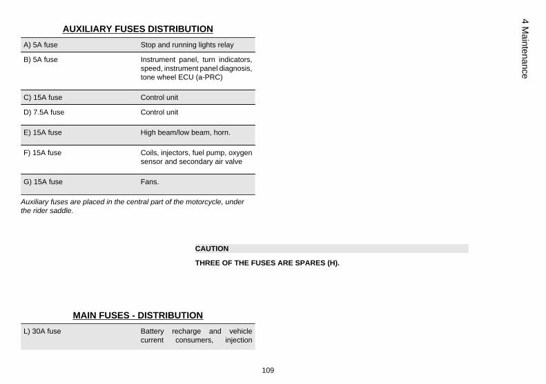
AUXILIARY FUSES DISTRIBUTIONA) 5A fuse Stop and running lights relay
B) 5A fuse Instrument panel, turn indicators,speed, instrument panel diagnosis,tone wheel ECU (a-PRC)
C) 15A fuse Control unit
D) 7.5A fuse Control unit
E) 15A fuse High beam/low beam, horn.
F) 15A fuse Coils, injectors, fuel pump, oxygensensor and secondary air valve
G) 15A fuse Fans.
Auxiliary fuses are placed in the central part of the motorcycle, underthe rider saddle.
CAUTION
THREE OF THE FUSES ARE SPARES (H).
MAIN FUSES - DISTRIBUTIONL) 30A fuse Battery recharge and vehicle
current consumers, injection
109
4 Maintenance

current consumers (red and red/white cables), fan relay.
Main fuses are placed in the rear part of the motorcycle, under thepassenger seat.
CAUTION
THERE IS ONE SPARE FUSE (I).
04_14
Lamps (04_14, 04_15, 04_16, 04_17)
It is not necessary to remove the windshield to replace the high / low beam light bulbs.
In the front headlight assembly there are:
• one LED daylight running light (1);• two high/low beam light bulbs (2).
Front turning indicators (3) are placed on the side fairing.
For replacement:
• Rest the vehicle on its stand.
110
4 M
aint
enan
ce
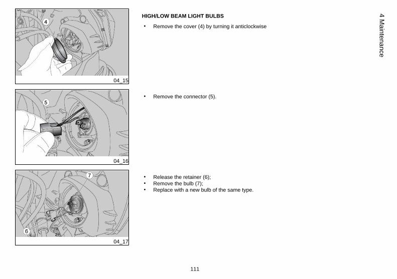
04_15
HIGH/LOW BEAM LIGHT BULBS
• Remove the cover (4) by turning it anticlockwise
04_16
• Remove the connector (5).
04_17
• Release the retainer (6);• Remove the bulb (7);• Replace with a new bulb of the same type.
111
4 Maintenance

04_18
Headlight adjustment (04_18, 04_19, 04_20)
NOTE
IN COMPLIANCE WITH LOCAL LEGISLATION, SPECIFIC PROCEDURES MUSTBE FOLLOWED WHEN ALIGNING THE LIGHTS.
04_19
To quickly and easily check the alignment of the front light, place the vehicle on a levelsurface 10 m (32.8 ft) away from a vertical wall. Turn on the dipped beam light, sit onthe vehicle and check that the light beam projected onto the wall is a little below thelevel of the headlight (about 9/10 of the total height).To carry out vertical adjustment of the light beam:
• Rest the vehicle on its stand.• Working from the rear side of the windshield, use a crosshead screwdriver
to operate on the specific central screws (1). SCREW it (clockwise) to raisethe light beams; UNDO the screw (anticlockwise) to lower the light beam.
• With these screws, it is possible to adjust the inclination of the front headlightassembly.
NOTE
CHECK THAT THE LIGHT BEAM VERTICAL DIRECTION IS CORRECT.
112
4 M
aint
enan
ce
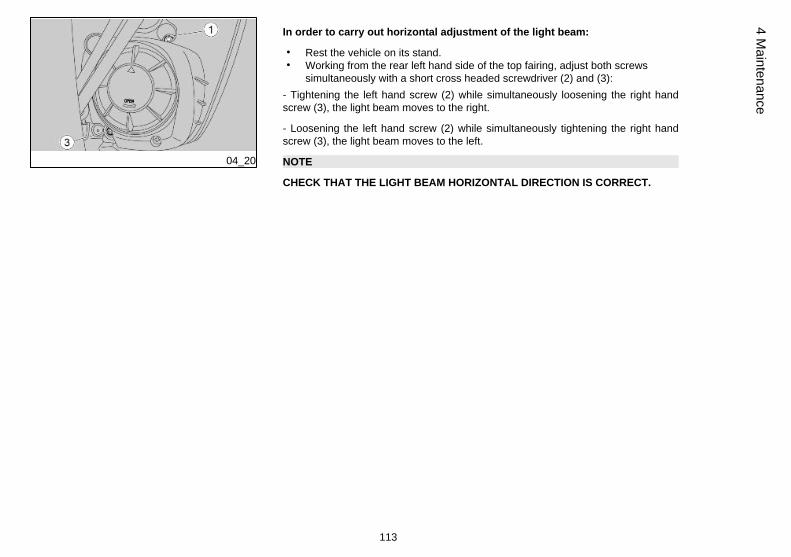
04_20
In order to carry out horizontal adjustment of the light beam:
• Rest the vehicle on its stand.• Working from the rear left hand side of the top fairing, adjust both screws
simultaneously with a short cross headed screwdriver (2) and (3):- Tightening the left hand screw (2) while simultaneously loosening the right handscrew (3), the light beam moves to the right.
- Loosening the left hand screw (2) while simultaneously tightening the right handscrew (3), the light beam moves to the left.
NOTE
CHECK THAT THE LIGHT BEAM HORIZONTAL DIRECTION IS CORRECT.
113
4 Maintenance

04_21
Front direction indicators (04_21)
• Rest the vehicle on its stand.• Loosen and remove screw (1).• Remove glass (2).• Press bulb (3) slightly and turn it anticlockwise.• Pull the bulb (3) out of its fitting.• Insert a bulb of the same type adequately.
WARNING
IF PARABOLE (4) STICKS OUT OF ITS FITTING, INSERT IT AGAIN PROPERLY.
Rear optical unit
This vehicle has a LED taillight; have it replaced at an Official Aprilia Dealer.
114
4 M
aint
enan
ce

04_22
Rear turn indicators (04_22)
• Rest the vehicle on its stand.• Loosen and remove screw (1).• Remove glass (2).• Press bulb (3) slightly and turn it anticlockwise.• Pull the bulb (3) out of its fitting.• Insert a bulb of the same type adequately.
04_23
Number plate light (04_23)
• Rest the vehicle on its stand.• Unscrew and remove the screw.• Take out the license plate light bulb holder.• Slide off and replace the bulb with another of the same type.
Brake light
CAUTION
TO REMOVE, CHECK AND REPLACE THE BULB, PLEASE CONTACT AN OfficialAprilia Dealer. IF YOU ARE ADEQUATELY TRAINED AND EXPERIENCED, RE-FER TO THE INSTRUCTIONS IN THIS WORKSHOP BOOKLET AVAILABLE ALSOAT ANY DEALER.
115
4 Maintenance

Rear-view mirrors (04_24, 04_25)
• Park the vehicle on its centre stand on safe and level ground.• Move the protection casing (1) (if applicable).
HOLD THE REAR-VIEW MIRROR (4) TO AVOID DROPPING IT BY ACCIDENT.
04_24
• Keep the screw (2) blocked and completely unscrew the nut (3).
HANDLE PLASTIC AND PAINTED COMPONENTS WITH CARE, DO NOTSCRATCH OR SPOIL THEM.
• Remove the rear-view mirror (4).
CAUTION
REPEAT THE PROCEDURE TO REMOVE THE OTHER MIRROR.
AFTER REFITTING, ADJUST THE REAR-VIEW MIRRORS CORRECTLY ANDTIGHTEN THE NUTS IN ORDER TO ENSURE STABILITY.
116
4 M
aint
enan
ce

04_25
After refitting:
• Adjust the rear-view mirror angle correctly.
04_26
Front and rear disc brake (04_26, 04_27, 04_28)
CAUTION
CHECK BRAKE PADS FOR WEAR MAINLY BEFORE EACH RIDE.
04_27
To perform a quick pad wear check:
• Rest the vehicle on its stand.• Carry out a visual inspection of brake disc and pads as follows:
- inspect the front brake callipers from above and behind (1);
- inspect the rear brake calliper (2) from below and behind;
CAUTION
EXCESSIVE WEAR OF THE FRICTION MATERIAL MAKES THE PAD METALSUPPORT GET INTO CONTACT WITH THE DISC, WHICH RESULTS IN A MET-
117
4 Maintenance

ALLIC NOISE AND SPARKS IN THE CALLIPER; THEREFORE, BRAKING EFFI-CIENCY AND DISC SAFETY AND INTEGRITY ARE AT RISK.
04_28
If the friction material thickness (even of one front (3) or rear (4) pad) is reduced to avalue of about 1.5 mm (0.06 in) (or even if one of the wear indicators is not veryvisible), contact an Official Aprilia Dealer to have the calliper pads replaced.
USE ORIGINAL PADS ONLY.
IF NON ORIGINAL PADS ARE USED THE PERFORMANCE OF THE BRAKINGSYSTEM COULD BE COMPROMISED AND/OR DAMAGED.
04_29
Periods of inactivity (04_29)
Take some measures to avoid the side effects of not using the scooter. Besides, it isnecessary to carry out general repairs and checks before garaging the motorcycle asone can forget to do so afterwards.
Proceed as follows:
• Remove the battery.• Wash and dry the vehicle.• Polish the painted surfaces.• Inflate the tyres.• Set the vehicle in a room with no heating or humidity, with minimum temper-
ature variations and not exposed to sun rays.• Wrap and tie a plastic bag around the exhaust pipe opening to keep moisture
out.
118
4 M
aint
enan
ce

NOTE
PLACE A SUITABLE SUPPORT UNDER THE VEHICLE TO KEEP BOTH WHEELSOFF THE GROUND.
• Put the vehicle on the front stand (optional) and on the back stand (optional).• Cover the vehicle (do not use plastic or waterproof materials).
After storage
NOTE
TAKE THE PLASTIC BAGS OFF THE EXHAUST PIPE OPENING.
• Uncover and clean the vehicle.• Check the battery for correct charge and install it.• Refill the fuel tank.• Carry out the pre-ride checks.
CAUTION
TEST RIDE THE VEHICLE AT MODERATE SPEED FOR A FEW KILOMETRES INAN AREA AWAY FROM TRAFFIC.
Cleaning the vehicle (04_30, 04_31, 04_32)
Clean the motorcycle frequently if exposed to adverse conditions, such as:• Air pollution (cities and industrial areas).• Salinity and humidity in the atmosphere (seashore areas, hot and wet weath-
er).
119
4 Maintenance

• Special environmental/seasonal conditions (use of salt, anti-icing chemicalproducts on the roads in winter).
• Always clean off any smog and pollution residue, tar stains, insects, birddroppings, etc. from the bodywork.
• Avoid parking the vehicle under trees. During some seasons, resins, fruits orleaves containing aggressive chemical substances that may damage thepaintwork may fall from trees.
CAUTION
BEFORE WASHING THE VEHICLE, COVER THE ENGINE AIR INTAKES AND THEEXHAUST PIPES.
CAUTION
CLEAN THE INSTRUMENT PANEL WITH A SOFT, DAMP CLOTH.
CAUTION
AFTER CLEANING YOUR MOTORCYCLE, BRAKING EFFICIENCY MAY BE TEM-PORARILY AFFECTED DUE TO THE PRESENCE OF WATER ON THE FRICTIONSURFACES OF THE BRAKING CIRCUIT. ALLOW LONGER BRAKING DISTAN-CES TO PREVENT ACCIDENTS. BRAKE REPEATEDLY TO RESTORE NORMALOPERATION. CARRY OUT THE PRE-RIDE CHECKS.
120
4 M
aint
enan
ce

04_30
04_31
04_32
To clean off dirt and mud deposited from painted surfaces, soften caked dirt with alow-pressure water jet. Sponge off using a car body sponge soaked in a car bodyshampoo and water solution (2 - 4% parts of shampoo in water). Then rinse with plentyof water, and dry with a chamois leather. To clean the engine outer parts, use de-greasing detergent, brushes and old cloths. Anodised or painted aluminium parts suchas forks, wheel rims, frame, footrests etc. should be washed using water and mildsoap. Using aggressive detergents may damage the surface treatment of these com-ponents.
TO CLEAN THE HEADLIGHTS USE A SPONGE SOAKED IN WATER AND MILDDETERGENT, RUBBING THE SURFACE GENTLY AND RINSING FREQUENTLYWITH PLENTY OF WATER. REMEMBER TO CLEAN THE VEHICLE CAREFULLYBEFORE APPLYING SILICON WAX POLISH. DO NOT POLISH MATT-PAINTEDSURFACES WITH POLISHING PASTE. THE VEHICLE SHOULD NEVER BEWASHED IN DIRECT SUNLIGHT, ESPECIALLY DURING SUMMER, OR WITH THEBODYWORK STILL HOT AS THE CAR SHAMPOO CAN DAMAGE THE PAINT-WORK IF IT DRIES BEFORE BEING RINSED OFF.
CAUTION
DO NOT USE WATER (OR LIQUIDS) AT TEMPERATURES OVER 40°C (104°F)WHEN CLEANING THE VEHICLE PLASTIC PARTS. DO NOT AIM HIGH PRES-SURE AIR/WATER JETS OR STEAM JETS DIRECTLY TO THE FOLLOWINGPARTS: WHEEL HUBS, CONTROLS ON THE RIGHT AND LEFT SIDE OF THEHANDLEBAR, BEARINGS, BRAKE PUMPS, INSTRUMENTS AND GAUGES, EX-HAUST SILENCER, IGNITION SWITCH/STEERING LOCK. DO NOT USE ALCO-HOL OR SOLVENTS TO CLEAN ANY RUBBER OR PLASTIC SADDLE COMPO-NENTS: USE WATER AND MILD SOAP.
CAUTION
DO NOT USE SOLVENTS OR PETROL BY-PRODUCTS (ACETONE, TRICHLORO-ETHYLENE, TURPENTINE, PETROL, THINNERS) TO CLEAN THE SADDLE. USE
121
4 Maintenance
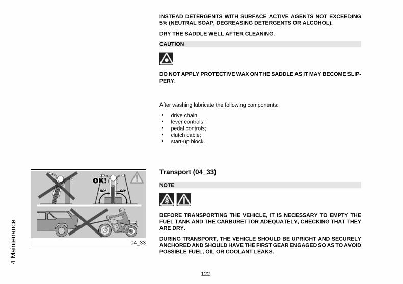
INSTEAD DETERGENTS WITH SURFACE ACTIVE AGENTS NOT EXCEEDING5% (NEUTRAL SOAP, DEGREASING DETERGENTS OR ALCOHOL).
DRY THE SADDLE WELL AFTER CLEANING.
CAUTION
DO NOT APPLY PROTECTIVE WAX ON THE SADDLE AS IT MAY BECOME SLIP-PERY.
After washing lubricate the following components:
• drive chain;• lever controls;• pedal controls;• clutch cable;• start-up block.
04_33
Transport (04_33)
NOTE
BEFORE TRANSPORTING THE VEHICLE, IT IS NECESSARY TO EMPTY THEFUEL TANK AND THE CARBURETTOR ADEQUATELY, CHECKING THAT THEYARE DRY.
DURING TRANSPORT, THE VEHICLE SHOULD BE UPRIGHT AND SECURELYANCHORED AND SHOULD HAVE THE FIRST GEAR ENGAGED SO AS TO AVOIDPOSSIBLE FUEL, OIL OR COOLANT LEAKS.
122
4 M
aint
enan
ce

IN CASE OF FAILURE, DO NOT TOW THE VEHICLE BUT CONTACT A ROADASSISTANCE SERVICE INSTEAD TO HAVE THE INFLAMMABLE FLUIDSDRAINED .
04_34
Chain backlash check (04_34)
To check the clearance:
• Shut off the engine.• Rest the vehicle on its stand.• Engage neutral gear.• Check that vertical oscillation at a point between the pinion and the sprocket
on the lower branch of the chain is around 30 mm (1.18 in).• Move the vehicle forward so as to check the chain vertical oscillation in other
positions too. clearance should remain constant at all wheel rotation phases.Adjust clearance if it is uniform but higher or lower than 30 mm (1.18 in).
CAUTION
IF CLEARANCE IS GREATER IN SOME POSITIONS, THIS MEANS THAT SOMEELEMENTS OF THE CHAIN ARE CRUSHED OR SEIZED. IN THIS CASE, THETRANSMISSION CHAIN MUST BE REPLACED.
TO AVOID RISK OF SEIZURE, LUBRICATE THE CHAIN ON A REGULAR BASIS.
123
4 Maintenance
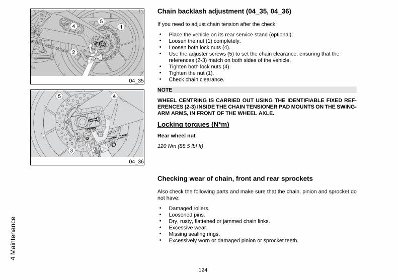
04_35
04_36
Chain backlash adjustment (04_35, 04_36)
If you need to adjust chain tension after the check:
• Place the vehicle on its rear service stand (optional).• Loosen the nut (1) completely.• Loosen both lock nuts (4).• Use the adjuster screws (5) to set the chain clearance, ensuring that the
references (2-3) match on both sides of the vehicle.• Tighten both lock nuts (4).• Tighten the nut (1).• Check chain clearance.
NOTE
WHEEL CENTRING IS CARRIED OUT USING THE IDENTIFIABLE FIXED REF-ERENCES (2-3) INSIDE THE CHAIN TENSIONER PAD MOUNTS ON THE SWING-ARM ARMS, IN FRONT OF THE WHEEL AXLE.
Locking torques (N*m)Rear wheel nut
120 Nm (88.5 lbf ft)
Checking wear of chain, front and rear sprockets
Also check the following parts and make sure that the chain, pinion and sprocket donot have:
• Damaged rollers.• Loosened pins.• Dry, rusty, flattened or jammed chain links.• Excessive wear.• Missing sealing rings.• Excessively worn or damaged pinion or sprocket teeth.
124
4 M
aint
enan
ce
CAUTION
IF THE CHAIN ROLLERS ARE DAMAGED, THE PINS ARE LOOSENED AND/ORTHE SEAL RINGS ARE MISSING OR DAMAGED, THE WHOLE CHAIN APPARA-TUS (PINION, SPROCKET AND CHAIN) SHOULD BE REPLACED.
CAUTION
LUBRICATE THE CHAIN ON A REGULAR BASIS, PARTICULARLY IF YOU FINDDRY OR RUSTY PARTS. FLATTENED OR JAMMED CHAIN LINKS SHOULD BELUBRICATED AND GOOD OPERATING CONDITIONS RESTORED. IF REPAIR ISNOT POSSIBLE, CONTACT AN Official Aprilia Dealer TO HAVE IT REPLACED.
Chain lubrication and cleaning
Never wash the chain with high pressure air/water jets or steam jets or highly flam-mable solvents.
• Wash the chain with fuel oil or kerosene. Maintenance operations should bemore frequent if there are signs of quick rust.
Lubricate the chain whenever necessary.
• After washing and drying the chain, lubricate it with spray grease for sealedchains.
THE TRANSMISSION CHAIN HAS RUBBER O-RINGS BETWEEN THE SIDEPLATES OF THE CHAIN ITSELF THAT ARE USED TO HOLD THE GREASE. UT-MOST ATTENTION IS REQUIRED WHEN ADJUSTING, LUBRICATING, WASHINGOR REPLACING THE CHAIN.CHAIN LUBRICANTS AVAILABLE ON THE MARKET CAN CONTAIN SUBSTAN-CES THAT DAMAGE THE CHAIN'S RUBBER O-RINGS.
125
4 Maintenance

NEVER USE THE VEHICLE JUST AFTER LUBRICATING THE CHAIN, AS THELUBRICANT WOULD BE SPRAYED OUTWARD AND SPREAD OUT IN THE SUR-ROUNDING AREA.
126
4 M
aint
enan
ce

Tuono V4
Chap. 05Technical data
127

DIMENSIONS
Max. length 2,065 mm (81.30 in)
Max. width 820 mm (32.28 in)
Max. height (at handlebar) 1,090 mm (42.91 in)
Saddle height 826 mm (32.52 in)
Wheelbase 1,445 mm (56.89 in)
Minimum ground clearance 125 mm (4.92 in)
Kerb weight 193 kg (425 lb)
Kerb weight 204 kg (449 lb)
Full loaded weight (rider only) 279 kg (615 lb)
ENGINEModel V4
Type 65° longitudinal V-4, 4-stroke, 4valves per cylinder, doubleoverhead camshafts.
Engine capacity 999 cm³ (60.96 cu.in)
Bore / stroke 78 mm / 52.26 mm (3.07 in / 2.06in)
128
5 Te
chni
cal d
ata
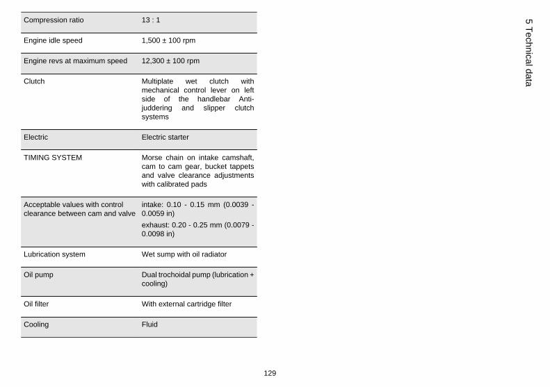
Compression ratio 13 : 1
Engine idle speed 1,500 ± 100 rpm
Engine revs at maximum speed 12,300 ± 100 rpm
Clutch Multiplate wet clutch withmechanical control lever on leftside of the handlebar Anti-juddering and slipper clutchsystems
Electric Electric starter
TIMING SYSTEM Morse chain on intake camshaft,cam to cam gear, bucket tappetsand valve clearance adjustmentswith calibrated pads
Acceptable values with controlclearance between cam and valve
intake: 0.10 - 0.15 mm (0.0039 -0.0059 in)exhaust: 0.20 - 0.25 mm (0.0079 -0.0098 in)
Lubrication system Wet sump with oil radiator
Oil pump Dual trochoidal pump (lubrication +cooling)
Oil filter With external cartridge filter
Cooling Fluid
129
5 Technical data

Cooling system 3-way thermostatic valve, coolingradiator with electric fan andexpansion tank
Coolant pump Centrifugal bearingless aspiratingpump with integrated ceramicgasket
Air filter Paper
Alternatively:
Air filter In cotton
CAPACITY
Fuel capacity (reserve included) 17 l (3.74 UK gal)
Fuel tank reserve 3.6 l (0.79 UK gal)
Engine oil oil and filter change 4 l (0.88 UKgal)
Coolant 2.6 l (0.57 UK gal)
Seats 2
Maximum weight capacity 197 kg (434 lb)
130
5 Te
chni
cal d
ata

GEAR RATIOS
Primary drive ratio 44 / 73 (with gears)
1st gear ratio 15 /39 (secondary)
2nd gear ratio 16 /33 (secondary)
3rd gear ratio 20 / 34 (secondary)
4th gear ratio 22 /32 (secondary)
5th gear ratio 26 /34 (secondary)
6th gear ratio 27 /33 (secondary)
Final drive gear ratio 16 / 42
DRIVE CHAIN
Type 525
With sealed master link
Model Regina 110 links
131
5 Technical data

TRACTION CONTROL
a-PRC system (on vehicles with a-PRC)
(Aprilia Performance RideControl), which includes tractioncontrol, wheelie control, launchcontrol and clutchless gear shiftfunctions.
FUEL SYSTEM
Fuel Premium unleaded petrol,minimum octane rating 95 (NORM)and 85 (NOMM)
FUEL SYSTEM
Throttle body diameter 48 mm (1.89 in)
Type Electronic injection (multipoint), 2throttle bodies motorised (ride bywire), 2 dynamic air intakes.Selectable multimap.
132
5 Te
chni
cal d
ata
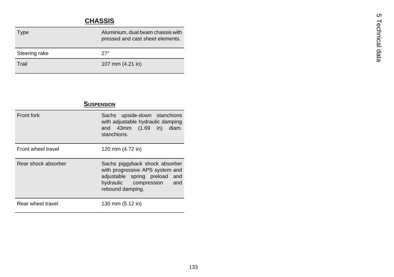
CHASSISType Aluminium, dual beam chassis with
pressed and cast sheet elements.
Steering rake 27°
Trail 107 mm (4.21 in)
SUSPENSION
Front fork Sachs upside-down stanchionswith adjustable hydraulic dampingand 43mm (1.69 in) diam.stanchions.
Front wheel travel 120 mm (4.72 in)
Rear shock absorber Sachs piggyback shock absorberwith progressive APS system andadjustable spring preload andhydraulic compression andrebound damping.
Rear wheel travel 130 mm (5.12 in)
133
5 Technical data

BRAKES
Front Double floating disc, Ø 320 mm(12.60 in), radially-mountedcalliper with four Ø 32 mm (1.26 in)pistons and two calliper padsBrake pipe in metal braid.
Rear disc type -220 mm diam. (8.66inches), 2-piston callipers - 32 mmdiam. (1.25 inches) - pump withbuilt-in tank and metal braid pipe.
WHEEL RIMS
Front wheel rim 3.50 x 17"
Rear wheel rim 6.00 x 17"
TYRES
Tyre model Pirelli DIABLO Rosso Corsa
Michelin Power Pure
Metzeler RACETEC K3
Pirelli Diablo Super Corsa SP
Front tyre 120/70 ZR17 (58W)
134
5 Te
chni
cal d
ata
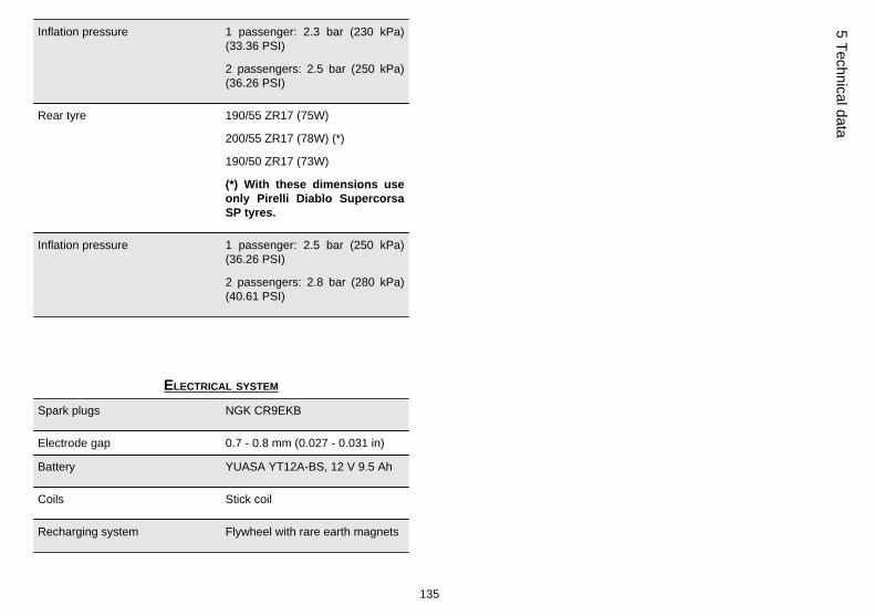
Inflation pressure 1 passenger: 2.3 bar (230 kPa)(33.36 PSI)
2 passengers: 2.5 bar (250 kPa)(36.26 PSI)
Rear tyre 190/55 ZR17 (75W)
200/55 ZR17 (78W) (*)
190/50 ZR17 (73W)
(*) With these dimensions useonly Pirelli Diablo SupercorsaSP tyres.
Inflation pressure 1 passenger: 2.5 bar (250 kPa)(36.26 PSI)
2 passengers: 2.8 bar (280 kPa)(40.61 PSI)
ELECTRICAL SYSTEM
Spark plugs NGK CR9EKB
Electrode gap 0.7 - 0.8 mm (0.027 - 0.031 in)
Battery YUASA YT12A-BS, 12 V 9.5 Ah
Coils Stick coil
Recharging system Flywheel with rare earth magnets
135
5 Technical data
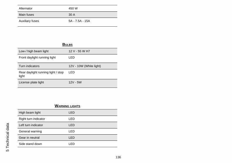
Alternator 450 W
Main fuses 30 A
Auxiliary fuses 5A - 7.5A - 15A
BULBS
Low-/ high beam light 12 V - 55 W H7
Front daylight running light LED
Turn indicators 12V - 10W (White light)
Rear daylight running light / stoplight
LED
License plate light 12V - 5W
WARNING LIGHTS
High beam light LED
Right turn indicator LED
Left turn indicator LED
General warning LED
Gear in neutral LED
Side stand down LED
136
5 Te
chni
cal d
ata

Fuel reserve LED
ABS NOT ENABLED
05_01
Kit equipment (05_01, 05_02)
• An Allen key is located under the passenger seat, used to remove the saddlefastener screws in order to remove the saddle and allow access to the toolkitcompartment.
• To remove the passenger seat, see the section Vehicle / Saddle opening.
137
5 Technical data

05_02
The tools supplied are:
1. A toolkit pouch2. Cross headed screwdriver with non reversible handle3. 17 mm (0.67 in) open ended spanner4. 8 - 10 mm (0.31 - 0.39 in) open ended spanner5. Bent 3 mm (0.12 in) Allen key6. Bent 5 mm (0.67 in) Allen key7. Wrench for preload adjustment ring nut8. Wrench extension9. Fuse removal pincers
138
5 Te
chni
cal d
ata

Tuono V4
Chap. 06Programmedmaintenance
139

Scheduled maintenance table
Adequate maintenance is fundamental to ensure long-lasting, optimum operation andperformance of your vehicle.
To this end, Aprilia offers a set of checks and maintenance services (at the owner'sexpense), that are summarised in the table shown on the following page. Any minorfaults must be reported without delay to an Authorised Aprilia Dealer or Sub-Deal-er without waiting until the next scheduled service to solve it.
All scheduled services must be carried out at the specified intervals and mileage, assoon as the predetermined mileage is reached. Carrying out scheduled services ontime is essential for the validity of your warranty. For further information regardingWarranty procedures and ''Scheduled Maintenance'', please refer to the ''WarrantyBooklet''.
NOTE
CARRY OUT MAINTENANCE OPERATIONS AT HALF THE INTERVALS SPECI-FIED IF THE VEHICLE IS USED IN PARTICULAR RAINY OR DUSTY CONDI-TIONS, OFF ROAD OR FOR TRACK USE.
I: INSPECT AND CLEAN, ADJUST, LUBRICATE OR REPLACE IF NECESSARY
C: CLEAN, R: REPLACE, A: ADJUST, L: LUBRICATE
(1) Check at each engine start
(2) Check and clean and adjust or replace, if necessary, before every journey.
(3) Check and clean and adjust or replace, if necessary, every 1000 Km (621 mi)
(4) Replace every 2 years
(5) Replace every 4 years
(6) Every 5000 Km (3107 mi) if the vehicle is used for racing
(7) Every 10000 Km (6213 mi) if the vehicle is used for racing
140
6 Pr
ogra
mm
ed m
aint
enan
ce

ROUTINE MAINTENANCE TABLE
Km x 1000 1 10 20 30 40
Rear shock absorber (6) I I
Set up (6) I I I I I
Cylinder equalisation I I I I
Spark plug (6) I R I R
Drive chain (3) I - L I - L I - L I - L I - L
Clutch cable L L L L L
Control cables and controls (6) I I I I I
Sprocket - pinion (6) I I I I
Rear suspension bearings - linkages I I
Steering bearings and steering clearance (6) I I I I
Wheel bearings (6) I I I I
Control unit diagnosis I I I I
Brake discs (6) I I I I I
Air filter (6) I R I R
Engine oil filter (6) R R R R R
Engine oil filter (on rose pipe) C
Fork I I
General vehicle operation (6) I I I I I
Valve clearance (7) A A
Cooling system (6) I I I I
141
6 Programm
ed maintenance

Km x 1000 1 10 20 30 40
Brake systems (6) I I I I I
Light circuit I I I I I
Stand switch I I I I
Safety switches I I I I I
Stop switches I I I I
Brake fluid (4) I I I I I
Coolant (4) I I I I I
Fork oil (7) R R
Engine oil (6) R R R R R
Light aiming I I I I
Fork oil seals (6) I I I I
Anti-vibration buffers I I
Tyres - pressure/wear (2) I I I I I
Wheels (6) I I I I I
Tightening torques (6) I I I I I
Tightening of clutch cover, flywheel and oil sump screws I I I I I
Fault warning light on instrument panel (1)
Fuel lines (5) I I I I
Clutch wear (7) I I
Brake pad wear (2) I I I I I
142
6 Pr
ogra
mm
ed m
aint
enan
ce

RECOMMENDED PRODUCTS TABLE
Product Description Specifications
ENI i-RIDE APRILIA RACING 5W-40 Engine oil Use branded oils with performance equivalentto or exceeding ACEA A3 - API SL - JASO MA- JASO MA2
AGIP MP GREASE Black smooth textured lithium-calcium soapbased grease containing EP (extremepressure) additives with optimal water-repellent properties
ISO L-X-BCHB 2 - DIN 51 825 KP2K-20
AGIP PERMANENT SPECIAL Ethylene glycol-based antifreeze fluid withorganic inhibition additives. Red, ready for use
ASTM D 3306 - ASTM D 4656 - ASTM D 4985- CUNA NC 956-16
AGIP BRAKE 4 Brake fluid SAE J 1703 -FMVSS 116 - DOT 3/4 - ISO 4925- CUNA NC 956 DOT 4 synthetic fluid
AGIP ARNICA SA 32 Fork oil ISO-L-HV
143
6 Programm
ed maintenance

144
6 Pr
ogra
mm
ed m
aint
enan
ce
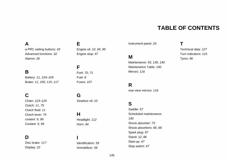
TABLE OF CONTENTS
Aa-PRC setting buttons: 43Advanced functions: 32Alarms: 26
BBattery: 11, 103–105Brake: 11, 100, 115, 117
CChain: 123–125Clutch: 11, 75Clutch fluid: 11Clutch lever: 75coolant: 9, 99Coolant: 9, 99
DDisc brake: 117Display: 22
EEngine oil: 10, 94, 95Engine stop: 47
FFork: 70, 71Fuel: 8Fuses: 107
GGearbox oil: 10
HHeadlight: 112Horn: 44
IIdentification: 59Immobilizer: 56
Instrument panel: 20
MMaintenance: 93, 139, 140Maintenance Table: 140Mirrors: 116
Rrear-view mirrors: 116
SSaddle: 57Scheduled maintenance:140Shock absorber: 73Shock absorbers: 66, 68Spark plug: 97Stand: 12, 86Start-up: 47Stop switch: 47
TTechnical data: 127Turn indicators: 115Tyres: 96
145

THE VALUE OF SERVICE
As a result of continuous updates and specific technical training programmes for Aprilia products, only Aprilia Official Network mechanics know this vehicle fully and have the specific tools necessaryto carry out maintenance and repair operations correctly.
The reliability of the vehicle also depends on its mechanical conditions. Checking the vehicle before riding it, its regular maintenance and the use of original Aprilia spare parts only are essential factors!
For information on the nearest Official Dealer and/or Service Centre consult our website:
www.aprilia.com
Only by requesting aprilia original spare parts can you be sure of purchasing products that were developed and tested during the actual vehicle design stage. All aprilia original spare parts undergoquality control procedures to guarantee reliability and durability.
The descriptions and images in this publication are given for illustrative purposes only and are not binding.
While the basic characteristics as described and illustrated in this booklet remain unchanged, Piaggio & C. S.p.A. reserves the right, at any time and without being required to update this publicationbeforehand, to make any changes to components, parts or accessories, which it considers necessary to improve the product or which are required for manufacturing or construction reasons.
Not all versions/models shown in this publication are available in all countries. The availability of individual versions/models should be confirmed with the official aprilia sales network.
The Aprilia trademark is the property of Piaggio & C. S.p.A.
© Copyright 2012 - Piaggio & C. S.p.A. All rights reserved. Reproduction of this publication in whole or in part is prohibited.
Piaggio & C. S.p.A. Viale Rinaldo Piaggio, 25 - 56025 PONTEDERA (PI), Italy
www.piaggio.com